1
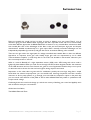
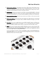
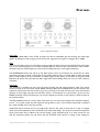
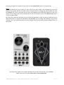
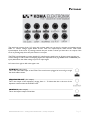
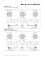
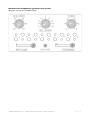
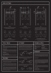
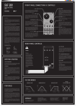
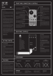
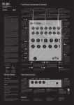
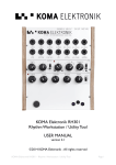
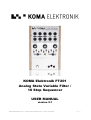
KOMA Elektronik FT201
Analog State Variable Filter /
10 Step Sequencer
USER MANUAL
version 2.1
KOMA Elektronik FT201 – Analog State Variable Filter / 10 Step Sequencer
Page 1
TABLE OF CONTENTS:
3. Introduction
4. Getting Started
5. Features
7. Control Voltage Theory
9. Patch Bay
11. Basic Settings and Examples
13. Technical Specifications
15. Warranty
15. Imprint
WARNING:
Only use the KOMA Elektronik power supply shipped with
the FT201. Power sources rated with voltages greater
than 9V DC and/or wrong polarity may cause damage or
malfunction to the FT201s circuitry and will void the
warranty!
KOMA Elektronik FT201 – Analog State Variable Filter / 10 Step Sequencer
Page 2
INTRODUCTION
Filters are possibly the sound tool per se when it comes to defining your own sound. There's a lot of
discussion going on about different filter topologies and their respective sound and how to electronically
solve these different approaches. At KOMA Elektronik we went for a very versatile filter architecture called
state variable flter. One of the advantages of this filter is that you have band pass, high pass and lowpass
characteristics available simultaneously for a given input. Other musically convenient advantages are the
independently adjustable Q (resonance) and gain that can be set without affecting other variables.
There are two gain cells in the signal path of a voltage-controlled state variable filter so there are different
approaches to represent those gain cells. Usually these gain cells are represented by an IC called
'transconductance amplifier' (a small chip) but for the FT201 we decided to take another electronic part
here commonly known as 'vactrols'.
What is a vactrol? Basically it's a light dependent resistor (LDR) and a LED kissing each other under a
lightproof plastic blanket. When you send current through the LED, it shines brighter, therefor the resistance
of the LDR decreases and vice versa. Vactrols are great for sound applications because they are not prone
to distortion and are known for their soft and organic, analog response and sound.
Sequencers on the other side are great tools for modulation, possibly the most logic thing after a simple
knob. With the onboard step-sequencer you can twiddle with charming frequencies and their resonant
overtones or find a pretty pattern to go through your tone. With the sequencer output on the patch bay
you can control other features of the pedal as well as other KOMA Elektronik pedals or synthesizers that
accept control voltage.
Combining these two sound tools brings up a whole new variety of defining your sound and playfully work
with it. Have fun with your new machine!
All the best from Berlin,
The KOMA Elektronik Team
KOMA Elektronik FT201 – Analog State Variable Filter / 10 Step Sequencer
Page 3
GETTING STARTED
1)
Unpack your machine: The package comes with the FT201 pedal, a 9VDC, 500mA, centernegative power supply and this manual. Save the box and packaging material in case you ever need
to ship your pedal! Make sure that the power supply is rated for the line voltage of your country:
120 VAC for the USA, 220 VAC for Europe or most other countries.
2)
Connections: Connect your instrument to the FT201 by using the AUDIO INPUT on the patch
bay. Connect the LO PASS of the FT201 to your amp. To connect the Motion Controller (the builtin expression function) plug in a ¼ inch jack cable from SENSOR to CUTOFF CV on the patch bay.
3)
Set up the FT201/ Amp: Set all the rotary controls on the FT201 to 0. Turn down the volume
of your amplifier.
4)
Power up / Bypass: Connect the FT201 power supply to the FT201 DC input on the backside
of the pedal. When you press the bypass switch the EFFECT ON/OFF led will light up, this means
the effect is ON.
5)
Set levels: Turn on your amplifier. Make sure the EFFECT ON/OFF indicator is OFF. Play your
instrument and adjust the volume of the amplifier so it is at a comfortable level. Press the Bypass
switch and the EFFECT ON/OFF indicator will turn on green which means the effect is active.
6)
Play: Now go nuts. If necessary, adjust the INPUT GAIN slider control to match the levels of the
processed signal and the bypassed signal. Be aware of volume changes in your signal when using the
FT201. This is especially true when the RESONANCE slider control is set to HIGH, don't turn it up
too much, you'll get crazy and very high pitched sounds!
You can use the Motion Controller to adjust the EXTERNAL CLOCK, CUTOFF, RESONANCE and
SEQUENCER RESET. Be sure to read through the Control Voltage Theory section to understand all
CV features and the way to use them properly.
KOMA Elektronik FT201 – Analog State Variable Filter / 10 Step Sequencer
Page 4
FEATURES
Fig.1 Frontpanel Features
Input Gain
The INPUT GAIN slider of the FT201 provides you with an adjustable gain for boosting low level input
signals. By sliding from left to right you can boost your signal from zero gain to 100 gain (0 to +20dB).
Filter
The use of the filter section of the FT201 is pretty straight forward. There is the CUTOFF knob with which
you set the cutoff frequency for the filter, simultaneously for all three filter characteristics. Fully counterclockwise sets the cutoff frequency to the lowest and fully clockwise to the highest frequency.
The RESONANCE slider sets the Q of the filter, better known as resonance. The resonance of a filter
determines the gain increase of the signal at the cutoff frequency. Set it to LOW (left) to leave the signal
gain at cutoff frequency at zero and slide it to HIGH (right) to hear plenty of resonance at the given cutoff
frequency. Be aware of the fact that the filter might start self-oscillating when you are at or near maximum
resonance.
Sequencer
The sequencer is divided into two parts: A control section and the actual sequencer itself. The control
section consists of the two knobs named SPEED and SEQ. LENGTH. The SPEED knob sets the speed of the
sequencer which means the time it takes to go from one step to the next one and at the same time also the
duration of each single step (On the scale that means: 2 is the fastest, 10 is the slowest,). If you turn the
SPEED knob fully counter-clockwise you can turn the sequencer off with a 'click' (there's a built-in switch in
the potentiometer).
The SEQ. LENGTH knob is a rotary switch with which you can choose the length of the sequencer pattern
from 2 – 10, i.e. after which step the sequencer will go back to step 1. The currently active step is indicated
by a small red LED next to the step number.
Underneath these controls you find 10 small knobs that set the value of each step. It is easy to imagine
these ten knob as duplicates of the CUTOFF knob mentioned earlier. The amount set with the sequencer
knob of the active step is added to the current setting of the CUTOFF knob, or in other words: You can
shift the sequencer pattern up and down with the CUTOFF knob, similar to setting a bias voltage for
KOMA Elektronik FT201 – Analog State Variable Filter / 10 Step Sequencer
Page 5
incoming CV signals. The sequence is also present at the SEQUENCER output on the patch bay.
Sensor
One of the features on your FT201 you won't find in any other pedal is the possibility to control the
features of the pedals with the on board motion controller. Since its working with infrared LEDs we call it
the SENSOR. The motion controller can be used in many different ways. Technically speaking, it emits a CV
signal (control voltage) which can be patched up with any CV receptive socket on the KOMA pedals and f.i.
on your modular system.
By moving your hand over the sensor you can control the parameters of the CV input you patched it up to.
With the trimmer on the back of the pedal (it says SENSOR) you can change the sensitivity of the motion
controller. For more information about control voltage, check out the section Control Voltage Theory of
this manual.
Got a Eurorack system? The modular equivalent of the FT201, the SVF-201 is now available!
Want more sensors? Try the KOMA Elektronik KOMMANDER!
KOMA Elektronik FT201 – Analog State Variable Filter / 10 Step Sequencer
Page 6
CONTROL VOLTAGE THEORY
The concept of control voltage (CV) is not hard to understand: Instead of turning a knob on your pedal you
simply connect a voltage – the control voltage – to the corresponding CV input that does the job for you.
So for example if you want to make fast changes to the cutoff frequency you don't have to turn that knob all
the time back and forth until your hand falls off, but simply connect an alternating CV to the CUTOFF
input.
You can take control signals from any source for controlling the inputs of the FT201. Since the FT201 is
running on a +9V power supply you might wonder how you can use CV signals that are larger than 9V. The
answer is simple: We provide you with a trimmer for each CV input on the backside of the panel.
So whenever you notice a significant distortion or clipping in your control signal waveform or strange CV
behavior simply turn the trimpot counter-clockwise (towards the word 'CV') until you hear your desired
result. By turning it counter-clockwise you attenuate the incoming CV signal. Fully counter-clockwise means
that the incoming CV signal is completely gone, whereas fully clockwise means that the incoming CV signal
is arriving to the circuit unattenuated.
Please don't worry about the extra hole without a trimpot behind it, it is used for setting the unit at the
factory. In addition to attenuating the incoming CV you can set an offset voltage to your control voltage to
adjust the CV signal to your needs. The offset voltage is set by the corresponding knob on the front panel.
There's also a distinction between bipolar and unipolar signal. This is best explained with a few pictures.
Original CV Signal
CV Signal inside the pedal
So, what happens? The incoming CV signal is shifted around the voltage that you select with the
corresponding knob. Example: if you insert a -5V to +5V sine wave into the RESONANCE CV jack you will
KOMA Elektronik FT201 – Analog State Variable Filter / 10 Step Sequencer
Page 7
get the following results while turning the RESONANCE slider:
Original CV Signal
CV Signal inside the pedal
Low Bias Voltage
High Bias Voltage
A similar thing happens to unipolar CV signals: Their point of origin (0V) is shifted by the amount set with
the corresponding knob. In other words: You add the voltage of your knob to the voltage of your incoming
unipolar CV signal.
Original CV Signal
CV Signal inside the pedal
Now you understand control voltage, let's see what the patch bay of the FT201 can offer.
KOMA Elektronik FT201 – Analog State Variable Filter / 10 Step Sequencer
Page 8
PATCHBAY
The patch bay consists of ten 1/4” mono jack sockets which you can use for receiving and sending various
audio or control voltage signals. Blank arrows mark CV inputs/outputs, black arrows mark audio
inputs/outputs. If the arrow is pointing towards the jack socket it shows you that this is an output, if the
arrow is pointing away from the jack socket it is an input.
The FT201 was designed to accept unipolar CV only. Since the pedal runs on 9V every time you plug in a
control voltage to one of the CV accepting inputs, the respective knob (e.g. SPEED knob or SPEED IN (CV
input) determines the offset voltage of your CV input signal.
Let's start from right to left in the upper row.
AUDIO IN (audio input)
This is the main audio input of the FT201. The sound source plugged in here will go trough
the whole effect section.
SEQUENCER OUT (CV output)
This is the output of the sequencer, ranging from 0 – 7V. Note that this is the sum of the
sequencer itself and the the CUTOFF knob.
LOWPASS (audio output)
This is the lowpass output of the filter.
KOMA Elektronik FT201 – Analog State Variable Filter / 10 Step Sequencer
Page 9
BANDPASS (audio output)
This is the bandpass output of the filter.
HIGHPASS (audio output)
This is the highpass output of the filter.
Left to right, lower patchbay row:
EXT. CLOCK (CV input)
The EXT. CLOCK input is able to accept clock signals for the sequencer by overriding the
internal clock set by the SPEED knob. It reacts to rising edge triggers, proceeding one step
whenever a trigger or gate signal arrives. (see Control Voltage Theory section).
CUTOFF (CV input)
The CUTOFF CV input controls the cutoff frequency of the filter. When you insert a control
voltage into this input the CUTOFF knob determines the offset voltage (see Control Voltage
Theory section).
RESONANCE (CV input)
The RESONANCE CV input controls the amount of resonance in your given filter setting.
When you insert a control voltage into this input the RESONANCE slider determines the
offset voltage (see Control Voltage Theory section).
SEQ. RESET (CV input)
A rising edge trigger or gate signal arriving at this CV input resets the sequencer to step 1
(see Control Voltage Theory section). A trigger will reset, a gate will hold the sequencer at
step 1 as long as it is high.
SENSOR (CV output)
This is the CV output of the infrared motion sensor. The closer you move something towards
the sensor, the higher the CV raises. You can set the sensitivity of the sensor with a small
trimmer on the background called 'Sensor'. The sensor output is 0 – 8V.
KOMA Elektronik FT201 – Analog State Variable Filter / 10 Step Sequencer
Page 10
BASIC SETTINGS AND EXAMPLES
Deep Bass Punch
(plug your amp into the LO PASS output)
High tones resonance
(plug your amp into the HI PASS output)
KOMA Elektronik FT201 – Analog State Variable Filter / 10 Step Sequencer
Page 11
Distorted Low Frequencies (great for bass synths)
(plug your amp into the LO PASS output)
KOMA Elektronik FT201 – Analog State Variable Filter / 10 Step Sequencer
Page 12
TECHNICAL SPECIFICATIONS
GENERAL
Casing:
Powder coated aluminum casing, silk screened text and wooden side panels.
Dimensions:
23 cm x 15 cm x 5 cm (L x W x H) / 9″ x 6″ x 2″ (L x W x H).
Net. Weight:
850 gr / 1.8 lb.
Shipping Weight:
1 kg. / 3.0 lb including power adapter and instruction manual.
Power requirements:
9V DC power adapter, 500mA min, center polarity negative (only use the KOMA
adapter shipped with the pedal).
FEATURES
INPUT GAIN
Slide control which allows the user to set the input gain of the plugged in
instrument or line audio signal.
RESONANCE
Slide control to set the resonance of the filter. Please note that due to tolerances
in the vactrols every filter sounds a bit different and amounts of resonance can
vary with each pedal.
SPEED
Rotary control to adjust the clock speed of the built-in sequencer. If turned fully
counter clockwise, the sequencer is off and not routed to the cutoff of the filter
anymore.
SEQ. LENGTH
Rotary switch for defining the length of the sequencer pattern from 2 - 10 steps.
CUTOFF
Rotary control to to adjust the cutoff frequency of the filter.
SEQUENCER
CONTROLS (1-10)
Rotary controls to set the control voltage of each step of the sequencer pattern.
The sequencer is running through the selected amount of steps from left to right
and adds the control voltage to the the value set by the CUTOFF knob, thus
modulating the cutoff frequency in every step.
EFFFECT ON LED
Indicates if the effect is switched on or bypassed.
FOOTSWITCH
Heavy duty Alpha foot switch. Turning the effect on or off.
2 IR EMITTERS, 1 IR
RECIEVER
Calculates the distance between an object and the pedal and generates a CV signal
according to the measured distance. The CV output of this sensor appears as a CV
output on the patch bay from where you can route it to the CV input of your
desired, to-be-modulated feature.
PATCH BAY INS AND OUTS
AUDIO IN
Plug your sound source here.
HI PASS, BAND
PASS, LO PASS
Outputs of the three respective filter characteristics. All three filter outputs are
available at the same time.
SEQUENCER
CV output of the control voltage generated by the sequencer and CUTOFF knob.
EXT. CLOCK
CV input for the clock generator of the sequencer. Applying a clock signal here lets
you control/sync the speed of the sequencer by external clock sources. Try it with
the built-in motion sensor!
SEQ. RESET
CV input of the sequencer. Every time a gate signal (rising edge trigger) is fed into
this CV input, the sequencer is reset and starts again at step 1. Nicely playable with
KOMA Elektronik FT201 – Analog State Variable Filter / 10 Step Sequencer
Page 13
the built-in motion sensor.
CUTOFF
CV input that lets you control the cutoff frequency of the filter with an external
CV source or the built-in motion sensor.
RESONANCE
CV input that lets you control the resonance of the filter by means of an external
CV source of the built-in motion sensor.
SENSOR
CV output of the onboard motion sensor for usage with CV inputs on the pedal,
other KOMA Elektronik pedals or other voltage-controlled devices.
All patch bay inputs and outputs are mono 1/4″ phone jacks.
BACKPANEL
DC POWER
INPUT
Accepts standard 9 volt power adapters, center pin negative, 500mA min. (KOMA
Elektronik power adapter included).
CV TRIMMERS
The sensitivity of the CV inputs and outputs as well as the sensitivity of the motion
sensor can be adjusted with attenuators which are mounted on the back of the
pedal.
KOMA Elektronik FT201 – Analog State Variable Filter / 10 Step Sequencer
Page 14
WARRANTY
KOMA Elektronik warrants its products to be free of defects in materials / workmanship and conforming to
specifications at the time of shipment for a period of two years from the date of purchase. During the
warranty period any defective products will be repaired or replaced at KOMA Elektronik's option on a
return-to-factory basis. This warranty covers defects that KOMA Elektronik determines are no fault of the
user.
Returning Your Product?
You must obtain prior approval in the form of an RMA (Return Material Authorization) number from
KOMA Elektronik before returning any product. Email us at [email protected] to request the
RMA number. All products must be packed carefully and shipped with the KOMA Elektronik supplied power
adapter. Sorry, the warranty will not be honored if the product is not properly packed. Once you have
received the RMA#, write it on the box together with the word: WARENRUCKSENDUNG and
carefully pack your product, ship the product to KOMA Elektronik with transportation and insurance
charges paid, and include your return shipping address.
What will we do?
Once received, we will examine the product for any obvious signs of user abuse or damage as a result of
transport. If the product has been abused, damaged in transit, or is out of warranty, we will contact you with
an estimate of the repair cost. Warranty work will be performed and KOMA Elektronik will ship and insure
your product to your shipping address free of charge.
How to initiate your warranty?
Please initiate your warranty online by sending an email to
[email protected]!
IMPRINT
KOMA Elektronik UG (haftungsbeschränkt)
Mahlower Strasse 24
12049 Berlin-Neukölln
Germany
Vertretungsberechtigte Geschäftsführer / Managing Director: Christian Zollner
Sitz der Gesellschaft / Registered Office: Berlin, Germany
Registergericht / Court of Registration: Amtgericht Berlin-Charlottenburg
Registernummer / Registration Number: HRB 145453
Umsatzsteuer ID / VAT ID Number: DE285522050
KOMA Elektronik UG (haftungsbeschränkt) is a subsidiary company of KOMA Elektronik B.V.
KOMA Elektronik FT201 – Analog State Variable Filter / 10 Step Sequencer
Page 15