1
KOMA Elektronik RH301
Rhythm Workstation / Utility Tool
USER MANUAL
version 2.1
©2014 KOMA Elektronik - All rights reserved
KOMA Elektronik RH301 – Rhythm Workstation / Utility Tool
Page 1
Table of Contents
Introduction.............................................................................................................................3
Features................................................................................................................................. 4
Operation................................................................................................................................6
LFO and Envelope Generator................................................................................................8
Control Voltage Theory........................................................................................................ 10
Patch Bay and Rear Connections........................................................................................11
Updating Firmware...............................................................................................................12
Examples..............................................................................................................................13
Troubleshooting................................................................................................................... 15
Some Nice Tricks................................................................................................................. 16
Technical Specifications...................................................................................................... 17
Warranty...............................................................................................................................19
Imprint.................................................................................................................................. 19
KOMA Elektronik RH301 – Rhythm Workstation / Utility Tool
Page 2
INTRODUCTION
“Make things as simple as possible.
But not simpler.”
Albert Einstein
Dear new KOMA user,
Thanks a lot for purchasing our new brainchild: the KOMA RH301 Rhythm Workstation / Utility Tool!
The RH-301 is our solution to a problem many musicians are struggling with: analog and digital equipment
that needs to run side by side, in sync, but at the same time still needs to be controllable, which is not
always an easy task! There are many standards out there: MIDI, DIN Sync, analog clocks and control voltages
in the form of LFOs and envelopes. They all basically represent different approaches to produce
synchronicity; some of them are nearly as old as synthesizers themselves, some are more recent. Some are
intended to let devices run at the same speed, some at creating repeated or single events within a certain
timeframe that's in sync with other gear. That they don't always work together the way you want them to is
a time consuming and annoying reality for many musicians. This is why we decided to build a Rhythm
Workstation / Utility Tool that helps electronic musicians get the most out of their equipment by properly
syncing a large amount of devices in many different ways, without losing a 'hands-on' feeling and creativity!
The heart of the RH301 is the master clock, of which the tempo can be set by turning the Tempo knob, by
tapping a tempo on the tap button, by syncing it to MIDI, DIN Sync or an external analog clock signal. The
generated clock signal can be passed on via two clock outputs, two division outputs or via the MIDI Output
and DIN Sync Output. An incoming MIDI signal can also be passed along via the MIDI Thru and MIDI Out
sockets.
And that's not all: besides having a master clock section, the RH301 is also fitted with a LFO which can be
synced to the master clock, a division of the master clock, or run freely from 0,25 Hz to 260 Hz in five
different waveforms: sine, triangle, square, S&H and noisine. This means the pedal can also be used as an lo-fi
oscillator, when you turn the LFO up into the audible range. The LFO has two separate outputs on the
patch bay: LFO out and LFO inverted out. Some of the features of the LFO can also be modulated via
control voltage, the pedal boasts CV inputs for LFO SPEED, LFO RESET and LFO SYMMETRY.
The third main feature of the RH301 is an Envelope Generator which can easily be synced to the master
clock, a division of the master clock or run in loop mode. Besides the normal controls for ATTACK, DECAY,
SUSTAIN and RELEASE the pedal comes with a RANGE knob to change the time range of the envelope
created. The envelope generator comes with a normal envelope output, but also an inverted envelope
output and can be triggered by an external gate / trigger via the external gate Input.
To improve playability and to stimulate your creative process, the RH301 also has a built-in infra red motion
controller, which can be used to control the CV inputs of the RH301, other KOMA products or any device
that accepts CV inputs in general, since it has it's own dedicated SENSOR Output on the patch bay of the
pedal.
No matter what your setup is, digital or analog, if you use a modular synthesizer, DAW, drum computer,
synthesizer or KOMA’s own BD101 and FT201 effect pedals, the RH301 is an effective tool to make sure
they all walk in line, while you have your hands free to create beautiful tunes. Have fun!
All the best from Berlin,
The KOMA Elektronik Team
KOMA Elektronik RH301 – Rhythm Workstation / Utility Tool
Page 3
FEATURES
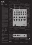
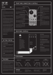
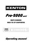
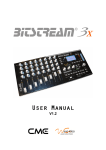
Fig.1 Front Panel Features
Master Clock
The master clock consists of the TEMPO knob, the rotary switch labeled DIVISION, the three-way slide
switch with which you select the main sync source and the large black push button with the blue LED ring
around it on the front edge of the pedal. The button can either be used a Start/Stop button, as the tap
button and/or to re-sync the master clock in certain situations.
The TEMPO knob is only active in FREE mode and can be used to freely adjust the main tempo anywhere
from 40bpm to 240bpm (beats per minute). The main clock output labeled CLOCK on the patch bay sends
a square wave signal every beat with a duty cycle of 50%.
The DIVISION knob can be used to send a division or multiples of the master CLOCK output. This ranges
from 16th notes to once every full bar – in reference of the master clock beats. The DIVISION output also
sends a square wave signal and has a duty cycle of 50%.
The three way switch next to the DIVISION knob has three positions: TAP which allows you to use the
large black push button to tap in a certain tempo. Also this is the position for syncing the pedal to an
external analog clock through the EXT. CLOCK input. The FREE position can be used to freely set the main
tempo of the pedal with the TEMPO button. The EXT. position serves as your choice i.e. if you want the
pedal to sync to either MIDI or DIN Sync input.
LFO
The LFO (low frequency oscillator) consists of four basic features. With the two way switch on the right
you can choose between synced or free running mode. The RATE knob sets the speed of the LFO. If you
chose to have the LFO synced to the master clock you can select a division or multiples of the master
tempo to sync to. If the LFO is running in free mode you can set any speed between 0.25Hz and 260Hz.
The SHAPE knob determines the output wave of the LFO. You can choose between sine wave, triangle,
square, sample and hold, and a special waveform which is composed of a sine wave and digital noise.
The SYMMETRY knob is used to wave shape the LFO output. You can bend the symmetry of the wave from
10% to 90%. More information can be found in the LFO section of this manual.
Envelope Generator
The envelope generator of the RH301 provides the opportunity to have another CV source available for
syncing devices and creating in-time events. It is built much like its well-known ancestors the ADSR
envelopes. In addition to ATTACK, DECAY, SUSTAIN, RELEASE there is also a RANGE knob with which you
can change the length of each segment as well as the behaviour of the envelope. The RANGE knob not only
KOMA Elektronik RH301 – Rhythm Workstation / Utility Tool
Page 4
stretches the maximum time each segment can take up but also crossfades between linear and logarithmic
behaviour while fluctuating from shorter to longer envelope times.
The envelope can either be synced to the master clock, the master division or can re-trigger itself in loop
mode. It can also be synced to an external gate signal.
Large Black Push Button
The large black push button on the front left corner has different functions. If in TAP mode, it is used to tap
in the tempo: Just tap the button three times and the new tempo will be adjusted to the tapped tempo. In all
other modes and when you use an external analog clock input to sync the pedal, this knob is used to send
start/stop signals over MIDI and DIN Sync.
Sensor
One of the features on your RH301 that you won't find in any other pedal is the possibility to control the
features of the pedals with the on board motion controller. Since its functions with infra red LEDs we call it
the SENSOR. The motion controller can be used in many different ways. Technically speaking, it emits a CV
signal (control voltage) which can be patched up with any CV receptive socket on the KOMA pedals and f.i.
on your modular system. By moving your hand over the sensor you can control the parameters of the CV
input you patched it up to. With the trimmer on the back of the pedal (it says SENSOR) you can change the
sensitivity of the motion controller. For more information about control voltage, check out the section
Control Voltage Theory of this manual.
KOMA Elektronik RH301 – Rhythm Workstation / Utility Tool
Page 5
OPERATION
The RH301 enables you to accomplish a couple of different tasks, including converting clock signals from
different formats into other formats. The RH301 can work with and be synced to analog clocks, MIDI and
the DIN Sync format.
For most applications it is necessary to achieve two things: First, sync the tempi of two or more pieces of
gear so that they are running at the same speed. The second thing you need to achieve is to have the two
synced tempi run in phase, i.e. let them start running at the same time. These two steps are solved
differently in the three clock formats that the RH301 is compatible with.
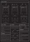
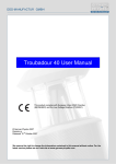
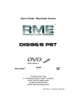
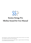
Fig. 2 The difference between MIDI, DIN Sync and Analog Clock Signals
MIDI is a digital communication standard from the 80s, coming in the flavor of a serial protocol. With MIDI
clock the clock signal itself consists of 24 pulses (called 'ticks') per quarter note to sync the tempi together.
For a synchronized start and stop of sequencers, LFOs or other functions, start and stop bytes are sent
over the same cable.
DIN Sync is an even older synchronization possibility from pre-MIDI ages. It usually uses 24 pulses
(sync24 – seldom sync48, sync96 or even sync192) per quarter to sync tempi together. For the
synchronized starting and stopping of devices a gate signal is used. If the gate is high it means start/run,while
if it is low, it means stop.
KOMA Elektronik RH301 – Rhythm Workstation / Utility Tool
Page 6
With analog clocks the matter is also pretty straight forward: The clock signal consists of a pulse or
square wave that syncs the tempi. Starting and stopping can be solved through various approaches, most of
them include a start/stop gate.All of the previously mentioned standards have been brought together in the
RH301 to provide a usable working environment, no matter what setup you use.
MIDI as the master sync source
Set the master sync source to EXT. and plug the MIDI cable with the clock signal into the DIN/MIDI IN jack
on the back of the pedal. The RH301 internally starts to adjust its tempo to the MIDI tempo as soon as a
clock signal arrives on the input.
A start / stop byte from your DAW or hardware MIDI sequencer is translated into a corresponding byte,
and only the MIDI clock itself is received by the pedal, start / stop gate on the DIN OUT jack. If no start /
stop byte, and only the MIDI clock itself is received by the pedal, the black push button can be used to start
itself and send a start / stop gate at the DIN OUT and to add a start / stop byte at the MIDI OUT jack.
The push button can also be used to sync “off beat”: If you push it while the RH301 is running already the
pedal will reset its internal clock to 0, in sync with the MIDI ticks that are coming via the MIDI cable. This
way you can manually sync the RH301 into shifted clock signals.
DIN Sync as the master sync source
If you want to sync your setup to a DIN Sync source simply plug in the cable and switch the master sync
source to EXT. The usage is similar to having your pedal synced to a MIDI signal. An incoming start / stop
gate is translated into a corresponding start / stop byte on the MIDI OUT connection. If no start / stop gate
is being received by the pedal, you can create your own by pressing the black push button. This will start the
pedal and send a MIDI start / stop byte to the MIDI OUT jack as well as a start / stop gate to the DIN
OUT jack.
The push button can also be used to sync “off beat”: If pushed while the RH301 is running, the pedal will
reset its internal clock to 0, but stays in sync with the DIN sync clock that is coming in via the DIN sync
cable. This way you can manually sync yourself into shifted clock signals.
Analog Clock as the master sync source
Set the master sync source to EXT. and insert a jack with a clock signal into the EXT. CLOCK jack on the
patch bay. The pedal reacts to rising edge clock signals going from 0V to at least 3V. You can use the black
push button to send start / stop bytes (MIDI) and start / stop gates (DIN) on the next rising edge trigger.
The EXT. CLOCK input is a switching type jack that overrides the other sync settings, so whenever you
insert a cable in this input the pedal will only sync to an analog clock / trigger signal on this jack.
RH301 as the master sync source
If you want the RH301 to be the master clock source itself there are two possibilities: You can set the
master clock to FREE and adjust the tempo with the TEMPO knob. By pressing the black push button you
create the start / stop functions.You also have an option to set the master clock to TAP, then using the black
push button to tap a tempo. After the third tap a start byte and gate are being created automatically.
KOMA Elektronik RH301 – Rhythm Workstation / Utility Tool
Page 7
LFO
AND
ENVELOPE GENERATOR
LFO
The LFO provided on the RH301 is the perfect companion for the clock syncing functions described earlier.
If you have your gear running in sync it gives you an extra CV source that can automatically be synced to
the master clock or a division/multiple of it. The output of the LFO as well as the inverted LFO is 0V – 7.6V.
The LFO has four easy to understand controls:
With the RATE knob you adjust the frequency of the LFO. If it's running in sync mode with the master clock
you can choose between the various divisions and multiples of the master tempo. If the LFO is running in
free mode you can change the frequency continuously from 0.25Hz to 260Hz. The LFO is not intended to
be used as a proper voltage controlled oscillator; it does not respond with 1 octave per volt and in the
higher frequencies the stability is less than 100%.
While the LFO is in sync mode, it will always need one bar in order to adjust to the newly set division after
you haven chosen a new division.
The SHAPE dial lets you choose between the five different waveforms of the LFO: sine, triangle, square,
sample and hold (S&H), and a special waveform which is composed of a sine wave and digital noise.
With the SYMMETRY knob you can bend the waveform. The wave shaping is wavetable based so it will not
be linear for the sine wave and the triangle. For the square wave the SYMMETRY acts like a pulse width
modulation; it ranges from 10% duty cycle to 90% duty cycle. For the S&H output the symmetry adds noise
to the LFO signal. For the “noisine” waveform the symmetry knob changes the noise level.
The SYMMETRY knob has a dent at the 50% setting, so it is easy to find the original, non-shaped waveforms.
Take your time and try the waveforms separately and change the symmetry to get an idea of what you're
changing.
LFO RANGE and SYMMETRY can be modulated by external CVs as well (see Control Voltage Theory
section for more information on that). Please keep in mind that the incoming CV signal (LFO SPEED input)
acts as if you would turn the potentiometer from fully counter-clockwise (CCW) to fully clockwise (CW),
so a rising CV signal from 0V – 5V gets you through the divisions from fast to slow in sync mode but gets
you from a low frequency to the fastest one in Hz mode.
Here is a table for the CV if you want to change your LFO division precisely:
CV
:16
:8
:4
:3
0V– 0.55V
0.56V-1.1V
1.11V-1.65V 1.66V-2.2V
:2
x1
2.21V-2.75V 2.76V-3.3V
x2
x3
3.31V-3.85V 3.86V-4.4V
x4
4.41V-5.0V
Envelope Generator
The RH301 also comes with an envelope generator onboard. For the most part it is a classic ADSR
envelope generator with the addition of the RANGE knob. The RANGE knob is used to scale the time
ranges of the ATTACK, DECAY and RELEASE stages. Simultaneously the behavior of the envelope is
changed from linear to logarithmic. The output of the envelope ranges from 0V – 7.6V.
SUSTAIN is not affected by the RANGE knob as its time is solely affected by the envelope gate. If the
envelope generator is synced to the master clock or the division, the gate is high for exactly 50% of the
corresponding beat.
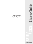
The RANGE knob scales the time ranges of the attack, decay and release stages from 3ms – 400ms to 40ms
– 4s. At the same time the response curve of the envelope changes gradually from linear to logarithmic, so
you have a snappy linear envelope in the shorter times and a more organic feeling envelope with longer
times.
You can trigger the envelope externally through the ENV GATE input, either with a trigger or a gate signal.
KOMA Elektronik RH301 – Rhythm Workstation / Utility Tool
Page 8
The only difference is in the sustain stage: If the external input is still high in the sustain stage the envelope
will be held until the gate falls low again and will then proceed to the release stage. If you trigger the
envelope with an external trigger the SUSTAIN knob simply determines the level that the envelope falls to
between the decay and release stages.
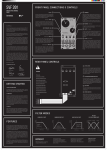
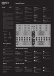
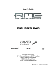
Fig. 3 The difference between linear and logarithmic ADSR output signals, normal and inverted.
KOMA Elektronik RH301 – Rhythm Workstation / Utility Tool
Page 9
CONTROL VOLTAGE THEORY
The concept of control voltage (CV) is not hard to understand: Instead of turning a knob on your pedal, you
simply connect a voltage – the control voltage – to the corresponding CV input that does the job for you.
So for example if you want to have a quickly varying LFO SYMMETRY you don't have to turn that knob all
the time, back and forth until your fingers fall off, but simply connect an alternating CV to the LFO
SYMMETRY input.
You can use control signals from any source to manipulate certain
features of the RH301. All of the CV inputs of the RH301 accept
bipolar as well as unipolar control voltages, but work best with CV
from 0 – 5V. The incoming CV signals are mixed together with the
corresponding knob on the RH301 itself and we provide you with a
attenuator for each CV input on the backside of the panel.
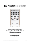
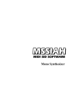
Fig.4 Backpanel Features
If you notice a significant distortion or clipping in your control signal waveform or strange CV behavior
simply turn the attenuator counter-clockwise (towards the word 'CV') until you hear your desired result. By
turning it counter-clockwise you attenuate the incoming CV signal. Fully counter-clockwise means that the
incoming CV signal is completely gone, whereas fully clockwise means that the incoming CV signal is arriving
to the circuit unattenuated. Furthermore you can set an offset voltage to your control voltage to adjust the
CV signal to your needs. The offset voltage is set by the corresponding knob on the front panel (LFO RATE
and LFO SYMMETRY). There's also a distinction between bipolar and unipolar signals. This is best explained
with a few pictures:
So, what happens? The incoming CV signal is shifted around the voltage that you select with the
corresponding knob. Example: if you insert a -5V to +5V sine wave into the LFO SYMMETRY CV jack you
will get the following results while turning the SYMMETRY knob:
A similar thing happens to unipolar CV signals: Their point of origin (0V) is shifted by the amount set with
the corresponding knob. In other words:You add the voltage of your knob to the voltage of your incoming
unipolar CV signal. Now that you know more about CV, let's see what the patch bay has to offer!
KOMA Elektronik RH301 – Rhythm Workstation / Utility Tool
Page 10
PATCH BAY AND REAR CONNECTIONS
Fig. 5 Patch Bay Features
The patch bay consists of fourteen 1/4” jack sockets which you can use to receive and send various control
voltage signals. If an arrow is pointing towards the jack socket it shows you that this is an output, if the
arrow is pointing away from the jack socket it is an input.
Let's start from left to right in the upper row.
CLOCK (analog clock output)
This is the main clock output of the RH301. It sends a 50% duty cycle square wave signal. The
tempo is dependent on various settings explained above. The CLOCK output is twofold and
both outputs are buffered.
DIVISION (analog clock output)
This is the division output, sending a 50% duty cycle square wave signal depending on the
setting of the rotary DIVISION switch. The DIVISION output is twofold and both outputs are
buffered.
EXT. CLOCK (analog clock input)
This CV input accepts rising edge driven analog clock signals. Every time a signal rises from
0V – 3V the pedal counts one beat.
LFO SPEED (CV input)
The LFO SPEED CV input controls the speed of the LFO, therefore plugging a CV signal into
this jack will change the speed of the LFO. When you insert a control voltage into this input
the RATE knob determines the offset voltage (see Control Voltage Theory section). (Usable
range from 0 – 5V).
LFO RESET (CV input)
The LFO RESET input can be used the externally reset the LFO to bar 1 at any time. The
input reacts to any rising edge trigger that changes from 0V to 3V.
Left to right, lower patch bay row:
ENV (CV output)
The ENV CV output holds the signal of the envelope generator. Signal ranges from 0V – 7.6V.
ENV INV (CV output)
The ENV INV CV output is the inverted envelope output. Signal ranges from 7.6V – 0V.
LFO (CV output)
This is the main LFO output of the pedal. The LFO can be shaped and set up in the LFO
section of the pedal. Signal ranges from 0 – 7.6V.
KOMA Elektronik RH301 – Rhythm Workstation / Utility Tool
Page 11
LFO INV (CV output)
This is the inverted LFO output of the pedal. It is in phase with the main LFO output but the
voltages are inverted. Signal ranges from 7.6V – 0V.
LFO SYMM (CV input)
The LFO SYMM CV input controls the symmetry of the LFO. When you insert a control
voltage into this input the SYMMETRY knob determines the offset voltage (see Control
Voltage Theory section). Usable range from 0 – 5V.
SENSOR (CV output)
This is the CV output of the infrared motion sensor. The closer you move something towards
the sensor, the higher the CV rises. The sensor output is 0 – 9V.
Back Panel connections:
DIN/MIDI IN (Clock / data input)
Socket for MIDI or DIN Sync clock input. The RH301 can distinguish if, and consequently,
which signal is present at this connection, so that you don't have to worry about different
settings.
MIDI OUT (Clock output)
This is the connection for the outgoing MIDI signal. It contains the clock information as well
as start and stop signals for MIDI receptive devices.
DIN OUT (Clock output)
This is the clock output for DIN Sync receptive devices. It provides the clock information
(sync24) as well as the start/stop gate.
MIDI THRU (Data)
This is the unprocessed MIDI signal present at the MIDI input jack chained through.
EXT SYNC
The EXT SYNC input is basically a way to externally "press" the large black pushbutton.
Every time a rising edge trigger (or gate) arrives at this input, the RH301 will react as if the
pushbutton on the pedal would have been pressed. You can use this input to externally
start/stop the RH301 when in FREE mode, re-sync it when in EXTERNAL mode and even
use it to externally tap a tempo in the pedal when in TAP mode.
CV ATTENUATORS (Trim-pot)
There is one CV input trimmer each for LFO Symmetry and LFO Rate. Turn the trimmer
fully CW to get 100% signal going through and turn the trimmer fully CCW to get no
incoming CV signal.
9V DC CONNECTOR
Standard BOSS Style adapter (2.1 x 5.5mm barrel plug), 9V, center polarity negative, 500mA
minimum. Only use the KOMA Elektronik power supply shipped with this pedal.
UPDATING FIRMWARE
The RH301 provides the possibility of updating its firmware by sending ('dumping') MIDI SysEx data through
a MIDI cable connected to the DIN/MIDI input on the back of the pedal. To get into firmware update mode,
unplug the power cable as well as any other connections on the patchbay or back panel jacks. Press and
hold the large black pushbutton while re-connecting the power cable. Keep holding the button for 2
seconds. If executed correctly, the blue light around the pushbutton should now steadily glow blue. Connect
a MIDI cable between the DIN/MIDI input on the back panel of the RH301 and your MIDI host. The RH301
is now ready to receive firmware updates. For more detailed information on this topic and the latest
firmware please check out the RH301 product page on www.koma-elektronik.com
KOMA Elektronik RH301 – Rhythm Workstation / Utility Tool
Page 12
EXAMPLES
In the example above, a computer running DAW software is the provider of the master clock signal.
In the example above, a drum computer with DIN Sync Out is providing the master clock signal.
KOMA Elektronik RH301 – Rhythm Workstation / Utility Tool
Page 13
KOMA Elektronik RH301 – Rhythm Workstation / Utility Tool
Page 14
TROUBLESHOOTING
I connected my DAW to the RH301 via MIDI but the pedal doesn't seem to start.
Firstly, make sure that you set the master clock sync source to EXT and there is no cable in the EXT.
CLOCK input on the patch bay. Please make sure that your DAW is sending the correct MIDI signals. The
RH301 expects a MIDI clock signal, not a MIDI time code. Furthermore, your DAW should send a start
signal whenever you hit play. Sometimes it can happen that programs only send a start signal in the beginning
of a song, not every time when you hit Play – for example in Ableton Live you should try to set “MIDI Clock
Type” to “Pattern”.
Your RH301 also won't start to sync to MIDI when there is a cable plugged into the EXT. CLOCK jack on
the patchbay – even if no clock signal is present at that input.
Also, check your MIDI cables. A large percentage of problems with MIDI sync are arising from cheap or
broken MIDI cables. If you have the opportunity, try different MIDI cables.
My LFO will randomly reset while syncing to external clock signals.
Please check your MIDI/DIN Sync/analog clock connections. Many problems arise from cheap or broken
cables. Also be sure that you don't accidentally modulate your LFO rate via a CV signal attached to LFO
SPEED and keep in mind that if you do so, the LFO needs one bar to adjust to the new tempo.
Some of my equipment is starting to hum when I attach a MIDI cable.
This can happen in some setups, mostly involving USB MIDI interfaces or other equipment with a USB
MIDI connection (sound cards, hardware MIDI controllers, etc.). Try to prevent ground loops and check
your MIDI connections – did we already mention that a lot of problems come from cheap or broken MIDI
cables?
When I connect my drum machine to the DIN OUT of the RH301 it starts and stops
randomly.
Please check the DIN cable that you use. Like with MIDI, most of the problems stem from defective or
wrong DIN cables. Make sure that all the pins on the cable are connected from one end to the other. With
some cheap MIDI cables it can happen that only the pins used for MIDI are actually connected through the
cable. MIDI and DIN use the same cable and plug but not the same pins on that cable.
I patch my sensor the the CV inputs and it doesn't seem to change anything.
Make sure you use the correct PSU (9V, 500mA, center polarity negative) for the sensor to work correctly.
Have a look at the back of the pedal and check if your CV attenuators are in the right setting. Furthermore
keep in mind that the incoming CV signal is added to the corresponding knob on the frontpanel (LFO RATE
and LFO SYMMETRY) and you won't hear your changes if they are set too high.
I set my RH301 to FREE mode / EXT. mode and sync to an external clock signal but
my DAW/synthesizer/drum machine doesn't start playing.
The RH301 converts incoming start / stop signals from MIDI to DIN Sync. If, however, you miss those
start/stop signals or none are sent you have to create them yourself by pressing the large black pushbutton.
When you are in FREE mode you always have to press that pushbutton yourself, if you are syncing to an
analog clock input you also have to create your own start / stop signal.
KOMA Elektronik RH301 – Rhythm Workstation / Utility Tool
Page 15
SOME NICE TRICKS
Here are some neat tricks that you might find useful while using the RH301 in different contexts:
Create in-sync falling edge triggers (S-Triggers)
Some synthesizers – especially older Korg, Moog and Yamaha ones – expect so-called S-Triggers on certain
trigger inputs. The 'S' stands for switching. In contrast to most modern trigger inputs these expect the signal
to go from high to low. If you come across such a situation it might come in handy to set the LFO to square
wave and connect the inverted LFO output to the S-Trigger input. Set the LFO to sync mode, turn the LFO
symmetry fully CCW to be on-beat, and turn it clockwise to add a groovy feeling to it.
Rhythmically change the LFO division pattern
Take a standard 1/4” patch cable and connect it from the envelope output to the LFO speed input. Set both
LFO and envelope generator to sync and create a slowly changing envelope. The envelope will change the
LFO division in a rhythmical manner. Pattern mayhem!
LFO – Envelope Ping Pong
Take a standard 1/4” patch cable and connect it from the inverted LFO output to the envelope gate input
(ENV GATE). Set the LFO to SYNC and chose the square wave shape. Play around with the LFO symmetry
knob. Your envelope will now start its cycle every time the LFO just went low, so they are playing in a nice
ping-pong way but still in sync with the rest of the clock signals.
More tips!?
You'll find an constantly updated overview of tips and tricks on our website!
Like your RH301!?
Check out our other products on www.koma-elektronik.com
and follow us on Facebook: www.facebook.com/KOMAelektronik
KOMA Elektronik RH301 – Rhythm Workstation / Utility Tool
Page 16
TECHNICAL SPECIFICATIONS
GENERAL
Casing:
Powder coated aluminum casing, silk screened text and wooden side panels
Dimensions:
23 cm x 20 cm x 5 cm (L x W x H) / 9″ x 9.8″ x 2″ (L x W x H)
Net. Weight:
1000 gr / 2.2 lbs
Shipping Weight:
1.5 kg. / 3.3 lbs including power adapter and this instruction manual
Power requirements:
9V DC power adapter, 500mA min, center polarity negative (only use the KOMA
adapter shipped with the pedal)
FEATURES
TEMPO
Rotary control to set the tempo in Free mode
DIVISION
Rotary switch to select one of 9 divisions/multiples of the master clock signal
SOURCE SELECT
Slide switch to select the master clock sync source (Tap – Free – MIDI / DIN
Sync / external analog clock synchronization
RATE
Rotary control to change the speed / division of the LFO
SHAPE
Rotary switch to change the basic waveform of the LFO. Available waveforms are:
Sine – Triangle – Square – S&H - Noisine
SYMMETRY
Rotary control to change the symmetry of the LFO waveform
LFO MODE
Slide switch to chose between synced or free running mode for the LFO
ATTACK
Rotary control to set the attack time of the envelope
DECAY
Rotary control to set the decay time of the envelope
SUSTAIN
Rotary control to set the level of the envelope while the gate is high
RELEASE
Rotary control to set the release time of the envelope
RANGE
Rotary control to change the time range on the A, D and R stages. By turning this
knob clockwise the envelope becomes slower and fades from a snappy linear to a
logarithmic behavior
ENVELOPE MODE
Slide switch to chose between master clock sync – division sync – free running
mode
MASTER TEMPO LED LED ring around the Tap/Start/Stop button
LFO LED
LED indicator to display the LFO
ENVELOPE LED
LED indicator to display the envelope
LARGE BLACK
BUTTON
Acts as a tap button in Tap mode or as Start / Stop in the other master clock
modes
2 IR EMITTERS, 1 IR Calculates the distance between an object and the pedal and generates a CV signal
RECEIVER
according to the measured distance. The CV output of this sensor appears as a CV
output on the patch bay, from where you can route it to the CV input of your
desired, to-be-modulated feature
PATCH BAY INS AND OUTS
CLOCK (x2)
Master clock output; square wave signal with 50% duty cycle
KOMA Elektronik RH301 – Rhythm Workstation / Utility Tool
Page 17
DIVISION (x2)
Division output; square wave signal with 50% duty cycle
EXT. CLOCK
CV input that accepts any rising edge trigger or gate
LFO SPEED
CV input (0 – 5V) to control the rate / division of the LFO
LFO RESET
Trigger/Gate input that resets the LFO on the rising edge
ENV
CV output of the envelope signal (0 – 7.6V)
ENV INV
CV output of the inverted envelope signal (7.6V - 0V)
ENV GATE
CV input for an external envelope gate or trigger
LFO
CV output for the LFO signal (0 – 7.6V)
LFO INV
CV output for the inverted LFO signal (0 – 7.6V)
LFO SYMM
CV input for controlling the symmetry of the LFO waveform
SENSOR
CV output (0 - 8V) of the onboard motion sensor for usage with CV inputs on the
pedal, other KOMA Elektronik pedals or other voltage-controlled devices
All patch bay inputs and outputs are mono ¼ inch phone jacks.
BACKPANEL
DC POWER INPUT
Accepts standard BOSS style 9V power adapters, center polarity negative, 500mA
min. (KOMA Elektronik power adapter included)
CV ATTENUATORS
The sensitivity of the CV inputs can be attenuated with trimmers on the back.
DIN/MIDI IN
Combined DIN Sync / MIDI input
MIDI OUT
MIDI Output
DIN OUT
DIN Sync out
MIDI TRHU
MIDI Thru provides the unprocessed MIDI signal present at the DIN/MIDI IN jack
EXT SYNC
CV Input for an external gate or trigger to externally start/stop the RH301 in the
different operating modes.
KOMA Elektronik RH301 – Rhythm Workstation / Utility Tool
Page 18
WARRANTY
KOMA Elektronik warrants its products to be free of defects in materials / workmanship and conforming to
specifications at the time of shipment for a period of two years from the date of purchase. During the
warranty period any defective products will be repaired or replaced at KOMA Elektronik's option on a
return-to-factory basis. This warranty covers defects that KOMA Elektronik determines are no fault of the
user.
Returning Your Product?
You must obtain prior approval in the form of an RMA (Return Material Authorization) number from
KOMA Elektronik before returning any product. Email us at [email protected] to request the
RMA number . All products must be packed carefully and shipped with the power adapter supplied by
KOMA Elektronik.
Sorry, the warranty will not be honored if the product is not properly packed. Once you have received the
RMA#, write it on the box together with the word: WARENRÜCKSENDUNG and carefully pack your
product, ship the product to KOMA Elektronik with transportation and insurance charges paid, and include
your return shipping address.
What will we do?
Once received, we will examine the product for any obvious signs of user abuse or damage as a result of
transport. If the product has been abused, damaged in transit, or is out of warranty, we will contact you with
an estimate of the repair cost. Warranty work will be performed and KOMA Elektronik will ship and insure
your product to your address free of charge.
How to initiate your warranty?
Please initiate your warranty online by sending an email to
[email protected]!
IMPRINT
KOMA Elektronik GmbH
Mahlower Strasse 24
12049 Berlin-Neukölln
Germany
Vertretungsberechtigter Geschäftsführer / Managing Director: Wouter Jaspers, Christian Zollner
Sitz der Gesellschaft / Registered Office: Berlin, Germany
Registergericht / Court of Registration: Amtgericht Berlin-Charlottenburg
Registernummer / Registration Number: HRB 145453
Umsatzsteuer ID / VAT ID Number: DE285522050
KOMA Elektronik RH301 – Rhythm Workstation / Utility Tool
Page 19