1
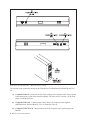
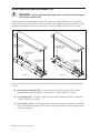
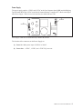
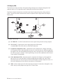
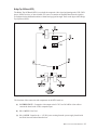
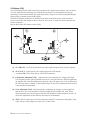
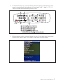
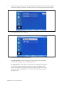
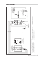
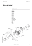
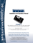
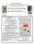
Contents
Glossary of Terms..............................................................................................................................3
Overview ...........................................................................................................................................4
Wide Screen Overhead Interface - Model BI and Model TVO.........................................................5
Internal Components (Model BI and Model TVO).........................................................................8
Power Supply............................................................................................................................9
VGA Adapter (VAB)...............................................................................................................10
Bridge Tap Off Board (BTO).................................................................................................. 11
Wide Screen Overhead Interface - Model CI...................................................................................12
Internal Components (Model CI)..................................................................................................13
Maintenance of Wide Screen Overheads.........................................................................................15
General Cleaning...........................................................................................................................15
Vent Holes.....................................................................................................................................15
Adjustments...................................................................................................................................15
Configuring Samsung Overhead Monitors for Direct Control.........................................................16
Cable Diagrams................................................................................................................................19
Widescreen Overhead Monitors 1
Intentionally Blank Page
2 Widescreen Overhead Monitors
Glossary of Terms
To better understand the information presented in this section you should better familiarize yourself with
these terms.
Bridging Tap-Off PCB (BTO) - A circuit board used split the composite video signal originating at the
VCR, DVD player, satellite receiver, or other suitable A/V source.
Composite Video - The originating at a VCR, DVD player, satellite receiver, or other suitable A/V
source.
RGBS (Red, Green, Blue, Sync) - A format of video describing the way in which the video is sent over
the cable.
TV-Only Monitor - A monitor that is used to display only the video sent from a VCR or other suitable
composite video source. This monitor cannot display bowler’s scoresheet.
VGA Adapter Board - A circuit board used to convert the scoresheet video signal sent to the widescreen
(LCD) overhead through Cat5 cabling so that it can be displayed on the monitor.
Widescreen Overhead Monitors 3
Overview
Brunswick Wide Screen overhead monitor packages come in three configurations; Brunswick supplied
LCD Wide Screen monitors, bowling center supplied off-the-shelf monitors, and bowling center
supplied off-the-shelf SCART monitors (Europe).
With Brunswick supplied the LCD monitors, the center is able to turn the monitors on/off and switch
the scoring monitor between the scoresheet and TV video through either the control desk or by using
the remote control that comes with the monitors. A TV-Only monitor is also an option. These monitors
connect to the scoring system through a Wide Screen Overhead Interface. The Scoresheet monitor used
a Model BI interface while the TV Only monitor uses the Model TVO interface.
If a bowling center supplies their own wide screen monitors, the Brunswick scoring system converts the
signal from the Scoring Computer so that it can be displayed on the monitors. On/Off control and video
switching between the scoresheet and TV video must be done from the remote control that comes with
the monitor or if the monitor supports it, through a cable connected to a serial connection at the back of
the monitor. The bowling center is responsible for running any TV signal to the monitors. This type of
monitor connects to the scoring system using the Wide Screen Overhead Interface - Model CI.
For European installations a bowling center supplied monitor with a SCART interface can be used. On/
Off control of these monitors (from the front desk) may be available if the monitor responds to the 12V
signal on the SCART connector. Otherwise the remote control that was supplied with the monitor must
be used to control the power. Switching between the scoresheet and TV video is done through the
remote control that comes with the monitor. The bowling center is responsible for running their own
TV signal to the monitor. This type of installation is directly connected to the scoring system and does
not require the use of a Wide Screen Overhead Interface.
4 Widescreen Overhead Monitors
Wide Screen Overhead Interface - Model BI and Model TVO
The Wide Screen Overhead Interface comes in three versions or models; BI, CI, and TVO. For
Brunswick Installed LCD monitors models BI and TVO are used.
The Model BI interface is used for the scoresheet monitors and can adapt both scoresheet and TV video
signals. Control of the monitor is accomplished through a cable connected directly to the back of the
monitor.
Model TVO is used for the TV-Only monitors. It allows for the display of the TV video and control
of the monitor power. It does not provide the scoresheet video signal. Refer to the figures titled Wide
Screen Overhead Interface - Model BI direct control and Wide Screen Overhead Interface - Model TVO
direct control.
(3)
COMPOSITE VIDEO
TO LCD
(7)
SCORER VIDEO
TO LCD
(6)
SCORER
VIDEO IN
(2)
COMPOSITE VIDEO
OUT
ER
(1)
COMPOSITE VIDEO
IN
T
OU
W
PO
PO
ER
W
IN
(5)
POWER
OUTPUT
(4)
POWER INPUT
AND FUSES
Wide Screen Overhead Interface - Model BI direct control
Widescreen Overhead Monitors 5
Wide Screen Overhead Interface - Model TVO direct control
The function of the connections located on the Wide Screen Overhead Interface Models BI and TVO
are:
(1) Composite Video In - Connection for the video coming from a composite video source located
at the control desk or prior Scorer Interface Module. The video source is usually a VCR, DVD
player, or Satellite Receiver.
(2) Composite Video Out - Connection that “daisy chains” the composite video signal to
additional Scorer Interface Modules. See (1) Composite Video In.
(3) Composite Video To LCD - Output connection for the composite video signal going to the
Monitor.
6 Widescreen Overhead Monitors
(4) Power Input and Fuses - Voltage receptacle where main power enters the Module. The input
voltage can be 110VAC - 240VAC module. An access door at the bottom of the main power
receptacle houses 5 amp, Slo-Blow fuses to protect the incoming power.
POWER OUT
PO
ER
W
T
OU
ER
IN
W
PO
POWER IN
ER
IN
W
PO
Fuse Holder - Wide Screen Overhead Interface for Brunswick LCD Monitors
(5) Power Output - Voltage receptacle for the Monitor Power.
(6) Scorer Video In - An RJ-45 or DB-15 connection for the scorer video coming from the scorer
computer. This connector is not present on the TV-only Interface.
(7) Scorer Video To LCD - Output connection to the LCD monitor for the converted scorer video.
This connector is not present on the TV-only Interface.
Widescreen Overhead Monitors 7
Internal Components (Model BI and Model TVO)
WARNING!
Always disconnect the main power cable prior to servicing the
inside of the interface box.
The difference between Model BI and Model TVO interfaces is Model BI contains a VGA Adapter
Board (VAB) that provides conversion of the scoresheet video coming from the scorer computer. Refer
to the figure titled Wide Screen Overhead Interface (Internal) - Models BI and TVO direct control .
(1)
COMPOSITE VIDEO
BRIDGING TAPOFF PCB
(57-500454-000)
(1)
COMPOSITE VIDEO
BRIDGING TAPOFF PCB
(57-500454-000)
(4)
VGA ADAPTER BOARD
(57-500700-000)
(2)
POWER SUPPLY PCB
(57-500469-000)
CO
M
VID PO
E SIT
LCO TOE
D
(2)
POWER SUPPLY PCB
(57-500469-000)
SC
VIDOR
EOER
LC TO
D
MODEL B1
MODEL TVO
Wide Screen Overhead Interface (Internal) - Models BI and TVO direct control
The function of the circuit boards located inside the Wide Screen Overhead Interface Models BI and
TVO are:
(1) Bridging Tap-Off Board (BTO) - A circuit board used split the composite video signal
originating at the VCR, DVD player, satellite receiver, or other suitable A/V source.
(2) Power Supply PCB - The Power Supply PCB converts the incoming 120VAC or 240VAC to
+12VDC, -12VDC, and +5VDC
(4) VGA Adapter (VAB) - Circuit board used to convert the scoresheet video signal coming from
the scorer computer through the CAT5 cable to a VGA signal so that it can be displayed on the
Wide Screen monitor.
8 Widescreen Overhead Monitors
Power Supply
The power supply supplies +12VDC and -12VDC to the Sync Separator board (SSB) and the Bridging
Tap Off board (BTO) and +5VDC to the Serial Communications Controller (SCC). Refer to the figure
titled Power Supply - Wide Screen Overhead Interface Models BI and TVO.
(1)
POWER IN
(2)
POWER OUT
Power Supply - Wide Screen Overhead Interface Models BI and TVO
The function of the connectors on the Power Supply are:
(1) Power In - Main power input of 120VAC or 240AC.
(2) Power Out - +12VDC , -12VDC, and +5VDC DC power out.
Widescreen Overhead Monitors 9
VGA Adapter (VAB)
The board converts the scoresheet video signal coming from the scorer computer through the Cat5
(ethernet) cable to a VGA signal that can be displayed by the Wide Screen monitor. .
Equilization and gain adjustments are included on the board to adjust the quality of the scoresheet
picture. In most cases these controls do not need to be adjusted. Refer to figure titled VGA Adapter
Board (VAB).
VGA Adapter Board (VAB)
(1) J1 VIDEO IN - An RJ-45 connection for the video signal coming from the scoring computer.
(2) J2 VGA OUT - Connection for video signal going to the LCD monitor.
A standard DB15 VGA-VGA cable is used for this connection.
(3) Equalization Adjustment (VR1) - Adjustment used to compensate for changes in the high
level frequencies of the video signal that can occur if a video cable that is a different length than
the supplied 150’ cable. When adjusted properly the video will appear crisp. If out of adjustment
the video can appear “smeared” or have a ghost image. In most cases adjustments of this control
is not needed or recommended.
(4) Gain Adjustment (VR2) - Adjustment used to compensate for changes in video signal level
that can occur if a video cable that is a different length than the supplied 150’ cable. When
adjusted properly the video will appear with the same brightness as that of adjacent screens. In
most cases adjustments of this control is not needed or recommended.
(5) JPR3 - Selects whether power for the board comes from the J3 connection or through the video
cable. Always set this jumper across pins 2 & 3 (Video Cable).
10 Widescreen Overhead Monitors
Bridge Tap Off Board (BTO)
The Bridge Tap Off Board (BTO) is used split the composite video signal originating at the VCR, DVD
player, satellite receiver, or other suitable A/V source. It contains an amplifier that allows the signal to
be continued to the additional monitors without loosing signal strength. Refer to the figure titled Bridge
Tap Off Board (BTO).
Bridge Tap Off Board (BTO)
The functions of the connectors and components on the BTO board are:
(1) J1 VIDEO TO TV - Composite video output to the LCD. Use a RCA-RCA video cable to
connect the board to the LCD’s composite input.
(2) J2 +/- 24V IN - Not Used
(3) J3 +/- 12V IN - Input for the +/- 12V DC power coming from the power supply board inside
the Wide Screen Overhead Interface box.
Widescreen Overhead Monitors 11
(4) J4 COMPOSITE VIDEO OUT - Composite video output to the next BTO board in the
daisy-chain. If the video signal does not continue a 75 ohm terminator must be installed on the
connector. This is done at the last BTO board in the chain.
(5) J5 COMPOSITE VIDEO IN - Composite video input from composite source (VCR, DVD,
etc.) or previous BTO board in the daisy-chain.
(6) JPR2 Ground “commoning” jumper - This jumper is used to determine if the power supply
ground or the shield of the coaxial cable will be used for the ground signal between the board
and the video source. Set this jumper so that pins 2 and 3 are shorted or remove the jumper
from the board. Do not place the jumper at pins 1 and 2 unless you are requested to so by
Brunswick.
(7) D4 +9V - This LED is lit when the board is generating +9V power.
(8) D5 -9V - This LED is lit when the board is generating -9V power.
NOTE: Both LEDs (D4 and D5) should be lit when the board has power.
Wide Screen Overhead Interface - Model CI
The Wide Screen Overhead Interface - Model CI is used for bowling center supplied Wide Screen
monitors. The model CI interface converts the video originating at the scorer computer to a standard
VGA signal. Control of the monitor’s power and switching between video inputs must be done using
the remote control that came with the display. Refer to the figure titled Wide Screen Overhead Interface
- Model CI.
(1)
SCORER
VIDEO IN
(2)
SCORER VIDEO
TO LCD
Wide Screen Overhead Interface - Model CI
The function of the connections on the Wide Screen Overhead Interface Model CI are:
(1) Scorer Video In - Input connection for the scorer video coming from the scorer computer.
(2) Scorer Video To LCD - Output connection to the LCD monitor for the converted scorer video.
12 Widescreen Overhead Monitors
Internal Components (Model CI)
WARNING! Always disconnect the main power cable prior to servicing the
inside of the interface box.
The internally the Model CI Interface contains a Sync Separator Board (SSB) that allows it to convert
the scoresheet video coming from the scorer computer so that the monitor can display it. Refer to the
figure titled Wide Screen Overhead Interface (Internal) - Models CI .
(1)
VGA ADAPTER BOARD
Wide Screen Overhead Interface (Internal) - Models CI
(1) VGA ADAPTER BOARD
Widescreen Overhead Monitors 13
VGA Adapter (VAB)
The VGA Adapter Board (VAB) converts the scoresheet video signal coming from the scorer computer
to a VGA signal that can be displayed by the Wide Screen monitor. The board adapts the video by
generating a vertical and horizontal sync signal based on the voltage levels of the incoming RGB signal
and providing a common ground for the signals.
Equilization and gain adjustments are included on the board to adjust the quality of the scoresheet
picture when a cat5 cable longer (or shorter ) than 150 feet is used. In most cases these controls do not
need to be adjusted.
Refer to figure titled VGA Adapter Board (VAB).
VGA Adapter Board (VAB)
(1) J1 VIDEO IN - An RJ-45 connection for the video signal coming from the scoring computer.
(2) J2 VGA OUT - Connection for video signal going to the LCD monitor.
A standard DB15 VGA-VGA cable is used for this connection.
(3) Equilization Adjustment (VR1) - Adjustment used to compensate for changes in the high
level frequencies of the video signal that can occur if a video cable that is a different length than
the supplied 150’ cable. When adjusted properly the video will appear crisp. If out of adjustment
the video can appear “smeared” or have a ghost image. In most cases adjustments of this control
is not needed or recommended.
(4) Gain Adjustment (VR2) - Adjustment used to compensate for changes in video signal level
that can occur if a video cable that is a different length than the supplied 150’ cable. When
adjusted properly the video will appear with the same brightness as that of adjacent screens. In
most cases adjustments of this control is not needed or recommended.
(5) JPR3 - Selects whether power for the board comes from the J3 connection or through the video
cable. Always set this jumper across pins 2 & 3 (Video Cable).
14 Widescreen Overhead Monitors
Maintenance of Wide Screen Overheads
Although the monitors require very little maintenance, it is suggested that you follow the
screen manufacturer’s recommendations to keep them running at optimum performance. As
each manufacturer has their own maintenance requirements, it is impossible to give specific
recommendations for monitors supplied by a bowling center. Always check with the manufacturer of
your monitor before using any cleaning solution or glass cleaner.
In general, it is important to make sure that any vent holes are clear of obstructions and the monitors are
adjusted and cleaned for optimum readability.
General Cleaning
Clean the LCD monitor surface with a lint-free, non-abrasive cloth. Avoid
using any cleaning solution or glass cleaner unless the manufacturer specifically recommends their use.
Vent Holes
Keep the vent holes on the back of the LCD clean of dirt and dust. It is recommended to wipe holes
with a soft cloth a minimum of once per year. If using the internal cooling fan continuously, it’s
recommended to wipe vent holes a minimum of once a month.
Adjustments
Adjust the monitor’s brightness, contrast and sharpness controls to enhance readability. Refer to the
monitor vendor manual for specific adjustment procedures.
Widescreen Overhead Monitors 15
Configuring Samsung Overhead Monitors for Direct
Control
When the Samsung overhead monitors are directly connected and controlled from the scorer computer
rather than through a Serial Communication Controller (SCC) board, the scorer computer and the
monitor must be configured as follows:
1. At the scorer “configuration menu,” configure the scoring computer to use the Samsung LCD
overhead communication by selecting Direct Monitor Ctrl”. Refer to figure titled Configuration
Menu.
Configuration Menu
Scoring Computer #
1
First Lane
1
Number of Lanes
8
Password
Calibrate
Direct Monitor Ctrl
******
Pinsetter
GS
AMF/ No SS
String
Other
5,0,0,0258
Configuration Menu
16 Widescreen Overhead Monitors
OK
OH Type
NTSC
PAL
LCD
PAL/TV
Cancel
2. At the monitor being set up, press the following buttons in sequence on the Samsung remote
control, to reset the monitor and enable the on-screen display: “OFF”, “Mute”, “1”, “8”, “2” ,
“Power”. Refer to figure titled Samsung Remote Control.
Samsung Remote Control
3. When the monitor turns on, a menu will appear on screen. Use the down arrow on the remote
control to scroll down to “Reset”. Press “Enter” on the remote to reset the monitor.
Widescreen Overhead Monitors 17
4. If needed, turn the monitor “on”. Press the “Menu” button on the remote control, then using the
down arrow button, scroll down to the “Multi Control” icon located at the bottom of the menu.
5. Press right arrow to select “ID Setup”
6. Set the ID Setup of the monitor as follows:
Scoresheet monitors - Set the ID Setup to the lane number where the monitor
is located. The example above is configured for lane 1.
TV-Only monitors - Set the ID for TV-only monitors sequentially starting with
the next number after the total number of lanes (scoresheet monitors) in the
center. For example if the number of lanes in the center is 16, the first TV-Only
monitor will be have the ID setup of 17. The next TV-Only monitor will have
the ID of 18, etc..
18 Widescreen Overhead Monitors
3
1
J2
J3
(2)
57-500700-000
VGA ADAPTER BOARD
J1
(1) 57-500454-000 COMPOSITE VIDEO
(2) 57-500700-000 VGA ADAPTER BOARD
BRIDGING TAPOFF AMPLIFIER PCB
(4) 11-686557-000 POWER OUTLET
(5) 11-686559-000 POWER INLET
Wide Screen Overhead Interface Model BI Wiring
(1)
57-500454-000
COMPOSITE VIDEO
BRIDGING TAPOFF
AMPLIFIER, PCB
(3)
57-500469-000 POWER SUPPLY
(3)
57-500469-000
POWER SUPPLY
(5)
11-686559-000
POWER INLET
(4)
11-686557-000
POWER OUTLET
Cable Diagrams
Widescreen Overhead Monitors 19
20 Widescreen Overhead Monitors
(3)
57-500469-000
POWER SUPPLY
(1) 57-500454-000 COMPOSITE VIDEO
(2) 11-686559-000 POWER INLET (3) 57-500469-000 POWER SUPPLY
BRIDGING TAPOFF AMPLIFIER PCB
(4) 11-686557-000 POWER OUTLET
Wide Screen Overhead Interface Model TVO Wiring
(1)
57-500454-000
COMPOSITE VIDEO
BRIDGING TAPOFF
AMPLIFIER, PCB
(2)
11-686559-000
POWER INLET
(4)
11-686557-000
POWER OUTLET
(1)
OUTLET
(3)
POWER
SUPPLY
(1)
OUTLET
(2)
OUTLET
A/C Power input to Power Supply (57-500500-000)
(1) OUTLET
(2)
INLET
(1)
BRIDGING TAP OFF
AMPLIFIER PCB
J1
(3)
POWER SUPPLY
(2)
POWER SUPPLY
J3
DC Power Harness
(1) BRIDGING TAPOFF AMPLIFIER PCB j1
(1)
TO CABLE
(2)power supply j3
(2)
TO SSC
Communication Extension Cable 50’ (57-500528 -000)
(1) TO CABLE
(2) TO SSC
Widescreen Overhead Monitors 21
(1)
DB-15 MALE
(2)
S.C.A.R.T. CONNECTOR
1
15
2
11
3
7
4
20
5
6
6
8
7
NC
8
NC
16
9
1,2,3,
10,12
9
10
5
11
17
12
4
13
18
NC
14
15
14,19
NC
SHIELD
NC
Scorer Video Cable – Scorer Computer to SCART Monitor (57-500552 -000)
(1) DB-15
(2)s.c.a.r.t. connector
(1)
(2)
Communication Extension Cable 15’ (57-500554 -000)
(1) TO CABLE
(2)
TO SCC
(2)
TO J1 ON
VGA ADAPTER BOARD
(VAB)
(1)
TO SCORING
COMPUTER
CAT5e Widescreen Video Cable (Ethernet Cable) (Part No. 57-500256-150)
(1) TO SCORER COMPUTER
22 Widescreen Overhead Monitors
(2)
TO J1 ON VGA ADAPTER BOARD (VAB)