1
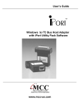
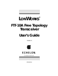
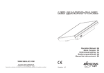
Model 2804: Professional
Distribution Solution (PDS) 110
Channel Transmitter
Installation Guide and User Manual
IOM2804
Revision 5.2, November 2005
Warning
The optical emissions from the chassis and connected optical fiber are laser-based and may present eye hazards. Follow all safety precautions
Technical Support
If you encounter any kind of problem after reading this manual, contact your local distributor or a Force, Inc.
Applications Engineer. To reach technical support:
On the Web:
http://www.forceinc.com
USA (800) 732-5252
By Phone (Monday through Friday 8:00 am to 5:00 pm EST):
TEL (540) 382-0462
By Fax:
(540) 381-0392
By Email:
[email protected]
825 Park Street, Christiansburg, VA 24073 • USA (800) 732-5252• TEL (540) 382-0462 • FAX (540) 381-0392 • [email protected] • www.forceinc.com
© 2005 by Force, Inc. Force reserves the right to make changes to the product described in this document in the interest of product improvement.
Model 2804 Professional Distribution Solution (PDS) 110 Channel Transmitter
Contents
User Manual
3.5 Cleaning17
3.5.1 Optical Connector Cleaning Equipment17
3.5.2 Directions for Optical Connector Cleaning18
Prefaceii
Section 1 Product Technical Bulletin1
1.1 Product Overview1
1.2 FCC Notice1
3.5.3 Connector Handling18
3.6 Troubleshooting18
3.7 Problems and Comments19
Index21
1.3 Optical, Video, Electrical Characteristics2
1.4 Environmental and Physical Characteristics2
1.5 Specification Notes2
Figure 1.1 In-Band Frequency Response of the 2804T
and 2808R Link2
Figure 1.2 Expanded Frequency Response of the 2804T
and 2808R Link3
Figure 1.3 CNR vs. Rx Optical Input and Channel Loading
(2804T/2807R)4
Figure 1.4 Transmitter Level per Channel vs. Number of
Channels5
Figure 1.5 Transmitter Level/Channel vs. Log10 (Number
of Channels)5
Figure 1.6 Response of Model 2804 RF Power Meter6
Figure 1.7 Top Label Used to Determine RF Input for
Transmitter6
1.6 Applications7
Figure 1.8 Professional Distribution Solution with Return
Path7
1.7 Part Numbers8
Section 2 Installation Instructions9
2.1 General Installation Requirements9
2.2 Items Provided9
2.3 Items Required9
2.4 Inspection10
2.5 Equipment Rack Configuration10
2.6 Measuring RF Input Levels at the Transmitter10
2.7 Connections11
2.8 Front Panel Physical Description12
Figure 2.1 Transmitter Front Panel12
2.9 Rear Panel Physical Description13
Figure 2.2 Transmitter Rear Panel13
2.10 Safety Precautions13
2.10.1 Laser Safety Procedures13
2.11 Shipping and Handling Precautions14
2.12 Storing the Unit14
Section 3 Operating Instructions15
3.1 Connections and Power-up15
3.2 Performance Verification16
3.3 User Maintenance17
3.4 Repair Service17
2
IOM2804 Revision 5.2
Model 2804 Professional Distribution Solution (PDS) 110 Channel Transmitter
User Manual
Product Specifications
Optical and Video Characteristics: @ 25 °C, SM Fiber (Note 1)
Min.
Channel Loading
Bandwidth
Operating Wavelength
Optical Output Power (P/N ends in /06)
Optical Output Power (P/N ends in /08)
Optical Output Power (P/N ends in /10)
Optical Output Power (P/N ends in /12)
Optical Output Power (P/N ends in /13)
Required Fiber Bandwidth
Input/Output Impedance
Side Mode Suppression Ratio (SMSR)
Backreflection Tolerance
Carrier-to-Noise Ratio (CNR)
Composite Second Order (CSO)
Composite Triple Beat (CTB)
Input Signal Range (per ch.)
40
1290
Typ.
1310
+6
+8
+10
+12
+13
Max.
Units
110
870
1330
Ch.
MHz
nm
dBm
dBm
dBm
dBm
dBm
MHz
Ohms
dB
dB
2,000
75
30
-50
See Figure Figure 3
-65
-69
See Figures 4 and 5
Notes
2
3
3
3
3
3
4
5
dB
dB
6, 7
Electrical Characteristics
Min.
Typ.
Max.
Units
Notes
Power Supply Voltage
120
240
VAC
8
Power Supply Frequency
Power Dissipation
Fuse (Slow-Blow)
50
60
Hz
Watts
A
8
9
Units
Notes
25
1.25
Physical Characteristics
Min.
Weight
Physical Dimensions
3
Typ.
Max.
5.5
2.5
19 W x 1.72 H x 14.1 D
483 x 44 x 358
lbs.
kg
in.
mm
IOM2804 Revision 5.2
Model 2804 Professional Distribution Solution (PDS) 110 Channel Transmitter
User Manual
Environmental Characteristics
Min.
Operating Temperature Range
Storage Temperature Range
Humidity (RH, non-condensing)
Typ.
0
-20
0
Max.
Units
Notes
+45
+70
90
°C
°C
%
10
Specification Notes
1) The Model 2804 has been tested and found to comply with the limits for a Class A digital device, pursuant
to Part 15 of the FCC Rules. These limits are designed to provide reasonable protection against harmful
interference when the equipment is operated in a commercial environment. This equipment generates,
uses, and can radiate radio frequency energy and, if not installed and used in accordance with the instructions in this manual, may cause harmful interference to radio communications. Operation of this equipment in a residential area is likely to cause harmful interference, in which case the user must correct the
interference at the their own expense. Compliance with applicable regulations depends on the use of
shielded I/O cables. The user is responsible for procuring the appropriate cables.
2) Figure Figure 1 shows the typical frequency response of a 2804 link over the specified frequency range.
The gain flatness is typically ±1.0 dB over this range. The flatness is typically less than ±0.1 dB over a
standard 6 MHz channel bandwidth. See Application Note AN123 for additional information on North
American Television Frequencies.
10
Response (dB)
5
0
-5
-10
-15
-20
0
1
2
2804T
with 2807R
3
5
7
6
4
Frequency (Hundreds MHz)
8
9
10
2804T with
2808R
Figure 1 In-Band Frequency Response of the 2804T and 2808R Link
4
IOM2804 Revision 5.2
Model 2804 Professional Distribution Solution (PDS) 110 Channel Transmitter
User Manual
Figure Figure 2 shows an expanded view of the frequency response of a typical 2804T/2808R link.
10
8
6
Response (dB)
4
2
0
-2
-4
-6
-8
-10
40
122
204
286
368
450
532
614
696
778
860
Frequency (MHz)
2804T
with 2807R
2804T with
2808R
Figure 2 Expanded Frequency Response of the 2804T and 2808R Link
3) All optical power levels are average values. Output is Class IIIb laser.
4) Be sure to compute your fiber bandwidth (end-to-end) as well as attenuation.
The Model 2804 incorporates an optical isolator in the laser package that reduces the effect of optical
backreflections on the laser performance. However, all analog lasers are affected by optical backreflections. The 2804 can only achieve published performance levels if the fiber between the transmitter and
receiver has a maximum optical backreflection of -50 dB. Optical backreflection levels above -50 dB will
increase the noise floor of the laser (i.e. decrease the carrier-to-noise ratio), worsen both CSO and CTB
performance, increase passband ripple, and dramatically increase cross modulation. The result will be a
noisy, grainy picture with diagonal bars.
Force, Inc. recommends that all fiber connections be SC/APC type, FC/APC type or fusion spliced. There
is some folklore which suggests that the only critical backreflection is the one closest to the transmitter.
Our experience does not support that view. We find that all backreflections matter, regardless of their distance from the transmitter.
IOM2804 Revision 5.2
5
Model 2804 Professional Distribution Solution (PDS) 110 Channel Transmitter
User Manual
5) Figure Figure 3 presents a tremendous amount of performance data for the 2804 link. The horizontal axis
is the amount of optical light that reaches the receiver. (It is not the loss between the transmitter and
receiver.) The vertical axis shows the carrier-to-noise ratio at a given optical input level.
Figure 3 CNR vs. Rx Optical Input and Channel Loading (2804T/2807R)
Typical transmitter output is +10 dBm, so a received optical power of +2 dBm corresponds to an optical
loss of 8 dB. The vertical scale is the carrier-to-noise (CNR) ratio. Six curves are plotted against these
axes. The top curve is the typical result when only 5 channels are transmitted through the link. It can be
seen that very high CNR results and in fact the output is quite usable with receiver optical inputs as low as
-12 dBm, corresponding to 22 dB of optical loss! As the channel loading gets higher, the maximum achievable CNR drops.
Note that the link CNR is usually specified for a received optical power of
-3 dBm or more. Thus, a 2804TK-SCAP/12 optical transmitter, with an optical output of +12 dBm, will
provide optimal performance with up to 15 dB of optical loss at full channel loading. If lower channel loading is used, then the link can operate at higher optical losses and still provide exceptional CNR.
6) The recommended RF input level is shown in Figures 4 and 5.
WARNING
Exceeding the recommended RF input level may instantaneously destroy the transmitter.
Both figures show the same information, the transmitter level per channel versus the number of channels
being transmitted; however, in Figure Figure 5 the horizontal scale is a logarithmic scale. This shows that
the underlying relationship is linear if plotted against the logarithm of the number of channels.
6
IOM2804 Revision 5.2
Model 2804 Professional Distribution Solution (PDS) 110 Channel Transmitter
User Manual
Figure 4 Transmitter Level per Channel vs. Number of Channels
Figure 5 Transmitter Level/Channel vs. Log10 (Number of Channels)
Figure Figure 6 shows the response of the Model 2804 transmitter’s integral RF power meter. This meter
is accessed via pin 5 of the 9-pin D-sub connector on the rear of the transmitter.
IOM2804 Revision 5.2
7
Model 2804 Professional Distribution Solution (PDS) 110 Channel Transmitter
User Manual
Figure 6 Response of Model 2804 RF Power Meter
7) Each transmitter has a label such as the one shown in Figure 7 that gives the RF input levels for the transmitter. The individual carrier levels should closely match each other to ensure consistent performance on
all channels. In all cases, set the composite RF input level so that the RF INPUT LEVEL LED is green.
The RF indicator LED only operates properly for rated channel loading and a flat input spectrum. To use
the chart, look up the channel loading you will be presenting to the transmitter input and read off the drive
level per video carrier. For instance, with 40-channel loading, each video carrier should be about +25
dBmV.
Figure 7 Top Label Used to Determine RF Input for Transmitter
8) The Tx rear panel power module can accept voltage levels from 120 to 240 VAC at 50 to 60 Hz.
8
IOM2804 Revision 5.2
Model 2804 Professional Distribution Solution (PDS) 110 Channel Transmitter
User Manual
9) Fuse Rating is 1.25A, Slow-Blow.
CAUTION
Risk of fire. Only use fuses with same type and rating as marked.
10) Most parameters are relatively unaffected by varying temperature. A moving air environment is recommended at ambient temperatures above +35°C.
11) The CATVLinx® VSB/AM Fiber Optic Link is optimized for single-mode operation only. Use on multimode
fiber is not recommended, even for short distances, because of the large amount of modal noise that could
result.
IOM2804 Revision 5.2
9
Model 2804 Professional Distribution Solution (PDS) 110 Channel Transmitter
User Manual
Installation and
Operation
General Installation Instructions
The installation of these units is very simple. There are no special unpacking instructions, except that care
should be taken to handle units gently. Fiber optic links are sensitive electronics devices that should be handled with care. Like most electronics, they are susceptible to ESD. Proper ESD techniques, such as wearing a
wrist grounding strap, should be observed at all times when handling a unit. The units should not be dropped.
No assembly is required.
Do not install the equipment near sources of excessive heat, such as furnace outlets or above heat producing
units, such as large power supplies and tube-type equipment. Observe temperature and relative humidity
requirements specified in Section , page 4.
WARNING
Potentially hazardous uninsulated voltages exist beneath the top panel.
Items Provided
The following is a list of items provided with each Model 2804 PDS Fiber Optic Video Transmitter:
Qty.
Mfr.
P/N
AR
Force, Inc.
2804TX-SCXX/XX
Description
1 per connector
Any
Any
Active Device Receptacle Cap for Optical and RF Connectors
2 per unit
Force, Inc.
2804.342-2
L-Bracket Mounting Ears. Allows the table top Tx chassis to
be adapted to a 19" wide rack.
1 per unit
Any
Any
Qty.
Mfr.
P/N
CATVLinx 110 Ch. PDS Transmitter
®
Three-wire ground AC power cable.
Items Required
10
Description
AR
Force, Inc.
2807RX-SFXX
CATVLinx PDS/PNS Mini-node CATV Receiver
AR
Force, Inc.
2808RX-SFXX
CATVLinx® PDS/PNS CATV Receiver
4 per unit
Any
Any
6-32 Panhead Mounting Screws with Lock Washers and
Nuts (used to mount receivers)
1
Any
Any
Straight Screwdriver
AR
Any
Any
EIA standard 19" rack with hardware to install the transmitter into the rack.
®
IOM2804 Revision 5.2
Model 2804 Professional Distribution Solution (PDS) 110 Channel Transmitter
Qty.
Mfr.
P/N
AR
Any
Any
1 per 2807
Force, Inc.
PS200
1 per 2808
Any
Any
User Manual
Description
9/125 µm Single-mode Fiber
Wall-mount Power Supply (Model 2807R only)
Three-wire ground AC power cable.
Front Panel Physical Description
A. Mounting Brackets (Optional, included): Adapts the 1RU transmitter
chassis for use in a EIA standard 19" wide rack.
B. Handles: For easy removal and installation of 1RU chassis with
mounting brackets into a 19" wide rack.
C. Key-Lock Power Switch: Turns the unit on and off, preventing accidential power down.
D. Power Indicator LED (Green LED): The LED is on when the unit is receiving AC power and off when there is no power to the unit.
E. Start Up LED (Yellow LED): Lit for the first 10-15 seconds after power-up. During this period, the laser is not powered, giving the laser
cooler circuit time to stabilize.
F. RF Input Level LED (Tri-colored Green/Yellow/Red LED): This LED indicates the RF signal input level into the transmitter. The RF input indicator is green when the RF signal input is within ±1.5 dB of the
optimum input level. When the signal input falls below the optimum
±1.5 dB range, the LED becomes yellow. When the signal input rises
above the optimum range, the LED turns red. See the warning label
WARNING
DO NOT EXCEED THE RECOMMENDED RF INPUT LEVEL.
EXCESSIVE LEVELS OF RF INPUT WILL DESTROY THE TRANSMITTER.
NOTE
Normally, this LED will be red or change from red to green in
the first ten seconds after power has been applied to the
transmitter. If the LED turns red at any time other than in the
first ten seconds of operation, the unit should be turned off
IMMEDIATELY to avoid laser damage.
H. Overheat Status LED (Red LED): Lights red to indicate operation
above normal operating temperature range. See Optical, Video, Electrical Characteristics: @ 25 °C, SM Fiber (Note 12), page 2 for normal operating temperatures or contact factory. When the unit detects
an OVERHEAT condition, the laser will be turned off. The unit must
cool and power must be cycled to restore operation.
I. Laser Stable LED (Blue LED): When lit, the unit is operating normally.
J. LED Readout (Blue, 7-Segment): The control knob sets the transmitter LED readout display to one of four parameters: RF Input Levels (in
dBmV), Laser Cooler Current (in Amps), Laser current (in mA), and
Laser Temperature (in degrees Farenheit). The LED display then
shows transmitter parameters.
K. RF Test Point: Allows the user to test the RF signal level using an RF
test meter.
on top of the unit (Figure 1.7, page 6) for instructions on acheiving
the recommended RF input level.
G. Cooler Status LED (Bi-colored Green/Red LED): When green, this
LED indicates that the laser cooler (TEC) is functioning normally, and
the laser temperature is stable.
Figure 8 Transmitter Front Panel
(Dimensions in parentheses are in millimeters.)
IOM2804 Revision 5.2
11
Model 2804 Professional Distribution Solution (PDS) 110 Channel Transmitter
User Manual
Rear Panel Physical Description
A) Heat Sink: Dissipates excess heat from the transmitter.
B) RF Input (F Connector): RF signal input into the transmitter. Warning
label below advises not to exceed the RF input level, or the transmitter
may be destroyed.
C) Optical Output (FC/APC or SC/APC): Optical output from the transmitter. A dust cover should be placed over the connector when not in
use.
WARNING
CAUTION
Connect only to a three-wire grounded outlet. Do not defeat
the purpose of this ground. The fuse type is 1.25A, Slow
Blow.
F. Unit Serial Number: The unit serial number is a code that identifies the
product’s warranty start date. See page iii for Force’s standard warranty.
OPTICAL LASER RADIATION IS PRESENT AT THE TRANSMITTER’S CONNECTOR WHEN THE UNIT IS TURNED ON.
AVOID DIRECT EYE EXPOSURE TO THE INVISIBLE BEAM.
D) Status Output (DB9 Connector): Transmitter remote status monitoring connection. See Section Figure for pin connections.
E) AC Power Input and Fuse Holder: Connects to primary AC power via
Figure 9 Transmitter Rear Panel
(Dimensions in parentheses are in millimeters.)
Inspection
Remove the unit from its shipping container. Any in-shipment damage that may have occurred should be visually apparent. Look for bent or damaged connectors or mounting brackets. Claims for damages incurred in
shipment should be made directly to the transportation company in accordance with their instructions. Save
the shipping cartons until installation and performance verification are completed.
Equipment Rack Configuration
Carefully unpack the chassis, and install it in your earth grounded equipment rack. Make sure to load the
heaviest equipment near the bottom of the rack and the lightest equipment at the top of the rack. The surface
of the equipment rack that mates to the chassis mounting ears should be conductive. The unit should be
located in an area that provides adequate lighting and is relatively free from dust. The units are each housed in
a single EIA standard 1RU (1.75 inch) rack-mount chassis. To ensure the unit does not overheat, leave 1RU of
space above and below each installed chassis. When connecting power to the chassis, take care as to not overload the branch circuit supplying power to whatever is already connected. Also, make sure there are no
obstructions in the fan exhaust or inlet paths.
12
IOM2804 Revision 5.2
Model 2804 Professional Distribution Solution (PDS) 110 Channel Transmitter
User Manual
Measuring RF Input Levels at the Transmitter
Excessive RF input to a fiber optic CATV transmitter WILL destroy the laser even if the unit is not powered.
Lasers can be destroyed by being overdriven for as little as one nanosecond (10-9 seconds). Because they can
be destroyed so quickly, it is essentially impossible to design a circuit or “fuse” that will blow before the laser is
destroyed. Therefore it is imperative that the RF level be within acceptable limits BEFORE the cable is
attached to the transmitter. See the “Drive Level per Video Carrier” top label (see Figure 1.7) on the transmitter for the optimum drive levels, and follow the steps below.
1) Using a spectrum analyzer, determine that the RF level input to the transmitter is within safety bounds.
The unit is shipped with a 20 dB attenuator on the input to protect against accidental overload on initial
hookup. (An additional 20 dB attenuator may be added for absolute security.) This attenuator should be
removed once RF levels are verified to be nominal.
2) The “Drive Level per Video Carrier” chart on top of the transmitter gives the nominal RF input level for
channel loading from 1 to 110 channels. Note that the chart is in dBmV units per channel, not dBm. DO
NOT exceed the values shown on the chart.
3) The “RF Input Level” LED on the front panel gives a positive indication of the RF level. If the LED is yellow, the RF level is too low. Increase in 2 dB steps until the LED turns green. If the LED is red, the RF
input level is too high. Disconnect the RF input immediately. Decrease RF levels by 6 dB steps and reconnect the RF input until the LED turns yellow or green. If it turns yellow, increase RF levels by 2 dB steps
until the LED turns green.
Ideally, the RF level should be checked with an instrument such as a spectrum analyzer to verify that the levels
are appropriate. If instrumentation is not available to actually measure the RF levels, Force recommends adding 40 dB of attenuation at the transmitter input; 40 dB of attenuation will adequately protect the unit from the
highest RF levels that might be seen in a typical CATV installation. Do not attach the RF cable at this time,
just verify the RF levels and/or add the appropriate attenuators at the transmitter input.
Connections
Connector Name
RF Input
Optical Output
Connector Type
F Type
RF input to the transmitter.
SC/APC (Std.), FC/APC*
Optical output from the transmitter
(Option)
It is imperative that backreflections be controlled to very low levels.
9-Pin D-Sub
Status Output
Connector Function
Pin
Function
1
2
3
4
5
6
7
8
9
+5 V Power
RF Level Status
Laser Status
TEC Cooler Status
RF Power Meter
Ground
Ground
Ground
Ground
Accepts a standard IEC power
Power Input
cord.
* Note: The FC/APC interface uses the “wide-key” standard. This means that the units are optimized for use with FC/
APC connectors that have a 2.14 mm wide alignment key. “Narrow-key” FC/APC connectors (2.02 mm), often referred
to as JDS compatible, may be used but will produce inferior results. Standard FC/PC connectors have a 2.36 mm wide
key and cannot be plugged into either unit.
Power
IOM2804 Revision 5.2
13
Model 2804 Professional Distribution Solution (PDS) 110 Channel Transmitter
User Manual
Safety Precautions
The optical emission from the units are laser-based and present eye hazards if improperly used. Never use any
kind of optical instrument to view the optical output of the unit. Complete laser safety procedures may be
downloaded at http://www.forceinc.com/techbull/laser-safety-procedures.pdf.
Operating Instructions
1) Install the links as described on page 10 of this document.
2) Measure the RF level BEFORE making any connections to the transmitter. This measurement is
described in Section , page 13.
3) Clean the optical connectors. Complete optical connector cleaning instructions may be downloaded from
http://www.forceinc.com/an.htm.
4) Connect the optical fiber to the transmitter and the receiver (see receiver IOM). Be sure that the fiber has
continuity and less than the maximum allowable optical loss. Also be certain that the fiber is the proper
size. This product can only be used with single-mode fiber. The input power to the Rx must be less than
+4.5 dBm. The units will not work back-to-back. The optical input level to the Rx can be ascertained by
checking the color of the “Optical Level” indicator LED on the Rx.
Red LED = Too much optical power
Green LED = Correct optical power level
Yellow LED = Not enough optical power
5) Connect the RF source (VCR, camcorder, cable television, etc.) to the RF input on the transmitter.
6) Connect the RF output on the receiver to the monitor input. The monitor input should present a 75 Ohm
impedance.
7) Connect the AC power cord to the back of the transmitter. The 2804T has the most complex startup
sequence of the Force CATV line. Because the laser is thermometrically cooled and is a high performance
item, the startup and stabilization sequence is 10-15 seconds long. The front panel of the 2804T has six
LED indicators. One is green only, one is yellow only, one is red only, one is blue only, and the remaining
two are tri-color LEDs. The normal startup sequence is as follows:
Action
Power LED
Start Up
RF Input
Cooler Status
Overheat
Laser Stable
Unit Off
Dark
Dark
Dark
Dark
Dark
Dark
Apply Power
Green
Yellow
Note 1
Red
Note 2
Dark
5-10 Sec.
Green
Yellow
Note 1
Green
Note 2
Dark
10-15 Sec.
Green
Dark
Note 1
Green
Note 2
Blue
Note 1: At any time, the RF input will be yellow if the RF input level is too low, green if it is within the nominal RF
input band, and red if the RF input is too high.
Note 2: At any time, if the box temperature is too high, the OVERHEAT LED will light. This will cause the LASER STABLE LED to go dark and the laser will power down. It will be necessary to cool the box and cycle power to restore
normal operation.
If the “RF Input Level” LED is red, this means the RF level is too high. DISCONNECT THE RF INPUT
IMMEDIATELY. Add the supplied RF attenuator, then reconnect the RF input and observe the LED
color. Adjust the RF input until the RF Input Level LED is green, indicating the optimum RF input level.
WARNING
OPTICAL LASER RADIATION IS PRESENT AT THE OPTICAL CONNECTOR WHEN THE UNIT IS ACTIVATED. AVOID
DIRECT EYE EXPOSURE TO THE BEAM.
8) Connect power supply to the receiver.
For Model 2807: The power supply must be from +12 to +16 Volts DC. It is critical that the supply voltage
never drops below +12 Volts. If the voltage drops below +12 Volts, the link may not operate. Force, Inc.
recommends the Model PS200 wall-mount power supply for use with the Model 2807 receiver.
For Model 2808: The Model 2808 receiver uses an integral AC power supply which uses a standard 3-wire
ground AC power cord.
14
IOM2804 Revision 5.2
Model 2804 Professional Distribution Solution (PDS) 110 Channel Transmitter
User Manual
For all receivers: When power is applied and the link is operational, the “Optical Level” LED should light
green to indicate the optimum optical input level. If the optical input level is too low, the LED will be yellow. The LED also doubles as a power indicator.
WARNING
OPTICAL LASER RADIATION IS PRESENT AT THE OPTICAL FIBER THAT ATTACHES TO THE RECEIVER’S OPTICAL CONNECTOR WHEN THE UNITS ARE ACTIVATED. AVOID DIRECT EYE EXPOSURE TO THE BEAM.
9) The units are now fully operational. Verify the proper operation of the link by following the steps in Section , page 15. The user may verify a number of performance parameters via the front panel LED display.
See Figure 2.1, page 12 for details. No other user adjustment or attention is required.
Performance Verification
Once the units have been installed, verify that the picture quality is good. If the picture quality is not good,
there are several likely causes:
1) The optical fiber may have large backreflections. Use an OTDR to examine the fiber run.
2) There may be non-APC optical connectors somewhere in the system. These cause unacceptable levels of
backreflection.
3) The RF input spectrum may not be flat. It is possible to have a green RF Level LED even if the input spectrum has a large amount of tilt. All Force CATV products are designed to operate with a flat input spectrum.
4) There may be extraneous (i.e., non-video) signals in the input RF. Be sure to filter out all non-desirable
signals.
5) The optical input power at the receiver may be too low. In this case, the receiver optical status LED will be
yellow. See Figure 1.3 for the expected CNR versus the channel loading and received optical power.
Troubleshooting
Common problems include lack of continuity in the optical fiber, lack of power (or reversed power), or
improper input levels. The units are designed to work with a 75 Ohm system. A number of indicator LEDs may
assist in troubleshooting. These allow the user to quickly assess the nature of any major unit malfunctions. If
problems persist consult the Force, Inc. reference materials listed below, or contact the factory.
Problems and Comments
Problem
No optical power out of Tx.
No optical power at the Rx.
IOM2804 Revision 5.2
Check
Comments
Verify that the AC power cord is firmly
attached to the back of the transmitter,
and verify the integrity of the power
If no AC power is reaching the unit, the
cord. Be sure that the primary power
“Power” LED on the transmitter will be
source has not been inadvertently
off. Check Tx power connection.
turned off and that no fuses have
blown in the unit or at the power
source. Plug in the power cord.
If the unit is receiving AC power
If the Tx “Laser” LED is red but the
(“Power” LED is green), check the
“Cooler Status” LED is green, try turn“Laser” LED. If this is red, check the
ing the transmitter off and back on. The
“Cooler Status” LED. If the “Cooler Sta“Laser” and “Cooler Status” LEDs
tus” LED is green, the problem may be
should light red within the first ten secin the laser. If the “Cooler Status” LED
onds of unit initialization and then turn
has also turned red, the TEC cooler has
green. If either of these LEDs remains
failed and the laser is in danger of
red, contact Force, Inc. for additional
overheating. Remove power from the
instructions.
unit immediately.
If there is power at the Tx, verify proper
Check power at the Tx.
fiber is connected to the Rx, and ensure
the integrity of the fiber.
15
Model 2804 Professional Distribution Solution (PDS) 110 Channel Transmitter
Problem
Check
Low optical power at the Rx
Check optical output power at the Tx.
No signal out of Rx.; “Optical Level”
indicator LED is either yellow, red or
unlit.
Verify the input signal at the Tx.
Signal out of Rx is distorted.
Verify input signal at Tx. The Tx “RF
Input Level” LED should be green.
Verify fiber size.
16
User Manual
Comments
If there is optical power out of the Tx,
verify that all optical connections are
APC type. Also, verify the integrity of
the fiber.
The Tx “RF Input Level” LED should be
green. If the LED is either red or yellow,
the signal input has fallen outside of
the ±1.5 dB range. If the Tx “RF Input
Level” LED is green, the receiver may
be in need of repairs. Contact the factory for additional instructions.
A larger signal will cause distortion,
and may destroy the transmitter. If the
RF level is too high, the LED will be red.
Adjust the input level until the LED turns
green.
Use single-mode fiber only.
IOM2804 Revision 5.2
Model 2804 Professional Distribution Solution (PDS) 110 Channel Transmitter
User Manual
Warranty and Return
Policy
Warranty
Force, Incorporated standard products are warranted to be free from defects in materials and workmanship,
meeting or exceeding factory specified performance standards for a period of three (3) years from date of purchase.
Force Obligations
Force will, at its discretion and expense, repair any defect in materials or workmanship or replace the product
with a new product. Force will, upon receipt of the return, evaluate the product and communicate to the customer the nature of the problem, and determine if the claim falls under warranty coverage.
If during the warranty period, Force is unable to repair the product to the original warranted state within a reasonable time, or if subcomponents of the unit have been obsoleted or discontinued, then Force has the option
to provide an equivalent unit.
Exclusions
This warranty does not extend to any product that has been damaged due to acts of God, accident, misuse,
abuse, neglect, improper system design or application, improper installation, improper operation or maintenance, or connection to an improper voltage supply.
The Force warranty does not cover fuses, batteries, and lamps. Modifications or alterations of Force products
(including but not limited to installation of non-Force equipment or computer programs), except as authorized
by Force, will void this warranty. Removal or breaking of the seals on the product will also void the warranty.
In addition, cost of repair by unauthorized persons within the warranty period of the product will not be covered by Force, Incorporated. Such repairs will void the warranty.
Force, Incorporated makes no other representation or warranty of any other kind, express or implied, with
respect to the goods, whether as to merchantability, fitness for a particular purpose, or any other matter.
Force, Incorporated’s liability shall not include liability for any special, indirect or consequential damages, or
for any damages arising from or attributable to loss of use, loss of data, loss of goodwill, or loss of anticipated
or actual revenue or profit, or failure to realize expected savings, even if Force, Incorporated has been advised
of the possibility of such damages. This warranty constitutes Force, Incorporated’s entire liability and the customer’s sole remedy for defects in material and workmanship.
17
IOM2804 Revision 5.2
Model 2804 Professional Distribution Solution (PDS) 110 Channel Transmitter
User Manual
Product Return Policy
Customers will be permitted to return products for credit, repair, or replacement only after receiving authorization from the Customer Service Manager (CSM) and only with a valid Return Material Authorization
(RMA) number. The criteria determining whether a product is covered under this policy are described below
and RMA numbers will be issued only under these guidelines. For Return Requests that do not comply with
the following criteria, the CSM must have approval from the VP Operations, or designee prior to issuing an
RMA number.
Products Returned for Credit - Non Distributor
Customers will be allowed to return product for credit only under the following conditions:
•
•
•
•
•
•
•
Products are current standard Force products as per the price list.
Products are in new, unused, and undamaged condition and are in the original packaging.
Products were originally shipped to the customer requesting Return Authorization.
Request for return is for a valid reason as determined by Force, Inc.
Products were shipped to the customer less than 3 months prior to return request.
Customer receives proper Return Material Authorization prior to returning the product.
Customer pays return freight and insurance if requested by Force, Inc.
Customers will be issued a credit for the original selling price of the product less a 20% restocking charge after
verification that the product meets the criteria as stated above. Payment to customers with no outstanding balance will be made 30 days after requested by customer.
Products Returned for Repair or Replacement
Force’s response to a customer product return request will be based upon whether or not the product is still
part of Force’s standard product offering and whether or not the product is still under warranty. A product will
be considered active if it is currently part of Force’s standard product offering. Active products are denoted in
Force’s current price list. Obsolete products are not considered active. A product is considered under warranty
in accordance with “Force, Inc. Product Warranty”
Prior to receiving an RMA number, the customer will be asked to discuss the reason for the return with Technical Support to try to resolve the problem. This discussion will be documented to aid with troubleshooting and
repair of the product. Any detail the customer can provide will expedite the process once the product is
received.
The criteria denoted above will cause any incoming returns to fall into one of the following categories:
A. The product is currently active and is under warranty.
B. The product is currently obsolete, but is still under warranty.
C. The product is active, but out of warranty.
D. The product is obsolete and out of warranty.
Active Product Under Warranty
Force will honor the warranty for these products. As a result, product(s) should be accepted upon return for
rework or repair in accordance with Force’s warranty policy.
Obsolete Product Under Warranty
Force will honor the warranty for these products. As a result, product(s) should be accepted upon return for
rework or repair in accordance with Force’s warranty policy.
Active Out of Warranty
Force will accept return of product under this category as long as the sale of the product occurred less than five
(5) years prior to the return request. The product serial number should aid in determining the age in cases
where information is not in the data base. Rework or repair will be in accordance with Force’s warranty policy
and will include an evaluation charge, which will be quoted to the customer prior to the return of the product.
18
IOM2804 Revision 5.2
Model 2804 Professional Distribution Solution (PDS) 110 Channel Transmitter
User Manual
The evaluation charge is 20% of the current list price of the product or a minimum of $250 whichever is
greater. The customer will either need to provide a purchase order number (with approved credit) or a credit
card number before receiving an RMA number. Force cannot guarantee its ability to repair or rework the
product. If costs to repair the product exceed the evaluation charge, the customer will be notified of such
charges and instruction to proceed with repairs will be indicated either by a P.O. number or credit card authorization.
Obsolete Product Out of Warranty
Force is not obligated to accept requests for product under this category. The CSM, with prior approval from
Operations will be responsible for approving return requests for products falling under this category.
Receiving an RMA for Returns
Customers requesting RMA numbers for any reason will be instructed as to how and where to ship the products being returned, and will be directed to show the RMA number on all external packaging and documentation. The CSM is responsible for providing any necessary instructions to the customer to ensure proper
handling of the retuned material. Upon receipt of the product, all Force personnel are to process the return as
per SP002,”Handling of Customer Returns”. Contact the factory at USA (800) 732-5252 or TEL (540) 3820462 to request an RMA.
Shipping and Handling Precautions
The units are, in general, very rugged and can withstand the stresses of most shipping and handling circumstances. However, the following precautions should be taken:
1) When the units are shipped they should be wrapped in a protective material, such as bubble wrap, to protect against excessive jarring and to prevent damage to the external finish of the units. Always use packing
material to separate multiple units that are packaged together. \
2) Care should be taken not to drop or strike the units in any way, especially around the optical connectors.
3) The units should never be submersed in any liquid. SEVERE SHOCK HAZARD!
Storing the Unit
If a unit is to be out of use for an extended period of time, the following steps should be taken to ensure the
preservation of the unit:
1) The storage temperature range is -40°C to +60°C.
2) A low humidity environment is preferable for long term storage.
3) All connectors should be covered with active device receptacle caps.
IOM2804 Revision 5.2
19


![Rapport [2002-2] - GRIP - Groupe de Recherche et d`Information sur](http://vs1.manualzilla.com/store/data/006410304_1-e55e34bf657ace034fc7a605920322f3-150x150.png)