1
Operation Manual
FT1020G3
Rev 2.0
For Software V2.0.X
FT1020G3
Fire alarm system
MA430
April 2013
This page has deliberately been left blank.
Operation Manual
FT1020G3 Rev 2.0
Table of Contents
1
Introduction________________________________________________________ 7
1.1
Overview ------------------------------------------------------------------------------------------------- 7
1.2
Definitions------------------------------------------------------------------------------------------------ 7
1.2.1
Alarm points ......................................................................................................... 7
1.2.2
Smoke detector .................................................................................................... 7
1.2.3
Analogue detector (sensors)................................................................................. 7
1.2.4
Analogue detector (Sensor) Base (ASB)............................................................... 8
1.2.5
Conventional detector .......................................................................................... 8
1.2.6
Conventional Detector Base (CDB) ...................................................................... 8
1.2.7
Addressable ......................................................................................................... 8
1.2.8
Conventional zone line input / Detector circuit....................................................... 8
1.2.9
Output unit ........................................................................................................... 8
1.2.10
Output / Control output ......................................................................................... 8
1.2.11
Short circuit isolator (ISO) .................................................................................... 8
1.2.12
Remote Display Unit (RDU) .................................................................................. 8
1.2.13
COM loop............................................................................................................. 9
1.2.14
Control Unit / C.U. / C.I.E. .................................................................................... 9
1.2.15
Fire Brigade Panel (FBP) ..................................................................................... 9
1.2.16
Control panel (CP) ............................................................................................... 9
1.2.17
System................................................................................................................. 9
1.2.18
LED ..................................................................................................................... 9
1.2.19
External Indicator LED (RIL) ................................................................................. 9
1.2.20
Display / LCD ....................................................................................................... 9
1.2.21
Door open ............................................................................................................ 9
1.2.22
Site Specific Data (SSD) .................................................................................... 10
1.2.23
Software (S/W) / System program ...................................................................... 10
1.2.24 Network / TLON® / LonWorks® / Echelon / Node / TLON Conn. board / Gateway /
Sub net / Backbone net / Router / Repeater...................................................................... 10
2
Overview _________________________________________________________ 11
2.1
The FT1020G3 system ----------------------------------------------------------------------------- 11
2.1.1
Printer ................................................................................................................ 11
2.1.2
Expansion boards .............................................................................................. 11
2.1.3
Power supply ..................................................................................................... 11
2.2
S/W versions ------------------------------------------------------------------------------------------ 11
2.3
Documents -------------------------------------------------------------------------------------------- 12
2.4
Applications ------------------------------------------------------------------------------------------- 12
2.5
PC programs ------------------------------------------------------------------------------------------ 12
2.5.1
EBLWin.............................................................................................................. 12
2.5.2
TLON Manager .................................................................................................. 13
1
Operation Manual
FT1020G3 Rev 2.0
2.5.3
3
EBLWeb Config tool ........................................................................................... 13
Control Unit _______________________________________________________ 14
3.1
FT1020G3 Specifications -------------------------------------------------------------------------- 14
3.2
FT1020G3 Limitations ------------------------------------------------------------------------------ 15
3.3
Control Unit Layout ---------------------------------------------------------------------------------- 16
3.4
LED indicators and push buttons ---------------------------------------------------------------- 17
4
Control Unit Options _______________________________________________ 22
4.1
Occupant Warning System (OWS) -------------------------------------------------------------- 22
4.2
Gaseous extinguishing system control module ----------------------------------------------- 24
4.2.1
Overview ............................................................................................................ 24
4.2.2
Display board (SUB929) & decal ........................................................................ 24
4.2.3
Control board (SUB928) ..................................................................................... 25
4.2.4
CIE interface board (SUB943) ............................................................................ 26
4.2.5
Inputs from FT1020G3 to CIE interface board (SUB943) .................................... 26
4.2.6
Outputs from CIE interface board (SUB943) to FT1020G3.................................. 26
4.3
1668 Fan control ------------------------------------------------------------------------------------- 27
4.4
Zone control module -------------------------------------------------------------------------------- 28
5
The display (LCD) __________________________________________________ 29
5.1
Areas in the display --------------------------------------------------------------------------------- 29
5.2
Symbol area ------------------------------------------------------------------------------------------- 30
5.3
The information area priority order -------------------------------------------------------------- 30
5.4
System information in the LCD ------------------------------------------------------------------- 31
5.4.1
6
User definable system information ...................................................................... 31
User level, User name & Password ___________________________________ 32
6.1
User level 0 -------------------------------------------------------------------------------------------- 33
6.2
User level 1 -------------------------------------------------------------------------------------------- 33
6.3
User level 2A ------------------------------------------------------------------------------------------ 33
6.4
User Level 2B ----------------------------------------------------------------------------------------- 34
6.5
User level 3A ------------------------------------------------------------------------------------------ 35
6.6
Access level 3B -------------------------------------------------------------------------------------- 35
6.7
Access level 4 ---------------------------------------------------------------------------------------- 35
7
Silence Alarm devices ______________________________________________ 36
7.1
SILENCE ALARM (inside switch) ---------------------------------------------------------------- 37
7.2
New Zealand FB “Silence Alarms” Bulgin key (outside switch)--------------------------- 37
8
Disable / Re-enable alarm devices ____________________________________ 39
9
"SILENCE BUZZER" button__________________________________________ 40
10
Disable or re-enable Output _________________________________________ 41
11
Disable / Re-enable Control, Ventilation, Extinguishing and interlocking
outputs __________________________________________________________ 42
12
“DISABLE” Button _________________________________________________ 43
2
Operation Manual
FT1020G3 Rev 2.0
13
Open door ________________________________________________________ 44
13.1
Outputs for routing equipment (Fire brigade Tx and Fault Tx) ---------------------------- 44
13.2
Silence buzzer by door switch -------------------------------------------------------------------- 44
14
Technical / Presentation number _____________________________________ 45
14.1
Technical number for COM loop units ---------------------------------------------------------- 45
14.2
Presentation number -------------------------------------------------------------------------------- 46
15
Alarm types _______________________________________________________ 47
15.1
Pre-warning ------------------------------------------------------------------------------------------- 47
15.2
Fire alarm ---------------------------------------------------------------------------------------------- 48
15.2.1
Enter the menu during fire alarm ........................................................................ 50
15.2.2
Acknowledged and Isolated alarm ...................................................................... 51
15.2.3
Test mode alarm ................................................................................................ 51
15.3
Heavy smoke alarm / Heavy heat alarm ------------------------------------------------------- 52
15.4
Alert Annunciation alarm (AA alarm) ------------------------------------------------------------ 53
15.5
Co-incidence alarm (2-address / -zone dependence) --------------------------------------- 53
15.6
Delayed alarm ---------------------------------------------------------------------------------------- 54
15.7
Alarm Acknowledgement Facility (AAF) -------------------------------------------------------- 55
15.8
Quiet alarm -------------------------------------------------------------------------------------------- 56
16
Alarm reset _______________________________________________________ 58
16.1
Pre-warning reset ------------------------------------------------------------------------------------ 58
16.2
Fire alarm reset --------------------------------------------------------------------------------------- 58
16.2.1
All (Default) ........................................................................................................ 58
16.2.2
Single................................................................................................................. 58
16.2.3
Single reset with automatic disablement ............................................................. 59
16.2.4
Acknowledged and isolated alarm ...................................................................... 59
16.2.5
Test mode alarm ................................................................................................ 59
16.3
Heavy smoke / heat alarm reset ----------------------------------------------------------------- 59
16.4
Alert Annunciation ----------------------------------------------------------------------------------- 59
16.5
Co-incidence alarm ---------------------------------------------------------------------------------- 60
16.6
Delayed alarm ---------------------------------------------------------------------------------------- 60
16.7
Alarm Acknowledgement Facility (AAF) reset ------------------------------------------------ 60
16.8
Quiet alarm reset------------------------------------------------------------------------------------- 60
17
Fault _____________________________________________________________ 61
17.1
Fault messages -------------------------------------------------------------------------------------- 63
17.2
Fault acknowledge ----------------------------------------------------------------------------------- 77
18
Commissioning an installation _______________________________________ 79
18.1
General ------------------------------------------------------------------------------------------------- 79
18.2
Single Control Unit----------------------------------------------------------------------------------- 79
18.3
Control Units in a TLON network----------------------------------------------------------------- 80
18.3.1
TLON network installation .................................................................................. 81
3
Operation Manual
FT1020G3 Rev 2.0
18.4
Add a Control Unit in a TLON network---------------------------------------------------------- 81
18.5
Make two TLON networks one. ------------------------------------------------------------------- 81
18.6
Delete a Control Unit in a TLON network ------------------------------------------------------ 82
19
SSD Download ____________________________________________________ 83
19.1
Check Loop-------------------------------------------------------------------------------------------- 83
19.2
Auto generate loop ---------------------------------------------------------------------------------- 84
19.3
SSD download to Single Control Unit ----------------------------------------------------------- 84
19.4
SSD Download to Control Units in a TLON network ---------------------------------------- 84
19.5
User definable text messages download ------------------------------------------------------- 84
20
Download Software (system firmware) ________________________________ 86
20.1
Single control unit ------------------------------------------------------------------------------------ 86
20.1.1
Establish communications between the PC and C.I.E. ........................................ 86
20.1.2
Download Software ............................................................................................ 87
20.2
Control Units in a TLON network----------------------------------------------------------------- 88
21
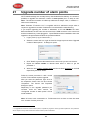
Upgrade number of alarm points _____________________________________ 89
22
Restart ___________________________________________________________ 90
23
Access ___________________________________________________________ 94
24
Perform monthly test (H1) ___________________________________________ 96
25
Disable or re-enable (H2) ____________________________________________ 99
25.1
Zone or zone address (H2/B1) ----------------------------------------------------------------- 100
25.2
Output (H2/B2) ------------------------------------------------------------------------------------- 102
25.3
Output type (H2/B3) ------------------------------------------------------------------------------- 104
25.4
Alarm devices (H2/B4)---------------------------------------------------------------------------- 106
25.5
Routing equipment (H2/B5) --------------------------------------------------------------------- 108
25.6
Alert Annunciation (H2/B6) ---------------------------------------------------------------------- 110
26
Set calendar and clock (H3) ________________________________________ 112
27
Present system status (H4) _________________________________________ 113
27.1
Disablement (H4/U1)------------------------------------------------------------------------------ 113
27.2
Disablement by time channel (H4/U2) -------------------------------------------------------- 114
27.3
Open doors (H4/U3) ------------------------------------------------------------------------------- 115
27.4
Sensor values (H4/U4) --------------------------------------------------------------------------- 116
27.4.1
Performance factor:.......................................................................................... 117
27.4.2
Algorithms ........................................................................................................ 118
27.5
Sensors activating SERVICE signal (H4/U5) ----------------------------------------------- 119
27.6
Technical warning (H4/U6) ---------------------------------------------------------------------- 120
27.7
Event log (H4/U6) ---------------------------------------------------------------------------------- 121
27.8
Information (H4/U8) ------------------------------------------------------------------------------- 122
28
Service (H5) ______________________________________________________ 123
28.1
Calibration of supervised outputs (H5/A1) --------------------------------------------------- 124
28.2
Sensitive fault detection mode (H5/A2)------------------------------------------------------- 125
4
Operation Manual
FT1020G3 Rev 2.0
28.3
Service mode for COM-loop (H5/A3)---------------------------------------------------------- 126
28.4
Display current consumption in unit (H5/A4) ------------------------------------------------ 127
28.5
Display current consumption COM-loop (H5/A5) ------------------------------------------ 128
28.6
Display statistics for communication (H5/A6) ----------------------------------------------- 129
28.7
Activate address setting mode for DU (H5/A7) --------------------------------------------- 130
28.8
SSD information (H5/A8) ------------------------------------------------------------------------- 131
29
FAULT Acknowledge (H6) __________________________________________ 132
30
Perform ZONE TEST (Test mode) (H7) ________________________________ 134
31
Maintenance (H8) _________________________________________________ 137
31.1
Password for service / maintenance ---------------------------------------------------------- 137
31.2
Disconnect / Reconnect loop / zone line input (H8/S1) ----------------------------------- 137
31.3
Acknowledge SERVICE signal (H8/S2) ------------------------------------------------------ 139
31.4
Clear weekly average (H8/S3) ------------------------------------------------------------------ 141
31.5
Test of alarm devices (H8/S4) ------------------------------------------------------------------ 142
31.6
Safe shut down of control unit (H8/S5) ------------------------------------------------------- 143
31.7
Activate address in alarm mode (H8/S6)----------------------------------------------------- 145
31.8
Synchronise the control units (H8/S7) -------------------------------------------------------- 146
31.9
Activate / Reset outputs (H8/S8) --------------------------------------------------------------- 148
32
Interlocking outputs and inputs (H9) _________________________________ 150
32.1
Activated interlocking outputs / inputs (H9/C1) --------------------------------------------- 150
32.2
Activate / deactivate interlocking output (H9/C2)------------------------------------------- 151
32.3
Disable / re-enable interlocking output (H9/C3) -------------------------------------------- 153
32.4
Change password (H10) ------------------------------------------------------------------------- 155
33
Maintenance _____________________________________________________ 156
33.1
How to change paper in the printer ------------------------------------------------------------ 156
33.2
Replacing a TLON connection board and/or the Main board --------------------------- 157
33.3
Battery maintenance ------------------------------------------------------------------------------ 157
34
How to avoid nuisance fire alarms ___________________________________ 158
35
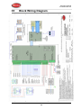
Block Wiring Diagram _____________________________________________ 160
36
Guarantee _______________________________________________________ 161
37
Revision history __________________________________________________ 162
5
Operation Manual
FT1020G3 Rev 2.0
Table of Figures
Figure 1 FT1020G3 Control Unit with printer and options ..................................... 16
Figure 2 FT1020G3 with front and display............................................................ 17
Figure 3 Occupant Warning System display......................................................... 22
Figure 4 Gas Extinguishing Display Layout .......................................................... 25
Figure 5 Assembled Control & Interface Boards................................................... 26
Figure 6 1668 Fire fan control .............................................................................. 27
Figure 7 Zone disable and indications.................................................................. 28
List of Tables
Table 1 Control unit specifications ....................................................................... 14
Table 2 Control unit limitation .............................................................................. 15
Table 3 LED indicators on Fire Brigade Panel (FBP)............................................ 18
Table 4 Push buttons on Fire Brigade Panel (FBP) .............................................. 19
Table 5 LED indicator on Control Panel (CP) ....................................................... 20
Table 6 Push buttons / keypad on Control Panel (CP).......................................... 21
Table 7 OWS controls and indications ................................................................. 23
Table 8 Gas Front Status LED Indication and flash Pattern .................................. 25
Table 9 Indicators and buttons in 1668 module .................................................... 27
Table 10 Zone control LEDs and Buttons............................................................. 28
Table 11 Symbol indications ................................................................................ 30
Table 12: Priority Order ....................................................................................... 30
Table 13: Access Levels and user names ............................................................ 32
Table 14 Data affected by restart ......................................................................... 91
Table 15 Algorithms and abbreviations in normal mode ..................................... 118
Table 16 Algorithms for 4400 in advanced mode ............................................... 118
Table 17 Algorithms for 4401 in advanced mode ............................................... 118
6
Operation Manual
FT1020G3 Rev 2.0
1
Introduction
1.1
Overview
FT1020G3 Operation Manual is a document intended to be used by the end-user and
the fire brigade personnel as well as service / commissioning engineers.
Due to continual development and improvement, different S/W versions are to be
found. This document is valid for software (firmware) version 2.0.x. On the date / rev
date of this document x = 0.
The software version is the firmware downloaded in to the control unit via PC windows
based software. The latest software is factory downloaded in the control unit before
delivery however, new software may be upgraded to a new revision on site.
The software version is dependent on the country where the control panel to be
installed, that is due to the variations in the standard in each country. Two separate
software versions are available, Australian (AU) and New Zealand (NZ).
The PC software is a windows based software to be installed in your PC, it’s called
EBLWin and must have a version number similar to the software (firmeware) version
number i.e. version 2.0.x. The EBLWin is used to download the firmware and the Site
Specific Data (SSD) into the control unit.
Only the first two digits must be the same in the software and the EBLWin version
number i.e. 2.0.x (x = minor modifications).
1.2
Definitions
Definitions and abbreviations are used frequently in this document and shown in the
following sections.
1.2.1
Alarm points
Units, which can generate a fire alarm (in the control unit), i.e. analogue detectors
(sensors), conventional detectors, manual call points, COM loop modules, etc.
1.2.2
Smoke detector
Analogue and conventional photoelectric (optical) smoke detectors are available.
Sensor
1.2.3
Analogue detector (sensors)
Contains an A/D - converter. The Control Unit picks up the digital values ("sensor
values") for each detector individually. All evaluations and "decisions" are then made
in the C.I.E. Analogue detectors are addressable, an address setting tool 4314 / 4414
is used to set up the addresses.
An analogue detector has to be plugged in an analogue sensor base (ASB).
7
Operation Manual
FT1020G3 Rev 2.0
1.2.4
Analogue detector (Sensor) Base (ASB)
A sensor is plugged in an ASB, which is connected to a COM loop (see below).
1.2.5
Conventional detector
Detector with only two status, either normal or fire alarm. A conventional detector in
alarm simulates low resistance (560 Ohm) across the zone line input. Normally
plugged in a conventional detector base CDB (see below) connected to a
conventional zone line input, with an end-of-line device. Some types are connected
directly on zone line.
1.2.6
Conventional Detector Base (CDB)
A conventional detector is plugged in a CDB, connected to a conventional zone line
input.
1.2.7
Addressable
A unit with a built-in address device, i.e. each unit is individually identified, handled
and indicated in the C.I.E.
(The unit can be an I/O unit with a zone line input, to which one or more conventional
"alarm points" can be connected.)
1.2.8
Conventional zone line input / Detector circuit
Input intended for one or more conventional alarm points. End-of-line device in the last
alarm point must be fitted.
1.2.9
Output unit
Addressable unit with programmable control outputs connected to a COM loop (see
below).
1.2.10
Output / Control output
Defined or programmable function, relay clean contact output or voltage output
(supervised / monitored) in the C.I.E. or an output unit connected to a COM loop.
1.2.11
Short circuit isolator (ISO)
Addressable unit for automatic disconnection of a part (segment) of a COM loop (see
below) in case of a short circuit on the loop. One isolator is required per 40 devises on
the COM loop.
1.2.12
Remote Display Unit (RDU)
The RDU is an addressable unit for fire alarm presentation (including user definable
text messages, if programmed). Two types are normally used: Alarm presentation unit
(APU) and alert annunciation unit (AAU)
8
Operation Manual
FT1020G3 Rev 2.0
1.2.13
COM loop
Loop = twisted pair cable, to which all the addressable units can be connected. Starts
in the C.I.E. and it returns back to the C.I.E.
1.2.14
Control Unit / C.U. / C.I.E.
Control Unit = Control and Indicating Equipment = Unit to which the alarm points are
connected (via a COM loop). Indicates on the front fire alarms, fault conditions, etc. A
printer can also be included in the control unit.
1.2.15
Fire Brigade Panel (FBP)
The fire brigade panel is an integral part of the control unit intended for fire alarm, fault
and disablement presentation, etc. The FBP compromises the top part of the front
display.
1.2.16
Control panel (CP)
A part of the control unit intended for the building occupier, service personnel, etc., to
"communicate" with the control unit / system. It compromises the bottom part of the
front display.
1.2.17
System
One or more control units connected via a TLON network (co-operating control units).
1.2.18
LED
LED (Light Emitting Diode) = Yellow, green or red optical indicator ("lamp").
1.2.19
External Indicator LED (RIL)
A unit with an LED, connected to an ASB, CDB or a detector with an output for an
external LED.
Illuminates when the built-in LED in the detector is lit.
1.2.20
Display / LCD
LCD (Liquid Crystal Display) = Display (in the C.I.E. or Display unit) for presentation of
fire alarms, fault messages, etc. In FT1020G3 it is a graphical monochrome LCD (320
x 240 dots) with backlight.
1.2.21
Door open
In FT1020G3 there is a door switch, which is activated when the control unit door is
open.
When the door is open a message "Door is open in this unit" is shown in the LCD.
9
Operation Manual
FT1020G3 Rev 2.0
1.2.22
Site Specific Data (SSD)
The SSD is unique for each installation. All alarm points, presentation numbers, user
definable text messages, programmable outputs, etc. are created in the PC program
EBL Win and also downloaded in FT1020G3 unit(s) with EBL Win.
1.2.23
Software (S/W) / System program
The software (S/W) – also called Firmware and system program - makes the control
unit (the microprocessor) work. It is factory downloaded but a new version can, via
program EBL Win be downloaded in FT1020G3 on site.
1.2.24
Network / TLON® / LonWorks® / Echelon / Node / TLON
Conn. board / Gateway / Sub net / Backbone net / Router /
Repeater
Brief explanations to the words / expressions may be found in the relevant documents.
See also separate TLON Technical description.
TLON® = TeleLarm Local Operating Network = a LonWorks®- based network for
communication between several units / nodes. The protocol is LonTalk and the
transmission works with doubly-terminated bus topology (Echelon FTT-10). To
connect a control unit to the network, a TLON connection board 5090 has to be
plugged in the control unit. FT1020G3 also supports redundant TLON system
communication. In this case two TLON connection boards have to be plugged in each
control unit.
A network can be one channel (FTT-10) or several channels, connected via routers.
(In the TLON Network a sub net = a channel.)
Routers are also used to increase the maximum cable length, node to node, in a
network.
Router or Repeater is the same type of unit with different configuration to select either
as a router or repeater.
Note: routers are not required in a redundant TLON network however it can only be
used to increase the network cable length between two nodes.
Fibre optic routers are available to interface the TLON networking between control
units via fibre optic cables. The type of fibre optic router is dependent on the cable
type e.g. single or multi mode, distance between any two nodes, etc. Care must be
taken when selecting the router type. Brooks recommends Westermo LRW-112 series
of fibre optic routers.
The PC program "TLON Manager" (V2 or V1.2) must be used to configure the TLON
network and create the number of control units in a system.
Note: The TLON configuration must be performed prior creating the site specific data
(SSD).
10
Operation Manual
FT1020G3 Rev 2.0
2
Overview
2.1
The FT1020G3 system
FT1020G3 is a microprocessor controlled intelligent fire alarm system, intended for
analogue addressable smoke detectors, as well as conventional detectors and manual
call points. Programmable control outputs and output units are available. Up to 1020
addresses can be connected to each control unit (C.I.E.).
FT1020G3 is available in several types, versions and configurations. It can be
connected to a TLON network, i.e. in a "system", with up to 30 control units. Each
control unit has access to all information.
FT1020G3 is designed and assessed to the Australian Standard AS7240.2, AS7240.4
and NZS4512:2010. The Fire Brigade Panel controls are incorporated as part of the
front fascia and conform to AS4438.3 - 2010.
2.1.1
Printer
The control unit FT1020G3 can be fitted with an optional printer.
2.1.2
Expansion boards
In the control unit (C.I.E.) it is possible to mount up to six expansion boards. The
following types are available:
Product type no.
Product name
4580
8 zones expansion board
4581
8 relay outputs expansion board
4583
Inputs and outputs expansion board
For more information, see also the FT1020G3 Technical Manual and drawings.
2.1.3
Power supply
The primary power source is a switch mode power supply, 230V AC / 24V DC, 6.5 A
150 Watt).
The secondary power source is a backup battery (2 x 12V). In the standard enclosure,
up to 17 Ah batteries can be fitted. Larger batteries (up to 65 Ah) requires additional
battery box.
The batteries and the DC output of the switch mode power supply are connected to
the Main board (5010) as shown in the block wiring diagram dwg. No. F725. The
power supply and battery capacity must be sufficient to run the system as required by
AS1670.2. See the FT1020G3 Technical Manual, chapter "Power supply" for more
information.
2.2
S/W versions
Due to continual development and improvement, different S/W versions may be found.
The same S/W version is required in all control units in a TLON Network. When
installing a new control unit in a system with "older S/W" control units, you must
11
Operation Manual
FT1020G3 Rev 2.0
upgrade the S/W in the old control units with the current S/W or downgrade the new
control panel software by downloading the same older S/W version in the new control
unit.
2.3
Documents
The following documents are available:
•
User Manual
•
Operation manual (this document)
•
Technical manual (planning instructions) 1
•
Block wiring diagrams
•
Commissioning test document
Normally information found in one document may not be found in another document,
i.e. the documents complement each other.
For TLON Network / TLON Manager, Web server, etc, separate documents are
available.
2.4
Applications
The FT1020G3 system is intended for small, medium and large installations. The
intelligent control units offer the system designer and end user a technically
sophisticated range of facilities and functions. Programming (PC programs EBLWin,
TLON Manager and EBL Web) and commissioning of the control unit / system is an
easy process. Start with one control unit and then, when required, add more units.
The TLON network allows the installer to install the control units in one building or in
different buildings.
2.5
PC programs
The following PC programs are used together with the FT1020G3 system.
2.5.1
EBLWin
The PC program EBLWin is used for programming and commissioning of one or more
control units i.e. to:
•
Auto-generate, i.e. to identify the units connected on a COM loop and create
default settings, which can be edited, saved and used as a site specific data
(SSD).
•
Create and download / backup (upload) of site specific data (SSD)
•
Download new software (firmware), settings, conventions, configurations,
control unit & system properties, etc.
•
Create / download the user definable text messages (alarm texts) shown in
the display in the C.U. and Display units.
•
See alarms, faults, disablements and acknowledge or reset them.
EBLWin must have the same version number as the EBL512G3 S/W version number
e.g. 2.0.x and 2.0.x respectively (x indicates only a small correction and is not required
1
On the date of printing this manual, the help tap in EBLWin contains the Panasonic planning instructions.
12
Operation Manual
FT1020G3 Rev 2.0
to be the same). Old SSD files can be opened in a newer (higher) version of EBLWin,
then edited, saved and thereafter downloaded to FT1020G3 control units with the
corresponding version.
2.5.2
TLON Manager
The PC program TLON Manager is used for the TLON Network programming,
installation, etc. (TLON Manager 1.2 and TLON Manager 2.0 can be used.)
2.5.3
EBLWeb Config tool
The PC program EBLWeb Config tool is used for configuration of the Web-server II
(1598)
13
Operation Manual
FT1020G3 Rev 2.0
3
Control Unit
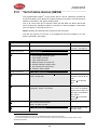
3.1
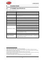
FT1020G3 Specifications
Table 1 Control unit specifications
Item
Specifications
Mains Voltage
230V AC (176-264), 1.6A
System Voltage
24V DC
Current Consumption
Depends on no. of expansion board, external equipment, type of
2
loop devices, etc. .
Ambient Temperature (⁰C)
Operating 0 to + 40, Storage -40 to +70
Ambient humidity (%RH)
Maximum 90, non-condensing
Size (mm)
Standard cabinet 920H x 450W x 210D (with metal door closed) 3
Enclosure Material
1.5 Zinc anneal steel
Enclosure Colour
Oyster, ripple finish
Approvals
AS7240.2, AS7240.4 and AS4428.3:2010
Four COM loops (0-3), each loop can connect up to 255 devices
Four programmable Supervised voltage outputs, 1 Amp each
Two programmable relay outputs, contact rating 2 Amp
Standard Inputs / Outputs
4
Four programmable clean contact (N/O or N/C) inputs (I0-I3)5
Two non-programmable relay outputs for ASE (fire & fault)
Six x 24V outputs for Web server, ASE, remote display units,
external applications 2-4 Amp.
Expansion Boards
Max. 6 of 4580, 4581 or 4583 (only 2 x 4583 allowed) 6
I/O Matrix 4582 board
7
Max. 24, 6 per COM loop if no expansion boards on Loop 0 fitted.
Up to 6 modules can be used as zone or generic + 18 Fan control
modules (4 fans per module)8
2
Refer to the technical manual and the current calculation spread sheet.
Medium size enclosure 630H x 450W x 210D can be used if the options are very limited. A combination of large and
medium enclosures can be used to fit more options. In 19” rack cabinets, a series of different face plates are also available.
4
Refer to G3 block wiring diagram, drawing no. F765
5
First input I0 cannot be used in NZ convention, only 3 programmable inputs are available.
6
Expansion boards are internally connected to COM loop 0, ensure total number of expansion boards and I/O matrix boards
connected to COM loop 0 does not exceed 6.
7
Reduce the number of 4582 connected to COM loop 0 by one for every expansion board used.
8
If no expansion boards fitted, up to 24 fan control modules can be used i.e. 96 individual fans
3
14
Operation Manual
FT1020G3 Rev 2.0
3.2
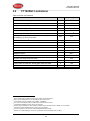
FT1020G3 Limitations
Table 2 Control unit limitations
Item
C.I.E.
General fire alarm via programmable input
Network System
100
External fault via programable input
50
Programmable outputs (= control expressions)
9
30 x 50
512
Technical warnings
50
Addressable 2 voltage outputs unit 3364
40
Interlocking Combinations
400
4000 10
Presentation numbers / alarm points11 that can be presented in
the display(s) in case of fire alarm
512
512
Presentation numbers8 that can be programmed
512
30 x 512 = 15 360
Zones that can be programmed
512
30 x 50
12
999
Faults
300
Disabled zones
512
Disabled alarm points (zone/address) + Disabled COM loops
200 13
Disabled outputs
200 14
Disabled interlocking outputs
200 15
Sensors activating SERVICE signal
AAF zones (Max. 5 detectors per AAF zone.)
200
16
100
Total number of expansion boards 4580, 4581 and 4583
Number of I/O matrix boards 4582
17
9
6
180
24
720
Approx. 4000 trigger conditions can be used in these control expressions.
Max. 100 user definable texts can be displayed "at the same time".
11
Presentation number is a ZONE only or ZONE – ADDRESS.
12
Any zone number between 001 and 999 can be used for the 512 zones.
13
Zone/address disabled via time channel not included.
14
Control outputs disabled via menu H2/B2 and Alarm devices disabled via menu H2/B4 are not included.
15
Interlocking outputs disabled via menu H9/C1 are not included.
16
Used in conjunction with the Alarm Acknowledgement Module (AAM).
17
Reduce no. of 4582 boards by one for every expansion board used (4580, 4581 or 4583).
10
15
Operation Manual
FT1020G3 Rev 2.0
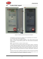
3.3
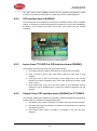
Control Unit Layout
Figure 1 FT1020G3 Control Unit with printer and options
The appearance and functions of FT1020G3 may vary depending on the convention
e.g. AU or NZ and the number of fitted options.
Figure 1 above shows the standard FT1020G3 in large cabinet fitted with some
options e.g. printer, Occupant Warning System, zone control module and AS1668 fan
control module.
NOTE: Special hardware is required to add the options.
The FT1020G3 control and indicating equipment (CIE) shown in Figure 1 is housed in
a powder coated metal cabinet, colour is oyster. The cabinet has an inner and outer
door. The outer door is fitted with a 003 key to provide access level 1 and is made of
tinted high impact plastic and allows easy viewing of all indicators and controls. The
look of the control unit might vary based on the number of fitted options, cabinet size,
etc.
Access to the inner door is gained by opening the outer door which then provides
access to the inner door fixing screws. Opening the inner door allows access to the
control unit hardware for the purpose of maintenance or servicing.
16
Operation Manual
FT1020G3 Rev 2.0
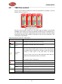
Figure 2 FT1020G3 with front and display
The fire brigade or fire services personnel use the integrated FBP to see which alarm
point / zone(s) have activated a fire alarm and take the required operational control of
the system. Fire brigade personnel can control active alarms via the buttons and keys
P1-P9 within the FBP. In the graphical display, the information displayed in the upper
part is dependent on how many alarm points / zones having generated a fire alarm. In
the middle part, the fire alarms will be shown, i.e. one alarm point or one zone
together with a user definable alarm text (if programmed) plus some other information.
The CP is used to "communicate" with the system, i.e. for commissioning, monthly
tests, maintenance, etc. Access codes for different access levels are required. To get
access to the system (a menu tree with main and sub menus) and for operational
control of the system, up to ten User names can be used for three different User level
18
types. A Password (six digits) for each User name is required.
3.4
LED indicators and push buttons
LEDs and push buttons can vary according to type and configuration (convention /
country).
See also Figure 2.
18
The same User names and Passwords (for the different user levels) will be used for logon to the Web-server.
17
Operation Manual
FT1020G3 Rev 2.0
Table 3 LED indicators on Fire Brigade Panel (FBP)
LED indicator
Indicating
L1
FIRE (5 red)
Fire alarms (see below)
Quiet alarm
See also chapter "Alarm types", page 47.
L2
FIRE PROTECTION
ACTIVATED (red)
Output(s) for extinguishing (suppression) equipment activated.
(Or a programmable input type "Extinguishing" is activated.)
L3
SMOKE CONTROL
ACTIVATED (yellow)
Output(s) for fire / smoke ventilation equipment activated (fire
fan). Or a programmable input type "Ventilation" is activated.
L4
ALARM ROUTING
ACTIVATED (red)
Output "Fire alarm" for fire brigade TX (routing equipment)
and/or corresponding programmable output(s) of type "Routing
equipment") is/are activated (or a programmable input type
"Activated routing equipment" is activated.)
Test of routing equipment in progress (see menu H1).
L5
L6
POWER (green)
SEVERAL ALARMS
(2 red)
The C.I.E. is powered via the primary power supply and/or the
battery.
More than one unit / zone have activated fire alarm. Use push
button "SEVERAL ALARMS" (P9) to scroll amongst the alarm
points (zone-address) or soft key "Next zone" (P6) to scroll
amongst the zones.
Different types of Fire alarms as follow:
•
Fire alarm (including test mode alarm)
•
Heavy smoke/heat alarm
•
Alert Annunciation (AA) alarm
•
Acknowledged alarm (New Zealand only)
•
Isolated alarm (New Zealand only)
18
Operation Manual
FT1020G3 Rev 2.0
Table 4 Push buttons on Fire Brigade Panel (FBP)
Push button
P1
P2
Operation/function
SILENCE BUZZER
(white)
Used to silence the buzzer in the C.I.E. when it is sounding
SILENCE ALARM
(red)
Used to silence alarm devices e.g. OWS / sounders 19 in the
building when they sound. Silenced Alarm devices is
indicated to the right in the display's soft key area (a symbol
near this button), see page 29
Used to reset:
• Fire alarms (see below)
P3
RESET (green)
• Co-incidence alarms (if not automatically reset), for
more information see "Fire alarm reset", page 58.
NOTE! P3 has to be pressed for > 0.5 sec.
P4
P5 - P8
P9
DISABLE (yellow)
Used to disable active alarm(s), all outputs of the device or
zone in alarm will be disabled.
Soft keys (grey)
The operation/function is shown above the key in the display
(i.e. the soft key area). The function of a soft key may vary
depending on the situation. If nothing is shown above the key
in the display, the key has no function at this moment 20.
SEVERAL ALARMS
(grey)
Used when LEDs "SEVERAL ALARMS" (L6) are lit to scroll /
browse through the several alarm points (zone-address). For
more details, see chapter "Fire alarm" page 48, under LEDs
"SEVERAL ALARMS".
NOTE! To scroll/browse through the queued zones, use the
soft key "Next zone" (P5).
Different types of Fire alarms as follow:
•
Fire alarm (including test mode alarm)
•
Heavy smoke/heat alarm
•
Alert Annunciation (AA) alarm
•
Acknowledged alarm (New Zealand only)
•
Isolated alarm (New Zealand only)
Encapsulated reset (auto disablement): Press "RESET" (P3) and approx. 0.1 sec.
later also press "SEVERAL ALARMS" (P9). See also page 59. This function must not
be used in the Australian convention.
Multiple reset (when single reset is selected), press “RESET” (P3) and approx.. 0.1
sec. later, press also "↲" (Enter).
19
20
Outputs of type "Alarm devices" will be de-activated.
The soft key “P8” has the function Alert Annunciation Acknowledge.
19
Operation Manual
FT1020G3 Rev 2.0
Table 5 LED indicator on Control Panel (CP)
LED indicator
L7
L8
System fault (yellow)
Test mode (yellow)
Indicating
FT1020G3 is not running because of S/W, CPU or memory
fault, no contact between main board and MMI board or
C.I.E. restart (fault code ≠ 00 / 03).
One or more zones are in "test mode", see page 96 and 134.
Fault / Disablements
L9
General fault (yellow)
Fault(s) in the system, i.e. not acknowledged fault(s) and/or
not corrected fault(s). See also page 132.
L10
General disablements
(yellow)
Disablement(s) in the system. Also valid for "Single reset with
automatic disablement", see page 59.
Alarm devices (yellow)
Steady: Output(s) type "Alarm devices" is disabled.
Blinking: One or more supervised outputs type "Alarm
devices" have generated fault(s).
This is also valid when the C.I.E. has no "contact" with a unit
with such an output, e.g. 3377, 3379, 3364, etc.
Fire brigade TX
(yellow)
Steady: Output(s) for "Routing equipment" disabled via
menu (H2/B5) or via open door.
21
Blinking: Routing equipment power supply output or one
or more supervised outputs (of type "Routing equipment"
have generated fault(s). This is also valid when the C.I.E.
has no "contact" with a unit with such an output, e.g. 3361,
etc.
L11
L12
Routing equipment
L13
Fault TX activated
(yellow)
22
One or more not acknowledged faults . Output "Fault
condition" for fault TX (routing equipment) is activated.
Test of routing equipment in progress (see menu H1).
Sensitive fault detection mode (see menu H5/A2) is on.
L14
Fire brigade TX delay
(yellow)
The Alert Annunciation function is enabled, i.e. time channel
controlling this function is "on". The AA function is described
in the FT1020G3 Technical Manual, chapter "Alert
Annunciation". LED "L14" will be "on" if the AA function is
enabled for at least one alarm point / zone. Normally one
only time channel is used for this function but two or more
channels can also be used. As an alternative, the AA
function can be continuously "on".
Note: Acknowledged alarm and isolated alarm are used only in the NZ convention.
21
Main board 5010 term. block "J3:3-4", fuse F8 (T500mA L 250 V – TR5).
22
See also chapter “Fault acknowledge”, Page 77
20
Operation Manual
FT1020G3 Rev 2.0
Table 6 Push buttons / keypad on Control Panel (CP)
Key/push button
Operation/function
(Enter)
Used to log on, i.e. to get access to the menu tree (via an
access code) and to accept a menu and accept input of data.
Also used by fault signal and service signal to acknowledge
the selected fault / analogue smoke detector.
◄►▲▼
Left / right keys are used to move the cursor in a menu.
Up / down keys are used to scroll between the menus.
1 – 9 and 0
Numeric key pad for the digits 0-9. Can be used to input data
and in the menu system to jump to a menu with a
corresponding number (e.g. 5 for a jump to menu H5).
DEL
Used to clear /delete all visible entry fields.
ESC
Used to stop input of data or to step "one step up" in the
menu system (e.g. from a sub menu to the main menu).
NOTE: The soft key "Escape menu" (P5) is used to leave the
menu system.
21
Operation Manual
FT1020G3 Rev 2.0
4
Control Unit Options
4.1
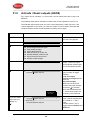
Occupant Warning System (OWS)
The standard Brooks OWS display and control layout is shown in Figure 3. For more
details, refer to the standalone OWS manual MA380 or OWS kit manual MA385.
OCCUPANT WARNING SYSTEM
Auto
Isolate
Fault
PA Mic
Alert
Man
Evac
PA
Press
To Talk
Figure 3 Occupant Warning System display
Brooks occupant warning system is a single zone system designed to warn the
occupant to evacuate the building in the event of fire or emergency.
The OWS comprises of amplifier, control / indication front and speakers / strobes
distributed within the building to provide audible and visual warning to the occupant as
well as PA notifications. In addition to the T3 and AS2220 tones, the OWS provides in
its standard configuration alert and evacuation messages as well as electret
microphone for PA purposes.
Brooks OWS can be incorporated in FT1020G3 system inside the same cabinet. It
provides high quality audio output utilising high efficiency class D amplifier, sizes
available: 60W, 120W and 250W.
Features:
•
Selectable time delay between alert tone / message and evacuation tone /
message.
•
Auxiliary input to connect to single or multiple zone remote microphone.
•
Supervised speaker circuit, trigger input and strobe output.
•
Optional up to 16 PA speaker zone controls. Each speaker zone is individually
monitored for short-circuit and open-circuit conditions
•
OWS fault changeover relay output to report a fault condition in the FT1020G3
•
Powered from the CIE power supply for 60W version, larger size amplifiers
require separate power supply and PSU supervision module.
•
Fault condition is generated when the OWS is left in isolate or manual mode
for more than 5 minutes.
22
Operation Manual
FT1020G3 Rev 2.0
Table 7 OWS controls and indications
LED indicators & Buttons
Auto
LED - Green
Illuminates to indicate the “Auto” position of the button,
normal position.
Button
OWS controlled only by alarm condition
LED - Yellow
Illuminates to indicate “Isolate” position of the button.
Button
Disable all outputs to the speakers, C.I.E. fault is generated if
the isolate button remains active for more than 5 minutes
LED – Red
Illuminates to indicate the “Manual” position
Button
Enables manual activation of Alert, Evac or PA. OWS fault is
generated if the manual button remains active for more than 5
min.
LED – Green
Indicates that alert tone/message is active
Button
Manual trigger of the alert tone/message
LED - Red
Indicates that evacuation tone/message is active
Button
Manual trigger of the evacuation tone/message
LED - Yellow
Indicates that PA is enabled
Button
Enables PA mode
LED - Yellow
Indicates PA is broadcasting
Button
Press and hold to broadcast via the electret mic
Yellow
Indicates common fault in OWS i.e. speaker fault, trigger
fault, strobe fault, etc.
Isolate
Manual
Alert
Evac
PA
Press to Talk
Fault
Indicating
23
Operation Manual
FT1020G3 Rev 2.0
4.2
Gaseous extinguishing system control module
4.2.1
Overview
The gaseous extinguishing system control module is provided for use as an option in
FT1020G3. The module is comprised of the following:
•
Control Board (SUB928), software is configured to interface with C.I.E.
•
Display Board (SUB929)
•
CIE interface board (SUB943).
•
Front panel decal with interconnection cable
In addition to the control module, system ancillaries will include:
•
A combination of Brooks Warning Signs
•
Brooks Local Control Station (LCS)
•
Voice / Tone Electronic Sounder
•
Dual Strobe Module
The control module combined with other Brooks system components has been
designed to provide the monitoring and control functions of a complete gaseous
extinguishing system that meets the requirements of the relevant clauses 7.1 to 7.6 of
the Australian Standard AS4214-2002 (including amendment 1). For more details,
refer to FT2GAS Operation / technical manual MA400.
The control module has the following inputs / outputs:
•
Fully supervised input circuits e.g. gas lock-off valve input, manual release
input and gas discharged sensor input.
•
Fully supervised system inoperative warning sign 24V output rated @ 0.5A
maximum.
•
Fully supervised 2 wire system output for level 1 and level 2 alarm to Brooks
warning signs (alarm 1 [+/-] & alarm 2 [-/+]) rated @ 3A maximum.
•
Fully supervised gas release output rated @ 5A maximum.
•
Gas release clean-contact relay output rated @ 2A maximum.
•
Gas Fault clean-contact relay output rated @ 2A maximum.
•
Gas Isolate clean-contact relay output rated @ 2A maximum.
•
One four-wire Local Control Station (LCS) interface. Both the local gas isolate
control and the local gas release control are fully supervised for open and
short circuit faults.
•
Adjustable gas release timer settings via a built-in DIP switch.
Note: the current rating above is the maximum current capacity of the outputs, a
power supply calculations must be performed to ensure that the power supply capacity
is sufficient to run the system in full alarm condition without exceeding the maximum
current rating of the power supply.
4.2.2
Display board (SUB929) & decal
The display board (SUB929) and decal layout is shown in Figure 4 on page 25.
All LED indicators on the front display are covered by a polycarbonate decal clearly
labeled with their functions.
When the system sets in the normal condition, all LED indicators will be extinguished.
24
Operation Manual
FT1020G3 Rev 2.0
Gas Extinguishing
1st Alarm
2nd Alarm -Timer Running
Gas Initiated
Gas Discharged
Gas Externally Released
Gas Discharge Inhibited
Gas Fault
Gas Disabled
Service
Master Abort
Figure 4 Gas Extinguishing Display Layout
The gaseous extinguishing system status indicating LEDs and flash patterns are
described in the following table. The default state of the LED indicators is OFF, if it is
not defined below.
Table 8 Gas Front Status LED Indication and flash Pattern
Type
LED Name
1st Alarm
2nd Alarm – Timer Running
Alarm
Gas Initiated
Gas Externally Released
Gas Discharged
Fault
Both zones or zone addresses in alarm
Gas release output activated
Fast
Flash
External gas release control activated
Gas discharged sensor input activated
Fault in any of the supervised inputs or
outputs
Gas Discharge Inhibited
Gas discharge inhibited via LCS isolate
switch
Disable
LED
Pattern
One zone or zone address in alarm
Gas Fault
Gas Discharge Disabled
4.2.3
Module Conditions
Gas discharge disabled by the service
master abort switch or the gas lock-off valve
controls
Service Switch Active
Illuminates when the master abort switch is
activated
Service, Master Abort
Gas service master abort switch
Steady
ON
Steady
ON
Control board (SUB928)
The control board (SUB928KT) is mounted on top of the CIE interface board
(SUB943), refer to Figure 5 on page 26
25
Operation Manual
FT1020G3 Rev 2.0
The gas control board SUB928 provides all the gaseous extinguishing control
functions. It provides the termination and supervision of all the field equipment.
4.2.4
CIE interface board (SUB943)
The CIE interface board (SUB943) is mounted at a suitable location inside FT1020G3
cabinet. It provides the required terminations to interface the control board SUB928 to
FT1020G3. This includes zone alarm, Zone fault, zone isolate and gas release
conditions.
Figure 5 Assembled Control & Interface Boards
4.2.5
Inputs from FT1020G3 to CIE interface board (SUB943)
The following inputs are provided in the gas interface board:
1. 24V supply (22-30V), 200mA to 3A based on system power calculation
2. Zone 1 & Zone 2 alarm, open clean alarm contact for each zone or zone
address
3. Fault input, zone 1 fault, zone 2 fault or power supply fault in the CIE will
activate the system inoperative sign. Fault input should be normally closed
clean contact.
4. Zone Isolate input, if any of the two zone inputs or zone addresses used to
release the gas is disabled (open contact), the system inoperative sign will
activate.
4.2.6
Outputs from CIE interface board (SUB943) to FT1020G3
The following outputs from SUB943 are provided to indicate the gaseous extinguishing
system status in FT102G3 via programmable inputs:
1. Gas isolate, relay output to indicate in FT1020G3 if the gas has been isolated.
2. Gas fault relay output to indicate in FT1020G3 if a fault exists in the gaseous
extinguishing system.
3. Gas release relay output to indicate in FT1020G3 if the gas has been
released.
26
Operation Manual
FT1020G3 Rev 2.0
4.3
1668 Fan control
The fan control module is designed to meet the requirements of AS1668.2. The front
display is shown in Figure 6.
F
Running
F
Running
F
Running
F
Running
A
Stopped
A
Stopped
A
Stopped
A
Stopped
N
Fault
N
Fault
N
Fault
N
Fault
On
On
On
On
Auto
Auto
Auto
Auto
Off
Off
Off
Off
Fan
Reset
1668 FAN CONTROL
LED
Test
Figure 6 1668 Fire fan control
Each fan control module consists of an I/O matrix 4582 and display / control board
(SUB902). Each module can control and indicate the status of up to 4 different fans. A
fan reset switch is provided to independently reset the fan module. A remotely located
(mechanical services) 3361 module is required for each fan and configured in the
control panel using EBLWin.
Table 9 Indicators and buttons in 1668 module
LED indicator & buttons
Indicating
Running
Fan running Red
Illuminates to indicate that the fan is running.
Stopped
Fan Stopped Green
Illuminates to indicate that the fan is stopped.
Fault
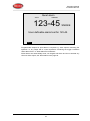
Fan Fault Yellow
Illuminates when the signal to the fan to change state is restored,
either via manual override switch or by the C.I.E in Auto mode but
the feedback signal confirming the change of state has not been
received by 3361 input in the field within 30 seconds.
Or
There is an open circuit in the 3361 supervised input where the
feedback from the pressure switch is connected.
Or
The pressure switch is playing up
On
Auto
Off
LED – Red
Indicates “On” position of the button, manual override start up
Button
Fan is running in manual mode independent of an alarm in C.I.E.
LED – Green
Indicates “Auto” position of the button, normal operation
Button
Fan may be running or stopped depending on the alarm condition
in the C.I.E
LED - Yellow
Indicates “Off” position of the button, manual override stop
Button
Fan is stopped in manual mode independent of an alarm in C.I.E.
27
Operation Manual
FT1020G3 Rev 2.0
4.4
Zone control module
The zone control module is used as a simple and easy method to disable individual
zones for service and maintenance purposes as well as providing alarm and fault
indication for these zones. The front display layout is shown in Figure 7
ZONE CONTROL
AL
Disable
Disable
DS
AL
Disable
AL
Disable
DS
FT
FT
FT
AL
AL
AL
DS
Disable
FT
DS
DS
Disable
FT
AL
Disable
DS
FT
DS
FT
AL
Disable
DS
DS
FT
AL
Disable
DS
FT
FT
AL
Disable
DS
AL
Disable
AL
Disable
FT
DS
FT
LED
Test
Figure 7 Zone disable and indications
Each zone control module consists of a universal I/O matrix 4582 and application
board SUB900 specifically configured to provide up to 12 individual zone alarm and
zone fault indicators as well as a disablement control with indicator to indicate switch
activation. The module is normally mounted in the C.I.E. but it is also possible to
connect the module externally via a COM loop.
The Zone Control Module provides a simplified indication of zone status without the
need for a liquid crystal display. The disable control allows a specific zone to be
temporarily disabled without the need to access the CIE menu. This is typically used
where building works or maintenance procedures are being carried out in a localised
area of a building.
Table 10 Zone control LEDs and Buttons
LED indicator & buttons
AL
Alarm – Red
1-12
DS
Disable - Yellow
1-12
FT
Fault – Yellow
1-12
Disable
Button
1-12
LED Test
Button
Indicating
Illuminates when an alarm from a conventional zone or an
addressable device or group of addressable devices designated
as a zone enters an alarm state.
Illuminates when a zone is disabled either by the disable switch
on the zone control card or where the zone is disabled via menu
H2/B1
Illuminates when either a short circuit or open circuit fault on
conventional zone or any fault that prevents an addressable
alarm point in a designated zone to operate properly.
Pressing the disable switch will disable the specific zone
selected. Pressing the switch a second time will re-enable the
zone. Functions same as menu H2/B1.
Is selectable to either be activated from the CIE or at the zone
control module itself, this feature can be utilised when the module
is mounted externally via the COM loop.
28
Operation Manual
FT1020G3 Rev 2.0
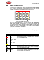
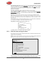
5
The display (LCD)
5.1
Areas in the display
Symbol area
Information area
Soft key area
Menu
Next zone
Re-enable
Alert annunc.
The display is divided into three areas:
•
The symbol area: Some events are indicated with symbols, see Table 11
below.
•
The information area: General area for all other information and the menu
system.
•
The soft key area: The functions of the soft keys are shown in the bottom
section of the display. The keys will vary depending on the situation and
convention. If no text is shown, the soft key has no function. The last soft key
is used to acknowledge an "Alert Annunciation” alarm. In the New Zealand
convention it is used to "Acknowledge Alarm".
Silenced Alarms is indicated by the symbol
to the right in this area.
29
Operation Manual
FT1020G3 Rev 2.0
5.2
Symbol area
The symbol area is located at the top of the display, see chapter 5.1 above.
Table 11 Symbol indications
Symbol area
Symbol
Indicating
The door is open in any C.I.E. See “Open doorpage” page 44. See also menu
H4/U3.
Loss of mains in any C.I.E. or external power supply unit in the system, i.e. blackout
or mains is switched off and the power is supplied via battery backup.
The week average sensor value has exceeded the service level for one or more
analogue smoke sensors in the system. See also page 119 and menu H4/U5.
The C.I.E. is set in “Sensitive fault detection mode” via menu H5/A2, see page 125.
One or more “Technical warnings” are generated in the system. See also menu
H4/U6.
Note that the symbol area may be suppressed see chapter Priority Order, Table 12.
5.3
The information area priority order
When the control unit / system is in normal operation (quiescent state), i.e. no fire
alarms, no faults, no disablements, no service signals, no zones in test mode, no
activated interlocking inputs/outputs, and/or Alert Annunciation function not enabled,
only the LED "Operation" (L5) should be lit and some system information is shown in
the control unit display. However, the system information has the lowest priority and
more important information suppresses less important. In some cases also valid for
the symbol area. The priority order is shown in Table 12.
Table 12: Priority Order
Priority
1
2
3
4
5
6
7
9
10
11
12
13
14
Event
Fire alarms (see below)
Quiet alarm
Co-incidence alarm
Delayed alarm
Pre-warning
Test mode alarm
AAF alarm
New Zealand convention only:
Routing equipment left isolated
Fault (not acknowledged)
Disablement
Zones in "Test mode"
Interlocking input / output active
System information
30
Symbol area
is visible
No
No
No
No
No
No
Yes
Yes
Yes
Yes
Yes
Yes
Yes
Operation Manual
FT1020G3 Rev 2.0
Different types of fire alarms as follow:
•
Fire alarm
•
Heavy smoke/heat alarm
•
Alert Annunciation (AA) alarm
•
Acknowledged alarm (New Zealand only)
•
Isolated alarm (New Zealand only)
The different type of events and the menu system are described in other parts of this
document. Regarding "System information in the LCD", see section “System
information in the LCD” below.
5.4
System information in the LCD
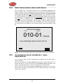
FT1020G3, control unit number, date and time are displayed.
An example:
FT1020G3
Control Unit: XX
dd-mm-yyyy hh:mm
dd-mm-yyyy = (Date) Day-month-Year
Control Unit; XX = 00-29
hh:mm = (Time) hour:minute
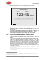
5.4.1
User definable system information
User definable system / installation information (created and downloaded via EBLWin)
can be displayed in the middle of the display. Two rows are available, 40 characters in
total. This information is shown in all control units in the system.
One example:
FT1020G3
Control Unit: XX
Brooks Australia
Main Office, 4 Pike St, NSW
15-02-2013 11:51
31
Operation Manual
FT1020G3 Rev 2.0
6
User level, User name & Password
FT1020G3 has different access levels for different users.
To log on to an FT1020G3 (version > 2.0) a User name and Password are required.
Ten different User names with individual Passwords can be used. Each User name
has a specific user level, which has access to specific menus according to Table 13.
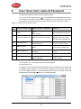
Table 13: Access Levels and user names
User
level
User level name / type Required action / equipment
0
None
Access to
None
(Door closed).
View indications and controls
1
Fire service personnel
Open door (003 key required).
Fire alarm response via fire
brigade section, fan control,
hot buttons zone disablement
2A
Information only
003 key + log on as
“Information only”
Same as 1 + keypad. Menu
H4, H6 a), H7, H9 b) & H10
2B
Building officer
003 key + log on as “Building
officer”
Same as 1 + keypad. Menu
H1-H4, H6, H7, H9 & H10
3A
Service personnel
003 key + log on as “Service
personnel”
Same as 1 + keypad. Menu
H1-H10
3B
-
PC + EBLWin + H/W key
SSD & S/W download
4
-
PC + EBLWin + H/W key +
special password
SSD & S/W download + reset
of alarm counter
a) Information only, i.e. the faults cannot be acknowledged.
b) Menu H9/C1 only.
Ten different User names with individual Passwords are available and can be defined
Via EBLWin (menu “System”) in the “User data” dialog box. They can be used to log
on to an FT1020G3 (version > 2.0) and/or Web-server access. Three User names and
Passwords are set as default as shown in the following table:
32
Operation Manual
FT1020G3 Rev 2.0
6.1
User level 0
With the door closed, no access, controls indicators are viewed through outer door.
6.2
User level 1
After the door has been opened using 003 key ("Door open"
symbol in
the symbol field), the designated user / fire brigade personnel have access to the
following push buttons:
Push button
Operation/function
P1
Silence the buzzer in the C.I.E.
P2
Silence all alarm devices (OWS or sounders).
P3
Reset fire alarms. (see below)
P4
Disable active alarm (S)
1668 Fan Control
Manual override of AS1668 fans, if fitted
Zone Disablement
Quick access to zone disablement, if fitted
Possible Fire alarms as follow:
6.3
•
Fire alarm (including heavy smoke/heat alarm)
•
Alert Annunciation (AA) alarm
•
Co-incidence alarm (if not reset automatically)
•
Acknowledged alarm (New Zealand only)
•
Isolated alarm (New Zealand only)
User level 2A
After the door has been opened with 003 key ("Door open" symbol
in
the
symbol area), you have access to level 2A and log on as “Information only” (level 2A),
access to the following menus:
H4 Present system status
U1 Disablement
U2 Disablement by time channel
U3 Open doors
U4 Sensor values
U5 Sensors activating SERVICE signal
U6 Technical warning
U7 Event log
U8 Information
H6 FAULT Acknowledge, NOTE: Information only
H9 Interlocking outputs and inputs
C1 Activated interlocking outputs / inputs
H10 Change password (In this case for “Information only”.)
33
Operation Manual
FT1020G3 Rev 2.0
6.4
User Level 2B
After the door has been opened using 003 key ("Door open" symbol
in the symbol
area), you have access to level 1 and after log on as “Building officer” (level 2B),
access to the following menus:
H1 Perform monthly test
H2 Disable or re-enable
B1 Zone or Zone / Address
B2 Output
B3 Output type
B4 Alarm devices
B5 Routing equipment
B6 Alert annunciation function
H3 Set calendar and clock
H4 Present system status
U1 Disablement
U2 Disablement by time channel
U3 Open doors
U4 Sensor values
U5 Sensors activating SERVICE signal
U6 Technical warning
U7 Event log
U8 Information
H6 FAULT Acknowledge
H7 Perform ZONE TEST ("Test mode")
H9 Interlocking outputs and inputs
C1 Activated interlocking outputs / inputs
C2 Activate / deactivate interlocking output
C3 Disable / re-enable interlocking output
H10 Change password (In this case for “Building officer”.)
34
Operation Manual
FT1020G3 Rev 2.0
6.5
User level 3A
After the door has been opened using 003 key ("Door open" symbol
in the symbol
field), the service / maintenance personnel have access to level 1 and after log on
as “Service personnel” (level 3A), access to all menus, i.e. same as level 2B and also
to the following menus:
Same menus as in access level 2B plus the following:
H5 Service
A1 Calibration of supervised outputs
A2 Sensitive fault detection mode
A3 Service mode for COM-loop
A4 Display current consumption in control unit
A5 Display current consumption on COM-loop
A6 Display statistics for communication
A7 Activate address setting mode for DU
A8 SSD information
H8 Maintenance
S1 Dis- / Re-connect loop / zone line input
S2 Acknowledge SERVICE signal
S3 Clear weekly average
S4 Test of alarm devices
S5 Safe shut down of control unit
S6 Activate address in alarm mode
S7 Synchronize the control units
S8 Activate / Reset outputs
H10 Change password (In this case for “Service personnel”.)
6.6
Access level 3B
Used by Service / maintenance / commissioning engineers when a PC (i.e. EBLWin)
is to be connected to FT1020G3 for backup (upload), download of site specific data
and/or download of software.
EBLWin require a hardware key.
6.7
Access level 4
Used by manufacturer or by personnel authorised by the manufacturer for reinitialisation (reset) of the alarm counter, change software configurations, on-line
status checking, etc. A special password is required.
35
Operation Manual
FT1020G3 Rev 2.0
7
Silence Alarm devices
In the control unit front (the FBP part) there is a push button "SILENCE ALARM" (P2).
When the alarm devices are activated (sounding) 23 and the push button "SILENCE
ALARM" is pressed, the following will happen:
•
The symbol
•
The activated outputs programmed for OWS or sounders (i.e. type "Alarm
devices", will be turned OFF (de-activated)24
is shown in the display, to the right of the "Soft key” area.
If the push button "SILENCE ALARM" is pressed again, the fire alarm devices will
automatically re-sound.
In case of a new alarm, the alarm devices will automatically re-sound.
In EBLWin, the option {Button silence alarm devices disables alarm devices} can be
selected. In this case, the button "SILENCE ALARM" (P2) will have the same function
as the menu “Alarm devices (H2/B4)” page 106. See also chapter "Disable / Reenable alarm devices", page 39.
Note 1: This option (Button Silence alarm devices disables alarm devices) must not
be used in the Australian convention as this is a violation to AS4428.3 : 2010.
Note 2: In the NZ convention, the function is already implemented in the firmware i.e.
there is no need to tick the check box.
The “FIRE” LEDs will indicate steady instead of blinking when alarm devices are
disabled.
23
24
e.g. during Fire alarm or Alert Annunciation alarm.
Including Addressable siren 3377, Addressable sounder base 3379, Addressable beacon 4380 and Occupant Warning
System (OWS).
36
Operation Manual
FT1020G3 Rev 2.0
7.1
SILENCE ALARM (inside switch)
NOTE! The functions in this chapter are used only in the New Zealand convention.
The button "SILENCE ALARM" (P2) operates slightly different in the NZ convention
and has the following function:
The button SILENCE ALARM (inside switch) toggles between two states.
•
Alarm devices disabled
When the button is presses, all programmable outputs of type "Alarm devices"
are disabled, i.e. silences sounders, OWS, strobes, etc. and prevents new
alarms from activating the warning devices.
•
Alarm devices not disabled
When the button is pressed again, all programmable outputs of type "Alarm
devices" will be enabled, i.e. any alarm can activate the warning devices.
If the “SILENCE ALARM” button is left in its disabled state when the CIE door is being
closed, the buzzer will beep continuously and the message "Silence switch left active"
will be shown in the display. This feature is required in NZS4512:2010 to ensure that
the door cannot be closed while the alarm devices are disabled. For priority order see
chapter “The information area priority order” page 30.
NOTE: The "SILENCE ALARM" button on the front display has no function if the
“Silence alarms” Bulgin key in the FT1020G3 cabinet or in the remote fire brigade
panel (see below) is turned to the “Silence Alarms” position.
7.2
New Zealand FB “Silence Alarms” Bulgin key
(outside switch)
The New Zealand FB “Silence Alarms” Bulgin key switch is connected to NZ
mimic application board (SUB927) via a programmable input in the IO matrix board
4582 with the trigger condition "NZ Silence switch".
The fire brigade Bulgin key switch can be in two states:
1. The Bulgin key switch is turned ON (i.e. from non-activated to activated
state).
a. All programmable outputs of type "Alarm devices" are disabled. The
"SILENCE ALARM” switch in FT1020G3 front display (see above) has
no function.
b. LEDs "Fire" (on FT1020G3 front display) changes from blinking to
steady. 25
c.
The CIE built-in buzzer is silenced.
d. A fault is generated 26
"FAULT: FB Silence switch active"
2. The Bulgin key switch is turned OFF (i.e. from activated to non-activated
state).
a. The fault "FAULT: FB Silence switch active" will be Serviced
25
26
27
This is valid also if the fire alarm is activated after the Bulgin key switch is turned ON (Silence Alarms position).
Since this fault is always latched, it has to be acknowledged via menu H6.
37
Operation Manual
FT1020G3 Rev 2.0
b. Any fire alarm “ALARM” and acknowledged alarm ”ACKNOWLEDGED”
will be automatically disabled (isolated), i.e. it must be re-enabled via
menu H2/B1 and is indicated by LED “General disablement” on the
C.I.E. front.
c.
Any fire alarm "ALARM" and acknowledged alarm "ACKNOWLEDGED"
will automatically change state to "Isolated alarm" (see below) and in
the fire alarm list (presented in the display) "ALARM" or
“ACKNOWLEDGED” will be replaced by "ISOLATED".
An example:
1234567890123456789012345678901234567890
1.
2.
First alarm: 002-03
Alarm number 1 (of 1)
ISOLATED alarm
Zone
3.
4.
5.
6.
7.
8.
9.
10.
11.
12.
13.
14.
27
Address
002-03
SMOKE
User definable alarm text for 002-03.
Menu
Since this fault is always latched, it has to be acknowledged via menu H6.
38
Operation Manual
FT1020G3 Rev 2.0
8
Disable / Re-enable alarm devices
28
Outputs programmed for sounders or OWS (i.e. type 3 "Alarm devices") can be
collectively disabled via menu H2/B4 for all control units. This is indicated by LED
Fault / Disablements "General disablements" (L10) and "Alarm devices" (L11), which
are steady ON.
In case of a fire, the sounders or OWS will remain disabled, i.e. the alarm devices will
not sound until they are re-enabled again via menu H2/B4.
NOTE:
Outputs of type "Alarm devices" cannot be individually disabled, not even via menu
H2/B2 “Disable or Re-enable Output”
See also chapters "Test of alarm devices” (H8/S4), page142. All outputs of type
"Alarm devices" for a specified or all control units, can be activated for an alarm device
test.
28
Including Addressable siren 3377, Addressable sounder base 3379, Addressable beacon 4380 and Occupant Warning
System (OWS).
39
Operation Manual
FT1020G3 Rev 2.0
9
"SILENCE BUZZER" button
The buzzer in the control unit will sound for:
•
Fire alarm 29 (0.4 / 0.4 sec.)
•
Co-incidence alarm (2-zone or 2-unit dependent fire alarm): When only one
zone or one zone / address (alarm point) is in alarm status (0.8 / 5 sec.)
•
Pre-warning (0.8 / 5 sec.)
•
Quiet alarm (0.8 / 5 sec.)
•
Fault (continuous)
•
Disablements and Faults (1 sec. directly after the door to the C.I.E. is closed.)
•
Activated interlocking input (0.8 / 0.8 sec.), if this option is selected via
EBLWin.
Pr ess "SILENCE BUZZER" (P1) t o silen ce t h e b u zzer .
In case of a new alarm (pre-warning, co-incidence alarm, etc.) or if the push button
"SILENCE BUZZER" is pressed again, the buzzer will automatically re-sound.
Silence buzzer by open door
In EBLWin the function "Silence Buzzer by Door Switch" can be selected. The buzzer
will then be disabled as long as the control unit door is open.
NOTE: In the New Zealand convention, if any of the outputs for routing equipment
("Fire brigade TX" and "Fault TX") has been disabled, the built-in buzzer will sound
continuously once the door is closed. The message "Routing equipment left isolated"
will be shown in the LCD. This information has higher priority than the normal fault
messages and disablements.
29
Incl. Heavy smoke/heat alarm, AA alarm, Key cabinet alarm and Acknowledged alarm (New Zealand only).
40
Operation Manual
FT1020G3 Rev 2.0
10
Disable or re-enable Output
All control outputs (except outputs of type “Alarm devices”) can be
individually disabled via menu H2/B2:
•
Loop unit xxxxxx output x
•
Control unit xx S0
•
Control unit xx R0
•
Control unit xx expansion board x output x
This is indicated by LED Fault / Disablements "General disablements" (L10).
They will remain disabled until they are re-enabled again via menu H2/B2.
See also chapter Output type (H2/B3), page 104
See also chapter “Activate / Reset outputs (H8/S8)”, page 148. An output can be
activated for an output test.
41
Operation Manual
FT1020G3 Rev 2.0
11
Disable / Re-enable Control, Ventilation,
Extinguishing and interlocking outputs
30
All control outputs programmed as type:
•
Control (general)
•
Extinguishing
•
Ventilation (fire ventilation)
•
Interlocking
All the above control outputs can be collectively disabled via menu H2/B3 for one,
several or all control units. This is indicated by LED Fault / Disablements "General
disablements" (L10). They will remain disabled until re-enabled again via menu H2/B3.
See also chapter “Activate / Reset outputs (H8/S8)”, page 148. An output can be
activated for an output test.
See also chapter “Activate / deactivate interlocking output (H9/C2)”, page 151. An
interlocking output can be activated for an output test.
30
Terminology of Extinguishing and Ventilation has been changed in the fire brigade panel standard AS4428.3 : 2010.
Extinguishing re-named to “FIRE PROTECTION ACTIVATED” and Ventilation to “SMOKE CONTROL ACTIVATED”.
42
Operation Manual
FT1020G3 Rev 2.0
12
“DISABLE” Button
The “DISABLE” push button is provided in the fire brigade part on the front display to
enable the fire brigade personnel to disable (isolate) an active alarm such as a zone of
addressable sensors, conventional zone or individual addressable device.
A single operation of the “DISABLE” button (P4) whilst there is an active alarm will
initiate the following:
•
Disablement of all zones in alarm and/or addressable devices in alarm.
•
Illuminate the “General Disablement” LED L10.
•
Disablement of all the outputs configured for zone(s) or device(s) in alarm.
The output indicators activated as a result of an alarm will not clear automatically after
disablement. A subsequent reset operation is required to restore the C.I.E to the
normal condition.
Note:
The disablement button will not function unless the “SILENCE ALARM” button
has been activated first as required by AS4428.3:2010 31.
31
This function is not required in NZ convention.
43
Operation Manual
FT1020G3 Rev 2.0
13
Open door
A standard 003 key is used to open the control unit door to get access to the front
membrane and other optional modules e.g. OWS, zone disable, AS1668 fan control,
etc.
If a door in the system (any control unit) is open, the following symbol is shown in the
display's symbol area:
See also chapter Open doors (H4/U3), page 115.
13.1
Outputs for routing equipment (Fire brigade Tx
and Fault Tx)
Via EBLWin the outputs for routing equipment can be disabled by the door switch32.
The following can be programmed (default settings shown):
None: Open door in a C.U. will not disable the output(s) for routing equipment
(Fire brigade TX and fault TX).
Any control unit door: Open door in any C.U. will disable the output(s) for
routing equipment (Fire brigade TX and fault TX) in all C.U:s.
Any door: Open door in any C.U. or any external FBP33 will disable the
output(s) for routing equipment (Fire brigade TX and fault TX) in all C.U:s.
Disabled outputs for routing equipment are indicated by the LEDs Fault /
Disablements "General disablements" (L10) and "Fire brigade TX" (L12) and listed in
menu H4/U1.
13.2
Silence buzzer by door switch
The built-in buzzer in the C.I.E. can be set Via EBLWin to be silenced when the
cabinet outer door is opened.
32
33
This function MUST NOT be used in Australia and New Zealand
External Fire Brigade Panels (FBP) are not used in the Australian and NZ markets.
44
Operation Manual
FT1020G3 Rev 2.0
14
Technical / Presentation number
14.1
Technical number for COM loop units
The technical number “NN N NNN” is used when programming all units connected to
the COM loops.
Technical number is also used to identify which unit has generated a fault.
001 - 255
Technical address on a COM loop.
Addresses don't have to be in sequence.
Connections on the COM loop don't have
to be in sequence.
The address for each unit is set with the
programming tool 3314 / 4414.
Control Unit (CU) address (number).
CU numbers don't have to be in sequence.
Connections to TLON network don't have to
be in sequence.
The address is set with TLON manager
software V2.0 or V1.2.
NOTES:
1. Maximum of 1020 34 COM loop (technical) addresses can be used for one control
unit. Any address can be used for alarm point i.e. detector.
2. A brand new detector is factory set to COM loop (technical) address 000. If a
detector is connected on the COM loop without setting up an address (001 – 255),
the detector LEDs will start blinking every second, indicating that the detector has
not been addressed.
34
Since (technical) address 000 cannot be used, the total number of addresses is 4 x 255 = 1020
45
Operation Manual
FT1020G3 Rev 2.0
14.2
Presentation number
For each fire alarm point / input / zone, a presentation number NNN-NN has to be
programmed.
The presentation number is shown in the C.I.E. display, alarm presentation unit 1728
and alert annunciation unit 1736 to identify the point / zone activating fire alarm. It is
also used to disable / re-enable fire alarm points / zones and as a trigger conditions in
the control expressions to activate programmable outputs.
Together with the presentation number, a user definable 40 characters text message
(alarm text) can be displayed (if programmed).
NNN
- NN
00 – 99
01 – 99 = The address within the
zone.
00 = Only the zone number will be
displayed, e.g. used for
conventional zone line inputs.
001 - 999
Zone number
46
Operation Manual
FT1020G3 Rev 2.0
15
Alarm types
In case of a fire, analogue detectors (sensors), conventional smoke and/or heat
detectors, manual call points and programmable inputs can activate fire alarm.
A fire alarm could be an Alert Annunciation alarm, i.e. the activation of the routing
equipment (fire brigade TX) is delayed during an acknowledgement and investigation
time.
AAF alarm (Alarm Acknowledgement Facility) is similar to the alert annunciation
function and normally used to control the brigade call alarms. If the AAF function is
used, during the acknowledgment and the investigation periods, there will be an
indication in the CIE display and the fire brigade TX will be delayed. The AAF function
requires an Alarm Acknowledgement Module (AAM 3340), a smoke detector (sensor)
4300/4400 or 4301/4401 and sounder base 3379.
The analogue detectors (sensor) can also activate two other types of "alarm", i.e. Prewarning and Heavy smoke alarm / Heavy heat alarm.
"Two unit dependent" addressable alarm points (normally smoke detectors only) and
"2-zone dependent" zones, can activate a Co-incidence alarm.
Quiet alarm is an another alarm type, it is auto resetting analogue smoke detector
(sensor) that can be used for fan control and other applications that require a nonlatching / non-brigade call alarm.
Acknowledged and Isolated alarm is a fire alarm function only used in New Zealand.
Regarding the different alarm types, etc., see the following chapters.
NOTE:
In the following chapters, all different alarm types are described.
The figures in this document show the essential information and may not look
exactly as shown in the display.
15.1
Pre-warning
Activation of Pre-warning is an option enabled via EBLWin for the control unit.
Note: Pre-warnings activated in any control unit in the system will always be
presented in all control units and all programmable outputs in the system (with trigger
condition pre-warning) will be activated (if not disabled).
The analogue detector generates a pre-warning at a lower alarm level than the fire
35
alarm level. Pre-warning can be used when an early warning and/or an early action
is required (e.g. a "soft" computer shut down). Normal alarm devices (output type
"Alarm devices"), routing equipment, etc. will not be activated.
In case of a pre-warning, the following happens:
•
•
The buzzer in the C.I.E. sounds 0.8 sec. each 5th sec. (0.8 / 5 sec.).
36
Outputs programmed for pre-warning are activated.
35
See FT1020G3 Technical Manual. Any programmable input can also be used to activate a pre-warning, e.g. for a High
Sensitivity Smoke Detector system.
36
Outputs programmed for General pre-warning and outputs programmed for the activated pre-warning(s).
47
Operation Manual
FT1020G3 Rev 2.0
•
In the C.I.E. display, a presentation number (zone/address) is shown (for the
first pre-warning).
• In the C.I.E. display, a user definable text message (= the alarm text for fire
alarm) is shown (if programmed).
Example; pre-warning zone 123, address 45 (within zone 123):
Pre-warning
Zone
Address
123-45
SMOKE
User definable alarm text for 123-45.
Menu
"SMOKE" after the presentation number is automatically added depending on the type
of alarm point (i.e. SMOKE, HEAT, MULTI or MCP).
NOTE: The text "Menu" (P5) is visible in the display, only if the door in the CU is open.
If more than one pre-warning is activated, the LEDs "SEVERAL ALARMS" (L6) are
blinking and the pre-warnings will be automatically scrolled (each five seconds).
Pre-warnings are automatically reset see chapter "Alarm reset", page 58.
15.2
Fire alarm
The FT1020G3 system can handle up to 15360 fire alarms but only 512 fire alarms
can be shown in the C.I.E. display. If more than 512 fire alarms are activated, no
additional fire alarms can be displayed until one or more of the first 512 fire alarms are
reset.
It is possible to have Selective alarm presentation, i.e. only fire alarms from selected
control units will be presented in the control unit, set in EBLWin for each control unit.
See also chapter "The information area priority order", page 30. The following
happens in case of a fire alarm:
•
•
•
•
37
38
The buzzer in the C.I.E. sounds 0.4 sec. each 0.4th sec. (0.4 / 0.4 sec.).
LEDs "Fire" (L1) are blinking (0.4 / 0.4 sec.).
Output for routing equipment (Fire brigade TX) and outputs type "Routing
37
equipment" are activated.
38
Outputs for fire alarm are activated.
In case of Selective alarm presentation only for the selected alarms.
Outputs programmed for General fire alarm and outputs programmed for the activated fire alarm(s).
48
Operation Manual
FT1020G3 Rev 2.0
•
In the C.I.E. display, a presentation number (zone/address) is shown (for the
first fire alarm).
• In the C.I.E. display, a user definable text message (alarm text) is shown (if
programmed).
• In the C.I.E. display, some additional information is also presented.
One alarm point activating fire alarm.
Example; fire alarm zone 002, address 03 (within zone 002):
First alarm: 002-03
Alarm number 1 (of 1)
Zone
Address
002-03
SMOKE
User definable alarm text for 002-03.
1 zone in alarm
Menu
The presentation number is automatically followed by: SMOKE, HEAT, MULTI or MCP
depending on type of alarm point.
More than one alarm point activating fire alarm.
Example; fire alarm in zone 002, address 03 (within zone 002) and nine other fire
alarms (of which the latest alarm is 003-11) in four different zones:
First alarm: 002-03
Alarm number 1 (of 10)
Zone
Address
002-03
SMOKE
User definable alarm text for 002-03.
Latest alarm: 003-11
Menu
4 zones in alarm
Next zone
"SMOKE" follows the presentation number is automatically added depending on the
type of alarm point (i.e. SMOKE, HEAT, MULTI or MCP).
49
Operation Manual
FT1020G3 Rev 2.0
User definable alarm text, for each alarm point, an individual alarm text or the default
control unit alarm text (if programmed) can be shown. Each zone has its own
individual alarm text (if programmed). Up to 40 alphanumeric characters can be used.
Additional information
First alarm, Latest alarm, Alarm number and number of zones in alarm.
LEDs "SEVERAL ALARMS" (L6) blinking (0.4 / 0.4 sec.) are indicating that more than
one fire alarm is activated. To scroll through the alarm points, use the push button
"SEVERAL ALARMS" (P9).
Next zone. Use the soft key "Next zone" (P6) to scroll through the zones in alarm.
When scrolling through the zones, the first alarm point activated in the next zone will
be shown. The "Next zone" button will be available only if there are alarms in more
than one zone.
The first alarm will be automatically displayed again, 20 seconds after the latest time
the "SEVERAL ALARMS" or "Next zone" buttons where used.
The printer (if available) will print each fire alarm, e.g.:
** Fire Alarm **
Zone 002 Address 03
SMOKE
DD-MM-YYYY hh:mm
d f bl l
(f
To reset fire alarms, see chapter "Alarm reset", page 58.
15.2.1
Enter the menu during fire alarm
By pressing the soft key "Menu" (P5) during fire alarm, you will get access to the menu
system (see Access, page 94).
NOTE: Access code is required, in this case, part of the display's alarm window will
be temporarily suppressed to permit the display of the menu system.
First alarm: 002-03
Latest alarm: 003-11
menu
H1 Perform monthly test
H2 Disable or re-enable
H3 Set calendar and clock
H4 Present system status
H5 Service
H6 FAULT Acknowledge
H7 Perform ZONE TEST ("Test mode")
H8 Maintenance
H9 Interlocking outputs and inputs
H10 Change password
4 zones in alarm
Escape
menu
The normal alarm window will be automatically displayed again after the menu system
is left as escaped or 5 minutes after the latest manoeuvre in the menu system.
50
Operation Manual
FT1020G3 Rev 2.0
The alarm window will also be automatically displayed again if any of the soft keys
"Esc menu" (P5) or "ESC" is pressed or push button "SEVERAL ALARMS" (P9).
15.2.2
Acknowledged and Isolated alarm
Acknowledged and Isolated alarm is a fire alarm function used only in New Zealand
convention.
Acknowledged alarm
A fire alarm presented in the display can be acknowledged by pressing the soft key
"Acknowledge" (P8).
Acknowledged alarms are indicated in the display by "Acknowledged alarm" in the
same position as "Heavy smoke" / "Heavy heat", see below. This indication is the only
difference between a normal fire alarm and an acknowledged alarm.
Acknowledged alarms have to be reset same as normal fire alarms.
Isolated alarm
A normal fire alarm or an acknowledged alarm presented in the display can be
isolated as follows:
When the "New Zealand FB Silence switch" (outside switch) is turned OFF (from
activated to non-activated), any fire alarm and acknowledged alarm will be isolated
(=disabled). 39
Isolated alarms are indicated in the display by "Isolated alarm" in the same position as
"Heavy smoke" / "Heavy heat".
Isolated alarms do not activate any control outputs, do not activate the output for
routing equipment (Fire brigade TX), do not activate the C.I.E. buzzer and do not
activate the LEDs "Fire" (L1) in the C.I.E.
Isolated alarms have to be reset same as normal fire alarms.
Isolated alarms also have to be re-enabled via menu H2/B1 before they can activate a
new fire alarm again.
15.2.3
Test mode alarm
Regarding Test mode, see chapter "Perform monthly test (H1)", page 96 and chapter
"Perform ZONE TEST (Test mode) (H7)", page 134.
When an alarm point in a zone set in test mode is tested, it is presented in the display
as a fire alarm but with the information "Test mode" added. If a printer is available the
test mode alarm will be printed with the information "(test mode)" added.
The LEDs "Fire" will be blinking (same as fire alarm) but no outputs will be activated
except the fire door outputs. The test mode alarm will be automatically reset after
approx. 10 seconds.
39
LED Fault / Disablements "General disablements" (L10) is indicating that one or more zones / alarm points are isolated
(disabled).
51
Operation Manual
FT1020G3 Rev 2.0
15.3
Heavy smoke alarm / Heavy heat alarm
An analogue detector (sensor) can activate a heavy smoke / heat alarm for a higher
40
alarm level than the normal fire alarm level, i.e. a normal fire alarm is already
activated by a detector activating a heavy smoke / heat alarm.
Heavy smoke / heat alarm confirms increasing the smoke / heat level above the
normal fire alarm level and can be used for special actions, e.g. activation of smoke
ventilation, etc.
The following occurs in case of a heavy smoke / heat alarm:
•
Outputs programmed for heavy smoke / heat alarm are activated.41
•
Each heavy smoke / heat alarm is presented with a "title", i.e. "Heavy smoke"
or "Heavy heat" will be added to the normal fire alarm information:
First alarm: 002-03
Alarm number 1 (of 1)
Heavy smoke
Zone
Address
002-03
SMOKE
User definable alarm text for 002-03.
1 zone in alarm
Menu
The printer (if available) will print each heavy smoke / heat alarm, e.g.:
** Heavy Smoke **
Zone 002 Address 03
SMOKE
DD-MM-YYYY hh:mm
User definable alarm text (if progr.)
Heavy smoke / heat alarm will be reset when the fire alarm is reset, see chapter
"Alarm reset", page 58.
40
41
See FT1020G3 Technical Manual.
For both general heavy smoke / heat alarm and individual alarm points / zones.
52
Operation Manual
FT1020G3 Rev 2.0
15.4
Alert Annunciation alarm (AA alarm)
When the AA function is enabled, indicated by the LED Routing equipment "Fire
brigade TX delay" (L14), the indications, print-outs, actions etc. are the same as for a
normal fire alarm (see above) except for the C.I.E. output for routing equipment
(fire brigade TX), which will not be activated directly. There will also be a "title",
i.e. "Alert annunciation" or "Alert annunciation acknowledged" added to the normal fire
alarm information. The AA alarm has to be acknowledged within an acknowledge time
and reset within an investigation time, otherwise the output(s) for routing equipment
(fire brigade TX) will be activated. See FT1020G3 Technical Manual for more
information regarding the AA function. Acknowledgement and reset of the AA alarm
can be performed on an AA unit 1736. See also chapter "Alert Annunciation", page
59.
First alarm: 010-01
Alarm number 1 (of 1)
Alert annunciation
Zone
Address
010-01
SMOKE
User definable alarm text for 010-01.
Ackn. alert
Menu
annunciation
NOTE: The "Ackn. alert annunciation" text is only visible if an AA alarm is activated.
15.5
Co-incidence alarm (2-address / -zone
dependence)
The co-incidence alarm function is programmed via EBLWin for the alarm points /
zones in question.
When only one zone or one zone / address (alarm point) is in alarm status, the C.I.E.
buzzer sounds (0.8 / 5 sec.) and there is a Co-incidence alarm presentation in the
display. Note that LEDs "Fire" (L1) are not indicating a co-incidence alarm.
The co-incidence alarm will be automatically Reset after 5 minutes (i.e. if the zone /
alarm point is no longer in alarm status) or via the "Reset" button (P3). See chapter
"Alarm reset", page 58.
53
Operation Manual
FT1020G3 Rev 2.0
Example; Co-incidence alarm zone 123, address 45 (within zone 123):
Co-incidence alarm
Zone
Address
123-45
SMOKE
User definable alarm text for 123-45.
Menu
If more than one Co-incidence alarm not dependent on each other are activated, the
LEDs "SEVERAL ALARMS" (L6) are blinking and the Co-incidence alarms will be
automatically scrolled (each 5th second).
If two or more zones or alarm points (zone / addresses) dependent on each other
are in alarm status at the same time, normal fire alarm (see above) will be activated in
the system.
The co-incidence alarm function can be turned on / off via a time channel.
15.6
Delayed alarm
Delayed alarm is an option that has to be enabled via EBLWin for the alarm
point.
The delay time (0-255 sec.) is set for the whole system via EBLWin (System
Properties, page 1). The delay time will be added at the end of the alarm
algorithm when a fire alarm normally would have been activated. For that
reason this "extra" delay time should be as short as possible. In fact, if the
C.I.E is connected to the brigade, it is not allowed to delay the alarm signal.
The Delayed alarm will be activated when the delay time countdown has
started and a normal fire alarm will not be activated until the delay time has
run out. No outputs will be activated.
In case of a Delayed alarm, the following occurs:
•
The buzzer in the C.I.E. sounds 0.8 sec. each 5 sec. (0.8 / 5 sec.).
•
In the C.I.E. display, a presentation number (zone/address) is shown (for the
first delayed alarm). Also a user definable text message (= the alarm text for
fire alarm) is shown (if programmed).
th
54
Operation Manual
FT1020G3 Rev 2.0
Example; Delayed alarm zone 123, address 45 (within zone 123):
Delayed alarm
Zone
Address
123-45
SMOKE
User definable alarm text for 123-45.
Menu
The presentation number is automatically followed by "SMOKE" depending on the
type of alarm point (i.e. SMOKE, HEAT, MULTI or MCP).
NOTE: The text "Menu" for the soft key "P5" is visible in the display, only if the door in
the CU is open.
If more than one Delayed alarm is activated, the LEDs "SEVERAL ALARMS" (L6) are
blinking and the Delayed alarms will be automatically scrolled (each 5th second).
Delayed alarms are automatically reset see chapter "Alarm reset", page 58.
15.7
Alarm Acknowledgement Facility (AAF)
One or more Alarm Acknowledgement Facility Controls (AAM) can be used in the
system.
The AAF is a function requires wall mounted Alarm Acknowledgement Module 3340 42
(AAM) used in residential applications to provide the occupant with a local control
facility to avoid nuisance alarms within the occupancy e.g. cooking fumes, smoking,
aerosol spray, steams, etc. from generating general fire alarm within the building. It
provides the occupant inside the sole occupancy unit with a pre-determined time to
acknowledge a nuisance alarm and time to clear the smoke of the smoke chamber.
A complete AAF requires an AAM 3340, one or more sounder base 3379 and up to 5
smoke detectors (sensors).
Each AAF unit is configured as an AAF zone which may include up to 5 smoke
detectors (sensors).
See FT1020G3 Technical Manual chapter "Alarm Acknowledgement Facility (AAF)"
for more information.
42
3340 is Brooks stock number for the Alarm Acknowledgement Module (AAM), in EBLWin it is programmed as “AAFC
Alarm acknowledgement facility control”.
55
Operation Manual
FT1020G3 Rev 2.0
During the Acknowledgement Period (10-60 sec.), the following information (a list if
many) is shown in the C.I.E. display:
AAF zone zz, activated
dd-mm-yyyy hh:mm
During the Investigation Period (0-3 min.), the following information (a list if many) is
shown in the C.I.E. display:
AAF zone zz, investigation in progress
dd-mm-yyyy hh:mm
15.8
Quiet alarm
One or more smoke detectors, via EBLWin programmed for Quiet alarm, have passed
the fire alarm level.
A smoke detector can be programmed via EBLWin to quiet alarm i.e. non-latching or
self-resetting alarm. This feature is used in AS1668 supply air / stair pressurization fan
control applications or in residential units as a non-latching smoke alarm.
In AS1668 supply air fan applications, the type “Quiet alarm” is used to set the duct
detector to be non-latching and resets automatically after the post timing 43 is
completed which is configured in EBLWin.
In 1668 fire fan control applications, the “Quiet alarm” is normally used in conjunction
with one I/O Matrix board 4582, one application board SUB902 (fan control & display
board) 44 and one I/O unit 3361 (for fan control) to control each fan.
In residential applications, type “Quiet alarm” is used in conjunction with the sounder
base 3379 and AAM 3340 as a local warning inside the sole occupancy unit.
Quit alarm Indications and actions:
43
44
•
Detector LEDs are turned on (also a connected RIL).
•
LEDs "Fire" (L1) are blinking (0.4 / 0.4 sec.).
•
The buzzer sounds (0.8 / 5 sec.),
•
A Quiet alarm presentation (incl. a title "Quiet alarm") in the display.
When the smoke clears up from the smoke chamber, the detector resets after predetermined time (normally 60 sec.)
The SUB902 can be used for control of up to four fans.
56
Operation Manual
FT1020G3 Rev 2.0
Quiet alarm
Zone
Address
123-45
SMOKE
User definable alarm text for 123-45.
Menu
Programmable outputs for quiet alarm is required e.g. 3361 outputs controlling fan
operation i.e. any output with a control expression containing the trigger conditions
"Quiet Alarm Zone" or "Quiet Alarm Zone Address".
Quiet Alarms are automatically reset, non-brigade call alarm and do not activate any
common alarm output, see “Quiet alarm reset” page 60.
57
Operation Manual
FT1020G3 Rev 2.0
16
Alarm reset
Note: The alarm reset using the “RESET” button will not function unless the
programmed alarm devices have been silenced i.e. “SILENCE ALARM” button is
activated.
16.1
Pre-warning reset
Pre-warning is automatically reset (non-latching).
16.2
Fire alarm reset
NOTE: The detectors having activated fire alarm should, after reset, be inspected,
tested and replaced when required.
One of the following alarm reset options can be selected via EBLWin. "All" is the
default setting.
16.2.1
All (Default)
All activated fire alarms (alarm points / zones) will be reset by pressing "RESET" (P3)
once but must be preceded by “SILENCE ALARM” button (P2) activation (this is in
accordance with the AS7240.2 standard and AS4428.3:2010).
NOTE: The push button has to be pressed for minimum 0.5 sec.
When all fire alarms are reset, LEDs "FIRE" (L1) and "SEVERAL ALARMS" (L6) are
turned off. If there are other conditions (e.g. a fault condition) the corresponding
information will be shown (e.g. a fault message), for the priority order see chapter "The
information area priority order", page 30.
All outputs (for fire alarm) are reset, i.e. de-activated.
NOTE: When "Single" or "Single with automatic disablement" is used, all alarms can
be reset by pressing "RESET" (P3) and approx. 0.1 sec. later also press "Enter" and
hold them pressed for > 0.5 sec. The function should not be used in the Australian
convention.
16.2.2
Single
Each fire alarm (alarm point / zone) has to be reset one by one.
NOTE! This function is available only if it is set in EBLWin.
Press "RESET" (P3) to reset the fire alarm currently shown in the middle of the display
with large digits.
NOTE; The push button has to be pressed for min. 0.5 sec.
Output(s) programmed for that fire alarm (alarm point / zone) will be reset, i.e. deactivated.
If more than one fire alarm is activated (i.e. LEDs "SEVERAL ALARMS" (L6) are lit)
the next fire alarm in the queue will be shown in the middle of the display. It has to be
reset the same way as the first one.
When all fire alarms are reset, LEDs "FIRE" (L1) and "SEVERAL ALARMS" (L6) are
turned off. If there is other conditions e.g. fault condition, the corresponding
information will be shown (fault message), for priority order see chapter 5.3, page 30.
All outputs (for fire alarm) are reset, i.e. de-activated.
58
Operation Manual
FT1020G3 Rev 2.0
16.2.3
Single reset with automatic disablement
Similar to "Single reset" but includes the encapsulation function:
Normally when an alarm point or zone having activated fire alarm is reset whilst it is
still in alarm status, it will activate a new fire alarm within 20 seconds (In accordance
with the AS7240.2 standard).
When "Single with automatic disablement" reset is performed, an alarm point or zone,
still in alarm status, will not only be reset but also disabled, i.e. it will not activate a
new fire alarm.
It has to be re-enabled via menu H2/B1 before it can activate a new fire alarm. (This
function, set via EBLWin, is a violation to the AS7240 standard.)
LED Fault / Disablements "General disablements" (L10) is indicating one or more
disablements in the system.
NOTE:
When "All" or "Single" reset is used, "automatic disablement" (encapsulation function)
can be used by pressing "Reset" (P3) and approx. 0.1 sec. later also press "SEVERAL
ALARMS" (P9) and hold them pressed for > 0.5 sec.
The alarm point or the whole zone (conventional) currently shown in the middle of
display with large fonts will be reset and disabled.
16.2.4
Acknowledged and isolated alarm
Acknowledged and isolated alarms are fire alarm functions used only in the New
Zealand convention.
Acknowledged alarm
Acknowledged alarms have to be reset same as normal fire alarms.
Isolated alarm
Isolated alarms have to be reset same as normal fire alarms.
Isolated alarms must be re-enabled via menu H2/B1 before a new fire alarm can be
activated.
16.2.5
Test mode alarm
Test mode alarm is automatically reset after approx. 10 seconds.
16.3
Heavy smoke / heat alarm reset
If a heavy smoke / heat alarm has been activated, it will be reset at the same time as
the corresponding fire alarm is reset. Also the output(s) will be reset, i.e. de-activated.
16.4
Alert Annunciation
Regarding the function, see chapter "Alert Annunciation alarm (AA alarm)", page 53
and FT1020G3 Technical Manual, chapter "Alert annunciation". Reset of the AA
alarm(s) can be performed via push button "Reset" on an AA unit 1736 (or in the
C.I.E.).
NOTE: Reset via an AA unit (1736) is possible only during the investigation time and
only if the alarm is an AA alarm (not normal fire alarms). If more than one AA alarm is
activated, they will be reset all at the same time.
59
Operation Manual
FT1020G3 Rev 2.0
16.5
Co-incidence alarm
A Co-incidence alarm can be manually reset with the "RESET" button (P3) on the
C.I.E. front or automatically reset after 5 minutes (i.e. if the alarm point / zone is no
longer in alarm status). See also chapter "Co-incidence alarm (2-address / -zone
dependence)", page 53.
16.6
Delayed alarm
The Delayed alarm will be automatically reset if the alarm point during the delay time
countdown is no longer in alarm state or when a normal fire alarm is activated (i.e.
when the delay time has run out).
16.7
Alarm Acknowledgement Facility (AAF) reset
NOTE! The AAF function is used in conjunction with an Alarm Acknowledgement
module AAM (3340).
The indication in the control unit display, during the Acknowledgement Period (10-60
sec.) and the Investigation Period (0-3 min.) respectively, will automatically disappear
when:
16.8
•
The AAF process is terminated because no detector in the AAF zone is over
the fire alarm level.
•
The AAF process ends up in a fire alarm, which has higher priority.
(Regarding Fire alarm reset, see above.)
Quiet alarm reset
Quiet alarms are non-latching, i.e. they will be automatically reset when the alarm
point / zone is no longer in the alarm state. Outputs activated by quiet alarm will be
de-activated (in some cases after a programmable delay time).
60
Operation Manual
FT1020G3 Rev 2.0
17
Fault
All faults are delayed in order to avoid generating unnecessarily faults e.g. the delay
time for COM loop and zone line input faults is approx. 45 seconds 45.
In case of a fault condition, the following will happen in the control unit:
•
The buzzer in the C.I.E. will sound continuously (steady) 46.
•
The fault condition output for routing equipment (Fault TX) will be activated.
•
Programmable output(s) for general fault will be activated and output(s) for
general charger fault may be activated.
•
LED Routing equipment "Fault TX activated" (L13) will be turned on indicating
that the fault condition output for routing equipment (Fault TX) is activated.
•
LED Fault / Disablements "General fault" (L9) will be turned on.
•
LEDs Fault / Disablements "Alarm devices" (L11), "System fault" (L7) and/or
Fault / Disablements "Fire brigade TX" (L12) may be turned on as well.
•
A fault message including date, time and status will be shown in the C.I.E.
display.
Example; fault message:
FAULT: No reply zone: xxx address: xx
technical number xxxxxx
User definable alarm text
dd-mm-yyyy hh:mm
/Serviced
Number of not ackn. faults in system: 1
Menu
•
In the C.I.E. display up to three fault messages can be shown simultaneously.
In the display, down to the left, the number of not acknowledged faults is
displayed.
•
If a fault has been corrected (serviced) before it has been acknowledged, the
status information is "serviced", see above.
•
Fire alarm presentation has higher priority than the fault messages, however
during fire alarm presentation the faults can be shown via the menu system,
see “Enter the menu during fire alarm” page 50.
NOTE: Also during fire alarm, two faults have their own separate information
texts shown close to the soft key area: Extinguishing fault i.e. a fault output
connected to a programmable supervised input type “Extinguishing” in the
45
Some units may also have an internal delay time, which makes the delay time even longer, e.g. the Multipurpose I/O unit
3361 has an internal delay time of 30 seconds, which results in 45+30=75 seconds delay time in total.
46
The buzzer in the control unit can be suppressed for faults generated in other control units. "Suppressed buzzer during
fault" is set via EBLWin.
61
Operation Manual
FT1020G3 Rev 2.0
extinguishing system. The second fault “Extinguishing wire fault” i.e. a fault
in a supervised output programmed as type "Extinguishing".
Faults are normally latched 47 and have to be acknowledged, this is done via menu H6
(see page 50). This menu is a list of all faults in the system:
•
Not corrected / serviced and not acknowledged fault
•
Not corrected / serviced but acknowledged fault (acknowledged)
•
Corrected / serviced but not acknowledged fault (serviced)
If a fault cannot be corrected, it is important to contact service personnel / engineer
immediately.
NOTE:
As a reminder, faults (and disablements) are indicated by a 2-sec. beep when an open
C.I.E. door is being closed.
47
Can via EBLWin be set to be "not latched", in NZ convention is set to non-latching.
62
Operation Manual
FT1020G3 Rev 2.0
17.1
Fault messages
Below follows a list of all fault messages, in alphabetical order. There is also an
explanation to each fault.
Checksum fault in downloaded data.
Control unit will now restart
A fault in the downloaded Site Specific Data (SSD). After the restart a
new fault will be generated:
FAULT: Site Specific Data (SSD), control unit xx.
A new SSD download will probably solve the problem.
FAULT: 24V for external equipment output x, control unit xx
x = Power supply output 1-4 (J3:5-12). xx = 00-29.
Check fuse F9, F10, F11 and F12 respectively on the Main board
5010 in control unit no. xx. Fuse: T4A L 250V (TR5).
FAULT: 24V for routing equipment,
control unit xx
Power supply output 0 (J3:3-4). xx = 00-29.
Check fuse F8 on the main board 5010 in control unit no. xx.
Also indicated by LED Fault / Disablement "Fire brigade TX" (L12)
blinking. Fuse: T500mA L 250V (TR5).
FAULT: 24V out, output unit xxxxxx
This is valid for the external power supply 3366 connected on the
COM loop. The output might be turned off or the current output limit
(4A) is exceeded.
FAULT: Alert annunciation unit xx,
control unit xx
1736 (Alert Annunciation Unit - AAU.)
The AAU unit xx, connected to control unit no. xx, is programmed as
another type in the SSD or a fault in the unit.
FAULT: Battery not connected,
control unit xx
Battery voltage is below 18.9 V.
Batteries (2 x 12 V) are missing or not connected correctly.
Fuse F2 on the Main board 5010 is blown.
Other battery fuse is blown.
63
Operation Manual
FT1020G3 Rev 2.0
th
This check is done every 14 minute but when the fault is generated
th
the check is done every 30 sec. Fuse: T6.3A H 250V (5x20 mm
ceramic).
FAULT: Battery, technical number xxxxxx
The charging function in the external power supply 3366 connected
on the COM loop is not functioning. The PCB has to be replaced.
Batteries (2 x 12 V) are missing or not connected correctly.
FAULT: Charger, control unit xx
The battery charging function is not OK. The main board 5010 may
have to be replaced.
FAULT: Charging external power supply,
control unit xx
The fault is to be found in the external power supply equipment, which
has a charging fault output connected to a programmable input in
control unit no. xx.
FAULT: Checksum MMI program,
control unit xx
A fault in the control unit xx MMI board 5011 software. LED "System
fault" is turned on. This is a very serious fault. Call for service
personnel/engineer immediately.
FAULT: Checksum system program,
control unit xx
A fault in the control unit xx Main board 5010 software. LED "System
fault" is turned on. This is a very serious fault. Call for service
personnel/engineer immediately.
FAULT: Control unit xx has no contact
with control unit xx, network x
network x = network 0 or network 1
Network 0: In a redundant network, the communication is normally
on Network 0 only.
Network 1: In a redundant network is Network 1 normally in a
supervised quiescent state until there is a fault (cut-off or short circuit)
on Network 0.
Check the TLON network cables / connections. (Also for mixed
Network 0 and Network 1 cables.)
64
Operation Manual
FT1020G3 Rev 2.0
Faulty TLON connection board 5090.
The control unit has no power.
Can be shown in conjunction with new S/W download.
FAULT: Cut-off loop x, control unit xx
SCI nn <-> SCI nn
This fault is indicating a cut-off (break) on COM loop x or the COM
loop voltage is too low at the end of the loop.
SCI n <->SCI n describes between which Short Circuit Isolators the
cut-off is located.
n = A, B, 0, 1, 2, 3, 4, 5, 6 .....63. A & B is the built-in isolator in the
FT512 G3 A-direction and B-direction respectively.
If no SCI is used, the information will always be: SCI A <-> SCI B.
If only one SCI is used (e.g. 4313 no. 0), the information will be:
SCI A <-> SCI 0 or SCI 0 <-> SCI B
...and so on.
If it is a single break (cut-off) on the loop, there will be no other fault
messages.
If there are several breaks on the loop the message shows the last
isolator before the break in the A-direction (incl. the following isolator).
There will also be a "FAULT: No reply ….." message for each unit that
FT1020G3 cannot find and "FAULT: Multiple faults …".
NOTE: Each 10th minute a new attempt is made to communicate in
one direction only.
When all breaks are repaired (corrected) the communication
automatically returns to communicate in one direction only.
FAULT: Earth fault (plus),
control unit xx
FAULT: Earth fault (minus),
control unit xx
Earth fault is detected in control unit no. xx. System voltage is
normally 24 V DC.
+24V to earth is normally 12.5 V. 0V to earth is normally 11.5V.
Voltage to earth < 3.4V = Earth fault (minus).
Voltage to earth > 18.3V = Earth fault (plus).
Check all cables (for damage, etc.). The function of the control unit
cannot be guaranteed. Call for service personnel/engineer.
FAULT: Earth fault, output unit xxxxxx
Check all cables (for damage, etc.) connected to the unit.
65
Operation Manual
FT1020G3 Rev 2.0
FAULT: External presentation unit xx, control unit xx
1728 (Ext. Presentation Unit - EPU.)
The EPU xx, connected to control unit no. xx, is programmed as
another type in the SSD or a fault in the unit.
FAULT: Expansion board x, control unit xx
This is valid for the exp. boards 4580, 4581 & 4583, i.e. no. x,
mounted in the control unit no. xx.
There is some internal fault on the board, which has to be replaced.
FAULT: Expansion board x, loop x,
control unit xx
This is valid for the I/O Matrix board (4582) no. x, connected on COM
loop x (0-3) in the control unit no. xx.
There is some internal fault on the board, which has to be replaced.
FAULT: External fuses, control unit xx
The fault is to be found in the external power supply equipment, which
has a fuse fault output connected to a programmable input in control
unit no. xx.
FAULT: External power supply,
control unit xx
The fault is to be found in the external power supply equipment, which
has a fault output connected to a programmable input in CU xx.
FAULT: Extinguishing system,
control unit xx
The fault is to be found in the extinguishing system (FIRE
PROTECTION ACTIVATED), which has a fault output connected to a
programmable supervised input in the FT1020G3 system, in control
unit no. xx. Also check the input connections.
NOTE! Close to the soft key area in the display there will be an
additional information text: “Extinguishing fault”.
FAULT: Factory settings,
control unit xx
The factory settings have been "changed", in control unit no. xx, e.g.
because of some external disturbance. The main board has to be
replaced.
66
Operation Manual
FT1020G3 Rev 2.0
FAULT: Fan xx, technical number xxxxxx
The LED "Fault" is lit on a fan control module connected to control
unit xx. Fan no. xx has been triggered but the corresponding I/O unit
3361 input has not been activated within the programmed time.
Check the pressure switch in MSSB and the cables / connections.
NOTE! In the Australian and New Zealand conventions this fault is
"not latched" irrespective of if all other faults are "latched".
FAULT: Fault warning routing equipment,
control unit xx
The fault is to be found in the Fault warning routing equipment. A
routing equipment fault output is connected to a programmable
supervised input in the FT1020G3 system, in control unit no. xx.
Check the input connections as well. (Normally used for German
routing equipment connected to an expansion board 4583 input 0.)
FAULT: FB Silence switch,
control unit xx
Only valid in the New Zealand convention.
New Zealand FB Silence Alarms Bulgin key (outside switch) is turned
on, in control unit no. xx, i.e. from not activated to activated state.
FAULT: Fire brigade panel xx,
control unit xx
FBP=1828 (Ext. Fire Brigade Panel)
The ext. FBP xx, connected to control unit no. xx, is programmed as
another type in the SSD or a fault in the unit.
FAULT: Fuse on COM-loop x,
control unit xx
Blown fuse F15 (Loop 0), F16 (Loop 1), F17 (Loop 2) or F14 (Loop 3)
on the main board 5010, in control unit no. xx. Fuse T1.6A L 250V
(TR5). NOTE! The fuse should not be replaced. The main board
5010 shall be replaced, since more components are damaged as well.
FAULT: High current consumption, control unit xx
The control unit current consumption is > 3.3A (> 6.3A in alarm state)
and because of this, the battery charging is turned off and will be so
until the current consumption has decreased to < 3.3A (< 6.3 A) again.
67
Operation Manual
FT1020G3 Rev 2.0
FAULT: Interlocking input AAA-PP
An interlocking input is not activated within the time set for fault
activation (5-255 seconds). The time is counted from the activation of
the output in the interlocking combination, area AAA / point PP.
FAULT: Internal short circuit, COM-loop x control unit xx
Short-circuit on the connection (ribbon cable) to or between the
expansion boards (458x) in the control unit xx (FT1020G3).
FAULT: L-C mixed COM-loop x,
control unit xx
The two wires L (SA) and C (SB) for COM-loop no. x (0-3), in control
unit no. xx, have been mixed (alternated). Check / correct the wire
connections.
FAULT: Loop unit zone: xxx address: xx
technical number xxxxxx
The unit (not a detector) is not working properly, i.e. the unit may be
faulty. The unit has to be replaced.
FAULT: Low battery capacity,
control unit xx
Battery (in control unit no. xx) internal resistance > 1 Ω.
•
The battery may be too old.
•
Cables, fuses etc. for externally placed batteries may cause a
voltage drop.
•
Check / adjust the power supply voltage (24 V DC).
•
Check the charging voltage over the battery respectively
(13.5-13.8 depending on the actual charging step).
•
Check the voltage over a disconnected battery (fully charged
> 13 V).
•
In the New Zealand convention only: The battery charging
th
is turned off 60 minutes every 24 hour to perform auto
battery test. A battery voltage < 24.4 V during these 60
minutes will generate a fault.
If a fault is generated it will automatically be Serviced after
these 60 minutes.
The battery should normally be replaced.
th
NOTE: The battery check is performed every 12 hour, i.e. it can take
up to 12 hours until the fault status will be "corrected".
68
Operation Manual
FT1020G3 Rev 2.0
FAULT: Low voltage, control unit xx
System voltage < 21 V DC, in control unit no. xx. Check the power
supply output voltage, which shall be 24 V DC. Replace power
supply if required.
FAULT: Low voltage, output unit xxxxxx
System voltage < 21 V DC in the external power supply unit 3366.
Check the power supply output voltage, which shall be 24 V DC.
Replace power supply if required.
FAULT: Mains, control unit xx
The fault is activated 1-300 minutes48 after:
•
Loss of mains, i.e. no 230 V AC
•
Blown mains fuse.
•
Blown fuse F1 on main board 5010. Fuse T6.3A H 250V
(5x20 mm ceramic).
FAULT: Mains, external power supply,
control unit xx
This is valid for external power supply equipment, which has a fault
output connected to a programmable input in the FT1020G3 system.
The fault is activated 1-300 minutes48 after the input is activated.
•
Loss of mains, i.e. no 230 V AC to the ext. power supply
equipment.
•
Blown mains fuse.
•
Check the programmable input connections.
FAULT: Mains, output unit xxxxxx
This is valid for the external power supply unit 3366 and the
addressable 2 voltage outputs unit 3364, connected on the COM loop.
48
The fault is activated within 1-300 minutes after:
48
•
Loss of mains, i.e. no 230 V AC to the 3366 unit.
•
Blown mains fuse.
•
Fuse F1 blown on the 3366 unit's charger board 3367. Fuse
T5A L (5x20 mm).
•
3364 unit:
Terminal no. 8 (/Mains OK) not connected to the 3366
unit (J7:4) or 0 V.
"No mains signal" from the 3366 unit.
The time is programmable via WinG3. Default value depends on convention.
69
Operation Manual
FT1020G3 Rev 2.0
FAULT: Multiple faults, COM-loop x,
control unit xx
Break (cut-off) / short-circuit in more than one segment on the COM
loop, in control unit no. xx.
FAULT: Network cables mixed control unit xx
In a redundant TLON Network, Network 0 cables and Network 1
cables are mixed. Check the network installation / connections.
FAULT: No connection with MMI board,
control unit xx
This fault message cannot be shown in the control unit's display, only
via EBLWin, via Web-server and in other control units in the system.
Fault in the MMI board 5011 software or the MMI board. Check the
cable between the boards. This is a very serious fault. Call for
service personnel/engineer immediately.
FAULT: No reply, expansion board x,
control unit xx
Valid for the 8 zones exp. board 4580, the 8 relays exp. board 4581
and the Inputs and outputs exp. board 4583, mounted in the control
unit no. xx.
•
FT1020G3 cannot communicate with the board. Check /
change the address. Check the cables / connections.
•
Check if the Main board fuse F13 is blown. Fuse: T4A L 250V
(TR5).
FAULT: No reply expansion board x loop x
control unit xx
This is valid for the I/O Matrix board (4582) no. x, connected on COM
loop x in the control unit no. xx.
•
Check the board's address, i.e. the I/O Matrix board no.
(Jumpers JP1, JP2 and JP3 on the board).
•
Check if the board is disconnected from the loop.
FAULT: No reply zone: xxx address: xx
technical number xxxxxx
The unit cannot be found by the control unit.
•
Check the unit's COM loop address (with the programming
tool 3314).
•
Check the downloaded site specific data (SSD).
•
The unit might be faulty.
70
Operation Manual
FT1020G3 Rev 2.0
•
The detector may be removed from its base.
•
There may be a double break or short circuit on the COM
loop.
FAULT: No reply, alert annunciation unit xx, control unit xx
FAULT: No reply, external presentation unit xx, control unit xx
Alert Annunciation Unit 1736.
External Presentation Unit 1728
•
The contact with the unit is interrupted. Check the cable, all
connections, etc. Is correct / complete SSD downloaded (via
EBLWin)? Check the address and SW mode settings.
•
Check if the Main board fuse F19 is blown. Fuse: T1.6A L
250V (TR5).
•
If there is a program memory fault in the unit, there will be a
fault message, shown briefly in the unit's display during start
up: "Memory fault in program area (n)" (n=1 or 2). The
unit will not work.
FAULT: Printer, control unit xx
This is valid for an FT1020G3, with printer. Control unit no. xx.
•
Faulty printer
•
Printer not correctly connected.
•
No paper.
•
Printer selected in EBLWin but no printer mounted in the
C.I.E. and vice versa.
FAULT: Read/write site data (SSW),
control unit xx
SSW = the data that is changed during operation, i.e. week average
sensor values, access codes, calibration values and event logs, in
control unit no. xx.
•
If the C.U. was powered down (i.e. mains and battery
disconnected) without first doing a Safe shut down of control
unit via menu H8/S6 (see page 143), this fault may be
generated when the C.U. is powered again. After fault
acknowledge the SSW will get default values and the fault will
be corrected (serviced). Supervised outputs have to be
calibrated via menu H5/A1.
•
Some external influence has caused a fault in the SSW. This
is very serious. Call for service personnel/engineer.
71
Operation Manual
FT1020G3 Rev 2.0
FAULT: Restart control unit nn,
code xx, address yyyyyyyyyy
A restart has occurred in control unit no. nn.
SSD and S/W download will automatically be followed by a restart.
Also, you can manually do a restart, see chapter "Restart", page 90.
The following restart codes are due to some external disturbance and
are not normal, i.e. call for service personnel / engineer:
xx=01: Watchdog Reset.
xx=02: Accidental jump to reset vector.
xx=04-19: Unexpected interrupt.
xx=20: S/W monitoring fault
xx=13 will always be followed by an address (yyy....), which is
important to write down.
yy…y = memory address (before restart). Write down the address
and inform the service personnel/engineer.
FAULT: Short circuit loop x, control unit xx, SCInn<->SCInn
SCI nn <-> SCI nn describes between which Short Circuit Isolators
4313 the short-circuit is located.
nn = A, B, 00, 01, 02, 03, 04, 05, 06, 07 - - 63. A & B is the built-in
isolator in the FT1020G3. A-direction and B-direction respectively.
If no SCI is used the information will always be: SCI A <-> SCI B
If one SCI (no. 0) is used, the information will be:
SCI A <-> SCI00 or
SCI00 <-> SCI B
...and so on.
There will also be a "FAULT: No reply ….." message for each unit not
found by the C.I.E.
If there are several short-circuits on the loop the message shows the
isolator just before the break in the A-direction (incl. the following
isolators). There will also be shown “FAULT: Multiple faults …”.
Note: Each 10th minute a check is performed if all short-circuits are
corrected (repaired). If so, the communication automatically returns
to communicate in the A-direction only49.
FAULT: Sensor zone: xxx address: xx
technical number xxxxxx
The analogue smoke, heat or multi detector is faulty. The detector's
built-in self verification function has reported a fault. The detector has
to be replaced.
49
Note: The fault has to be acknowledged i.e. it can remain up to 10 minutes after the acknowledgement before the
communication returns to communicate in the A-direction only.
72
Operation Manual
FT1020G3 Rev 2.0
FAULT: Site specific data (SSD),
control unit xx
The Site Specific Data (SSD) in control unit no. xx is not downloaded
correctly (a checksum fault, etc.). A new SSD download (via EBLWin)
is required.
FAULT: Site specific data, alert annunciation unit xx, control unit xx
FAULT: Site specific data, external presentation unit xx, control unit
xx
Alert Annunciation Unit 1736 .
Ext. Presentation Unit 1728.
There is no SSD (Site Specific Data) downloaded to the unit or
something is wrong in the downloaded SSD.
FAULT: Supervised input x expansion board x,
control unit xx
A fault on the supervised input x on the expansion board 4583 with
address x, in control unit no. xx.
Check the cables / connections (cut-off or short-circuit).
FAULT: Supervised output x,
control unit xx
If the output is programmed for sounders (type "Alarm devices"), it is
also indicated by LED Fault / Disablements "Alarm devices" (L11)
blinking.
If the output is programmed for fire brigade TX (type "Routing
equipment"), it is also indicated by LED Fault / Disablements "Fire
brigade TX" (L12) blinking.
If the output is programmed for an extinguishing system (type
"Extinguishing"), there will be an additional information text close to the
soft key area in the display: Extinguishing wire fault.
x=0 (S0): Short circuit/break on the connected cable/
equipment and/or blown fuse F4 on the main board 5010.
x=1 (S1): Short circuit/break on the connected cable/
equipment and/or blown fuse F5 on the main board 5010.
x=2 (S2): Short circuit/break on the connected cable/
equipment and/or blown fuse F6 on the main board 5010.
x=3 (S3): Short circuit/break on the connected cable/
equipment and/or blown fuse F7 on the main board 5010.
•
•
•
•
Fuse T500mA L 250V (TR5).
Calibration not performed via menu H5/A1.
Connected equipment might be "missing".
End of line resistor(s) missing or not correct value (1-5
resistors 33K)
73
Operation Manual
FT1020G3 Rev 2.0
NOTE: The calibrated value has to be in the range 4K7-50K.
FAULT: Supervised output x expansion board x, control unit xx
A fault on the supervised output x on the expansion board 4583 with
address x, in control unit no. xx.
If the output is programmed for sounders (type Alarm devices), it is
also indicated by LED Fault / Disablements "Alarm devices" (L11)
blinking.
If the output is programmed for fire brigade TX (type Routing
equipment), it is also indicated by LED Fault / Disablements "Fire
brigade TX" (L12) blinking.
Calibration not performed via menu H5/A1.
•
Short-circuit / break on the connected cable / equipment.
•
Blown fuse F1 (Output 0) or F2 (Output 1) on the 4583 board.
Fuse T200mA L 250V (TR5).
•
Connected equipment may be "missing".
•
End-of-line resistor(s) missing or not correct value, 1-5
resistors (33K).
NOTE: The calibrated value has to be in the range 4K7-50K.
FAULT: Supervised output x,
technical number xxxxxx
This fault message is valid for a COM loop output unit 3364 output.
If the output is programmed for sounders (type Alarm devices), it is
also indicated by LED Fault / Disablements "Alarm devices" (L11)
blinking.
If the output is programmed for fire brigade tx (type Routing
equipment), it is also indicated by LED Fault / Disablements "Fire
brigade tx" (L12) blinking.
•
Calibration not performed via menu H5/A1.
•
Short-circuit / break on the connected cable / equipment.
•
Connected equipment might be "stolen".
•
End-of-line capacitor(s) missing or not correct value, 1-5
capacitors (470 nF).
NOTE: The calibrated value has to be in the range 470 nF – 5 x 470
nF (2350 nF).
FAULT: Temperature sensor control unit xx
The sensor is not correctly connected or is missing.
FAULT: TLON-board 1590 (Network 0),
control unit xx
74
Operation Manual
FT1020G3 Rev 2.0
FAULT: TLON-board 1590 (Network 1),
control unit xx
TLON connection board 5090.
No communication / connection with the TLON network. The board
for Network 0 or 1 in control unit no. xx has to be replaced.
FAULT: Wrong information, control unit xx
Can be shown in conjunction with new software download and/or
when commissioning a system. This fault can be generated due to a
bad TLON network, i.e. communication problems.
One or more control units may have data stored that is not the same
in all control units. If a control unit restarts in conjunction with this fault,
a synchronisation will start automatically, otherwise a synchronisation
has to be started via menu H8/S8 (or via EBLWin).
NOTE: It is important that all control units that are supposed to exist
(SSD downloaded via EBLWin) are running and are connected to the
TLON network. The TLON network programming has to be done.
It will take 90-120 seconds until this fault is corrected.
FAULT: Wrong type expansion board x
loop x control unit xx
This is valid for the I/O Matrix board 4582 no. x connected on COM
loop x in the control unit no. xx.
Check the board type, set with jumpers JP4 and JP5 on the I/O Matrix
board. The type should be the same as it is programmed via
EBLWin.
FAULT: Wrong type, expansion board x,
control unit xx
Valid for the 8 zones exp. board 4580, the 8 relay outputs exp. board
4581 and the Inputs and outputs exp. board 4583, mounted in control
unit no. xx.
Check the type of board, which should be the same as programmed
via EBLWin.
FAULT: Wrong type of unit zone: xxx address: xx
technical number xxxxxx
Check the type of unit, which should be the same as programmed via
EBLWin.
FAULT: Zone line input, xxx-xx
input x, expansion board x, CU xx
Valid for the 8 zones exp. board 4580 zone line input x (xxx-xx = zone
75
Operation Manual
FT1020G3 Rev 2.0
– address). The board is mounted in control unit xx.
Break on the zone line, wrong / no end-of-line device / short-circuit (if
not programmed for fire alarm at short-circuit).
FAULT: Zone line input, zone: xxx address: xx
technical number xxxxxx
Valid for the Multipurpose I/O unit 3361 monitored zone line input Z.
Break on the zone line or wrong / no end-of-line capacitor (470 nF) or
short-circuit (if not programmed for fire alarm at short-circuit).
No contact with main board
Shown only in the affected control unit.
•
Check that "MMI board" is selected in the SSD (Control unit
properties).
•
Fault in the Main board 5010 software or hardware. Check
the cable between the Main board and MMI board. This is a
very serious fault.
Call for service personnel/engineer
immediately.
•
In conjunction with SSD download: Erase the SSD in the
control unit and download the SSD again.
(External fault; User programmable text)
Programmable input is connected to any external equipment's fault
output. User definable fault message (< 40 characters) has to be
programmed via EBLWin. Note, The prefix "FAULT:" will not be
automatically added.
76
Operation Manual
FT1020G3 Rev 2.0
17.2
Fault acknowledge
The LEDs Routing equipment "Fault TX activated" (L13) and Fault / Disablements
50
"General fault" (L9) are turned on , (LEDs Fault / Disablements "Alarm devices"
(L11), "System fault" (L7) and/or Fault / Disablements "Fire brigade TX" (L12) may
be turned on as well.
•
Output(s) for routing equipment (Fault TX) is (are) activated.
•
Output(s) for general fault is (are) activated.
•
Output(s) for general charger fault may be activated.
•
One or more fault messages including date and time are shown in the control
unit display.
If Fault latching is selected in EBLWin (default), once the fault is corrected, the
"Serviced" message will be shown after the time i.e. the fault is already serviced /
corrected.
Example: Fault messages shown in the control unit display:
FAULT: No reply zone: 123 address: 01
technical number 000025
05-02-2013 15:22
serviced
FAULT: No reply zone: 123 address: 03
technical number 000027
“Ground Floor East Wing”
05-02-2013 09:25
FAULT: No reply zone: 234 address: 01
technical number 002112
“First Floor corridor”
05-02-2013 15:25
Number of not ackn. faults in system: 3
To acknowledge the faults shown:
•
Login, according to chapter "Access", page 94.
•
Use menu H6 (access level 2A) for fault acknowledge, see chapter "FAULT
Acknowledge (H6)", page132. Menu H6 is a list showing a maximum of 300
faults (not acknowledged faults and/or acknowledged but not serviced /
corrected faults).
•
All faults have to be individually acknowledged one by one by the key pad
button . Use or to scroll.
50
Indicating that output for routing equipment (Fault tx) is activated.
77
Operation Manual
FT1020G3 Rev 2.0
•
If a fault has been corrected before it has been acknowledged, the text
"Serviced" is added after the time, still has to be acknowledged to remove it
on the display.
•
When a fault is corrected / serviced and acknowledged, it will disappear
from the list (H6).
•
When all faults have been acknowledged, the output for routing equipment
(Fault TX) will not reset and the LED for Routing equipment "Fault TX
activated" (L13) remains activated until there are no faults in the system 51.
•
As long as there are faults still not corrected in the system, the LED Fault /
Disablements "General fault" (L9) will be lit and general fault (and maybe
general charger fault) output(s) are activated. The fault relay also stays
energised.
•
Faults, corrected faults and acknowledged faults are shown in the General
event log (menu H4/U6).
51
The fault outputs will not reset in the Australian and New Zealand conventions even if all faults have been acknowledged.
78
Operation Manual
FT1020G3 Rev 2.0
18
Commissioning an installation
18.1
General
No connection, other than the mains power supply should be made, prior to checking
the operation of the C.I.E.
Mains power should be turned on and charger voltage levels checked / set. If these
levels are correct, batteries can then be connected.
Basic operation of the C.I.E. should be confirmed, ensure no earth fault shown on the
LCD.
Note: To avoid getting earth fault when connecting a PC
to FT1020G3, it is strongly recommended that a USB
isolator be used. If no isolator is used and if there are
several earth faults in the system when a PC is
connected, damages may result on both PCBs and the
PC.
The only “fault” seen by the system, which cannot be fixed at this time, should be “Cutoff COM-loop x, CU xx”. This is due to the C.I.E MCP being wired back to the loop via
Class B wiring (no loop return wiring used). NZ control panels are normally not fitted
with MCP on the outer door but it may be fitted with fire brigade mimic display or
Bulgin keys.
Before connecting any other cables, the battery supply and mains power must be
turned off.
Cable resistance readings and field connections must then be checked to ensure they
are correct prior to their connection to the C.I.E.
Tip! Measure the resistance of each loop wire (L & C respectively) before turning on
the power. Check that the L-wire (SA) that goes out on terminal J5:1 comes back at
terminal J5:3 and so on. If the loop has short circuit isolators, only the C-wire (SB)
can be measured. Also measure the resistance between the loop wires and 24V, 0V
and Earth (J2:1, 2 and 3). The resistance should be very high (mega ohm).
18.2
Single Control Unit
1. Connect the incoming mains power feed to the GPO, ensure the mains
isolator switch is “OFF”.
2. Turn “ON” the incoming mains power from the circuit breaker in the switch
board.
NOTE: It should be connected to a household removable fuse for the fire
alarm C.I.E. only, via a two-way circuit breaker.
The mains cable should be securely clamped and the wires shall be as short
as possible 52. The mains safety earth (ground) should, however, be longer
than the other wires, to ensure that it is the last to be disconnected if the
mains cable clamp should fail.
52
Cable tie should be mounted to keep the mains wires well separated from the 24 V DC wires
79
Operation Manual
FT1020G3 Rev 2.0
After the installation, the lid protecting the power supply screw terminals
should be correctly applied.
3. Remove the battery fuse F2 on the main board 5010.
4. Connect the batteries to the battery leads.
NOTE: An in-line fuse (F) rated 6.3A fitted on the cable between the
batteries, see drawing F725-02 FT1020G3 Block Wiring Diagram.
CAUTION: RISK OF EXPLOSION IF BATTERY IS REPLACED BY
INCORRECT TYPE. DISPOSE USED BATTERIES ACCORDING TO THE
INSTRUCTIONS.
5. Turn “ON” the mains isolate switch (230 V AC)53
NOTE: The control unit will be supplied pre-wired, the installer has to connect
the incoming mains to the GPO only.
6. Re-place the battery fuse (F2) on the main board 5010.
7. LED "Operation" (L5) indicate that the 24 V DC power supply is okay (PSU
and/or battery).
8. An automatic restart will now take place (see chapter "Restart", page 90).
9. The site specific data (SSD) – created in EBLWin - can now be downloaded,
see chapter "Programming (SSD download)Programming (SSD download)",
page 83.
10. See also chapter "Calibration of supervised outputs (H5/A1)", page 124.
Note:
A “Safe shutdown” must be performed once FT1020G3 is cleared of all faults and the
system becomes in normal operational mode.
18.3
Control Units in a TLON network
The FT1020G3 system can be build up as a single TLON Network or as a redundant
TLON Network, i.e. 2 networks (dual path).
In the single TLON Network, one TLON connection board (5090) has to be plugged
in each control unit (Network no. 0) whereas in the redundant TLON Network, two
connection boards (5090) have to be plugged in each control unit.
Note: Single TLON network is used only to network 0 when additional 5010 board is to
be fitted inside the same enclosure otherwise a redundant TLON network is used i.e.
two TLON boards 5090 must be used in each control panel. A single TLON Network
is a violation to the Australian standard AS1670.1.
The redundant TLON Network supports full functionality in case of a network path
failure, i.e. open circuit or short circuit in one of the TLON networks.
When the 5090 boards are in place and the network cables are connected 54, for each
control unit, follow the same procedures as for a single control unit, see 1-10 above.
When all control units are powered, the TLON network installation (see below) has to
take place before the site specific data (SSD) can be downloaded, see chapter
"Programming (SSD download)", page 83.
53
The control unit is supplied with a GPO which has the mains isolate switch and a power point outlet used during
programming to connect the power cable of your PC.
54
The TLON connection board is mounted on the main board 5010. Network cable connections are made on the main
board 5010, terminal block "J4".
80
Operation Manual
FT1020G3 Rev 2.0
If you know that one or more of the control units are to be started-up later, do as
follows:
•
In EBLWin, create the SSD only for the control units that shall be connected
now. Wait to download the SSD until the TLON Network installation is ready.
•
In TLON Manager, perform the TLON Network programming for the project,
i.e. only the control units that shall be connected now.
•
When the TLON Network installation – see below – is ready, download the
SSD.
Later, when one or more control units should be added to the TLON Network:
18.3.1
•
Open the project in TLON Manager, add the control unit(s) and install
(download) it according to the separate TLON network documentation.
•
Open the SSD in EBLWin and add the control unit(s) and download the SSD
to all control units.
TLON network installation
A project (a system with two or more control units) is created in the PC program TLON
Manager (or has been created earlier). A PC is connected to the modular connector
"J10" (Network no. 0) in the control unit (main board 5010). Open the project in TLON
Manager and install (download) the project, see separate TLON network
documentation.
In a redundant TLON system a PC is connected to the second modular connector
"J11" (Network no. 1) and the same procedure as for Network no. 0 is repeated for
Network no. 1.
NOTE: After the TLON Network installation (download) is completed, it is highly
recommended to restart the control units.
18.4
Add a Control Unit in a TLON network
When adding a control unit to a "existing" installation, the same software (S/W)
version must be used in all control units. Often the new control unit has a newer
version than the existing control units. Normally the latest version is the best to use,
i.e. the control units in the "existing" installation have to be upgraded. As an
alternative, it is possible to download an earlier S/W version in the new control unit.
Both options are described in chapter "New system program (S/W) version download",
page 86.
Open the current project in TLON Manager, add one control unit and install
(download) it according to the separate TLON network documentation. Also see
18.3.1 above.
Open the SSD for the current system in EBLWin. Add one control unit (and the units
connected to it) and download the new SSD according to chapter "Programming (SSD
download)", page 83.
18.5
Make two TLON networks one.
It is very important that two or more presentation numbers (Zone or Zone-Address) in
the systems are not the same. The system properties have to be the same.
81
Operation Manual
FT1020G3 Rev 2.0
Use one of the systems, e.g. the largest then, add to it the control units etc. from the
55
other system.
If it is known from the beginning that two systems shall be one in the future, it is
possible to give the control units in the system respectively, the "final" control unit
numbers right from the beginning in order to get the correct technical numbers in the
system documents.
NOTE: Two or more presentation numbers (Zone or Zone-Address) in the systems
must not be the same.
18.6
Delete a Control Unit in a TLON network
Physically disconnect the control unit. This action will generate faults in the other
control units. Acknowledge the faults.
Open the current project in TLON Manager, delete the control unit according to the
separate TLON network documentation.
Open the SSD for the current system via EBLWin. Delete the control unit (and the
units connected to it) and download the new SSD according to chapter "Programming
(SSD download)", page 83.
55
It is not possible to merge two TLON Networks into one or copy one system and paste into another system.
82
Operation Manual
FT1020G3 Rev 2.0
19
SSD Download
Note: An EBLWin USB key must be used in order to perform SSD download
using EBLWin V2.x.x.
The PC program EBLWin is used for creating the Site Specific Data (SSD) and to
download it into the FT1020G3 control unit(s) and/or display units 1728, 1736 units.
The EBLWin key is a protection USB device required to log on to the control unit, it
has a unique number. The EBLWin key identification number will be registered in the
control panel event log with the date and time stamp for every SSD download
performed in the control panel.
When the installation is ready, i.e. all units connected and the power is turned on, the
SSD download can take place. When a number of control units are connected in a
TLON network, the network should be running before the SSD download can take
place.
To log on to an FT1020G3 (version > 2.0) a User name and Password are required.
Log on to FT1020G3 control panel with access level 3A (service personnel) as shown
in Table 13 page 32.
First time to logon FT1020, a default access level “0” is shown. Type the default logon
password “000000” then different access codes and passwords can be set in EBLWin
(System | User data). The new access code and password will take place once the
SSD is downloaded.
The PC has to be connected to the USB port (type "B") in one control unit. Start
EBLWin and open the required installation. Log on to the control unit via the PC
(EBLWin).
NOTE:
No password / access code is required to log on to the control unit, instead an
EBLWin key is required. This key is plugged in a USB-port in your PC.
In EBLWin (menu "Tools" | "Download SSD..."), you can select the unit(s), i.e. the
control units as well as the Display Units, to which the SSD should be downloaded.
After the SSD download the control unit will restart. A number of faults may then be
generated, e.g. due to control units not connected yet. This will cause "heavy traffic"
on the network, which may affect (delay) the SSD download to the other units. It is
however, in the COM loop Properties, possible to select the option "Disable at start
up". The COM loop will then be disabled directly after the download restart and
therefore no faults will be generated.
NOTE:
A COM loop "Disabled at start up" can be re-enabled via menu H8/S1 but it will be
disabled again after next restart. Finally the SSD for that control unit has to be
downloaded again with the option "Disable at start up" not selected.
19.1
Check Loop
In the EBLWin COM loop icon pop-up menu select "Check Loop". This function can be
used after (or before) the SSD download. The check loop function enables the control
unit to find all units that are connected on the COM loop. If there is a break (cut-off) or
83
Operation Manual
FT1020G3 Rev 2.0
short circuit on the loop, only the units found in the A-direction will be shown, i.e. an
indication where the break (cut-off) or short circuit is located.
For all units, the address (1-255) and the type of unit will be reported to EBLWin. All
differences compared to the EBLWin SSD will be listed in EBLWin and can be saved
and/or printed out.
NOTE: During this check loop operation, the COM loop will be disconnected
(disabled) and no alarms or faults can be activated. Disconnected COM loop is
indicated by the LED Fault / Disablements "General disablements" (L10).
19.2
Auto generate loop
The units connected to the selected COM loop will be identified by EBLWin and added
to the COM loop with default auto generated settings, which can be edited before the
download of the SSD to the control unit takes place.
19.3
SSD download to Single Control Unit
Start the SSD download from EBLWin. A text message will be shown in the control
unit display “Downloading SSD”.
When the download is completed, the control unit will restart (see chapter "Restart",
page 90. After the restart, another text message will be shown in the display:
FAULT: Restart control unit nn, code 03
DD-MM-YYYY HH:MM
Code 03 indicates a normal restart after the SSD download that is ok. Acknowledge
the restart fault.
If the download was unsuccessful, another fault will be generated.
FAULT: Site specific data (SSD), CU nn
DD-MM-YYYY HH:MM
This text message means that the SSD file has not been downloaded properly, i.e. a
new download has to be performed.
19.4
SSD Download to Control Units in a TLON
network
The SSD for all control units can be downloaded via a PC (EBLWin), connected to one
control unit. The download will be performed to the control units, one at a time,
according to chapter "Single Control Unit" above. The download is performed in a
consecutive order, i.e. 0-1-2-3-4-……-29 amongst the selected control units but the
control unit where the PC is connected will automatically be the last one to get the
SSD downloaded.
When the SSD download to a control unit is completed, that control unit will
automatically restart, see chapter "Restart", page 90.
19.5
User definable text messages download
Each alarm point, zone and zone line input should have a unique user definable alarm
text programmed via EBLWin. When a fire alarm is activated (e.g. an addressable
84
Operation Manual
FT1020G3 Rev 2.0
alarm point), the presentation number (Zone - Address) will be shown in the control
unit display (see “Presentation number” page 46) as well as in the external
presentation 1728 and alert annunciation 1736. There will also be shown a user
definable alarm text, if programmed.
All user definable text messages, up to 40 alphanumeric characters each, are created
and downloaded (included in the site specific data – SSD) via EBLWin.
The user definable text messages will be printed out when a printer is available.
A Fault message for an alarm point, zone or zone line input will also show the text
message (V2.0.0 or higher).
85
Operation Manual
FT1020G3 Rev 2.0
20
Download Software (system firmware)
The latest software (S/W) version of the EBL512G3 system program is factory
downloaded before delivery. Due to continual development and improvement, different
S/W versions may be found.
The valid S/W version for the Main board 5010 and the MMI board 5011 respectively,
can be read in menu H4/U8 (information) or via EBLWin. On site, new S/W can be
downloaded via EBLWin.
Every FT1020G3 has one Main board 5010 and one MMI board 5011. If the front
display is not required e.g. TLON network inside same enclosure, the FT1020G3 will
not have a second MMI board 5011.
On site, new S/W for 1728, 1736 units can also be downloaded via EBLWin. See the
"Technical Description" for each unit respectively.
20.1
Single control unit
A single C.I.E. should not have a TLON connection board 5090 mounted. (When a
C.I.E. has a TLON connection board 5090 mounted, it is expected to be one C.I.E. in
a TLON network and TLON network programming is required.)
To download a new software (system firmware) version, a PC and EBLWin are used.
The BIN file that should be downloaded contains software for the main board 5010,
software for the MMI board 5011 and a text file, i.e. there is one BIN file for each
convention.
20.1.1
Establish communications between the PC and C.I.E.
Note: Brooks strongly recommends using the USB isolator device when you connect
your PC to the control unit.
The following procedures must be performed to establish the communications
between the PC and the control panel:
1. Connect the PC to the USB connector in the C.I.E.
2. Start EBLWin, no logon required
3. In the "Tools" menu, select "Download Software…" to open the dialog box.
4. Select the path and the software file name, e.g.
Australian_EBL512G3_200.BIN (200 = version 2.0.0).
5. Mark the checkbox "No MMI board" if the control panel is not fitted with front
display, i.e. the MMI software and the text file will not be downloaded.
6. Select the COM port to be used on your PC.
86
Operation Manual
FT1020G3 Rev 2.0
20.1.2
Download Software
1. Set the Main board 5010 in "boot" mode, i.e. press and hold the "Boot" button
(SW2) then press the "RESET" button (SW1) momentarily. Release the
"BOOT" button. The Main board LED "D24" is turned off while the Main board
is in "boot" mode.
2. Start the download, i.e. click "Start".
LED "Operation" (L5) will be turned off.
LED Fault / Disablements "General fault" (L9) is turned on, indicating that
FT1020G3 is in the "boot" mode.
LED "System fault" (L7) will be turned on.
If the FT1020G3 is fitted with front, another dialog box opens,
3. Set the MMI board 5011 in "boot" mode, i.e. press and hold the "BOOT"
button (SW2) and press the "RESET" button (SW1) momentarily. Release the
"BOOT" button. The MMI board LED "D18" will be turned off while the MMI
board is in "boot" mode.
4. Click "OK", the buzzer is turned off and the download continues. The
download status is indicated by the progress bar.
5. When the progress bar goes from "red to green", the download will be
completed and the following dialog box opens:
87
Operation Manual
FT1020G3 Rev 2.0
6. Click "Yes" and the control unit will restart. Regarding the restart, see also
chapter "Restart", page 90.
7. LED "Operation" (L5) will be turned on and all other LEDs will be turned off.
20.2
Control Units in a TLON network
All control units connected to a TLON network must have the same software
version.
To download new software in each control unit, follow the procedures described
above.
Since some control units do not have contact with other control units during the
downloading, the following faults may be generated:
FAULT: Control unit xx has no contact with control unit xx, network x
dd-mm-yyyy hh:mm
FAULT: CU xx has wrong information
dd-mm-yyyy hh:mm
The faults must be acknowledged.
88
Operation Manual
FT1020G3 Rev 2.0
21
Upgrade number of alarm points
All FT1020G3 settings are normally factory downloaded before delivery. It is however,
possible to upgrade the maximum number of alarm points (512 1024) on site.
Note: The maximum number of COM loop addresses is always 1020, i.e. address 1 –
255 on each COM loop.
Note: Standard FT1020G3 C.I.E is supplied with 512 addresses except when a
request to upgrade the number of addresses is received before manufacturing.
If you require upgrading the number of addresses, a PC and EBLWin are used.
Before download, the PC has to be connected to the USB connector in the control unit
and the hardware key is also plugged in. Open EBLWin and the installation where the
upgrade to be performed and follow the procedures below:
1. Logon (Tools | Log on Control unit...)
2. Select the control unit icon, right click and in the pop-up menu select “Upgrade
number of alarm points”. A dialog box opens.
3. Click "Read" to get the valid data from the control unit you are connected to.
4. Report the Serial number to Brooks head office in order to get the
password. 56
5. Write the new number of alarm points and the received password in the field
respectively and click "Write".
Follow the same procedure in each control
unit if a TLON network requires upgrade.
After you enter the password, right click on
the respective Control Unit icon and choose
“Properties”. The Control Unit Properties
dialog box opens:
Depending on the upgrade password you
received, under the “Misc” section, the
“Configured number of alarm points” will be
made available.
Note: All control units connected to a TLON network do not have to have the same
max. number of alarm points set.
56
To upgrade the maximum number of alarm points, a special PC program is used to generate a password. The password
will be unique for every serial number and number of alarm points combination.
89
Operation Manual
FT1020G3 Rev 2.0
22
Restart
A restart may delete some data in FT1020G3 e.g. SSW, WASV, etc. Below is an
explanation of the different data and abbreviations, also Table 14 shows how the data
is affected (cold or warm restart).
FF = Fire alarms and Faults.
D = Disablements
FFD = Fire alarms, Faults and Disablements.
SSW = Sensor min. / max. values & performance factor, access codes, supervised
output calibration values and event logs.
WASV = Week Average Sensor Values
SSD = Site Specific Data, i.e. all the installation programming created and
downloaded via EBLWin.
S/W = Software, i.e. the EBL512 G3 system program.
Safe shut down of control unit (menu H8/S6) will save the SSW data in a Flash
ROM before you power down FT1020G3. Before the first "Safe shut down" of the
control unit, this memory is empty. After each "Safe shut down" the latest SSW data is
saved. When FT1020G3 is powered up, a restart takes place and the RAM (working
memory) will read the SSW data saved in the Flash ROM.
The date & time and alarm counter value is stored in the memory of the real time
clock, i.e. the value will be retained also after the C.I.E. has been switched off.
NOTE: After any restart, a new week average sensor value will be calculated within
two minutes for all the analogue smoke sensors. During these two minutes all fire
alarms from analogue smoke sensors will be suppressed. Thereafter a new average
sensor value will be calculated each week.
Table 14 describes the different reset alternatives and how the data respectively is
affected.
90
Operation Manual
FT1020G3 Rev 2.0
Table 14 Data affected by restart
Action
Data, etc.
which will be
deleted
Data, etc.
which will be
not deleted
Power down 57 and then power up
again. ("Cold restart")
SSW
FFD, WASV
SSD,
S/W
00
Via menu H8/S6 Safe shut down of
control unit. ("Cold restart")
FFD, WASV
SSD,
S/W, SSW
00 alt. 03
Via RESET button on Main board and
58
MMI board respectively.
FFD, WASV
SSD,
59
S/W, SSW
Reset command via EBLWin or TLON
Manager.
FFD, WASV
SSD,
S/W, SSW
Automatically after download of site
specific data (SSD) via a PC &
EBLWin. ("Warm restart")
FFD, WASV
SSD,
S/W, SSW
03
Automatically after download of S/W
via a PC & EBLWin. ("Cold restart")
FFD, WASV
SSD,
S/W 60, SSW
00 alt. 03
Automatically due to external
disturbance. 61 ("Cold restart")
FFD, WASV
SSD,
S/W, SSW 62
01, 02 alt.
04-20
Restart
code
NOTE: During a restart, the fault output (relay) for the Fault TX will be "activated" for
few seconds, the supervised 24 V DC outputs S0-S3 will not bet supervised and S0S3 programmed as normally high will be low.
During the "restart", no fire alarm will be activated and the following is shown in the
display:
Panasonic
And after a few seconds, the control panel starts the normal restart procedures else a
Memory fault is shown. The normal restart procedures display and the memory fault
display are shown below:
Booting......
57
58
59
60
61
62
Both mains power supply and battery disconnected.
First press the RESET button on Main board momentarily then the RESET button on MMI board momentarily.
If in the middle of a process, also the SSW may be deleted.
The old S/W will be deleted.
If this happens, call for service personnel / engineer.
Depending on the restart reason, also the SSW may be deleted.
91
Operation Manual
FT1020G3 Rev 2.0
Booting......
A fault will be generated and the following text message will be shown in the display
and the buzzer will sound:
FAULT: Restart control unit nn, code xx,
address yyyyyy
Regarding code xx and address yyyyyy, see “Fault messages” page 63. This fault is
also indicated by LEDs Routing equipment "Fault TX activated" (L13) and Fault /
Disablements "General fault" (L9).
After the fault is acknowledged (via menu H6 or EBLWin), the LEDs will be turned
OFF, if no other faults exist in the system.
After any restart, the FFD (fire, fault & disablement) will be deleted, if any units was
disabled before restart, an individual disablements for these unit should be done.
Memory fault
In case of a fault in the Main board 5010 S/W (system program) or the MMI board
5011 S/W, the following fault message may be shown:
FAULT: Checksum system program, control unit xx
(Main board software.)
FAULT: Checksum MMI program, control unit xx
(Main board software.)
FAULT: No connection with MMI board, control unit xx
(Not shown in the display, only via EBLWin or the Web-server.)
No contact with Main board
This is also indicated by LED "System fault" (L7) and the buzzer sounds steady
(continuous). The Fault TX output is "activated".
A new download of the S/W (system programs) is required and/or the Main board
and/or the MMI board have to be replaced.
92
Operation Manual
FT1020G3 Rev 2.0
NOTE:
After SSD download - see chapter "Download Software (system firmware)", page 83,
the following messages may be shown:
Checksum fault in downloaded data.
Control unit will now restart.
After restart:
FAULT: Restart control unit nn, code xx,
address yyyyyyyyy
FAULT: Site specific data (SSD)
This means that the SSD have not been (correctly) downloaded.
A new SSD download has to be performed.
93
Operation Manual
FT1020G3 Rev 2.0
23
Access
To use the key pad in the control unit (to get access to the menu tree), it is necessary
to logon with a User name and a Password for level 2A, 2B or 3A. See also chapter
“User level, User name & Password” page 32 .
Open the the control unit door (= level 1), press the soft key "Menu" (P5) and continue
as follow:
Action
Text in display
Comments
Door open.
FT1020G3
Control Unit: XX
User definable text.
User definable text.
dd-mm-yyyy hh:mm
XX = 00 – 29
day-month-year
hour:minute
Soft key "Menu".
Menu
"Menu"
Log in as:
Information only
Building officer
Service personnel
Enter 0, 1 or 2
e.g. "2"
Service personnel
Password: ?
Enter the password
(six digits)
Service personnel
Password: *****?
0,1 and 2 are default. More
users may be in the list, if
programmed via EBLWin.
If you enter "0" no
password is required.
The digits will be replaced
by ∗∗∗∗∗∗ in the display.
NO ACCESS!
"2",
"Password" (six
digits)
No access will be shown if
the password was not
correct. Try again.
▒▒▒ menu
H1 Perform monthly test
H2 Disable or re-enable
H3 Set calendar and clock
H4 Present system status
H5 Service
H6 FAULT Acknowledge
H7 Perform ZONE TEST
H8 Maintenance
H9 Interlocking outputs and inputs
H10 Change password
Escape
menu
94
If the password is correct a
main menu list is displayed.
Press "↵" to accept (menu
H1) or scroll / jump to the
required menu (H2-H10)
and press "↵".
NOTE! The menu list will
be different for user levels
"Information only" and
"Building officer".
Operation Manual
FT1020G3 Rev 2.0
Explanation:
The above table has 3 sections as follow:
1. Action (in the table) = use push button / key (e.g. "↵").
2. Text in display (in the table) = what is shown in the control unit display.
3. Comments (in the table) = Comments to the text in the "Action" and "Text in
display" columns.
Use "▲" and "▼" to scroll between the main menus H1-H10.
Use "↵" ("Enter") to accept.
Some main menus have sub menus. Use "▲" and "▼" to scroll between the sub
menus (e.g. B1-B9). Use "↵" to accept.
NOTE: The menus are circular, i.e. if you scroll with "▼" and the last menu is
reached, the first menu comes up next.
Quick jump can be used within each menu, e.g. in menu H1 press "6" for a quick
jump to menu H6. ("1" and then "0" within 1 sec. = 10).
In some cases a cursor appears e.g. Disable zone: 000
It is then possible to type in digits with the numeric keys 0 – 9.
Use "◄", "►", "▲" and "▼" to move the cursor in a menu.
Use "ESC" to return from a sub menu to the main menu (H1-H10) or from a main
menu to leave the menu system.
Use the soft key "Escape menu" (when it is available) to leave the menu system from
any menu.
Note: no text above a soft key = the key is not available (i.e. it has no function).
You will be automatically logged out 15 minutes after the last action (i.e. if the key pad
or a push button has not been used for 15 min.) and directly when you close the door.
A new login is then required.
If you leave the menu system without closing the door, you have access to the menu
system again only by using the soft key "Menu". A new login is not required.
Some lists are dynamic lists, i.e. the number of items per page depends on the size of
each item.
Some lists are static lists, i.e. a fixed maximum number of items per page.
NOTE:
In the following chapters all the menus are described.
The "Text in display" column shows the essential text and may not look exactly as
shown in the display.
95
Operation Manual
FT1020G3 Rev 2.0
24
Perform monthly test (H1)
The control unit and the installation shall be tested according to the Maintenance
standard AS1851.
In test mode, only the alarm points are tested, i.e. no outputs (no sounders) will be
activated during the test. (Alarm devices can be tested via menu H8/S4.)
If a real fire alarm is activated, for example by an alarm point not in test mode, the
normal fire alarm functions will be activated, i.e. fire alarm presentation, outputs
(sounders or OWS) activated, routing equipment (fire brigade TX) activated, etc.
See also chapter "The information area priority order", page 30.
NOTE: If the control unit door is left open, the output(s) for routing equipment (fire
brigade TX) may be disabled (if set so in EBLWin) 63 however this function does not
comply with the ASE standard.
The test mode will be automatically terminated one hour after the latest alarm test.
See also chapter “Perform ZONE TEST (Test mode) (H7)", page 134.
Action
Text in display
Comments
"Menu"
According to chapter
"Access", see page 94.
H1 Perform monthly test
"↵"
Check that all LEDs light up!
Press ↵
"↵"
[All dots are v isible]
The buzzer (in the C.U.)
sounds and all dots in
the display are shown.
All LEDs light up,
including LEDs in units
connected via I/O Matrix
board 4582.
If a printer is mounted in
the C.I.E. it will print out:
ABCDE…………Z
abcde…………z
"↵"
Zones to be set in test mode:
??? ??? ??? ??? Start test: ↵
Write zone numbers
(e.g. 001, 002, 003,
004)
Zones to be set in test mode
001 002 003 004
Press "↵" to start the
test mode.
"↵"
Zones in test mode:
001 002 003 004
End test: ↵
LED "Test mode" (L8)
will light up. Perform the
tests.
63
It is prohibited in Australia to disable routing equipment via the door switch.
96
Operation Manual
FT1020G3 Rev 2.0
The zone(s) will remain in test mode until the test mode is terminated. The test mode is terminated in this
menu or automatically one hour after the latest alarm test.
You will be automatically logged out 15 minutes after the latest "action" (using any of the keys) but the
zone(s) will remain in test mode until the test mode is terminated, see above.
Perform the test as quickly as possible, since the output(s) for routing equipment (fire brigade tx) are disabled
(also the parts of the zones in test mode, not visible for the test personnel, are disabled).
In order to shorten the testing time, any time delay for the detectors / zones in test mode will be "disabled",
i.e. fire alarm will be detected faster than normal conditions.
In the tested alarm point, the built-in LED will illuminate and the LEDs "Fire" (L1) in the C.I.E. will illuminate
for approx. 10 seconds, then the alarm point will be automatically reset. The printer, if available, will print out
every tested alarm point (Zone: xxx Address: xx Time: HH.MM).
Any detector in test mode will be unable to generate a fault.
After 15 minutes
or
"ESC" and
"Escape menu"
Zone 001 in test mode
Zone 002 in test mode
Zone 003 in test mode
Zone 004 in test mode
You are logged out but
the zone(s) are still in
test mode.
(NOTE! See chapter "The information area priority
order", page 30, regarding priority order.)
"Menu"
Log in (see above),
select menu H1,
step down to this view.
Zones in test mode:
001 002 003 004
End test: ↵
"↵"
Please wait....
Test of routing equipment? 64
No
Yes
Press "↵" to end test.
The LED "Test mode" is
turned OFF.
Press "↵" (i.e. select "No") to bypass the routing equipment test. If so, the monthly test is completed, or
Press "▼" and "↵" (i.e. select "Yes") to start the test (not recommended). If so, the following will happen in the
system:
• The C.I.E. "Fault tx" output will be de-activated (note that, this output is activated in normal state),
indicated by the LED "Fault tx activated" (L13).
60 seconds count-down starts.
• After 30 seconds, also the C.I.E. "Fire brigade tx" output (and corresponding programmable outputs
type "routing equipment") will be activated, indicated by the LED "Fire brigade tx" (L3).
• After another 30 seconds, the test will be terminated and the outputs and LEDs will return to "normal".
"▼" and "↵"
Test of routing equipment in progress.
nnn seconds left.
"nn" starts at 060 and
will count down to 000.
Monthly test is completed!
Press ↵
▒▒▒ menu
H1 Perform monthly test
H2 .....
"↵"
64
Scroll to another menu
or press "ESC".
Prior testing the routing equipment, the ASE must be isolated or set to test mode.
97
Operation Manual
FT1020G3 Rev 2.0
NOTE_1: During the test, the following information will be shown in all other C.I.E.
displays:
Zone 001 in test mode
Zone 002 in test mode
Zone 003 in test mode
Zone 004 in test mode
NOTE_2: If an alarm point (e.g. a manual call point) is in alarm state when the test
mode is terminated, there will not be a fire alarm activated.
NOTE_3: When the "Fire door closing" function is used, the fire door will be closed
when the detectors controlling the door are tested, in test mode.
98
Operation Manual
FT1020G3 Rev 2.0
25
Disable or re-enable (H2) 65
66
A whole zone , one or more alarm points within a zone and/or control outputs can be
disabled via menus H2/B1-B2. This function can be used for temporary disablement
(e.g. building maintenance, etc.).
If the function Enhanced disablement is enabled (default), disabled alarm points
cannot activate Pre-warning, fire alarm and fault.
If this function is not enabled (via EBLWin), disabled alarm points cannot activate Prewarning and fire alarm but fault can be generated.
An Addressable manual call point can be disabled (normally should not be disabled).
However, when a whole zone is disabled, the addressable manual call points will not
67
be disabled for safety reasons. (This function is dependent on the convention) .
Up to 512 whole zones can be disabled via menu H2/B1.
Up to 200 alarm points (zones / addresses) can be individually disabled via menu
H2/B1. COM loops, zone interface inputs and/or MIO inputs can be disabled via menu
H8/S1. (Alarm points disabled via time channels are not limited and must not be
counted!)
Up to 200 outputs can be individually disabled via menu H2/B2. Disabled output will
stay in (or return to) the normal condition for the output respectively. (Collectively
disabled outputs via menus H2/B3 – B4 are not limited and must not be counted).
Up to 200 Interlocking outputs can be individually disabled via menu H9/C3.
It is not possible to exceed the limits. A warning will be shown:
Max. disablements reached!
Disablement not performed.
Don't forget to re-enable (via menus H2/B1-B2, H8/S1, H9/C3 or use automatic reenablement for zones and alarm points.
Disablements are listed in menus H4/U1 & U2 from which it can also be printed.
LED Fault / Disablements "General disablements" (L10) is indicating one or more
disablements in the system.
Disablements are also shown in the display. An example:
Zone 001 disabled
dd-mm-yyyy hh:mm
Zone 002 address 01 disabled
dd-mm-yyyy hh:mm
....
Number of disablements in system: 2
NOTE: See chapter "The information area priority order", page 30, for priority order.
Disablements (and faults) are indicated by a 2-sec. beep when you close the CU door.
65
The word “Disable” or “Re-enable” is used in the Australian convention while “Isolate” and “De-Isolate” are used in the
New Zealand convention.
66
When the zone disable module is used, a whole zone can be disabled without entering the menu.
67
Currently, the function has not been implemented in the Australian convention.
99
Operation Manual
FT1020G3 Rev 2.0
25.1
Zone or zone address (H2/B1)
When a whole zone is disabled, all alarm points within the zone are disabled.
Alarm points can be individually disabled
Action
Text in display
Comments
"Menu"
According to chapter
"Access", see page
94.
Scroll to menu H2.
H2 Disable or re-enable
"↵"
B1
B2
B3
B4
B5
B6
- Via menu B1, a
Zone or an alarm point
(Zone / Address) can
be disabled.
- A time for automatic
re-enablement can be
set.
- Disabled zones and
alarm points are
shown in a Re-enable
list.
Zone or Zone/Address
Output
Output type
Alarm devices
Routing equipment
Alert annunciation function
Escape
menu
"↵"
Disable
Zone 000
Automatic re-enable:
Use the soft key
"Change type of
disablements" to toggle
between:
Zone 000 and
Zone 000..address
00.
No
Change type
of disablement
"Change type of
disablements"
Disable
Zone 000 address 00
Automatic re-enable: No
Write the zone
number and address.
To set an automatic
re-enable time press
"▼" and "►". Write
the time (default is
current time + 3
hours). Press "↲" to
disable, which will be
indicated with "√" and
a beep. The zone will
be automatically
shown in the Reenable list
Change type
of disablement
Write the zone number
and address
(e.g. 003, 01).
"▼"
"►"
Disable
Zone 003 address 01
Automatic re-enable: No
√
Yes, at 17:05
-- Re-enable list (1) --------------------------------------------Zone 003 address 01 auto. re-enable at 17:05
100
If the specified zone /
unit is not exist, it will
be indicated with "X"
instead of "√" and a
beep.
Use the soft key "|"
Operation Manual
FT1020G3 Rev 2.0
"↲"
Change type
of disablement
"|"
Disable -------------------------------------------------------------Zone _ _ _ address _ _
Automatic re-enable: No
Re-enable list (1)
Zone 003 address 01 autom. re-enable at 17:05
to toggle between
Disable and Reenable list.
Select in the Reenable list "▼" (in this
example there is only
one item) and press
"↲".
Re-enabled zone or
zone / address will
disappear from the
list, indicated with a
beep.
Change type
of disablement
"↲"
Disable
Zone 000 address 00
Automatic re-enable: No
Disable (or Re-enable)
another Zone, Zone /
Address or press
"ESC".
Change type
of disablement
"ESC"
B1
B2
B3
B4
B5
B6
Zone or Zone/Address
Output
Output type
Alarm devices
Routing equipment
Alert annunciation function
Scroll to another menu
or press "ESC" or
"Escape menu".
Escape
menu
NOTE:
The sensor values for disabled analogue smoke detectors in NORMAL mode will not
be used for calculation of the week average sensor value, i.e. only the values saved
before and after the disablement will be used for this calculation.
101
Operation Manual
FT1020G3 Rev 2.0
25.2
Output (H2/B2)
All programmable outputs in the C.I.E. and outputs in units connected to the COM
loops (except outputs of type "Alarm device") can be individually disabled.
If you try to disable an output of type "Alarm device" it will be treated as if it does not
exist, see below.
Disabled output: Even if its control expression (trigger condition) is fulfilled (true), the
output will not be activated.
Action
Text in display
Comments
"Menu"
According to chapter
"Access", see page
94.
Scroll to menu H2.
H2 Disable or re-enable
"↲"
B1
B2
B3
B4
B5
B6
Zone or Zone/Address
Output
Output type
Alarm devices
Routing equipment
Alert annunciation function
Escape
menu
Scroll to menu B2.
B2 Output
Via menu B2, a loop
unit output, C.U.
output S0-S3 / R0-R1
and exp. board 4581
output can be
disabled.
"↲"
Disable output
Loop unit 000000 output 0
Use the soft key
"Change type of
disablements" to
toggle between:
Loop unit output
Control unit output S
Control unit output R
Exp. board output
Write loop unit
technical number and
output number and
press "↲" to disable,
which will be indicated
with "√" and a beep.
The output will be
automatically shown in
the Re-enable list
Change type of
disablements
102
Operation Manual
FT1020G3 Rev 2.0
Write loop unit technical
number and output
number,
(e.g. 000001 and 0).
Disable output
Loop unit 000000 output 0
√
-- Re-enable list (1) --------------------------------------------Loop unit 000001 output 0
"↲"
Change type of
disablements
"|"
Disable output -----------------------------------------------------Loop unit _ _ _ output _
Automatic re-enable: No
Re-enable list (1)
Loop unit 000001 output 0
If the specified output
does not exist, it will
be indicated with "X"
instead of "√" and a
beep.
Use the soft key "|"
to toggle between
Disable and Reenable list.
Select in the Reenable list with "▼"
(in this example there
is only one item) and
press "↲".
Re-enabled output will
disappear from the
list, indicated with a
beep.
Change type
of disablement
"↲"
Disable output
Loop unit 000000 output 0
Disable (or Re-enable)
another output or
press "ESC".
Change type of
disablements
"ESC"
B1
B2
B3
B4
B5
B6
Zone or Zone/Address
Output
Output type
Alarm devices
Routing equipment
Alert annunciation function
Escape
menu
103
Scroll to another menu
or press "ESC" or
"Escape menu".
Operation Manual
FT1020G3 Rev 2.0
25.3
Output type (H2/B3)
All outputs of type "Control", "Ventilation", "Extinguishing" and Interlocking can be
collectively disabled. Disabled output will stay in (or return to) the normal condition for
the output respectively.
Disabled outputs are listed in menu H4/U1 from which it is also possible to get a printout.
Action
Text in display
Comments
"Menu"
According to chapter
"Access", see page
94.
Scroll to menu H2.
H2 Disable or re-enable
"↲"
B1
B2
B3
B4
B5
B6
Zone or Zone/Address
Output
Output type
Alarm devices
Routing equipment
Alert annunciation function
Escape
menu
Scroll to menu B3.
B3 Output type
Via menu B3, outputs
of the same type can
be collectively
disabled in selected
control unit or all.
"↲"
Disable output type
Control outputs in Control unit 00 All
Use the soft key
"Change type of
disablements" to
toggle between:
Control
Ventilation
Extinguishing
Interlocking
Write control unit no.
when required. Press
"↲" to disable which
will be indicated with
"√" and a beep. The
"type" will be
automatically shown in
the Re-enable list
Change type of
disablements
"↲"
Disable output type
Control outputs in Control unit 00 All
√
-- Re-enable list (1) --------------------------------------------All control outputs
104
Use the soft key "|"
to toggle between
Disable and Reenable list.
Operation Manual
FT1020G3 Rev 2.0
Change type of
disablements
"|"
Disable output type ---------------------------------------------Control outputs in Control unit 00 All
Re-enable list (1)
All control outputs
Select in the Reenable list with "▼"
(in this example there
is only one item) and
press "↲".
Re-enabled type will
disappear from the
list, indicated with a
beep.
Change type
of disablement
"↲"
Disable output type
Control outputs in Control unit 00 All
Disable (or Re-enable)
another type or press
"ESC".
Change type of
disablements
"ESC"
B1
B2
B3
B4
B5
B6
Zone or Zone/Address
Output
Output type
Alarm devices
Routing equipment
Alert annunciation function
Escape
menu
105
Scroll to another menu
or press "ESC" or
"Escape menu".
Operation Manual
FT1020G3 Rev 2.0
25.4
Alarm devices (H2/B4)
All outputs of type "Alarm device" can be collectively disabled. Disabled output will
stay in (or return to) the normal condition for the output respectively.
Disabled outputs are listed in menu H4/U1 from which it is also possible to get a printout.
Action
Text in display
Comments
"Menu"
According to chapter
"Access", see page
94.
Scroll to menu H2.
H2 Disable or re-enable
"↲"
B1
B2
B3
B4
B5
B6
Zone or Zone/Address
Output
Output type
Alarm devices
Routing equipment
Alert annunciation function
Escape
menu
Scroll to menu B4.
B4 Alarm devices
Via menu B4, outputs
of type "Alarm device"
can be collectively
disabled in a selected
control unit or all
control units.
"↲"
Disable
All alarm devices
Press "↲" to disable,
which will be indicated
with "√" and a beep.
The "type" will be
automatically shown in
the Re-enable list
"↲"
Disable
All alarm devices
√
-- Re-enable list -------------------------------------------------All alarm devices
Use the soft key "|"
to toggle between
Disable and Reenable list.
106
Operation Manual
FT1020G3 Rev 2.0
"|"
Disable -------------------------------------------------------------All alarm devices
Re-enable list
All alarm devices
Press "↲" to reenable.
Re-enabled type will
disappear from the
list, indicated with a
beep.
"↲"
Disable
All alarm devices
Disable (or Re-enable)
another type or press
"ESC".
"ESC"
B1
B2
B3
B4
B5
B6
Scroll to another menu
or press "ESC" or
"Escape menu".
Zone or Zone/Address
Output
Output type
Alarm device
Routing equipment
Alert annunciation function
Escape
menu
107
Operation Manual
FT1020G3 Rev 2.0
25.5
Routing equipment (H2/B5)
Disabled outputs are listed in menu H4/U1 from which it is possible to get a print-out.
Outputs for routing equipment (fire brigade tx and fault tx) can be disabled and reenabled via this menu. Can be useful during an installation and test period, when only
local alarms are required.
Disabled output for routing equipment is indicated by LEDs Fault / Disablements
"General disablements" (L10) and "Fire brigade tx" (L12).
Disabled output will stay disabled until re-enabled again via this menu.
Action
Text in display
Comments
"Menu"
According to chapter
"Access", see page
94.
Scroll to menu H2.
H2 Disable or re-enable
"↲"
B1
B2
B3
B4
B5
B6
Zone or Zone/Address
Output
Output type
Alarm devices
Routing equipment
Alert annunciation function
Escape
menu
Scroll to menu B5.
B5 Routing equipment
Via menu B5 the
standard outputs (fire
and fault) for routing
equipment can be
disabled.
"↲"
Disable Routing equipment
Fire Fault
Use "◄", "►"to
toggle between:
Fire
Fault
Press "↲" to disable,
which will be indicated
with "√" and a beep.
The "type" will be
automatically shown in
the Re-enable list
"↲"
Disable routing equipment
Fire Fault
√
-- Disabled routing equipment --------------------------------Fire alarm routing
Use the soft key "|"
to toggle between
Disable and
Disabled.
108
Operation Manual
FT1020G3 Rev 2.0
"|"
Disable routing equipment -----------------------------------Fire Fault
Disabled routing equipment
Fire alarm routing
Press "↲" to reenable.
Re-enabled routing
equipment will
disappear, indicated
with a beep.
"↲"
Disable Routing equipment
Fire Fault
Disable or press
"ESC".
"ESC"
B1
B2
B3
B4
B5
B6
Scroll to another menu
or press "ESC" or
"Escape menu".
Zone or Zone/Address
Output
Output type
Alarm devices
Routing equipment
Alert annunciation function
Escape
menu
109
Operation Manual
FT1020G3 Rev 2.0
25.6
Alert Annunciation (H2/B6)
Normal function:
The AA function For alarm points / zones programmed for Alert Annunciation (via
EBLWin) is normally enabled via a time channel, e.g. enabled daytime (during working
hours) and disabled night time.
As an alternative, the AA function can be continuously enabled (always on).
The AA function can be disabled via this menu (H2/B6) i.e. the AA function will be
turned off for the alarm points / zones programmed for Alert Annunciation in spite of
the time channel is "on" or if they are programmed to be continuously enabled.
The AA function will remain off until re-enabled again via this menu.
Action
Text in display
Comments
"Menu"
According to chapter
"Access", see page
94.
Scroll to menu H2.
H2 Disable or re-enable
"↲"
B1
B2
B3
B4
B5
B6
Zone or Zone/Address
Output
Output type
Alarm devices
Routing equipment
Alert annunciation function
Escape
menu
Scroll to menu B6.
B6 Alert annunciation function
Alert Annunciation
function can be
disabled via menu B6
"↲"
Disable
Alert annunciation
Press "↲" to disable,
which will be indicated
with "√" and a beep.
The disablement will
be automatically
shown in the Reenable list
"↲"
Disable
Alert annunciation
√
-- Re-enable list -------------------------------------------------Alert annunciation off
110
Use the soft key "|"
to toggle between
Disable and Reenable.
Operation Manual
FT1020G3 Rev 2.0
"|"
Disable -----------------------------------Alert annunciation
Re-enable list
Alert annunciation off
Press "↲" to reenable.
Alert annunciation off
will disappear from the
list, indicated with a
beep.
"↲"
Disable
Alert annunciation
Disable or press
"ESC".
"ESC"
B1
B2
B3
B4
B5
B6
Scroll to another menu
or press "ESC" or
"Escape menu".
Zone or Zone/Address
Output
Output type
Alarm devices
Routing equipment
Alert annunciation function
Escape
menu
111
Operation Manual
FT1020G3 Rev 2.0
26
Set calendar and clock (H3)
The real time clock (RTC) component has a capacitor as a backup supply. When the
68
control unit is turned on for the first time , only the date, time and day of the week
required to be set. Upon the completion of the commissioning work, the clock must be
checked and corrected if required, so that the "time stamps" for event log is correct.
The calendar and clock can be set in any C.I.E. for the whole system. Every day (at
midnight) the calendar and clock will be synchronised.
NOTE: If no changes required, press "ESC" instead of "↵" to return to menu H3.
Action
Text in display
Comments
"Menu"
According to chapter
"Access", see page 94.
Scroll to menu H3.
H3 Set calendar and clock
"↲"
DD=MM-YYYY hh:mm
Monday
Tuesday
Wednesday
Thursday
Friday
Saturday
Sunday
The date & time shown
is valid when this menu
is opened. If required,
change the date, time
and/or weekday (press
"▼" or "▲" to select the
weekday).
The "clock" starts again
as from the date, time,
etc. shown in the display
when you press "↲". If
no changes required,
press "ESC" instead of
"↲"
"↲".
H3 Set calendar and clock
Scroll to another menu
or press "ESC".
68
The capacitor can supply the RTC for a couple of days. When the power is turned off, it is recommended to check / set
the date and time in menu H3.
112
Operation Manual
FT1020G3 Rev 2.0
27
Present system status (H4)
If a printer is mounted (an option for control unit FT1020G3), it is possible to get a
print-out from some of the menus. In this case, the soft key "Print" (P6) is used.
NOTE: During printing, "Print" will be replaced with "Abort printing". When "Abort
printing" is pressed the soft key text immediately changes back to "Print" but the items
that has already been stored in the buffer will be printed (up to five items).
27.1
Disablement (H4/U1)
This is a dynamic list of all disablements in the system. A disabled zone programmed
with address 00 will be displayed as ZZZ-00. Disablements by time channels are listed
in menu H4/U2.
Action
Text in display
Comments
According to chapter
"Access", see page 94.
"Menu"
Scroll to menu H4.
H4 Present system status
"↲"
U1
U2
U3
U4
U5
U6
U7
U8
"↲"
Zone XXX address XX disabled
Disablement
Disablement by time channel
Open doors
Sensor values
Sensors activating SERVICE signal
Technical warning
Event log
Information
dd-mm-yyyy hh:mm
Zone XXX is disabled
Automatic re-enable hh:mm
dd-mm-yyyy hh:mm
Alarm points disabled by time channel in
control unit XX
dd-mm-yyyy hh:mm
....
Disablement 1 to 3 of 7
Print
"ESC"
U1 Disablement
All disablements in the
system, except
disablements by time
channels, will be shown
in menu U1.
Press "↲".
If there are no disablements --List is empty-will be shown. It is a
dynamic list in which
you can scroll with "▼"
or "▲". (Information is
shown about
disablements by time
channels.)
If a printer is mounted,
the soft key "Print" will
be visible. Press "Print"
for a print-out of all
items in the list.
Scroll to another menu
or press "ESC".
113
Operation Manual
FT1020G3 Rev 2.0
27.2
Disablement by time channel (H4/U2)
A static list (4 items per page) of all disablements by time channel(s) in the system.
NOTE: All other disablements are listed in menu H4/U1.
Action
Text in display
Comments
According to chapter
"Access", see page 94.
"Menu"
Scroll to menu H4.
H4 Present system status
"↵"
U1
U2
U3
U4
U5
U6
U7
U8
Scroll to menu U2.
U2 Disablement by time channel
"↵"
Zone XXX address XX disabled by time
channel
Zone XXX address YY disabled by time
channel.
....
....
Disablement
Disablement by time channel
Open doors
Sensor values
Sensors activating SERVICE signal
Technical warning
Event log
Information
All disablements by time
channels, will be shown
in menu U2.
Press "↲".
If there are no disablements --List is empty-will be shown. It is a
static list (up to 4 items
per page) in which you
can scroll with "▼" or
"▲".
Number of disablement by time channel: 2
"ESC"
U2 Disablement by time channel
114
Scroll to another menu
or press "ESC".
Operation Manual
FT1020G3 Rev 2.0
27.3
Open doors (H4/U3)
If any door in the system is open, the door open symbol is shown in the symbol area
of the display.
See also chapter "Open door” page 44.
This menu is a dynamic list of all open doors in the system.
Action
Text in display
Comments
According to chapter
"Access", see page 94.
"Menu"
Scroll to menu H4.
H4 Present system status
"↲"
U1
U2
U3
U4
U5
U6
U7
U8
Scroll to menu U3.
U3 Open doors
"↲"
Door open control unit 00
Disablement
Disablement by time channel
Open doors
Sensor values
Sensors activating SERVICE signal
Technical warning
Event log
Information
All open doors in the
system will be shown in
menu U3.
Press "↲".
It is a dynamic list in
which you can scroll
with "▼" or "▲".
dd-mm-yyyy hh:mm
Door open control unit 01
fire brigade panel 00
If a printer is mounted,
the soft key "Print" will
be visible. Press "Print"
for a print-out of all
items in the list.
dd-mm-yyyy hh:mm
....
....
Open door 1 to 2 of 2
Print
"ESC"
U3 Open doors
Scroll to another menu
or press "ESC".
NOTE: During printing, "Print" will be replaced with "Abort printing".
115
Operation Manual
FT1020G3 Rev 2.0
27.4
Sensor values (H4/U4)
The "Momentary" value in this menu will be updated after every detector polling, i.e.
approximately every 6 seconds.
The very first week average sensor value for the 430x and 440x detectors in NORMAL
mode is calculated within 2½ minutes after SSD download & restart. During these 2½
minutes, no fire alarm can be activated and "Weekly: 00.0%/m" will be shown. The
"Weekly" value will thereafter be updated every week.
For the 440x detectors in Advanced mode the "Weekly" value is 00.0%/m on delivery.
It will be updated the very first time after 13 minutes. Thereafter, it will be calculated
every 13 minutes but then will only be changed downwards if required. After 18 hours
it can be changed downwards or upwards and after additional 18 hours (36 hours in
total) it can be changed downwards or upwards and it is also saved in the detector's
EEPROM, i.e. that value will be used after the power is disconnected from the
detector. The "Weekly" value for the 440x detectors in Advanced mode is also called
the "Contamination Compensation Value (CCV).
The "Performance factor" and "Min. / Max." values are updated each night (00:00), i.e.
the values shown are from the previous day.
"Algorithm" shows the algorithm currently in use.
Action
Text in display
Comments
"Menu"
According to chapter
"Access", see page 94.
Scroll to menu H4.
H4 Present system status
"↲"
U1
U2
U3
U4
U5
U6
U7
U8
Scroll to menu U4.
U4 Sensor values
"↲"
Start sensor: 000000
"↲"
For an Analog multi detector 4300 / 4400 in NORMAL mode:
Disablement
Disablement by time channel
Open doors
Sensor values
Sensors activating SERVICE signal
Technical warning
Event log
Information
Write the technical
number and/or press "↲"
to start as from sensor
000001.
Sensor: 001-01 (technical address 000001)
Momentary: XX.X%/m
Weekly: XX.X%/m
Perf factor: X.XX%/m
Min: XX.X%/m
Algorithm: X-XX
Max: XX.X%/m
Momentary: XX°C
Min: XX°C
Algorithm: XX
Max: XX°C
116
If there are no sensors
(analogue detectors)
when "↲" is pressed, the
list view will not open.
It is a list in which you
can scroll with "▼" or
Operation Manual
FT1020G3 Rev 2.0
For an Analogue heat detector 3308 / 3309 in NORMAL mode:
Sensor: 001-03 (technical address 000002)
Momentary: XX°C
Min: XX°C
Algorithm: XX
Max: XX°C
"▲".
If printer is mounted, the
soft key "Print" will be
visible. Press "Print" for
a print-out.
For an Analogue multi detector 4400 in Advanced mode:
Sensor: 001-01 (technical address 000001)
Momentary: XX.X%/m
Weekly: XX.X%/m
Perf factor: X.XX%/m
Min: XX.X%/m
Algorithm: Xxxxxx
Max: XX.X%/m
Momentary: XX°C
Min: XX°C
Max: XX°C
Print
"↲"
Start sensor: 000000
"ESC"
U4 Sensor values
Write another technical
number and press "↲" or
press "ESC".
Scroll to another menu
or press "ESC".
NOTE! During printing, "Print" will be replaced with "Abort printing".
27.4.1
Performance factor:
The Performance factor can be 0.00 – 2.55. How the Performance
factor (Pf) is calculated is shown to the left.
14400
Σ |Xm-Xwa|
m=0
--------------------------- = Pf
14400
Xm = momentary sensor
values for 24 hours.
Xwa = weak
sensor value
average
The Performance factor is normally close to 0.00, which means that
the detector is mounted in a "stable" environment. The momentary
sensor values during 24 hours do not differ a lot from the week
average sensor value.
In an "unstable" environment, the Performance factor will be higher
than 0.00. This could for example be the case in a factory (e.g. "dirty"
activities during working hours – no or clean activities during the
night) and is not a problem as long as there are no nuisance (false)
alarms or other problems.
14400 = pollings during 24
117
Operation Manual
FT1020G3 Rev 2.0
27.4.2
Algorithms
Table 15 shows the algorithms and the abbreviations respectively:
Table 15 Algorithms and abbreviations in normal mode
Algorithm
Abbreviation
Detectors 3308/3309, 430x and 440x, all in NORMAL mode.
69
Normal sensitivity (3%/m) & Normal detection (15 s)
N-15
High sensitivity (2.4%/m) & Normal detection (15 s)
H-15
Low sensitivity (3.6%/m) & Normal detection (15 s)
L-15
Normal sensitivity (3%/m) & Slow detection (35 s)
N-35
High sensitivity (2.4%/m) & Slow detection (35 s)
H-35
Low sensitivity (3.6%/m) & Slow detection (35 s)
L-35
Heat algorithm, Class A1
A1
Heat algorithm, Class A2 (S)
A2
Heat algorithm, Class B (S)
B
Dec 70
Decision algorithm
Default is N-15 and A1 respectively.
Table 16 Algorithms for 4400 in advanced mode
Algorithm
Detector 4400 in Advanced mode.
Abbreviation
Normal area
Normal
Clean area
Clean
Cooking-Welding area
Welding
Heater area
Heater
Smoke-Steam area
Smoke
Default is Normal.
Table 17 Algorithms for 4401 in advanced mode
Algorithm
Detector 4401 in Advanced mode.
Abbreviation
Normal area
Normal
Clean area
Clean
Smoke-Steam area
Smoke
Default is Normal.
69
70
If some other short name is required, it can be changed in EBLWin. Up to six characters can be used.
Analogue multi detector 4300 only.
118
Operation Manual
FT1020G3 Rev 2.0
27.5
Sensors activating SERVICE signal (H4/U5)
When SERVICE signal is generated in the system, the search symbol
the display's symbol area
is shown in
Regarding the SERVICE signal levels, see Technical Manual, chapter "SERVICE
signal".
Menu H4/U5 is a list of the sensor(s) activating SERVICE signal.
NOTE: SERVICE signal provides only information to indicate that the sensor has to
be replaced soon with a new/clean sensor. After the replacement, the SERVICE signal
has to be acknowledged, see chapter "Acknowledge SERVICE signal (H8/S2)”, page
139.
Action
Text in display
Comments
According to chapter
"Access", see page
94.
"Menu"
Scroll to menu H4.
H4 Present system status
"↲"
U1
U2
U3
U4
U5
U6
U7
U8
Scroll to menu U5.
U5 Sensors activating SERVICE signal
"↲"
Sensor, Zone ZZZ address AA needs service
Disablement
Disablement by time channel
Open doors
Sensor values
Sensors activating SERVICE signal
Technical warning
Event log
Information
technical number xxxxxx
14-03-2013 09:09:15
Sensor, Zone ZZZ address AA needs service
technical number xxxxxx
14-03-2013 19:09:35
Number of sensors: 2
If there are no sensors
activating service
signal, --List is empty-will be shown. It is a
list in which you can
scroll with "▼" or "▲".
If printer is mounted
the soft key "Print" will
be visible. Press
"Print" for a print-out of
all items in the list.
Print
"ESC"
U5 Sensors activating SERVICE signal
NOTE: During printing "Print" will be replaced with "Abort printing".
119
Scroll to another menu
or press "ESC".
Operation Manual
FT1020G3 Rev 2.0
27.6
Technical warning (H4/U6)
A technical warning is an event that is neither a fire alarm nor a fault. It is information
to indicate that an event has occurred as a result of activating a programmable input.
The text message, shown in the C.I.E. display, is user definable message (up to 40
characters). One or more activated technical warnings are indicated by
in the
display's symbol area.
Action
Text in display
Comments
"Menu"
According to chapter
"Access", see page
94.
Scroll to menu H4.
H4 Present system status
"↲"
U1
U2
U3
U4
U5
U6
U7
U8
Scroll to menu U6.
U6 Technical warning
Disablement
Disablement by time channel
Open doors
Sensor values
Sensors activating SERVICE signal
Technical warning
Event log
Information
"↲"
Technical warning text message
19-02-2013 09:09:15
(User definable text message)
19-02-2013 19:09:35
1 to 2 of 2
If there are no
technical warnings, -List is empty-- will be
shown. It is a list in
which you can scroll
with "▼" or "▲".
If printer is mounted,
the soft key "Print" will
be visible. Press "Print"
for a print-out of all
items in the list.
Print
"ESC"
U6 Technical warning
Scroll to another menu
or press "ESC".
Notes:
During printing, “Print” will be replaced by “Abort printing”.
Technical warnings can be used to activate programmable output.
120
Operation Manual
FT1020G3 Rev 2.0
27.7
Event log (H4/U6)
Three event logs (3 x 999 events) are available:
•
Alarm log (alarm events, e.g. fire alarm, fire alarm reset, etc.)
•
Interlocking log (only interlocking events)
•
General event log (all other type of events)
The origin of the event, e.g. CU00 (see below), may be originated from EBLWin,
WebG3 or Ext# (External system no. # connected via Web-server).
Action
Text in display
Comments
"Menu"
According to chapter
"Access", see page 94.
Scroll to menu H4.
H4 Present system status
"↲"
U1
U2
U3
U4
U5
U6
U7
U8
Scroll to menu U7.
U7 Event log
"↲"
Select event log:
"↲"
Command: Reset all alarms
Disablement
Disablement by time channel
Open doors
Sensor values
Sensors activating SERVICE signal
Technical warning
Event log
Information
Use "▼" or "▲" to
select a log. (e.g. the
"Alarm log".)
Alarm log
Interlocking log
General event log
19-02-2013 09:25:30
CU00
FIRE ALARM zone 123 address 45
19-02-2013 09:09:15
CU00
FIRE ALARM zone 123 address 46
19-022013 09:07:01
CU00
Event 15 to 13 of 21
Print
"ESC"
U6 Event log
If there are no events, -List is empty-- will be
shown. The list is
dynamic in which you
can scroll with "▼" or
"▲". The most recent
event is on top of the
list.
If printer is mounted, the
soft key "Print" will be
visible. Press "Print" to
select and print the
events during the latest
hour, day, week,
month or All. Scroll
with "▼" or "▲" to view
more events.
Scroll to another menu
or press "ESC".
NOTE: During printing, "Print" will be replaced with "Abort printing".
121
Operation Manual
FT1020G3 Rev 2.0
27.8
Information (H4/U8)
This menu can be used to show the following information for the specific control unit
you currently use:
Main board version: The S/W (software / firmware / system program) version
downloaded to the Main board 5010.
MMI board version: The S/W (software / firmware / system program) version
downloaded to the MMI board 5011.
Alarm counter: The alarm counter is increased with "1" every time the C.I.E. enters a
real "fire alarm condition" (i.e. fire alarm indication in the display, LEDs "Fire" are
illuminating and the C.I.E. buzzer is sounding). Alarms from zones in test mode will
not be counted. The alarm counter starts at 000 and goes to 999. It can be reset to
000 via EBLWin (Control unit menu "Reset alarm counter…"). The value will be
retained also after the C.I.E. has been completely powered off.
Max. number of allowed alarm points that can be used in this control unit, i.e. 512
or 1024. (Configured number of alarm points.)
Serial number: The manufacturer's serial number (year YY, week WW, number of
the main board NNN) used e.g. when upgrading max. no. of allowed alarm points.
Control unit number: 00-29.
Action
Text in display
Comments
"Menu"
According to chapter
"Access", see page
94.
Scroll to menu H4.
H4 Present system status
"↲"
U1
U2
U3
U4
U5
U6
U7
U8
Scroll to menu U8.
U8 Information
"↲"
Main board version: 2.0.0
MMI board version: 2.0.0
Alarm counter: nnn
Max number of allowed alarm points: xxx
Serial number: xxxxxxx
Control unit: NN
Disablement
Disablement by time channel
Open doors
Sensor values
Sensors activating SERVICE signal
Technical warning
Event log
Information
If printer is mounted
the soft key "Print" will
be visible, else not.
Press "Print" for a printout.
Print
"ESC"
U7 Information
Scroll to another menu
or press "ESC".
122
Operation Manual
FT1020G3 Rev 2.0
28
Service (H5)
Menu H5 can be used to display certain information to help during commissioning an
installation or maintaining existing system (e.g. when you power on and when you are
programming a control unit / system).
Only authorised personnel have access to the level 3A menus and a password for
level 3A (Service technician) is required.
Via a PC
71
and EBLWin you can:
•
download / backup (upload) the site specific data (SSD)
•
create and download software (S/W), settings, configurations, control unit and
system properties.
•
create and download the user definable text messages (alarm texts) shown in
the display in the control unit and Display units (if used).
NOTE:
To be able to log on to an FT1020G3 C.I.E. via a PC using EBLWin, the PC has to be
provided with an EBLWin key (5094). This USB device has a number (a key) required
for the log on.
Via a PC 72 and TLON Manager you can create and download (install) the TLON
network configuration (TLON project).
71
72
Connected to the "USB" connector in the front panel.
Connected to the modular connectors J10 (TLON network 0) or J11 (TLON network 1) on the main board 5010.
123
Operation Manual
FT1020G3 Rev 2.0
28.1
Calibration of supervised outputs (H5/A1)
Supervised (monitored) outputs;
•
Voltage outputs (S0-S3) in each control unit.
•
Voltage outputs (VO0-VO1) in the COM loop output unit 3364.
•
Voltage outputs (0-2) on the I/O exp. board 4583.
When all alarm devices (sounders, etc.) are connected, including required end-of-line
devices73 and when the SSD is downloaded, a calibration of the supervised outputs
must to be performed.
Function: The calibrated range is 4K7 – 50K and 470 – 5x470 nF respectively. If the
actual value at any time differs from the calibrated value ± a small tolerance or if the
calibrated value is outside the calibration range, a fault will be generated.
Action
Text in display
Comments
According to chapter
"Access", see page 94.
"Menu"
Scroll to menu H5.
H5 Service
"↲"
A1
A2
A3
A4
A5
A6
A7
A8
"↲"
Start calibration of supervised outputs
(press ↲)
"ESC"
A1 Calibration of supervised outputs
"↲"
Calibration of supervised outputs
Sensitive fault detection mode
Service mode for COM-loop
Display current consumption in control unit
Display current consumption on COM-loop
Display statistics for communication
Activate address setting mode for DU
SSD information
Calibration completed successfully
√
Calibration is ready.
Scroll to another menu
or press "ESC".
NOTE: After the calibration is completed, it is recommended to do a "Safe shut down
of control unit (H8/S5)" page 143. This will save the SSW data (e.g. the calibration
values) in a Flash ROM.
73
Control unit outputs S0-S3 and 4583 outputs 0-1: One end-of-line resistor (33K) in the last unit or one resistor (33K) in
up to five units.
3364 outputs (VO0-VO1): One end-of-line capacitor (470 nF) in the last unit or one capacitor (470 nF) in up to five units.
124
Operation Manual
FT1020G3 Rev 2.0
28.2
Sensitive fault detection mode (H5/A2)
During commissioning, the "Sensitive fault detection mode" can be used to enable the
technician to detect the faults faster than normal mode. The time delay for each fault
will then be reduced, i.e. you may find some faults now instead of later on.
When the "Sensitive fault detection mode" is turned on, it is indicated by the LED
Routing equipment "Fault TX activated" (L13), "Fault" output for routing equipment is
"activated" and the search symbol
appears in the symbol area of the display.
NOTE: Don't forget to turn off this mode after the commissioning.
Action
Text in display
Comments
"Menu"
According to chapter
"Access", see page 94.
Scroll to menu H5.
H5 Service
"↲"
A1
A2
A3
A4
A5
A6
A7
A8
Scroll to menu A2.
A2 Sensitive fault detection mode
"↲"
Sensitive fault detection mode is not active
Calibration of supervised output
Sensitive fault detection mode
Service mode for COM-loop
Display current consumption in control unit
Display current consumption on COM-loop
Display statistics for communication
Activate address setting mode for DU
SSD information
Press ↲ to activate
"↲"
Sensitive fault detection mode was activated
Press ↲ to deactivate
"↲"
Sensitive fault detection mode is not active
"ESC"
A2 Sensitive fault detection mode
Press ↲ to activate
125
Scroll to another menu
or press "ESC".
Operation Manual
FT1020G3 Rev 2.0
28.3
Service mode for COM-loop (H5/A3)
This mode can be used when commissioning an installation and during maintenance.
The COM loop communication (polling) will be turned off but 24V DC still on the loop
in the A-direction only, the B-direction only or in both directions at the same time.
A voltmeter can be used to check the voltage / voltage drop on different segments on
the loop or to find a single break on the loop. (Since there is voltage on the loop, short
circuit isolators will work normally).
It is recommended to do this check also when the power of FT1020G3 is supplied via
the backup battery only, since the battery voltage can be different (compared with the
power supply voltage) due to the battery condition, backup duration, etc.
The "Service mode for COM-loop" is indicated by LED Fault / Disablements "General
disablements" (L10). If you exit this menu, the "Service mode for COM-loop" will be
terminated automatically.
NOTE: If short-circuit is detected when a COM loop is in service mode, the loop will
be disabled and a fault message will be displayed:
FAULT: Short-circuit SCI A <-> SCI B,
loop x, control unit xx
…independent of where the short-circuit is situated on the loop.
Action
Text in display
Comments
"Menu"
According to chapter
"Access", see page 94.
Scroll to menu H5.
H5 Service
"↲"
A1
A2
A3
A4
A5
A6
A7
A8
Scroll to menu A3.
A3 Service mode for COM-loop
"↲"
Service mode for loop: 0 CU: 00 A Direction
B Direction
Both
Write loop and control
unit numbers. Use "▼"
or "▲" to scroll to the
required direction(s) and
press "↲".
"↲"
Service mode control unit 00 COM-loop 0
Supplied from A-direction only
When you leave this
menu by pressing "ESC"
or "↲" the service mode
will be terminated, i.e.
the communication will
return to the normal
modey.
"ESC" or
"↲"
A3 Service mode for COM-loop
Scroll to another menu or
press "ESC".
Calibration of supervised output
Sensitive fault detection mode
Service mode for COM-loop
Display current consumption in control unit
Display current consumption on COM-loop
Display statistics for communication
Activate address setting mode for DU
SSD information
126
Operation Manual
FT1020G3 Rev 2.0
28.4
Display current consumption in unit (H5/A4)
Control unit: The total current consumption (including the charging current at 24V) for
the selected control unit (C.I.E.) when it is connected to the mains (230 V AC), i.e. this
function is not working when the mains is switched off.
Charging: The battery charging current for the selected control unit (C.I.E.). Also
battery temperature and "low capacity voltage" will be shown. 74
Action
Text in display
Comments
According to chapter
"Access", see page 94.
"Menu"
Scroll to menu H5.
H5 Service
"↲"
A1
A2
A3
A4
A5
A6
A7
A8
Scroll to menu A4.
A4 Display current consumption in control unit
"↲"
Select control unit: : 00 (press ↵)
"↲"
Calibration of supervised output
Sensitive fault detection mode
Service mode for COM-loop
Display current consumption in control unit
Display current consumption on COM-loop
Display statistics for communication
Activate address setting mode for DU
SSD information
Write control unit
number and press "↲".
Please wait......
No reply from control unit.....
If the control unit is not
exist or doesn't respond.
Current consumption in control unit 00:
From rectifier: xxxx mA
Charging: xxxx mA (battery temperature xx°C)
Low capacity voltage diff: xxxxx mV 74
"↲" or "ESC"
A4 Display current consumption in unit
74
Scroll to another menu
or press "ESC".
During the battery capacity check the voltage is measured with and without a resistor. A difference between these two
voltages > 700 mV will result in a "Low battery capacity" fault.
127
Operation Manual
FT1020G3 Rev 2.0
28.5
Display current consumption COM-loop
(H5/A5)
The current consumption (an average value) for each COM loop can be displayed.
NOTE: very small current consumption (< 10 mA) cannot be presented correctly /
precisely since the accuracy is ±5 mA.
Action
Text in display
Comments
According to chapter
"Access", see page 94.
"Menu"
Scroll to menu H5.
H5 Service
"↲"
A1
A2
A3
A4
A5
A6
A7
A8
Scroll to menu A5.
A5 Display current consumption on COM-loop
"↲"
Display current consumption on COM-loop: 0
control unit: 00 (press ↵)
"↲"
Please wait......
"↲" or "ESC"
Calibration of supervised output
Sensitive fault detection mode
Service mode for COM-loop
Display current consumption in control unit
Display current consumption on COM-loop
Display statistics for communication
Activate address setting mode for DU
SSD information
Write loop number and
control unit number and
press "↲".
No reply from control unit.....
If the control unit is exist
or doesn't respond.
Current consumption on COM-loop: 0
control unit 00 is xxxx mA
The current
consumption accuracy is
±5 mA.
A5 Display current consumption on COM-loop
Scroll to another menu
or press "ESC".
128
Operation Manual
FT1020G3 Rev 2.0
28.6
Display statistics for communication (H5/A6)
The statistics can be used during commissioning, service, etc.
Number of pollings is the number of pollings / "questions" sent out by the control unit
to all the units connected on the COM loop.
Parity fault is the received number of parity faults and % (faults in relation to pollings).
Number of bit faults is the received number of bit faults and % (faults in relation to
pollings).
No answer is the received number of answer faults / no answers and % (faults in
relation to pollings).
Bit length fault is the received number of bit length faults and % bit length (faults in
relation to the pollings.
The number of Parity faults, Number of bit faults, No answer and Bit length faults
should be normally "0" or as close to "0" as possible. If not, there are some
communication problems that have to be investigated. Check the COM loop,
connections and the loop units.
All values are set to "0" after restart and/or after re-connection of COM loop (via menu
H8/S1).
Action
Text in display
Comments
According to chapter
"Access", see page 94.
"Menu"
Scroll to menu H5.
H5 Service
"↲"
A1
A2
A3
A4
A5
A6
A7
A8
Scroll to menu A6
A6 Display statistics for communication
"↲"
Display statistics for COM-loop: 0 control unit: 00
"↲"
Please wait......
"↲" or "ESC"
Calibration of supervised output
Sensitive fault detection mode
Service mode for COM-loop
Display current consumption in control unit
Display current consumption on COM-loop
Display statistics for communication
Activate address setting mode for DU
SSD information
Write loop number and
control unit number and
press "↲".
No reply from control unit.....
If the control unit is not
exist or doesn't respond.
Number of pollings: nnnnnnn
Parity fault: 000000 00.0%
Number of bits fault: 000000 00.0%
No answer: 000000 00.0%
Bit length fault: 000000 00.0%
Note: The values are
not live updated.
A6 Display statistics for communication
Scroll to another menu
or press "ESC".
129
Operation Manual
FT1020G3 Rev 2.0
28.7
Activate address setting mode for DU (H5/A7)
This function can be used by commissioning / service technicians to activate the
address setting mode in the following Display Units connected to the C.I.E.:
•
External Presentation unit 1728
•
Alert Annunciation units 1736
A specific unit or all units connected to one C.I.E. can be activated for address setting.
NOTE: The units should be in operation and in quiescent condition, i.e. the units
should already have an address.
Action
Text in display
Comments
According to chapter
"Access", see page 94.
"Menu"
Scroll to menu H5.
H5 Service
"↲"
A1
A2
A3
A4
A5
A6
A7
A8
Scroll to menu A7
A7 Activate address setting mode for DU
"↲"
Activate address setting mode for DU:
Control unit: 00, display unit: 00 All
Write control unit
number, and the unit's
address or press "►" to
select "All" (i.e. all
display units on the
selected control unit).
"↲"
Address setting mode for display unit 00,
control unit 00 activated
The address can now be
edited in the display unit
(DU) respectively.
"↲" or "ESC"
A7 Activate address setting mode for DU
Scroll to another menu
or press "ESC".
Calibration of supervised output
Sensitive fault detection mode
Service mode for COM-loop
Display current consumption in control unit
Display current consumption on COM-loop
Display statistics for communication
Activate address setting mode for DU
SSD information
The address is thereafter edited in the display unit (DU) respectively.
130
Operation Manual
FT1020G3 Rev 2.0
28.8
SSD information (H5/A8)
SSD name As written in the EBLWin dialog box "System Properties" (Name).
Downloaded Date and time when the SSD was downloaded.
User User name for the person who performed the SSD download.
Computer Computer name (if programmed) for the PC that was used for the SSD
download.
Domain Domain (if programmed) for the PC that was used for the SSD download.
EBLWin key The unique number for EBLWin key.
Convention (i.e. country specific functions, default EBLWin settings, etc.) is set in
75
conjunction with the installation of EBLWin .
Action
Text in display
Comments
According to chapter
"Access", see page 94.
"Menu"
Scroll to menu H5.
H5 Service
"↲"
A1
A2
A3
A4
A5
A6
A7
A8
Scroll to menu A8
A8 SSD information
"↲"
SSD name: Xxxxxxxxxxxxxxx
Downloaded: yyyy-mm-dd hh:mm
User: Nnnnnnn
Computer: Cccccccccccccc
Domain: Dddddddddddd
EBLWin key: 1234567890
Convention: XXX
Calibration of supervised output
Sensitive fault detection mode
Service mode for COM-loop
Display current consumption in control unit
Display current consumption on COM-loop
Display statistics for communication
Activate address setting mode for DU
SSD information
If printer is mounted the
soft key "Print" will be
visible. Press "Print" to
print the SSD
information.
Print
"↲" or "ESC"
A8 SSD information
Scroll to another menu
or press "ESC".
75
To change the convention via EBLWin, "Level 2" has to be selected, which requires a special password. Alternatively,
EBLWin can be re-installed.
131
Operation Manual
FT1020G3 Rev 2.0
29
FAULT Acknowledge (H6)
Regarding fault indication, etc., see chapter "Fault", page 61.
See also chapter "Fault acknowledge", page 77.
All faults and the status / action are stored in the event log and can be listed, see
chapter "Event log (H4/U7)", page 121.
Up to 300 faults in menu H6 can be listed:
•
Not corrected / serviced and not acknowledged faults
(no status)
•
Not corrected / serviced but acknowledged faults
(acknowledged)
•
Corrected / serviced but not acknowledged faults
(serviced)
The most recent fault is shown on the top of the list
Action
Text in display
Comments
According to chapter
"Access", see page 94.
"Menu"
Scroll to menu H6.
H6 FAULT Acknowledge
"↲"
FAULT: Low battery capacity, control unit 00
dd-mm-yyyy hh:mm
FAULT: No reply zone 045 address 06
technical number 000005
Alarm text for 045-06 (user definable)
dd-mm-yyyy hh:mm
/Serviced
FAULT: No reply zone 021 address 05
technical number 000114
Alarm text for 021-05 (user definable)
dd-mm-yyyy hh:mm
/Acknowledged
Fault 1/3 is selected
Print
Previous
page
Next
page
132
If there are no faults
--List is empty-- will be
shown. It is a dynamic
list in which you can scroll
with "▼" or "▲".
If printer is mounted, the
soft key "Print" will be
visible. Press "Print" for a
print-out of all faults
during the latest:
hour
day
week
month
All
To acknowledge a fault,
select it and press "↲".
The selected fault has a
boarder around it.
Operation Manual
FT1020G3 Rev 2.0
"↲"
FAULT: Low battery capacity, control unit 00
dd-mm-yyyy hh:mm
/Acknowledged
FAULT: No reply zone 045 address 06
technical number 000005
Alarm text for 045-06 (user definable)
dd-mm-yyyy hh:mm
/Serviced
A corrected / serviced
fault that is acknowledged
will disappear from this
list.
FAULT: No reply zone 021 address 05
technical number 000114
Alarm text for 021-05 (user definable)
dd-mm-yyyy hh:mm
/Acknowledged
Fault 1/3 is selected
Print
"ESC"
Previous
page
Next
page
H6 FAULT Acknowledge
Scroll to another menu or
press "ESC".
133
Operation Manual
FT1020G3 Rev 2.0
30
Perform ZONE TEST (Test mode) (H7)
Zones can be tested via menu H1, refer to the maintenance standard AS1851 for
more information in regards to the requirements. However, it is also possible to
perform a zone test via menu (H7). Up to 100 zones can be set in test mode.
In test mode, only the alarm points are tested, i.e. no outputs (e.g. OWS or sounders)
will be activated during the test (Alarm devices can be tested via menu H8/S4 and any
output via menu H8/S8 or via EBLWin (when you are logged on).
If a real fire alarm is activated by an alarm point not in test mode, the normal fire
alarm functions will be activated, i.e. fire alarm presentation, outputs (OWS or
sounders) activated, routing equipment (fire brigade tx) activated, etc.
See also chapter "The information area priority order", page 30.
NOTE: If the control unit door is left open, the output(s) for routing equipment (fire
brigade tx) may be disabled (if set so in EBLWin)76.
The automatic test mode will be terminated one hour after the latest tested alarm
point. Valid for each zone respectively.
One or more zones in test mode are indicated by the LED "Test mode" (L8). The
green polling LED in the 440x detectors will be turned off in test mode.
The zones are set one by one in test mode and the test mode has to be terminated for
each zone one by one.
76
Not recommended in the Australian convention
134
Operation Manual
FT1020G3 Rev 2.0
Action
Text in display
Comments
According to chapter
"Access", see page 94.
"Menu"
Scroll to menu H7.
H7 Perform ZONE TEST
"↲"
Set in test mode
Zone 000
Write the zone number
(e.g. 001).
Set in test mode
Zone 001
"↲"
√
-- End test mode --------------------------------------------Zone 001
Press "↲" to start the
test mode. Indicated by
"√" and a beep. If the
specified zone is not
exist, it will be indicated
with "X" instead of "√"
and a beep.
All zones set in test
mode will be shown in
the "End test mode" list.
Use the soft key "|" to
toggle between Set in
test mode and End test
mode list.
"|"
-- Set in test mode -------------------------------------------Zone _ _ _
√
End test mode
Zone 001
After the testing, select
a zone in the "End test
mode" list and press "↲".
The test mode has to be
ended for all zones.
The zone(s) will stay in test mode until the test mode is terminated. The test mode is terminated in this
menu or automatically after one hour.
You will be automatically logged out 15 minutes after the latest "action" (using of any key) but the zone(s) will
stay in test mode until the test mode is terminated, see above.
Perform the test as quickly as possible, since the output(s) for routing equipment (fire brigade tx) are disabled
(also the parts of the zones in test mode, not visible for the test personnel, are disabled).
In order to shorten the testing time, any time delay for the detectors / zones in test mode will be "disabled",
i.e. fire alarm will be detected faster than normal.
In the tested alarm point, the LED will light up, and the LEDs "Fire" (L1) in the C.I.E. will light up for approx.
10 seconds, then the alarm point will be automatically reset. The printer, if available, will print out every
tested alarm point (Zone: xxx Address: xx Time: HH.MM).
An alarm point in test mode will not be able to generate a fault. An alarm point "in alarm" when the test mode
is terminated will activate a normal fire alarm.
135
Operation Manual
FT1020G3 Rev 2.0
"↲" for each zone to end
the test mode.
Set in test mode
Zone 000
No zones in test mode.
Set new zones in test
mode or press "ESC".
H7 Perform ZONE TEST
"ESC"
The LED "Test mode"
(L8) is turned OFF.
If more zones are to be
tested, continue as
above. If not, scroll to
another menu or press
"ESC".
NOTE_1: During the test, the following information will be shown in all other C.I.E.
displays:
Zones 001 in test mode
Zones 002 in test mode
Etc.
NOTE_2: If an alarm point (e.g. a manual call point) is in alarm state when the test
mode is terminated, a fire alarm will be activated.
NOTE_3: When the "Fire door closing" function is used, the fire door will be closed
when the detectors controlling the door are tested, in test mode.
136
Operation Manual
FT1020G3 Rev 2.0
31
Maintenance (H8)
31.1
Password for service / maintenance
Only authorised personnel have access to level 3A menus (e.g. H8) and a password
for level 3A (Service technician) is required.
31.2
Disconnect / Reconnect loop / zone line input
(H8/S1)
Before physical connection / disconnection of loop units, etc. the loop (or zone
line input) must be disconnected (voltage free) in order to avoid any damage to
the units or the C.I.E., i.e. there will be no voltage on the "loop" or the zone line
input.
Zone line input requires an 8 zones expansion board 4580 in the control unit or an
Addressable multipurpose I/O unit 3361 connected on a COM loop.
One or more disconnected "loops" are indicated by LED Fault / Disablements
"General disablements" (L10) and listed in menu H4/U1.
NOTE: When you re-connect a COM loop all the statistics shown in menu H5/A6 will
be erased and set to "0".
Action
Comments
Text in display
"Menu"
According to chapter
"Access", see page 94.
Scroll to menu H8.
H8 Maintenance
"↲"
S1
S2
S3
S4
S5
S6
S7
S8
"↲"
Dis- / Re-connect loop / zone line input
Acknowledge SERVICE signal
Clear weekly average
Test of alarm devices
Safe shut down of control unit
Activate address in alarm mode
Synchronize the control units
Activate / Reset outputs
Disconnect
COM loop 0, control unit 00
Change type
of disablement
137
Via menu S1 a COM
loop, a zone line input
on expansion board and
an addressable zone
interface input can be
Disconnected / Reconnected
Use the soft key
"Change type of
disablements" to toggle
between:
COM loop
Zone line input (exp.
board)
Zone interface input
(loop unit)
to disconnect, which will
be indicated with "√" and
a beep.
Operation Manual
FT1020G3 Rev 2.0
Write COM loop
number and control
unit number.
"↲"
Disconnect
COM loop 0, control unit 00
√
-- Re-connect list (1) ---------------------------------------COM loop 0, control unit 00
Change type of
disablements
"|"
-- Disconnect ---------------------------------------------------COM loop _, control unit _ _
Re-connect list (1)
COM loop 0, control unit 0
Change type of
disablements
Disconnect
COM loop 0, control unit 00
The loop will be
automatically shown in
the Re-connect list. If
the specified loop etc. is
not exist, it will be
indicated with "X"
instead of "√" and a
beep.
Use the soft key "|" to
toggle between the
Disconnect and Reconnect list.
Select in the Re-connect
list with "▼" (in this
example, there is only
one item) and press "↲".
Re- connected loop will
disappear from the list,
indicated with a beep.
Disconnect (or Reconnect) another "loop"
or press "ESC".
Change type of
disablements
"ESC"
S1 Dis- / Re-connect loop / zone line input
138
Scroll to another menu
or press "ESC".
Operation Manual
FT1020G3 Rev 2.0
31.3
Acknowledge SERVICE signal (H8/S2)
When SERVICE signal is generated in the system, the search symbol
is
shown in the display's symbol area. See also chapter "Sensors activating SERVICE
signal (H4/U5)", page 119.
When service signal from a sensor (smoke detector) is acknowledged, the sensor is
given a default week average sensor value (same as for a new / clean sensor, i.e. "1"
= 0.1 %/m). First replace the sensor and then acknowledge the service signal as
soon as possible. The first week average sensor value after acknowledge will be
calculated within one hour, then each week.
NOTE: If a sensor 430x and 440x in NORMAL mode is replaced without having
generated service signal, it has to be reset to the default week average sensor value
via menu H8/S3, page 141
Action
Text in display
Comments
According to chapter
"Access", see page 94.
"Menu"
Scroll to menu H8.
H8 Maintenance
"↲"
S1
S2
S3
S4
S5
S6
S7
S8
Scroll to menu S2.
S2 Acknowledge SERVICE signal
"↲"
Dis- / Re-connect loop / zone line input
Acknowledge SERVICE signal
Clear weekly average
Test of alarm devices
Safe shut down of control unit
Activate address in alarm mode
Synchronize the control units
Activate / Reset outputs
Sensor, Zone ZZZ address AA needs service
technical address xxxxxx
14-03-2013 09:09:15
Sensor, Zone XXX address AA needs service
technical address xxxxxx
14-03-2013 19:09:35
Sensor 1/2 is selected
Previous
page
Next
page
139
If there are no sensors -List is empty-- is shown.
This is a dynamic list in
which you can scroll.
The most recent service
signal / sensor is shown
on top of the list.
Use "▼" or "▲" to select
a sensor (the selected
sensor has a border).
Press "↲" to
acknowledge the
sensor.
Operation Manual
FT1020G3 Rev 2.0
"↲"
Sensor, Zone XXX address AA needs service
technical address xxxxxx
20-02-2013 09:09:35
The acknowledged
sensor disappears from
the list. Continue as
above or press "ESC".
Sensor 1/1 is selected
Previous
page
"ESC"
Next
page
S2 Acknowledge SERVICE signal
Scroll to another menu
or press "ESC".
The "Service symbol"
and the "Service message" will be turned off when all
sensors have been acknowledged.
140
Operation Manual
FT1020G3 Rev 2.0
31.4
Clear weekly average (H8/S3)
If a sensor (analogue smoke detector) is replaced without having generated SERVICE
signal, its week average sensor value has to be cleared and set to the default value
(i.e. “1” = 0.1 %/m), otherwise the new / clean sensor will inherit the old sensor's
value. It is possible to clear the week average sensor value for each sensor
individually via this menu.
NOTE: First, replace the sensor and then clear the week average value as soon as
possible. Authorised service personnel only, must do this. Using the function
incorrectly may cause nuisance fire alarms.
The first week average sensor value (after clearing) will be calculated within one hour,
then each week.
Action
Comments
Text in display
According to chapter
"Access", see page 94.
"Menu"
Scroll to menu H8.
H8 Maintenance
"↲"
S1
S2
S3
S4
S5
S6
S7
S8
Scroll to menu S3.
S3 Clear weekly average
"↲"
Clear weekly average zone: 000 address: 00
(press ↵)
Write the zone and
address numbers, (e.g.
001 and 01).
Weekly average zone 001 address 01 cleared
"↲"
"ESC"
Dis- / Re-connect loop / zone line input
Acknowledge SERVICE signal
Clear weekly average
Test of alarm devices
Safe shut down of control unit
Activate address in alarm mode
Synchronize the control units
Activate / Reset outputs
S3 Clear weekly average
Write the required zone
and address and press
"↲".
Continue as above or
scroll to another menu
or press "ESC".
141
Operation Manual
FT1020G3 Rev 2.0
31.5
Test of alarm devices (H8/S4)
The programmable outputs 77 of type "Alarm device" can be collectively activated via
this menu (H8/S5), which allows for the alarm devices to be tested. The test cannot be
started if a fire alarm in the system already exists.
One or all control units can be selected. When the test starts, the alarm devices will
sound continuously (steady) for approx. 5 seconds, be silent for approx. 25 seconds,
78
sound for approx. 5 seconds and so on.
NOTE: Disabled and silenced alarm devices will also be tested.
The test will continue for one hour if not stopped via this menu (H8/S4) or if a fire
alarm is activated in the system.
Action
Comments
Text in display
According to chapter
"Access", see page 94.
"Menu"
Scroll to menu H8.
H8 Maintenance
"↲"
S1
S2
S3
S4
S5
S6
S7
S8
Scroll to menu S4.
S4 Test of alarm devices
"↲"
Test of alarm devices control unit: 00
Press ↵ to start test.
"↲"
Test of alarm devices, control unit 00
in progress. Press ↵ to end test
"↲"
Test of alarm devices ended.
Press ↵ to return to menu
"↲"
Dis- / Re-connect loop / zone line input
Acknowledge SERVICE signal
Clear weekly average
Test of alarm devices
Safe shut down of control unit
Activate address in alarm mode
Synchronize the control units
Activate / Reset outputs
S4 Test alarm devices
77
All
Write control unit
number or press "►" for
"All".
Press "↲" to start the
test.
The test will continue for
one hour if not stopped
via this menu (S4) or if a
fire alarm is activated in
the system.
Press "↲" to terminate
the test.
Scroll to another menu
or press "ESC".
Including Addressable siren 3377 /4477, Addressable sounder base 3379 and OWS.
For the alarm devices 3377/ 4477 and 3379, the tone with the highest priority level (and type "alarm device") will be
automatically selected.
78
142
Operation Manual
FT1020G3 Rev 2.0
31.6
Safe shut down of control unit (H8/S5)
It's not recommended to power down a control unit (i.e. no 230 V AC and no battery)
79
Safe shut down will
without first performing a safe shut down of the control unit.
save the SSW in a Flash ROM and put the CPUs at rest. See also chapter "Restart",
page 90.
It's highly recommended to do a safe shut down after completing the commissioning
of an installation and calibrating the supervised outputs, changing access codes etc. in
order to save the new valid values, codes etc.
Safe shut down can be performed from any control unit and any control unit can be
selected. A control unit without a front has to be shut down from another control unit.
NOTE: By restart and power down, the Fault TX output(s) will be "activated".
Action
Comments
TEXT IN DISPLAY
"Menu"
According to chapter
"Access", see page 94.
Scroll to menu H8.
H8 Maintenance
"↲"
S1
S2
S3
S4
S5
S6
S7
S8
Scroll to menu S5.
S5 Safe shut down of control unit
"↲"
Shut down control unit 00?
"▼"
Ready for shut-down, break the power.
Automatic restart within xxx seconds!
"↲"
Dis- / Re-connect loop / zone line input
Acknowledge SERVICE signal
Clear weekly average
Test of alarm devices
Safe shut down of control unit
Activate address in alarm mode
Synchronize the control units
Activate / Reset outputs
No
Yes
xxx will start at 300 seconds and countdown to 000 before
the control unit will restart automatically. During the
countdown the buzzer will start sounding since the
communication between the Main and MMI boards has
stopped. (Can be silenced via push button "Silence buzzer".)
79
Write control unit
number and press "▼"
to select "Yes".
The SSW is now saved
and the Main board and
MMI board CPUs are at
rest. You can now
power down the control
unit.
If not, the control unit
will restart automatically
after 300 seconds (5
minutes).
If no safe shutdown performed, a fault ("FAULT: Read/write site data (SSW), CU xx") may be generated when you power
up the control unit again.
143
Operation Manual
FT1020G3 Rev 2.0
Power off / Power on
or
after 5 min.
FAULT: Restart control unit 00, code 53,
address 0
dd-mm-yyyy hh:mm
/Serviced
FAULT: Restart control unit 00, code 03,
address 0
dd-mm-yyyy hh:mm
/Serviced
Fault 1/2 is selected
Print
Previous
page
Next
page
After a restart (see page
90), two restart faults
will be always exist.
The code will be 00 / 50
after Power off / Power
on restart and 03 / 53
after a countdown
restart, address 0. This
fault has to be
acknowledged, see
chapter "FAULT
Acknowledge (H6)",
page 132.
NOTE:
prior the first safe shut down, the Flash ROM is empty. Then every time safe shut
down is performed the valid data will be saved in the Flash ROM, i.e. any old data will
be overwritten.
When the C.I.E. is powered up, the data stored in the Flash ROM will be used.
WARNING:
If safe shut down is not performed just before a C.I.E. power down, then when
powered on, the Flash ROM may be empty (default setting will be used) or the stored
data may be old / not valid.
144
Operation Manual
FT1020G3 Rev 2.0
31.7
Activate address in alarm mode (H8/S6)
One alarm point (zone-address), not a whole zone, can be set in alarm. The built-in
LED in the alarm point (detector) will be turned on to indicate the alarm.
NOTE: All outputs, standard and programmable, which would have been activated by
a real fire alarm from the same alarm point, will now be activated.
NOTE: In all other control units, the alarm will be presented as a "Test mode alarm"
Action
Text in display
Comments
According to chapter
"Access", see page 94.
"Menu"
Scroll to menu H8.
H8 Maintenance
"↲"
S1
S2
S3
S4
S5
S6
S7
S8
Scroll to menu S6.
S6 Activate address in alarm mode
"↲"
Select zone: 000 address: 00
(press ↵)
Write the zone number
and address (e.g. 12345).
"↲"
Dis- / Re-connect loop / zone line input
Acknowledge SERVICE signal
Clear weekly average
Test of alarm devices
Safe shut down of control unit
Activate address in alarm mode
Synchronize the control units
Activate / Reset outputs
Select zone: 123 address: 45
(press ↵)
"↲"
First alarm: 123-45
1 zone in alarm
Latest alarm: 123-45
------------------------------------------------------------------------------------------
"ESC"
"Reset"
S6 Activate address in alarm mode
Select zone: 123 address: 45
(press ↵)
First alarm: 123-45
Scroll to another menu
or press "ESC".
Alarm number 1(of 1) This manually activated
Test mode
Zone
Press "ESC" to exit this
menu.
The fire alarm has to be
reset as a normal fire
alarm (press "Reset").
Address
123-45
Alarm text for 123-45
Menu
145
SMOKE
fire alarm will be
presented in the display
of all control units and
indicated by the LEDs
"Fire" (L1) and "Fire
brigade tx" (L4).
This manually activated
fire alarm must be reset
by the push button
"Reset" (P3)
Operation Manual
FT1020G3 Rev 2.0
31.8
Synchronise the control units (H8/S7)
After any control unit restart, synchronisation will start automatically.
Synchronisation can also be started via EBLWin and this menu (H8/S7).
The control units must be synchronised when the following fault message is shown:
FAULT: Control unit xx has wrong information.
During the synchronisation, there will be information displayed for all control units in
the system.
↻ (rotating clockwise) = Synchronisation in progress for the control unit (CU).
√ = Synchronisation completed successfully for the control unit (CU).
<Blank> = Synchronisation failed for the control unit (CU).
Action
Text in display
Comments
According to chapter
"Access", see page 94.
"Menu"
Scroll to menu H8.
H8 Maintenance
"↲"
S1
S2
S3
S4
S5
S6
S7
S8
Scroll to menu S7.
S7 Synchronize the control units
"↲"
Start synchronization?
Dis- / Re-connect loop / zone line input
Acknowledge SERVICE signal
Clear weekly average
Test of alarm devices
Safe shut down of control unit
Activate address in alarm mode
Synchronize the control units
Activate / Reset outputs
No
Yes
146
Press "▼", to select
"Yes". Press "↲" to start
the synchronisation.
Operation Manual
FT1020G3 Rev 2.0
"▼"
"↲"
After a while.
Synchronisation in progress...
CU00 ↻
CU01 ↻
CU02 ↻
CU03 ↻
CU04 ↻
CU05 ↻
CU06 ↻
CU07 ↻
CU08 ↻
CU09 ↻
CU10 ↻
CU11 ↻
CU12 ↻
CU13 ↻
CU14 ↻
CU17 ↻
CU18 ↻
CU19 ↻
CU20 ↻
CU21 ↻
CU22 ↻
CU23 ↻
CU24 ↻
CU25 ↻
CU26 ↻
CU27 ↻
CU28 ↻
CU29 ↻
Synchronisation completed
dd-mm-yyyy hh:mm
CU00 √
CU01 √
CU02 √
CU03 √
CU04 √
CU05 √
CU06 √
CU07 √
CU08 √
CU09 √
CU10 √
CU11 √
CU12 √
CU13 √
CU14 √
CU17 √
CU18 √
CU19 √
"ESC"
Start synchronization?
"ESC"
S7 Synchronize the control units
CU20 √
CU21 √
CU22 √
CU23 √
CU24 √
CU25 √
CU26 √
CU27 √
CU28 √
CU29 √
During the
synchronisation, the
progress symbol for each
control unit is shown.
In the example shown,
CU15 & CU16 are not
programmed.
Date and time for the
latest completed
synchronisation.
The symbol "√" means
that the synchronisation
process has been
completed successfully.
If the symbol "√" is
missing, the
synchronisation is failed.
No
Yes
147
Scroll to another menu or
press "ESC".
Operation Manual
FT1020G3 Rev 2.0
31.9
Activate / Reset outputs (H8/S8)
Any output can be activated, i.e. the function can be tested (Can also be done via
EBLWin).
The selected output will be activated no matter if the control expression is true or not.
The selected output will be reset only if the control expression is false (not true). If the
control expression is true when you reset the output via menu H8/S8, the output will
remain activated until the control expression is false (not true) again.
Action
Text in display
Comments
According to chapter
"Access", see page 94.
"Menu"
Scroll to menu H8.
H8 Maintenance
"↲"
S1
S2
S3
S4
S5
S6
S7
S8
Scroll to menu S8.
S8 Activate / Reset output
"↲"
Dis- / Re-connect loop / zone line input
Acknowledge SERVICE signal
Clear weekly average
Test of alarm devices
Safe shut down of control unit
Activate address in alarm mode
Synchronize the control units
Activate / Reset outputs
Via menu S8, loop unit
output, control unit output
and expansion board output
can be activated and reset.
Activate
Loop unit 000000 output 0
Use the soft key "Change
type of output" to toggle
between:
Loop unit output
Control unit output (S0-S3
& R0-R1)
Exp. board output.
Write loop unit technical
number and output number
and press "↲" to activate,
which will be indicated with
"√" and a beep. Output will
be shown in the Reset list
Change type
of output
Write loop unit
technical number
and output (e.g.
000001, 0).
"↲"
Activate
Loop unit 000000 output 0
√
-- Reset list (1) -------------------------------------------------Loop unit 000001 output 0
148
If the specified output doesn't
exist, it will be indicated with
"X" instead of "√" and a
beep.
Use the soft key "|" to
toggle between Activate and
Reset list.
Operation Manual
FT1020G3 Rev 2.0
"|"
-- Activate -------------------------------------------------------Loop unit _ _ _ _ _ _ output _
Reset list (1)
Loop unit 000001 output 0
Change type
of output
"↲"
Select in the Reset list with
"▼" (in this example there is
only one output) and press
"↲".
The reset output will
disappear from the list,
indicated with a beep.
Continue as above or press
"ESC".
Activate
Loop unit 000000 output 0
Change type
of output
"ESC"
Scroll to another menu or
press "ESC".
S8 Activate / Reset output
149
Operation Manual
FT1020G3 Rev 2.0
32
Interlocking outputs and inputs (H9)
32.1
Activated interlocking outputs / inputs (H9/C1)
Action
Text in display
Comments
"Menu"
According to chapter
"Access", see page
94.
Scroll to menu H9.
H9 Interlocking outputs and inputs
"↲"
C1 Activated interlocking outputs / inputs
C2 Activate / deactivate interlocking output
C3 Disable / re-enable interlocking output
"↲"
C1 Activated interlocking outputs / inputs
Activated
interlocking outputs
and inputs can be
listed in menu C1.
"↲"
Interlocking area AAA point PP output active
Depending on
activated outputs,
and/or inputs, the
following will be
shown:
It is a dynamic list in
which you can scroll
with "▼" or "▲".
Interlocking area AAA point PP input/output
active
User definable text message (if programmed)
dd-mm-yyyy hh:mm
User definable text message (if programmed)
dd-mm-yyyy hh:mm
Interlocking area AAA point PP input active
If printer is mounted,
the soft key "Print"
will be visible, else
not. Press "Print" for
a print-out of all
items in the list.
User definable text message (if programmed)
dd-mm-yyyy hh:mm
3 of 5
Print
"ESC"
C1 Activated interlocking outputs / inputs
150
Scroll to another
menu or press
"ESC".
Operation Manual
FT1020G3 Rev 2.0
32.2
Activate / deactivate interlocking output
(H9/C2)
The output in each interlocking combination (area / point) can be manually activated
via this menu. The corresponding interlocking input will be "monitored" in the same
way as if the output was activated by its control expression.
The output in each interlocking combination (area / point) can be manually deactivated
via this menu.
NOTE: The output will also be deactivated if its control expression is still true and
cannot be activated again until the control expression has been false again. Also a
latched output will be deactivated.
If an interlocking output is activated via its control expression and with latching output
selected (in EBLWin), the output has to be deactivated via this menu.
Action
Text in display
Comments
According to chapter
"Access", see page
94.
"Menu"
Scroll to menu H9.
H9 Interlocking outputs and inputs
"↲"
C1 Activated interlocking outputs / inputs
C2 Activate / deactivate interlocking output
C3 Disable / re-enable interlocking output
Scroll to menu C2.
C2 Activate / deactivate interlocking output
"↲"
Activate
Interlocking output area: 000 point: 00
Write area number
and address and
press "↲" to activate,
which will be indicated
with "√" and a beep.
The output will directly
be shown in the
Deactivate list.
Write the area number
and point (e.eg. 001
and 01.
Activate
Interlocking output area: 001 point: 01
If the specified output
doesn't exist, it will be
indicated with "X"
instead of "√" and a
beep.
Use the soft key "|"
to toggle between
Activate and
Deactivate list.
"↲"
√
-- Deactivate list (1) --------------------------------------------Interlocking output area: 001 point: 01
151
Operation Manual
FT1020G3 Rev 2.0
"|"
-- Activate ---------------------------------------------------------Interlocking output area: _ _ _ point: _ _
Deactivate list (1)
Interlocking output area: 001 point: 01
"↲"
"ESC"
Select in the
Deactivate list with
"▼" (in this example
there is only one
output) and press "↲".
The deactivated
output will disappear
from the list, indicated
with a beep.
Activate
Interlocking output area: 000 point: 00
Continue as above or
press "ESC".
C2 Activate / deactivate interlocking output
Scroll to another menu
or press "ESC".
152
Operation Manual
FT1020G3 Rev 2.0
32.3
Disable / re-enable interlocking output (H9/C3)
Interlocking outputs (Type = Interlocking) can be individually disabled via this menu
(and collectively via menu H2/B3).
The "Interlocking Combination" (Area / Point) is to be entered to disable the output.
Up to 100 interlocking outputs can be disabled in the whole system.
Disabled interlocking outputs are listed in menu H4/U1 from which it is also possible to
get a print-out.
The LED Fault / Disablements "General disablements" (L10) is also indicating one or
more disabled interlocking outputs.
Action
Text in display
Comments
According to chapter
"Access", see page
94.
"Menu"
Scroll to menu H9.
H9 Interlocking outputs and inputs
"↲"
C1 Activated interlocking outputs / inputs
C2 Activate / deactivate interlocking output
C3 Disable / re-enable interlocking output
Scroll to menu C3
C3 Disable / re-enable interlocking output
Interlocking outputs
can be disabled / reenabled via menu C3.
"↲"
Disable
Interlocking output area: 000 point: 00
Write area number
and address and
press "↲" to disable,
which will be indicated
with "√" and a beep.
The output will be
automatically shown in
the Re-enable list.
Write the area number
and point (e.g. 001
and 01).
Disable
Interlocking output area: 001 point: 01
If the specified output
doesn't exist, it will be
indicated with "X"
instead of "√" and a
beep.
Use the soft key "|"
to toggle between
Disable and Reenable list.
"↲"
"|"
√
-- Re-enable list (1) --------------------------------------------Interlocking output area: 001 point: 01
-- Disable ----------------------------------------------------------Interlocking output area: _ _ _ point: _ _
Re-enable list (1)
Interlocking output area: 001 point: 01
153
Select in the Reenable list with "▼"
(in this example there
is only one output)
and press "↲".
The re-enabled output
will disappear from the
Operation Manual
FT1020G3 Rev 2.0
list, indicated with a
beep.
"↲"
"ESC"
Disable
Interlocking output area: 000 point: 00
Continue as above or
press "ESC".
C3 Disable / re-enable interlocking output
Scroll to another menu
or press "ESC".
154
Operation Manual
FT1020G3 Rev 2.0
32.4
Change password (H10)
For security reasons, the default password should be changed.
Action
Text in display
Comments
According to chapter
"Access", see page 94.
"Menu"
Scroll to menu H10.
"↲"
H10 Change password
"↲"
Log in name
Password: 0
New password:
Enter the old password,
the new password and
again the new password.
Log in name
Password: ******
New password: ******
Verify:
Verify: ******
The six digits are
replaced by ****** in the
display.
Incorrect password, NO change
or
Password changed
"ESC"
The password is now
changed to the new one.
▒▒▒ menu
H1 Perform monthly test
H2 Disable or re-enable
H3 Set calendar and clock
H4 Present system status
H5 Service
H6 FAULT Acknowledge
H7 Perform ZONE TEST
H8 Maintenance
H9 Interlocking outputs and inputs
H10 Change password
Scroll to another menu
or press "ESC" or
"Escape menu".
Escape
menu
As long as you don't close the door you can enter the menu system again without a
password.
NOTE: After change of password, it is recommended to do a "Safe shutdown of the
control unit" (see menu H8/S5). This will save the SSW data (e.g. the new password)
in a Flash ROM (see page143).
If the valid password(s) are unknown, EBLWin has to be used to change the
password(s).
155
Operation Manual
FT1020G3 Rev 2.0
33
Maintenance
The C.I.E. shall be maintained and tested according to the Australian standard
AS1851.
To avoid the Fault TX output(s) to be activated, they can be disabled via menu H2/B5
(or via an open door, see chapter "Open door” page 44.
Regarding the fault condition, see chapters "Fault", page 61 and "Fault messages",
page 63.
NOTE: Most of the faults have approximately 60 seconds delay.
Each control unit should be tested as follows:
•
Perform monthly / quarterly / yearly test (menu H1).
•
Remove one battery fuse (e.g. F2 on the Main board 5010). The following
fault message is to be shown:
FAULT: Battery not connected CU xx
NOTE! xx is depending on control unit (xx=00-29).
•
Re-place the fuse and acknowledge the fault (menu H6).
•
Remove fuse F4 on the Main board 5010.
The following fault message is to be shown:
FAULT: Supervised output 0, CU xx
NOTE! xx is depending on control unit (xx=00-29).
33.1
•
Re-place the fuse and acknowledge the fault.
•
Check the manual call points on the panel door. Take required measures.
Use the manual call point test key to activate fire alarm.
•
Check some control outputs. Are they activated according to programmed
control expressions?
How to change paper in the printer
When the paper roll is almost empty, a red line appears on one edge of the paper.
Change the paper roll before it is completely empty! Always have a spare paper roll
on site (paper width 58 mm).
Change the paper roll as follows:
•
Read all instructions before changing the paper roll.
•
Open the control unit acrylic door.
•
Open the printer cover, i.e. press the green illuminated release button (in the
middle) on top of the printer front.
•
Remove the remainder of the old paper roll.
156
Operation Manual
FT1020G3 Rev 2.0
33.2
•
Place the new paper roll in the printer. Make sure the paper rolls in the proper
direction – same as the old one.
•
Pull out 50 mm paper and close the cover.
•
Tear off the paper, then press the Paper feed button (to the right) on top of the
printer front, to check the paper feed function and tear off the paper.
•
Close the control unit door.
Replacing a TLON connection board and/or the
Main board
In a TLON network programming, some unique data is stored in a memory on the
5090 TLON connection board and some stored in a memory on the 5010 main board.
Replacing a TLON connection board 5090
After replacing the board:
In TLON Manager version 1.2 do "Replace", "Update" and "Save".
In TLON Manager version 2.0 do "Replace" and "Update" ("Save" is automatically
done).
Replacing a TLON connection board 5090 and also the Main board 5010
After replacing the boards:
In TLON Manager version 1.2 do "Replace", "Update" and "Save".
In TLON Manager version 2.0 do "Replace" and "Update" ("Save" is automatically
done).
Replacing the Main board 5010
After replacing the main board, replace the TLON connection board(s) in the same
position as on the replaced main board:
In TLON Manager version 1.2 do "Update" and "Save".
In TLON Manager version 2.0 do "Update" ("Save" is aut. done).
33.3
Battery maintenance
The batteries 2 x 12 V, 12/17/24 Ah are placed inside the control unit. Larger batteries
can be placed in a separate battery cabinet.
The control unit supervises and charges the batteries and a fault will be generated for
any fault with the batteries.
The batteries are rechargeable Sealed Lead-Acid batteries, it must be CSIRO
approved batteries. The batteries are normally maintenance-free but the
manufacturer's instructions should always be followed.
The ambient temperature affects the battery's capacity, self-discharge and life span.
The temperature should preferably not be higher than normal room temperature
(approx. 20-22°C).
For the highest safety reason, the batteries used in a fire alarm installation should not
be more than four years old.
CAUTION
Risk of explosion may occur if batteries are replaced by incorrect type.
157
Operation Manual
FT1020G3 Rev 2.0
34
How to avoid nuisance fire alarms
We all realise when life, buildings, production facilities, etc. should be protected, it is of
utmost importance that an initial fire is detected as soon as possible. That's why more
reliable automatic fire alarm systems are installed.
In an automatic fire alarm installation, especially if smoke detectors (sensors) are
used, everybody in the building needs to be informed how to avoid nuisance fire
alarms.
To avoid troubles and unnecessary expenses there are a couple of things to bear in
mind. Here are some advice and tips.
Tobacco smoke
The detectors (sensors) cannot sense the difference between "smoke" and "smoke".
They cannot separate tobacco smoke from smoke from a fire. Intensive tobacco
smoking in conjunction with bad ventilation can cause a fire alarm.
Welding, grinding, cutting, sawing & drilling
These kind of jobs cause smoke.
Carpet welding
Welding of plastic carpets causes a smoke that can be almost invisible, but it still
influences the smoke detectors (sensors).
Cooking fumes, toasting & candles
It is not only "normal smoke" that influences smoke detectors (sensors). It is all kinds
of "combustion products", caused by cooking (frying/grilling), toasting, etc.
Warning: Be careful when smoke detectors (sensors) are mounted near / close to
such activities.
Special environments
In certain premises a special environment can exist, which can influence smoke
detectors (sensors) and cause alarm. It can be ions (from plastics), flour dust, oil haze,
aerosols, strong perfumes, strong ventilation, insecticides, disinfecting sprays, etc. If
many odd and unnecessary alarms occur, the environment must be examined and
perhaps other detector types have to be chosen.
Steam / hot air
Smoke and heat detectors are influenced by steam and hot air, e.g. from an oven, dryblower, heater, etc.
Exhausts
Exhausts from cars / trucks, lift trucks, lawn mowers, etc. influences smoke detectors
(sensors). If windows and doors are open, exhausts can "slip in" that way.
Lack of maintenance
Smoke detectors (sensors) are influenced by their environment and become "dirty". In
an analogue system (like FT1020G3) a Service signal is given when it is time to
exchange the smoke detectors (sensors) to new ones. The alternative is to exchange
detectors at given periods, to be on the safe side.
158
Operation Manual
FT1020G3 Rev 2.0
Change in activities or wrong choice of detector
If the activities in the premises are altered, the detector choice may also need to be
altered. Due to special environments, see above, an in-appropriate detector type may
have been chosen from the beginning and thus cause nuisance alarms.
Miscellaneous
Choosing another type of detector can solve certain problems. Bear also in mind, that
the coverage area can be different for different types of detectors.
It is however not always the best action is to change detector type. Here is a list of
other actions, programmed via EBLWin, which can be used:
•
Another alarm algorithm can be used (e.g. during working hours).
•
Alarm delay or AVF for smoke sensors / detectors can be used.
•
Two-zone or two-unit dependent (co-incidence) fire alarm activation can be
used.
•
In an installation with addressable detectors / sensors (e.g. FT1020G3), the
affected detectors can be individually disabled (or whole zones) for temporary
work in the premises.
Bear in mind that the smoke spreads, and
consideration must be taken to adjacent detectors / zones. Disablements can
be done automatically via a time channel (built-in or external) or via menu
(H2/B1-B2). Automatic re-enabling can be used.
•
If there is an alarm organisation for the personnel on site, the alert
annunciation function can be used.
•
Pre-warning can be used as information before a fire alarm is activated.
159
Operation Manual
FT1020G3 Rev 2.0
35
Block Wiring Diagram
160
Operation Manual
FT1020G3 Rev 2.0
36
Guarantee
If the product has any defect due to faulty workmanship or material it is to be returned
to Brooks freight paid. Brooks will, at its sole discretion, repair or replace the item free
of charge.
On returning a component or complete product, proof of purchase will be required. If
returning the complete product all accessories and documentation MUST be returned.
This guarantee does not cover damage caused to the product or its components as a
result of incorrect installation, accident, negligence, misuse, unauthorised dismantling
or contamination howsoever caused, careless handling or where repairs have been
made or attempted by others. Onsite warranty repairs will be carried out at the
discretion of the manufacturer.
No other guarantees written or verbal are authorised to be made on behalf of Brooks.
All other conditions and warranties whether expressed or implied are, to the extent
permitted by law, hereby excluded.
As Brooks has no control over the system's design, installation to the relevant
Australian Standard or maintenance, the Company and its agents take no
responsibility for any damage, consequential loss or injury caused to any equipment,
property or persons resulting from the use of FT1020G3.
Brooks guarantees FT1020G3 for a period of three years from the date of purchase
the equipment.
161
Operation Manual
FT1020G3 Rev 2.0
37
Revision history
Issue
Date
Description
Written By
Panasonic
11/06/10
Rev 1
4/01/2012
Update the original MEW01351 Rev
1 document to suit AU & NZ market
A. Shenouda
E.T. / A.S.
Rev 1.1
20/04/2012
Update drawing F765 to Issue 4
Edwin Thein
A.S.
Rev 2.0
22/02/2013
Update for S/W V2.0.0
A. Shenouda
C. Orr
Original Panasonic manual
162
Checked By
J. Pattersson
Operation Manual
FT1020G3 Rev 2.0
This page has deliberately been left blank.
163
Operation Manual
FT1020G3 Rev 2.0
NSW - Head Office
4 Pike Street Rydalmere NSW 2116
Ph: 02 9684 1466
Fax: 02 9684 4146
Website: www.brooks.com.au
VIC
1/3 Molan Street, Ringwood, VIC 3134
Ph: 03 9879 5294
Fax: 03 9879 5249
SA
729A Port Road, Woodville, SA 5011
Ph: 08 8347 0000
Fax: 08 8347 0600
QLD
2/49 Boyland Ave Coopers Plains, QLD 4108
Ph: 07 3373 8222
Fax: 07 3373 8022
WA
Damon Marshall 0416 204 431
New Zealand
Unit 106 “The Zone” 23 Edwin St, Mt Eden, Auckland 1024
Ph: +64 9 638 4644, Toll Free 0800 220 007 (NZ only)
Fax: +64 9 638 4645
OR NATIONAL AUSTRALIAN SALES NUMBER: 1300 65 FIRE
FOR THE COST OF LOCAL CALL
164