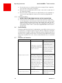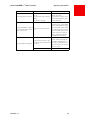
1
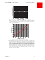
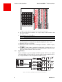
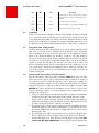
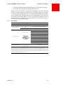
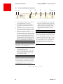
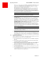
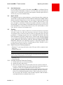
Model 2805
Private Network Solution (PNS) 110 Channel Transmitter
IOM2805
Revision 1.1, December 2003
Instructions for Installation and Use
Read this manual before installing or using this product.
Observe all safety warnings and cautions.
Copyright © 2003 by Force, Incorporated. All rights reserved. Force, Incorporated reserves the right to make changes
to the product described in this document in the interest of document improvement.
825 Park Street Christiansburg, VA 24073 • TEL (540) 382-0462 • FAX (540) 381-0392 • USA (800) 732-5252 • [email protected] • www.forceinc.com
Model 2805 CATVLinx® PNS Transmitter
Preface
WARNING
The optical emissions from the chassis and connected optical fiber are
laser-based and may present eye hazards. Follow all safety precautions
About this Manual
This manual explains how to configure and install the Model 2805 Private Network
Solution (PNS) transmitter. It is intended for engineers and technicians who will
install the 2805 units and their companion receiver(s). While this guide provides
basic information on how to configure and install the units, it assumes that you as
the user are familiar with:
• the installation and manipulation of electronic and fiber optic equipment
• the installation and manipulation of CATV video/audio equipment
This manual is divided into the following sections:
• Section 1, page 1: Describes the Private Network Solution (PNS) transmitter,
lists technical specifications, performance graphs, system applications, and
ordering information.
• Section 2, page 9: Describes the installation of the PNS transmitter and its companion receiver(s).
• Section 3, page 15: Describes the operation of the PNS CATV link, troubleshooting, and user maintenance.
A quick-reference index completes the user manual.
Revision 1.1
ii
Model 2805 CATVLinx® PNS Transmitter
Preface
Related Documentation
•
•
•
•
•
•
•
IOM2807: User manual for Model 2807 Mini-node Receiver
IOM2808: User manual for Model 2808 PDS/PNS CATV Receiver
AN123: North American Television Frequencies
AN128: Care and Feeding of Analog CATV Fiber Optic Links
AN141: System Solutions for CATV HFC Networks
Fiber Optic Reference Guide, 3rd Edition. by David R. Goff (Focal Press 2002):
General theory and operation of fiber optic units.
Web Site: Our web site, http://www.forceinc.com may be used to download
the latest versions of this manual.
Technical Support
If you encounter any kind of problem after reading this manual, contact your local
distributor or a Force, Inc. Applications Engineer. To reach technical support:
On the Web:
http://www.forceinc.com
By Phone (Monday through Friday 8:00 am
to 5:00 pm EST):
USA (800) 732-5252
TEL (540) 382-0462
By Fax:
(540) 381-0392
By Email:
[email protected]
Warranty
Force, Incorporated standard products are warranted to be free from defects in
materials and workmanship, meeting or exceeding factory specified performance
standards for a period of three (3) years from date of purchase.
Force Obligations
Force will, at its discretion and expense, repair any defect in materials or workmanship or replace the product with a new product. Force will, upon receipt of
the return, evaluate the product and communicate to the customer the nature of
the problem, and determine if the claim falls under warranty coverage.
If during the warranty period, Force is unable to repair the product to the original
warranted state within a reasonable time, or if subcomponents of the unit have
been obsoleted or discontinued, then Force has the option to provide an equivalent unit.
Revision 1.1
iii
Model 2805 CATVLinx® PNS Transmitter
Preface
Exclusions
This warranty does not extend to any product that has been damaged due to acts
of God, accident, misuse, abuse, neglect, improper system design or application,
improper installation, improper operation or maintenance, or connection to an
improper voltage supply.
The Force warranty does not cover fuses, batteries, and lamps. Modifications or
alterations of Force products (including but not limited to installation of non-Force
equipment or computer programs), except as authorized by Force, will void this
warranty. Removal or breaking of the seals on the product will also void the warranty. In addition, cost of repair by unauthorized persons within the warranty
period of the product will not be covered by Force, Incorporated. Such repairs
will void the warranty.
Force, Incorporated makes no other representation or warranty of any other kind,
express or implied, with respect to the goods, whether as to merchantability, fitness for a particular purpose, or any other matter. Force, Incorporated’s liability
shall not include liability for any special, indirect or consequential damages, or for
any damages arising from or attributable to loss of use, loss of data, loss of goodwill, or loss of anticipated or actual revenue or profit, or failure to realize expected
savings, even if Force, Incorporated has been advised of the possibility of such
damages. This warranty constitutes Force, Incorporated’s entire liability and the
customer’s sole remedy for defects in material and workmanship.
iv
Revision 1.1
Model 2805 CATVLinx® PNS Transmitter
Contents
Preface................................................................................................................. ii
Section 1 Product Technical Bulletin..................................................................... 1
1.1 Product Overview................................................................................................. 1
1.2 FCC Notice ........................................................................................................... 1
1.3 Optical, Video, Electrical Characteristics ................................................................ 2
1.4 Environmental and Physical Characteristics ........................................................... 2
1.5 Specification Notes ............................................................................................... 2
Figure 1.1 In-Band Frequency Response .......................................................... 2
Figure 1.2 Expanded Frequency Response ....................................................... 3
Figure 1.3 CNR vs. Rx Optical Input and Channel Loading .............................. 4
Figure 1.4 Transmitter Level per Channel vs. Number of Channels .................. 4
Figure 1.5 Transmitter Level per Channel vs. Log10 ......................................... 5
Figure 1.6 Response of Model 2805 RF Power Meter ...................................... 5
Figure 1.7 Top Label Used to Determine RF Input for Transmitter ................... 6
1.6 Applications.......................................................................................................... 6
Figure 1.8 Point-to-Multipoint Private Network Solution ................................. 6
1.7 Part Numbers ....................................................................................................... 7
Section 2 Installation Instructions......................................................................... 9
2.1 General Installation Requirements......................................................................... 9
2.2 Items Provided...................................................................................................... 9
2.3 Items Required ..................................................................................................... 9
2.4 Inspection........................................................................................................... 10
2.5 Equipment Rack Configuration ........................................................................... 10
2.6 Measuring RF Input Levels at the Transmitter ..................................................... 10
2.7 Connections ....................................................................................................... 11
Revision 1.1
v
Contents
Model 2805 CATVLinx® PNS Transmitter
2.8 Front Panel Physical Description.......................................................................... 12
Figure 2.1 Transmitter Front Panel.................................................................12
2.9 Rear Panel Physical Description........................................................................... 13
Figure 2.2 Transmitter Rear Panel .................................................................. 13
2.10 Safety Precautions ............................................................................................ 13
2.10.1 Laser Safety Procedures ....................................................................13
2.11 Shipping and Handling Precautions ................................................................... 14
2.12 Storing the Unit ................................................................................................ 14
Section 3 Operating Instructions ........................................................................ 15
3.1 Connections and Power-up................................................................................. 15
3.2 Performance Verification..................................................................................... 16
3.3 User Maintenance............................................................................................... 17
3.4 Repair Service ..................................................................................................... 17
3.5 Cleaning ............................................................................................................. 17
3.5.1 Optical Connector Cleaning Equipment ..............................................17
3.5.2 Directions for Optical Connector Cleaning ..........................................17
3.5.3 Connector Handling...........................................................................18
3.6 Troubleshooting.................................................................................................. 18
3.7 Problems and Comments .................................................................................... 18
Index ................................................................................................................. 21
vi
Revision 1.1
Model 2805 CATVLinx® PNS Transmitter
Section 1 Product
Technical Bulletin
1.1
Product Overview
The Force, Incorporated CATVLinx® Model 2805 110 Channel CATV Private
Network Solution (PNS) Transmitter is part of a robust system for transferring up to 110 channels of VSB/AM modulated signals over a single-mode optical
fiber. The Model 2805 provides 40-870 MHz of usable bandwidth for video signals
stacked at 6 MHz intervals. A low loss single-mode fiber allows full channel loading
to beyond 20 km while maintaining a good carrier-to-noise ratio. The Model 2805
may be used with the Model 2807 Mini-node receiver for use in return path and
multiple splitter applications or with the Model 2808 PDS/PNS receiver for basic
110 channel CATV transmission. In all cases, the link provides excellent performance for many demanding applications such as broadband LANs, distance
learning, and multiple data services.
1.2
FCC Notice
The Model 2805 has been tested and found to comply with the limits for a Class A
digital device, pursuant to Part 15 of the FCC Rules. These limits are designed to
provide reasonable protection against harmful interference when the equipment
is operated in a commercial environment. This equipment generates, uses, and
can radiate radio frequency energy and, if not installed and used in accordance
with the instructions in this manual, may cause harmful interference to radio communications. Operation of this equipment in a residential area is likely to cause
harmful interference, in which case the user must correct the interference at the
user’s own expense. Compliance with applicable regulations depends on the use
of shielded I/O cables. The user is responsible for procuring the appropriate
cables.
Revision 1.1
1
Model 2805 CATVLinx® PNS Transmitter
Product Technical Bulletin
1.3
Optical, Video, Electrical Characteristics: @ 25 °C, SM Fiber (Note 13)
Min.
Channel Loading
Bandwidth
Operating Wavelength
Optical Output Power
Required Fiber Bandwidth
Input/Output Impedance
Side Mode Suppression Ratio (SMSR)
Backreflection Tolerance
Carrier-to-Noise Ratio (CNR)
Composite Second Order (CSO)
Composite Triple Beat (CTB)
Input Signal Range (per ch.)
Max.
Units
110
40
870
1290
1310
1330
See Section 1.7
2,000
75
30
50
See Figure 1.3
-60
-65
See Figures 1.4 and 1.5
Ch.
MHz
nm
Power Supply Voltage
Power Supply Frequency
Power Dissipation
Fuse (Slow-Blow)
1.4
Typ.
1
2
3
4
5
dB
dB
6, 7
120
240
VAC
8
50
60
Hz
Watts
A
8
20
1.25
9
Environmental and Physical Characteristics
Min.
Operating Temperature Range
Storage Temperature Range
Humidity
Weight
Typ.
0
-20
0
Max.
Units
+45
+70
90
°C
°C
%
lbs.
kg
in.
mm
5.5
2.5
19 W x 1.72 H x 14.1 D
483 x 43.7 x 358
Physical Dimensions
1.5
MHz
Ohms
dB
dB
Notes
See Section 1.5
Notes
See Section 1.5
10
11
12
12
Specification Notes
1) Figure 1.1 shows the typical frequency response of a 2805 link over the specified frequency range. The gain flatness is typically ±1.0 dB over this range.
The flatness is typically less than ±0.1 dB over a standard 6 MHz channel
bandwidth. See Application Note AN123 for additional information on North
American Television Frequencies.
10
Response (dB)
5
0
-5
-10
-15
-20
0
100
200
300
400
500
600
700
800
900
1000
Frequency (Hundreds MHz)
2805T
with 2807R
2805T with
2808R
Figure 1.1 In-Band Frequency Response
2
Revision 1.1
Model 2805 CATVLinx® PNS Transmitter
Product Technical Bulletin
Figure 1.2 shows an expanded view of the frequency response of a typical
2805T/2808R link.
10
8
6
Response (dB)
4
2
0
-2
-4
-6
-8
-10
40
91
142
2805T
with 2807R
193
244 295 346
Frequency (MHz)
397
448
499
550
2805T with
2808R or 2809R
Figure 1.2 Expanded Frequency Response
2) All optical power levels are average values. Output is Class IIIb laser. See part
numbers in Section 1.7, page 7 for available optical power options.
3) Be sure to compute your fiber bandwidth (end-to-end) as well as attenuation.
4) The Model 2805 incorporates an optical isolator in the laser package that
reduces the effect of optical backreflections on the laser performance. However, all analog lasers are affected by optical backreflections. The 2805 can
only achieve published performance levels if the fiber between the
transmitter and receiver has a maximum optical backreflection of -50
dB. Optical backreflection levels above -50 dB will increase the noise floor of
the laser (i.e. decrease the carrier-to-noise ratio), worsen both CSO and CTB
performance, increase passband ripple, and dramatically increase cross modulation. The result will be a noisy, grainy picture with diagonal bars.
Force, Inc. recommends that all fiber connections be SC/APC type,
FC/APC type or fusion spliced. There is some folklore which suggests that
the only critical backreflection is the one closest to the transmitter. Our experience does not support that view. We find that all backreflections matter,
regardless of their distance from the transmitter.
5) Figure 1.3 presents a tremendous amount of performance data for the 2805
link. The horizontal axis is the amount of optical light that reaches the receiver.
(It is not the loss between the transmitter and receiver.) The vertical axis shows
the carrier-to-noise ratio at a given optical input level.
Revision 1.1
3
Product Technical Bulletin
Model 2805 CATVLinx® PNS Transmitter
Figure 1.3 CNR vs. Rx Optical Input and Channel Loading (2805T with 2808R)
The vertical scale is the carrier-to-noise (CNR) ratio. Five curves are plotted
against these axes. The top curve is the typical result when only 5 channels are
transmitted through the link. It can be seen that very high CNR results and in
fact the output is quite usable with receiver optical inputs as low as -12 dBm,
corresponding to 22 dB of optical loss! As the channel loading gets higher, the
maximum achievable CNR drops.
Note that the link CNR is usually specified for a received optical power of
-2 dBm or more. Thus, a 2805TF-SCAP/12 optical transmitter, with an optical
output of +12 dBm, will provide optimal performance with up to 14 dB of
optical loss at full channel loading. If lower channel loading is used, then the
link can operate at higher optical losses and still provide exceptional CNR.
6) The recommended RF input level is shown in Figures 1.4 and 1.5.
WARNING
Exceeding the RF input level may instantaneously destroy the transmitter.
Both figures show the same information, the transmitter level per channel versus the number of channels being transmitted; however, in Figure 1.5 the horizontal scale is a logarithmic scale. This shows that the underlying relationship
is linear if plotted against the logarithm of the number of channels.
Figure 1.4 Transmitter Level per Channel vs. Number of Channels
4
Revision 1.1
Model 2805 CATVLinx® PNS Transmitter
Product Technical Bulletin
Figure 1.5 Transmitter Level per Channel vs. Log10 (Number of Channels)
Figure 1.6 shows the response of the Model 2805 transmitter’s integral RF
power meter. This meter is accessed via pin J4-5 of the 9-pin D-sub connector
on the rear of the transmitter.
Figure 1.6 Response of Model 2805 RF Power Meter
7) Each transmitter has a label such as the one shown in Figure 1.7 that gives the
RF input levels for the transmitter. The individual carrier levels should closely
match each other to ensure consistent performance on all channels. In all
cases, set the composite RF input level so that the RF INPUT LEVEL LED is
green. The RF indicator LED only operates properly for rated channel loading
and a flat input spectrum. To use the chart, look up the channel loading you
will be presenting to the transmitter input and read off the drive level per
video carrier. For instance, with 40-channel loading, each video carrier
should be about +25.0 dBmV.
Revision 1.1
5
Product Technical Bulletin
Model 2805 CATVLinx® PNS Transmitter
Figure 1.7 Top Label Used to Determine RF Input for Transmitter
8) The Tx rear panel power module can accept voltage levels from 120 to 240
VAC at 50 to 60 Hz.
9) Fuse Rating is 1.25 A, Slow-Blow.
CAUTION
Risk of fire. Only use fuses with same type and rating as marked.
10) Most parameters are relatively unaffected by varying temperature. A moving
air environment is recommended at ambient temperatures above +35°C.
11) Humidity is RH non-condensing.
12) Dimensions include L-brackets for mounting the chassis to an EIA 19" equipment rack.
13) The CATVLinx® Model 2805 is optimized for single-mode operation only. Use on
multimode fiber is not recommended, even for short distances, because of the
large amount of modal noise that could result.
1.6
Applications
Figure 1.8 illustrates a point-to-multipoint CATV network. The Force, Inc. Model
1188 Optical Splitter/Coupler splits the output from Model 2805 transmitter, allowing a single transmitter to drive multiple Model 2808 receivers.
Figure 1.8 Point-to-Multipoint Private Network Solution
6
Revision 1.1
Model 2805 CATVLinx® PNS Transmitter
1.7
Product Technical Bulletin
Part Numbers
Part Number
Tx Optical Output
CATV Channel Loading
Optical Connector Type
2805TD-SCSP/06
+6 dBm
110 Channels
SC/APC
2805TD-SCSP/08
+8 dBm
110 Channels
SC/APC
2805TE-SCSP/10
+10 dBm
110 Channels
SC/APC
2805TF-SCSP/12
+12 dBm
110 Channels
SC/APC
2805TG-SCSP/13
+13 dBm
110 Channels
SC/APC
2805TD-SCAP/06
+6 dBm
110 Channels
FC/APC*
2805TD-SCAP/08
+8 dBm
110 Channels
FC/APC*
2805TE-SCAP/10
+10 dBm
110 Channels
FC/APC*
2805TF-SCAP/12
+12 dBm
110 Channels
FC/APC*
2805TG-SCAP/13
+13 dBm
110 Channels
FC/APC*
*Note: The FC/APC interface uses the “wide-key” standard. This means that the units are
optimized for use with FC/APC connectors that have a 2.14 mm wide alignment key. “Narrow-key” FC/APC connectors (2.02 mm) may be used but will produce inferior results. Standard FC/PC connectors have a 2.36 mm wide key and cannot be plugged into either unit.
Revision 1.1
7
Product Technical Bulletin
Model 2805 CATVLinx® PNS Transmitter
Notes:
8
Revision 1.1
Model 2805 CATVLinx® PNS Transmitter
Section 2 Installation
Instructions
2.1
General Installation Requirements
The installation of these units is very simple. There are no special unpacking
instructions, except that care should be taken to handle units gently. Fiber optic
links are sensitive electronics devices that should be handled with care. Like most
electronics, they are susceptible to ESD. Proper ESD techniques, such as wearing
a wrist grounding strap, should be observed at all times when handling a unit. The
units should not be dropped. No assembly is required.
Do not install the equipment near sources of excessive heat, such as furnace outlets or above heat producing units, such as large power supplies and tube-type
equipment. Observe temperature and relative humidity requirements specified in
Section 1.4, page 2.
WARNING
Potentially hazardous uninsulated voltages exist beneath the top panel.
2.2
Items Provided
The following is a list of items provided with each Model 2805 PNS Fiber Optic
Video Transmitter:
Qty.
Mfr.
P/N
AR
Force, Inc.
2805TX-SCXX/XX
1 per
connector
Any
Any
Active Device Receptacle Cap for optical and
RF connectors
2804.342-2
L-Bracket Mounting Ears. Allows the Tx chassis
to be installed in a 19" wide rack.
2 per unit Force, Inc.
1 per unit
2.3
Any
Any
Description
CATVLinx® 110 Ch. PNS Transmitter
Three-wire ground AC power cable.
Items Required
Qty.
Mfr.
P/N
Description
AR
Force, Inc.
2807RX-SFXX
CATVLinx Mini-node CATV Receiver
AR
Force, Inc.
2808RX-SFXX
CATVLinx® PDS/PNS CATV Receiver
4 per unit
Any
Any
6-32 Panhead Mounting Screws with Lock
Washers and Nuts (used to mount the
receivers)
1
Any
Any
Straight Screwdriver
Revision 1.1
®
9
Model 2805 CATVLinx® PNS Transmitter
Installation Instructions
2.4
Qty.
Mfr.
P/N
Description
AR
Any
Any
EIA Standard 19" Grounded Equipment Rack
with Hardware to Install the Transmitter into
the Rack.
9/125 µm Single-mode Fiber
AR
Any
Any
1 per
2807
Force, Inc.
PS200
1 per
2808
Any
Any
Wall-mount Power Supply (Model 2807R only)
Three-wire ground AC power cable.
Inspection
Remove the unit from its shipping container. Any in-shipment damage that may
have occurred should be visually apparent. Look for bent or damaged connectors
or mounting brackets. Claims for damage incurred in shipment should be made
directly to the transportation company in accordance with their instructions. Save
the shipping cartons until installation and performance verification are completed.
2.5
Equipment Rack Configuration
Carefully unpack the chassis, and install it in your earth grounded equipment rack.
Make sure to load the heaviest equipment near the bottom of the rack and the
lightest equipment at the top of the rack. The surface of the equipment rack that
mates to the chassis mounting ears should be conductive. The unit should be
located in an area that provides adequate lighting and is relatively free from dust.
The units are each housed in a single EIA standard 1RU (1.75 inch) rack-mount
chassis. To ensure the unit does not overheat, leave 1RU of space above and
below each installed chassis. When connecting power to the chassis, take care as
to not overload the branch circuit supplying power to whatever is already connected. Also, make sure there are no obstructions in the natural convection air
exhaust or inlet paths.
2.6
Measuring RF Input Levels at the Transmitter
Excessive RF input to a fiber optic CATV transmitter WILL kill the laser even if the
unit is not powered. Lasers can be destroyed by being overdriven for as little as
one nanosecond (10-9 seconds). Because they can be destroyed so quickly, it is
essentially impossible to design a circuit or “fuse” that will blow before the laser is
destroyed. Therefore it is imperative that the RF level be within acceptable limits
BEFORE the cable is attached to the transmitter. See the “Drive Level per Video
Carrier” top label (see Figure 1.7) on the transmitter for the optimum drive levels,
and follow the steps below.
1) Using a spectrum analyzer, determine that the RF level input to the transmitter
is within safety bounds. The unit is shipped with a 20 dB attenuator on the
input to protect against accidental overload on initial hookup. (An additional
20 dB attenuator may be added for absolute security.) This attenuator should
be removed once RF levels are verified to be nominal.
2) The “Drive Level per Video Carrier” chart on top of the transmitter gives the
nominal RF input level for channel loading from 1 to 110 channels. Note that
the chart is in dBmV units per channel, not dBm. DO NOT exceed the values
shown on the chart.
3) The “RF Input Level” LED on the front panel gives a positive indication of the
RF level. If the LED is yellow, the RF level is too low. Increase in 2 dB steps
until the LED turns green. If the LED is red, the RF input level is too high. Disconnect the RF input immediately. Decrease RF levels by 6 dB steps and
10
Revision 1.1
Model 2805 CATVLinx® PNS Transmitter
Installation Instructions
reconnect the RF input until the LED turns yellow or green. If it turns yellow,
increase RF levels by 2 dB steps until the LED turns green.
Ideally, the RF level should be checked with an instrument such as a spectrum
analyzer to verify that the levels are appropriate. If instrumentation is not available
to actually measure the RF levels, Force recommends adding 40 dB of attenuation
at the transmitter input; 40 dB of attenuation will adequately protect the unit from
the highest RF levels that might be seen in a typical CATV installation. Do not
attach the RF cable at this time, just verify the RF levels and/or add the appropriate attenuators at the transmitter input.
2.7
Connections
Connector Name
RF Input
Optical Output
Connector Type
9-Pin D-Sub
Status Output
Connector Function
F Type
RF input to the transmitter
SC/APC (Std.), FC/APC*
Optical output from the transmitter
(Option)
It is imperative that backreflections be controlled to very low levels.
Pin
Function
1
2
3
4
5
6
7
8
9
+5 V Power
RF Level Status
Laser Status
TEC Cooler Status
RF Power Meter
Ground
Ground
Ground
Ground
Accepts a standard IEC
Power Input
power cord.
* Note: The FC/APC interface uses the “wide-key” standard. This means that the units are
optimized for use with FC/APC connectors that have a 2.14 mm wide alignment key. “Narrow-key” FC/APC connectors (2.02 mm), often referred to as JDS compatible, may be used
but will produce inferior results. Standard FC/PC connectors have a 2.36 mm wide key and
cannot be plugged into either unit.
Power/Rear Panel
Revision 1.1
11
Model 2805 CATVLinx® PNS Transmitter
Installation Instructions
2.8
Front Panel Physical Description
A
A.
B.
C.
D.
E.
B
C
Mounting Brackets: Adapts the 1RU chassis for
use in an EIA standard 19” wide rack.
Handles: For easy removal and installation of
1RU chassis with mounting brackets into a 19"
wide rack.
Power Switch: Turns the transmitter on and off.
Power Indicator LED (Green LED): The LED is
on when the unit is receiving AC power and off
when there is no power to the unit.
RF Input Level LED (Tri-colored Green/Yellow/
Red LED): This LED indicates the RF signal input
level into the transmitter. The RF input indicator
is green when the RF signal input is within ±1.5
dB of the optimum input level. When the signal
input falls below the optimum ±3 dB range, the
LED becomes yellow. When the signal input rises
above the optimum range, the LED turns red.
WARNING
DO NOT EXCEED THE RECOMMENDED RF
INPUT LEVEL. EXCESSIVE LEVELS OF RF INPUT
WILL DESTROY THE TRANSMITTER.
F.
D
E
G.
F
G B
A
Laser Status LED (Bi-colored Green/Red LED):
When green, this LED indicates that the laser is
initialized and operating normally. Lights red to
indicate operation above normal operating
temperature range. See Section 1.3, page 2 for
normal operating temperatures or contact
factory.
NOTE
Normally, this LED will be red or change from
red to green in the first ten seconds after power
has been applied to the transmitter. During this
ten second initialization period, the laser is held
in shutdown mode while the rest of the circuitry
initializes. It is then switched to normal operation, and the LED turns green. If the LED turns
red at any time other than in the first ten seconds of operation, this may indicate a laser
failure.
See the warning label on top of the unit (Figure
1.7, page 6) for instructions on acheiving the
recommended RF input level.
Cooler Status LED (Bi-colored Green/Red LED):
When green, this LED indicates that the laser
cooler (TEC) is functioning normally, and the
laser temperature is stable.
NOTE
Normally, this LED will be red or change from
red to green in the first ten seconds after power
has been applied to the transmitter. If the LED
turns red at any time other than in the first ten
seconds of operation, the unit should be turned
off IMMEDIATELY to avoid laser damage.
Figure 2.1 Transmitter Front Panel
12
Revision 1.1
Model 2805 CATVLinx® PNS Transmitter
2.9
Installation Instructions
Rear Panel Physical Description
B
A
C
D
E
1.72"
(43.69)
17.00"
(431.80)
VSB/AM VIDEO
TRANSMITTER
PART NO.
2805TD-SCSP/06
WAVELENGTH
1310 nm
SERIAL NO.
310023
F
825 Park Street
Christiansburg, VA 24073
http://www.forceinc.com
Made in USA
A.
B.
C.
Heat Sink: Dissipates excess heat from the
transmitter.
RF Input (F Connector): RF signal input into the
transmitter. Warning label below advises not to
exceed the RF input level, or the transmitter may
be destroyed.
Optical Output (SC/APC or FC/APC): Optical
output from the transmitter. A dust cover should
be placed over the connector when not in use.
WARNING
OPTICAL LASER RADIATION IS PRESENT AT
THE TRANSMITTER’S CONNECTOR WHEN
THE UNIT IS TURNED ON. AVOID DIRECT EYE
EXPOSURE TO THE INVISIBLE BEAM.
D.
E.
Status Output (DB9 Connector): Transmitter
remote status monitoring connection. See
Section Section 2.7, page 11 for pin connections.
AC Power Input and Fuse Holder: Connects to
primary AC power via a detachable three-wire
grounded power cord.
CAUTION
Connect only to a three-wire grounded outlet.
Do not defeat the purpose of this ground. The
fuse type is 1.5A, Slow Blow.
F.
Unit Serial Number: The unit serial number is a
date code that identifies the start date of the
product warranty. See page iii for Force’s
Standard Warranty.
Figure 2.2 Transmitter Rear Panel
2.10
Safety Precautions
The optical emission from the units are laser-based Class IIIb, and may present eye
hazards if improperly used. NEVER USE ANY KIND OF OPTICAL INSTRUMENT TO VIEW THE OPTICAL OUTPUT OF THE UNIT. As always, be careful when working with optical fibers. Fibers can cause painful injury if they
penetrate the skin.
2.10.1 Laser Safety Procedures
1) ALWAYS read the product data sheet and the laser safety label before powering the product. Note the operating wavelength, optical output power, and
safety classification.
2) If safety goggles or other eye protection are used, be certain that the protection is effective at the wavelength(s) emitted by the device under test
BEFORE applying power.
3) ALWAYS connect a fiber to the output of the device BEFORE power is
applied. Power should never be applied without an attached fiber output. If
the device has a connector output, a connector should be attached that is
connected to a fiber. This ensures that all light is confined within the fiber
waveguide, virtually eliminating all potential hazard.
Revision 1.1
13
Model 2805 CATVLinx® PNS Transmitter
Installation Instructions
4) NEVER look in the end of a fiber to see if light is coming out. NEVER! Most
fiber optic laser wavelengths (1310 nm and 1550 nm) are totally invisible to
the unaided eye and will cause permanent damage. Shorter wavelength
lasers (e.g. 780 nm) are visible and are very damaging. Always use instruments, such as an optical power meter, to verify light output.
5) NEVER NEVER NEVER look into the end of a fiber on a powered device
with ANY sort of magnifying device. This includes microscopes, eye loupes,
and magnifying glasses. This WILL cause a permanent, irreversible burn on
your retina. Always double check that power is disconnected before using
such devices. If possible, completely disconnect the unit from any power
source.
6) If you have questions about laser safety procedures, please call Force, Incorporated for assistance before powering your product. A Sales Engineer or
Applications Engineer may be reached at (540) 382-0462.
7) Laser safety classes for the Model 2805 are as follows:
Class
IIIb
2.11
Wavelength Range
Optical Power Accession Limits
180 nm to 400 nm
Varies with λ and exposure time.
400 nm to 106 nm
0.5 Watt
Shipping and Handling Precautions
The units are, in general, very rugged and can withstand the stresses of most shipping and handling circumstances. However, the following precautions should be
taken:
1) When the units are shipped they should be wrapped in a protective material,
such as bubble wrap, to protect against excessive jarring and to prevent damage to the external finish of the units. Always use packing material to separate
multiple units that are packaged together.
2) Care should be taken not to drop or strike the units in any way, especially
around the optical connectors.
3) The units should never be submersed in any liquid. SEVERE SHOCK HAZARD!
2.12
Storing the Unit
If a unit is to be out of use for an extended period of time, the following steps
should be taken to ensure the preservation of the unit:
1) The storage temperature range is -20°C to +70°C.
2) A low humidity environment is preferable for long term storage.
3) All connectors should be covered with active device receptacle caps.
14
Revision 1.1
Model 2805 CATVLinx® PNS Transmitter
Section 3 Operating
Instructions
3.1
Connections and Power-up
1) Install the links as described in Section 2, page 9 of this document.
2) Measure the RF level BEFORE making any connections to the transmitter. This
measurement is described in Section 2.6, page 10.
3) Clean the optical connectors. See Section 3.5, page 17 for cleaning instructions. Be sure all optical connectors are APC type.
4) Connect the optical fiber to the transmitter and the receiver (see receiver
IOM). Be sure that the fiber has continuity and less than the maximum allowable optical loss. Also be certain that the fiber is the proper size. This product
can only be used with single-mode fiber. The input power to the Rx must be
less than +4.5 dBm. The units will not work back-to-back. The optical input
level to the Rx can be ascertained by checking the color of the “OPTICAL
LEVEL” indicator LED on the Rx.
Red LED = Too much optical power
Green LED = Correct optical power level
Yellow LED = Not enough optical power
5) Connect the RF source (VCR, camcorder, cable television, etc.) to the RF
input on the transmitter.
6) Connect the AC power cord to the back of the transmitter. Because the laser is
thermometrically cooled and is a high performance item, the startup and stabilization sequence is 15-30 seconds long. The front panel of the 2805T has
four LED indicators. One is green only and the other three are tri-color LEDs.
The normal startup sequence is as follows:
Action
Power LED
Unit Off
Dark
RF Input Level LED Cooler Status LED
Dark
Apply Power
Green
Yellow, Note 1
Red, Note 2
Red, Note 2
5-20 Sec.
Green
Yellow, Note 1
Green, Note 2
Red, Note 2
8-14 Sec.
Green
Yellow, Note 1
Green, Note 2
Green, Note 1
Dark
Laser LED
Dark
Note 1: At any time, the RF input will be yellow if the RF input level is too low, green if it
is within the nominal RF input band, and red if the RF input is too high.
Note 2: At any time, if the laser temperature is too high, the COOLER STATUS LED will
change from green to red. This will cause the LASER LED to go red as well.
Revision 1.1
15
Operating Instructions
Model 2805 CATVLinx® PNS Transmitter
When power is first applied, the POWER and RF INPUT LEVEL LEDs should
be green. The COOLER STATUS and LASER LED will light red or change
from red to green to indicate normal operation.
If the “RF Input Level” LED is red, this means the RF level is too high. DISCONNECT THE RF INPUT IMMEDIATELY. Add the attenuator, then reconnect the RF input and observe the LED color. Repeat as necessary until the
LED is green. If the “RF Input Level” LED is yellow, this means the RF level is
too low. Increase the input level until the LED is green.
WARNING
OPTICAL LASER RADIATION IS PRESENT AT THE OPTICAL CONNECTOR WHEN THE
UNIT IS ACTIVATED. AVOID DIRECT EYE EXPOSURE TO THE BEAM.
7) Connect power supply to the receiver.
For Model 2807: The power supply must be from +12 to +16 Volts DC. It is
critical that the supply voltage never drops below +12 Volts. If the voltage
drops below +12 Volts, the link may not operate. Force, Inc. recommends the
Model PS200 wall-mount power supply for use with the Model 2807 receiver.
For Model 2808: The Model 2808 receiver uses an integral AC power supply
which uses a standard 3-wire ground AC power cord.
For all receivers: When power is applied and the link is operational, the
“Optical Level” LED should light green to indicate the optimum optical input
level. If the optical input level is too low, the LED will be yellow. The LED also
doubles as a power indicator.
WARNING
OPTICAL LASER RADIATION IS PRESENT AT THE OPTICAL FIBER THAT ATTACHES TO
THE RECEIVER’S OPTICAL CONNECTOR WHEN THE UNITS ARE ACTIVATED. AVOID
DIRECT EYE EXPOSURE TO THE BEAM.
8) The units are now fully operational. Verify the proper operation of the link by
following the steps in Section 3.2, page 16. No other user adjustment or attention is required. See Section 3.3, page 17 for instructions on maintaining and
cleaning the link. See Section 3.6, page 18 for information on troubleshooting.
3.2
Performance Verification
Once the units have been installed, verify that the picture quality is good. If the
picture quality is not good, there are several likely causes:
1) The optical fiber may have large backreflections. Use an OTDR to examine the
fiber run.
2) There may be non-APC optical connectors somewhere in the system. These
cause unacceptable levels of backreflection.
3) The RF input spectrum may not be flat. It is possible to have a green RF Level
LED even if the input spectrum has a large amount of tilt. All Force CATV
products are designed to operate with a flat input spectrum.
4) There may extraneous (i.e., non-video) signals in the input RF. Be sure to filter
out all non-desirable signals.
5) The optical input power at the receiver may be too low. In this case, the optical status LED will be yellow. See Figure 1.3 for the expected CNR versus the
channel loading and received optical power.
16
Revision 1.1
Model 2805 CATVLinx® PNS Transmitter
3.3
Operating Instructions
User Maintenance
No user maintenance is required. The Model 2805 CATVLinx® 110 Channel Private
Network Solution Transmitter contains no user-serviceable parts and requires no
routine service. Contact the factory if the unit requires warranty repair work. See
Section 3.6, page 18 for troubleshooting.
3.4
Repair Service
For equipment repair or technical assistance, contact Customer Service (800) 7325252 (USA) or (540) 382-0462. A Returned Material Authorization (RMA) number
must be issued by Customer Service before the return of a failed unit. Units should
be returned in their original shipping carton, if available. Always include a complete description of the failure or observed anomalies. All units are marked with
model number and serial number. This identification sticker is placed on the rear
panel (transmitter) or on the product label (receiver). The serial number is a date
code used as a reference for warranty service.
3.5
Cleaning
If the units need to be cleaned, avoid the use of all solvents and use low-pressure
clean air to remove loose dirt. Use low-pressure clean air to clear the connectors
of any debris. Dirty or scratched connector end faces will greatly reduce the unit’s
performance. Foam-tipped swabs such as the 2.5mm Mini Foam Swab offered by
Fiber Instrument Sales (P/N F1-0005) may be saturated with denatured alcohol
(see note below) and inserted into the optical port for cleaning. DO NOT INSERT
A DRY SWAB INTO THE OPTICAL PORT AS THIS MAY DAMAGE THE FIBER
END FACE. Many fiber optic installations experience degraded performance due
to dirty optical connector end faces. The following procedure should be used to
properly clean the optical connector end faces.
3.5.1
Optical Connector Cleaning Equipment
• Kimwipes® or any lens-grade, lint-free tissue. The type sold for eyeglasses work
quite well.
• Denatured Alcohol.
NOTE
Use only industrial grade 99% pure isopropyl alcohol. Commercially available isopropyl
alcohol is for medicinal use and is diluted with water and a light mineral oil. Industrial
grade isopropyl alcohol should be used exclusively.
• 30X Microscope.
• Canned Dry Air.
3.5.2
Directions for Optical Connector Cleaning
1) Fold the tissue twice so it is four layers thick.
2) Saturate the tissue with alcohol.
3) First clean the sides of the connector ferrule. Place the connector ferrule in
the tissue, and apply pressure to the sides of the ferrule. Rotate the ferrule several times to remove all contamination from the ferrule sides.
4) Now move to a clean part of the tissue. Be sure it is still saturated with alcohol,
and it is still four layers thick. Put the tissue against the end of the connector
ferrule. Put your fingernail against the tissue so that it is directly over the ferrule. Now scrape the end of the connector until it squeaks. It will sound like a
crystal glass that has been rubbed when it is wet.
Revision 1.1
17
Model 2805 CATVLinx® PNS Transmitter
Operating Instructions
5) Use the microscope to verify the quality of the cleaning. If it isn’t completely
clean repeat the steps with a clean tissue.
6) Mate the connector immediately! Don’t let the connector lie around and collect dust before mating.
7) Air can be used to remove lint or loose dust from the port of a transmitter or
receiver to be mated with the connector. Never insert any liquid into the
ports.
3.5.3
Connector Handling
1) NEVER TOUCH THE FIBER END FACE OF THE CONNECTOR.
2) Connectors not in use should be covered over the ferrule by a plastic dust
cap. It is important to note that inside of the ferrule dust caps contains a sticky
gelatinous residue that is the by-product of the making of the dust cap. This
residue will remain on the ferrule end after the cap is removed. Therefore it is
critical that the ferrule end be cleaned thoroughly BEFORE it is mated to the
intended unit.
3.6
Troubleshooting
Common problems include lack of continuity in the optical fiber, lack of power (or
reversed power), or improper input levels. The units are designed to work with a
75 Ohm system. A number of indicator LEDs may assist in troubleshooting. These
allow the user to quickly assess the nature of any major unit malfunctions. If problems persist consult the Force, Inc. reference materials listed below, or contact the
factory.
3.7
Problems and Comments
Problem
Check
Comments
Verify that the AC power cord
is firmly attached to the back
of the transmitter, and verify
the integrity of the power
If no AC power is reaching the
cord. Be sure that the primary
unit, the “Power” LED on the
power source has not been
transmitter will be off. Check
inadvertently turned off and
Tx power connection.
that no fuses have blown in
the unit or at the power
source. Plug in the power
cord.
No optical power out of Tx.
No optical power at the Rx.
18
If the unit is receiving AC
power (“Power” LED is green),
check the “Laser” LED. If this
is red, check the “Cooler Status” LED. If the “Cooler Status” LED is green, the problem
may be in the laser. If the
“Cooler Status” LED has also
turned red, the TEC cooler
has failed and the laser is in
danger of overheating.
Remove power from the unit
immediately.
If the Tx “Laser” LED is red but
the “Cooler Status” LED is
green, try turning the transmitter off and back on. The
“Laser” and “Cooler Status”
LEDs should light red within
the first ten seconds of unit
initialization and then turn
green. If either of these LEDs
remains red, contact Force,
Inc. for additional instructions.
Check power at the Tx.
If there is power at the Tx, verify proper fiber is connected to
the Rx, and ensure the integrity of the fiber.
Revision 1.1
Model 2805 CATVLinx® PNS Transmitter
Problem
Low optical power at the Rx.
Operating Instructions
Check
Comments
Check optical output power at
the Tx.
Check optical connector type
(APC).
Check fiber integrity.
This product requires all APC
optical connectors.
Verify that the Tx power is on.
Contact the factory for additional instructions.
No signal out of Rx.; “Optical
Verify the input signal at the
Level” indicator LED is either
Tx.
yellow, red or unlit.
Signal out of Rx is distorted.
A larger signal will cause distortion, and may destroy the
Verify input signal at Tx. The
transmitter. If the RF level is
Tx “RF Input Level” LED should
too high, the LED will be red.
be green.
Adjust the input level until the
LED turns green.
Verify fiber size.
Revision 1.1
The Tx “RF Input Level” LED
should be green. If the LED is
either red or yellow, the signal
input has fallen outside of the
±1.5 dB range. If the Tx “RF
Input Level” LED is green, the
receiver may be in need of
repairs. Contact the factory
for additional instructions.
Use single-mode fiber only.
19
Operating Instructions
Model 2805 CATVLinx® PNS Transmitter
Notes:
20
Revision 1.1
Model 2805 CATVLinx® PNS Transmitter
Index
technical specifications 2–6
RF power meter response 5
tx level per ch. vs. # of ch. 4
tx level per ch. vs. log10 (# of
ch.) 5
A
applications 6
C
cleaning the optical connector 17
cleaning the unit 17
cnr vs. rx optical input and channel
loading diagram 4
connection
optical 13
connections 15
optical 11
power 11, 13
RF 11, 13
status 11, 13
connections. See installation.
D
diagrams
performance
cnr vs. rx optical input and
channel loading 4
drive level per video carrier 6
expanded frequency response 3
in-band frequency response 2
Revision 1.1
E
expanded frequency response diagram
3
F
FCC notice 1
front panel physical description 12
H
handling precautions 14
handling the optical connector 18
I
in-band frequency response diagram 2
inspection 10
installation 9–14
connection
RF 13
connections 11, 15
alarm 11
optical 11, 13
21
Model 2805 CATVLinx® PNS Transmitter
Index
optical interface 3
power 11, 13
RF 11
status 11, 13
general requirements 9
inspection 10
items provided 9
items required 9
maintenance 17
performance verification 16
power-up 15
rack configuration 10
rear panel description 13
RF input levels into the transmitter
6, 10–11
R
rear panel description 13
receiver part numbers 9
repair service 17
RF input levels, measurement 10
S
safety precautions 4, 6, 9, 12, 13
laser safety ii, 13
shipping precautions 14
storage precautions 14
T
operating instructions 15–20
optical interface. See installation,
connections.
ordering information 7
technical specifications
electrical 2
optical 2
performance graphs
expanded frequency response 3
physical 2
video 2
technical support. See troubleshooting
transmitter part numbers 7, 9
troubleshooting 18–20
repair services 17
technical support iii
tx level per ch. vs. # of ch. diagram 4
tx level per ch. vs. log10 (# of ch.)
diagram 5
P
W
part numbers
receiver 9
transmitter 7, 9
performance
performance verification 16
power-up 15
power-up sequence 15
product overview 1
product TB 1–7
warranty iii
L
laser safety precautions ii, 13
M
maintenance 17
measuring RF input levels at the
transmitter 10
O
22
Revision 1.1