1
US006976052B2
(12)
(54)
(75)
United States Patent
(10) Patent N0.:
Tompkins et al.
(45) Date of Patent:
SPA CONTROL SYSTEM
Inventors: Michael E. Tompkins, Houston, TX
.
(73)
3,781,925 A
1/1974 Curtis et al.
3,836,959 A
9/1974 Pao et al. ................. .. 340/148
3,837,016 A
9/1974 Schindler et a1~ -
3,886,544 A
5/1975 Narodny
(Us)
3,910,678 A
3,937,952 A
_
.
3,972,603
Asslgnee' Balboa Instruments’ Inc" Tusnn’ CA
Notice:
Dec. 13, 2005
(Us); Michael J_ Green, Houston, TX
(Us)
(*)
US 6,976,052 B2
A
8/1976
352/4
4,048,852 A
9/1977 Sakakibara et al. ..... .. 73/193 R
FOREIGN PATENT DOCUMENTS
32 09 635 A1
DE
_
9/1983
3306807
DE
8/1984
33 08 862 A1
C
9/1984
t'
d
( on mue )
US 2001/0029407 A1 Oct. 11, 2001
_
. . . . . . . . ..
(Continued)
(21) Appl. N0.: 09/761,264
Jan. 16, 2001
. . . . . . . . .
1/1977 Stephenson ............ .. 235/1511
DE
Prior Publication Data
Lubinec
. . 350/96
250/227
4,001,557 A
U.S.C. 154(b) by 373 days.
(65)
340/365
10/1975 McCartney
2/1976 Ripley et al. ..
Subject to any disclaimer, the term of this
patent is extended or adjusted under 35
(22) Filed:
~~ 4/172-17
OTHER PUBLICATIONS
_
Motorola Microprocessor, Microcontroller, and Peripheral
Related US. Application Data
Data, V01' 1, 1988'
(63) Continuation of application No. 08/822,179, ?led on Mar.
Newspaper article: Ma_ry Kay Sef? “Bathrooms are getting
20, 1997, now Pat. No. 6,253,227, which is a continuation
pretty splashy, San Dlego Unlon Tr1bune> May 9, 1989
of application No. 08/703,177, ?led on Aug. 23, 1996, now
_
abandoned, which is a continuation of application No.
(Continued)
08/327,927, ?led on Oct. 24, 1994, now Pat. No. 5,559,720,
which is a continuation of application No. 08/225,282, ?led
'
'
1V1
On
Jan. 11, 1994, now Pat. N0. 5,361,215, which is a
continuation of application No. 07/224,869, ?led on Jul. 26,
P73”?
Examl'fr Oust?‘ hiFMlekyd
Pn L &
( ) Home)’; gem’ Or Wm
uWl er a on 66
1988, now abandoned, which is a continuation-in-part of
application No. 07/054,581, ?led on May 27, 1987, now
Utecht LLP
abandoned_
(51)
(52)
(58)
Int. Cl.7 .............................................. .. G06F 13/00
US. Cl. .......................... .. 709/201; 4/493; 210/169
Field of Search ....................... .. 210/169; 709/201;
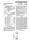
An improved spa control system is disclosed, The invention
describes a spa control system which calculates the time
required to heat the Water in the spa system to a desired
392/465, 466, 485, 498; 219/497, 481,
489; 4/538, 539, 540, 5411, 541,2, 541,3,
temperature. From that information, the heating rate of the
spa system can be determined, and the heating element of
493
the spa system can be activated at the proper time to raise the
temperature of the water to a selected temperature by a
(56)
References Cited
desired time. The spa system also monitors information
which might show errors in the operation of the spa system
US. PATENT DOCUMENTS
such as a blockage in the ?ow of water over the heating
3,400,374 A
3,459,925 A
9/1968 Schumann ............. .. 340/1725
8/1969 Goosey et al. ..
235/151
3,498,286 A
3/1970 Polanyi et al. ............... .. 128/2
element 1“ the Spa System‘
24 Claims, 11 Drawing Sheets
SPA CONTROL PANEL
0
ii
0
U
&
A FLOW SWITCH
SYSTEM
‘10/220 VAC :i‘ {NTERCONNECTION
INPUT
PANEL
— TEMP FOR WATER
— Ph
PROBE
i TEMP FOR HEATING
ELEMENT
n
US 6,976,052 B2
Page 2
US. PATENT DOCUMENTS
4,071,745 A
4,114,442 A
47116228 A
4,428,528 A
1/1984 Renault .................. .. 236/46 R
1/1978 Hall ......................... .. 364/104
9/1978 Pratt ......................... .. 73/341
4,432,210 A
4,436,610 A
4,446,913 A
2/1984
3/1984
5/1984
9/1978 Hudspeth 6‘ a1"
4 450 829 A
5/1984 Morita et al
Lester
................. ..
"
128/2.05 R
7
10/1978
4,122,719 A
10/1978 Carlson et al. ............. .. 73/342
4 123 796 A
“V1978
4,480,312 A
10/1984 Wingate ................... .. 364/557
4:133:036 A
1/1979
4,489,235 A
12/1984 Porteous ................... .. 219/437
4,158,965 A
6/1979
4,494,526 A
Wurst 61 al. .............. .. 126/419
4,161,880 A
4,162,486 A
7/1979
7/1979
4,497,031 A
4,504,010 A
1/1985 Froehling et al. ......... .. 364/505
3/1985 Sukimoto et al.
. 236/46 F
4’466’749 A
.
126/362
4,121,574 A
.
7
Saito ......................... .. 62/126
EnZer et a1' ~~~~~~~~~~~~~~ u 204/400
Krocker ~~~~~~~~~~~~~~~~~~~~~ " 165/12
'
""""""" "
8/1984 C“_nmngham et a1‘
4,169,293 A
10/1979
4,508,261 A
4/1985
4,174,517 A
11/1979
4,527,246 A
7/1985 Masson
4,198,676 A
4,200,910 A
4/1980
4/1980
4,527,247 A
4,529,033 A
7/1985 Kaiser et al. ............. .. 364/550
7/1985 Blum ........................ .. 165/39
4,204,204 A
5/1980
4,212,078 A
4,215,398 A
7/1980 Games et al. ............. .. 364/900
7/1980 Burkett et al. ............ .. 364/101
4,237,562 A
.
4,539,632 A
12/1980 DuPont
4,265,298 A
4,266,599 A
5/1981 Sumner, Jr. et al. .......... .. 165/2
5/1981 Saunders et al. ............ .. 165/2
4,554,688 A
4,563,780 A
Blank .... ..
374/134
364/505
9/1985 Hansen et al.
11/1985
1/1986
.. 236/20 R
364/143
Puccerella ................... .. 4/191
Pollack ........................ .. 4/192
4,564,962 A
1/1986 Castleberry et al.
4,574,871 A
4,594,500 A
3/1986 Parkinson et al. ........... .. 165/1
6/1986 Wright ..................... .. 219/296
4/543
4,269,261 A
5/1981 KountZ et al.
165/2
4,600,879 A
7/1986 Scully et al.
4,270,693 A
4,274,145 A
6/1981 Hayes .................... .. 236/46 F
6/1981 Hendricks et al. ........ .. 364/557
4,607,787 A
4,610,142 A
8/1986 Rogers, Ill ................. .. 236/11
9/1986 Davis
...................... .. 62/3
4,274,705 A
6/1981
. 350/96.15
4,618,091 A
10/1986
4,275,266 A
6/1981 Lasar .................... .. 179/1 VC
Miller ......... ..
4,621,613 A
11/1986 Krumhansl
4,275,382 A
6/1981
4,625,096 A
11/1986
4,276,603 A
6/1981 Beck et al. .
4,276,925 A
4,284,126 A
7/1981
8/1981
4,290,551 A
9/1981 Johnstone
Jannotta ................... .. 340/151
324/585 A
BuZZi .................... .. 236/12.12
Fletcher .................... .. 239/331
. 364/477
4,638,147 A
1/1987 Dytch et al. .
Palmieri .................... .. 165/12
Dawson .................. .. 165/11 A
4,642,785 A
4,644,478 A
2/1987 Packard et al. ........... .. 364/557
2/1987 Stephens et al. .......... .. 364/550
. 236/9 R
4,645,908 A
2/1987 Jones
.. 307/28
.. 165/12
4,663,613 A
4,669,049 A
5/1987 Raleigh et al. ........... .. 340/607
5/1987 Kosednar et al. ......... .. 364/557
. 364/557
4,676,914 A
6/1987 Mills et al. ...... ..
210/741
364/557
4,682,728 A
7/1987 Oudenhoven et al.
236/12.12
4,292,542 A
4,293,028 A
9/1981
10/1981
Bajka ....... ..
Knoll .......... ..
4,298,946 A
11/1981 Hartsell et al.
4,300,199 A
11/1981 Yoknis et al.
4,300,909 A
11/1981 Krumhansl
4,307,576 A
12/1981 Takano et al. .
Mandl ...... ..
392/485
. 219/378
.. 23/230
4,685,307 A
8/1987 Jones ........................ .. 62/160
62/204
4,688,273 A
8/1987 Lyng .
.. 165/22
4,693,415 A
9/1987
.. 236/46 R
.. 236/46 R
4,696,428 A
4,700,884 A
9/1987 Shakalis ................ .. 236/12.12
10/1987 Barrett et al.
236/12.12
Sturm
4/192
4,308,911 A
1/1982
................... .. 236/12.12
4,308,991 A
4,314,665 A
1/1982 Peinetti et al.
2/1982 Levine ........... ..
4,316,256 A
2/1982 Hendricks et al.
364/505
4,702,305 A
10/1987 Beckey et al. .............. .. 165/12
4,319,711 A
4,322,031 A
3/1982 Barker et al.
.. 236/46 R
3/1982 Gehlert ................ ..
236/12 R
4,706,882 A
4,711,392 A
3/1982 Bajka
4,713,525 A
11/1987 Barnard .................. .. 236/46 R
12/1987 Kidouchi et al.
236/12.12
12/1987 Eastep ...................... .. 219/308
4,324,138 A
4/1982 Davis et al. ................ .. 73/341
4,713,783 A
12/1987 Fletcher .................... .. 364/557
4,330,081 A
5/1982 McMillan
236/12 R
4,718,248 A
1/1988 Fisher
4,334,518 A
6/1982 Ort .......................... .. 126/132
4,725,001 A
2/1988 Carney et al. .............. .. 236/11
4,349,434 A
4,353,412 A
9/1982 JaWorski
10/1982 Krumhansl ................ .. 165/59
4,742,456 A
4,752,141 A
5/1988 Kamena ................... .. 364/400
6/1988 Sun et al.
374/161
4,353,502 A
10/1982 Myers .................... .. 236/47
4,757,943 A
7/1988 Sperling et al. ....... .. 236/12.12
4,361,274 A
11/1982 Raleigh et al.
4,762,980 A
8/1988 lnsley ...................... .. 219/307
4,322,297 A
*
4,368,991 A
4,370,534 A
1/1983 HentZe ...................... .. 374/12
1/1983 Brandon ............ .. 219/10.55 A
4,763,365 A
4,768,705 A
8/1988 Gerondale et al.
9/1988 Tsutsui et al.
4,381,031 A
4/1983 Whitaker et al.
4,770,037 A
9/1988 Noir et al.
.. 73/204
4,381,075 A
4/1983 Cargill et al. ............. .. 237/8 R
4,770,540 A
9/1988 Chague et al. ..
.. 374/17
4,382,544 A
5/1983 Stewart ....... ..
.. 236/46 R
4,773,008 A
4,385,724 A
5/1983 Ramsauer et al.
.. 236/25 A
4,775,245 A
10/1988 Hagerman et al
4,386,649 A
6/1983 Hines et al. ................ .. 165/12
4,775,776 A
10/1988 Rahn et al. ............... .. 219/388
11/1988 Hancock
9/1988 Schroeder et al. .
4,398,789 A *
8/1983 Pryor
4,780,917 A
4,403,296 A
9/1983 Prosky ..................... .. 364/573
4,797,958 A
1/1989
4,404,697 A
9/1983 Hatcher
4/492
4,809,516 A
3/1989 Jones
4,406,401 A
9/1983 Nettro ..
. 236/12.12
4,854,498 A
8/1989 Stayton
4,406,550 A
4,409,662 A
9/1983 Gray
10/1983 Rao ............ ..
4,409,694 A
10/1983 Barrett, Sr. et al. ..
4,410,791 A
10/1983
Eastep ............... ..
4,420,032 A
12/1983 Van Koppen et al.
4,420,811 A
12/1983 Tarnay et al. ..
4,420,947 A
12/1983
. 236/12.12
364/400
374/134
GuZZini ....................... .. 4/542
11/1989 Baker
.. 62/160
. 236/12.12
. 374/110
RE33,119 E
. 364/557
5,226,408 A
7/1993
4/545
5,245,221 A
9/1993 Schmidt et al. .
307/112
. 219/307
5,278,455 A
1/1994
307/139
Drysdale
Hamos ..... ..
374/102
. 126/247
165/1
5,283,915 A
2/1994 Idland et al.
. 364/510
5,287,567 A
2/1994 Eash et al.
4/493
62/160
5,333,325 A
8/1994
4/584
4,421,269 A
12/1983 Ts’ao .................... .. 236/12.12
5,341,527 A
8/1994 Schmidt et al. .
4,421,270 A
12/1983 Raleigh et al.
5,361,215 A
Yoshino
.....
. . . ..
Levien et al.
. 4/541.1
4/592
11/1994 Tompkins et al. ........ .. 364/505
US 6,976,052 B2
Page 3
RE35,018 E
8/1995 Homan .................. .. 236/12.12
5,457,826 A
10/1995 Haraga et al. .......... .. 4/541.4
2
¥omptlns 6: ai- ~~~~~~~~ " 364/505
6,014,677 A
1/2000 Hayashi et al. ........... .. 707/501
,
,
omp
ms e
a .
FOREIGN PATENT DOCUMENTS
DE
EP
EP
EP
FR
GB
GB
GB
GB
JP
JP
JP
JP
JP
JP
JP
JP
JP
JP
JP
JP
JP
JP
JP
35 11 499
0 009 249
0 286 941
88 10 5389
2 562 687
2 094 503
2133258
2 204 966
2 211 331
53-125164
53-125164
55-112646
55-135912
57-157954
57-182044
57-182044
58-75660
58-109996
58-119037
58-179728
60-213731
59-72892
59-215535
60-14677
A1
A1
A
A
A
A
10/1986
9/1979
10/1988
4/1998
10/1985
9/1982
12/1983
11/1988
6/1989
2/1978
11/1978
2/1980
2/1980
2/1982
2/1982
11/1982
2/1983
2/1983
2/1983
2/1983
2/1983
2/1984
2/1984
1/1985
JP
60-8652
2/1985
JP
JP
JP
JP
JP
JP
JP
JP
JP
JP
JP
JP
JP
JP
JP
60-14041
60-14042
60-17657
60-26239
60-148691
60-155848
60-186644
61-107048
61-110842
61-15444
61-11551
61-13254
61-18467
61-184354
62-108954
2/1985
2/1985
2/1985
2/1985
2/1985
2/1985
2/1985
2/1985
2/1985
1/1986
2/1986
2/1986
2/1986
2/1986
2/1987
OTHER PUBLICATIONS
Advertising for Applied Computer Controls SC 100 spa
Controllen
Advertising for ACC Spa controller products with photos of
_
-
a SP 200 Skld pack’ etc‘
Photgraph of an ACC SC—200 circuit board.
Photograph of SC—200 spa control board connected to
control panel and thermistor.
Photograph of SC—200 control panel.
Software code for SC—200 spa control board.
SC—200 Operation and Instruction Manual.
Electronic Engineer’s Handbook, McGraw—Hill Book Co.,
1982.
Compool CP2000 “The Complete Pool, & Spa Control
System”.
Plaintiff Siege’s Opposition to Defendants’ Motion for Judg
ment as a matter of Law; Case No. H—94—3180.
Plantiff Siege’s Opposition to Defendants’ Requested Find
ings of Fact and Conclusions of Law Regarding Inequitable
Conduct; Case No. H—94—3180.
Plaintiff Siege’s Motion to Enjoin Defendants from Further
Infringement of Siege’s United States Patent No. 5,361,215;
Case No. H—94—3180.
Deposition of Ronald G. Bliss; Case No. H—94—3180.
Defendants’ Proposed Findings of Fact and Conclusions of
Law Regarding Inequitable Conduct; Case No. H—94—3180.
Plantiff Siege’s Opposition to Defendants’ Motion for Judg
ment as a Matter of Law; Case No. H—94—3180.
Memorandum in Support of Defendants’ Requested Find
ings of Fact and Conclusions of Law Regarding Inequitable
Conduct; Case No. H—94—3180.
Defendants’ Notice of Patent Invalidity Pursant to 35 USC
§282; Case No. H—94—3180.
Defendants’ Response to Plaintiff’s Bench Memorandum on
Claim Construction; Case No. H—94—3180.
Defendants’Response to Plaintiff’s Bench memorandum re
35 USC §102(g) Defense; Case No. H—94—3180.
Siege’s Memorandum of Law on the Issue of Claim Con
struction; Case No. H—94—3180.
Siege’s Supplemental memorandum of Law on the Con
struction of Claims 1 and 37; Case No. H—94—3180.
Siege’s Bench Memorandum on Defendants’ §102(g)
Defense; Case No. H—94—3180.
Memorandum of Points and Authorities in Opposition to
Siege’s Motion for Dismissal of Complaint; Case No.
SACV9696—834—LHM.
Newsweek article: Givens and Springen, “Splish, splash, it’s
more than a bath,” May 5, 1986.
Newspaper article: Teresa Foreman, “Pieces of Yesterday
Graced with Touches of Tomorrow,” The Record, May 4,
1986.
Declaration of David Cline in Support of Opposition to
Siege’s Motion for Dismissal of Complaint; Case No.
SACV96—834—LHM.
Declaration of Joseph A. Walker in Support of Opposition to
Seige’s Motion for Dismissal of Complaint; Case No.
Newspaper article: “Spring Home ’86; Shorts and ?llers,”
UPI, BC Cycle, Mar. 27, 1986.
SACV96—834—LHM.
Newspaper article: “Dial a dub dub,” The Financial Post
Siege’s Motion for dismissal of Complaint and in Response
to the Court’s Request for Brie?ng of the Stay Issue; Case
(Toronto), Mar. 22, 1986.
Newspaper article: Frederika Randall, “Designers put the
bathroom in its place high tech makes it a nice place to
visit,” Chicago Tribune, Mar. 9, 1986.
Memorandum of Points and Authorities in Opposition to
No. SACV96—834—LHM.
Declaration of Joseph A. Walker in Support of Opposition to
Siege’s Motion for Dismissal of the Complaint; Case No.
SACV96—834—LHM.
Newspaper article: Frederika Randall, “Baths of the future at
a fair in Milan,” New York Times, Feb. 13, 1986.
Declaration of David Cline in Support of Opposition to
Siege’s Motion for Dismissal of the Complaint; Case No.
Agreement between Siege Industries, Inc. and ICS Devel
opment, Inc., dated Mar. 23, 1987.
Jury instructions and questions, Siege Industries, Inc. v.
Clark Mfg, Inc., et al.
Declaration of Joseph Stone in Support of Opposition to
Siege’s Motion for Dismissal of the Complaint; Case No.
SACV96—834—LHM.
SACV96—834—LHM.
US 6,976,052 B2
Page 4
Ex Parte Application to File First Amended and Supplemen
Ex Parte Application to Extend Time to File Notice of
tal Complaint for Declaratory Judgement of Noninfringe
Appeal; memorandum of Points and Authorities in Support
ment, Invalidity and Unenforceability of Patents; Case No.
Thereof; Case No. SACV 96—834—LHM.
Declaration of Joseph A. Walker in Support of Ex Parte
Application to Extend Time to File Notice of Appeal; Case
SACV 96—834—LHM.
Declaration of Joseph A. Walker in Support of Ex Parte
Application to File First Amended and Supplemental Com
plaint for Declaratory Judgement of Noninfringement,
Invalidity and Unenforceability of Patents; Case No. SACV
96—834—LHM.
Notice of Motion and Motion for Relief from Order Dis
missal Complaint and for Reconsideration; Memorandum of
Points and Authorities and Declaration of Joseph A. Walker
in Support Thereof; Case No. SACV 96—834—LHM.
Notice of Motion to File a Second Amended and Supple
mental Complaint; Memorandum of Points and Authorities
and Declaration of Joseph A. Walker in Support Thereof;
Case No. SACV 96—834—LHM.
No. SACV 96—834—LHM.
AnsWer of Defendant Balboa Instruments, Inc.; Case No.
H—96—3105.
Plaintiff’s Reply to Defendants’s Opposition to Plaintiff’s
Motion for Reconsideration;
Case No. SACV
096—834—LHM.
Intel MCS—40 User’s Manual for Logic Designers, Second
Edition, Third Printing, Mar. 1975.
CMOS Databook, National Semiconductor Corporation,
1984.
* cited by examiner
U.S. Patent
Dec. 13, 2005
Sheet 1 0f 11
US 6,976,052 B2
SPA CONTROL PANEL
0
0
Q38
O
O
O
O
FLOW SWITCH
110/220 VAC
INPUT
SYSTEM
INTERCONNECTION
PANEL
TEMP FOR WATER
____
Ph PROBE
TEMP FOR HEATING
ELEMENT
PUMP
HEATER
FIG.
BLOWER
1
LIGHT
U.S. Patent
Dec. 13,2005
Sheet 2 0f 11
US 6,976,052 B2
MICROCOMPUTER
EPROM
DIGITAL IN
MEMORY
——~
RAM
HEATER
DIGITAL OUT
MEMORY
M
RTC
ANALOG IN
DISPLAY
SIGNAL
INTF
COND
I
—
PUMP
BLOWER
TEMP-HEATER
TEMFJ—WA'I ._R
pH
I
DISPLAY
FLOW
KEYBOARD
INTF
I
KEYBOARD
MAIN PROGRAM
KEYBOARD
' PIO
MONITOR
CONTROL
DISPLAY
CONTROL
OUTPUT
CONTROL
ALARM
CONTROL
INPUT
SCANNING
ANALOG
pH
CONVERSION
ALGORITHM
RTC
CONTROL
FIG. 4
U.S. Patent
Dec. 13,2005
O
Sheet 4 0f 11
US 6,976,052 B2
59V620
Em%
O
nuO@25 :
.Uhmm
5%m251S;75
U.S. Patent
FIGJ: -
Dec. 13, 2005
OWr-u/f ffow or [Dnfrv/
N/W
Sheet 5 0f 11
US 6,976,052 B2
U.S. Patent
Dec. 13, 2005
Sheet 7 0f 11
FIC.00
(7.264?’
MR; [/0111- Def‘ccf’
US 6,976,052 B2
U.S. Patent
FIG IO
Dec. 13,2005
Sheet 9 0f 11
US 6,976,052 B2
U.S. Patent
Dec. 13,2005
Sheet 10 0f 11
US 6,976,052 B2
Fr- It
a;
*6. i3
Tiwer IKTWFHPT
P)
i M .l’zybsml
UAR
IPODJ€IFVEP~|
an‘ um
3 pp” nLc l
*° 552°”
U.S. Patent
Dec. 13,2005
Sheet 11 0f 11
US 6,976,052 B2
US 6,976,052 B2
1
2
SPA CONTROL SYSTEM
ef?ciently controls the operation of the spa and is not
adversely affected by the corrosive environment surround
ing the spa. The spa temperature control system generally
comprises a heating element, a sensor for detecting the
temperature of the Water, and a microcomputer for process
This application is a continuation of US. patent appli
cation Ser. No. 08/822,179 ?led Mar. 20, 1997, now US.
Pat. No. 6,253,227, Which is a continuation of US. appli
cation Ser. No. 08/703,177 ?led Aug. 23, 1996, noW
abandoned, Which is a continuation of US. application Ser.
No. 08/327,927 ?led Oct. 24, 1994, now US. Pat. No.
5,559,720, Which is a continuation of US. patent application
Ser. No. 08/225,282 ?led Jan. 11, 1994, now US. Pat. No.
5,361,215, Which is a continuation of US. patent application
Ser. No. 07/224,869 ?led Jul. 26, 1988, noW abandoned,
Which is a continuation-in-part of US. patent application
Ser. No. 07/054,581, ?led May 27, 1987, noW abandoned,
each of the above related applications and patents being
ing signals generated by said sensor and for activating and
deactivating the heating element. In one embodiment of the
invention, the microcomputer assesses the time necessary to
heat Water from an initial temperature to a selected tem
10
can be calculated. The heating rate can be stored by the
microcomputer and can be used to determine the star time
necessary to heat the spa Water from an initial temperature
to a selected temperature by a desired time. In the same or
15
incorporated herein by reference.
monitored to detect problems in the system.
BRIEF DESCRIPTION OF THE DRAWINGS
20
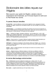
FIG. 1 illustrates a schematic block draWing of the spa
control system.
FIG. 2 illustrates a block diagram of the microcomputer
and its associated components.
control panel to effectively control various operating func
tions of the spa.
BACKGROUND OF THE INVENTION
another embodiment of the invention, the temperature dif
ference betWeen tWo sensors in the spa system can be
FIELD OF THE INVENTION
This invention relates to the development of a spa control
system. More particularly, this invention relates to a spa
control system Which uses an interconnection panel and a
perature. From this information, the heating rate of the Water
25
FIG. 3 illustrates a block diagram of the spa control
The design of systems to control spas is complicated by
the environment of the spa. Typically, spa control systems
system ?eld interconnection panel.
contain heating elements, controls, sWitches, and Wiring
softWare Which operates the spa control system through the
harnesses Which deteriorate When eXposed to moisture or
eXtreme levels of humidity and a hostile chemical environ
ment. Since the chemically treated, heated Water of the spa
FIG. 4 illustrates a functional block diagram of the
microcomputer.
30
raises the humidity level and produces corrosive gases, the
atmosphere surrounding the controls of the spa unit is
FIG. 6 illustrates the overall softWare control of the spa
control system.
inherently corrosive to spa control systems.
The accuracy of the temperature of the spa Water is
essential to the safety and comfort of the spa user. This
35
temperature is dif?cult to accurately control, since the tem
perature of the Water can vary rapidly depending on the
number of spa users, the ambient temperature of the air, and
other environmental factors. To conserve energy, the spa
40
temperature is customarily raised to the desired level shortly
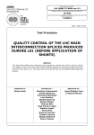
FIGS. 7—13 illustrate ?oWcharts of various softWare func
tions of the spa control system.
FIG. 14 illustrates diagrammatically a system constructed
in accordance With the preferred embodiment.
DESCRIPTION OF THE PREFERRED
EMBODIMENTS
FIGS. 1 and 2 illustrate a block diagram of the overall spa
control system. The spa control system uses an intelligent
before the eXpected use of the spa, and is not maintained at
a constant temperature When the spa is unattended. Depend
ing on the use of the spa, the temperature of the spa Water
may be cycled several times per day. During these cycles,
FIG. 5 illustrates one embodiment of a display panel for
the operation of the spa control system.
microcomputer 10 to monitor and control the operation of
45
the spa. The system uses solid state electronic components
Which eliminate many of the problems associated With
traditional mechanical timer and relay control systems. The
the control of the Water temperature is dif?cult to maintain
Without overheating or underheating the Water. Typically, a
spa control system merely heats the Water With a heating
element until the temperature of the Water matches a pre
determined setting selected by the spa user. Since the heating
element is not turned off until that desired Water temperature
is reached, the residual heat in the heating element may
increase the temperature of the Water beyond the actual
temperature desired. Conversely, the location of the tem
use of solid state electronic components increases the reli
ability of the system and reduces the maintenance necessary
to maintain the spa in operable condition.
Referring to FIGS. 1 and 14, the external system generally
comprises a spa control panel 12 Which is connected to a
system interconnection panel 14. The system interconnec
tion panel 14 is also connected to poWer input 16, to various
perature sensor may be located in the spa in such a fashion 55 sensors Which detect parameters such as How rate 18,
temperature 20, 21 and pH 22 of the Water, and also the
that it does not sense the actual, median Water temperature.
mechanical and electrical components of the spa, such as the
Accordingly, the heating element may be turned off before
pump 24, heater 26, bloWer 28, and lights 30. The heater 26
the temperature of the Water reaches the desired level.
Present spa controllers operate on line voltages Which can
present a safety haZard to the spa users. To meet desired
may be interlocked to the pump 24 so that the pump 24 is
60
safety speci?cations, these controls are typically located
aWay from the sap, hoWever, this separation is inconvenient
continuously pumping Water over the heating element 29 of
the heater 26 While the heater 26 is activated. This prevents
a “hot spot” from developing in the spa system Which could
damage the components of the spa or give erroneous mea
to the spa user.
surements.
SUMMARY OF THE INVENTION
The present invention overcomes the foregoing difficul
ties by providing a spa control system Which accurately and
65
The system is a microcomputer-based system. In addition
to the microcomputer 10, the system utiliZes several other
devices. While the control program runs on the microcom
US 6,976,052 B2
3
4
puter 10, it is directly responsible for the management of the
system hardware. The following description brie?y summa
riZes the major devices:
The keyboard 48 (FIGS. 1, 2 and 5) shoWn is a ?at panel
membrane style Which is incorporated into the front panel.
One type of keyboard 48 has ten push-buttons 50 and nine
translucent cut-outs for backlighting of Light Emitting
NOVRAM 32 This is a nonvolatile RAM device that is
used to store the system calibration values as Well as
providing RAM expansion for the microcomputer 10.
Diodes (LEDS) 52. The keyboard 48 is mounted on beZel 54
to provide a ?rm surface When depressing the buttons 50.
An EEROM image of the calibration values is stored
The keyboard interface 56 provides circuitry Which trans
When the poWerfail interrupt is posted to the micro
computer 10 and restored When the microcomputer 10
poWers up.
A/D 36 This is an analog to digital converter that converts
mits information from the keyboard 48 to the microcom
puter 10. The keyboard interface 56 acts as an array of on/off
10
voltage inputs after signal conditioning at 37 to digital
numeric representations. It provides three values: spa
temperature 21, heater temperature 20 and pH value 22.
sWitches that correspond to each keypad. The microcom
puter 10 scans these sWitches as on/off, sWitch type input
bits.
The Digital Outputs 58 drive the external spa devices,
such as the pump 24, heater 26, bloWer 28 and other
DISPLAY DRIVER or INTERFACE 38 This device 15
auxiliary devices. The loW voltage signals are optically
accepts a bitstream 39 from the microcomputer and
isolated at 60 and then drive a TRIAC device 62 Which
drives the display 40 for the spa control panel 12. Abit
is input for each segment on the display.
provides the high voltage and high current required by the
external devices.
FIG. 2 illustrates a block diagram of the spa control
system and its associated components. The electronics in the
spa control system are designed to handle temperature
extremes of minus tWenty to plus seventy degrees Centi
grade. The technology used in this design of interface
components is Complementary Metal Oxide Semiconduc
tors (CMOS) Which is loW in poWer consumption and high
in reliability. The microcomputer 10 is typically an 8-bit
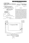
As previously set forth, the system interconnection panel
14 connects the components of the spa control system.
Referring to FIG. 3, the poWer 16 to the system intercon
nection panel 14 is supplied through usual poWer supply.
The Ground Fault Current Interrupter (GFCI) 64 provides
protection to the system interconnection panel 14 if an
25
imbalance of current ?oW occurs through the Door Interlock
63 betWeen the Input and the Output of the GFCI. The GFCI
64 prevents voltage and current from entering the system
control device With an 8-bit data bus 42. Its function is to
execute instructions, control processes, make logical deci
sions and compute values. The microcomputer 10 operates
after the device 64 has been triggered. After the poWer has
at a clock speed of typically tWo megahertZ and can make
thousands of calculations per second. The microcomputer 10
reads instructions from the memory, such as EPROM 44 and
passed through the GFCI 64, the PoWer Supply 66 converts
the 110 or 220 Volt AC into the loW voltage and loW poWer
required by some components of the system. The poWer
supply 66 also contains the backup battery or other device
(not separately shoWn) used to provide poWer to the RTC 34
then executes the appropriate actions.
The Eraseable Programmable Read Only Memory
(EPROM) 44 scores the instructions for the microcomputer
When the main poWer is turned off.
10 to execute. Once a program is created the ?nal softWare
35
The Opto-Isolators 60 receive signals from the spa control
is loaded into the EPROM 44. The EPROM 44 can be
panel
12 Which designate the operation of the proper output
modi?ed to add neW features, or additional EPROMs (not
device. The Opto-Isolators 60 isolate the loW voltage and
shoWn) can be connected to manage different functions and
current control system from the high voltage and high
applications. The Random Access Memory (RAM) 32 is a
current of the main poWer supply 16. These devices in
memory device Which stores temporary information While
the information is being processed by the microcomputer 10.
40
With the Zero volts crossing of the AC poWer 16 to sWitch
devices on/off When poWer is minimal to avoid stressing
devices. Connected to the Opto-Isolators 60 are the Triacs
62, Which are solid state devices used to drive high voltage
The RAM 32 only reads and Writes data, and can hold data
for future reference even after the main poWer 16 is turned
off. The RAM 32 stores data such as the number of hours on
the heater 26, the number of times that the temperature of the
spa exceeds the pre-selected temperature, and other infor
mation.
The Real Time Clock (RTC) 34 shoWs the proper time of
day Which is calculated after the time and date are initially
conjunction With Triacs 62 also provide synchroniZation
45
and high current output devices With alternating current.
Triacs 62 function as relays, except that Triacs 62 are
electronic devices that do not contain any moving parts.
Typically, the Triac 62 to a heating element may be rated at
forty amps maximum current, and the Triacs 62 to other
set. The microcomputer uses this information to schedule
events concerning the operation of the spa, such as When the
spa is turned on, When the Water is circulated, and other
output devices might typically be rated at tWenty-?ve amps.
Connected to the Triacs 62 is a ?eld connection board 70
events. The RTC 34 is backed With a battery or similar
Which mechanically permits the connection and disconnec
device (not shoWn) so that it maintains the accurate time
When the main poWer supply is turned off.
tion of ?eld devices such as a pump motor 24, bloWer motor
28, heater core 26, or a spa light 72.
The output devices are connected to the ?eld connection
The display interface 38 is responsible for driving and
updating the display device 40. When the microcomputer 10
sends information to this block 38 it is decoded and dis
played on the screen 46.
The display screen 46 is typically a vacuum-?uorescent
type Which has a blue-green color. The display contains four
seven-segment characters, and colon. The Display Interface
38 represents circuitry Which drives and updates the display
device. Information from the microcomputer 10 is decoded
55
board 70 by connectors 71.
The Analog Input section 36 converts information from
various sensors 20, 21, 22 into digital information so that the
data can be read by the micrcomputer 10. The converter 36
translates the analog information into digital information
through, for example, dual slope integration Which permits
fast and accurate conversion. The accuracy of the A—D
section 36 typically is 8 bits or a resolution of 1 out of 256.
and displayed on the screen 46 by the means of the interface
The signals from external probes and sensors 20, 21, 22 are
38. The data remains on the screen 46 until the microcom 65 conditioned by amplifying, ?ltering, or conditioning the
signals 37 so that the A—D converter 36 can make an
puter 10 sends a neW message or the system is reset or
poWered off.
accurate conversion. The Signal Conditioning section 37
US 6,976,052 B2
5
6
also receives the signals from external probes 20, 21, 22 and
the system is poWered up. It performs system initialiZation,
ampli?es it to a level Where the A—D converter 36 can make
an accurate conversion. This section 37 also provides tran
sient and surge protection to reduce normal and common
enables the other events, and then calls the main program.
The timer interrupt occurs periodically and inputs that
require periodic polling are scanned. The poWer fail inter
rupt occurs When system poWer is failing. The primary
mode rejection noise.
FIG. 4 illustrates a functional block diagram of the
purpose of this handler is to save the current system oper
ating parameters Within the time remaining before poWer
softWare Which operates the microcomputer 10. The ?nal
softWare code is encrypted on the EPROM 44 for operating
the microcomputer 10. The main program 80 schedules the
operation of all other subprograms and performs general
fails completely. The function of certain subroutines is in
one embodiment of the system are described in detail beloW.
10
control, interrupt handling and the scheduling of tasks.
The keyboard monitor routine 82 scans the keyboard and
is triggered by the operation 6f any key. The key signal from
the digital input is then decoded, and the main program 80
15
is triggered to initiate a series of programed events. The
program ignores multiple key depressions and erroneous
entries and operates only upon the signal generated from a
Digital I/O initialiZation
Restore NOVRAM image (to restore previous system
con?guration)
Clear display
proper key entry. The display control program 84 converts
data from the EPROM 44 to readable messages Which can
The system initialiZation routine is invoked by poWerup
reset. This routine is responsible or initialiZation of all
devices and data structures. The tasks it performs are:
Clear all RAM
Turn of all control outputs
housekeeping chores, such as memory management, timer
20
InitialiZe the RTC. If the time Was lost, it is reset to 12:00
midnight.
be shoWn on the display 40. The display control 84 handles
the timing of the signals so that the display 40 performs in
InitialiZe keyboard scanner
an ef?cient and proper manner. The alarm control 86 moni
Test the NOVRAM image or validity. If the image is
tors the proper operation of the entire spa system. If the
system malfunctions or otherWise operates incorrectly as
Examples of malfunctions in the system that might occur are
the malfunction of the heater 26 and Whether the pH 22
invalid, create fallback image and post Warning
Test EPROM (program space) memory
Display 110/220 volt setting
Perform RTC update test (takes a couple seconds)
Enable timer and poWerfail interrupts
levels are Within an acceptable range. In the event of a 30
Jump to main program
25
measured by the input signals or data inferred from the input
signals, the alarm Will signal the malfunction to the panel 12.
The time interrupt handler responds to the periodic timer
malfunction, a signal Will be sent to the display controller 84
to display the alert signal aid to alert the spa user of the
malfunction.
interrupts. It scans I/O devices that require constant scan
The Analog Conversion Program 88 manipulates the
timer base than the one second resolution provided by the
real time clock. The operations this handler executes are:
converter circuitry 36 to read and convert analog input
signals from sensors to digital information. This program
also converts the digital information to engineering units for
the purposes of display and comparison.
The RTC control program 90 controls all interaction With
the Real Time Clock 34. The program is responsible for
loading data for future events.
The PID Control 92 constructions stands for proportional,
ning for system operation and provides a higher frequency
35
Save interrupted program’s context
Update high speed clock value for synchroniZation With
mam program
Scan keyboard
40
one second timer update
Read in one analog channel. Provide raW input correction
integral and derivative control. This program 92 performs
the closed loop control of temperature using the temperature
input 20, 21 as its variable to be controlled and the heating
elements 29 and the output to maintain control. The program
92 monitors the temperature 20, 21 of the Water and deter
mines When the heater 26 should be engaged. The program
issues a command Which activates the heater 26, and then
monitors the temperature 20, 21 to determine When the
heater 26 should be turned off. The program is unique in that
it also monitors the rate of decrease and the rate of increase
of the Water temperature so that the ?nal temperature of the
Water is not higher or loWer than the selected temperature
45
beyond the control supplied by derivative control. The spa
55
Return to the interrupted program
circuit Which monitors poWer loss on system input poWer.
When a decline is detected, an interrupt is posted to the
eters as Well as user settings)
Turn off all spa controls
The output, control program 94 issues commands to the
output components to turn on the Triacs 62 for control of the
60
approximately one second, the poWerup reset handler is
called.
The main program 104 performs the bulk of the opera
pH input 22 and converts this data to standard pH units of
Three events are handled by the system. Reset occurs When
Display “Fail”
Monitor poWerfail interrupt for poWer restoration (broWn
out). If poWerfail is cleared and remains cleared for
raW digital data received from the A—D converter 36 on the
FIG. 6 provides an overvieW of the program organiZation.
microcomputer. The poWerfail handler is invoked When this
interrupt is posted. It is responsible for saving the current
system con?guration and for shutting the system doWn in an
orderly fashion. The tasks it performs are:
Mask all interrupts
Save system con?guration (this includes operating param
degree Fahrenheit With the heating and monitoring elements.
measure.
and calculate engineering units (temperature values are
curve-?tted, and pH values are temperature corrected)
Restore interrupted program’s context
The poWerfail interrupt is furnished by a level-monitoring
control system can achieve an accuracy of plus or minus one
pump 24, heater 26, bloWer 28, lights 30 and other compo
nents. The input scanning program 96 monitors devices such
as push buttons and sWitches. The pH algorithm 98 converts
Poll real time clock and if seconds have changed, provide
65
tions performed by the system controller. It synchroniZes
With the timer interrupt so that a reasonably constant time
base be is used. A state machine is maintained to determine
US 6,976,052 B2
8
7
hoW keyboard inputs are to be interpreted and What is to be
displayed. The following tasks are performed by the main
Set the hour of the start time
Set the minute of the start time
program:
Set the duration of the interval. This value changes in
On initial (poWerup) entry, pause to alloW timer interrupt
handler time to build valid input values
increments of ten minutes and can be set from Zero to
eight hours.
Synchronize With timer interrupt. While Waiting for timer,
The time of day is set in tWo steps. First the hour is set,
drive buZZer output.
Update the general timer used by state handlers for
timeouts
Run ?asher manager
then the minute. Hours are displayed With an “A” or “P” for
am and pm indication.
10
Get current keyboard inputs
If any keyboard inputs are available, post buZZer output
request and reset the “system unattended” timer
Handle keyboard inputs for maintenance mode entry/exit
Call control manager keyboard input handle
Call current state manager’s keyboard handler routine
Handle remaining function keyboard inputs to drive state
heating Whenever the temperature drops beloW the loW
15
changes
Go to current state’s display handler
Call control manager to drive system controls
20
Go back to the timer synchroniZation step (step 2)
Operator settings can be controlled by keys on the system
keyboard Which are used to select modes that alloW the
operator to change settings that control system operations.
These are grouped at the right side of the keyboard. They
This scheduled heating function alloWs the user to de?ne
the hysteresis that is to be used When the spa is unattended.
It also alloWs a “start time” to be de?ned. The spa Will begin
25
are:
temperature setting or the time matches the start time. With
an appropriate temperature envelope, this Will alloW the spa
to heat once a day While unattended. The folloWing steps are
used to de?ne this function:
Set the hour of the start time
Set the minute of the start time
Set the high limit of the temperature envelope
Set the loW limit of the temperature envelope
Enable/disable this function
The idle mode is used When none of the operator setting
functions are active. At this time, the display scrolls through
a sequence of displays that display the systems current state.
The time, temperature, pH and error indications may be
cycled continuously.
Spa temperature
Spa ready
Concerning operator controls, some fo the systems con
Filter maintenance
30
Time of day
Scheduled heating
trol outputs are directly controlled by the operator through
alternate action inputs on the keypad. These are the light, jet
and turbo keys. The control, manager’s keyboard handler
All of these functions adhere to a consistent operator
accepts these keyboard inputs and changes the current
interface scheme. When the function key is pressed, the LED
output values. These changes are then re?ected on the
LED’s neXt to the keys. The LEDs are lit When the corre
sponding control is on.
Maintenance mode is a special state that is reached by
52 neXt to the key 50 is lit. The LED remains lit until all
steps have been completed or another function has been
selected. While setting a value, the value is displayed on the
screen 46 and is ?ashed. The arroW keys are used to change
35
turning the maintenance sWitch to its “on” position. When
the displayed value and the function key is pressed to
proceed to the neXt step in the setting. While changes are
being made, the display 4Q stops ?ashing to avoid changes
the maintenance mode is active, all controls are turned off
and the functions of the keys are rede?ned. When none of
40
occurring While the display is in the off state. Once changes
have stopped, the display resumes ?ashing. Changes are
played. The arroW keys alternately light all LEDs and
honored as they are made and the operator can change one
step of a function Without affecting the remaining steps. The
current setting can be revieWed by pressing the appropriate
function key repeatably. When a function that has been
the keys are active, “test” is displayed. When each key is
pressed, its corresponding LED is lit and a value is dis
45
display segments and the turn all LEDs an segments off. The
folloWing is a map of the keys and the values displayed in
maintenance mode:
de?ned by the operator is currently being executed, the LED
neXt to the corresponding button blinks.
The spa temperature key is used to de?ne the temperature
setpoint. This function has only one step that alloWs the
setpoint to be changed. Pressing the set temperature key
again eXits the mode.
The spa ready key is used to de?ne When the spa is to be
at a particular temperature. The folloWing eXample Would
SCHEDULED HEAT
SPA READY
FILTER
TIME
pH input
spa temperature input
heater temperature input
TEMPERTURE
JET
TURBO
heater run accumulator
pump run accumulator
turbo run accumulator
overtemp time accumulator
cause the system to bring the spa temperature to 102 degrees
at 6:30 pm.
55
Accumulated time values are displayed in thousands of
hours. A decimal point is placed to autorange the displayed
value.
Example
Set the hour of the ready time
Set the minute of the ready time
Set the temperature to be achieved
Enable/disable this function
06: P
06:30
102
On
60
System calibrations are accessed by pressing the light key
While in maintenance mode. When the light key is pressed,
a series of options are displayed. To select a step, or continue
it, an arroW key is pressed. To get the neXt selection or return
to the “test” display, the light key is pressed. The options
available are:
The ?lter maintenance key is used to de?ne an interval
during Which the loW speed pump is to be run to ?lter the spa
Water. It has the folloWing steps:
65
CALO Calibrate analog channel 0 (spa temperature 21).
This is a tWo point (32 and 104 degree) calibration for
offset and gain correction.
US 6,976,052 B2
10
CAL1 Calibrate analog channel 1 (heater temperature 20).
The KBCHERR routine is called When the calibration is
in the high error state. It handles the keyboard input and
This is identical to CALO.
CAL2 Calibrate analog channel 2 (pH input. This is a one
alloWs the user to abort the sequence or return to the high
point (0 volts) calibration for offset correction.
value input state.
The DSPCHERR routine is called to display the message
“HnzEr” When the high calibration step is in error. “n” is
CPU Display cpu RAM contents.
nov Display NOVRAM contents.
either 0 or 1.
rvX.y The softWare revision is “X.y”
The following describes the modules that make up the
The KBCDONE routine is called to handle keyboard
inputs When the calibration is complete. It alloWs the user to
system controller and further describes the algorithms they
contain:
10
The module anlgin-routine anlgin routine controls the
input of a speci?ed analog input channel. The operations it
“done” message until the user acknoWledges it.
The DSPCDONE routine is called When the calibration
has reached a successful conclusion. It displays the message
“done”.
performs are:
output channel number
read input value
return to the idle maintenance mode state. It acts to hold the
15
GETRAW is a routine local to the calibration module to
The module BCDNEG routine is called to negate a BCD
value.
The module BINBCD routine is called to convert a binary
fetch the appropriate raW input from the raW input table.
The KBCPH routine is called When “CAL2” is displayed.
value to a BCD value.
“light” menu or to calibrate the pH input.
The KBCPHI routine is called to handle keyboard inputs
When calibrating the pH input. It alloWs the use to abort the
operation, or to accept the current input. If the current input
has an error of less than 32, the offset is stored and the
calibration goes to the “done” state. If the error is too large,
the system goes into the pH error state.
The DSPCPI routine is called to display the current raW
It alloWs the user to choose to move to the neXt item in th
The buZZkey routine is called to determine if the key
closure should result in the buZZer beeping. “Positive” key
values result in the buZZer ?ag being set for “buZZer”.
The buZZer routine is called to drive the buZZer if a key
Was pressed. The buZZer interval is decremented until it is
Zero and the buZZer stops.
The buZZoff routine is called to cancel the keyboard
buZZer output in special cases When the state handler Wishes
25
pH input during pH calibration. It forms a message of the
to block certain keys from being acknoWledged.
form “PHzxx” Where XX is the current raW input.
The KBCALO routine is called to handle keyboard inputs
The KBCPHE routine is called to handle keyboard inputs
While displaying “CALO”. It alloWs the user to move on to
When the pH calibration value has too large an error. It
alloWs the user to abort the operation or to retry the
CAL1 or to select to calibrate analog channel 0.
The KBCAL1 routine is called to handle keyboard inputs
calibration.
While displaying “CALI”. It alloWs the user to move on to
CAL2 or to select to calibrate analog channel 1.
The DSPCPE routine is called to display the error mes
sage “HnzEr” When the calibration value has too large of an
The DSPCALO, DSPCAL1, DSPCPH routines display
the “CALn.” message.
35 error.
The KBCLOW routine handles keyboard inputs While
scanning the loW (32 degree) value during calibration or
The module control-routine CTLPOLL routine is called
by he main program to perform the actual output controls.
The folloWing tasks are performed:
Set Ready—if the set ready function is enabled, this
section decides if the set ready function is to perform any
actions. If the current time marches the ready time, the set
channels 0 and 1. The user can select to abort or continue.
If the choice is to continue and the raW input value is in the
range 1 . . . 31, then the value is accepted and calibration
continues to the high step. OtherWise, the loW error state is
entered.
The DSPCLOW routine is called to display the raW value
ready temperature is copied to the spa temperature setpoint,
the spa is marked “attended” and the set ready function is
While Waiting or the loW (32 degree) input value. It builds a
disabled to prevent further actions.
display of the form “Lnzxx” Where n is 0 or 1 and XX is the
45
For the Set Ready, as Well as for Normal Temperature
raW input value.
The KBCLERR routine is called When the calibration is
Control discussed infra, the time required to get from the
in the loW error state. It alloWs the user to choose to abort
current temperature to the desired temperature is calculated
and With a ?fteen minute hysteresis, the decision is made
or retry the input of the calibration value.
The DSPCLERR routine is called to display the loW
Whether to turn the function on, or to turn it off. If the
function is to be on, a request is posted to the heater to run.
calibration error message of the form “LxzEr” Where X is 0
System Attended—system attendance is checked and if
the system is unattended, the high speed jet and the turbo
or 1.
The KBCHI routine is called to handle keyboard inputs
While the temperature calibration is in the high (104 degree)
controls are turned off. The system is marked attended if a
input state. It alloWs the user to abort or accept the current
key has been pressed Within the last 30 minutes.
Scheduled Heating—if the scheduled heating function is
enabled, this section decides if this feature should perform
any actions. If the system is attended, control is passed to
neXt section, normal setpoint control. If the function is off,
the temperature is compared to the loW setting and the time
is compared to the time setting. If appropriate, the function
is requested, but control is still passed to the “on” section to
setting If the current setting is in the range 163 . . . 195, the 55
value is accepted. In conjunction With the previously
obtained loW value, a pair of values, m and b, are calculated
such that With raW value r, m*r+b Will result in a corrected
value at the tWo calibration points. These tWo values are
stored in NOVRAM and used from this point onWard in
temperature calculations for this channel. The system then
proceeds to the “done” state. If the input value is not in the
correct range, the system proceeds to the high error state.
The DSPCHI routine is called to display the raW input
While in the high (104 degree) calibration step. It builds a
message of the form “Lnzxx” Where n is 0 or 1 and XX is the
raW value.
alloW it to override the time startup. If the function is on, the
temperature is compared to the high setting and turned off if
the setting has been reached. The neXt section, normal
65
setpoint control, is then skipped.
Normal Temperature Control—this function is executed if
the system is attended or if the scheduled heating function is