1
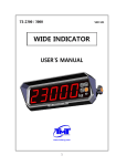
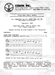
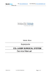
RADIO TRANSMISSION
MODULE
SM7
USER’S MANUAL
1
2
RADIO TRANSMISSION MODULE
SM7
USER’S MANUAL
CONTENTS
1. APPLICATION ................................................................................ 5
2. SET OF THE SM7 MODULE.......................................................... 6
3. INSTALLATION ............................................................................. 6
3.1. Module Mounting .................................................................... 7
3.2. SM7 Electrical Connections ................................................... 8
3.3. Way of Connection with Devices .......................................... 10
3.4. Requirements for Outlet Connections ...................................11
3.5. Examples of Heat, Energy
and 3000 Configurations to Co-operate
with SM7 Module ...................................................................11
4. MODULE PRINCIPLE OF OPERATION ...................................... 12
4.1. First Start of the SM7 Module and PC Computer ................. 14
4.1.1. Installation of the Configuration Program on PC ....... 14
4.1.2. Configuration Procedure of the SM7 Module ............ 14
5. TECHNICAL DATA....................................................................... 20
6. SM7 ORDER CODES................................................................... 22
7. MAINTENANCE AND WARRANTY ............................................. 22
3
4
1. APPLICATION
The SM7 radio transmission module is a device destined for data transmission by
radio in the non-licensed 433 MHz or 868 MHz band with output power from - 20
to 10 dBm in one of ten accessible radio channels. The data baud rate in the radio
channel changes in the range: 4800.....76800 bit/s, however in the serial port, it is
possible to set up the baud rate in the range: 4800.....115200 bits/s.
These changes are carried out by means of the annexed SM7Config.exe configuration program.
The offered module is become completed with a stub antenna equipped with a
connector of SMA type, SMA/SMA angle adapter and a concentric cable destined
to locate the antenna in any place.
The SM7 radio transmission module finds application among other things in power
engineering, automatics - for monitoring data of the manufacturing process and in
many other applications requiring data transmission.
The SM7 module enables the data readout from devices equipped with serial interfaces (RS-485 or RS-232). The data exchange with the master device is carried
out in the radio circuit with 433 MHz or 868 MHz frequency.
The SM7 module enables the work in one of ten radio channels, in two different
types of data encoding, Manchester or NRZ.
The addressing radio circuit has been applied in the module, what gives the possibility
of grouping modules working on the same radio channel.
Exemplary applications of the SM7 module are presented on the fig. 1.
SM1
module
PC operation station
SM7
SM7
Pressure
transducer
P18
temperature
and humidity
transducer
Fig.1. Exemplary monitoring of temperature, humidity and pressure
5
2. SET of the SM7 MODULE
The set of the data acquisition module is composed of:
l SM7 module .................................................................................. 1 pc,
l stub antenna .................................................................................. 1 pc,
l SMA/SMA angle adapter ............................................................... 1 pc,
l antenna cable ................................................................................ 1 pc,
l plug with screw terminals of BU1005 type ...................................2 pcs,
l plug with screw terminals of BU0204 type ...................................2 pcs,
l SM7 user’s manual........................................................................ 1 pc,
l warranty card ................................................................................. 1 pc,
l mini CD with software ................................................................... 1 pc.
When unpacking the instrument, please check whether the type and execution code
on the data plate correspond to the order.
3. INSTALLATION and SAFETY REQUIREMENTS
Symbols located in this service manual mean:
WARNING!
Warning of potential, hazardous situations.
Especially important. One must acquaint with this before connecting
the instrument. The non-observance of notices marked by these
symbols can occasion severe injuries of the personnel and the
damage of the instrument!
CAUTION!
Designates a general useful note. If you observe it, handling of
the meter is made easier. One must take note of this, when the
instrument is working inconsistently to the expectations. Possible
consequences if disregarded !
In the security scope the instrument meets the requirements of the EN 61010 -1
standard.
Remarks concerning the operator safety:
1. General
l The instrument is destined to be mounted on a 35 mm rail acc. to the fig. 2.
l Non-authorized removal of the required housing, inappropriate use, incorrect
installation or operation create the risk of injury to personnel or damage to
6
equipment. For more detailed information, please study the present user’s
manual.
l All operations concerning transport, installation, and commissioning as well
as maintenance must be carried out by qualified, skilled personnel and
national regulations for the prevention of accidents must be observed.
l According to this basic safety information, qualified, skilled personnel are
persons who are familiar with the installation, assembly, commissioning, and
operation of the product and who have qualifications necessary for their
occupation.
2. Transport, storage
Please observe the notes on transport, storage and appropriate handling.
Observe the climatic conditions given in Technical Data.
3. Installation
l The meter must be installed according to the regulation and instructions given
in this user’s manual.
l Ensure proper handling and avoid mechanical stress.
l Do not bend any components and do not change any insulation distances.
l Do not touch any electronic components and contacts.
l Instruments may contain electrostatically sensitive components, which can
easily be damaged by inappropriate handling.
l Do not damage or destroy any electrical components since this might
endanger your health!
4. Electrical connection
l Before switching the instrument on, one must check the correctness of
connection to the network.
l In case of the protection terminal connection with a separate lead one must
remember to connect it before the connection of the instrument to the mains.
l When working on live instruments, the applicable national regulations for the
prevention of accidents must be observed.
l The electrical installation must be carried out according to the appropriate
regulations (cable cross-sections, fuses, PE connection). Additional
information can be obtained from the user’s manual.
l The documentation contains information about installation in compliance with
EMC (shielding, grounding, filters and cables). These notes must be observed
for all CE-marked products.
l The manufacturer of the measuring system or installed devices is responsible
for the compliance with the required limit values demanded by the EMC
legislation.
7
5. Operation
l Measuring systems including SM7 modules must be equipped with protection
devices according to the corresponding standard and regulations for
prevention of accidents.
l After the instrument has been disconnected from the supply voltage, live
components and power connections must not be touched immediately
because capacitors can be charged.
l The housing must be closed during operation.
6. Maintenance and servicing
Please observe the manufacturer’s documentation.
Read all product-specific safety and application notes in this user’s manual.
l Before taking the meter housing out, one must turn the supply off.
l The removal of the instrument housing during the warranty contract period
may cause its cancellation.
3.1. Module mounting
The module is fixed on a 35 mm rail acc. to the fig.2.
Fig.2. Overall dimensions and module fixing way
8
3.2. SM7 Electrical Connections
The supply and external signals must be connected acc. to the fig. 3 and the
table 1 in which the assignment of particular outlets of the SM7 module has been
described.
a) for 85...253 V a.c./d.c. and 20...50 V a.c./d.c. supplies
b) for 7....35 V d.c. supply
Fig. 3. Description of SM7 outlets
9
Table 1
Description of SM7 outlets
Terminal No
1
2
3
4
5
6
7
8
9
10
11
12
13
14
15
16
17
18
Terminal description
TxD RS-232 line
RxD RS-232 line
GND RS-232 line
(not used)
(not used)
(not used)
+5 V 25 mA line
GND RS-485 line
A RS-485 line
B RS-485 line
Supply line (+ for d.c. current supply)
Supply line (- for d.c. current supply)
Functional ground line (d.c. supplied)
(not used)
(not used)
(not used)
(not used)
(not used)
Table 2
Description of SM7 module diodes
Description
Markings
RxD
(red)
TxD
(yellow)
RxRF
(red)
TxRF
(green)
10
Data receipt from the serial port
Data transmission to the serial port
Receipt of radio data
Transmission of radio data
3.3. Way of Connection with Devices
The way of SM7 module connection to RS-232 or RS-485 interfaces
are presented on fig. 4 and 5.
Fig.4 Connection way of SM7 module to the RS-232 bus
Fig.5 Connection way of SM7 module to the RS-485 bus
11
Caution:
Considering electromagnetic interference, one must apply shielded
wires to connect RS-485 interface signals. The shield must be connected to the earth terminal in a single point. The supply should be
connected to the earth terminal in a single point. The supply should
be connected by a two-wire cable, with an appropriate diameter of
wires assuring its protection by means of an installation cut-out.
3.4. Requirements for Outlet Connections
Practically, different interference sources occurring, influence on the module in a
continuous or impulse way from the supply network side (in consequence of the
other device operations). The level of this interference should be reduced to a value
lower than the module immunity threshold, first of all through the appropriate module
installation in the object.
In order to obtain a full immunity of the module against electromagnetic interference in an environment with an unknown interference
level, it is recommended to observe following principles:
l Do not apply the module from the network in the proximity of devices
generating high impulse interference,
l Apply network filters for the group of modules servicing the same object,
l Apply the general principles, that wires (group of wires) leading different
signals should be led farther away to one another (not less than 50 cm),
and crossings of such group of wires made at an 90°C angle.
3.5. Example of Heat, Energy and 3000 Configuration to co-operate
with the SM7 Module
Heat and Lumel 3000 systems communicate with industrial devices by means of
COM serial ports. The SM7 module does not require the installation of whatever
programmable logic controller.
In case when there is not enough of serial ports in the computer, one can increase
this number installing a PD10 or PD12 USB converter on the bus, what extends
computer resources with additional COM ports. After installing additional COM
serial ports, one can refer to them in offered systems. Then, one must introduce
or change supervisory calls to the added communication ports, in new or existing
applications or system configurations.
Energy softwares in older version then 2.5, service maximally 4 serial ports, and
they must be installed as COM 1... 4 in such systems.
12
4. SM7 MODULES PRINCIPLE OF OPERATION
The SM7 radio transmission module enables the radio communication of devices
equipped with an RS-232 or RS-485 serial port.
The maximal baud rate in the radio channel is 76800 bit/s. This rate can be changed
in the range: 4800....76800 bit/s.
The communication with RS-232 or RS-485 interfaces can be carried out with baud
rates from 4800... 115200 bit/s. The radio transmission is performed maximally in
the shape of 226 byte packages, from which 256 bytes are data received from the
serial port, and remaining are applied for the need of package forming.
The data transmission is carried out in the following way: data bits are received
from the serial port and they are switched over to the sending buffer. If the sending
buffer will be filled up or if a suitable time is elapsed („time out”), data are placed
in a frame automatically provided with an appropriate heading and transmitted by
the radio channel.
The heading is built from the sequence of six unique bytes, allowing the receiving
devices to identify streams of radio waves as frames with data, Apart from the cited
sequence of bytes, the group address of the module transmitting data is encoded
in the frame heading.
The insertion of this address in the frame increases the data safety and allows to create several groups of modules working independently on the same radio channel.
The reception of radio data resolves itself into the detection of the correct data
frame. After receiving the correct frame, the grouped address encoded in the frame
is checked. If the address is identical as the module address, which the frame have
received, then received data are directed to the serial port.
The current operating conditions of the module are signalled by lighting diodes:
Red RxD diode and yellow TxD diode signal the data flow through the serial port,
however the red RxRF and green TxRF signal the data flow through the radio
channel. If during the transmission both the red RxRF diode and the green TxRF
diode are lighted, that means that the reception buffer was overfilled by a to high
number of data from the serial port (more than 256 characters) and their transmission
through the radio line was cancelled. RxRF and TxRF diodes are also lighted after
introducing the module in the configuration state.
The transmission between the master device and the module can run faster than
in the radio circuit because of the RS-485 port application to control the data flow,
the CTS signal which informs the master device if the module is ready to the
data reception, has not been applied. In this connexion, for the correct module
operation, it is recommended to apply the same baud rates of the serial port and
the radio circuit.
The module is configured by the manufacturer to work on the serial port with a 9600
bit/s baud rate in the 8N2 mode, and on the radio circuit with the 9600 bit/s baud rate,
13
with the Manchester encoding and the transmitter power equal + 10 dBm, however
all parameters can be changed depending on requirements.
The configuration is carried out by means of the SM7config.exe configuration program. The configuration program takes advantage of the RS-232 serial port and
exchanges data with the SM7 module using its own communication protocol.
One must remember, that the module configuration program works with following
serial port settings:
- baud rate: 9600 bit/s
- transmission mode: 8N2
To switch the SM7 module into the configuration mode, one must press for three
seconds during the module operation, the button being at the bottom of the housing.
The button location is presented on the fig.6.
After pressing the button, the SM7 module breaks the normal operation, switches
over to the configuration mode and adapts the setting of its serial port to settings
of the configuration program, i.e. 9600, 8N2
After the configuration change, one must turn the module supply off, and next switch
it on again. The module will start to the normal work with new settings.
Fig.6. Location of the configuration button
14
4.1. First Start of the SM7 Module
At the first start, the SM7 module requires settings of following indispensable
information: group address, radio channel, transmitter power, type and radio baud
rate. Apart of this, it is necessary to set parameters of the serial port: baud rate and
transmitter mode. The „SM7config.exe”) program added to the set, allows the user
to configure in an easy way the SM7 module setting.
4.1.1. Installation of the Configuration on PC
The installation consists in copying of the „SM7config.exe” program from the added
CD disk to the set, into the catalogue assigned by the user on the computer hard
disk. The program can be also started directly from the CD disk.
4.1.2. Configuration Procedure of the SM7 Module
In order to configure the SM7 module, one must connect it to the computer serial
port:
RS-232 (outlet description according to the fig. 3.), next, turn the module supply
on, press the module configuration button and hold it during ca 1 sec. Then, RxRF
and TxRF diodes are lighting till the moment of the supply turning off. After starting the „SM7Config.exe” program, one can choose in the „Port COM:” field, the
number of the COM port which the SM7 module is connected to. After pressing the
„Connect” button, the configuration program establishes the connection with the
SM7 module, and the message: „Connected with the COM port” appears in the
communication window.
In case of access lack to the COM port, the information about the lack of connection with the COM port will be displayed in the message window. After the correct
connection established with the SM7 module, the configuration program displays
the information about the current module configuration.
The change of the module configuration consists in making the choice in appropriate
fields in the program window.
Following options are accessible:
- Options of the serial port.
- serial baud rate (4800....115.200 bit/s),
- serial transmission mode (8N1, 8N2, 8E1, 8O1, 7E1, 7O1).
- Options of the radio port:
- setting of the radio circuit ( group address, radio channel number),
- transmission type (baud rate: 4800....76800 bit/s and encoding type: NRZ
or Manchester),
- transmission power ( from - 20 dBm to 10 dBm).
15
NOTE: One must remember that the optimal module work is reached at the
setting of similar baud rate for both interfaces, i.e. the serial port and
the radio circuit. For other settings, the occurrence of erroneous data
transmission states is possible.
The button „Restore manufacturer settings” allows to set up manufacturer settings
in the module.
Each change of settings is registered in the message window of SM7Config.exe
program and transmitted to the SM7 module.
In case of correctly or erroneously carried out operation of the setting change, an
appropriate message will be displayed in the message window
After carrying out changes, one must disconnect the transmission choosing the
„Disconnect” button. The disconnection of the transmission and the release of the
COM port by SM7Config.exe will follow. Set parameters of the module configuration
will be operative after turning the module supply off for ca 3 sec. and it renewed
turning on.
Fig. 7. View of the SM7Conf.exe configuration application
16
5. TECHNICAL DATA
Port 1:
– RS-232 interface
- data format
- baud rate
8N1, 8N2, 8E1, 8O1, 7E1, 7O1
2400... 115200 bit/s
Port 2:
– RS-485 interface
- format danych
- prêdkoœæ transmisji
8N1, 8N2, 8E1, 8O1, 7E1, 7O1
4800... 115200 bit/s
Radio circuit:
- carrier frequency
- power
- receiver sensivity
- baud rate
- encoding type
- transmission range in direct line
- number of channels
- antenna output
433, 868 MHz
-20, -15, -10, -5, 0, 5;
(10 dBm only for 433 MHz)
-110 dBm
4800, 9600, 19200, 38400, 76800 bit/s
NRZ, Manchester
300 m
10
50 W SMA
Time of availability obtainment
since the supply connection
2s
Module input power
£ 2.5 VA
Rated operating conditions:
- supply voltage
- ambient temperature
- relative air humidity
- service position
7... 35 V d.c.; 20... 24...50 V a.c./d.c.
85...230... 253 V a.c./d.c.
0...23...45°C
< 95% (condensation inadmissible)
any
Storage and handling conditions:
- ambient temperature
- relative air humidity
-20... 70°C
< 95% (condensation inadmissible)
Ensured protection grade:
- from the housing side
- from the terminal side
IP 20
IP 20
Overall dimensions
45 ´ 120 ´ 100 mm
Weight
0.5 kg
17
Housing
Electromagnetic compatibility:
- noise immunity
- resistance against supply decay
- noise emissions
for 35 mm rail mounting,
acc. EN 60715
acc. EN 61000-6-2
acc. EN 61000-6-2
acc. EN 61000-6-4
Safety requirements acc. to EN 61010-1:
- installation category
III
- pollution grade
2
- maximal phase-to-earth work voltage:
- for supply circuit
50 V
- for other circuits
50 V
SM7 ORDER CODES
Radio transmission module SM7
X
X
X
Supply voltage:
85...230...253 V a.c./d.c............................................................1
20...24...50 V a.c./d.c................................................................2
7...35 V d.c. ..............................................................................3
on order* .................................................................................. X
Radio carrier frequency:
433 MHz ..........................................................................................1
868 MHz ..........................................................................................2
Acceptance tests:
wthout additional tests ............................................................................ 8
with an extra quality inspection certificate .............................................. 7
acc.to user’s agreement* ........................................................................ X
* The manufacturer will establish the code number.
Coding example:
The SM7 1 2 7 code number means:
SM7 - Radio transmission module
1 - supply voltage: 85...230...253 V a.c./d.c.
2 - radio carrier frequency: 868 MHz
7 - with an extra quality inspection certificate
18
7. MAINTENANCE AND WARRANTY
The SM7 modul does not require any periodical maintenance.
In case of some incorrect operations:
1. After the dispatch date and within the period stated in the warranty card
One should return the instrument to the Quality Inspection Dept.
If the instrument has been used in compliance with the user’s manual, the manufacturer warrants to repair it free of charge. The disassembling of the housing
causes the cancellation of the granted warranty.
2. After the warranty period:
One should send the instrument to repair it in a authorized service workshop. Spare parts are available for the period of five years from the date of purchase.
The manufacturer reserves the right to make changes in design and
specifications of any products as engineering advances or necessity
requires.
19
SM7-07.A