1
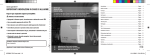
AirScan iR
TM
Manning
AirScan iR
TM
Refrigerant Sensor for
Commercial Applications
Refrigerant Sensor for
Instruction and
Industrial
Applications
Installation Manual
Rev A
Instruction and Installation Manual
Rev A
MOUNT ENCLOSURE THIS END UP. DO NOT BLOCK PERFORATED VENT HOLES.
Manning AirScan
Honeywell Analytics
11511 West 83rd Terrace
Lenexa, Kansas 66214
[email protected]
Manning
AirScan-iR or
Refrigerant
Sensor 19100 www.gasalarm.com
AirScan-iR-ind 05/2006 REVA Copyright © 2006 Manning Systems, Inc. All Rights Reserved.
800.444.9935
913.894.1185
19100AirScan-iR-ind 5/2006 REVA
913.894.1296 fax
9138941296fax
19072 ECF9NH3 4/2006 REVE
1
Contents
Serial number:
Section
Title
1 Sensor Description
System Specifications and Sensor Specifications
4
2 Installation
A
Locating the Sensor
TM
Figure 1: Mounting Dimensions for the AirScan iR
5
5
B
Wiring
TM
Figure 2: Wiring Diagram for AirScan iR
6
6
A
Start-up Procedure
Figure 3: Required LED Status at Start-up
7
7
B
Pushbutton Operation, LED Indicators, Adjustment Pots and Test Points
Figure 4: Board Component Layout
Figure 5: LED Layout
LED Indicators and Blink Sequence
Figure 6: LED Blink Sequence
Figure 7: LED Indicator Summary
Normal Run Modes
4/20 mA Loop Test Mode
Calibration Mode
Fault Indicator Error Sequences
8
8
8
9
9
10
10
10
10
11
C
Modes of Operation
Normal Run Modes
4/20 mA Loop Modes
Calibration / Programming Modes
12
12
13
14
D
Calibration
Figure 8: Board Component Layout
4/20 mA Output Calibration
Zero Calibration
Figure 9: Board Component Layout
Span Calibration
15
15
17
17
18
18
E
Diagnostic Procedures
Simple Zero Test
4/20 mA Output Loop Integrity Check
19
19
19
F
Troubleshooting
Electrical Interference
TM
Figure 10: Troubleshooting the AirScan iR
Sensor On-Board Diagnostic System
Error on 4/20 mA Output
Sensor Output at 0 mA
Sensor Output at .5 mA
Gas Concentration Indicated with No Refrigerant Present
IR Source Failure
21
21
21
21
22
22
22
22
22
3 Operation
Page
4 Maintenance
23
5 Replacement Parts
23
6 Limited Warranty
24
Manning AirScan-iR Refrigerant Sensor 19100 AirScan-iR-ind 05/2006 REVA Copyright © 2006 Manning Systems, Inc. All Rights Reserved.
2
Introduction
This manual has been prepared to help in the use and installation of the Manning
AirScanTMiR (Infrared Refrigerants) Sensor. This manual will convey the operating principles
of the sensor, ensure proper installation, and demonstrate start-up and routine
maintenance procedures.
This manual must be carefully followed by all individuals who have or will
have the responsibility for using or servicing the Manning AirScanTMiR Sensor.
Warranties made by Honeywell Analytics with respect to this equipment will be voided if
the equipment is not used and serviced in accordance with the instructions in this manual.
If in doubt about a procedure, please contact Honeywell Analytics before proceeding.
Manning AirScan-iR Refrigerant Sensor 19100 AirScan-iR-ind 05/2006 REVA Copyright © 2006 Manning Systems, Inc. All Rights Reserved.
3
1
Sensor Description
Gas detection by the infrared method is based on the
principle that most gases absorb infrared energy at a
characteristic frequency. In this instrument, a broad
band infrared source emits energy which is then bandpass filtered to produce a narrow range of frequencies
characteristic of the refrigerants’ (CFC/HCFC/HFC)
absorption spectra. Any refrigerant in the gas sample
cell selectively absorbs energy reaching the detector.
This reduction in energy is detected, amplified and sent
to the signal processing portion of the system.
TM
The Manning AirScan iR Sensor line is a three-wire,
4/20 mA sensor for two bands of refrigerants available
in a range of 0—3,000 ppm, but can be adjusted for
lower ranges, if required. The low-band or R-404a
infrared sensor reacts to R-123, R-134a, R-404a and
TM
R-507. The high-band or R-22 AirScan iR sensor
reacts to R-22.
Its solid, high-mass metal bench provides structural and
thermal stability, greater immunity to vibration, as well as
superior EMI/RFI shielding of the detector and source.
Internal compensation for environmental changes
allows the sensor to automatically adapt to fluctuating
temperature and humidity conditions. The unit exhibits
extremely high reliability with no moving parts.
TM
Cable Recommendation: Three conductor, stranded,
shielded cable with drain wire, all enclosed in a vinyl jacket.
For cable runs up to 200 feet use, #18 AWG (Belden #8770
or equivalent). For cable runs up to 1,000 feet, use #16 AWG
(Belden #8618 or equivalent). If sensor is SUPER HEAT
equipped (—15° F and below), contact Honeywell Analytics
for cable recommendations.
TM
NOTE: The standard AirScan iR is for use in nonclassified areas only.
Sensor Specifications
Type: CFC/HCFC/HFC selective infrared gas sensor/
TM
transmitter AirScan iR
Method of Detection: Dual channel infrared energy
absorption (N.D.I.R. Non-dispersive Infrared)
Gases Monitored: Low-Band (R-404a, R-507,
R-134a, and R-123), High-Band (R-22)
Range Available: 0—3,000 ppm (can be rescaled to
0—1,000 ppm, or 0—500 ppm if required)
SensorCheckTM Features: Dual channel functionality test,
source strength evaluation, incoming voltage monitor, IR
source integrity check, operating temperature monitor,
“zero” down drift monitor, and internal circuitry check.
Every two seconds SensorCheck technology
TM
monitors the AirScan iR source and ensures that the
dual channels are functioning properly. A notification
signal will be transmitted if any of several performance
parameters is not met.
Accuracy: ± 3% of full scale
Monitoring equipment must be configured to indicate
a fault if the signal is less than 1.5 mA. All signals over
20 mA must be considered a high gas concentration.
Operating Humidity: 0—100% RH (condensing).
ATMOS equipped® enviro-adaptive technology option
required for condensing conditions or refrigerated areas.
Manning infrared sensors are normally long-lived
(5 years plus), unless physically damaged or wetted
with water or other liquid.
Operating Temperatures: —50° F to +140° F. ATMOS
System Specifications
Electrical Power: 24 Volts DC regulated, 1.0 amp.
Output: Linear 4/20 mA output into a load resistor of
500 ohms maximum
Cable Length to Sensor: 1,000 feet maximum
Unit Enclosure: NEMA 4, gasketed, molded fiberglass
reinforced polyester. Non-painted, non-rusting
construction appropriate for food areas. UL 508 listed,
CSA certified for use with industrial control equipment.
Repeatability: ± 1% of full scale
Cross Sensitivity: Not affected by moisture, food
odors, floor cleaners, temperature changes, etc.
equipped® enviro-adaptive technology option
required for refrigerated areas or outdoors.
Storage Temperature: —20° F to +140° F
Gas Sampling: Diffusion method with no moving parts
Sampling Frequency: Real time continuous monitoring
of all points
Response Time: T90 in 10 seconds with full-scale target
calibration gas @ .75 liters/min. flow rate
Weight: 4.4 lbs.
Dimensions: 9.59" high x 7.71" wide x 4.52" deep
Manning AirScan-iR Refrigerant Sensor 19100 AirScan-iR-ind 05/2006 REVA Copyright © 2006 Manning Systems, Inc. All Rights Reserved.
4
2
A
Installation
Locating the Sensor
Because each sensor can only “report” what it is
seeing at the moment, it is very important that the
sensor be located where leaks are most likely to
occur. CFC/ HCFC/HFC vapor is heavier than
ambient air, so in a room with no air movement it will
tend to settle. For quickest detection, mount the
sensor about one to two feet from the floor, close to
the potential leak source.
If the primary application is the fastest possible leak
detection, mount the sensor near the potential leak
sources. In doing this, be aware that the indicated
concentration may not be representative of
personnel exposure and easy access for the
required calibration and maintenance could be
compromised.
General Mounting Considerations:
•
Must be easily accessible for calibration and
maintenance.
•
Always mount the sensor vertically.
•
Mount the sensor close to the potential leak
source for fastest possible leak detection.
•
If personnel protection is the primary
application, mount in the “breathing zone.”
•
Protect sensor from water, excessive
humidity, and wash-down.
•
Take air movement and ventilation patterns
into account.
•
To prevent electrical interference, keep
sensor and wire runs away from mercury
vapor lights, variable speed drives, and radio
repeaters.
•
Protect sensor from physical damage (fork
lifts, etc.).
•
Do not mount the sensor over a door in a
refrigerated area.
•
For highly critical locations more than one
sensor should be installed in each room.
Very Important:
•
Sensor must be mounted vertically
•
Never mount sensor flat on a ceiling
•
Enter enclosure only through existing hole in
bottom of enclosure
•
Always make a drip loop in the conduit
•
Never mount sensor on a vibrating surface.
Mount sensor enclosures through the flange holes as
shown in Figure 1, and always mount vertically.
Penthouses: Multi-Coil (defrost one coil at a time)
In this case the best location is usually in the center
of the penthouse four or five feet above the grate.
Single Coil (or when all coils defrost at the same time)
In this case high moisture conditions can occur and
the sensor should be mounted one foot above the
grate.
TM
Engine Rooms: The Manning AirScan iR sensor
should be mounted in a cool part of the room, if
possible. Keep the sensor away from hot air
exhausting from electric motors or other machinery.
Figure 1. Mounting Dimensions
4"
5/16" diameter
MOUNT ENCLOSURE THIS END UP. DO NOT BLOCK PERFORATED VENT HOLES.
Manning AirScan
Manning AirScan-iR Refrigerant Sensor 19100 AirScan-iR-ind 05/2006 REVA Copyright © 2006 Manning Systems, Inc. All Rights Reserved.
8 3/4"
5
2
Installation continued
Ceiling Hung Evaporators: When mounting Manning
TM
AirScan iR sensors near evaporators, mount the
sensor no higher than two feet below the top of the
evaporator coil. Do not mount in high air flow (1,200
feet/minute maximum). Never mount the sensor on
evaporators as vibration can damage the sensor.
TM
Other Locations: When mounting AirScan iR
sensors in locations such as roof top air units,
ductwork, attic spaces, makeup air intakes, etc.,
contact Honeywell Analytics for application assistance
and recommendations.
Ground the shield at the main control panel. Connect
the shield wire in the sensor terminal block labeled
shield. Tape all exposed shield wire at the sensor to
insulate it from the enclosure.
All penetrations into a refrigerated room should be
sealed to prevent condensate from forming in the
conduit and dripping into the sensor enclosure.
Make drip loops for cables going into sensor
housings (see Figure 1). Follow the special mounting
instructions on the enclosure (…This End Up).
Electrical Power: 24 VDC regulated, 1.0 amp.
B
Wiring
Electrical wiring must comply with all applicable codes.
Plant equipment that may be involved and operating
conditions should be discussed with local operating
personnel to determine if any special needs should be
considered.
Nearly all start-up problems are due to improper wiring
or monitor configuration. Please follow these
guidelines carefully.
Always use three conductor, insulated, stranded,
shielded copper cable. Use only three conductor cable,
not two cables of two conductor wire (see Figure 2).
Do not pull sensor wiring with AC power cables.
This will cause electrical interference. Be sure there are
no breaks or splices in sensor wiring runs. If cable runs
cannot be made without a splice, all connections must
be soldered. Soldering should be done using a rosin
flux to tie the connecting ends of sensor wires to ensure
a positive and long-lasting contact.
TM
TM
If the AirScan iR is to be used with the AirAlert 96d, please
call Honeywell Analytics for specific wiring instructions.
Output: Circuit board mounted sensor provides a
linear 4/20 mA output. Monitoring equipment may
have a maximum input impedance of 500 ohms.
Contact Honeywell Analytics for specific wiring
TM
instructions when using AirScan iR sensors with an
TM
AirAlert 96d readout unit.
Cable Recommendation: Use #18/3 (Belden
#8770) for cable runs up to 200 feet. Use #16/3
(Belden #8618) for cable runs up to 1,000 feet. Use
only the existing punched holes for connections to
the sensor. If sensor is SUPER HEAT equipped,
contact Manning Systems for cable
recommendations. Use only the existing punched
holes for connections to the sensor.
TM
Monitoring: The AirScan iR Refrigerant Sensor may
be monitored by any Manning Readout/Alarm unit or
other appropriately configured system. Monitoring
equipment must be configured to indicate a fault if
the signal is below 1.5 mA. All signals above 20 mA
must be considered a high gas concentration. A
failed sensor will output a 0.5 mA signal.
Figure 2. Wiring Diagram
White connects to signal input of
monitoring equipment
Output (white)
+24 VDC (red)
Red connects to 24 VDC power supply
positive side
SIG
+24
GND
SHLD
Black connects to 24 VDC ground side
JP1
DC ground (black)
TEST +
Bare wire wrap connects to case ground
at monitoring equipment (earth ground)
Shield (bare)
TEST -
Manning AirScan-iR Refrigerant Sensor 19100 AirScan-iR-ind 05/2006 REVA Copyright © 2006 Manning Systems, Inc. All Rights Reserved.
6
3
Operation
TM
The AirScan iR has several modes of operation,
including two normal run modes, two 4/20 mA loop
check modes and five calibration modes. These will
be explained in Operation, Section C, Modes of
Operation. Modes are entered by properly activating
pushbuttons located on the circuit board, shown in
Figure 4.
Sensor operation status is indicated by the blink
pattern of seven LED’s located in a vertical row on the
right side of the sensor circuit board (see Figure 4).
LED status is differentiated by color and duration/
pattern of blink(s). LED Indicators and Blink
Sequences are shown in Figure 6, followed by an
explanation of blink patterns.
A
Start-Up Procedure
Before applying power, make a final check of all wiring
for continuity, shorts, grounds, etc. It is usually best to
disconnect external alarms and other equipment from
the sensor until the initial start-up procedures are
completed.
Check the power supply voltage to the sensor with a
digital volt meter set to VDC. Place the black lead on
sensor terminal GND and the red lead on +24 (see
Figure 4, Note 1). Voltage should be between 21 and
28 VDC. If voltage is outside this range, check power
supply and wiring.
After power-up, ensure the LED’s below are
operational as follows (see Figure 3):
•
Green “Power” LED continuous ON
•
Both Fault LED’s are OFF
•
Green “source” LED is blinking once every
2 seconds
NOTE: For cold/humid adverse environmental
conditions the “ATMOS” LED may be turning on and
off periodically. In addition, the “system” LED may be
blinking or continuous ON, also described in later
sections.
TM
IMPORTANT: The AirScan iR sensor is factory
calibrated and should require minimal adjustments
after installation. This sensor was calibrated at an
altitude of 1,000 ft. above sea level. For
installations where the altitude is greater than
3,500 feet above sea level, it is necessary to
recalibrate the sensor “span” during the initial
setup for more accuracy and reliability.
Allow the sensor to operate for 12 hours with the
enclosure sealed prior to testing the sensors. This will
give the sensor time to reach thermal equilibrium to
the external and internal temperatures while in
operation. Because sensors are normally located at a
distance from the main unit, the test time required and
accuracy of the response checks will be improved if
two people perform the start-up procedures and use
radio contact.
Start-Up Test:
1
One person exposes each sensor to a small
amount of the gas that is being monitored.
2
The second person stays at the control unit to
determine that each sensor, when exposed to
the gas fumes, is connected to the proper input
and responds, causing appropriate alarm
functions.
Figure 3. Required LED Status at Start-up
WITH OUTPUT
FILTERING
LED
WITHOUT OUTPUT
FILTERING
POWER
G
SYSTEM
Y
CALIBRATE
Y
OFF
OFF
FAULT
R
OFF
OFF
mA FAULT
R
OFF
OFF
SOURCE
G
ATMOS
G
ON PERIODICALLY
ON PERIODICALLY
Manning AirScan-iR Refrigerant Sensor 19100 AirScan-iR-ind 05/2006 REVA Copyright © 2006 Manning Systems, Inc. All Rights Reserved.
7
3
Operation continued
Pushbutton Operation, LED
Indicators, Adjustment Pots and
Test Points
B
•
“Zero” adjustment pot — adjusts output
calibration of the 4 mA nominal resting point.
•
“Span” adjustment pot — adjusts the 20 mA
concentration level or unit span/sensitivity.
•
Pushbutton S1 — used to initiate the auto-zero
function, program the 4 mA output calibration,
and initiate the 4/20 mA loop test.
•
Pushbutton S2 — used to program the span
setting.
•
Test(+) and Test(—) for connection to a DC Volt
meter (see Figure 4, Note 2).
TM
The Manning AirScan iR has two internal pushbuttons, and two adjustment pots that are utilized for
navigation of test functions, calibrations, and operating
modes. In addition, a pair of test points is also
provided that assist in the connection to standard
meter leads for use in the upcoming calibration and
diagnostic procedures (see Figure 4).
Figure 4. Board Component Layout
ICSP Programming Port
Zero Adjust
Span Adjust
Serial Port
Pushbutton S1
Pushbutton S2
JP3
Note 1: Checking
voltage to sensor
at +24 and GND
Rx LED
Tx LED
IMPORTANT: The pushbutton(s) must be pressed
the correct number of times and at the correct rate.
•
When a multi-press sequence must be
performed, the button must be pressed rapidly
and evenly, lifting one’s finger completely from
the actuator for each consecutive press.
•
For press and hold activations, one’s finger
must always be applying a down pressure
without disruption for the specified time in order
to activate the desired mode.
•
See complete details of each operation in other
parts of the manual.
JP2
S1
ZERO
SPAN
S2
24
VDC
Draw
Chamber
Black
-
Red
+
POWER
SYSTEM
CALIBRATE
FAULT
SIG
+24
GND
mA FAULT
IR SOURCE
SHLD
Note 2: Reading
signal at TEST+
and TEST-
ATMOS
ACTIVE
JP1
TEST +
TM
The AirScan iR also has a group of LED’s (see Figure
5) that blink in specific sequences (see Figure 6 on
next page) to indicate sensor operation and
programming modes. A summary of sensor operation
and programming modes with corresponding LED
blink sequences is shown in Figure 7 on page 10.
TEST -
40-200
Figure 5. LED Layout
mVDC
Black
-
Red
+
Draw
Chamber
Tubing to
calibration point
POWER
SYSTEM
CALIBRATE
FAULT
mA FAULT
IR SOURCE
ATMOS
ACTIVE
Manning AirScan-iR Refrigerant Sensor 19100 AirScan-iR-ind 05/2006 REVA Copyright © 2006 Manning Systems, Inc. All Rights Reserved.
8
3
Operation continued
LED Indicators and Blink Sequence
Figure 6. LED Blink Sequence
SEQUENCE
1 sec. 2 sec. 3 sec.
Red Fault LED (all scenarios produce a .5 mA
output)
•
Continuous ON indicates a failed source, low
signal, or circuit failure
•
Slow blink indicates the power supply DC 24V
input voltage is too low.
•
Medium double blink indicates sensor is outside
the operating temperature range.
•
Fast blink indicates the signal drifted below
4 mA and needs to be re-calibrated, only in nonfiltered output run mode (no dead-band).
SOURCE BLINK
SLOW BLINK
MEDIUM DOUBLE BLINK
FAST BLINK
CONTINUOUS ON
Red mA Fault LED attempts to output .5 mA
fault signal
•
Green Power LED
•
Continuous ON when power is applied
Yellow System LED
•
Continuous ON during normal filtered output run
mode — “dead band” from 4 to 4.6 mA
•
Slow blink during normal non-filtered output run
mode
•
Fast blink indicating unit lost calibration data
•
OFF during 4/20 mA loop check
Fast blink indicates 4/20 mA loop failure or load
resistance too high
Green Source LED
•
One blink every 2 seconds indicates when
source is energized and also that the source is
not short circuited.
Green ATMOS LED
•
Continuous ON indicates ATMOS circuitry is
active or adjusting the enclosure’s internal
environmental conditions for the sensor to
function reliably.
Yellow Calibrate LED
NOTES:
•
Continuous momentary ON for auto-zero mode
activation
•
If the Source LED isn’t blinking, do not proceed
until the condition is corrected.
•
Slow blink for 4 mA output calibration mode
•
•
Medium double blink indicates 4/20 mA loop
check .5 mA (low)
•
Fast blink for “span” calibration mode and
4/20 mA loop check 22 mA (high)
If a Fault LED is lighted, immediately refer to
Fault Indicator Error Sequences (page 11) to
determine potential problem. Do not attempt
calibration if a Fault is indicated.
•
All status LED’s are subordinate to Fault
indicators.
•
If an LED is indicated as OFF, it must actually
be OFF for proper sensor operation.
•
If an LED status is N/A (not applicable), that
LED indication may vary depending on other
operational factors.
Manning AirScan-iR Refrigerant Sensor 19100 AirScan-iR-ind 05/2006 REVA Copyright © 2006 Manning Systems, Inc. All Rights Reserved.
9
3
Operation continued
Figure 7. LED Indicator Summary
= Initiated by button press
G
= Green LED
Y
= Yellow LED
R
= Red LED
See LED indicators and blink sequence descriptions on page 9.
Normal Run Mode
4/20 mA Loop Test Mode
WITH OUTPUT
FILTERING 1
LED
WITHOUT OUTPUT
FILTERING 2
LED
4/20 mA LOOP TEST
(22 mA HIGH) 1
4/20mA LOOP TEST
(.5 mA LOW) 1
OFF
OFF
POWER
G
POWER
G
SYSTEM
Y
SYSTEM
Y
CALIBRATE
Y
OFF
OFF
CALIBRATE
Y
FAULT
R
OFF
OFF
FAULT
R
N/A
N/A
mA FAULT
R
OFF
OFF
mA FAULT
R
N/A
N/A
SOURCE
G
SOURCE
G
N/A
N/A
ATMOS
G
ATMOS
G
N/A
N/A
ON PERIODICALLY 3
ON PERIODICALLY 3
NOTE 1: Dead-band from 4 mA to 4.6 mA
NOTE 1: Error on output will result in fast blink on red mA FAULT LED.
NOTE 2: No dead-band from 0 to 26 mA
NOTE 3: Environmental compensation energized for cold temperatures
Calibration Mode
ZERO FUNCTION
INITIATED 1
LED
DURING SPAN
CALIBRATION
DURING 4 mA
OUTPUT CALIBRATION
FACTORY CALIBRATION
LOST 2
POWER
G
SYSTEM
Y
CALIBRATE
Y
FAULT
R
OFF
OFF
N/A
N/A
mA FAULT
R
OFF
OFF
OFF
N/A
SOURCE
G
N/A
N/A
N/A
N/A
ATMOS
G
N/A
N/A
N/A
N/A
N/A
N/A
NOTE 1: Indicates that “Zero” function is initiated and pushbutton S1 can be released. Yellow Calibrate LED will be off after pushbutton is released.
NOTE 2: Indicates unit lost the factory calibration data. Contact Manning Systems.
Manning AirScan-iR Refrigerant Sensor 19100 AirScan-iR-ind 05/2006 REVA Copyright © 2006 Manning Systems, Inc. All Rights Reserved.
10
3
Operation continued
Figure 7. LED Indicator Summary, continued
= Initiated by button press
G
= Green LED
Y
= Yellow LED
R
= Red LED
See LED indicators and blink sequence descriptions on page 9.
Fault Indicator Error Sequences
LOST FACTORY
CALIBRATION 1
LED
FAILED 4/20 mA
OUTPUT 2
LOW SIGNAL OR
FAILED SOURCE OR CIRCUIT
POWER SUPPLY
VOLTAGE TOO LOW
OPERATING TEMPERATURE
RANGE EXCEEDED
N/A
N/A
N/A
N/A
N/A
N/A
N/A
N/A
N/A
N/A
POWER
G
SYSTEM
Y
CALIBRATE
Y
N/A
N/A
FAULT
R
N/A
N/A
mA FAULT
R
N/A
SOURCE
G
N/A
N/A
N/A
N/A
N/A
ATMOS
G
N/A
N/A
N/A
N/A
N/A
NOTE 1: Indicates Normal Run Mode wthout output filtering where unit lost factory calibration data. Contact Manning Systems for technical support.
NOTE 2: Indicates failed 4/20 mA output signal. Load resistance is too high.
LED
READING DRIFTED
BELOW 4 mA1
SHORTED
SOURCE
POWER
G
SYSTEM
Y
N/A
N/A
CALIBRATE
Y
N/A
N/A
FAULT
R
mA FAULT
R
N/A
N/A
SOURCE
G
N/A
OFF
ATMOS
G
N/A
N/A
NOTE 1: Indicates the gas reading drifted below 4 mA and needs to be
re-calibrated only in non-filtered output run mode (no dead-band).
Manning AirScan-iR Refrigerant Sensor 19100 AirScan-iR-ind 05/2006 REVA Copyright © 2006 Manning Systems, Inc. All Rights Reserved.
11
3
C
Operation continued
Modes of Operation
TM
The Manning AirScan iR has various modes of
operation and calibration:
•
Normal run mode with output filtering
•
Normal run mode without output filtering
•
4/20 mA loop check
•
4/20 mA calibration to an external PLC or
read-out panel
•
Neutral gas resting point or “zero” calibration
mode
•
Span calibration modes
Normal Run Modes
Normal run mode with output filtering
This mode outputs a signal from 4 to 27 mA with a
“dead band” from 4 to 4.6 mA. This “dead band”
masks small environmental anomalies that could
facilitate output signal fluctuations or transients
around the 4 mA resting point when the unit is not
sensing target gas.
Start: If the “system” LED is blinking slowly, press
and hold both S1 and S2 simultaneously for 1 second
or more until the “system” LED is continuous ON,
then release both buttons. If the “system” LED is
blinking fast, this mode cannot be engaged and the
factory needs to be contacted. See the following
example.
LED
Normal run mode without output filtering
This mode outputs a signal that nominally rests at 4
mA and can range continuously from 0 to 27 mA. Any
subtle changes in sensor response will be sent to the
mA loop output. This mode is entered automatically
when the calibration modes are activated. Some users
may wish to see the subtle anomalies in the signal
near the nominal 4 mA rest area.
Start: If the “system” LED is continuous ON, press
and hold both S1 and S2 simultaneously for 1 second
or more until the “system” LED is blinking slowly then
release both buttons to enter this mode. If the
“system” LED is blinking fast this mode is always
engaged and can only be exited by fully calibrating
the unit. See the following example.
LED
SEQUENCE
POWER
G
SYSTEM
Y
CALIBRATE
Y
OFF
FAULT
R
OFF
mA FAULT
R
OFF
SOURCE
G
ATMOS
G
N/A
SEQUENCE
POWER
G
SYSTEM
Y
CALIBRATE
Y
OFF
FAULT
R
OFF
mA FAULT
R
OFF
SOURCE
G
ATMOS
G
N/A
Manning AirScan-iR Refrigerant Sensor 19100 AirScan-iR-ind 05/2006 REVA Copyright © 2006 Manning Systems, Inc. All Rights Reserved.
12
3
Operation continued
4/20 mA Loop Test
{22 mA full-scale and .5 mA fault check}
Start: Press S1 5 times within a two to three second
period of time. The yellow “system” LED will turn off
and the yellow “calibrate” LED will blink fast. See the
following example. Output should be 21 to 22.5 mA.
To proceed to the next step in the mA test, press and
hold S1 for 1 second or more until the yellow
“calibrate” LED is a medium double blink. See the
following example. The output should be between .4
and .6 mA.
.5 mA Fault Output Test
22 mA Full Scale Output Test
LED
LED
SEQUENCE
POWER
G
SYSTEM
Y
CALIBRATE
Y
FAULT
R
N/A
mA FAULT
R
N/A
SOURCE
G
N/A
ATMOS
G
N/A
OFF
SEQUENCE
POWER
G
SYSTEM
Y
CALIBRATE
Y
FAULT
R
N/A
mA FAULT
R
N/A
SOURCE
G
N/A
ATMOS
G
N/A
OFF
Exit: Press and hold S1 for 1 second or more until
the yellow “system” LED resumes the state before the
mA test was initiated and the yellow “calibrate” LED
turns off.
Manning AirScan-iR Refrigerant Sensor 19100 AirScan-iR-ind 05/2006 REVA Copyright © 2006 Manning Systems, Inc. All Rights Reserved.
13
3
Operation continued
Calibration/Programming Modes:
Refer to Calibration, Section D before proceeding.
Auto “ZERO” Program Function
Start: Press and hold S1 for 1 second or until the yellow
“calibrate” LED turns continuous ON. Release S1 and
the yellow “calibrate” LED will turn off. This indicates the
unit “zero” is now programmed to a neutral or 4 mA
resting state for 0 ppm of target gas.
LED
Exit: To program the “span” setting and exit this
mode, press and hold S2 for 1 second or until the
yellow “system” LED resumes the state before the
calibration mode was initiated and the yellow
“calibrate” LED turns off.
4 mA Output Calibration/Programming Mode
Start: Press and hold S1 for 7 seconds or until the
yellow “system” LED turns continuous ON and the
yellow “calibrate LED blinks slowly. See the following
example.
SEQUENCE
Once in this mode the “zero” pot can be adjusted to
calibrate the 4 mA output to a PLC, SCADA system,
panel, etc.
POWER
G
SYSTEM
Y
CALIBRATE
Y
FAULT
R
OFF
mA FAULT
R
OFF
SOURCE
G
N/A
ATMOS
G
N/A
N/A
LED
POWER
G
SYSTEM
Y
CALIBRATE
Y
FAULT
R
N/A
mA FAULT
R
OFF
SOURCE
G
N/A
ATMOS
G
N/A
“Span” Calibration/Programming Mode
Start: Press and hold S2 for 1 second or until the
yellow “system” LED blinks slowly and the yellow
“calibrate” LED blinks fast. Once in this mode the
“span” pot can be adjusted to determine the 20 mA
full-scale concentration.
LED
SEQUENCE
POWER
G
SYSTEM
Y
CALIBRATE
Y
FAULT
R
OFF
mA FAULT
R
OFF
SOURCE
G
N/A
ATMOS
G
N/A
SEQUENCE
Exit: To program the 4 mA calibration point and exit
this mode, press and hold S1 for 1 second or until
the yellow “system” LED resumes the state before the
calibration mode was initiated and the yellow
“calibrate” LED turns off.
Manning AirScan-iR Refrigerant Sensor 19100 AirScan-iR-ind 05/2006 REVA Copyright © 2006 Manning Systems, Inc. All Rights Reserved.
14
3
D
Operation continued
Calibration
Before calibrating the unit, ensure the startup
procedure was followed and unit was powered on for a
minimum of 12 hours (with the enclosure door closed)
in the operating environment.
IMPORTANT NOTE: For environments where the
ambient temperature is less than 10° F, during the
calibration procedure, the door must be closed as far as
possible. This will ensure the sensor temperature will not
drop below the minimum operating temperature which
could adversely affect the programmed calibration
parameters.
There are only two adjustment pots and two
pushbuttons on the main board that are used for
programming the calibration parameters. See Section
B, Pushbutton Operation, LED Indicators, Adjustment
Pots and Test Points. Use Section B to familiarize
yourself with the pushbuttons S1, S2, adjustment pots
“zero”, “span”, Test(+), Test(—) and their locations on
the main board (see Figure 8).
Zero Adjust
Span Adjust
Serial Port
Pushbutton S1
Pushbutton S2
JP3
Rx LED
Tx LED
JP2
S1
ZERO
SPAN
•
“Zero” adjustment pot — adjusts output
calibration of the 4 mA nominal resting point
•
“Span” adjustment pot — adjusts the 20 mA
concentration level or unit span/sensitivity
•
Pushbutton S1 — used to initiate the auto-zero
function and program the 4 mA output
calibration
•
Pushbutton S2 — used to program the span
setting
In addition, there are four LED’s used in the
calibration procedure. Yellow “system” and
“calibrate”, and red “fault” and “mA fault” LED’s
located on the main board are utilized as status
indicators during the calibration procedure and as
diagnostic and trouble indicators.
Non-calibrated Sensor or Loss of Factory Calibration
Figure 8. Board Component Layout
ICSP Programming Port
In addition, the LED indicators and blink pattern
meanings are also summarized in this section. The
calibration procedure will require use and knowledge
of the following tools within the sensor:
IMPORTANT: Upon power up, if the yellow “system”
LED is showing a fast blink pattern, the unit hasn’t
been calibrated yet or has lost the factory calibration
and requires a full calibration before it can reliably
read the target gas. See the following example.
Should this occur, please contact Honeywell Analytics
for assistance!
S2
LED
POWER
G
SYSTEM
Y
CALIBRATE
Y
N/A
FAULT
R
N/A
mA FAULT
R
N/A
SOURCE
G
N/A
ATMOS
G
N/A
Draw
Chamber
POWER
SEQUENCE
SYSTEM
CALIBRATE
FAULT
SIG
+24
GND
mA FAULT
IR SOURCE
SHLD
ATMOS
ACTIVE
JP1
TEST +
TEST -
Tubing to
calibration point
Manning AirScan-iR Refrigerant Sensor 19100 AirScan-iR-ind 05/2006 REVA Copyright © 2006 Manning Systems, Inc. All Rights Reserved.
15
3
Operation continued
Before continuing with the calibration procedure,
determine which of the two Normal output modes is
best for the control scheme. Filtered output holds a
stable 4 mA signal within a dead-band range while
the non-filtered output allows the signal to be seen
without any output limitations.
After this output mode choice is made, continue
through Steps 1—3 of the Calibration Procedure. As a
first step, the 4 mA output is matched to the signal
input device being used as a control panel. After this
is accomplished, Step 2 (Zero Calibration) and Step
3 (Span Calibration) can be completed in that order.
Filtered Output Mode
Each unit is equipped with a filtered output or “dead
band” output mode which locks the output at 4 mA
for signal readings of 4 to 4.6 mA. This masks
surrounding abrupt adverse environmental transients
that would cause a small short-term anomaly on the
4 mA resting point for a near 0 ppm reading of the
target gas. In this mode, the yellow “system” LED will
be ON. See the following example.
LED
SEQUENCE
POWER
G
SYSTEM
Y
CALIBRATE
Y
OFF
FAULT
R
OFF
mA FAULT
R
OFF
SOURCE
G
ATMOS
G
Non-Filtered Output Mode (no signal deadband)
Start: Press and hold both the “zero” (S1) and
“span” (S2) buttons simultaneously for one second or
until the “system” LED begins to blink slowly. See
example below.
This mode will allow any anomalies to be transmitted
from 0 to 27 mA on the output. This mode is also
used in the upcoming Simple Zero Test procedure.
LED
SEQUENCE
POWER
G
SYSTEM
Y
CALIBRATE
Y
OFF
FAULT
R
OFF
mA FAULT
R
OFF
SOURCE
G
ATMOS
G
N/A
Exit: To revert back to “dead band” mode, repeat
the same button press procedure above. This button
press sequence will toggle between modes (filtered
to non-filtered).
N/A
Manning AirScan-iR Refrigerant Sensor 19100 AirScan-iR-ind 05/2006 REVA Copyright © 2006 Manning Systems, Inc. All Rights Reserved.
16
3
Operation continued
STEP 1
STEP 2
4-20 mA Output Calibration
This procedure calibrates the 4/20 mA output to match
a PLC input converter or various devices that interpret
the 4/20 mA signal output to ensure the 4 mA output
rests at a true 4 mA even with minor mismatches in
load resistance, long feed wiring, or adverse
environmental conditions.
Zero Calibration
This procedure sets the internal reference that is
indicative of 0 ppm of target gas. It MUST be
performed before proceeding or every other setting
will be offset and inaccurate. The “zero” can be
initiated at any time as long as a neutral gas is flowing
through the calibration port or the surrounding air is
known to be FREE of any target gas down to 1 ppm.
Start: Set meter to mV DC and place meter leads on
Test(+) and Test(—) respectively (see Figure 9).
•
•
Press and hold the “zero” button (S1) for 5
seconds or until the “calibrate” LED is blinking
slowly and the “system” LED is continuous ON.
Make sure the “mA Fault” LED is OFF.
Adjust the zero potentiometer until the output
reads 3.99 to 4.01 mA (39.9 to 40.1 mV). This
sets the 4 mA resting point. Make small
adjustments and wait for the output to change
because adjustment response is delayed
between source pulses.
4 mA output programming calibration mode
LED
SEQUENCE
Start: Apply pure nitrogen (N2) into the calibration
port at a rate of .6 liter/min. for at least 3 minutes (OR
until output signal is within ± .02 mA of signal
deviation/change).
•
Press and hold the “zero” button (S1) for
approximately 1 second or until the yellow
“calibrate” LED is continuous ON.
•
When yellow calibration LED is continuous ON,
release the “zero” button. The “calibrate” LED
will turn off and the unit will be zeroed. See
example below.
“Zero” programming calibration mode
LED
SEQUENCE
POWER
G
POWER
G
SYSTEM
Y
SYSTEM
Y
CALIBRATE
Y
CALIBRATE
Y
FAULT
R
N/A
FAULT
R
OFF
mA FAULT
R
OFF
mA FAULT
R
OFF
SOURCE
G
N/A
SOURCE
G
N/A
ATMOS
G
N/A
ATMOS
G
N/A
Exit: Press and hold the “zero” button (S1) for one
second or more until the “calibrate” LED turns off.
The “system” LED will resume the previous state,
either “filtered” or “non-filtered” output mode. This
indicates the parameters are now programmed into
memory.
N/A
Exit: System will automatically resume previous mode,
either “normal” or “no dead band” mode. This indicates
the parameters are now programmed into memory.
Place multi-meter leads on Test(+) and Test(—) and
ensure the output is steadily resting between 3.9 to
4.1 mA (see Figure 9 on next page). If this isn’t the
case, initiate the auto “zero” procedure once again.
Manning AirScan-iR Refrigerant Sensor 19100 AirScan-iR-ind 05/2006 REVA Copyright © 2006 Manning Systems, Inc. All Rights Reserved.
17
3
Operation continued
Figure 9. Board Component Layout
ICSP Programming Port
Zero Adjust
Span Adjust
Serial Port
Pushbutton S1
Pushbutton S2
JP3
Rx LED
Tx LED
Press and hold the “span” button (S2) for 1 second
or more until the yellow “calibrate” LED blinks fast
and the yellow “system” LED is blinking slowly. See
the following example.
JP2
LED
Note 1: Checking
voltage to sensor
at +24 and GND
SPAN
POWER
G
SYSTEM
Y
CALIBRATE
Y
FAULT
R
OFF
mA FAULT
R
OFF
SOURCE
G
N/A
ATMOS
G
N/A
S2
24
VDC
Draw
Chamber
Black
-
SEQUENCE
S1
ZERO
Red
+
POWER
SYSTEM
CALIBRATE
FAULT
SIG
+24
GND
mA FAULT
IR SOURCE
SHLD
Note 2: Reading
signal at TEST+
and TEST-
ATMOS
ACTIVE
JP1
TEST +
TEST -
40-200
mVDC
Black
-
Red
+
Ensure the output rests between 3.9 and 4.1 mA
(39.0 to 41.0 mV). If this is not the case, perform the
“zero” procedure again.
Tubing to
calibration point
STEP 3
Span Calibration
This procedure sets the “span” or concentration level
that would depict a 20 mA reading for full-scale
target gas on the 4/20 mA output. The lower the
target gas concentration is for a span of 20 mA, the
more sensitive or responsive the unit would be to
lower ppm readings.
NOTE: This procedure should only be performed if
the zero and 4/20 mA procedures are successfully
completed.
Start: Set meter to mV DC, place meter leads on
Test(+) and Test(—) respectively (see Figure 9).
Apply pure nitrogen (N2) into the calibration port at
a rate of .6 Liter/min. for at least 3 minutes (OR until
output signal has stabilized to within ± .02 mA of
signal deviation/change). If N2 is currently flowing
from previous “zero” calibration, disregard the
additional flow time.
Once the output is within the required range with
nitrogen flowing, apply full-scale target gas into the
calibration port at a rate of .6 liters/min for 3 minutes
immediately following the nitrogen flow.
If the signal is 26 mA or greater, adjust the “span”
potentiometer counter-clockwise until the signal is
near 20 mA. Because there is a slight delay in
potentiometer movement, make small
adjustments and wait for the output to change
because adjustment response is delayed between
source pulses.
Wait until the output signal has stabilized to within ±
.02 mA of signal deviation/change. Adjust the “span”
potentiometer again until the output reads around 20
mA.
Exit: Press and hold the “span” button (S2) for one
second or more until the yellow “calibrate” LED turns
off. The yellow “system” LED will resume the previous
state, either “filtered” or “non-filtered” output mode.
This indicates the parameters are now programmed
into memory.
Manning AirScan-iR Refrigerant Sensor 19100 AirScan-iR-ind 05/2006 REVA Copyright © 2006 Manning Systems, Inc. All Rights Reserved.
18
3
E
Operation continued
Diagnostic Procedures
Simple Zero Test
This test will ensure the unit is calibrated for a true
“zero” and duly represents an absence of target gas
in this condition.
Start: Set meter to mV DC, place meter leads on
Test(+) and Test(—) respectively (see Figure 9).
•
Apply pure nitrogen (N2) into the calibration port
at a rate of .6 Liter/min. for at least 3 minutes.
Check the status of the yellow “system” LED.
If this LED is continuous ON, place the unit in
non-filtered output run mode by pressing both
the “zero” (S1) and “span” (S2) buttons
simultaneously for 1 second or until the “system”
LED begins to blink slowly. See example below.
•
Wait until output signal has stabilized to within
± .02 mA of signal deviation/change.
•
Output should read between 3.9 and 4.1 mA
(39.0 to 41.0 mV).
If this is not the case, proceed to the next step.
•
•
Follow the “zero” procedure above to re-zero
the unit
Follow the “simple zero test” procedure to
ensure the unit is resting at the optimum 4 mA
point.
Exit: Press and hold both the “zero” (S1) and “span”
(S2) buttons simultaneously for 1 second or more
until “system” LED is continuous ON. Unit should be
ready for long-term operation.
4/20 mA Output Loop Integrity Check
22 mA High Signal Test
STEP 1
Start: Set meter to mV DC, place meter leads on
Test(+) and Test(—) respectively (see Figure 9).
•
Press the “zero” (S1) button 5 times. The yellow
“calibrate” LED will blink fast and the yellow
“system” LED will turn off. The output should be
21 to 22.5 mA (210 to 225 mV).
If a problem exists on the output signal line, or the
output load is not within the specified range, the “mA
fault” LED will blink either before or upon activation of
this test. In some cases the 22 mA high signal output
will cause incorrect output load resistance values to
surface because of the demand on high resistances
to produce high currents.
Low power supply voltages can also be something to
investigate if this error surfaces only when the 22 mA
high test is initiated.
During 4/20 mA loop test (22 mA high)
Simple “Zero” test — NO “Dead-band” mode 0 to 26 mA
LED
LED
POWER
SYSTEM
CALIBRATE
FAULT
mA FAULT
SOURCE
ATMOS
SEQUENCE
SEQUENCE
G
Y
Y
OFF
R
OFF
R
OFF
G
G
POWER
G
SYSTEM
Y
CALIBRATE
Y
FAULT
R
N/A
mA FAULT
R
N/A
SOURCE
G
N/A
ATMOS
G
N/A
OFF
N/A
Manning AirScan-iR Refrigerant Sensor 19100 AirScan-iR-ind 05/2006 REVA Copyright © 2006 Manning Systems, Inc. All Rights Reserved.
19
3
Operation continued
During 4/20 mA loop test (22 mA high) w/ Error on output
LED
SEQUENCE
POWER
G
SYSTEM
Y
CALIBRATE
Y
FAULT
R
mA FAULT
R
SOURCE
G
ATMOS
G
During 4/20 mA loop test (.5 mA low)
LED
SEQUENCE
POWER
G
SYSTEM
Y
CALIBRATE
Y
FAULT
R
N/A
mA FAULT
R
N/A
N/A
SOURCE
G
N/A
N/A
ATMOS
G
N/A
OFF
N/A
.5 mA Low Signal Output Test for
Fault Conditions
During 4/20 mA loop test (.5 mA low) with Error
LED
NOTE: The unit must be in the 4/20 mA loop (22 mA
high) test to proceed with this test.
STEP 2
Start: Press and hold the “zero” (S1) button for at
least one second or until the yellow “calibrate” LED
shows medium double blink. The yellow “system”
LED will remain off and the output should change to
.4 to .6 mA (4 to 6 mV).
If a problem exists on the output signal line, or the
output load is not within the specified range, the “mA
fault” LED will blink either before or upon activation of
this test.
If an error surfaces during this test only, the
possibility of cross-talk can exist on the signal line.
This is caused by resistive shorts to power or other
voltage sources that can raise the .5 mA target
current on the line. Moisture in the connector can
cause stray voltage to migrate from the 24V DC pin
over to the 4/20 mA signal line. Check connectors or
refer to the troubleshooting section or error code
analysis section for assistance.
OFF
SEQUENCE
POWER
G
SYSTEM
Y
CALIBRATE
Y
FAULT
R
mA FAULT
R
SOURCE
G
N/A
ATMOS
G
N/A
OFF
N/A
STEP 3
Exit: Press and hold the “zero” (S1) button for at least
one second or until the yellow “calibrate LED turns off.
The yellow “system” LED will resume the previous
state, either “filtered” or “non-filtered” output mode.
NOTE: In addition to test procedures initiated
TM
manually, every 2 seconds SensorCheck technology
monitors several performance parameters of the
TM
AirScan iR. A notification of .5 mA on the output signal
is transmitted if any of these parameters is not met.
Manning AirScan-iR Refrigerant Sensor 19100 AirScan-iR-ind 05/2006 REVA Copyright © 2006 Manning Systems, Inc. All Rights Reserved.
20
3
Operation continued
Troubleshooting
F
Sensor On-board Diagnostic System
Electrical Interference
This sensor has been designed to be highly resistant
to EMI/RFI using multiple stages of filtering and
protection. However, in extreme environments, some
noise pickup can occur directly through the sensor.
Insure that the bare shield wire of the instrument
cable is properly connected at the readout unit. See
TM
Figure 10, Note 2 for AirScan iR meter test points.
Figure 10. Troubleshooting
ICSP Programming Port
Zero Adjust
Span Adjust
Serial Port
Pushbutton S1
Pushbutton S2
JP3
Note 1: Checking
voltage to sensor
at +24 and GND
Rx LED
Tx LED
JP2
To properly ensure the load is correct, during the 20
mA or (high) 4/20 mA integrity test, the output circuit
dynamic range is tested to its fullest extent. If the mA
fault LED blinks during this test, the load resistance is
too high or power supply voltage is too low.
S1
ZERO
SPAN
In the case of a mA Failure during Run mode, the
“mA fault” LED will blink Fast.
S2
24
In the case of a mA failure during the mA output test,
the “mA fault” LED will also blink Fast. See figure at
the top of the next page.
VDC
Draw
Chamber
Black
-
It is possible to have the mA output fail during
normal run mode. In some instances a mA output
circuit that is incorrectly setup can supply 4 mA to
the load reasonably well; however, an incorrect
circuit arrangement could not be capable of driving
20 mA to the load when required. Therefore, the
system will place a fault condition out on the mA
loop output and flash the “mA fault” LED indicating
the output wiring is not correct or load resistance is
too high.
Red
+
POWER
SYSTEM
CALIBRATE
FAULT
SIG
+24
GND
mA FAULT
IR SOURCE
SHLD
Note 2: Reading
signal at TEST+
and TEST-
ATMOS
ACTIVE
JP1
TEST +
TEST -
40-200
mVDC
Black
-
Red
+
Tubing to
calibration point
Manning AirScan-iR Refrigerant Sensor 19100 AirScan-iR-ind 05/2006 REVA Copyright © 2006 Manning Systems, Inc. All Rights Reserved.
21
3
Operation continued
Error on 4/20 mA output or during 4/20 mA test 20 mA high
LED
SEQUENCE
POWER
G
SYSTEM
Y
CALIBRATE
Y
FAULT
R
mA FAULT
R
SOURCE
G
N/A
ATMOS
G
N/A
N/A
N/A
To resolve this issue, Place a resistor having at least
100 to 250 ohms across the signal output (SIG) and
ground (GND). The “mA fault” LED will stop blinking
indicating the load or wiring has a problem.
Sensor Output at 0 mA
Verify +24 VDC at the sensor terminal block (see
Figure 10, Note 1 on previous page).
Check signal voltage between Test(+) and Test(—)
(see Figure 10, Note 2). Voltage should be in the
range of 40 to 200 mV corresponding to an actual
current flow of 4 to 20 mA. If this voltage is 0 mV, the
signal has no path to ground. Check monitoring
equipment connections and configuration. Input
impedance must be 500 ohms or less.
IR Source Failure
If the IR source signal strength drops to the point that
the unit can no longer function satisfactorily, the “fault”
LED will remain continuous ON and the 4/20 mA
output will be set to 0.5 mA. See example below. This
condition can also occur in environments where there
is a significant amount of particulate contamination.
Usually is takes an appreciable amount of time for the
particles to pose signal degradation, however, under
long-term exposure the filter surface could be dirty
causing low thermal readings, hence marginal
operation for signal analysis.
LED
SEQUENCE
POWER
G
SYSTEM
Y
N/A
CALIBRATE
Y
N/A
FAULT
R
mA FAULT
R
N/A
SOURCE
G
N/A
ATMOS
G
N/A
NOTE: 4/20 mA will be set to 0.5 mA.
Sensor Output at .5 mA
Please see Section D on page 15 for possible fault
conditions related to .5 mA output.
Gas Concentration Indicated With No Refrigerant
Present
TM
The AirScan iR is designed to be quite specific to
CFC/HCFC/HFC’s that are colorless, odorless gases
which can’t be sensed by humans at low levels.
Always double-check with another instrument before
assuming refrigerants are not present.
Performing a zero and a span calibration using
certified calibration gas will confirm or correct the
sensor’s reading.
Manning AirScan-iR Refrigerant Sensor 18908 AirScan-iR-comm 01/2006 REVA Copyright © 2006 Manning Systems, Inc. All Rights Reserved.
22
4
Maintenance
Expose each sensor to test gases monthly to verify
that the sensor has a normal response. This will also
check the alarm lights and relay action of the
monitoring equipment.
For proper operation it is essential that the test and
calibration schedule be adhered to. Honeywell
Analytics recommends the following maintenance
schedule:
It is essential that signal voltages be taken and
logged on a consistent basis at least monthly.
Periodically, sensors should be exposed to
refrigerant sample and the results logged.
•
Calibration should be performed with certified
calibration gas every six months. Calibration
kits are available from Honeywell Analytics.
•
All tests and calibrations must be logged. It is
highly recommended that certified calibration
gas be used every six months.
5
Replacement Parts
For replacement parts, contact Honeywell Analytics. Be
sure to give serial number of unit and model number.
Manning AirScan-iR Refrigerant Sensor 18908 AirScan-iR-comm 01/2006 REVA Copyright © 2006 Manning Systems, Inc. All Rights Reserved.
23
11 Limited Warranty
1.
2.
Limited Warranty
Honeywell Analytics, Inc. warrants to the
original purchaser and/or ultimate customer
(“Purchaser”) of Manning products (“Product”)
that if any part thereof proves to be defective in
material or workmanship within eighteen (18)
months of the date of shipment by Honeywell
Analytics or twelve (12) months from the date of
first use by the purchaser, whichever comes
first, such defective part will be repaired or
replaced, free of charge, at Honeywell
Analytics’ discretion if shipped prepaid to
Honeywell Analytics at 11511 W. 83rd Terrace,
Lenexa, Kansas 66214, in a package equal to
or in the original container. The Product will be
returned freight prepaid and repaired or
replaced if it is determined by Honeywell
Analytics that the part failed due to defective
materials or workmanship. The repair or
replacement of any such defective part shall be
Honeywell Analytics’ sole and exclusive
responsibility and liability under this limited
warranty.
Exclusions
A. If gas sensors are part of the Product, the
gas sensor is covered by a twelve (12)
month limited warranty of the manufacturer.
B. If gas sensors are covered by this limited
warranty, the gas sensor is subject to
inspection by Honeywell Analytics for
extended exposure to excessive gas concentrations if a claim by the Purchaser is
made under this limited warranty. Should
such inspection indicate that the gas sensor
has been expended rather than failed
prematurely, this limited warranty shall not
apply to the Product.
C. This limited warranty does not cover consumable items, such as batteries, or items
subject to wear or periodic replacement,
including lamps, fuses, valves, vanes, sensor
elements, cartridges, or filter elements.
3.
Warranty Limitation and Exclusion
Honeywell Analytics will have no further obligation
under this limited warranty. All warranty obligations
of Honeywell Analytics are extinguishable if the
Product has been subject to abuse, misuse,
negligence, or accident or if the Purchaser fails to
perform any of the duties set forth in this limited
warranty or if the Product has not been operated in
accordance with instructions, or if the Product
serial number has been removed or altered.
4.
Disclaimer of Unstated Warranties
THE WARRANTY PRINTED ABOVE IS THE ONLY
WARRANTY APPLICABLE TO THIS PURCHASE.
ALL OTHER WARRANTIES, EXPRESS OR IMPLIED,
INCLUDING, BUT NOT LIMITED TO, THE IMPLIED
WARRANTIES OF MERCHANTABILITY OR
FITNESS FOR A PARTICULAR PURPOSE ARE
HEREBY DISCLAIMED.
5.
Limitation of Liability
IT IS UNDERSTOOD AND AGREED THAT
HONEYWELL ANALYTIC’S LIABILITY,
WHETHER IN CONTRACT, IN TORT, UNDER
ANY WARRANTY, IN NEGLIGENCE OR
OTHERWISE SHALL NOT EXCEED THE
AMOUNT OF THE PURCHASE PRICE PAID BY
THE PURCHASER FOR THE PRODUCT AND
UNDER NO CIRCUMSTANCES SHALL
HONEYWELL ANALYTICS BE LIABLE FOR
SPECIAL, INDIRECT, OR CONSEQUENTIAL
DAMAGES. THE PRICE STATED FOR THE
PRODUCT IS A CONSIDERATION LIMITING
HONEYWELL ANALYTICS’ LIABILITY. NO
ACTION, REGARDLESS OF FORM, ARISING
OUT OF THE TRANSACTIONS UNDER THIS
WARRANTY MAY BE BROUGHT BY THE
PURCHASER MORE THAN ONE YEAR AFTER
THE CAUSE OF ACTIONS HAS OCCURRED.
Manning AirScan-iR Refrigerant Sensor 18908 AirScan-iR-comm 01/2006 REVA Copyright © 2006 Manning Systems, Inc. All Rights Reserved.
24