1
4Motion™
System Manual
Release 2.0
July 2008
P/N 215038
Document History
Document History
Topic
Description
Date Issued
Preliminary Release for Early
New System Manual
January 2008
Field Trials
Preliminary Release for Beta
May 2008
Release for GA
July 2008
ii
4Motion System Manual
Legal Rights
Legal Rights
© Copyright 2008 Alvarion Ltd. All rights reserved.
The material contained herein is proprietary, privileged, and confidential and
owned by Alvarion or its third party licensors. No disclosure thereof shall be made
to third parties without the express written permission of Alvarion Ltd.
Alvarion Ltd. reserves the right to alter the equipment specifications and
descriptions in this publication without prior notice. No part of this publication
shall be deemed to be part of any contract or warranty unless specifically
incorporated by reference into such contract or warranty.
Trade Names
Alvarion®, BreezeCOM®, WALKair®, WALKnet®, BreezeNET®, BreezeACCESS®,
BreezeMANAGE™, BreezeLINK®, BreezeCONFIG™, BreezeMAX™, AlvariSTAR™,
AlvariCRAFT™, BreezeLITE™, MGW™, eMGW™, 4Motion™ and/or other products
and/or services referenced here in are either registered trademarks, trademarks
or service marks of Alvarion Ltd.
All other names are or may be the trademarks of their respective owners.
Statement of Conditions
The information contained in this manual is subject to change without notice.
Alvarion Ltd. shall not be liable for errors contained herein or for incidental or
consequential damages in connection with the furnishing, performance, or use of
this manual or equipment supplied with it.
Warranties and Disclaimers
All Alvarion Ltd. ("Alvarion") products purchased from Alvarion or through any of
Alvarion's authorized resellers are subject to the following warranty and product
liability terms and conditions.
Exclusive Warranty
(a) Alvarion warrants that the Product hardware it supplies and the tangible
media on which any software is installed, under normal use and conditions, will
be free from significant defects in materials and workmanship for a period of
fourteen (14) months from the date of shipment of a given Product to Purchaser
(the "Warranty Period"). Alvarion will, at its sole option and as Purchaser's sole
remedy, repair or replace any defective Product in accordance with Alvarion'
standard R&R procedure.
(b) With respect to the Firmware, Alvarion warrants the correct functionality
according to the attached documentation, for a period of fourteen (14) month from
4Motion System Manual
iii
Legal Rights
invoice date (the "Warranty Period")". During the Warranty Period, Alvarion may
release to its Customers firmware updates, which include additional performance
improvements and/or bug fixes, upon availability (the "Warranty"). Bug fixes,
temporary patches and/or workarounds may be supplied as Firmware updates.
Additional hardware, if required, to install or use Firmware updates must be
purchased by the Customer. Alvarion will be obligated to support solely the two (2)
most recent Software major releases.
ALVARION SHALL NOT BE LIABLE UNDER THIS WARRANTY IF ITS TESTING
AND EXAMINATION DISCLOSE THAT THE ALLEGED DEFECT IN THE PRODUCT
DOES NOT EXIST OR WAS CAUSED BY PURCHASER'S OR ANY THIRD
PERSON'S MISUSE, NEGLIGENCE, IMPROPER INSTALLATION OR IMPROPER
TESTING, UNAUTHORIZED ATTEMPTS TO REPAIR, OR ANY OTHER CAUSE
BEYOND THE RANGE OF THE INTENDED USE, OR BY ACCIDENT, FIRE,
LIGHTNING OR OTHER HAZARD.
Disclaimer
(a) The Software is sold on an "AS IS" basis. Alvarion, its affiliates or its licensors
MAKE NO WARRANTIES, WHATSOEVER, WHETHER EXPRESS OR IMPLIED,
WITH RESPECT TO THE SOFTWARE AND THE ACCOMPANYING
DOCUMENTATION. ALVARION SPECIFICALLY DISCLAIMS ALL IMPLIED
WARRANTIES OF MERCHANTABILITY AND FITNESS FOR A PARTICULAR
PURPOSE AND NON-INFRINGEMENT WITH RESPECT TO THE SOFTWARE.
UNITS OF PRODUCT (INCLUDING ALL THE SOFTWARE) DELIVERED TO
PURCHASER HEREUNDER ARE NOT FAULT-TOLERANT AND ARE NOT
DESIGNED, MANUFACTURED OR INTENDED FOR USE OR RESALE IN
APPLICATIONS WHERE THE FAILURE, MALFUNCTION OR INACCURACY OF
PRODUCTS CARRIES A RISK OF DEATH OR BODILY INJURY OR SEVERE
PHYSICAL OR ENVIRONMENTAL DAMAGE ("HIGH RISK ACTIVITIES"). HIGH
RISK ACTIVITIES MAY INCLUDE, BUT ARE NOT LIMITED TO, USE AS PART OF
ON-LINE CONTROL SYSTEMS IN HAZARDOUS ENVIRONMENTS REQUIRING
FAIL-SAFE PERFORMANCE, SUCH AS IN THE OPERATION OF NUCLEAR
FACILITIES, AIRCRAFT NAVIGATION OR COMMUNICATION SYSTEMS, AIR
TRAFFIC CONTROL, LIFE SUPPORT MACHINES, WEAPONS SYSTEMS OR
OTHER APPLICATIONS REPRESENTING A SIMILAR DEGREE OF POTENTIAL
HAZARD. ALVARION SPECIFICALLY DISCLAIMS ANY EXPRESS OR IMPLIED
WARRANTY OF FITNESS FOR HIGH RISK ACTIVITIES.
(b) PURCHASER'S SOLE REMEDY FOR BREACH OF THE EXPRESS
WARRANTIES ABOVE SHALL BE REPLACEMENT OR REFUND OF THE
PURCHASE PRICE AS SPECIFIED ABOVE, AT ALVARION'S OPTION. TO THE
FULLEST EXTENT ALLOWED BY LAW, THE WARRANTIES AND REMEDIES SET
FORTH IN THIS AGREEMENT ARE EXCLUSIVE AND IN LIEU OF ALL OTHER
iv
4Motion System Manual
Legal Rights
WARRANTIES OR CONDITIONS, EXPRESS OR IMPLIED, EITHER IN FACT OR BY
OPERATION OF LAW, STATUTORY OR OTHERWISE, INCLUDING BUT NOT
LIMITED TO WARRANTIES, TERMS OR CONDITIONS OF MERCHANTABILITY,
FITNESS FOR A PARTICULAR PURPOSE, SATISFACTORY QUALITY,
CORRESPONDENCE WITH DESCRIPTION, NON-INFRINGEMENT, AND
ACCURACY OF INFORMATION GENERATED. ALL OF WHICH ARE EXPRESSLY
DISCLAIMED. ALVARION' WARRANTIES HEREIN RUN ONLY TO PURCHASER,
AND ARE NOT EXTENDED TO ANY THIRD PARTIES. ALVARION NEITHER
ASSUMES NOR AUTHORIZES ANY OTHER PERSON TO ASSUME FOR IT ANY
OTHER LIABILITY IN CONNECTION WITH THE SALE, INSTALLATION,
MAINTENANCE OR USE OF ITS PRODUCTS.
Limitation of Liability
(a) ALVARION SHALL NOT BE LIABLE TO THE PURCHASER OR TO ANY THIRD
PARTY, FOR ANY LOSS OF PROFITS, LOSS OF USE, INTERRUPTION OF
BUSINESS OR FOR ANY INDIRECT, SPECIAL, INCIDENTAL, PUNITIVE OR
CONSEQUENTIAL DAMAGES OF ANY KIND, WHETHER ARISING UNDER
BREACH OF CONTRACT, TORT (INCLUDING NEGLIGENCE), STRICT LIABILITY
OR OTHERWISE AND WHETHER BASED ON THIS AGREEMENT OR
OTHERWISE, EVEN IF ADVISED OF THE POSSIBILITY OF SUCH DAMAGES.
(b) TO THE EXTENT PERMITTED BY APPLICABLE LAW, IN NO EVENT SHALL
THE LIABILITY FOR DAMAGES HEREUNDER OF ALVARION OR ITS EMPLOYEES
OR AGENTS EXCEED THE PURCHASE PRICE PAID FOR THE PRODUCT BY
PURCHASER, NOR SHALL THE AGGREGATE LIABILITY FOR DAMAGES TO ALL
PARTIES REGARDING ANY PRODUCT EXCEED THE PURCHASE PRICE PAID
FOR THAT PRODUCT BY THAT PARTY (EXCEPT IN THE CASE OF A BREACH OF
A PARTY'S CONFIDENTIALITY OBLIGATIONS).
Radio Frequency Interference Statement
The Base Transceiver Station (BTS) equipment has been tested and found to
comply with the limits for a class A digital device, pursuant to ETSI EN 301 489-1
rules and Part 15 of the FCC Rules. These limits are designed to provide
reasonable protection against harmful interference when the equipment is
operated in commercial, business and industrial environments. This equipment
generates, uses, and can radiate radio frequency energy and, if not installed and
used in accordance with the instruction manual, may cause harmful interference
to radio communications. Operation of this equipment in a residential area is
likely to cause harmful interference in which case the user will be required to
correct the interference at the user's own expense.
4Motion System Manual
v
Legal Rights
FCC Radiation Hazard Warning
To comply with FCC RF exposure requirements in Section 1.1307 and 2.1091 of
FCC Rules, the antenna used for this transmitter must be fixed-mounted on
outdoor permanent structures with a separation distance of at least 2 meter from
all persons.
R&TTE Compliance Statement
This equipment complies with the appropriate essential requirements of Article 3
of the R&TTE Directive 1999/5/EC.
Safety Considerations - General
For the following safety considerations, "Instrument" means the BreezeMAX units'
components and their cables.
Grounding
BTS chassis, Power Feeders and Outdoor Units are required to be bonded to
protective grounding using the bonding stud or screw provided with each unit.
Safety Considerations - DC Powered Equipment (BTS & Power Feeder)
CAUTION
ATTENTION
Risk of electric shock and energy
hazard.Disconnecting one Power Interface Unit
(PIU) disconnects only one PIU module. To
isolate the BTS completely, disconnect both
PIUs
Risque de décharge électrique et
d'electrocution. La déconnection d'un seul
module d'alimentation (PIU) n'isole pas
complètement la Station de Base. Pour cela, il
faut impérativement débrancher les deux
modules d'alimentation (PIU).
Restricted Access Area: The DC powered equipment should only be installed in a
Restricted Access Area.
Installation Codes: The equipment must be installed according to the latest
edition of the country national electrical codes. For North America, equipment
must be installed in accordance with the US National Electrical Code and the
Canadian Electrical Code.
Overcurrent Protection: A readily accessible Listed branch circuit overcurrent
protective device, rated 60A for the BTS or 20A for the Power Feeder, must be
incorporated in the building wiring.
CAUTION: This equipment is designed to permit connection between the earthed
conductor of the DC supply circuit and the grounding conductor at the
equipment. See installation instructions.
vi
4Motion System Manual
Legal Rights
The equipment must be connected directly to the DC Supply System
grounding electrode conductor.
All equipment in the immediate vicinity must be grounded in the same way,
and not be grounded elsewhere.
The DC supply system is to be local, i.e. within the same premises as the
equipment.
There shall be no disconnect device between the grounded circuit conductor of
the DC source (return) and the point of connection of the grounding electrode
conductor.
Lithium Battery
The battery on the NPU card is not intended for replacement.
Caution
To avoid electrical shock, do not perform any servicing unless you are qualified to
do so.
Line Voltage
Before connecting this instrument to the power line, make sure that the voltage of
the power source matches the requirements of the instrument.
Radio
The instrument transmits radio energy during normal operation. To avoid possible
harmful exposure to this energy, do not stand or work for extended periods of time
in front of its antenna. The long-term characteristics or the possible physiological
effects of radio frequency electromagnetic fields have not been yet fully
investigated.
Outdoor Units and Antennas Installation and Grounding
Ensure that outdoor units, antennas and supporting structures are properly
installed to eliminate any physical hazard to either people or property. Make sure
that the installation of the outdoor unit, antenna and cables is performed in
accordance with all relevant national and local building and safety codes. Even
where grounding is not mandatory according to applicable regulation and national
codes, it is highly recommended to ensure that the outdoor unit and the antenna
mast (when using external antenna) are grounded and suitable lightning
protection devices are used so as to provide protection against voltage surges and
static charges. In any event, Alvarion is not liable for any injury, damage or
4Motion System Manual
vii
Legal Rights
regulation violations associated with or caused by installation, grounding or
lightning protection.
Disposal of Electronic and Electrical Waste
Disposal of Electronic and Electrical Waste
Pursuant to the WEEE EU Directive electronic and electrical waste must not be disposed of with
unsorted waste. Please contact your local recycling authority for disposal of this product.
viii
4Motion System Manual
Legal Rights
Important Notice
This user manual is delivered subject to the following conditions and restrictions:
This manual contains proprietary information belonging to Alvarion Ltd. Such
information is supplied solely for the purpose of assisting properly authorized
users of the respective Alvarion products.
No part of its contents may be used for any other purpose, disclosed to any
person or firm or reproduced by any means, electronic and mechanical,
without the express prior written permission of Alvarion Ltd.
The text and graphics are for the purpose of illustration and reference only.
The specifications on which they are based are subject to change without
notice.
The software described in this document is furnished under a license. The
software may be used or copied only in accordance with the terms of that
license.
Information in this document is subject to change without notice. Corporate
and individual names and data used in examples herein are fictitious unless
otherwise noted.
Alvarion Ltd. reserves the right to alter the equipment specifications and
descriptions in this publication without prior notice. No part of this
publication shall be deemed to be part of any contract or warranty unless
specifically incorporated by reference into such contract or warranty.
The information contained herein is merely descriptive in nature, and does not
constitute an offer for the sale of the product described herein.
Any changes or modifications of equipment, including opening of the
equipment not expressly approved by Alvarion Ltd. will void equipment
warranty and any repair thereafter shall be charged for. It could also void the
user's authority to operate the equipment.
Some of the equipment provided by Alvarion and specified in this manual, is
manufactured and warranted by third parties. All such equipment must be
installed and handled in full compliance with the instructions provided by such
manufacturers as attached to this manual or provided thereafter by Alvarion or
the manufacturers. Non-compliance with such instructions may result in serious
4Motion System Manual
ix
Legal Rights
damage and/or bodily harm and/or void the user's authority to operate the
equipment and/or revoke the warranty provided by such manufacturer.
x
4Motion System Manual
About This Manual
This manual describes the 4Motion solution, and details how to install, operate
and manage the BTS system components.
This manual is intended for technicians responsible for installing, setting and
operating the 4Motion BTS equipment, and for system administrators responsible
for managing the system.
This manual contains the following chapters and appendices:
Chapter 1 - System description: Describes the 4Motion BTS and its
components.
Chapter 2 - Installation: Describes how to install the BTS components.
Chapter 3 - Commissioning: Describes how to configure basic parameters
and validate units' operation.
Chapter 4 - Operation and Administration Using the CLI: Describes how to
use the Command Line Interface (CLI) for configuring parameters, checking
system status and monitoring performance.
Appendix A - Antenna Configurations: Describes the proposed antenna
configurations that support the different available diversity scenarios.
Appendix B - Software Upgrade: Describes how to load new software files
using TFTP, and how to switch to a new software version in 4Motion units.
Glossary: A listing of commonly used terms.
Contents
Chapter 1 - System Description
1.1 About WiMAX.................................................................................................................2
1.2 4Motion Solution ........................................................................................................... 3
1.2.1 4Motion Solution Highlights.................................................................................. 3
1.2.2 WiMAX Network Reference Model....................................................................... 5
1.3 The Base Transceiver Station .................................................................................... 12
1.3.1 The BreezeMAX Shelf........................................................................................ 12
1.3.2 NPU.................................................................................................................... 14
1.3.3 AU ...................................................................................................................... 16
1.3.4 PIU ..................................................................................................................... 18
1.3.5 PSU.................................................................................................................... 18
1.3.6 AVU.................................................................................................................... 18
1.3.7 ODU ................................................................................................................... 19
1.3.8 Power Feeder..................................................................................................... 20
1.3.9 Antenna.............................................................................................................. 20
1.3.10 GPS.................................................................................................................... 21
1.4 Element Management Systems.................................................................................. 22
1.4.1 AlvariSTAR™ ..................................................................................................... 22
1.5 Specifications .............................................................................................................. 24
1.5.1 Modem & Radio ................................................................................................. 24
1.5.2 Sensitivity ........................................................................................................... 24
1.5.3 ODUs ................................................................................................................. 25
1.5.4 AU - ODU Communication ................................................................................. 30
Contents
1.5.5 Data Communication (Ethernet Interfaces)........................................................ 30
1.5.6 Configuration and Management......................................................................... 31
1.5.7 Standards Compliance, General ........................................................................ 32
1.5.8 Environmental .................................................................................................... 32
1.5.9 Mechanical and Electrical .................................................................................. 33
1.5.10 Antennas ............................................................................................................ 36
Chapter 2 - Installation
2.1 Installing the ODU ....................................................................................................... 42
2.1.1 Guidelines for Positioning the ODU ................................................................... 42
2.1.2 IF Cables............................................................................................................ 42
2.1.3 Installing the 1x1 ODU ....................................................................................... 44
2.1.4 Installing the 4x2 ODU ....................................................................................... 49
2.1.5 Connecting the Cables....................................................................................... 59
2.2 Installing the Antennas............................................................................................... 61
2.2.1 Guidelines for Positioning the Antennas ............................................................ 61
2.2.2 Antenna Installation Requirements .................................................................... 61
2.2.3 Recommended Installation Procedure ............................................................... 62
2.3 Installing the Base Transceiver Station (BTS) Equipment ...................................... 64
2.3.1 BTS Installation Requirements........................................................................... 64
2.3.2 BTS Chassis Slot Assignments.......................................................................... 65
2.3.3 Power Requirements.......................................................................................... 66
2.3.4 HOT SWAP Support .......................................................................................... 67
2.3.5 Power Interface Unit (PIU) ................................................................................. 67
2.3.6 Power Supply Unit (PSU)................................................................................... 70
2.3.7 Access Unit Module (AU) ................................................................................... 72
2.3.8 Network Processing Unit (NPU)......................................................................... 74
xiv
4Motion System Manual
Contents
2.3.9 Connecting the BTS Chassis and Modules........................................................ 77
2.3.10 Replacing BTS Components.............................................................................. 79
2.4 Installing the ODU Power Feeder............................................................................... 82
2.4.1 Installation Requirements................................................................................... 82
2.4.2 The ODU Power Feeder .................................................................................... 83
2.4.3 Installing the ODU Power Feeder ...................................................................... 84
2.5 Installing the Outdoor GPS Receiver ........................................................................ 86
2.6 Connecting the GPS Cables....................................................................................... 87
Chapter 3 - Commissioning
3.1 Initial NPU Configuration............................................................................................ 90
3.1.1 Introduction ........................................................................................................ 90
3.1.2 NPU Local Connectivity ..................................................................................... 90
3.1.3 Site Connectivity ................................................................................................ 90
3.1.4 ACL Definition .................................................................................................... 92
3.1.5 Static Route Definition........................................................................................ 92
3.1.6 SNMP Manager Definition.................................................................................. 93
3.1.7 Site ID Definition ................................................................................................ 93
3.2 Completing the Site Configuration Using AlvariSTAR ............................................ 94
3.2.1 Introduction ........................................................................................................ 94
3.2.2 Site Configuration............................................................................................... 95
3.2.3 Connectivity Configuration (optional) ................................................................. 95
3.2.4 Equipment Configuration.................................................................................... 95
3.2.5 ASNGW Configuration ....................................................................................... 97
3.2.6 BS Configuration ................................................................................................ 99
3.2.7 Site Sector Configuration ................................................................................. 104
4Motion System Manual
xv
Contents
Chapter 4 - Operation and Administration Using the CLI
4.1 Using the Command Line Interface for 4Motion System Management................ 108
4.1.1 Accessing the CLI ............................................................................................ 109
4.1.2 Command Modes............................................................................................. 111
4.1.3 Interpreting the Command Syntax ................................................................... 112
4.1.4 Using the CLI ................................................................................................... 114
4.1.5 Managing Users and Privileges ....................................................................... 116
4.2 Shutting Down/Resetting the System ..................................................................... 126
4.2.1 Shutting Down the System............................................................................... 126
4.2.2 Managing System Reset .................................................................................. 127
4.3 NPU Configuration .................................................................................................... 129
4.3.1 Managing the IP Connectivity Mode ................................................................ 130
4.3.2 Configuring Physical and IP Interfaces ............................................................ 133
4.3.3 Managing the NPU Boot Mode ........................................................................ 163
4.3.4 Managing the 4Motion Configuration File ........................................................ 166
4.3.5 Batch-processing of CLI Commands ............................................................... 174
4.3.6 Configuring the CPU ........................................................................................ 176
4.3.7 Configuring QoS Marking Rules....................................................................... 190
4.3.8 Configuring Static Routes ................................................................................ 205
4.3.9 Configuring ACLs ............................................................................................. 209
4.3.10 Configuring the ASN-GW Functionality............................................................ 240
4.3.11 Configuring Logging ......................................................................................... 368
4.3.12 Configuring Performance Data Collection........................................................ 385
4.3.13 Configuring the SNMP/Trap Manager.............................................................. 405
4.3.14 Configuring the 4Motion Shelf.......................................................................... 413
4.4 Managing AUs ........................................................................................................... 444
xvi
4Motion System Manual
Contents
4.4.1 Enabling the AU Configuration Mode\Creating an AU Object.......................... 444
4.4.2 Configuring AU Parameters ............................................................................. 445
4.4.3 Restoring Default Values for AU Configuration Parameters ............................ 450
4.4.4 Terminating the AU Configuration Mode.......................................................... 453
4.4.5 Deleting an AU Object...................................................................................... 454
4.4.6 Displaying Configuration and Status Information for AU Parameters .............. 455
4.5 Managing ODUs......................................................................................................... 462
4.5.1 Configuring ODUs ............................................................................................ 462
4.5.2 Configuring ODU Ports .................................................................................... 476
4.6 Managing Antennas .................................................................................................. 484
4.6.1 Enabling the Antenna Configuration Mode\Creating an Antenna .................... 484
4.6.2 Configuring Antenna Parameters..................................................................... 486
4.6.3 Restoring Default Values for Antenna Parameters .......................................... 488
4.6.4 Terminating the Antenna Configuration Mode ................................................. 489
4.6.5 Deleting an Antenna......................................................................................... 490
4.6.6 Displaying Configuration Information for Antennas.......................................... 490
4.7 Managing BSs............................................................................................................ 493
4.7.1 Enabling the BS Configuration Mode\Creating a BS Object ............................ 497
4.7.2 Deleting a BS ................................................................................................... 498
4.7.3 Managing BS General Parameters .................................................................. 499
4.7.4 Managing BS Services..................................................................................... 502
4.7.5 Managing Service Mapping Rules ................................................................... 508
4.7.6 Managing Power Control Levels and Policies.................................................. 528
4.7.7 Managing BS Feedback Allocation Parameters............................................... 559
4.7.8 Managing Neighbor Advertisement Parameters .............................................. 563
4.7.9 Managing Triggers Parameters........................................................................ 566
4Motion System Manual
xvii
Contents
4.7.10 Managing Trigger Setup Parameters ............................................................... 570
4.7.11 Managing Scan Negotiation Parameters ......................................................... 574
4.7.12 Managing Handover Negotiation at SBS Parameters...................................... 578
4.7.13 Managing Handover Negotiation at TBS Parameters ...................................... 581
4.7.14 Managing Neighbor BSs .................................................................................. 585
4.7.15 Managing UCD Parameters ............................................................................. 608
4.7.16 Managing DCD Parameters ............................................................................. 612
4.7.17 Managing the RF Frequency Parameter.......................................................... 616
4.7.18 Managing the Baseband Bandwidth Parameter............................................... 619
4.7.19 Managing Airframe Structure Parameters........................................................ 621
4.7.20 Managing Rate Adaptation Parameters ........................................................... 662
4.7.21 Managing BS Bearer Interface Parameters ..................................................... 671
4.7.22 Managing Authentication Relay Parameters.................................................... 674
4.7.23 Managing Handover Control Parameters......................................................... 679
4.7.24 Managing Bearer Traffic QoS Marking Rules .................................................. 683
4.7.25 Managing Control Traffic QoS Marking Rules.................................................. 691
4.7.26 Managing BS Management Alarm Thresholds Parameters ............................. 700
4.7.27 Managing ID-IP Mapping Parameters.............................................................. 704
4.7.28 Managing Ranging Parameters ....................................................................... 707
4.7.29 Managing Alarm Threshold Parameters .......................................................... 729
4.7.30 Displaying Status Information for HARQ Maximum Retransmissions
Parameter.................................................................................................................... 734
4.7.31 Managing BS Reserved Parameters................................................................ 735
4.8 Managing Sectors ..................................................................................................... 741
4.8.1 Configuring Sector Parameters........................................................................ 741
xviii
4Motion System Manual
Contents
4.8.2 Configuring Sector Association Entries............................................................ 750
4.9 Monitoring Performance of Hardware and Software Components ...................... 755
4.9.1 Monitoring Hardware Components .................................................................. 755
4.9.2 Monitoring Software Components.................................................................... 763
4.9.3 Displaying System Files ................................................................................... 798
4.10Troubleshooting ....................................................................................................... 800
4.10.1 Configuring Tracing.......................................................................................... 800
4.10.2 Configuring Port Monitoring ............................................................................. 808
Appendix A - Antenna Configurations
A.1 Introduction ............................................................................................................... 816
A.2 Antenna Configurations ........................................................................................... 817
A.2.1 Second Order Diversity Configurations............................................................ 817
A.2.2 Fourth Order Diversity Configurations.............................................................. 817
A.2.3 Beam-Forming/MIMO Configurations .............................................................. 817
A.3 Antenna Down-Tilt Guidelines ................................................................................. 820
Appendix B - Software Upgrade
B.1 Before You Start ........................................................................................................ 822
B.2 Upgrading the NPU ................................................................................................... 823
B.2.1 Executing the Upgrade Procedure ................................................................... 823
B.2.2 Displaying the Operational, Shadow, and Running Versions........................... 827
B.2.3 Displaying the TFTP Configuration Information ............................................... 828
B.2.4 Displaying the Download Status Information ................................................... 828
B.3 Upgrading the AU...................................................................................................... 830
B.3.1 Procedure for Upgrading the AU...................................................................... 830
B.3.2 Displaying the Shadow, Running, and Operational Versions........................... 837
B.3.3 Displaying the Download Status Information ................................................... 838
4Motion System Manual
xix
Contents
B.3.4 Displaying the AU-to-Image Mapping .............................................................. 839
B.3.5 Deleting the AU-to-Image Mapping.................................................................. 840
B.3.6 Deleting AU Images from the NPU Flash......................................................... 841
B.3.7 Displaying Images Residing in the AU Flash ................................................... 842
xx
4Motion System Manual
1
Chapter 1 - System Description
In This Chapter:
“About WiMAX” on page 2
“4MotionTM Solution” on page 3
“The Base Transceiver Station” on page 12
“Element Management Systems” on page 22
“Specifications” on page 24
Chapter 1 - System Description
1.1
About WiMAX
Emanating from the broadband world and using all-IP architecture, mobile
WiMAX is the leading technology for implementing personal broadband services.
With huge market potential and affordable deployment costs, mobile WiMAX is on
the verge of a major breakthrough. No other technology offers a full set of
chargeable and differentiated voice, data, and premium video services in a variety
of wireless fashions - fixed, portable and mobile - that increase revenue and
reduce subscriber churn.
WiMAX technology is the solution for many types of high-bandwidth applications
at the same time across long distances and will enable service carriers to converge
the all-IP-based network for triple-play services data, voice, and video.
WiMAX with its QoS support, longer reach, and high data capacity is positioned
for fixed broadband access applications in rural areas, particularly when distance
is too large for DSL and cable, as well as in urban/suburban areas of developing
countries. Among applications for residential are high speed Internet, Voice Over
IP telephony and streaming video/online gaming with additional applications for
enterprise such as Video conferencing, Video surveillance and secured Virtual
Private Network (with need for high security). WiMAX technology allows covering
applications with media content requesting more bandwidth.
WiMAX allows portable and mobile access applications, with incorporation in
notebook computers and PDAs, allowing for urban areas and cities to become
“metro zones” for portable and mobile outdoor broadband wireless access. As
such WiMAX is the natural complement to 3G networks by offering higher
bandwidth and to Wi-Fi networks by offering broadband connectivity in larger
areas.
The WiMAX Forum is an organization of leading operators and communications
component and equipment companies. The WiMAX Forum’s charter is to promote
and certify the compatibility and interoperability of broadband wireless access
equipment that conforms to the Institute for Electrical and Electronics Engineers
(IEEE) 802.16 and ETSI HiperMAN standards. The ultimate goal of the WiMAX
Forum is to accelerate the introduction of cost-effective broadband wireless access
services into the marketplace. Standards-based, interoperable solutions enable
economies of scale that, in turn, drive price and performance levels unachievable
by proprietary approaches, making WiMAX Forum Certified products.
2
4Motion System Manual
4Motion Solution
1.2
4Motion Solution
1.2.1
4Motion Solution Highlights
Leveraging its extensive experience in Broadband Wireless Access (BWA) systems,
leading technology and current favorable economics for broadband and mobile
services, Alvarion's 4Motion mobile WiMAX solution represents the next evolution
in communications.
With 4Motion, Alvarion offers a diversified range of products and services for all
operators. Integrating the most advanced and adaptive radio management and
control technologies, 4Motion optimizes usage of the operator's spectrum and
network resources. At the same time, the solution supports the most stringent
quality of service (QoS) requirements for next-generation applications such as
video and gaming.
As a mobile solution, 4Motion network can be efficiently integrated with existing
networks, including 3G, DSL, satellite, and cable, to provide multiple service
applications.
4Motion enables operators and their customers to address the following consumer
and enterprise market segments:
“Best effort" fixed broadband access (DSL equivalent)
Portable broadband access
"Personal broadband" (handheld) access
Mobile broadband (including full handover and roaming support)
4Motion supports the following services:
IP-based services (e.g. VoIP, video streaming, gaming)
QoS and application-based prioritization and de-prioritization
4Motion is designed as an end-to-end solution based on the following elements:
BTS (Base Transceiver Station) equipment with an optional localized access
service network gateway (ASN-GW)
4Motion System Manual
3
Chapter 1 - System Description
Optional centralized, fully integrated ASN-GW, which may be offered as a part
of an end-to-end solution that includes third-party partners' equipment
AAA servers provided by either Alvarion or its leading WiMAX partners
AlvariSTARTM Element management system supporting NMS and OSS
systems
Customer premises equipment and handsets
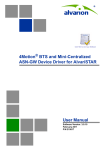
Figure 1-1 illustrates the entire service provider environment and 4Motion
solution elements within the radio access network, core network and subscriber
environment.
Figure 1-1: 4Motion Solution Elements
Alvarion believes that compliance with standard-driven open architecture protects
the infrastructure investment, and opens the system to a variety of fully
interoperable end-user devices. As such, 4Motion is designed with open
architecture and interfaces according to the WiMAX Forum networking working
group (NWG) profile C, which supports openness and enables flat as well as
hierarchical topologies. In addition, by keeping the radio resource management
functionality in the Base Transceiver Station only, Profile C delivers a faster,
optimized handover mechanism.
4
4Motion System Manual
4Motion Solution
1.2.2
WiMAX Network Reference Model
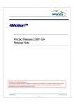
Figure 1-2 and Figure 1-3 show the basic mobile WiMAX network architecture,
with a single ASN-GW and with multiple ASN-GWs, as defined by the WiMAX
Forum NWG.
Figure 1-2: Mobile WiMAX Network Reference Model
4Motion System Manual
5
Chapter 1 - System Description
Figure 1-3: ASN Reference Model containing Multiple ASN-GWs
The various components and entities involved in the networking architecture are:
1.2.2.1
Access Service Network (ASN)
An ASN is defined as a complete set of network functions needed to provide radio
access to a WiMAX subscriber. The ASN provides the following mandatory
functions:
WiMAX Layer-2 (L2) connectivity with WiMAX mobile station (MS)
Transfer of AAA messages to the WiMAX subscriber's home network service
provider (H-NSP) for authentication, authorization and session accounting for
subscriber sessions
Network discovery and selection of the WiMAX subscriber's preferred NSP
Relay functionality for establishing Layer-3 (L3) connectivity with a WiMAX MS
(i.e. IP address allocation)
Radio resource management
ASN-CSN tunneling
ASN anchored mobility
6
4Motion System Manual
4Motion Solution
An ASN is comprised of network elements such as one or more base transceiver
stations and one or more ASN gateways. An ASN may be shared by more than one
connectivity service network (CSN).
1.2.2.2
Connectivity Service Network (CSN)
A CSN is defined as a set of network functions that provide IP connectivity
services to WiMAX subscribers. A CSN may offer the following functions:
MS IP address and endpoint parameter allocation for user sessions
Internet access
AAA proxy or server
Policy and admission control based on user subscription profiles
ASN-CSN tunneling support
WiMAX subscriber billing and inter-operator settlement
WiMAX services such as location-based services, connectivity for peer-to-peer
services, provisioning, authorization and/or connectivity to IP multimedia
services, and facilities to support lawful intercept services such as those
compliant with Communications Assistance Law Enforcement Act (CALEA)
procedures
A CSN is comprised of network elements such as routers, proxy/servers, user
databases, and inter-working gateway devices.
1.2.2.3
Network Access Provider (NAP)
An NAP is a business entity that provides WiMAX radio access infrastructure to
one or more WiMAX network service providers (NSPs). A NAP implements this
infrastructure using one or more ASNs.
1.2.2.4
Network Service Provider (NSP)
An NSP is a business entity that provides IP connectivity and WiMAX services to
WiMAX subscribers compliant with the established service level agreement. The
NSP concept is an extension of the Internet service provider (ISP) concept,
providing network services beyond Internet access. To provide these services, an
NSP establishes contractual agreements with one or more NAPs. An NSP may also
establish roaming agreements with other NSPs and contractual agreements with
4Motion System Manual
7
Chapter 1 - System Description
third-party application providers (e.g. ASP, ISP) for the delivery of WiMAX services
to subscribers. From a WiMAX subscriber standpoint, an NSP may be classified as
a home or visited NSP.
1.2.2.5
Base Station (BS)
The WiMAX BS is an entity that implements the WiMAX MAC and PHY in
compliance with the IEEE 802.16e standard. A BS operates on one frequency
assignment, and incorporates scheduler functions for uplink and downlink
resources.
The basic functionality of the BS includes:
IEEE 802.16e OFDMA PHY/MAC entity
R6 and R8 functionality according to NWG definitions
Extensible Authentication Protocol (EAP) relay
Control message authentication
User traffic authentication and encryption
Handover management
QoS service flow management entity
1.2.2.6
ASN Gateway (ASN-GW)
The ASN-GW is a network entity that acts as a gateway between the ASN and
CSN. The ASN functions hosted in an ASN-GW may be viewed as consisting of two
groups - the decision point (DP) and enforcement point (EP). The EP includes
bearer plane functions, and the DP includes non-bearer plane functions.
The basic DP functionality of the ASN-GW includes:
Implementation of EAP Authenticator and AAA client
Termination of RADIUS protocol against the selected CSN AAA server (home or
visited AAA server) for MS authentication and per-MS policy profile retrieval
Storage of the MS policy profile
Generation of authentication key material
8
4Motion System Manual
4Motion Solution
QoS service flow authorization entity
AAA accounting client
The basic EP functionality of the ASN-GW includes:
Classification of downlink data into generic routing encapsulation (GRE)
tunnels
Packet header suppression functionality
DHCP functionality
Handover functionality
The WIMAX Forum NWG has adopted two different approaches for ASN
architecture - centralized and distributed: In the centralized approach there is at
least one central ASN-GW, and the BTS NPU operates in transparent mode, as
shown in Figure 1-4.
Figure 1-4: Centralized Network Reference Model
4Motion System Manual
9
Chapter 1 - System Description
In the distributed approach, the BTS NPU operates in ASN-GW mode, as shown in
Figure 1-5.
Figure 1-5: Distributed Network Reference Model
Alvarion believes in providing operators with the flexibility to select the mobile
WiMAX network topology that best suits their needs and existing network
architecture. Therefore, 4Motion is designed to support both distributed and
centralized topology approaches according to WiMAX Forum NWG profile C.
1.2.2.7
Reference Points
Reference point R1 consists of the protocols and procedures between the MS
and ASN as per the air-interface (PHY and MAC) specifications (IEEE 802.16e).
Reference point R2 consists of protocols and procedures between the MS and
CSN associated with authentication, services authorization and IP host
configuration management. This reference point is logical in that it does not
reflect a direct protocol interface between the MS and CSN. The authentication
part of reference point R2 runs between the MS and CSN operated by the
home NSP, however, the ASN and CSN operated by the visited NSP may
partially process the aforementioned procedures and mechanisms. Reference
point R2 might support IP host configuration management running between
the MS and CSN (operated by either the home NSP or visited NSP).
10
4Motion System Manual
4Motion Solution
Reference point R3 consists of the set of control plane protocols between the
ASN and CSN to support AAA, policy enforcement and mobility management
capabilities. It also encompasses the bearer plane methods (e.g. tunneling) to
transfer user data between the ASN and CSN.
Reference point R4 consists of the set of control and bearer plane protocols
originating/terminating in various functional entities of an ASN that
coordinate MS mobility between ASNs and ASN-GWs. R4 is the only
interoperable reference point between similar or heterogeneous ASNs.
Reference point R5 consists of the set of control plane and bearer plane
protocols for internetworking between the CSN operated by the home NSP and
that operated by a visited NSP.
Reference point R6 consists of the set of control and bearer plane protocols
for communication between the BS and ASN-GW. The bearer plane consists of
an intra-ASN data path between the BS and ASN gateway. The control plane
includes protocols for data path establishment, modification and release
control in accordance with the MS mobility events.
Reference point R8 consists of the set of control plane message flows and
optional bearer plane data flows between the base stations to ensure a fast
and seamless handover. The bearer plane consists of protocols that allow data
transfer between base stations involved in the handover of a certain MS.
It is important to note that all reference points are logical and do not necessarily
imply a physical or even direct connection. For instance, the R4 reference point
between ASN-GWs might be implemented across the NAP internal transport IP
network, in which case R4 traffic might traverse several routers from the source to
the destination ASN-GW.
4Motion System Manual
11
Chapter 1 - System Description
1.3
The Base Transceiver Station
The 4Motion solution features a multi-carrier, high-power Base Transceiver
Station (BTS). Designed for high availability and redundancy, it utilizes a central
networking and management architecture, and a range of diversity schemes.
The BTS main features include:
R1 support - 802.16e interface handling (e.g. PHY, MAC, CS, Scheduler, ARQ)
and processes such as handover, power control and network entry
R6 support - communication with ASN-GW
EAP proxy in ASN-GW mode
Handover triggering for mobility tunnel establishment - R6 (GRE tunnel)
Local QoS PEP for traffic via air interface (or SFM) and admission control
Hand-Over (HO) control function
Radio resource management agent
Key generation (TEK, KEK) and traffic encryption
The 4Motion Base Transceiver Station includes the modular BreezeMAX shelf,
Outdoor Radio Units, GPS Receiver and other components.
1.3.1
The BreezeMAX Shelf
The BreezeMAX shelf is an indoor -48 VDC powered 8U cPCI PICMG 2.x standard
shelf prepared for installation in a 19" or 21" (ETSI) rack. This chassis has a total
of nine double-Euro (6U high) slots and six single-Euro (3U high) slots. All the
12
4Motion System Manual
The Base Transceiver Station
modules are hot swappable, and high availability can be provided through
multiple redundancy schemes.
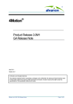
Figure 1-6: BreezeMAX Shelf (with all modules installed)
The shelf modules are:
Table 1-1: BreezeMAX Shelf Modules
Module
Description
PIU
3U high power interface unit, 1+1 redundancy, -48VDC, protection, filters
PSU
3U high power supply unit, up to 3+1 redundancy
NPU
6Uhigh network processing unit with optional ASN-GW functionality, hardware
ready for 1+1 redundancy, 1000/100 Base-T main network interface, 1000/100
Base-T cascade interface and 100/10 Base-T out-of-band management interface
AU
6U high access unit, 4-channel, 802.16e MAC-modem-baseband IF card
AVU
2U high air ventilation unit, 9+1 redundancy fans with alarm control
The six single-Euro slots are intended for one or two redundant Power Interface
Units (PIUs) and up to four redundant Power Supply Units (PSUs). One of the
double Euro slots is dedicated to the NPU module, with interfaces for network
backhaul, in-band and out-of-band (OOB) management connections. Another
4Motion System Manual
13
Chapter 1 - System Description
double-Euro slot is reserved for an optional redundant NPU (the shelf is HW-ready
for NPU redundancy). The remaining seven double-Euro slots are dedicated for
Access Unit (AU) modules, thereby enabling various network topologies and future
redundancy configurations. In addition, the shelf contains an Air Ventilation Unit
(AVU).
1.3.2
NPU
The Network Processing Unit is the controller of the Base Transceiver Station.
Serving as the central processing unit that manages the BTS components, the
NPU aggregates traffic to/from the AU modules, and transfers it to/from the IP
backbone through a dedicated Gigabit/Fast Ethernet interface. In addition, the
NPU can be operated in ASN-GW mode, in which case it also implements ASN-GW
functionality.
When operating in ASN-GW mode, the NPU implements the R3 reference point
toward the CSN, R4 reference point toward other ASN-GWs, and R6 reference
point toward AU/BSs. The R8 reference point traffic is transparently relayed
between AU/BSs (intra- or inter-BTS).
When operating in transparent mode, the NPU transparently relays R6 and R8
reference-point traffic between AU/BSs (intra- or inter-BTS).
The BreezeMAX shelf is hardware-ready for 1+1 NPU card redundancy.
The NPU main functions, when operating in transparent mode, are:
Aggregate backbone Ethernet connectivity for user and control traffic
Aggregate backbone Ethernet connectivity for management traffic (in-band or
out-of-band)
Connection to a cascaded shelf (future feature)
L2 switch forwarding capabilities
Internal and external traffic VLAN encapsulation
QoS marking
Overall operation, control and shelf management, including AU diagnostics
and control, PSU monitoring, AVU management and redundancy support
14
4Motion System Manual
The Base Transceiver Station
Local and remote extensive management support via CLI (Telnet, SSH) and
SNMP, including software download, fault and performance management
Alarm management, including external alarm inputs and activation of external
devices
Synchronization, including GPS receiver interface, clock and IF reference
generation and distribution to the shelf modules, and holdover handling
Security functionalities such as rate limiting and access control lists
When operating in ASN-GW mode, the following additional ASN-GW functions are
supported:
EAP authenticator
RADIUS AAA client
AAA accounting client
MS policy profile storage
QoS service flow authorization
Classification of downlink data into service flows
Packet header suppression functionality
DHCP functionality
Handover functionality
GRE encapsulation/decapsulation
IP-in-IP encapsulation/decapsulation
Fragmentation/reassembly
R4/R6/R3 interfaces implementation
When several shelves are collocated, the NPU cascade interface can be used for
shelf interconnection. In this architecture, the NPU that is directly connected to
4Motion System Manual
15
Chapter 1 - System Description
the backhaul implements a layer-2 connection toward the NPUs in the cascaded
shelves. Bearer, control and management traffic is sent over the cascade
connection. Synchronization and GPS backup power are sent toward the NPUs in
the cascaded shelves through the GPS/SYNC ports.
GPS synchronization cascading will be implemented in a future release.
1.3.3
AU
The Access Unit module performs the WiMAX/IEEE 802.16e BS function
according to the NWG Profile C definitions via digital signal processors (DSPs) and
field-programmable gate array (FPGA) technology. The AU module is designed to
support high-traffic throughput and enable diversity, MIMO and AAS, thereby
extending capacity and range.
The AU implements the following functionality:
802.16e multi-channel OFDMA PHY
Up to four-channel support (Tx/Rx)
Diversity and future AAS
Flexible channel bandwidth - up to 20 MHz
Flexible FFT size - up to 2048 points
Wide variety of reuse patterns
Advanced channel coding (CTC)
HARQ
Rate adaptation
High-performance CDMA detector
IF interface to RF ODU
MAC-PHY interface
Link management (network entry, basic capabilities negotiation,
authentication and registration, connection management)
16
4Motion System Manual
The Base Transceiver Station
Fragmentation/ reassembly
QoS PEP for air interface traffic
QoS DSCP marking
Scheduling - connections quota computation for all data delivery types
Frame/burst building
Power save
Handover management
Power control
R1/R6/R8 functionality
Data path mapping between R6 (GRE) and 802.16e interfaces
Traffic authentication and encryption
Authentication relay
Security key receiver
Context client/server
ID to IP address resolution for ASN entities
The AU is built according to the Software-Defined Radio SDR approach, making it
a highly flexible platform. Utilization of this approach also enables enhancing the
BS capabilities and capacity via software upgrades only, to add more features,
and to comply with future WiMAX Forum profiles. In addition, the SDR approach
prepares the AU for adaptive beam-forming. The AU design is based on Alvarion's
programmable, off-the-shelf, cutting-edge components, in order to provide a
future-proof solution with excellent cost and performance.
The AU card interfaces with the NPU card for R6/R8 functionality, as well as
control, synchronization and management between the NPU and AU.
The AU implements four receive and transmit channels, each of them is HW-ready
for up to 20 MHz bandwidth.
4Motion System Manual
17
Chapter 1 - System Description
1.3.4
PIU
The single-Euro Power Interface Unit module serves as the interface between the
DC power source and both the PSU modules and external ODU radio transceivers.
The PIU filters and stabilizes the input power, and protects the system from power
problems such as over-voltage, surge pulses, reverse polarity connection, and
short circuits. It filters high-frequency interference (radiated emissions) and
low-frequency interference (conducted emissions) at the external power source.
Each shelf contains two slots for optional 1+1 PIU redundancy. One PIU is
sufficient to support a fully populated shelf, and two modules provide redundant
power feeding (i.e. from two input sources), while avoiding current flow between
the two input sources.
1.3.5
PSU
The single-Euro Power Supply Unit module is a -48 VDC power supply unit that
generates low-voltage DC output to comply with PICMG 2.x standard
requirements. Each shelf can contain up to four PSU modules supporting N+1
redundancy configuration scheme.
Table 1-2 displays the number of PSU modules (excluding redundant units)
required for various Base Station configurations without NPU redundancy (one
NPU):
Table 1-2: PSU Requirements, Configurations with one NPU (excluding PSU
redundancy)
1.3.6
Number of AUs
Minimum Required Number of PSUs
1-4
2
5-6
3
AVU
The 2U-high AVU includes a 1U-high integral chamber for inlet airflow and a
1U-high fan tray with an internal alarm module. To support high availability, the
fan tray includes 10 brushless fans (9 fans are sufficient for cooling a fully-loaded
shelf). Fan failure is indicated by both the front panel LEDs and a trap sent to the
management system. To further support high availability, the chassis may
operate without the hot-swappable fan tray for up to 10 minutes until the AVU is
replaced.
18
4Motion System Manual
The Base Transceiver Station
1.3.7
ODU
The outdoor unit (ODU) is a high-power, multi-carrier radio unit that connects to
one or more external antennas. It is designed to provide high system gain and
interference robustness utilizing high transmit power and low noise figure. It is
HW-ready for supporting a bandwidth of up to 20 MHz, enabling future options
such as increased capacity through the use of a multiplexer or wider frequency
channels.
The following ODU port configurations will be available:
1x1(1Rx by 1 Tx): One receive port, one transmit port
2x1 (2Rx by 1Tx): Two receive ports, one transmit port
4x2 (4Rx by 1Tx): Four receive ports, two transmit ports
In the current release only 1x1 and 4x2 ODUs are available.
The wide range of ODU types will enable efficient utilization of various second and
fourth order transmit and receive diversity schemes.
The following table provides details on the currently available ODUs following the
WiMAX Forum’s definitions:
4Motion System Manual
19
Chapter 1 - System Description
Table 1-3: ODU Types
Band (GHz)
ODU Frequency Range
(MHz)
ODU Port
Configuration
ODU Bandwidth
(MHz)
ODU Max Tx
Power (dBm)
2.3
2300-2360
1Rx by 1Tx
Up to 10
36
2.5
2496-2602 (band A)
1Rx by 1Tx
Up to 10
36
2590-2690 (band B)
1Rx by 1Tx
Up to 10
36
2496-2602 (band A)
4Rx by 2Tx
Up to 20
38
2590-2690 (band B)
4Rx by 2Tx
Up to 20
38
3400-3455
1Rx by 1Tx
Up to 14
34
3445-3500
1Rx by 1Tx
Up to 14
34
3500-3555
1Rx by 1Tx
Up to 14
34
3545-3600
1Rx by 1Tx
Up to 14
34
3400-3600
4Rx by 2Tx
Up to 20
37
3600-3800
4Rx by 2Tx
Up to 20
37
3.x
1.3.8
Power Feeder
The PIU can support a maximum current of 58 A (@-40.5 VDC). In certain
installations with a relatively high number of ODUs this current may not be
sufficient to power the shelf and all the ODUs. In such installations the ODU
Power Feeder is used as an additional power source providing power (-48 VDC) to
ODUs. It transfers transparently all signals between the AU and the ODU, while
injecting DC power received from an external source. Each ODU Power Feeder
unit can serve up to four ODUs. Up to three ODU Power Feeder units can be
installed in a 1U high Power Feeder panel.
The Power Feeder is not applicable for the configurations supported in the current
release. It will be necessary in the future to support configurations with 6 AUs
where each AU is connected to either six 1x1 ODUs or one 4x2 ODU.
1.3.9
Antenna
In the 4Motion architecture, the antenna is approached as an independent
element. This provides the operator with the flexibility to select the antennas
source according to its supplier policy. To ensure the availability of antennas that
complement the 4Motion solution, Alvarion works closely with several antenna
suppliers to ensure availability of antennas that comply with its requirements.
In cases where the operator prefers other antenna vendors, Alvarion can provide a
recommended antenna specification based on the required antennas types.
20
4Motion System Manual
The Base Transceiver Station
For more information on recommended antenna configurations and required
antennas refer to Appendix A.
1.3.10 GPS
GPS is used to synchronize the air link frames of Intra-site and Inter-site located
Base Transceiver Stations to ensure that in all Base Stations the air frame will
start at the same time, and that all Base Stations will switch from transmit
(downlink) to receive (uplink) at the same time. This synchronization is necessary
to prevent Intra-site and Inter-site interference and Base stations saturation
(assuming that all Base Stations are operating with the same frame size and with
the same DL/UL ratio).
In order for the system to be synchronized, the GPS have to first acquire at least 4
satellites. After that the GPS reception can be reduced to 1 satellite.If no satellite
is received the BTS will go to holdover state where internal clock is provided to
synchronize the BTS.
1.3.10.1
Outdoor GPS Receiver
The all-outdoor GPS Receiver is a pole mountable GPS receiver and antenna in a
single environmentally protected enclosure. The GPS Receiver is powered by a 12
VDC power source, supplied to it by the NPU. The RS-422 interface allows
installation at distances up to 100m.
4Motion System Manual
21
Chapter 1 - System Description
1.4
Element Management Systems
The end-to-end IP-based architecture of the system enables full management of
all components, using standard management tools. An SNMP agent in the NPU
implements proprietary MIBs for remote setting of operational modes and
parameters of the Base Transceiver Station equipment. Security features
incorporated in the equipment restrict the access for management purposes.
Alvarion offers the following management tool:
1.4.1
AlvariSTAR™
AlvariSTAR is a comprehensive carrier-class Element Management System (EMS)
for Alvarion’s Broadband Wireless Access systems. AlvariSTAR is designed for
today's most advanced Network Operation Centers (NOCs), providing the network
Operation, Administration and Maintenance (OA&M) staff and managers with all
the network surveillance, monitoring and configuration and service provisioning
capabilities required to effectively manage the network while keeping the
resources and expenses at a minimum.
AlvariSTAR offers the network's OA&M staff with a unified, scalable and
distributable management system. Utilizing distributed client-server architecture,
the user is provided with a robust, scalable and fully redundant management
system in which all single points of failure can be avoided.
AlvariSTAR provides the following management functionality:
Device Discovery
Device Inventory
Topology
Fault Management
Configuration Management
Service Management
Data Collection
Performance Monitoring
22
4Motion System Manual
Element Management Systems
Device embedded software upgrade
Security Management
Northbound interface to other Network Management Systems.
4Motion System Manual
23
Chapter 1 - System Description
1.5
Specifications
1.5.1
Modem & Radio
Table 1-4: General Modem & Radio Specifications
Item
Description
Operation Mode
TDD
Channel Bandwidth
5 MHz
10 MHz
1.5.2
Central Frequency Resolution
0.125 MHz (actual configurable frequencies depend on the
local radio regulations and allocated spectrum)
Modulation
OFDM modulation, 1024/512 FFT points;
QPSK, QAM16, QAM64
Access Method
OFDMA
FEC
Convolutional Turbo Coding: 1/2, 2/3, 3/4, 5/6
Sensitivity
Table 1-5: Sensitivity, AWGN @ PER=1%
24
Modulation & Coding
Sensitivity (dBm),
5 MHz Bandwidth
Sensitivity (dBm),
10 MHz Bandwidth
QPSK 1/2
-97.3
-94.2
QPSK 3/4
-94.9
-91.8
16QAM 1/2
-92.2
-89.1
16QAM 3/4
-88.3
-85.2
64QAM1/2
-86.8
-83.7
64QAM2/3
-83.0
-79.9
64QAM3/4
-82.2
-79.1
64QAM5/6
-81.0
-77.9
4Motion System Manual
Specifications
1.5.3
ODUs
1.5.3.1
2.3 GHz Band
Table 1-6: 1x1 ODU-HP-2.3 Specifications
Item
Description
Frequency Band
2300-2360 MHz
Ports Configuration
1x1 (1Rx, 1Tx)
Bandwidth Support
Up to 10 MHz, 5 & 10 MHz SAW filters
Maximum Tx Power )
36 dBm
Tx Power Control Range
6 dB, in 1 dB steps
Tx Power Accuracy
+/- 1 dB
Maximum Input Power @ antenna port
-60 dBm before saturation, -8 dBm before damage
Noise Figure
4.6 dB typical, 6.0 dB maximum
Dimension
329 x 157 x 169 mm
Weight
6.1 Kg
Connectors
ANT: N-Type jack, 50 Ohm, lightning protected
IF: TNC jack, 50 Ohm, lightning protected
Power Source
-40.5 to -60 VDC over the IF cable
Power Consunption
Transmit - 89W maximum, 75W typical
Receive - 15W maximum, 9W typical
4Motion System Manual
25
Chapter 1 - System Description
1.5.3.2
2.5 GHz Band
Table 1-7: 2.5 GHz Band 1x1 ODUs Specifications
Item
Description
Frequency Band
ODU-HP-2.5A: 2496-2602 MHz (Band A)
ODU-HP-2.5B: 2590-2690 MHz (Band B)
Ports Configuration
1x1 (1Rx, 1Tx)
Bandwidth Support
Up to 10 MHz
Maximum Tx Power )
36 dBm
Tx Power Control Range
6 dB, in 1 dB steps
Tx Power Accuracy
+/- 1 dB
Maximum Input Power @
antenna port
-60 dBm before saturation, -8 dBm before damage
Noise Figure
4.6 dB typical, 6.0 dB maximum
Dimension
329 x 157 x 209 mm
Weight
6.1 Kg
Connectors
ANT: N-Type jack, 50 Ohm, lightning protected
IF: TNC jack, 50 Ohm, lightning protected
Power Source
-40.5 to -60 VDC over the IF cable
Power Consunption
Transmit - 89W maximum, 75W typical
Receive - 15W maximum, 9W typical
26
4Motion System Manual
Specifications
Table 1-8: 2.5 GHz Band 4x2 ODUs Specifications
Item
Description
Frequency Band
ODU-2496-2602-000N-38-4x2-N-0: 2496-2602 MHz (Band A)
ODU-2590-2690-000N-38-4x2-N-0: 2590-2690 MHz (Band B)
Ports Configuration
4x2 (4Rx, 2Tx)
Bandwidth Support
Up to 20 MHz
Maximum Tx Power )
38 dBm
Tx Power Control Range
10 dB, in 1 dB steps
Tx Power Accuracy
+/- 1 dB
Maximum Input Power @
antenna port
-60 dBm before saturation, -8 dBm before damage
Noise Figure
4.5 dB typical, 5.5 dB maximum
Dimension
420 x 340 x 270 mm
Weight
15 Kg
Connectors
ANT: 4 x N-Type jack, 50 Ohm, lightning protected
IF: 4 x TNC jack, 50 Ohm, lightning protected
Power Source
-40.5 to -60 VDC over the IF cable
Power Consunption
Transmit - 284W maximuml
Receive - 70W maximum
4Motion System Manual
27
Chapter 1 - System Description
1.5.3.3
3.x GHz Band
Table 1-9: 3.x GHz Band 1x1 ODUs Specifications
Item
Description
Frequency Band
ODU-HP-TDD-3.4a: 3400-3455 MHz
ODU-HP-TDD-3.4b: 3445-3500 MHz
ODU-HP-TDD-3.5a: 3500-3555 MHz
ODU-HP-TDD-3.5b: 3545-3600 MHz
Ports Configuration
1x1 (1Rx, 1Tx)
Bandwidth Support
Up to 14 MHz
Maximum Tx Power
34 dBm
Tx Power Control Range
10 dB, in 1 dB steps
Tx Power Accuracy
+/- 1 dB
Maximum Input Power @
antenna port
-60 dBm before saturation, -8 dBm before damage
Noise Figure
4.5 dB typical, 5.5 dB maximum
Dimension
329 x 157 x 169 mm
Weight
6.1 Kg
Connectors
ANT: N-Type jack, 50 Ohm, lightning protected
IF: TNC jack, 50 Ohm, lightning protected
Power Source
-40.5 to -60 VDC over the IF cable
Power Consunption
Transmit - 90W maximum, 62W typical
Receive - 20W maximum, 14W typical
28
4Motion System Manual
Specifications
Table 1-10: 3.x GHz Band 4x2 ODUs Specifications
Item
Description
Frequency Band
ODU-3400-3600-000N-37-4x2-N-0: 3400-3600 MHz
ODU-3600-3800-000N-37-4x2-N-0: 3600-3800 MHz
Ports Configuration
4x2 (4Rx, 2Tx)
Bandwidth Support
Up to 20 MHz
Maximum Tx Power )
387 dBm
Tx Power Control Range
10 dB, in 1 dB steps
Tx Power Accuracy
+/- 1 dB
Maximum Input Power @
antenna port
-60 dBm before saturation, -8 dBm before damage
Noise Figure
4.5 dB typical, 5.5 dB maximum
Dimension
420 x 340 x 270 mm
Weight
15 Kg
Connectors
ANT: 4 x N-Type jack, 50 Ohm, lightning protected
IF: 4 x TNC jack, 50 Ohm, lightning protected
Power Source
-40.5 to -60 VDC over the IF cable
Power Consunption
Transmit - 216W maximuml
Receive - 24W maximum
4Motion System Manual
29
Chapter 1 - System Description
1.5.4
AU - ODU Communication
Table 1-11: AU - ODU Communication
Item
Description
IF Frequency
Tx: 240 MHz
Rx: 140 MHz
Ref Synchronization Frequency
64 MHz
Bi-Directional Control Frequency
14 MHz
IF cable Impedance
50 Ohm
Maximum IF cable Attenuation
10 dB @ 240 MHz
7.5 dB @ 140 MHz
8 dB @ 64 MHz
1.5.5
Minimum IF cable Shielding Effectiveness
90 dB in the 10-300 MHz band
Maximum IF cable Return Loss
20 dB in the 10-300 MHz band
Maximum IF cable DC Resistance
1.5 Ohm
Data Communication (Ethernet Interfaces)
Table 1-12: Data Communication (Ethernet Interfaces)
30
Item
Description
Standard Compliance
IEEE 802.3 CSMA/CD
Speed
NPU Data Port
100/1000 Mbps, Full Duplex with Auto Negotiation
NPU Management Port
10/100 Mbps, Half/Full Duplex with Auto Negotiation
NPU Cascade Port
100/1000 Mbps, Full Duplex with Auto Negotiation
AU Calibration Port
10/100 Mbps, Half/Full Duplex with Auto Negotiation
4Motion System Manual
Specifications
1.5.6
Configuration and Management
Table 1-13: Configuration and Management
Item
Description
Out Of Band (OOB) Management
Telnet via Management port
SSH via Management port
SNMP via Management port
Telnet via Cascade port
SSH via Cascade port
SNMP via Cascade port
Monitor port (serial interface)
In Band (IB) Management via Data Port
SNMP
Telnet
SSH
SNMP Agents
SNMP ver 2 client
MIB II (RFC 1213), Private MIBs
Software Upgrade
Using TFTP
Configuration Upload/Download
Using TFTP
4Motion System Manual
31
Chapter 1 - System Description
1.5.7
Standards Compliance, General
Table 1-14: Standards Compliance, General
Type
Standard
EMC
ETSI EN 301 489-1/4
Safety
EN60950-1 (CE)
UL 60950-1 US/C (TUV)
Environmental
ETS 300 019:
Part 2-1 T 1.2 & part 2-2 T 2.3 for indoor & outdoor
Part 2-3 T 3.2 for indoor
Part 2-4 T 4.1E for outdoor
ETSI EN 302 326
Radio
FCC part 15, part 27
1.5.8
Environmental
Table 1-15: Environmental Specifications
Type
Unit
Details
Operating
Temperature
Outdoor units
ODUs: -40°C to 55°C
Operating
Humidity
32
Outdoor GPS Receiver: -40°C to 85°C
Indoor equipment
0°C to 40°C
Outdoor units
8%-100%, weather protected
Indoor equipment
5%-95% non condensing
4Motion System Manual
Specifications
1.5.9
Mechanical and Electrical
1U = 44.45 mm (1.75”).
1HP = 5.08 mm (0.2”)
1.5.9.1
BreezeMAX Shelf
Table 1-16: BreezeMAX Shelf, Mechanical & Electrical Specifications
1.5.9.2
Item
Description
Dimensions
8U ETSI type shelf, 8U x 43.2 x 24 cm
Weight
6.9 Kg (excluding AVU)
PIU
Table 1-17: PIU, Mechanical & Electrical Specifications
1.5.9.3
Item
Description
Dimensions
3U x 5HP x 16 cm
Weight
0.45 Kg
Power Source
-40.5 to -60 VDC
Power Dissipation
35W maximum (active PIU)
Maximum Supplied Current
58A
-48V Connector
5 pin/40A D-Type plug
PSU
Table 1-18: PSU, Mechanical & Electrical Specifications
Item
Description
Dimensions
3U x 5HP x 16 cm
Weight
0.7 Kg
Power Output
300W maximum output power
Efficiency: 80% minimum
4Motion System Manual
33
Chapter 1 - System Description
1.5.9.4
NPU
Table 1-19: NPU, Mechanical & Electrical Specifications
Item
Description
Dimensions
6U x 7HP x 16 cm
Weight
0.7 Kg
Power Consumption
68W maximum, 61W typical
Connectors
1.5.9.5
DATA
100/1000Base-T (RJ-45) with 2 embedded LEDs
MGMT
10/100Base-T (RJ-45) with 2 embedded LEDs
GPS/SYNC IN
15-pin micro D-Type jack
GPS/SYNC OUT
15-pin micro D-Type jack
CSCD
100/1000Base-T (RJ-45) with 2 embedded LEDs
ALRM IN/OUT
25-pin micro D-Type jack
MON
3-pin low profile jack
AU
Table 1-20: AU, Mechanical & Electrical Specifications
Item
Description
Dimensions
6U x 7HP x 16 cm
Weight
0.6 Kg
Power Consumption
74W maximum, 66W typical
Connectors
1.5.9.6
ODU1 - ODU4
4 x TNC jack, lightning protected
CAL UNIT
10/100Base-T (RJ-45) with 2 embedded LEDs
GPS Receiver
Table 1-21: GPS Receiver, Mechanical & Electrical Specifications
34
Item
Description
Dimensions
Tubular enclosure, 15.5 D x 12.7 H cm
Weight
0.363 Kg
Power Source
12 VDC from the NPU
Power Consumption
6W maximum
Connector
12-pin round plug
4Motion System Manual
Specifications
1.5.9.7
ODU Power Feeder
Table 1-22: ODU Power Feeder, Mechanical & Electrical Specifications
Item
Description
Dimensions
15.7 x 14.6 x 3.17 cm
Weight
0.6 Kg
Power Source
-40.5 to -60 VDC
Power Dissipation
2W per channel
Connectors
4Motion System Manual
ODU 1 - ODU 4
4 x TNC jack, lightning protected
IDU 1 - IDU 4
4 x TNC jack, lightning protected
Power
3 pin/20A D-Type plug
35
Chapter 1 - System Description
1.5.10 Antennas
1.5.10.1
2.x GHz Antennas
Table 1-23: BS-RET-DP-ANT 2.3-2.7 Specifications
36
Item
Description
Frequency Band (MHz)
2300-2700
Number of Elements
2
Polarization
Linear, +/-45°
Gain (dB)
17.3 @ 2.4 GHz
18 @ 2.6 GHz
Azimuth Beamwidth (degrees)
65
Elevation Beamwidth (degrees)
6.5
Elevation Side Lobe Level (dB)
<-18
Maximum Power (W)
250
Cross-polarization Discrimination (dB)
>15
Front-to-Back Ratio (dB)
>30
Electrical Downtilt Range (degrees)
0-10
Remote Electrical Downtilt Support
Internal motor, AISG version 2 compliant
Isolation Between Ports (dB)
>30
Return Loss (dB)
>15
RF Interface Impedance (Ohm)
50
RF Connectors
2 x N-Type jack
RET Connector
8-pin IEC 60130-9
Dimensions (mm)
1060 x 126 x 69
Weight (Kg)
6
Wind Load (Kg)
0.24 @ 160 km/h
Maximum Wind Velocity (km/h)
200
4Motion System Manual
Specifications
Table 1-24: BS-RET-DDP-ANT 2.3-2.7 Specifications
Item
Description
Frequency Band (MHz)
2300-2700
Number of Elements
4
Polarization
Linear, 2 x +/-45°
Gain (dB)
17.3 @ 2.4 GHz
18 @ 2.6 GHz
Azimuth Beamwidth (degrees)
65
Elevation Beamwidth (degrees)
6.5
Elevation Side Lobe Level (dB)
<-18
Maximum Power (W)
250
Cross-polarization Discrimination (dB)
>15
Front-to-Back Ratio (dB)
>30
Electrical Downtilt Range (degrees)
0-10
Remote Electrical Downtilt Support
Internal motor, AISG version 2 compliant
Isolation Between Ports (dB)
>30
Return Loss (dB)
>15
RF Interface Impedance (Ohm)
50
RF Connectors
4 x N-Type jack
RET Connector
8-pin IEC 60130-9
Dimensions (mm)
1070 x 300 x 110
Weight (Kg)
13
Wind Load (Kg)
0.48 @ 160 km/h
Maximum Wind Velocity (km/h)
200
4Motion System Manual
37
Chapter 1 - System Description
1.5.10.2
3.5 GHz Antennas
Table 1-25: BS-RET-DP-ANT 3.3-3.8 Specifications
38
Item
Description
Frequency Band (MHz)
3300-3800
Number of Elements
2
Polarization
Linear, +/-45°
Gain (dB)
18
Azimuth Beamwidth (degrees)
65
Elevation Beamwidth (degrees)
6.5
Elevation Side Lobe Level (dB)
<-18
Maximum Power (W)
200
Cross-polarization Discrimination (dB)
>15
Front-to-Back Ratio (dB)
>30
Electrical Downtilt Range (degrees)
0-10
Remote Electrical Downtilt Support
Internal motor, AISG version 2 compliant
Isolation Between Ports (dB)
>30
Return Loss (dB)
>15
RF Interface Impedance (Ohm)
50
RF Connectors
2 x N-Type jack
RET Connector
8-pin IEC 60130-9
Dimensions (mm)
760 x 126 x 69
Weight (Kg)
4.5
Wind Load (Kg)
0.17@ 160 km/h
Maximum Wind Velocity (km/h)
200
4Motion System Manual
Specifications
Table 1-26: BS-RET-DDP-ANT 3.3-3.8 Specifications
Item
Description
Frequency Band (MHz)
3300-3800
Number of Elements
4
Polarization
Linear, 2 x +/-45°
Gain (dB)
18
Azimuth Beamwidth (degrees)
65
Elevation Beamwidth (degrees)
6.5
Elevation Side Lobe Level (dB)
<-18
Maximum Power (W)
200
Cross-polarization Discrimination (dB)
>15
Front-to-Back Ratio (dB)
>30
Electrical Downtilt Range (degrees)
0-10
Remote Electrical Downtilt Support
Internal motor, AISG version 2 compliant
Isolation Between Ports (dB)
>30
Return Loss (dB)
>15
RF Interface Impedance (Ohm)
50
RF Connectors
4 x N-Type jack
RET Connector
8-pin IEC 60130-9
Dimensions (mm)
750 x 300 x 110
Weight (Kg)
10.5
Wind Load (Kg)
0.34 @ 160 km/h
Maximum Wind Velocity (km/h)
200
4Motion System Manual
39
2
Chapter 2 - Installation
In This Chapter:
“Installing the ODU” on page 42.
“Installing the Antennas” on page 61
“Installing the Base Transceiver Station (BTS) Equipment” on page 64
“Installing the ODU Power Feeder” on page 82
“Installing the Outdoor GPS Receiver” on page 86
“Connecting the GPS Cables” on page 87
Chapter 2 - Installation
2.1
Installing the ODU
The following sections describe how to install the ODU, including pole mounting
the ODU and connecting the cables.
2.1.1
Guidelines for Positioning the ODU
This section provides key guidelines for selecting the optimal installation locations
for the ODU See also Section 2.2.1 for guidelines on installing the antennas.
CAUTION
ONLY experienced installation professionals who are familiar with local building and safety codes
and, wherever applicable, are licensed by the appropriate government regulatory authorities should
install outdoor units and antennas.
Failure to do so may void the BreezeMAX product warranty and may expose the end user or
Service Provider to legal and financial liabilities. Alvarion and its resellers or distributors are not
liable for injury, damage or regulation violations associated with the installation of Outdoor Units or
antennas.
Select the optimal locations for the equipment using the following guidelines:
The ODU is pole mounted. Its location should enable easy access to the unit
for installation and testing.
When mounting several ODUs on a pole, make sure that at least one side of
the pole is clear, to enable easy access to all the ODUs.
The ODU should be installed as close as possible to the antenna.
2.1.2
IF Cables
ODUs are connected to the AU (or to the ODU Power Feeder) via IF cables carrying
both signals and power. The maximum permitted attenuation of the IF cable at
applicable frequencies, its screening effectiveness and its maximum permitted DC
resistance (the sum of the DC resistance of the inner and outer conductors) are
provided in the following table.
42
4Motion System Manual
Installing the ODU
Table 2-1: IF Cables Requirements
Item
Description
Screening Effectiveness
90 dB minimum in the 10-300 MHz band.
IF cable Impedance
50 Ohm
Maximum IF cable Attenuation
10 dB @ 240 MHz
7.5 dB @ 140 MHz
8 dB @ 64 MHz
Maximum IF cable DC Resistance
1.5 Ohm
Maximum IF cable Return Loss
20 dB in the 10-300 MHz band
Use only double shielded cables. Avoid using a single shielded cable even if it
complies with these requirements. The following table provides details on
maximum length for some popular double shielded cables.
Table 2-2: Maximum IF Cable Length (Double Shielded Cables)
Cable
Maximum Length for ODU
LMR-195
30 meters
LMR-240
60 meters
LMR-400
150 meters
4Motion System Manual
43
Chapter 2 - Installation
2.1.3
Installing the 1x1 ODU
2.1.3.1
1x1 ODU (ODU-HP) Installation Requirements
2.1.3.1.1
ODU Packing List
ODU
Pole mounting kit
2.1.3.1.2
Additional Installation Requirements
The following items are also required to install the ODU:
IF cable with two TNC connectors* (see Section 2.1.3 for details on IF cable
types and length).
Antenna* and RF cable* for connecting the antenna to the ODU.
Grounding cable with an appropriate termination.
Installation tools and materials, including appropriate means (e.g. a 1" to 4"
pole) for installing the ODU and antenna.
NOTE
Items marked with an asterisk (*) are available from Alvarion.
2.1.3.2
Pole Mounting the ODU
The ODU can be mounted on a 1" to 4" pole using one of the following options:
Special clamps and threaded rods are supplied with each unit. There are two
pairs of threaded holes on the back of the unit, enabling to use the clamps for
mounting the unit on diverse pole diameters.
The protrusions with grooves on the top backsides of the unit, and the
protrusion on the bottom backside, enable the use of 9/16" wide metal bands
(not included with the package) to secure the unit to a pole.
NOTE
Install the unit with the bottom panel, which includes the LEDs, facing downward.
44
4Motion System Manual
Installing the ODU
2.1.3.2.1
Pole Mounting the ODU Using Clamps
Figure 2-1 illustrates the method of mounting a ODU on a pole, using the clamps
and threaded rods.
Figure 2-1: ODU Pole Installation Using Special Clamps
NOTE
There is a groove on one end of the threaded rod. Insert the threaded rods with the grooves
pointing outward, as these grooves enable you to use a screwdriver to fasten the rods to the unit.
4Motion System Manual
45
Chapter 2 - Installation
2.1.3.2.2
Pole Mounting the ODU Using Metal Bands
Figure 2-2 illustrates the method of mounting a ODU on a pole, using metal
bands.
Figure 2-2: ODU Pole Installation Using Metal Band
I
46
4Motion System Manual
Installing the ODU
2.1.3.3
1x1 ODU Connectors and LEDs
Figure 2-3: Bottom Panel of the 1x1 ODU
CAUTION
Do not open the impermeability test screw - you may impair the sealing of the unit against moisture
and humidity.
Table 2-3: 1x1 ODU LEDs
Name
Description
Functionality
PWR
Power indication
Off - Power failure
Green - Power to ODU is OK, internal 3.3
VDC power supply is OK.
ALARM
AU-ODU communication and
synthesizer status indication
Off - AU-ODU communication is OK,
synthesizer is locked.
Red - AU-ODU communication failure or
synthesizer is not locked
ETH
4Motion System Manual
Not Used
47
Chapter 2 - Installation
Table 2-4: 1x1 ODU Connectors
Name
Connector
IF
TNC jack
Connection to the AU/ODU Power Feeder
N-Type jack, 50 Ohm
Connection to an external antenna
Grounding screw
Connection to ground (earth)
ANT
(GND)
48
Functionality
4Motion System Manual
Installing the ODU
2.1.4
Installing the 4x2 ODU
2.1.4.1
AU-ODU Package Contents
ODU (weight 15.5 kg +/- 1.5 kg)
Four M10X30 screws
Pole Mounting Kit: (weight ~6 kg)
»
One Carriage for 4x2 ODU
»
Four M10x265 Threaded Rods
»
Eight M10 Nuts
»
One M6X12 Grounding Screw
»
Eight M10 Spring Washers
»
Eight M10 Flat Washers
»
Two M10 Clamps
IMPORTANT
The weight of each ODU is 15.5 kg (+/- 1 kg) and the weight of the Pole Mounting
Kit is approximately 6 kg. Be sure to plan the installation accordingly. It is
recommended to use a harness to lift the units.
Install the AU-ODUs using the supplied kit only.
2.1.4.2
Sun Guard Package Content
4x2 ODU Sun Guard
Four M6X16 screws
2.1.4.3
Pole Mounting Kit for Two ODUs Package Content (Optional)
Two Carriage for 4x2 ODU
Four M10x265 Threaded Rods
Eight M10 Nuts
4Motion System Manual
49
Chapter 2 - Installation
One M6X12 Grounding Screw
Eight M10 Spring Washers
Eight M10 Flat Washers
2.1.4.4
Additional Installation Requirements
The following items are also required to install the AU-ODU:
4 IF cables with two TNC connectors* (see Section 2.1.3 for details on IF cable
types and length).
Antenna(s)* and 4 RF cables* for connecting the antenna(s) to the ODU
Grounding cable with an appropriate termination
Installation tools and materials, including appropriate means (e.g. a 1.5" to 6"
pole, a harness) for installing the ODU and antenna
NOTE
Items marked with an asterisk (*) are available from Alvarion.
2.1.4.5
4x2 ODU Installation Guidelines
The ODU can be mounted on a 1.5" to 6" pole depending on the pole construction.
To install toe ODUs it is recommended to use the optional Mounting Kit for two
ODUs available from Alvarion. The installation of more than two ODUs can be
carried out in one of the following ways:
1
Position the third ODU directly beneath one of the two ODUs, with a distance
of 30 cm between the top and bottom carriage to allow easy routing of the
cables.
2
Position the third ODU at an angle below the two ODUs. No minimum distance
is required.
2.1.4.6
Pole Mounting One ODU
1
50
Open the packaging and remove the ODU and screws.
4Motion System Manual
Installing the ODU
2
Insert the four M10X30 screws into the designated holes (Figure 2-4).
ODU
M10x30 screws
Figure 2-4: Preparing the 4x2 ODU for Installation
3
Position the carriage on the pole at the desired location.
4
Thread the four M10x265 threaded rods through the carriage and the rear
clamps (Figure 2-5).
5
Tighten on both sides using the supplied washers, spring washers and nuts.
4Motion System Manual
51
Chapter 2 - Installation
M10x265 Threaded Rods
Carriage for 4x2 ODU
M10 Clamps
M10 nuts, washers, spring washers
Figure 2-5: Mounting the Single 4x2 ODU Carriage on a Pole
6
Hang the ODU on the carriage and tighten the four M10x30 screws (Figure 2-6
and Figure 2-7).
52
4Motion System Manual
Installing the ODU
Figure 2-6: Mounting the 4x2 ODU
Figure 2-7: 4x2 ODU Mounted on Pole
4Motion System Manual
53
Chapter 2 - Installation
2.1.4.7
Pole Mounting Two ODUs
1
Prepare the two ODUs for installation as shown in Figure 2-4.
2
Position both carriages at the desired location on the pole.
3
Thread the 4 M10x265 threaded rods through one carriage and tighten using
the supplied washers, spring washers and nuts. Lean the carriage vertically on
the pole and thread the rods through the second carriage (Figure 2-8).
4
Tighten using the washers, spring washers and nuts.
M10x265 Threaded Rods
Carriage for 4x2 ODU
Carriage for ODU-HP
M10 nuts, washers, spring washers
Figure 2-8: Mounting Two Carriages on the Pole
5
Hang the ODUs on the carriages and tighten the M10x30 screws (Figure 2-9
and Figure 2-10).
54
4Motion System Manual
Installing the ODU
Figure 2-9: Mounting the two ODUs
Figure 2-10: Two ODUs Mounted on the Pole
4Motion System Manual
55
Chapter 2 - Installation
2.1.4.8
Mounting the Sun Guard
CAUTION
To avoid damage to the Sun Guard, assemble it after the ODUs are mounted on the pole.
1
Attach the Sun Guard to the front of the ODU using the four M6x16 screws
supplied with the Sun Guard.
Sun Guard
M6x16 screws
Figure 2-11: Attaching the Sun Guard to the 4x2 ODU
56
4Motion System Manual
Installing the ODU
Figure 2-12: 4x2 ODU with Sun Guard
4Motion System Manual
57
Chapter 2 - Installation
2.1.4.9
4x2 ODU Connectors and LEDs
Grounding Screw
Impermeability
Test Screw
Figure 2-13: Bottom Panel of 4x2 ODU
CAUTION
Do not open the impermeability test screw - you may impair the sealing of the unit against moisture
and humidity.
58
4Motion System Manual
Installing the ODU
Table 2-5: 4x1 ODU LEDs
Name
Description
Functionality
PWR
Power indication
Off - Power failure
Green - Power to ODU is OK, internal 3.3
VDC power supply is OK.
ALARM
AU-ODU communication and
synthesizer status indication
Off - AU-ODU communication is OK,
synthesizer is locked.
Red - AU-ODU communication failure or
synthesizer is not locked
ETH
Wireless Link Traffic
Green when there is traffic on the wireless link
Table 2-6: 4x1 ODU Connectors
Name
Connector
IF-1 to IF-4
4 x TNC jack
Connection to the AU/ODU Power Feeder
ANT-1 to ANT-4
4 x N-Type jack, 50 Ohm
Connection to an external antenna
Grounding screw
Connection to ground (earth)
(GND)
CAL-1, CAL-1
Functionality
Not used in current release
2.1.5
Connecting the Cables
2.1.5.1
Connecting the Grounding Cable
The Grounding screw (marked
) is located on the bottom panel of the outdoor
unit.
To connect the grounding cable:
1
Connect one end of a grounding cable to the grounding screw and tighten the
grounding screw firmly.
2
Connect the other end of the grounding cable to a good ground (earth)
connection.
4Motion System Manual
59
Chapter 2 - Installation
2.1.5.2
Connecting the Antenna Cable
To connect the RF cable:
1
Connect one end of the coaxial RF cable to the RF (ANT) connector located on
the bottom panel of the unit.
2
Connect the other end of the RF cable to the antenna.
3
The RF connectors should be properly sealed to protect against rain and
moisture.
2.1.5.3
Connecting the IF Cable
To connect the IF cable:
1
Connect one end of the coaxial IF cable to the IF connector located on the
bottom panel of the unit.
2
Verify that the length of the IF cable is sufficient to reach the AU/Power
Feeder. See IF cable length limitation in Section 2.1.2.
3
The IF cable connector should be properly sealed to protect against rain and
moisture.
4
60
Route the cable to the location selected for the indoor equipment.
4Motion System Manual
Installing the Antennas
2.2
Installing the Antennas
This section provides general guidelines on installation of antennas and necessary
accessories provided by Alvarion.
2.2.1
Guidelines for Positioning the Antennas
This section provides key guidelines for selecting the optimal installation locations
for the antennas.
CAUTION
ONLY experienced installation professionals who are familiar with local building and safety codes
and, wherever applicable, are licensed by the appropriate government regulatory authorities should
install outdoor units and antennas.
Failure to do so may void the BreezeMAX product warranty and may expose the end user or
Service Provider to legal and financial liabilities. Alvarion and its resellers or distributors are not
liable for injury, damage or regulation violations associated with the installation of Outdoor Units or
antennas.
Select the optimal locations for the equipment using the following guidelines:
The antennas are pole or wall mounted. Their location should enable easy
access to the unit for installation and testing.
The higher the placement of the antenna, the better the achievable link
quality.
The antenna should be installed so as to provide coverage to the intended
service area.
NOTE
The recommended minimum distance between any two antennas in neighboring sectors is 0.5
meters.
The antenna should be installed as close as possible to the ODU.
2.2.2
Antenna Installation Requirements
The following equipment is required to complete installation of the antennas,
including all equipment required for controlling the electronic downtilt of the
antennas (RET):
4Motion System Manual
61
Chapter 2 - Installation
Antennas, including mounting kit (fixed and adjustable downtilt).
Remote Cable Outdoor Termination Unit (3 Way AISG Breakout Box): One for
up to 3 antennas, 2 for 4 to 6 antennas.
Long AISG Remote Cable (available in length of 60 or 80 meter).
Remote Cable Termination Panel.
Short AISG Remote Cables (available in length of 2, 3 or 5 meter according to
the distance of the Remote Cable Outdoor Termination Unit from the
antennas): One for each antenna. An additional cable is required if two Remote
Cable Outdoor Termination Units are used.
Remote Downtilt Control Kit.
RF cables for connecting the antenna to the ODU(s).
2.2.3
Recommended Installation Procedure
2.2.3.1
Pre-Installation
1
Connect the AISG Antenna Controller to each antenna to verify that it
functions properly. Check the address of each antenna and note it together
with its planned location (azymuth) for future reference. Note that an XX
antenna (4 ports antenna) has two bands, each with its own RET adjustment.
For details on using the AISG Antenna Controller refer to the documentation
supplied with it. Return the electronic downtilt to 0 degrees to ensure that the
indicator will not be damaged during installation.
2
Prepare the short AISG Remote Cables and connect them to the Remote Cable
Outdoor Termination Unit(s). If two Remote Cable Outdoor Termination Units
should be installed, prepare and connect also the cable interconnecting the
two units. Refer to the instruction supplied with the unit. Connect the
antennas and use the AISG Antenna Controller to verify proper operation.
Disconnect the antennas and Controller (and interconnecting cable if used).
2.2.3.2
Installation
1
Install the Remote Cable Termination Panel in a 19” rack. Its placement
should enable easy connection of the AISG Antenna Controller.
62
4Motion System Manual
Installing the Antennas
2
Install the antennas according to the planned azymuth. It is recommended to
use the Adjustable Downtilt Kit and set it at 0 degrees downtilt. Refer to the
installation instructions supplied with the antennas.
3
Install the Remote Cable Outdoor Termination Unit(s) according to the
instructions supplied with the unit. The placement of the unit(s) should enable
connection of all the AISG Remote Cables to the antennas. Connect all the
cables to the antennas. If needed, connect the two units using the
pre-prepared cable.
4
Connect the long AISG Remote Cable to the Remote Cable Outdoor
Termination Unit and route it to the location of the Remote Cable Termination
Panel. Connect it to the Panel according to the instructions supplied with the
Panel.
5
Connect the AISG Antenna Controller to the Remote Cable Termination Panel
and set to downtilt of each antenna to the desired angle. For recommendation
on typical downtilt required in various scenarios refer to “Antenna Down-Tilt
Guidelines” on page 820.
4Motion System Manual
63
Chapter 2 - Installation
2.3
Installing the Base Transceiver Station
(BTS) Equipment
2.3.1
BTS Installation Requirements
2.3.1.1
Packing List
BTS Chassis:
»
Base Transceiver Station Chassis
»
AVU Air Ventilation Unit (installed)
»
Cables Tray kit
PIU (1 or 2 per chassis) High-Power Interface Unit(s). A suitable DC power
cable is supplied with each PIU.
PSU (up to 4 per chassis) Power Supply Unit(s)
NPU Network Processing Unit and Monitor cable
AU-4CH Access Unit Indoor Unit(s) as required for specific configuration
2.3.1.2
Additional Installation Requirements
The following items are also required to install the BTS:
Ethernet cable (straight) for connecting the NPU to a Hub/Switch.
NOTE
The maximum length of the Ethernet cable is 100m when operating at 100 Mbps and 70m when
operating at 1 Gbps.
A grounding cable with appropriate terminations for connecting the chassis to
the rack or another ground (earth) connection.
For installation in a 21" ETSI rack: Two 21" ETSI rack adapters
A portable PC for configuring parameters using the Monitor cable (supplied
with the NPU)
64
4Motion System Manual
Installing the Base Transceiver Station (BTS) Equipment
Other installation tools and materials
2.3.2
BTS Chassis Slot Assignments
The BTS chassis comprises 6 3U high slots and 9 6U high slots, as shown in
Figure 2-14.
Air
Ventillation
Unit
Figure 2-14: BTS Chassis Slot Assignments
The Cable Tray (the installation kit is supplied with the chassis) should be
installed on the top of the chassis front to enable convenient routing of cables
connecting to power source(s), outdoor unit(s) and other equipment.
To enable power source and/or Power Interface Unit 1+1 redundancy, two PIU
modules can be installed in the designated slots. If a single PIU module is used, it
can be inserted into either one of the two designated slots.
The number of installed PSU modules depends on the specific configuration
(number of AUs) and NPU redundancy scheme (refer to Table 2-9). If less than 4
PSU modules are used, they can be installed in any of the designated slots.
The NPU should be installed in slot number 5 (slot numbers are marked on the
Cable Guide). Slot 6 is reserved for a future redundant NPU.
Slots 1-4 and 7-9 can hold up to seven AU modules (only six AUs can be active).
Unused slots should remain covered until required.
4Motion System Manual
65
Chapter 2 - Installation
2.3.3
Power Requirements
Use the following table to calculate worst-case power source requirements for the
BTS equipment:
Table 2-7: Power Requirements, BTS Equipment
Unit
Details
Power Source
-40.5 to -60 VDC
PIU
Power Consumption: 35W maximum (active PIU)
Maximum Supplied Current: 58 A
PSU
300W max output power
Efficiency: 80% minimum
NPU
68W maximum, excluding GPS Receiver (6W maximum)
AU-4CH
46W maximum
ODU-2.x GHz
Tx (DL): 89W maximum
Rx (UL): 15W maximum
ODU-3.x GHz
Tx (DL): 90W maximum
Rx (UL): 20W maximum
AVU
40W maximum, 23W typical
Outdoor GPS Receiver
6W maximum
NOTE
The PSU(s) do not supply power to the ODUs that are powered directly from the PIU via the
backplane and the AU cards. The PIU can support up to a maximum of 20 1x1 ODUs. Additional
ODUs should be powered from ODU Power Feeders (not applicable for current release).
Power Calculation Example:
Configuration: A 2.x GHz BTS with 3 AU cards and 4 1x1 ODUs connected to each
AU. Uplink-Downlink split (allocation ratio) of 12-34.
Maximum power consumption that should be supplied by PSUs:
NPU: 68W
3 AUs: 3*46=138W
AVU: 40W
GPS Receiver: 6w
Total maximum power supplied by PSUs: 252W
66
4Motion System Manual
Installing the Base Transceiver Station (BTS) Equipment
Total maximum power required excluding ODUs: 252/0.8 (PSUs Efficiency) + 35
(PIU) = 350W
When calculating the power requirements associated with the ODUs, we should
distinguish between the peak power consumption (maximum current during Tx)
and the average power consumption (taking into account Tx/Rx split ratio) that
affect the requirements from a backup power source.
For a 2.x GHz system, the peak power consumption of 12 ODUs under worst
conditions is 12*89 = 1068W. Thus, the maximum peak power of the system is
350 + 1068 = 1418W (35A @ -40.5 VDC).
The maximum average power consumption of each ODU, assuming UL-DL
(Rx/Tx) ratio of 12-34 is (15*12+89*34)/46 = 70W. Thus, the maximum average
power required for the whole system is 350 + 70*12 = 1190W (29.4A @ -40.5
VDC).
2.3.4
HOT SWAP Support
The NPU, AU, and PIU modules includes a blue HOT SWAP LED and a
micro-switch in the injector/ejector handle to support hot-swap control. After
releasing the ejector's button, the HOT SWAP LED should turn on, indicating that
power to/from the back-panel is disconnected and the module can be removed
safely.
2.3.5
Power Interface Unit (PIU)
The single Euro PIU module serves as the interface between the BTS site's DC
power source and the BTS Chassis Power Supply Units and external ODUs, which
receive power via the IDUs.
The PIU filters and stabilizes the BTS input power and protects the system from
power problems such as over voltage, surge pulses, reverse polarity connection
and short circuits. It also filters high frequency interference (radiated emissions)
and low frequency interference (conducted emissions) to the external power
source. Each BTS chassis contains two slots for an optional 1+1 PIU redundancy.
One PIU is sufficient to support a fully populated chassis. Two PIU modules
provide redundant power feeding (two input sources) while avoiding current flow
between the two input sources.
4Motion System Manual
67
Chapter 2 - Installation
Figure 2-15: PIU Module Front Panel
CAUTION
When replacing a PIU, disconnect power from the PIU module before inserting/ejecting it to/from
the chassis. After disconnecting from power, disconnect the power cable to avoid irreversible
damage due to potential excessively high transient current. Connect power to the PIU only after it is
fully inserted into the chassis.
Table 2-8: PIU LEDs
PWR and
MASTER/ACT LEDs
PIU Status
PWR
MASTER/
ACT
Off
Off
Chassis is not connected to power
Red
Off
Power input is out of range or PIU card is damaged. Chassis is powered by the
redundant PIU
68
4Motion System Manual
Installing the Base Transceiver Station (BTS) Equipment
Table 2-8: PIU LEDs
PWR and
MASTER/ACT LEDs
PIU Status
Red
Green
Power input is out of range or PIU card is damaged. Chassis is powered by the PIU
Green
Off
Power to PIU is OK. PIU is in redundant mode and the chassis is powered from the
other PIU
Green
Green
Power to PIU is OK. The chassis is powered from the PIU.
HOT SWAP LED
Off: Power from the module to the chassis is not disconnected, the PIU is not ready for
removal
Blue: Power from the module to the chassis can be disconnected and the PIU can be
safely removed
2.3.5.1
Preparing a Power Cable for the PIU
A 2.5m DC power cable is supplied with each chassis. Additional DC cables can
be ordered from Alvarion. If necessary, use the following instruction to prepare a
DC cable.
To prepare the power cable:
1
For a cable length up to 2.5m use a cable with 4 x 10AWG (or thicker) wires for
the power plus and an additional 10AWG (or thicker) ground wire. For a longer
cable (up to 10m), use a cable with 4 x 8AWG (or thicker) wires for the power
plus and an additional 10AWG (or thicker) ground wire.
2
The matching power connector to be used is D-SUB 5W5S Female with power
pins 40A.
3
4
Connect the cable to the power connector as follows:
»
Pin 1 (RTN): Red (10/8 AWG min wire)
»
Pin 2 (-48V): Black (10/8 AWG min wire)
»
Pin 3 (
»
Pin 4 (-48V): Black (10/8 AWG min wire)
»
Pin 5 (RTN): Red (10/8 AWG min wire)
): Ground (shield), Green/Yellow (10AWG min wire)
Attach suitable terminal rings to the side that connects to the power source.
4Motion System Manual
69
Chapter 2 - Installation
CAUTION
It is strongly recommended to always use the power cables available from Alvarion.
Due to the high current that should be supported by the cable, good workmanship is esstential in
preparing it.
2.3.6
Power Supply Unit (PSU)
The single Euro PSU module is a 48 VDC power supply unit. Each BTS chassis
can contain up to four PSU modules providing N+1 redundancy configurations.
The following table displays the number of PSU modules (excluding redundant
units) required for various BTS configurations:
Table 2-9: PSU Requirements, Configurations with one NPU (excluding PSU redundancy)
Number of AUs
Minimum Required Number of PSUs
1-4
2
5-6
3
NOTE
The PSU(s) do not supply power to the ODUs. ODUsare powered directly from the power source
via the PIU and the back plane.
70
4Motion System Manual
Installing the Base Transceiver Station (BTS) Equipment
Figure 2-16: PSU Module Front Panel
Table 2-10: PSU LEDs
LED Status
Description
PWR
ALRM
Off
Off
No power or fatal damage
Off
Red
Power input is out of range or PSU is damaged or PSU is inhibited by NPU
Green
Off
Power is OK and PSU operates properly
4Motion System Manual
71
Chapter 2 - Installation
2.3.7
Access Unit Module (AU)
The double Euro Access Unit IDU module contains the wireless MAC and modem
that enable the establishment of wireless network connection and bandwidth
management. Each AU includes four PHY channels that can be connected to
ODUs.
Figure 2-17: AU Module Front Panel
72
4Motion System Manual
Installing the Base Transceiver Station (BTS) Equipment
Table 2-11: AU LEDs
Name
Description
Function
PWR
Power indication
Off - AU is not powered
Red - AU power supply failure (low power)
Green - AU power is OK
ALRM
Alarm indication
Off - AU is OK
Red - AU failure
WLINK
Wireless link status indication
Off - No MS is associated
Green - At least one MS is associated
WACT
Transmission indication
Off - No transmission
Green - Transmission OK
SP
Spare
Not Used
IP
IP activity indication
Off - No IP activity
Green (blinking) - IP activity
ODU1 - ODU4 PWR
AU to ODU Power Indication
Off - No AU to ODU power output
Red - AU to ODU power output failure
Green - AU to ODU power output OK
ODU1 -ODU4 ALRM
AU to ODU communication
status
Off - AU-ODU communication OK
Red - AU-ODU communication failure
HOT SWAP
AU readiness for hot swap
removal
Off: Power to the module is not disconnected, the
AU is not ready for removal
Blue: Power to the module can be disconnected
and the AU can be safely removed.
4Motion System Manual
73
2.3.8
Network Processing Unit (NPU)
The NPU module serves as the central processing unit that manages the BTS's
components and the SUs served by it. It also aggregates the traffic from the AU
modules and transfers it to the IP backbone through a dedicated Gigabit/Fast
Ethernet interface. In addition, the NPU can be operated in ASN-GW mode, in
which case it also implements ASN-GW functionality.
Figure 2-18: NPU Module Front Panel
Installing the Base Transceiver Station (BTS) Equipment
Table 2-12: NPU LEDS
Name
Description
Function
MGMT Port Activity
LED
MGMT Port Activity LED
When blinking yellow indicates Ethernet activity at the
MGMT Port Integrity
LED
MGMT Port Integrity LED
When lit green indicates Ethernet physical layer is OK
DATA Port Activity
LED
DATA Port Activity LED
When blinking yellow indicates Ethernet activity at the
MGMT Port Integrity
LED
MGMT Port Integrity LED
When lit green indicates Ethernet physical layer is OK
EXT ALRM
External alarm indication
Off - No alarm
management port
data port
Red - Alarm received via the ALRM IN connector
BST ALRM
Cell site component
failure indication
Off - All 4Motion modules are OK
Red - Failure in one (or more) 4Motion modules
Blinking - During powering up of NPU
ALRM
NPU card failure
indication
Off - NPU is OK
Red - NPU failure
Blinking - During powering up of NPU
PWR
Power indication
Off - NPU is not powered
Red - NPU power failure
Green - NPU power is OK
Master
Master indication
Lits when NPU is primary
GPS/SYNC
GPS/IF clock
syncronization function
indication
Off - NPU clock is not synchronized to external source
4Motion System Manual
Green - NPU clock is synchronized to external source
75
Chapter 2 - Installation
Table 2-12: NPU LEDS
Name
Description
Function
Hot Swap
NPU readiness
NPU card insertion status indicator
Off: Card is inserted correctly into the chassis
Blue: Card insertion is in progress or is not inserted
successfully
NPU card ejection status indicator
Off: Power to the module is not disconnected, the NPU is
not ready for removal
Blue: Power to the module can be disconnected and the
NPU can be safely removed.
Table 2-13: NPU Connectors
Name
Description
Function
Data
RJ-45 connector
Used to connect the NPU to the backbone
Cable connection to a hub/switch/router: Straight
MGMT
RL-45 connector
Connection to out-of-band management
Cable connection to a PC: Crossed
Cable connection to a hub/switch/router: Straight
GP/SYNC IN
GPS/SYNC IN connector
Enables connection to a GPS Receiver
GP/SYNC OUT
GPS/SYNC OUT
connector
Supply of synchronization signals to another unit (for
ALRM IN/OUT
ALARM IN/OUT
connector
Connection to external alarms
Cascade
RJ-45 with two embedded
LEDs
Connection to cascade shelf
future use)
Cable connection to local management traffic
Cable connection to cascade shelf: Crossed
MON
MON connector
3-pin low profile connector used for accessing the NPU
through the serial command line interface
RESET
76
RESET Button
Used to perform hardware rest to the NPU
4Motion System Manual
Installing the Base Transceiver Station (BTS) Equipment
2.3.9
Connecting the BTS Chassis and Modules
The indoor equipment should be installed as close as possible to the location
where the IF cable(s) enters the building. The location of the indoor equipment
should take into account its connection to the power source(s) and to the BTS
networking equipment.
2.3.9.1
Introduction
The BTS modules include special handles for high-force insertion/extraction of
modules. Each of the 6U high modules (NPU, AU) includes two such handles,
whereas each of the 3U high-modules (PIU, PSU) includes a single handle at the
bottom of the front panel.
The bottom injector/ejector handle of the NPU and AU modules includes a
micro-switch to support hot-swap control. Second generation PIU modules also
support hot-swap, as indicated by the HOT SWAP blue LED.
To connect the BTS chassis and modules:
1
Attach the Cable Guide to the top panel of the chassis using the screws and
washers supplied with the Cable Guide.
2
Install the chassis in a 19" cabinet. For installation in a 21" cabinet, attach
suitable ETSI rack adapters to the chassis. To provide a sufficient space for
the Cable Guide and to allow air flow for preventing over-heating, leave a free
space of at least 1U between the upper covers of the chassis and other units in
the cabinet.
3
Connect one end of a grounding cable to the ground terminal located on the
rear panel of the chassis and firmly tighten the grounding screw. Connect the
opposite end of the grounding cable to a ground connection or to the cabinet, if
applicable.
4
Carefully insert the modules into the relevant slots. Secure the modules in
their alloted locations.
5
Place blank covers over all unused slots.
6
Connect the DATA port of the NPU to the backbone data equipment (use a
straight Ethernet cable to connect to a hub/switch/router). The maximum
length of the Ethernet cable is 100m when operating at 100 Mbps and 70m
when operating at 1 Gbps.
4Motion System Manual
77
Chapter 2 - Installation
7
If the MGMT port is used for remote management, connect it to the
appropriate data equipment (use a straight Ethernet cable to connect to a
hub/switch/router). The maximum length of the Ethernet cable is 100m.
8
Connect the DC power cable to the power jack of the PIU module. If a
redundant PIU is installed, connect a DC power cable also to the second PIU
module. Connect the power cord(s) to the -48 VDC power source(s), as follows.
2.3.9.2
»
Black wire to the 48 VDC contact of the power source.
»
Red wire to the + (Return) contact.
»
Ground wire to the ground.
Air Ventilation Unit (AVU)
Figure 2-19: AVU Drawer Front Panel
The 2U high, 84 HP wide AVU includes a 1U high integral chamber for inlet
airflow and a 1U high fan tray with an internal alarm module. To support a high
availability BTS, the fan tray includes 10 brush-less fans, where 9 fans are
sufficient for cooling a fully loaded chassis. To further support high availability,
the chassis can operate with the hot-swappable fan tray extracted from it for a
period of time sufficient for replacing it (up to 10 minutes).
Table 2-14: AVU LEDs
LED Status
Description
PWR
ALRM
Off
Off
No 5V power input
Red
Red
12V power failed
Green
Red
One or more fans have failed
Green
Off
AVU operates properly
78
4Motion System Manual
Installing the Base Transceiver Station (BTS) Equipment
If the red ALRM LED is on while the PWR LED is green, it indicates a failure of at
least one fan. Although the BTS chassis may continue operating with one failed
fan, it is recommended to replace the AVU as soon as possible.
2.3.10 Replacing BTS Components
2.3.10.1
Replacing an AVU
To replace an AVU drawer:
Release the four screws securing the AVU to the chassis.
Using the handle take out the faulty chassis.
Insert a new AVU drawer and tighten the screws.
2.3.10.2
Replacing an NPU
To minimize downtime and facilitate fast and easy NPU replacement, it is
recommended to maintain an updated copy of the NPU configuration. Refer to
Section 4.3.4 for details on preparing and uploading a backup file of the NPU
configuration.
1
Release the screws located on the top and bottom of the NPU's front panel.
2
Press the red button of both handles until they are unlocked.
3
Wait until the blue HOT SWAP LED turns on, indicating that the module has
been disconnected and can be removed.
4
Press the upper handle up and the lower handle down until the module is
unlocked. Firmly hold both handles and take the module out of the chassis.
5
Disconnect all IF cables connecting the AUs to the ODUs. This is necessary as
the initial configuration of the new NPU is most probably inappropriate.
6
Firmly push the new NPU module into its intended slot (slot 5).
7
Press the upper handle up and the lower handle down simultaneously until
you hear the locking click and the red buttons are released. The blue HOT
SWAP LED will briefly turn on, indicating that the module is being powered
up.
8
Secure the module in place by tightening the screws located on the top and
bottom of the front panel.
4Motion System Manual
79
Chapter 2 - Installation
9
Download the backup file using a DOS based TFTP. Use the command: tftp i
<NPU port IP address> put <file name>. The default IP address of the MGMT
port is 10.0.0.1.
10 Use the monitor program to configure the IP parameters (IP address, Subnet
Mask, Default Gateway Address) of the MGMT port. These parameters are not
affected by the loaded file.
11 Reset the system.
12 Reconnect the IF cables.
2.3.10.3
Replacing an AU
1
Disconnect all IF cables connecting the AUs to ODUs.
2
Release the screws at the top and the bottom of the AU's front panel.
3
Press the red button of both handles until they are unlocked.
4
Wait until the blue HOT SWAP LED turns on, indicating that the module has
been disconnected and can be removed.
5
Press the upper handle up and the lower handle down until the module is
unlocked. Firmly hold both handles and take the module out of the chassis.
6
Firmly push the new AU module into its intended slot.
7
Press the upper handle up and the lower handle down simultaneously until
you hear the locking click and the red buttons are released. The blue HOT
SWAP LED will briefly turn on, indicating that the module is being powered
up.
8
Secure the module in place by tightening the screws located on the top and
bottom of the front panel.
9
Reconnect the IF cables. Make sure that each ODU is connected to the
appropriate port on the AU.
10 Wait until the AU reboot process is completed. This might take few minutes.
11 Reset the AU. (To perform the reset go to the main menu of the AU, select 2 Unit Control, than select 1 - Reset and confirm the reset. Alternatively, you can
press the reset button on the front panel of the AU).
12 Go to the AU main menu and check that the SW version and all parameters
are as required.
80
4Motion System Manual
Installing the Base Transceiver Station (BTS) Equipment
13 Check that the AU operates properly, and the SUs to which service is offered
are connected to the AU.
2.3.10.4
Replacing a PIU
1
Release the screws located on the top and bottom of the PIU's front panel.
2
Press the handle’s red button until the handle is unlocked.
3
Wait until the blue HOT SWAP LED turns on, indicating that the module has
been disconnected and can be removed.
4
Disconnect the power cable from the PIU
5
Press the handle up until the module is unlocked. Firmly hold the handle and
take the module out of the chassis.
6
Firmly push the new PIU module into its intended slot.
7
Press the handle down until you hear the locking click and the red buttons are
released.
8
Secure the module in place by tightening the screws located on the top and
bottom of the front panel.
9
Connect power to the PIU only after it is fully inserted into the chassis.
4Motion System Manual
81
Chapter 2 - Installation
2.4
Installing the ODU Power Feeder
2.4.1
Installation Requirements
2.4.1.1
Packing List
A 19” panel can hold up to three ODU Power Feeder modules.
ODU Power Feeder module, including a DC power cable, four 0.5 meter IF
cables and four screws.
2.4.1.2
Additional Installation Requirements
A grounding cable with appropriate terminations for connecting the unit's
ground terminal to the rack or to a ground connection.
Other installation tools and materials
82
4Motion System Manual
Installing the ODU Power Feeder
2.4.2
The ODU Power Feeder
The ODU Power Feeder is used to provide power (-48 VDC) to the ODUs. It
transfers all signals transparently between the AU and the ODU, while injecting
DC power received from an external source. Each ODU Power Feeder unit can
serve up to four ODUs. Up to three ODU Power Feeder units can be installed in a
1U Feeder panel.
Figure 2-20: ODU Power Feeder Front Panel
Figure 2-21: ODU Power Feeder Rear Panel
Table 2-15: ODU Power Feeder Connectors
Name
Connector
Functional
IDU 1 - 4
4 x TNC jacks
Connection to ODU connectors of AUs
ODU 1 - 4
4 x TNC jacks
Connections to IF connectors of ODU units
-48V
3-pin D-Type power jack
Connection to DC power source
Grounding Screw
Connection to ground (earth)
(GND)
4Motion System Manual
83
Chapter 2 - Installation
Table 2-16: ODU Power Feeder LEDs
Name
Description
Functionality
PWR
Input power indication
Off - ODU Power Feeder is not powered
Green - ODU Power Feeder power is OK
ODU PWR 1 - 4
Output power indications
Off - ODU is not connected
Red - Power output problem (short or overload)
Green - ODU is connected and powered
2.4.2.1
Preparing a Power Cable
A 2.5m DC power cable is supplied with each ODU Power Feeder module.
Additional DC cables can be ordered from Alvarion. If necessary, use the following
instruction to prepare a DC cable.
To prepare the power cable:
1
Use a cable capable of supporting a current of at least 10A. Use a cable with
2 x 10AWG (or thicker) wires for the power plus an additional 10AWG to
20AWG ground wire.
2
The matching power connector to be used is Amphenol D-type power P/N
177TWA/3W3/SP3Y with high power socket contacts P/N 17DM53744-1.
3
4
2.4.3
Connect the cable to the power connector as follows:
»
Pin 1 (RTN): Red (10 AWG min wire)
»
Pin 2 (-48V): Black (10 AWG min wire)
»
Pin 3 (
): Ground (shield) (10AWG-20AWG wire)
Attach suitable terminal rings to the side that connects to the power source.
Installing the ODU Power Feeder
The ODU Power Feeder should be installed as close as possible to the location
where the IF cable(s) enters the building. The location of the ODU Power Feeder
should take into consideration its connection to the power source and to the BTS
equipment.
84
4Motion System Manual
Installing the ODU Power Feeder
To install the ODU Power Feeder:
1
The panel is supplied with blank covers. Release the nuts on the rear side of
the panels to remove the blank cover(s) you want to replace with ODU Power
Feeder module(s). Attach the ODU Power Feeder module(s) to the panel using
the four screws supplied with each module.
2
Place the panel with the ODU Power Feeder module(s) on a shelf/desk or
install it in a 19" cabinet, next to the BTS equipment.
3
Connect one end of a grounding cable to the grounding screw located on the
rear panel of each ODU Power Feeder module and firmly tighten the grounding
screw. Connect the other end of the grounding cable(s) to a ground (earth)
connection or to the cabinet, if applicable.
4
Connect the IDU connector(s) to the appropriate ODU connector(s) of the AU(s)
using the short (0.5 meter) IF cables supplied with the module.
5
Connect the power cord to the ODU Power Feeder’s DC socket, located on the
rear panel. Connect the other end of the power cord to the -48 VDC power
source.
6
Connect the IF cable(s) to the appropriate ODU connector(s).The other end is
already connected connected to the ODU(s). To avoid transmissions at
undesired frequencies, verify that the frequency and bandwidth parameters
are properly configured before connecting the IF cables.
4Motion System Manual
85
Chapter 2 - Installation
2.5
Installing the Outdoor GPS Receiver
Perform the following steps to install the Outdoor GPS Receiver
1
Place the bracket on a flat surface and thread the supplied pipe through the
bracket hole and into the GPS antenna. Hand-tighten until snug. Do not
over-tighten or use a tool. Make sure that the connector (male) is on the open
side of the bracket.
2
Assemble the surge protection cable onto the bracket using the supplied
screws, washers, and spring washers (2x1032). Apply torque 2.1 [N*m] (19.2
[lbs*in]). Make sure that the female connector faces the antenna.
3
Use a 1032 screw, washer, and spring washer to connect the surge protector’s
grounding cable to the bracket. Apply torque 2.1 [N*m] (19.2 [lbs*in]).
4
Connect the surge protector cable (female connector) to the GPS antenna
connector (male). Use the groove on the cable connector (indicatd by an arrow)
as a guide. It aligns with the tenon in the connector on the GPS side. Turn the
locking ring on the cable connector clockwise to secure the connection. Do not
over-tighten.
5
Use the supplied clamps to assemble the GPS and bracket on a pole. Use the
M8 nuts, washers, and spring washers to lock the clamps to the bracket.
Apply torque 9 [N*m] (80 [lbs*in]).
86
4Motion System Manual
Connecting the GPS Cables
2.6
Connecting the GPS Cables
The Outdoor GPS Receiver is connected to the GPS/SYNC IN connector. Before
connecting the cable, make sure that the length of the cable is sufficient to reach
the NPU.
To connect the Ethernet cable:
1
Connect the 12-pin round connector (female) of the Cat. 5E Ethernet cable to
the male connector of the surge protector. Use the groove on the cable
connector (indicated by an arrow) as a guide. It aligns with the tenon in the
connector on the surge protector side. Turn the locking ring on the cable
connector clockwise to secure the connection. Do not over-tighten.
2
Fix the cable onto the pole using a cable strip. Route the cable to the location
selected for the indoor equipment.
3
Crimp the other end of the Cat. 5E Ethernet cable with an RJ-45 connector
and connect it to the indoor GPS adapter cable. Connect the other end of the
indoor GPS adapter cable to GPS/SYNC IN connector.
4Motion System Manual
87
3
Chapter 3 - Commissioning
In This Chapter:
“Initial NPU Configuration” on page 90
“Completing the Site Configuration Using AlvariSTAR” on page 94
Chapter 3 - Commissioning
3.1
Initial NPU Configuration
3.1.1
Introduction
After completing the installation process, as described in the preceding chapter,
some basic NPU parameters must be configured locally using the CLI via the MON
port of the NPU.
Refer to Chapter 4 for information on how to access the CLI either via the MON
port or via Telnet and how to use it.
The following sections describe the minimum mandatory configuration actions
required to allow remote configuration of the site and to enable discovery by the
EMS system:
3.1.2
1
”NPU Local Connectivity”
2
”Site Connectivity”
3
”ACL Definition”
4
”Static Route Definition”
5
”SNMP Manager Definition”
6
”Site ID Definition”
NPU Local Connectivity
Refer to “Accessing the CLI from a Local Terminal” on page 109 for details on
connecting locally to the NPU.
Clear existing site configuration (must be executed for "used” NPUs): Restore to
factory default and reboot using the following command:
npu# restore-factory-default
3.1.3
Site Connectivity
3.1.3.1
Connectivity Mode
The connectivity mode determines how traffic is to be routed between the NPU and
the BSs, AAA server and external Management System servers.
The default connectivity mode is In-Band (IB) via the Data port. Alternatively, the
NPU can be managed Out-Of-Band (OOB) via the dedicated Management port.
90
4Motion System Manual
Initial NPU Configuration
To view the current and configured connectivity mode, use the command:
npu# show connectivity mode
To change the connectivity mode to Out-Of-Band, use the command:
npu(config)# connectivity mode outband (for details refer to “Configuring the IP
Connectivity Mode” on page 132).
3.1.3.2
VLANs Translation (Outband Connectivity Mode)
When using In-Band connectivity via the Data port, the default VLAN ID for
management packets is 12. The default VLAN ID for data packets is 11. If different
VLAN IDs are used in the backbone, the VLANs should be translated accordingly.
To enable VLAN translation and configure the required VLANs translation, run the
following commands (the examples are for backhaul Data VLAN ID 30 and
Management VLAN ID 31):
1
Enable the Data port configuration mode (for details refer to “Enabling the
Interface configuration mode” on page 136):
npu(config)# interface gigabitethernet 0/10
2
Enable VLAN translation (for details refer to “Enabling/Disabling VLAN
Translation” on page 145): npu(config-if)# vlan mapping enable
3
Translate data VLAN 11 to the backhaul data VLAN 30 (for details refer to
“Creating a VLAN Translation Entry” on page 146):
npu(config-if)# vlan mapping 11 30
4
Translate management VLAN 11 to the backhaul management VLAN 31:
npu(config-if)# vlan mapping 12 31
5
Exit the interface configuration mode: npu(config-if) exit
6
To view the VLAN mapping parameters, run the command:
npu# show interface gigabitethernet 0/10 vlan mapping
3.1.3.3
External Management Interface
To configure the necessary parameters of the External Management interface used
for connectivity with the EMS system, run the following commands:
1
Enable the External Management interface configuration mode (for details
refer to “Enabling the Interface configuration mode” on page 136):
npu(config)# interface external-mgmt
2
Disable the interface to allow configuring its parameters:
npu(config-if)# shutdown
4Motion System Manual
91
Chapter 3 - Commissioning
3
Configure the IP address (x.x.x.x) and subnet mask (y.y.y.y). For details refer
to “Assigning an IP address to an interface” on page 155:npu(config-if)# ip
address x.x.x.x y.y.y.y
3.1.3.4
4
Configure the MTU of the interface to 1500 bytes: npu(config-if)# mtu 1500
5
Enable the interface: npu(config-if)# no shutdown
6
Exit the interface configuration mode: npu(config-if) exit
Apply Changes in Site Connectivity Configuration
The system must be reset to apply the changes: npu# reset
3.1.4
ACL Definition
For details on ACLs refer to “Configuring ACLs” on page 209.
1
Create a standard ACL (number 1) and enable the ACL configuration mode:
npu(config)# "ip access-list standard 1
2
For initial configuration, permit traffic from any source address to any
destination address: npu(config-std-nacl)# "permit any any.
3
Terminate the ACL configuration mode: npu(config-std-nacl)# exit
4
Enable the NPU virtual interface configuration mode:
npu(config)# "interface npu-host
5
Attach the ACL to the NPU virtual interface:
npu(config-if)# "ip access-group name 1
6
Terminate the NPU virtual interface configuration mode: npu(config-if)# exit
7
Enable the AUs virtual interface configuration mode:
npu(config)# "interface all-au
8
Attach the ACL to the AUs virtual interface:
npu(config-if)# "ip access-group name 1
9
3.1.5
Terminate the AUs virtual interface configuration mode: npu(config-if)# exit
Static Route Definition
Static Route must be configured whenever the EMS server and the NPU are on
different subnets. For more details refer to “Adding a Static Route” on page 206.
Run the following command: npu(config)# "ip route 0.0.0.0 0.0.0.0 x.x.x.x"
(x.x.x.x is the IP address of default gateway, 0.0.0.0 0.0.0.0 define the IP address
92
4Motion System Manual
Initial NPU Configuration
and mask as “any destination”. Depending on your backhaul network, you may
define different IP address and mask to allow only specific destinations).
3.1.6
SNMP Manager Definition
To define the communities to be used by the SNMP manager, run the command:
npu(config)# snmp-mgr ReadCommunity public ReadWriteCommunity private.
For more details refer to “Adding an SNMP Manager” on page 406.
It is recommended to also configure also the Trap Manager parameters and enable
sending traps to the defined Trap Manager:
1
npu(config)# trap-mgr ip-source x.x.x.x port 162 TrapCommunity public
( x.x.x.x is the IP address of the EMS server). For more details refer to “Adding
a Trap Manager entry” on page 409
2
3.1.7
npu(config)# trap-mgr enable ip-source x.x.x.x
Site ID Definition
To define the site ID (Site Number): npu(config)# site identifier x
(x is the unique site identifier, a number in the range from 1 to 999999)
For more details refer to “Configuring the Unique Identifier for the 4Motion Shelf”
on page 443.
4Motion System Manual
93
Chapter 3 - Commissioning
3.2
Completing the Site Configuration Using
AlvariSTAR
3.2.1
Introduction
After completion of the initial configuration you should be able to manage the new
Site using AlvariSTAR and continue configuring (at least) all mandatory
parameters to enable the necessary services.
For details on how to use AlvariSTAR for managing 4Motion sites refer to the
AlvariSTAR and 4Motion Device Manager User Manuals.
Verify that the Site is included in the list of devices that can be managed by
AlvariSTAR. It can be added to the list of managed devices either through the
Equipment Manager (by creating a New managed device) or through the Managed
Network window (by inclusion in a range to be discovered and activation of the
Network Scan Task from the Task Manager).
To complete the minimal configuration, open the Site’s Device Manager from the
Equipment Manager and perform the following configuration steps:
1
“Site Configuration” on page 95
2
“Connectivity Configuration (optional)” on page 95
3
“Equipment Configuration” on page 95
4
“ASNGW Configuration” on page 97 (only for Distributed ASNGW topology)
5
“BS Configuration” on page 99
6
“Site Sector Configuration” on page 104
NOTE
The following sections list the minimum actions that must be performed for completing basic
configuration of the Site. Additional parameters may also be configured in order to complete the
entire configuration of the Site.
After configuring the mandatory parameters in each screen, click on the Apply button. Click Apply
even if you did not change any of the screen’s default parameters.
In some of the screens in the following sections there are no mandatory parameters but still you
must click on the Apply button to activate the default values.
94
4Motion System Manual
Completing the Site Configuration Using AlvariSTAR
3.2.2
Site Configuration
3.2.2.1
General Tab
ASN Topology - Configured is mandatory: The default is Distributed ASNGW.
Click Apply for the device to accept the configuration.
3.2.3
Connectivity Configuration (optional)
3.2.3.1
IP routing Screen
The IP Routing screen is used to define the static routes for traffic originating from
the NPU.
The static route for management traffic was already configured (see “Static Route
Definition” on page 92).
If necessary (depending on your specific backhaul network) you may configure
additional static route(s) for Bearer Traffic and/or Control Traffic. If additional
static routes were defined (or if you made any changes in the already configured
static route), click on the Apply button.
3.2.4
Equipment Configuration
3.2.4.1
Power Supply Screen
The mandatory parameters are:
1
2
PIU Card Properties (for each entry):
»
Required
»
Required HW Version (if Required is configured to Yes)
PSU Card Properties: Required (for each entry)
Click Apply for the device to accept the configuration.
3.2.4.2
AU
AU entities must be created for all installed AUs (you may create an AU entity also
for AUs that are not installed yet).
To create a new AU entity:
4Motion System Manual
95
Chapter 3 - Commissioning
1
Right click on the AU level entry in the Navigation Pane. The New AU definition
window will open.
2
In the New AU definition window, define the following:
»
AU number (AU Slot)
»
Type
»
Bandwidth
3
Click Apply.
4
In the Card Properties tab of the applicable AU click on the Apply button for
the device the accept the configuration.
5
3.2.4.3
Repeat the process for all required AU entities.
ODU
ODU entities must be created for all installed ODUs (you may create an ODU
entity also for ODUs that are not installed yet).
To create a new ODU entity:
1
Right click on the ODU level entry in the Navigation Pane. The New ODU
definition window will open.
2
In the New ODU definition window, define the following:
»
ODU number (AU Slot)
»
ODU Type
3
Click Apply.
4
In the ODU General screen of the applicable ODU, in the Ports Configuration
section, configure the Tx Power for the relevant ports (currently only ODUs
with one port are available). Click on the Apply button for the device the accept
the configuration.
5
3.2.4.4
Repeat the process for all required ODU entities.
Antenna
Antenna entities must be created for all installed and connected antennas (you
may create an Antenna entity also for antennas that are not installed/connected
yet).
96
4Motion System Manual
Completing the Site Configuration Using AlvariSTAR
To create a new Antenna entity:
3.2.4.5
1
In the Anteena screen, click on the Add New Antenna button.
2
In the Antenna Parameters section, define the following:
»
Number of Ports
»
Heading
3
Click Apply.
4
Repeat the process for all required Antenna entities.
GPS
Configured GPS Type is mandatory: The default is Trimble. If there is no GPS, the
value should be changed to None.
Click Apply for the device to accept the changes/defaults.
3.2.5
ASNGW Configuration
NOTE
ASNGW screens are available only for Distributed ASNGW topology (see also “Site
Configuration” on page 95.
3.2.5.1
AAA Screen
1
2
Configure the following mandatory parameters:
»
Primary AAA Server (IP address)
»
RADIUS Shared Secret
Click Apply for the device to accept the configuration.
3.2.5.2
Service Screen
3.2.5.2.1
Service Interface Tab
NOTE
In the current release only one Service Interface is supported..
4Motion System Manual
97
Chapter 3 - Commissioning
1
Click on the Add Service Interface button and configure the following
mandatory parameters:
2
3.2.5.2.2
»
Service Interface Name
»
Tunnel Source IP
»
Tunnel Destination IP
Click Apply for the device to accept the configuration.
Service Groups Tab
NOTE
In the current release only one Service Group is supported..
1
Click on the Add Service Group button and configure the following mandatory
parameters:
2
98
»
Name
»
Service Interface Name
»
DHCP Function Mode
»
DHCP Own IP Address
»
External DHCP Server IP Address
»
IP Address Pool From
»
IP Address Pool To
»
Add Excluded IP Addresses
»
Excluded IP Addresses List
»
Subnet Mask
»
Default Gateway IP Address
»
DNS Server IP Address
Click Apply for the device to accept the configuration.
4Motion System Manual
Completing the Site Configuration Using AlvariSTAR
3.2.5.3
SFA Screen-Service Profiles Tab
At least one Service Profile must be defined and associated with an already
defined Service Group.
1
Click on the Add Profile button and configure the following mandatory
parameters:
2
»
Name
»
Profile Status
»
Reference Service Group
Click Apply for the device to accept the configuration.
3.2.6
BS Configuration
3.2.6.1
Creating a New BS Entity
To create a new BS entity:
1
Right click on the BS level entry in the Navigation Pane. The New BS definition
window will open.
2
3.2.6.2
In the New BS definition window, define the following:
»
BS ID LSB
»
Operator ID
3
Click Apply.
4
Complete the BS configuration as described in the following sections.
Radio
3.2.6.2.1
Basic Screen
3.2.6.2.1.1 General Tab
1
Configure the following mandatory parameters:
»
Name
»
Bandwidth
»
Center Frequency
4Motion System Manual
99
Chapter 3 - Commissioning
2
Click Apply for the device to accept the configuration.
3.2.6.2.1.2 Air Frame Structure General Tab
1
2
Configure the following mandatory parameters:
»
Cell ID
»
Preamble Group
»
Segment Number
»
Frame Number Offset
»
Total Uplink Duration
Click Apply for the device to accept the configuration.
3.2.6.2.1.3 Air Frame Structure Zones Tab
1
Configure the following mandatory parameters:
»
Map Zone:
◊ Map Size
◊ Map Major Groups
◊ Basic Map Repetition
»
DownLink Data Zone
◊ Number of Sub-Channels)
◊ Permutation Base
»
Up Link Feedback Zone
◊ Number of Sub-Channels
◊ Permutation Base
»
Up Link Data Zone
◊ Number of Sub-Channels
◊ Permutation Base
◊ Start Allocation
2
100
Click Apply for the device to accept the configuration.
4Motion System Manual
Completing the Site Configuration Using AlvariSTAR
3.2.6.2.1.4 Diversity Tab
1
Configure the following mandatory parameters:
»
Downlink Data MIMO Mode
»
Cyclic Delay:
◊ Channel 1
◊ Channel 2
◊ Channel 3
◊ Channel 4
»
Linear Delay
◊ Channel 1
◊ Channel 2
◊ Channel 3
◊ Channel 4
»
Logical Stream Mapping)
◊ Channel 1
◊ Channel 2
◊ Channel 3
◊ Channel 4
»
Receive
◊ Admin Channel 1
◊ Admin Channel 2
◊ Admin Channel 3
◊ Admin Channel 4
2
Click Apply for the device to accept the configuration.
4Motion System Manual
101
3.2.6.2.2
Advanced Screen
All the parameters in the Advanced screen should be left with their default values.
However, the Apply button must be clicked in all of the following tabs for the
device to accept the default configuration:
Feedback
Channel Descriptors
Power Control Levels
Power Control Policy
Rate Adaptation
Handover
Scanning
Management
3.2.6.3
Services
3.2.6.3.1
Definitions Tab
At least one Service must be defined. The default QoS parameters are suitable for
a Best Effort (BE) Service.
1
Click the Add Service button and configure the following mandatory
parameters:
2
3.2.6.3.2
»
Service Name
»
Maximum Downlink Retransmissions
»
Maximum Uplink Retransmissions
»
Maximum Sub-Burst Size
»
Target Packet Error Rate
Click Apply for the device to accept the configuration.
Mapping Tab
At least one Rule must be defined for each defined Service.
Completing the Site Configuration Using AlvariSTAR
1
Click the Add Rule button, specify the Rule Order and configure the following
mandatory parameters:
»
R6 Profile:
◊ Data Delivery/Scheduling Type
◊ Priority
◊ Use Media Flow Type
◊ Media Flow Type
◊ Min. Reserved Traffic Rate
◊ Max. Sustained Traffic Rate
◊ Latency(
»
Map to Service Type
◊ Service Name
»
Map to R1 Profile
◊ Modify Service QoS Parameters
◊ Default Priority
◊ Priority
◊ Data Delivery/Scheduling Type
◊ Min. Reserved Traffic Rate
◊ Max. Sustained Traffic Rate
◊ Latency
◊ Jitter
◊ SDU Size
◊ Grant Interval
NOTE
If the check box "Modify Service QoS Parameters" is not selected, the remaining Map to R1 Profile
parameters are not mandatory..
2
Click Apply for the device to accept the configuration.
4Motion System Manual
103
Chapter 3 - Commissioning
3.2.6.4
Connectivity
3.2.6.4.1
Bearer Tab
1
2
3.2.6.4.2
3.2.7
Configure the following mandatory parameters:
»
IP Address
»
IP Subnet Musk
»
Default Gateway
Click Apply for the device to accept the configuration.
Authentication Tab
1
Configure the mandatory Default Authentication IP Address parameter.
2
Click Apply for the device to accept the configuration.
Site Sector Configuration
To create a new Site Sector entity:
1
Right click on the Site Sector level entry in the Navigation Pane. The New Site
Sector definition window will open.
2
In the New Site Sector definition window, define the Site Sector Number
3
Click Apply.
4
In the Site Sector Definition section, configure the mandatory Heading
parameter. Note that it must be identical to the value configured for the
Heading parameter of the applicable Antenna.
5
At least one Site Sector Association must be defined for each Site Sector. Click
on the Add Sector Association button and configure all the parameters in the
applicable line of the Sector site Association table:
104
»
BS ID LSB
»
AU Slot Number
»
AU Port Number
»
ODU Number
»
ODU Port Number
4Motion System Manual
Completing the Site Configuration Using AlvariSTAR
6
»
Antenna Number
»
Antenna Port Number
Click Apply for the device to accept the configuration.
4Motion System Manual
105
4
Chapter 4 - Operation and Administration
Using the CLI
In This Chapter:
“Using the Command Line Interface for 4Motion System Management” on
page 108
“Shutting Down/Resetting the System” on page 126
“NPU Configuration” on page 129
“Managing AUs” on page 444
“Managing ODUs” on page 462
“Managing Antennas” on page 484
“Managing BSs” on page 493
“Monitoring Performance of Hardware and Software Components” on page 755
“Troubleshooting” on page 800
Chapter 4 - Operation and Administration Using the CLI
4.1
Using the Command Line Interface for
4Motion System Management
All 4Motion system components are managed via the NPU module. The AU is not
accessed directly: any configuration change or status enquiry is sent to the NPU
that communicates with other system components.
The following system management options are available:
Accessing the Command Line Interface (CLI) locally via the MON port
Using Telnet/Secure Shell (SSH) to access the CLI
The CLI is a configuration and management tool that you can use to configure and
operate the 4Motion system, either locally or remotely, via Telnet/SSH. The
following are some administrative procedures to be executed using the CLI:
Specifying the boot mode to be used at the next system reset
Selecting the connectivity mode
Shutting down/resetting 4Motion
Configuring and operating 4Motion
Monitoring hardware and software components
Executing debug procedures
Executing software upgrade procedures
This section provides information about:
“Accessing the CLI” on page 109
“Command Modes” on page 111
“Interpreting the Command Syntax” on page 112
“Using the CLI” on page 114
108
4Motion System Manual
Using the Command Line Interface for 4Motion System Management
“Managing Users and Privileges” on page 116
4.1.1
Accessing the CLI
You can access the CLI, locally, via an ANSI ASCII terminal or PC that is
connected via the DATA port of the NPU. You can also use Telnet/SSH to remotely
access the CLI.
This section describes the procedures for:
“Accessing the CLI from a Local Terminal” on page 109
“Accessing the CLI From a Remote Terminal” on page 110
4.1.1.1
Accessing the CLI from a Local Terminal
To access the CLI via the MON connector:
1
Use the MON cable to connect the MON connector of the NPU to the COM port
of your ASCII ANSI terminal or PC. The COM port connector of the Monitor
cable is a 3-pin to 9-pin D-type plug.
2
Run a terminal emulation program, such as HyperTerminal™.
3
Set the communication parameters listed in the following table:
Table 4-1: COM Port Configuration
4
Parameter
Value
Baud rate
115200
Data bits
8
Stop bits
1
Parity
None
Flow control
Xon/Xoff
Port
Connected COM port
The login prompt is displayed. (Press Enter if the login prompt is not
displayed.) Enter your login ID and password to log in to the CLI.
4Motion System Manual
109
Chapter 4 - Operation and Administration Using the CLI
NOTE
The default login ID and password are:
Login ID: root
Password: admin123
After you provide your login information, the following command prompt is
displayed:
npu#
This is the global command mode. For more information about different command
modes, refer to Section 4.1.2.
4.1.1.2
Accessing the CLI From a Remote Terminal
The procedure for accessing the CLI from a remote terminal differs with respect to
the IP connectivity mode. The Ethernet port and IP interface you are required to
configure for enabling remote connectivity is different for each connectivity mode.
For more information about connectivity modes, and Ethernet ports and IP
interface used for operating the 4Motion system, refer “Managing the IP
Connectivity Mode” on page 130.
To access the CLI from a remote terminal, execute the following procedure:
IMPORTANT
The in-band connectivity mode is the default connectivity mode; the DATA port and
external-management VLAN are the default Etherent port and IP interface that are configured for
the in-band connectivity mode. The following procedure can be used for accessing the CLI when
the in-band connectivity mode is selected. This procedure is identical for all other connectivity
modes. However, the Ethernet port, VLAN, and IP interface to be configured will differ for the
out-of-band and unified connectivity modes, as listed in Table 4-8.
1
Assign an IP address to the external-management interface. For this, execute
the following procedure. (Refer Table 4-8 for more information about the IP
interface to be configured for the connectivity mode you have selected).
a
Run the following command to enable the interface connectivity mode for
the external-management interface:
npu(config)# interface external-mgmt
b
110
Run the following command to disable the interface:
4Motion System Manual
Using the Command Line Interface for 4Motion System Management
npu(config-if)# shutdown
c
Run the following command to assign an IP address to this interface:
npu(config-if)# ip address <ip-address> <subnet-mask>
d
Run the following command to enable this interface:
npu(config-if)# no shutdown
5
Connect the Ethernet cable to the DATA connector on the front panel of the
NPU. (Refer Table 4-8 for more information about the Ethernet port to be used
for the connectivity mode you have selected).
6
To enable exchange of packets, create IP-level connectivity between the remote
machine and the external-management interface.
7
From the remote terminal, execute the following command to use Telnet/SSH
to access the IP address of the external-management interface:
telnet <ip address of external-management interface>
ssh <ip address of external-management interface>
8
At the prompt, enter your login ID and password.
NOTE
The default login ID and password are:
Login ID: root
Password: admin123
After you provide your login information, the following command prompt is
displayed:
npu#
This is the global command mode. For more information about different command
modes, refer to Section 4.1.2.
4.1.2
Command Modes
The CLI provides a number of command modes, some of which are listed in the
following table for executing different types of commands:
4Motion System Manual
111
Chapter 4 - Operation and Administration Using the CLI
Table 4-2: CLI Command Modes
Mode
Used for...
Command Prompt
Global configuration mode
Executing all configuration
commands
npu(config)#
Global command mode
Executing all other commands
such as show and delete
commands
npu#
Interface configuration mode
Executing all commands for
configuring physical and IP
interfaces.
npu(config-if)#
Standard/extended ACL mode
Executing commands for
configuring standard and
extended ACLs
npu(config-std-nacl)#
npu(config-ext-nacl)#
The following table lists the commands to be executed for entering/exiting a
particular command mode:
Table 4-3: Commands to Enter/Exit a Command Mode
To...
Run the Command...
The Command Mode is
Now...
Enter the global configuration
mode
npu# config terminal
npu(config)#
Enter the interface configuration
mode
npu(config)# interface
npu(config-if)#
Exit the configuration mode and
enter the global command
mode.
npu(config)# end
npu#
npu (config-if)# end
npu#
Exit the current configuration
mode by one level
npu (config-if)# exit
npu(config)#
4.1.3
{<interface-type>
<interface-id>
|internal-mgmt
|external-mgmt |
bearer | local-mgmt |
npu-host | all-au}
Interpreting the Command Syntax
The following table lists the conventions used in the command syntax for all
4Motion commands:
112
4Motion System Manual
Using the Command Line Interface for 4Motion System Management
Table 4-4: Conventions Used in the 4Motion Command Syntax
Convention
Description
Example
{}
Indicates that the parameters
enclosed in these brackets are
mandatory, and only one of these
parameters should be specified.
npu(config)# limit {cpu | memory}
([softlimit <limit>] [hardlimit
<limit>])
Indicates that one or all
parameters enclosed within these
brackets are optional. However,
the presence of at least one
parameter is required to
successfully execute this
command.
npu(config)# limit {cpu | memory}
([softlimit <limit>] [hardlimit
<limit>])
Indicates that the parameter
enclosed within these brackets is
optional.
npu(config)# reboot from shadow
[<shadow image name>]
Indicates that the parameter is
mandatory and requires a
user-defined value (and not a
discrete value).
npu(config)# load to shadow
<shadow image name>
()
[]
<>
4Motion System Manual
This command is used for specifying the soft
and hard limits for memory and CPU
utilization. The cpu/memory parameters are
enclosed within {} brackets, indicating that
their presence is mandatory, and that only
one of these parameters is required.
This command is used for specifying the soft
and hard limits for memory and CPU
utilization. The softlimit and hardlimit
parameters are enclosed within () brackets,
indicating that you are required to specify
the value of at least one of these parameters
to successfully execute this command.
This command is used to reboot the system
with the shadow image. The shadow image
name parameter is enclosed with the [ ]
brackets, indicating that it is optional. If you
do not specify the value of this parameter,
the system automatically boots up with the
last downloaded shadow image.
This command is used to load the system
with a particular shadow image. It is
mandatory to specify a value for the shadow
image name parameter; otherwise an error
is raised by the system. The value of this
parameter is not a discrete value; you are
required to specify a value for this
parameter.
113
Chapter 4 - Operation and Administration Using the CLI
Table 4-4: Conventions Used in the 4Motion Command Syntax
|
Indicates the OR conditional
operator that is used between two
or more parameters. The
presence of this parameter
indicates that only one of the
parameters separated by the I
conditional parameter should be
specified in the command.
npu(config)# group enable
{pmNpuBckhlPort | pmNpuMgmtPort
| pmNpuCascPort | pmAuPort |
pmNpuIntMgmtIf | pmNpuExtMgmtIf
| pmNpuLclMgmtIf | pmNpuBearerIf
| pmSfa | pmDatapathFn |
pmAaaClient | pmAuthenticator |
pmContextFn | pmDhcpProxy |
pmDhcpRelay | pmDhcpServer |
pmIgmp | pmMipClient | pmMipFa |
pmMsStateChangeFn}
This command is used to specify the group
for which performance data collection and
storage is to be enabled. The | conditional
operator indicates that only one parameter
should be specified.
NOTE
In this document, all discrete values are specified in boldface, and all user-defined values are not
bold.
4.1.4
Using the CLI
To help you use the CLI, this section provides information about:
“Using Control Characters” on page 114
“Using the CLI Help” on page 115
“Using the History Feature” on page 115
“Using Miscellaneous Commands” on page 116
“Privilege Levels” on page 116
4.1.4.1
Using Control Characters
Control characters refer to special characters that you can use to recall or modify
previously-executed commands. The following table lists the control characters to
be used for executing commands on the CLI:
114
4Motion System Manual
Using the Command Line Interface for 4Motion System Management
Table 4-5: Control Characters for Using the CLI
Press
To...
Up/Down arrow keys
Scroll the previously executed CLI commands.
Press Enter if you want to select and execute a
particular command.
Right/Left arrow keys
Navigate to the right/left of the selected
character in a command.
Home key
Navigate to the first character of a command.
End key
Navigate to the last character of a command.
Backspace key
Delete the characters of a command.
TAB key
Prompt the CLI to complete the command for
which you have specified a token command.
Remember that the CLI that is the nearest
match to the token command that you have
specified is displayed.
? key
View the list of commands available in the
current mode. If you press ? after a command, a
list of parameters available for that command is
displayed.
4.1.4.2
Using the CLI Help
The CLI provides help that you can access while using the CLI. Execute the
following command to obtain help for a specific command:
help [“<text>”]
Specify the command name as the parameter to view help for this command. For
example, to obtain help for the show resource limits command, run the
following command:
npu# help “show resource limits”
The help for the show resource limits command is displayed.
If you do not provide the command name as the parameter, all commands that
can be executed in the current command mode are displayed.
4.1.4.3
Using the History Feature
The history feature of the CLI maintains a sequential list of all previously executed
commands. The following table lists the commands that you can run to access,
edit or execute a command from the command history list:
4Motion System Manual
115
Chapter 4 - Operation and Administration Using the CLI
Table 4-6: Commands for Using the History Feature
Run the command...
To...
show history
Obtain a list of previously executed commands.
!!
Execute the last command displayed in the list of
previously executed commands.
!<n>
Execute the nth command in the list of
previously-executed commands.
!<string>
Execute the most recent command in the CLI
history that starts with the string entered as the
value for the string parameter.
4.1.4.4
Using Miscellaneous Commands
The following table lists other miscellaneous commands that you can execute
while using the CLI:
Table 4-7: Miscellaneous Commands
Enter the command...
To...
exit
Exit the CLI. After you run this command,
provide your login ID and password to access
the CLI.
clear screen
Clear the screen.
4.1.4.5
Privilege Levels
All commands that can be executed using the CLI are assigned privilege levels
between 0 and 15, where 0 is the lowest, and 15 is the highest. In addition, each
user is assigned a privilege level; the user can access only those commands for
which the privilege level is the same or lower than the user’s privilege level.
The default user, root, is assigned privilege level 15. However, if you are logging in
as root, you can execute certain additional commands for managing users and
enabling passwords for privilege levels. For more information about managing
users and privileges, refer to Section 4.1.5.
4.1.5
Managing Users and Privileges
To enable multi-level access to the CLI, you can create and manage multiple
users, and assign privilege levels for each user. The privilege level determines
whether a user is authorized to execute a particular command. The privilege level
is pre-configured for each command, and can be between 0 and 15, where 0 is the
lowest and 15 is the highest. The user can execute all commands for which the
116
4Motion System Manual
Using the Command Line Interface for 4Motion System Management
privilege level is equal to or lower than the default privilege level assigned to the
user.
IMPORTANT
By default, the privilege level of users logging in with root privileges is 15. However, the root user
can execute some additional commands for adding users and enabling passwords for different
privilege levels.
You can also configure passwords for each privilege level. Users with lower
privilege levels can enter this password to enable higher privilege levels.
This section describes the commands for:
“Managing Users” on page 117
“Managing Privileges” on page 120
“Enabling/Disabling Higher Privilege Levels” on page 122
“Displaying Active Users” on page 124
“Displaying All Users” on page 124
“Displaying the Privilege Level” on page 125
4.1.5.1
Managing Users
You can add/modify/delete one or more users for accessing the CLI either
through a local or remote terminal.
IMPORTANT
Only users who have logged in as root can add/modify/delete users.
This section describes the commands for:
“Adding/Modifying Users” on page 118
“Deleting a User” on page 119
4Motion System Manual
117
Chapter 4 - Operation and Administration Using the CLI
4.1.5.1.1
Adding/Modifying Users
IMPORTANT
Only users who have logged in as root can execute this task.
To add/modify a user, and assign a username, password, and privilege level, run
the following command:
npu(config)# username <name> password <password> privilege <0-15>
IMPORTANT
An error may occur if:
You are not logged in as the root.
The username or password that you have specified is more than 20 characters.
The privilege level that you have specified is not within the range, 0-15.
Command
Syntax
npu(config)# username <name> password <password> privilege <0-15>
Privilege
Level
root
Syntax
Description
118
Parameter
Description
Presence
Default
Value
Possible
Values
username
<name>
Indicates the user name of
the user to be added.
Mandatory
N/A
String (up to 20
characters and
case-sensitive)
password
<password>
Indicates the password to be
assigned to the user to be
added.
Optional
passwor
d
String (up to 20
characters and
case-sensitive)
privilege
<0-15>
Indicates the privilege level to
be assigned to a user. The
user will be permitted to
execute all commands for
which the privilege level is
equal to or lower than the
value of this parameter.
Mandatory
N/A
0-15
4Motion System Manual
Using the Command Line Interface for 4Motion System Management
Command
Modes
4.1.5.1.2
Global command mode
Deleting a User
IMPORTANT
Only users who have logged in as root can execute this task.
To delete a user, run the following command:
npu(config)# no user <username>
IMPORTANT
An error may occur if:
You are not logged in as root user.
The username that you have specified does not exist. Remember that user names are
case-sensitive.
You are trying to delete an active user or the root user.
Command
Syntax
npu(config)# no user <username>
Privilege
Level
root
Syntax
Description
Command
Modes
Parameter
Description
Presence
Default
Value
Possible
Values
username
<name>
Indicates the username of the
user to be deleted.
Mandatory
N/A
String (upto 20
characters and
case-sensitive)
Global command mode
4Motion System Manual
119
Chapter 4 - Operation and Administration Using the CLI
4.1.5.2
Managing Privileges
To enable users to execute commands that require a higher privilege level (than
their currently configured default level), you can configure a password for each
privilege level. Other users can then use the password you have specified to
enable a higher privilege level.
IMPORTANT
Only users who have logged in as root can assign or delete passwords for any privilege level.
This section describes the commands for:
“Assigning a Password for a Privilege Level” on page 120
“Deleting a Password for a Privilege Level” on page 121
4.1.5.2.1
Assigning a Password for a Privilege Level
IMPORTANT
Only users who have logged in as root can execute this command.
To assign a password for a privilege level, run the following command:
npu(config)# enable password
[Level <0-15>] <password>
IMPORTANT
After you execute this command, any user can use this password to enable the (higher) privilege
level for which you have configured the password. For more information about using passwords for
enabling higher privilege levels, refer Section 4.1.5.3.
IMPORTANT
An error may occur if:
You are trying to configure a password for a privilege level that is higher than your default
privilege level.
The password that you have specified is more than 20 characters.
The privilege level that you have specified is not within the range, 0-15.
120
4Motion System Manual
Using the Command Line Interface for 4Motion System Management
Command
Syntax
npu(config)# enable password
Privilege
Level
15
Syntax
Description
Command
Modes
4.1.5.2.2
[Level <0-15>] <password>
Parameter
Description
Presence
Default
Value
Possible
Values
[Level <0-15>]
Indicates the privilege level
for which a password is to be
enabled.
Optional
15
0-15
<password>
Denotes the password to be
assigned for the current
privilege level.
Mandatory
N/A
String (up to 20
characters and
case-sensitive)
Global configuration mode
Deleting a Password for a Privilege Level
IMPORTANT
Only users who have logged in as root can execute this command.
To delete a password for a privilege level, run the following command:
npu(config)# no enable password [Level <0-15>]
IMPORTANT
An error may occur if:
The privilege level that you have specified is not within the range, 0-15.
You are trying to delete a password for a privilege level that is higher than your default privilege
level.
Command
Syntax
npu(config)# no enable password [Level <0-15>]
4Motion System Manual
121
Chapter 4 - Operation and Administration Using the CLI
Privilege
Level
Syntax
Description
Command
Syntax
4.1.5.3
root
Parameter
Description
Presence
Default
Value
Possible
Values
[Level <0-15>]
Indicates the privilege level
for which a password is to be
disabled.
Optional
10
015
Global configuration mode
Enabling/Disabling Higher Privilege Levels
You can execute commands that require higher privilege levels. If the root user
has configured a password for that level, you can use that password to enable
higher privilege levels.
For example, if your privilege level is 1, you can provide the password configured
for privilege level 10 to execute all commands that require privilege level 10.
This section describes the commands for:
“Enabling a Higher Privilege Level” on page 122
“Returning to the Default Privilege Level” on page 123
4.1.5.3.1
Enabling a Higher Privilege Level
To enable a higher privilege level:
1
Log in to the CLI.
2
Run the following command to specify the privilege level and password:
npu(config)# enable [Level <0-15>]
3
At the password prompt, specify the password configured for the privilege level
that you have specified.
122
4Motion System Manual
Using the Command Line Interface for 4Motion System Management
If you specify the correct password, you are logged in to the CLI with the privilege
level that you had specified. You can now execute all commands that require the
current privilege level.
NOTE
You can display your current privilege level, using the following command:
npu# show privilege
You can, at any time, return to your default privilege level. For details, refer
Section 4.1.5.3.2.
NOTE
An error may occur if:
You have specified an incorrect password. Remember that all passwords are case-sensitive.
No password is not configured for the privilege level you are trying to access.
Command
Syntax
npu(config)# enable [Level <0-15>]
Privilege
Level
0
Syntax
Description
Command
Modes
4.1.5.3.2
Parameter
Description
Presence
Default
Value
Possible
Values
[Level <0-15>]
Indicates the privilege level
you want to enable.
Mandatory
N/A
0-15
Global configuration mode
Returning to the Default Privilege Level
Run the following command to disable the current privilege level, and return to
your default privilege level:
npu(config)# disable [Level <0-15>]
After you run this command, you automatically return to your default privilege
level. You can display your current privilege level, using the following command:
4Motion System Manual
123
Chapter 4 - Operation and Administration Using the CLI
npu# show privilege
Command
Syntax
npu(config)# disable [Level <0-15>]
Privilege
Level
0
Syntax
Description
Command
Modes
4.1.5.4
Parameter
Description
Presence
Default
Value
Possible
Values
[Level <0-15>]
Indicates the privilege level
you want to disable.
Mandatory
N/A
0-15
Global configuration mode
Displaying Active Users
To display all active users, run the following command:
npu# show users
Command
Syntax
npu# show users
Privilege
Level
1
Display
Format
Line
Command
Syntax
Global command mode
4.1.5.5
0 con
User
<user name>
Peer Address
<value>
Displaying All Users
To display all users, run the following command:
124
4Motion System Manual
Using the Command Line Interface for 4Motion System Management
npu# listuser
Command
Syntax
npu# listuser
Privilege
Level
1
Display
Format
User
Mode
User 1
<value>
User 2
<value>
User 3
<value>
Command
Syntax
4.1.5.6
Global command mode
Displaying the Privilege Level
To display your current privilege level, run the following command:
npu# show privilege
Command
Syntax
npu# show privilege
Privilege
Level
1
Display
Format
Current privilege level is <value>
Command
Syntax
Global command mode
4Motion System Manual
125
Chapter 4 - Operation and Administration Using the CLI
4.2
Shutting Down/Resetting the System
This section describes the commands for:
“Shutting Down the System” on page 126
“Managing System Reset” on page 127
4.2.1
Shutting Down the System
You can, at any time, use the CLI to shut down the 4Motion system. When you
execute the shutdown command, the system and all its processes are gracefully
shut down. It is also possible that the system may initiate self shutdown if an
internal error has occurred.
IMPORTANT
Before shutting down the system, it is recommended that you:
Save the configuration file. The last saved configuration is used for rebooting the system. For
more information about saving the current configuration, refer to Section 4.3.4.1.
Periodically make a backup of log and trace files on the NPU flash if you have configured logs
and traces to be written to file. This file does not store log and trace messages after the system
is reset or shut down. For details, refer to Section 4.3.11.1.5.
To shut down the 4Motion system, run the following command:
npu# npu shutdown
A few seconds after you run this command, the system is shut down.
CAUTION
The system does not display any warning or request for verification; it immediately shuts down after
you execute this command. To start up the NPU (after shut down), either switch off and then switch
on the -48V power supply, or disconnect and then reconnect the PIU power cable.
Command
Syntax
npu# npu shutdown
Privilege
Level
10
126
4Motion System Manual
Shutting Down/Resetting the System
Command
Modes
4.2.2
Global command mode
Managing System Reset
System reset refers to a complete shutdown and reboot of the 4Motion system.
You can use the CLI to manually reset the system. It is also possible that the
system may be reset because of an internal or external error, or after the NPU is
upgraded.
After the system is reset and boots up, you can use the CLI to retrieve the reason
for the last system reset. For more information about using the CLI to display the
reason for system reset, refer to “Displaying the Reason for the Last System Reset”
on page 128.
4.2.2.1
Resetting the system
IMPORTANT
Before resetting the system, it is recommended that you:
Save the configuration file. For more information about saving the current configuration, refer to
Section 4.3.4.1.
Periodically make a backup of log and trace files on the NPU flash if you have configured logs
and traces to be written to file. This file does not store log and trace messages after the system
is reset or shut down. For details, refer to Section 4.3.11.1.5.
To reset the system, run the following command:
npu(config)# reset
A few seconds after you run this command, the 4Motion system is shut down, and
then boots up with the last saved configuration.
Command
Syntax
npu(config)# reset
Privilege
Level
10
Command
Modes
Global configuration mode
4Motion System Manual
127
Chapter 4 - Operation and Administration Using the CLI
4.2.2.2
Displaying the Reason for the Last System Reset
The 4Motion system may be reset because of any of the following reasons.
NPU upgrade
Health failure (an internal module does not respond to the periodic health
messages sent by the system)
Internal error:
»
A system module did not initialize correctly
»
The software image to be used for rebooting the system is invalid or
inaccessible.
System initialization failure after last reboot
User-initiated system reset
Generic (unknown error)
To display the reason for the last system reset, run the following command:
npu# show reset reason
After you run this command, the reason for the last system reset is displayed.
Command
Syntax
npu# show reset reason
Privilege
Level
1
Display
Format
Reset reason : <Reason For Last Reset>
Command
Modes
Global command mode
128
4Motion System Manual
NPU Configuration
4.3
NPU Configuration
After installing, commissioning, and powering up 4Motion, you can use the CLI to
configure 4Motion and make it completely operational in the network.
Configuration information is stored in a configuration file that resides in the NPU
flash. When you power up 4Motion for the first time after installation, the system
boots up using the factory default configuration. You can then use the CLI to
modify these configuration parameters.
NOTE
For more information about accessing the CLI from a local terminal or remotely via Telnet/SSH,
refer to, Section 4.1.1.
This section provides information about the following configuration-specific tasks:
“Managing the IP Connectivity Mode” on page 130
“Managing the NPU Boot Mode” on page 163
“Configuring Physical and IP Interfaces” on page 133
“Managing the 4Motion Configuration File” on page 166
“Batch-processing of CLI Commands” on page 174
“Configuring the CPU” on page 176
“Configuring QoS Marking Rules” on page 190
“Configuring Static Routes” on page 205
“Configuring ACLs” on page 209
“Configuring the ASN-GW Functionality” on page 240
“Configuring Logging” on page 368
“Configuring Performance Data Collection” on page 385
“Configuring the SNMP/Trap Manager” on page 405
4Motion System Manual
129
Chapter 4 - Operation and Administration Using the CLI
“Configuring the 4Motion Shelf” on page 413
4.3.1
Managing the IP Connectivity Mode
The following are the various types of traffic originating or terminating from/to the
NPU:
Subscriber data flows
ASN/CSN control messages
Network Management System (NMS) traffic (external management traffic)
Local management traffic
Internal management traffic
4Motion has defined separate IP domains for each traffic type:
Bearer IP domain: Enables connectivity between ASN-GW (NPU), Base Station
(BS), AAA server and the Home Agent (HA) for managing transport for
subscriber data and the ASN/CSN control traffic.
NMS IP domain (external management IP domain): Defines the connectivity
between NMS agent of the NPU and external NMS server.
Local management IP domain: Defines the connectivity between the NMS
agent of NPU and IP-based local craft terminal.
Internal management IP domain: Enables connectivity between the NPU NMS
agent and management agents for the AU cards.
To enable separation of the bearer IP and NMS IP domains, the following
(user-configurable) connectivity modes are defined:
Out-of-band connectivity mode: In this connectivity mode, the bearer and
external NMS IP domains are separated at the Ethernet interface. The DATA
port and bearer VLAN is used for the bearer IP domain, and the MGMT port
and external-management VLAN is used for external NMS connectivity.
In-band connectivity mode: In this connectivity mode, the VLAN is used to
differentiate between the bearer and external NMS IP domains on the DATA
130
4Motion System Manual
NPU Configuration
port. The bearer VLAN is used for the bearer IP domain and the
external-management VLAN is used for the external NMS IP domain. The
MGMT port is assigned to the local-management VLAN in this connectivity
mode.
Unified connectivity mode: In this connectivity mode, the bearer IP domain
and external NMS IP domain are unified. That is, the same IP address and
VLAN are used to connect to the NMS server, AAA server, HA, and BS. (The
MGMT port is assigned to the local-management VLAN in this connectivity
mode.
IMPORTANT
For all connectivity modes, the CSCD port enabled in VLAN-transparent bridging mode, and is
assigned to local-management VLAN.
For more information about the VLANs that are configured for 4Motion, refer the
section, “Configuring Physical and IP Interfaces” on page 133.
IMPORTANT
In addition to the bearer IP domain, local-mangement IP domain, and external-management IP
domain, each NPU has an internal NMS IP domain. The internal NMS IP domain is used for
separating the IP domain for management traffic between the BS and NPU card.
The following table lists the physical interface and VLAN configuration with
respect to the connectivity mode:
Table 4-8: Ethernet and VLAN-to-Connectivity Mode Configuration
Connectivity
Mode
Bearer IP Domain
External-Management
IP Domain
Local-management IP
Domain
Out-of-band
DATA port
MGMT port
CSCD port
Bearer VLAN
External-management
Local-management
VLAN
In-band
DATA port
DATA port
Bearer VLAN
External-management
VLAN
CSCD and MGMT
ports
VLAN
Local-management
VLAN
Unified
DATA port
DATA port
CSCD and MGMT
ports
Bearer VLAN
Bearer VLAN
Local-management
VLAN
4Motion System Manual
131
Chapter 4 - Operation and Administration Using the CLI
This section describes the commands for:
“Configuring the IP Connectivity Mode” on page 132
“Displaying the IP connectivity Mode” on page 132
4.3.1.1
Configuring the IP Connectivity Mode
To configure the IP connectivity mode, run the following command:
npu(config)# connectivity mode {inband | outband | unified}
In-band is the default connectivity mode. You can display the currently configured
connectivity mode. For details, refer Section 4.3.1.2.
IMPORTANT
Reset the system for the change in connectivity mode to take effect.
Command
Syntax
npu(config)# connectivity mode {inband | outband | unified}
Privilege
Level
10
Syntax
Description
Parameter
Description
Presence
Default
Value
Possible
Values
{inband |
outband |
unified}
Indicates the connectivity
mode to be configured.
Mandatory
inband
inband
outband
unified
Command
Modes
4.3.1.2
Global configuration mode
Displaying the IP connectivity Mode
To display the IP connectivity mode, run the following command:
npu# show connectivity mode
132
4Motion System Manual
NPU Configuration
Command
Syntax
npu# show connectivity mode
Privilege
Level
1
Display
Format
connectivity mode is <value>
Command
Modes
Global command mode
4.3.2
Configuring Physical and IP Interfaces
The following Gigabit Ethernet interfaces are provided on the front panel of the
NPU for enabling connectivity with external entities:
DATA port: Connects the NPU with the operator network.
CSCD port: Provides a dedicated Ethernet connectivity to the local
management NMS Server, or supports concatenation of two or more 4Motion
chassis, or concatenation of the Micro BS with 4Motion. (Concatenation is not
supported in the current release. This port is intended for future use.)
MGMT port: Provides a dedicated Ethernet interface for external EMS server
connectivity. In some configurations the MGMT port is used for connecting the
local NMS server (IP-based craft terminal).
You can configure the speed, duplex, encapsulation mode, default port VLAN
identifier, and MTU for these interfaces.
In addition to these Gigabit Ethernet interfaces, you can also configure seven Fast
Ethernet interfaces from the NPU towards the AUs. These interfaces are internal
NPU interfaces, and are not accessible to user.
Based on the connectivity mode, 4Motion initializes the following pre-configured
IP interfaces:
Local-management: Used for enabling connectivity with the local NMS server
that is connected via the MGMT port when 4Motion is operating in the in-band
connectivity mode; or via CSCD port when 4Motion is operating in the
out-of-band connectivity mode. The IP address used for the local-management
4Motion System Manual
133
Chapter 4 - Operation and Administration Using the CLI
interface is intended for "back-to-back" connection between NPU and Local
NMS Server.
Internal-management: Used for enabling the NMS connectivity between the AU
and NPU. This interface is used internally by 4Motion and is not reachable
from user-visible ports. The IP address and VLAN identifier used for the
internal-management interface is not user-configurable.
External-management: Used for enabling connectivity with the NMS server
that is connected via the DATA port when 4Motion is operating in the in-band
connectivity mode, or via MGMT port when 4Motion is operating in the
out-of-band connectivity mode.
Bearer: Used for enabling bearer IP domain connectivity. When the Unified
connectivity mode is selected, the NMS server is also connected using bearer
interface.
You can configure the IP address and VLAN ID for bearer, external-management
and local-management interfaces. The following table lists the default VLAN IDs
assigned to pre-configured IP interfaces.
Table 4-9: Default VLAN IDs
Interface
Default VLAN ID
Local-management
9
Internal-management
10
Bearer
11
External-management
12
In addition to the physical and IP interfaces, 4Motion defines the following virtual
interfaces. These interfaces are used only for applying Access Control Lists (ACLs)
for filtering traffic destined towards the NPU or AUs.
NPU
All AUs
This section describes the commands for:
“Configuring physical interfaces” on page 135
134
4Motion System Manual
NPU Configuration
“Configuring IP interfaces” on page 152
“Configuring Virtual Interfaces” on page 159
“Displaying Status and Configuration Information for Physical, IP, and Virtual
Interfaces” on page 160
4.3.2.1
Configuring physical interfaces
The NPU contains seven AU-facing Fast Ethernet interfaces, and three Gigabit
Ethernet interfaces. Each of these interfaces is a member of one or more VLANs.
The following table lists the physical interfaces, and their type, port numbers and
member VLANs:
Table 4-10: Ethernet Interfaces - Types, Port Numbers, and Member VLANs
Interface Type
Physical Interfaces
Port
Number
Member VLANs
Fast Ethernet
Seven Fast Ethernet
interfaces towards the AU
(internal to the NPU)
0/1-0/7
Bearer
MGMT
0/8
Gigabit Ethernet
Internal-management
Local-management (in
the in-band or
out-of-band connectivity
modes)
External-management
(only in the out-of-band
connectivity mode)
CSCD
0/9
Local-management
DATA
0/10
Bearer·
External-management
(only in-band
connectivity mode)
To configure a physical interface:
1
Enable the interface configuration mode (refer Section 4.3.2.2.1).
2
You can now enable any of the following tasks:
»
Configure the Encapsulation mode and specify the VLAN ID if required
(refer Section 4.3.2.1.2).
4Motion System Manual
135
Chapter 4 - Operation and Administration Using the CLI
3
»
Modify the physical properties of an interface (refer Section 4.3.2.1.3).
»
Manage VLAN translation (refer Section 4.3.2.1.4).
Terminate the interface configuration mode (refer Section 4.3.2.2.6).
You can, at any time, display VLAN membership information (refer
Section 4.3.2.1.6), VLANs configured for Ethernet interfaces (refer
Section 4.3.2.1.7), and VLAN translation entries for the DATA port (refer
Section 4.3.2.1.8).
4.3.2.1.1
Enabling the Interface configuration mode
To configure a physical interface, run the following command to enable the
interface configuration mode.
npu(config)# interface {<interface-type> <interface-id>
|internal-mgmt |external-mgmt | bearer | local-mgmt | npu-host |
all-au}
Table 4-11: Parameters for Configuring the Interface Configuration Mode (Ethernet Interfaces)
Interface
Parameter
Example
Fast Ethernet
<interface-t
ype>
<interface-i
d>
npu(config)# interface fastethernet 0/1
npu(config)# interface fastethernet 0/2
npu(config)# interface fastethernet 0/3
npu(config)# interface fastethernet 0/4
npu(config)# interface fastethernet 0/5
npu(config)# interface fastethernet 0/6
npu(config)# interface fastethernet 0/7
Gigabit
Ethernet
<interface-t
ype>
<interface-i
d>
npu(config)# interface gigabitethernet 0/8
npu(config)# interface gigabitethernet 0/9
npu(config)# interface gigabitethernet 0/10
IMPORTANT
To enable the interface configuration mode for physical interfaces, specify values for the
interface-type and interface-id parameters only. The internal-mgmt,
external-mgmt, bearer, local-mgmt parameters are used for enabling the interface
configuration mode for IP interfaces; the npu-host and all-au parameters are used for enabling
the interface configuration mode for virtual interfaces. For more information about configuring IP
interfaces, refer Section 4.3.2.2; refer Section 4.3.2.3 for configuring virtual interfaces.
136
4Motion System Manual
NPU Configuration
IMPORTANT
An error may occur if the interface type and ID that you have specified is in an invalid format or does
not exist. Refer the syntax description for more information about the correct format for specifying
the interface type and name.
After enabling the interface configuration mode, you can:
Configure the encapsulation mode and specify the VLAN ID (refer
Section 4.3.2.1.2)
Modify the physical properties of an interface (refer Section 4.3.2.1.3)
Manage VLAN translation (refer Section 4.3.2.1.4)
Command
Syntax
npu(config)# interface {<interface-type> <interface-id> |internal-mgmt
|external-mgmt | bearer | local-mgmt | npu-host | all-au}
Privilege
Level
10
Syntax
Description
Parameter
Description
Presence
Default
Value
Possible
Values
<interface-typ
e>
Indicates the type of physical
interface (Gigabit Ethernet or
Fast Ethernet) for which the
configuration mode is to be
enabled.
Mandatory
N/A
fastethernet
4Motion System Manual
gigabitethern
et
137
Chapter 4 - Operation and Administration Using the CLI
<interface-id>
Indicates the port number of
the physical interface for
which the configuration mode
is to be enabled.
Mandatory
N/A
Fast Ethernet:
0/1
0/2
0/3
0/4
0/5
0/6
0/7
Gigabit
Ethernet:
0/8
0/9
0/10
Command
Modes
4.3.2.1.2
Global configuration mode
Configuring the Encapsulation mode
The encapsulation mode configures the physical interface to either accept
VLAN-tagged or untagged packets. The following are the encapsulation modes
supported by 4Motion:
802.1q mode: In this mode, the interface accepts only VLAN-tagged packets.
All packets received without VLAN tags are dropped.
802.3 mode: In this mode, the interface accepts packets without VLAN tags.
The port VLAN ID is used as the VLAN identifier for processing untagged
packets. For more information about configuring the port VLAN ID, refer.
Section 4.3.2.1.2.1
NOTE
Before configuring the encapsulation mode, ensure that VLAN translation for this physical interface
is disabled. For more information about managing VLAN translation, refer to Section 4.3.2.1.4.
138
4Motion System Manual
NPU Configuration
Run the following command to specify the encapsulation mode to be used for this
physical interface:
npu(config-if)# encapsulation {802.1q | 802.3}
IMPORTANT
An error may occur if VLAN translation is enabled when you run this command.
Command
Syntax
npu(config-if)# encapsulation {802.1q | 802.3}
Privilege
Level
10
Syntax
Description
Parameter
Description
Presence
Default
Value
Possible
Values
{802.1q |
802.3}
Indicates the encapsulation
mode to be used for the
physical interface.
Mandatory
802.1q
802.1q
802.3
If you specify 802.3 as the
encapsulation mode, specify
the VLAN ID to be used for
this physical interface. For
more information about
configuring the VLAN ID,
refer to
Section 4.3.2.1.2.1.
Command
Modes
Interface configuration mode
4.3.2.1.2.1 Configuring the Port VLAN ID
If the encapsulation mode for this physical interface is 802.3, you are required to
configure the port VLAN ID. The port VLAN ID is used as the VLAN identifier for
untagged packets received on this interface. The following table lists the default
port VLAN ID for each VLAN:
4Motion System Manual
139
Chapter 4 - Operation and Administration Using the CLI
Table 4-12: Default VLAN IDs For Ethernet interfaces
Physical Port
Default VLAN ID
MGMT
9
CSCD
9
DATA
11
7 AU Fast Ethernet
interfaces
11
To configure the port VLAN ID, run the following command:
npu(config-if)# switchport pvid <vlan-id(11-4094)>
IMPORTANT
An error may occur if the VLAN ID that you have specified:
Does not exist
Is not a member VLAN for this interface.
Command
Syntax
npu(config-if)# switchport pvid <vlan-id(11-4094)>
Privilege
Level
10
Syntax
Description
Command
Modes
4.3.2.1.3
Parameter
Description
Presence
Default
Value
Possible
Values
<vlan-id(11-40
94)>
Indicates the ID for the
member VLAN of this
physical interface.
Manadtory
N/A
11-4094
Interface configuration mode
Configuring the Properties of the Physical Interface
After you enable the interface configuration mode, you can configure the following
properties for this interface:
140
4Motion System Manual
NPU Configuration
Auto-negotiation mode
Duplex (full/half) mode
Port speed
MTU
Before you modify the properties of a physical interface, first shut down the
interface. This section describes the commands to be used for:
“Shutting down the interface” on page 141
“Defining the auto-negotiation mode” on page 141
“Specifying the Duplex Status” on page 142
“Specifying the port speed” on page 143
“Configuring the MTU for physical interfaces” on page 144
4.3.2.1.3.1 Shutting down the interface
Run the following command to shut down this physical interface:
npu(config-if)# shutdown
Run the following command to enable this physical interface:
npu(config-if)# no shutdown
Command
Syntax
npu(config-if)# shutdown
Privilege
Level
10
Command
Modes
Interface configuration mode
npu(config-if)# no shutdown
4.3.2.1.3.2 Defining the auto-negotiation mode
The auto-negotiation feature enables the system to automatically negotiate the
port speed and the duplex (half or full) status with the link partner. If you disable
4Motion System Manual
141
Chapter 4 - Operation and Administration Using the CLI
auto-negotiation, you are required to manually configure the port speed and
duplex status.
IMPORTANT
By default, auto-negotiation is enabled.
Run the following command to enable the auto-negotiation mode:
npu(config-if)# auto-negotiate
Enter the following command if you want to disable the auto-negotiation mode:
npu(config-if)# no auto-negotiate
After you disable auto-negotiation, you can manually configure the port speed and
duplex status. For details, refer to Section 4.3.2.1.3.3 and Section 4.3.2.1.3.4
IMPORTANT
An error may occur if you run this command when the physical interface is enabled.
Command
Syntax
npu(config-if)# auto-negotiate
Privilege
Level
10
Command
Modes
Interface configuration mode
npu(config-if)# no auto-negotiate
4.3.2.1.3.3 Specifying the Duplex Status
The duplex status for an interface can be either full-duplex or half duplex. If you
have disabled the auto-negotiation feature, specify whether data transmission
should be half or full duplex.
IMPORTANT
By default, full-duplex is enabled if auto-negotiation is disabled.
Run the following command to configure the full duplex mode for this interface:
142
4Motion System Manual
NPU Configuration
npu(config-if)# full-duplex
Run the following command to configure the half duplex mode for this interface:
npu(config-if)# half-duplex
IMPORTANT
An error may occur if you run this command when:
The physical interface is enabled.
Auto-negotiation is enabled.
Command
Syntax
npu(config-if)# full-duplex
Privilege
Level
10
Command
Modes
Interface configuration mode
npu(config-if)# half-duplex
4.3.2.1.3.4 Specifying the port speed
If you have disabled the auto-negotiation feature, you can run the following
command configure the port speed to be used for this physical interface.
npu(config-if)# speed {10 | 100 | 1000}
By default, the port speed for the Fast Ethernet interfaces is 100 Mbps, and for
the Gigabit Ethernet interfaces is 1000 Mbps.
IMPORTANT
An error may occur if you run this command when:
The physical interface is enabled.
Auto-negotiation is enabled.
Command
Syntax
npu(config-if)# speed {10 | 100 | 1000}
4Motion System Manual
143
Chapter 4 - Operation and Administration Using the CLI
Privilege
Level
Syntax
Description
10
Parameter
Description
Presence
Default
Value
Possible
Values
{10 | 100 |
1000}
Indicates the speed, in Mbps,
to be configured for this
physical interface.
Mandatory
N/A
10
100
1000
Command
Modes
Interface configuration mode
4.3.2.1.3.5 Configuring the MTU for physical interfaces
You can configure the MTU for the physical interface. If the port receives packets
that are larger than the configured MTU, packets are dropped. By default, the
MTU for the 802.3 mode is 1518, and the MTU for the 802.1q mode is 1522.
Run the following command to configure the MTU of the physical interface:
npu(config-if)# mtu <frame-size(1518-9000)>
IMPORTANT
An error may occur if you run this command when the physical interface is enabled.
Command
Syntax
npu(config-if)# mtu <frame-size(1518-9000)>
Privilege
Level
10
144
4Motion System Manual
NPU Configuration
Syntax
Description
Parameter
Description
Presence
Default
Value
Possible
Values
<frame-size(15
18-9000)>
Indicates the MTU to be
configured for the physical
interface.
mandatory
1518
1518-9000
for
802.
3
mod
e
1522
for
802.
1q
mod
e
Command
Modes
4.3.2.1.4
Interface configuration mode
Managing VLAN Translation
4Motion supports translation of the VLAN ID for packets received and transmitted
on the DATA port to a configured VLAN ID. Before starting VLAN translation, first
enable VLAN translation, and then create one or more VLAN translation entries.
This section describes the commands for:
“Enabling/Disabling VLAN Translation” on page 145
“Creating a VLAN Translation Entry” on page 146
“Deleting a VLAN Translation Entry” on page 147
4.3.2.1.4.1 Enabling/Disabling VLAN Translation
You can enable VLAN translation for DATA port (0/10) only if you have enabled
the 802.1q encapsulation mode. By default, VLAN translation is disabled. Run the
following command to enable/disable VLAN translation on the 0/10 interface:
npu(config-if)# vlan mapping {enable|disable}
4Motion System Manual
145
Chapter 4 - Operation and Administration Using the CLI
IMPORTANT
An error may occur when you run this command:
If you have not enabled the 802.1q encapsulation mode.
For an interface other than the DATA port (0/10).
Command
Syntax
npu(config-if)# vlan mapping {enable|disable}
Privilege
Level
10
Syntax
Description
Command
Modes
Parameter
Description
Presence
Default
Value
Possible
Values
{enable|disabl
e}
Indicates whether VLAN
translation should be enabled
or disabled for this interface.
Mandatory
disable
enable
disable
Interface configuration mode
4.3.2.1.4.2 Creating a VLAN Translation Entry
A VLAN translation entry contains a mapping between the original and translated
VLANs. To create a VLAN translation entry, run the following command:
npu(config-if)# vlan mapping <integer(11-4094)> <integer(11-4094)>
Specify the original VLAN ID and the translated VLAN ID.
146
4Motion System Manual
NPU Configuration
IMPORTANT
An error may occur if:
The original and translated VLAN ID that you have specified is not within the range, 11-4094.
The translated VLAN ID that you have specified is already a member VLAN for this port.
You are trying to create a VLAN translation entry for a VLAN that is not a member of DATA port.
A VLAN translation mapping already exists for the original VLAN IDs that you have specified.
VLAN translation is disabled.
Command
Syntax
npu(config-if)# vlan mapping <integer(11-4094)> <integer(11-4094)>
Privilege
Level
10
Syntax
Description
Command
Modes
Parameter
Description
Presence
Default
Value
Possible
Values
<integer(11-40
94)>
Indicates the VLAN ID of the
VLAN for which VLAN
translation is required.
Mandatory
N/A
11-4094
<integer(11-40
94)>
Indicates the translated VLAN
ID that is being mapped to the
original VLAN ID.
Mandatory
N/A
11-4094
Interface configuration mode
4.3.2.1.4.3 Deleting a VLAN Translation Entry
To delete an existing VLAN translation entry, run the following command:
npu(config-if)# no vlan mapping {all | <integer(11-4094)>
<integer(11-4094)>}
Specify all if you want to delete all the VLAN translation mapping entries. Specify
the VLAN identifiers of the translation entry if you want to delete a specific VLAN
entry.
4Motion System Manual
147
Chapter 4 - Operation and Administration Using the CLI
IMPORTANT
An error may occur if:
The VLAN ID or mapping that you have specified is not within the range, 11-4094 or it does not
exist.
You are trying to delete a VLAN translation entry for a VLAN that is not a member of this
physical interface.
Command
Syntax
npu(config-if)# no vlan mapping {all | <integer(11-4094)>
<integer(11-4094)>}
Privilege
Level
10
Syntax
Description
Parameter
Description
Presence
Default
Value
Possible
Values
{all |
<integer(11-40
94)>
<integer(11-40
94)>}
Indicates the VLAN
translation entry to be
deleted.
Mandatory
N/A
all:
Indicates
that all
VLAN
translation
entries are
to be
deleted.
<integer(11-4
094)>
<integer(14094)>:
Indicates
the original
and
translated
VLAN IDs
for the
translation
entry to be
deleted.
Command
Modes
4.3.2.1.5
Global command mode
Terminating the Interface Configuration Mode
To terminate the interface configuration mode, run the following command:
148
4Motion System Manual
NPU Configuration
npu(config-if)# exit
Command
Syntax
npu(config-if)# exit
Privilege
Level
10
Command
Modes
Interface configuration mode
4.3.2.1.6
Displaying VLAN Membership Information
Run the following command to display Ethernet interfaces that are members of a
particular or all VLAN:
npu# show vlan [id <vlan-id(11-4094)>]
Do not specify the VLAN ID if you want to view membership information for all
VLANs.
Command
Syntax
npu# show vlan [id <vlan-id(11-4094)>]
Privilege
Level
1
Syntax
Description
Parameter
Description
Presence
Default
Value
Possible
Values
[id
<vlan-id(114094)>]
Indicates the VLAN ID for
which membership
information is to be displayed.
Do not specify any value for
this parameter if you want to
view VLAN membership
information for all VLANs.
Mandatory
N/A
11-4096
4Motion System Manual
149
Chapter 4 - Operation and Administration Using the CLI
Display
Format
Command
Modes
4.3.2.1.7
Vlan
Name
----
----
Ports
-----
<VLAN ID
<>VLAN Name>
<member ports>
<VLAN ID
<>VLAN Name>
<member ports>
Global command mode
Displaying VLAN Configuration Information for Physical Interfaces
To display the configuration information for a VLAN that is bound to a particular
physical interface, run the following command:
npu# show vlan port config [port <interface-type> <interface-id>]
Do not specify the port number and type if you want to display configuration
information for all physical interfaces.
IMPORTANT
An error may occur if you specify an interface type or ID that does not exist.
Command
Syntax
npu# show vlan port config [port <interface-type> <interface-id>]
Privilege
Level
1
Syntax
Description
150
Parameter
Description
Presence
Default
Value
Possible
Values
<interface-typ
e>
Indicates the type of physical
interface for which VLAN
membership information is to
be displayed.
Optional
N/A
fastethernet
gigabitethern
et
4Motion System Manual
NPU Configuration
<interface-id>
Indicates the ID of the
physical interface for which
VLAN membership
information is to be displayed.
Optional
N/A
Fast Ethernet:
0/1
0/2
0/3
0/4
0/5
0/6
0/7
Gigabit
Ethernet:
0/8
0/9
0/10
Display
Format
Vlan Port configuration table
---------------------------------------Port
Command
Modes
4.3.2.1.8
<port number>
Port Vlan ID
: <value>
Port Acceptable Frame Type
: <value>
Port Ingress Filtering
: <Enabled/Disabled>
Global command mode
Displaying the VLAN Translation Entries
Run the following command to display VLAN translation entries for a Gigabit
Ethernet interface:
npu# show interface gigabitethernet <interface-id> vlan mapping
4Motion System Manual
151
Chapter 4 - Operation and Administration Using the CLI
IMPORTANT
An error may occur if you specify an interface ID that does not exist.
Command
Syntax
npu# show interface gigabitethernet <interface-id> vlan mapping
Privilege
Level
1
Syntax
Description
Parameter
Description
Presence
Default
Value
Possible
Values
<interface-id>
Indicates the identifier of the
Gigabit Ethernet interface for
which VLAN translation
entries are to be displayed.
Mandatory
N/A
0/8
0/9
0/10
Command
Modes
4.3.2.2
Global command mode
Configuring IP interfaces
The following IP interfaces are pre-configured in the system:
Local-management
Internal-management
External-management
Bearer
IMPORTANT
You cannot modify the IP address and VLAN identifier for the internal-management interface.
152
4Motion System Manual
NPU Configuration
To configure an IP interface:
1
Enable the interface configuration mode (refer Section 4.3.2.2.1).
2
Shut down the IP interface (if you are modifying configuration information for
this interface) (refer Section 4.3.2.2.2).
3
You can now:
»
Assign an IP address to an interface (refer Section 4.3.2.2.3).
»
Remove an IP address associated with an interface (refer Section 4.3.2.2.4).
»
Modify the VLAN ID (refer Section 4.3.2.2.5).
4
Enable the IP interface (refer Section 4.3.2.2.2).
5
Terminate the interface configuration mode (refer Section 4.3.2.2.6).
You can, at any time, display configuration information for an IP interface (refer
Section 4.3.2.2.7).
4.3.2.2.1
Enabling the Interface Configuration Mode
To configure an IP interface, run the following command to enable the interface
configuration mode:
npu(config)# interface {<interface-type> <interface-id>
|internal-mgmt |external-mgmt | bearer | local-mgmt | npu-host |
all-au}
The following table lists the IP interfaces that each parameter represents:
Table 4-13: Parameters for Configuring the Interface Configuration Mode (IP Interfaces
IP Interface
Parameter
Example
Internal-management
internal-mgmt
npu(config)# interface internal-mgmt
External-management
external-mgmt
npu(config)# interface external-mgmt
Bearer
bearer
npu(config)# interface bearer
Local-management
local-mgmt
npu(config)# interface local-mgmt
4Motion System Manual
153
Chapter 4 - Operation and Administration Using the CLI
IMPORTANT
To enable the interface configuration mode for IP interfaces, specify values for the for
internal-mgmt, external-mgmt, bearer, local-mgmt only. The interface-type and
interface-id parameters are used for enabling the interface configuration mode for physical
interfaces; the npu-host and all-au parameters are used for enabling the interface configuration
mode for virtual interfaces. For more information about configuring physical interfaces, refer
Section 4.3.2.1; refer Section 4.3.2.3 for configuring virtual interfaces.
After enabling the interface configuration mode for this interface, you can:
Assign an IP address to an interface (refer Section 4.3.2.2.3).
Remove an IP address associated with an interface (refer Section 4.3.2.2.4).
Modify the VLAN ID (refer Section 4.3.2.2.5).
Command
Syntax
npu(config)# interface {<interface-type> <interface-id>
|internal-mgmt |external-mgmt | bearer | local-mgmt | npu-host |
all-au}
Privilege
Level
10
Syntax
Description
Parameter
Description
Presence
Default
Value
Possible
Values
internal-mgm
t
|external-mg
mt | bearer |
local-mgmt
Indicates the IP interface for
which the configuration mode
is to be enabled.
Mandatory
N/A
internal-mgm
t
external-mg
mt
bearer
local-mgmt
Command
Modes
4.3.2.2.2
Global configuration mode
Shutting down/Enabling an IP Interface
To modify configuration for an IP interface, first shut down the IP interface, using
the following command:
154
4Motion System Manual
NPU Configuration
npu(config-if)# shutdown
After you have modified configuration for this interface, run the following
command to enable the interface:
npu(config-if)# no shutdown
Command
Syntax
npu(config-if)# shutdown
Privilege
Level
10
Command
Modes
Interface configuration mode
4.3.2.2.3
npu(config-if)# no shutdown
Assigning an IP address to an interface
Run the following command to assign an IP address and subnet mask for an IP
interface. Shut down this interface before executing this command:
npu(config-if)# ip address <ip-address> <subnet-mask>
IMPORTANT
You can configure the IP address and subnet mask for only the external-management,
local-management, and bearer interfaces.
For example, run the following command to assign the IP address, 172.10.1.0,
and subnet mask, 255.255.255.0 to the external-management interface:
npu (config-if)# ip address 172.10.1.0 255.255.255.0
4Motion System Manual
155
Chapter 4 - Operation and Administration Using the CLI
IMPORTANT
An error may occur if:
The IP address you have specified is already configured for another interface.
You are trying to assign an IP address for an interface for which IP address configuration is not
permitted. This error is caused only for the internal-management interface.
The IP address and address mask are inconsistent. (If the address mask byte is 0, the IP
address byte should also be 0. For example, if the address mask is 255.255.255.0, the IP
address should be 11.2.3.0.)
The IP interface is enabled. Shut down the IP interface before executing this command.
Command
Syntax
npu(config-if)# ip address <ip-address> <subnet-mask>
Privilege
Level
10
Syntax
Description
Command
Modes
4.3.2.2.4
Parameter
Description
Presence
Default
Value
Possible
Values
<ip-address>
Indicates the IP address to be
assigned to this IP interface.
Mandatory
N/A
Valid IP
address
<subnet-mask>
Indicates the subnet mask to
be assigned to this IP
interface.
Mandatory
N/A
Valid subnet
mask
Interface configuration mode
Removing an IP address from an interface
To remove an IP address from an interface, run the following command. Shut
down this interface before executing this command:
npu(config-if)# no ip address
IMPORTANT
An error may occur if you run this command when this IP interface is enabled. Shut down the IP
interface before executing this command
156
4Motion System Manual
NPU Configuration
Command
Syntax
npu(config-if)# no ip address
Privilege
Level
10
Command
Modes
Interface configuration mode
4.3.2.2.5
Configuring/Modifying the VLAN ID for an IP interface
IMPORTANT
You can modify the VLAN ID for only the bearer and external-management interfaces.
Run the following command to modify the VLAN ID for this interface:
npu(config-if)# if_vlan <vlanid(9 | 11-100 | 110-4094)>
NOTE
Refer Table 4-9 for the default VLAN IDs assigned to the bearer and external-management
interfaces.
IMPORTANT
An error may occur if:
The VLAN ID you have specified is not within the specified, or is in use by another VLAN. Refer
the syntax description for the VLAN ID range.
The VLAN ID is already used as a translated VLAN or a VLAN translation entry already exists
for this VLAN.
You are trying to run this command for the internal-management or local-management interface.
You can modify the VLAN ID for only the external-management or bearer interfaces.
Command
Syntax
npu(config-if)# if_vlan <vlanid(9 | 11-100 | 110-4094)>
Privilege
Level
10
4Motion System Manual
157
Chapter 4 - Operation and Administration Using the CLI
Syntax
Description
Parameter
Description
Presence
Default
Value
Possible
Values
<vlanid(9 |
11-100 |
110-4094)
Indicates the VLAN ID to be
assigned to this interface.
Mandatory
N/A
9
Note: The VLAN IDs, 1-8, 10,
101-109 are reserved.
Command
Modes
4.3.2.2.6
11-100
110-4094
Global command mode
Terminating the Interface Configuration Mode
To terminate the interface configuration mode, run the following command:
npu(config-if)# exit
Command
Syntax
npu(config-if)# exit
Privilege
Level
10
Command
Modes
Interface configuration mode
4.3.2.2.7
Displaying IP Interface Status and Configuration Information
To display the status and configuration information for an IP interface, run the
following command:
npu# show ip interface [{internal-mgmt | external-mgmt | bearer |
local-mgmt}]
Do not specify the interface if you want to view configuration information for all IP
interfaces.
IMPORTANT
An error may occur if the IP interface does not exist for the configured connectivity and boot mode.
158
4Motion System Manual
NPU Configuration
Command
Syntax
npu# show ip interface [{internal-mgmt | external-mgmt | bearer |
local-mgmt}]
Privilege
Level
1
Syntax
Description
Display
Format
Parameter
Description
Presence
Default
Value
Possible
Values
{internal-mg
mt |
external-mgm
t | bearer |
local-mgmt}
Indicates the interface for
which configuration
information is to be displayed.
Optional
N/A
internal-mgm
Do not specify any value for
this parameter if you want to
view configuration information
for all IP interfaces.
4.3.2.3
external-mg
mt
bearer
local-mgmt
<Interface Name> is <up/down>
Internet Address is <value>
Broadcast Address
Command
Modes
t
<value>
Global command mode
Configuring Virtual Interfaces
In addition to physical and IP interfaces, 4Motion defines the following virtual
interfaces. All ACLs configured for filtering traffic destined towards the NPU or
AUs, are attached to either of these interfaces.
NPU-host: Used for configuring ACLs to filter traffic destined towards the NPU.
All-AU: Used for configuring ACLs to filter traffic destined towards the AUs in
the 4Motion shelf.
For more information about attaching ACLs to the NPU or all-AUs, refer the
section, “Attaching/De-attaching ACLs to/from an Interface” on page 235.
4Motion System Manual
159
Chapter 4 - Operation and Administration Using the CLI
4.3.2.4
Displaying Status and Configuration Information for
Physical, IP, and Virtual Interfaces
To display the status and configuration information for physical, IP and/or virtual
interfaces, run the following command:
npu# show interfaces [{[<interface-type> <interface-id>] |
internal-mgmt | external-mgmt | bearer | local-mgmt | npu-host |
all-au }]
To display the configuration information for all interfaces, do not specify a value
for any parameter.
The following table lists parameters to be specified with respect to the type of
interface for which configuration information is to be displayed:
Table 4-14: Parameters for Displaying Configuration Information for Physical, IP, and Virtual
Interfaces
Interface
Parameters
Example
All Interfaces
None
npu(config)# show interfaces
Physical
Interfaces
Fast Ethernet:
npu(config)# show interfaces fastethernet 0/1
<interface-type>
<interface-id>
npu(config)# show interfaces fastethernet 0/2
npu(config)# show interfaces fastethernet 0/3
npu(config)# show interfaces fastethernet 0/4
npu(config)# show interfaces fastethernet 0/5
npu(config)# show interfaces fastethernet 0/6
npu(config)# show interfaces fastethernet 0/7
IP Interfaces
Virtual
Interfaces
160
Gigabit Ethernet
npu(config)# show interfaces gigabitethernet 0/8
<interface-type>
<interface-id>
npu(config)# show interfaces gigabitethernet 0/9
internal-mgmt
npu(config)# show interfaces internal-mgmt
external-mgmt
npu(config)# show interfaces external-mgmt
bearer
npu(config)# show interfaces bearer
local-mgmt
npu(config)# show interfaces local-mgmt
npu-host
npu(config)# show interfaces npu-host
all-au
npu(config)# show interfaces all-au
npu(config)# show interfaces gigabitethernet 0/10
4Motion System Manual
NPU Configuration
IMPORTANT
An error may occur if:
The interface type or ID that you have specified does not exist.
The IP interface does not exist for the configured connectivity and boot mode.
Command
Syntax
npu# show interfaces [{[<interface-type> <interface-id>] | internal-mgmt
| external-mgmt | bearer | local-mgmt | npu-host | all-au }]
Privilege
Level
10
Syntax
Description
Parameter
Description
Presence
Default
Value
[{[<interfacetype>
<interface-id>
] |
internal-mgmt
|
external-mgmt
| bearer |
local-mgmt |
npu-host |
all-au }]
Indicates the type of interface
(physical, IP, or virtual) for
which configuration
information is to be displayed.
Optional
N/A
4Motion System Manual
Possible
Values
Refer
Table 4-14
Do not specify any value for
this parameter if you want to
display configuration
information for all physical, IP,
and virtual interfaces.
161
Chapter 4 - Operation and Administration Using the CLI
Display
Format
(Physical
Interfaces)
<Port Number> <up/down>, line protocol is <up/down> (connected) MTU
<value >bytes,
<Full/half> duplex,
<value> Mbps,
Display
Format (IP
Interfaces)
Auto-Negotiation
Octets
: <value>
Unicast Packets
: <value>
Broadcast Packets
: <value>
Multicast Packets
: <value>
Discarded Packets
: <value>
Error Packets
: <value>
Unknown Packets
: <value>
Octets
: <value>
Unicast Packets
: <value>
Broadcast Packets
: <value>
Multicast Packets
: <value>
Discarded Packets
: <value>
Error Packets
: <value>
<IP Interface Name> <up/down>, MTU <value> bytes,
<value> InBytes,
<value> InUnicast Packets
<value> InDiscarded Packets
<value> InError Packets
<value> OutBytes,
<value> OutUnicast Packets
Display
Format
(Virtual
Interfaces)
<Virtual Interface Name> interface
Command
Modes
Global command mode
162
Acls attached <No. of attached ACLs>
4Motion System Manual
NPU Configuration
4.3.3
Managing the NPU Boot Mode
The NPU boot mode refers to the mode of operation to be used for operating the
NPU. You can configure the NPU to be operated in any of the following boot
modes:
ASN-GW mode: In this mode, the NPU implements ASN-GW functionalities,
that is, it implements R3 Reference Point (RP) towards the CSN, R4 reference
point toward other ASN-GWs, and R6 reference point toward AU/BSs. The R8
reference point traffic is transparently relayed between AU/BSs (intra- or
inter-shelf). The ASN-GW mode operates:
»
With HA support, that is, the NPU implements Mobile IP services (MIP) Not
supported in the current release.
»
Without HA support, that is, the NPU does not implement MIP services
IMPORTANT
The ASN-GW mode without HA support is the default boot mode that is used when the NPU boots
up for the first time.
Transparent mode: In this mode, the NPU transparently relays R6 and R8
reference-point traffic between AU/BSs (intra- or inter-shelf).
This section describes the commands to be used for:
“Configuring the Next Boot Mode” on page 163
“Displaying the Current and Next Boot Mode Information” on page 165
4.3.3.1
Configuring the Next Boot Mode
The next boot mode refers to the boot mode that should be used for booting up the
NPU the next time it is shut down or reset. The default boot mode is the ASN-GW
mode without HA support.
The following are the possible boot modes for operating the NPU:
ASN-GW mode with HA support (implements MIP services) (not supported in
the current release)
ASN-GW mode without HA support (does not implement MIP services)
4Motion System Manual
163
Chapter 4 - Operation and Administration Using the CLI
Transparent mode
NOTE
To view the NPU current and next boot mode, refer to “Displaying the Current and Next Boot
Mode Information” on page 165.
To configure the next boot mode, run the following command:
npu(config)# nextbootmode {asngwMIP | asngwStatic | transparent}
IMPORTANT
It is recommended that you run this command to specify the boot mode to be used after the next
NPU reset. If you do not specify the next boot mode, the NPU boots up using the last configured
boot mode.
Command
Syntax
npu(config)# nextbootmode {asngwMIP | asngwStatic | transparent}
Privilege
Level
10
164
4Motion System Manual
NPU Configuration
Syntax
Description
Parameter
Description
Presence
Default
Value
Possible
Values
{asngwMIP |
asngwStatic |
transparent}
Indicates the mode that is to
be used for rebooting the
NPU.
Mandatory
asngwSt
atic
asngwMIP:
Indicates
that the
ASN-GW
boot mode
with HA
support.
This is not
supported
in the
current
release.
asngwStatic:
Indicates
that the
ASN-GW
boot mode
without HA
support.
That is, the
system will
not
implement
MIP
services.
This is the
default
mode of
operation.
transparent:
Indicates
transparent
boot mode.
Command
Modes
4.3.3.2
Global configuration mode
Displaying the Current and Next Boot Mode Information
To display the current and next boot modes, run the following command:
npu# show bootmode
4Motion System Manual
165
Chapter 4 - Operation and Administration Using the CLI
Command
Syntax
npu# show bootmode
Privilege
Level
1
Display
Format
current bootmode : <Current Boot Mode>
Command
Modes
Global command mode
4.3.4
next bootmode
:
<Configured Next Boot Mode>
Managing the 4Motion Configuration File
4Motion configuration parameters are stored in a default configuration file that
resides in the NPU flash. When you start 4Motion for the first time after
installation and commissioning, the system boots up with the factory default
configuration. After the system boots up, you can use the CLI to modify the values
of parameters (for which default values exist), and specify values for the remaining
parameters.
IMPORTANT
You can, at any time, restore factory default configuration parameters. If you have not saved
configuration since the first time the system was started (after installation and commissioning), the
system boots up with the factory default parameters at the next system reset.
You can also download the configuration file from an external TFTP server, and
use the configuration parameters in this file to boot up the 4Motion system. In
addition, you can batch-process commands.
IMPORTANT
It is recommended that you periodically save changes to configuration. (The saved configuration is
written to a file that resides in the NPU flash.) If you have modified any configuration parameters at
runtime, it is recommended that you save configuration before resetting/shutting down 4Motion.
Unsaved configuration is lost after system reset or shut down.
It is recommended that you make periodic backups of the configuration file. You
can either manually make a backup of this file or configure the system to
automatically make a daily backup. You can, at any time, restore the
configuration specified in the backup file or the factory default configuration.
166
4Motion System Manual
NPU Configuration
This section describes the commands for:
“Saving the Current Configuration” on page 167
“Downloading the Configuration File from an External Server” on page 168
“Making a Backup/Restoring the Configuration File” on page 169
4.3.4.1
Saving the Current Configuration
When you reset the 4Motion system, it always boots up using the last saved
configuration. If you are starting 4Motion for the first time after installation and
commissioning, it boots up using the factory default configuration. Thereafter,
any changes to configuration (made at runtime using the CLI) should be saved; all
unsaved changes are lost after system reset.
IMPORTANT
You can, at any time, revert to the factory default configuration. For more information about
restoring factory default configuration, refer to Section 4.3.4.3.5. If you do not save
configuration after first time start up of 4Motion, it boots up with the factory default configuration the
next time the system is reset.
Run the following command to save the current configuration:
npu# write
The next time you reset the system, it boots up with the last saved configuration.
IMPORTANT
It is recommended that you save the current configuration before shutting down or resetting the
system. The last saved configuration is used during system startup. Unsaved configuration is lost
after system reset/shutdown. For more information about shutting down/resetting the system, refer
to Section 4.2.
Run the following command to save the current configuration:
npu# write
After you run this command, the current system configuration is saved in the NPU
flash.
Command
Syntax
npu# write
4Motion System Manual
167
Chapter 4 - Operation and Administration Using the CLI
Privilege
Level
10
Command
Mode
Global command mode
4.3.4.2
Downloading the Configuration File from an External Server
IMPORTANT
Before downloading the configuration file from an external server, you are required to configure the
IP interfaces, internal-management, external-management, bearer, and local-management. For
more information about configuring IP interfaces, refer the section, “Configuring Static
Routes” on page 205.
You can download the configuration file from an external server, and use this file
for booting up 4Motion. After downloading this file, reset the system. The system
boots up with the downloaded configuration.
IMPORTANT
As soon as the system boots up with the downloaded configuration, the downloaded configuration
file is deleted from the NPU flash. The system continues to operate using the downloaded
configuration until the next system reset. After the system is reset, it boots up using the last saved
configuration. To ensure that the downloaded configuration is used to boot up the system after
reset, save the downloaded configuration using the following command:
npu# write
For more information about saving configuration, refer to Section 4.3.4.1.
Run the following command to download the configuration file from an external
server:
npu# configfile download tftp://<ip-address>/<filename>
Reset 4Motion after you run this command. The system boots up with the
downloaded configuration. To reset the system, run the following command:
npu(config)# reset
For more information about resetting 4Motion, refer to Section 4.2.2.1.
168
4Motion System Manual
NPU Configuration
NOTE
An error may occur if:
The file to be downloaded is not present in the appropriate path on the TFTP server.
The file name that you have provided is in an invalid format. (The file to be downloaded should
be a compressed zip file with the .gz extension.)
Command
Syntax
npu# configfile download tftp://<ip-address>/<filename>
Privilege
Level
10
Syntax
Description
Command
Modes
4.3.4.3
Parameter
Description
Presence
Default
Value
Possible
Values
<ip-address>
Indicates the IP address of
the TFTP server.
Mandatory
N/A
Valid IP
address
<filename>
Indicates the name of the
configuration file to be
downloaded using the TFTP
server. The file to be
downloaded should be a
compressed zip file. Always
suffix the file name with .gz.
Mandatory
N/A
<filename>.gz
Global command mode
Making a Backup/Restoring the Configuration File
You can make a backup of the current system configuration. You can either
manually make a backup or configure the system to automatically make a daily
backup of the current configuration. You can, at any time, restore configuration
from the backup configuration file or revert to the factory default configuration.
4Motion System Manual
169
Chapter 4 - Operation and Administration Using the CLI
NOTE
The system makes a backup (automatic daily backups or manual backup) of the current
configuration. The backup files are stored in the path, tftpboot\management\configuration. The
naming convention used for the backup configuration files is, YYYYMMDDHHMM.cfg.gz.
You can display the three most recent backup configuration files residing in the NPU flash. For
details, refer to Section 4.3.4.3.6.
This section describes the commands for:
“Making a Manual Backup of the Current Configuration” on page 170
“Displaying the Status of the Manual Backup Procedure” on page 171
“Making Automatic Backups of the Current Configuration” on page 171
“Restoring the Configuration Defined in the Backup Configuration File” on
page 172
“Restoring the Factory Default Configuration” on page 173
“Displaying the Currently Stored Backup Configuration Files” on page 173
4.3.4.3.1
Making a Manual Backup of the Current Configuration
To manually make a backup of the current configuration, run the following
command:
npu# manual-backup
You can, at any time, view the status of the manual backup procedure. For
details, refer to Section 4.3.4.3.2.
IMPORTANT
To enable the system to automatically make a backup of the current configuration, everyday, refer to
Section 4.3.4.3.3.
Command
Syntax
npu# manual-backup
Command
Modes
Global command mode
170
4Motion System Manual
NPU Configuration
4.3.4.3.2
Displaying the Status of the Manual Backup Procedure
To display the current status of the manual backup procedure, run the following
command:
npu# show manual-backup-status
Command
Syntax
npu# show manual-backup-status
Privilege
Level
1
Display
Format
The Status of the File Backup operation is: <status-value>
Where <status value> may be any of the following:
Generating (1)
Copying (2)
Compressing (3)
Compression Failure (4)
Copying Failed (5)
Completed (6)
Command
Modes
4.3.4.3.3
Global command mode
Making Automatic Backups of the Current Configuration
You can enable the system to automatically make daily backups of the current
configuration at a specific time. (You can also manually make a backup of the
configuration. For details, refer to Section 4.3.4.3.1.)
NOTE
By default, the system makes a daily backup of the current configuration, at 00:00 hours.
To enable the system to make automatic backups of the current configuration,
run the following command:
npu# auto-backup-time <time>
4Motion System Manual
171
Chapter 4 - Operation and Administration Using the CLI
Specify the time in the 24-hour format. The system will automatically make a
backup of the current configuration, everyday, at the time that you have specified.
IMPORTANT
You can restore the configuration from any of the backup configuration files residing in the NPU
flash. For details refer to Section 4.3.4.3.4.
Command
Syntax
npu# auto-backup-time <time>
Privilege
Level
10
Syntax
Description
Command
Modes
4.3.4.3.4
Parameter
Description
Presence
Default
Value
Possible
Values
<time>
Indicates the time at which
the system should
automatically create a backup
of the current configuration,
everyday.
Mandatory
00:00
HH:MM
(Enter the time
in the 24-hour
format)
Global command mode
Restoring the Configuration Defined in the Backup Configuration File
You can, at any time, restore configuration from the backup configuration file. (To
display a list of currently stored backup files, refer to Section 4.3.4.3.6.) Run the
following command to specify the backup file to be restored:
npu# restore-from-local-backup <local-restore-filename>
IMPORTANT
After executing this command, reset the system to restore configuration from the backup
configuration file. For more information about resetting the system, refer to Section 4.2.2.1.
IMPORTANT
If you have stored the backup file on an external server, you can download the backup file from the
external server, and reset the system to apply the configuration defined in the downloaded file. For
details about downloading the configuration file from an external server, refer Section 4.3.4.2.
172
4Motion System Manual
NPU Configuration
Command
Syntax
npu# restore-from-local-backup <local-restore-filename>
Privilege
Level
10
Syntax
Description
Command
Modes
4.3.4.3.5
Parameter
Description
Presence
Default
Value
Possible
Values
<local-restore
-filename>
Indicates the name of the
backup configuration file to be
used for restoring
configuration.
Mandatory
N/A
Valid file name
Global command mode
Restoring the Factory Default Configuration
You can, at any time, run the following command to restore factory default
configuration:
npu# restore-factory-default
Command
Syntax
npu# restore-factory-default
Privilege
Level
10
Command
Modes
Global command mode
4.3.4.3.6
Displaying the Currently Stored Backup Configuration Files
To display a list of backup configuration files that are currently residing on the
NPU flash, run the following command:
npu# show backup-configuration-files
The three most recent backup configuration files are displayed.
4Motion System Manual
173
Chapter 4 - Operation and Administration Using the CLI
Command
Syntax
npu# show backup-configuration-files
Privilege
Level
1
Display
Format
1.<file name>.gz
2. <file name>.gz
3. <file name>.gz
Command
Modes
4.3.5
Global command mode
Batch-processing of CLI Commands
You can use the CLI to batch-process commands to be executed for configuring
and monitoring 4Motion.
IMPORTANT
Before initiating batch-processing of commands, remember that:
If an error occurs while executing any command, the batch-processing operation is aborted; all
subsequent commands are not executed.
If you want to execute a command that requires system reset, specify the save configuration
and system reset commands at the end of the batch file. (For more details about saving
configuration and resetting the system, refer to “Saving the Current Configuration” on
page 167 and “Resetting the system” on page 127.
To batch-process CLI commands:
1
Ensure that the text file comprising the commands to be batch processed is
present on the TFTP server to be used for downloading the batch file.
2
Run the following command to download the text file and initiate
batch-processing of commands specified in this file:
npu# batch-run tftp://<ip-address>/<file name>
174
4Motion System Manual
NPU Configuration
After you execute this command, the file is downloaded from the TFTP server, and
the commands in the file are executed sequentially. After batch-processing of all
commands in this file is complete, the downloaded file is deleted from the 4Motion
system.
The following is a sample text file that contains a list of commands to be
batch-processed:
config terminal
nextbootmode asngwMIP
limit cpu softlimit 80 hardlimit 85
bearerqos rule_1 0 3 5 data 1
config outer-dscp 3 vlan-priority 4 qos enable
exit
write
reset
Command
Syntax
npu# batch-run tftp://<ip-address>/<file name>
Privilege
Level
10
Syntax
Description
Parameter
Description
Presence
Default
Value
Possible
Values
<ip-address>
Indicates the IP address of
the TFTP server to be used
for batch-processing
commands to be used for
configuring and monitoring
4Motion.
Mandatory
N/A
Valid IP
address
<file name>
Indicates the configuration file
to be used for
batch-processing the CLI
commands. Always suffix the
file name with .txt.
Mandatory
N/A
<filename>.txt
4Motion System Manual
175
Chapter 4 - Operation and Administration Using the CLI
Command
Modes
4.3.6
Global configuration mode
Configuring the CPU
To ensure optimal utilization of the NPU resources, you are required to configure
the thresholds for the CPU and memory utilization for the NPU. In addition, to
protect the from hostile applications, you can limit the type and rate of traffic
destined towards the NPU.
This section describes the commands to be executed for:
“Configuring CPU and Memory Utilization Thresholds for the NPU” on
page 176
“Configuring the Rate Limiting for the NPU” on page 178
4.3.6.1
Configuring CPU and Memory Utilization Thresholds for the
NPU
This section describes the commands for:
“Specifying Thresholds for CPU and Memory Utilization for the NPU” on
page 176
“Displaying CPU and Memory Utilization Limits for the NPU” on page 178
4.3.6.1.1
Specifying Thresholds for CPU and Memory Utilization for the NPU
You can use the CLI to configure the thresholds (soft and hard limits) for CPU and
memory utilization for the NPU. When the soft or hard limit for either CPU or
memory utilization is reached, an alarm is raised.
NOTE
To display the current thresholds that are configured for CPU and memory utilization for the NPU,
refer to Section 4.3.6.1.2.
To configure the thresholds (soft and hard limits) for CPU and memory utilization
for the NPU, run the following command:
(config)# limit {cpu | memory} ([softlimit <limit>] [hardlimit
<limit>])
176
4Motion System Manual
NPU Configuration
For example, run the following command if you want to configure the soft and
hard limits for CPU utilization to be 78 and 85 percent, respectively.
npu(config)# limit cpu softlimit 80 hardlimit 85
NOTE
An error may occur if the value of the softlimit parameter is higher than the hardlimit
parameter.
Command
Syntax
npu(config)# limit {cpu | memory} ([softlimit <limit>] [hardlimit
<limit>])
Privilege
Level
10
Syntax
Description
Parameter
Description
Presence
Default
Value
Possible
Values
{cpu | memory}
Indicates whether the
threshold is to be specified for
CPU or memory utilization.
Mandatory
N/A
cpu/ memory
[softlimit
<limit>]
Indicates the soft limit, as a
percentage, for CPU/memory
utilization. When this limit is
reached, the system raises a
Minor or Major alarm.
Optional
80 (for
CPU and
memory
utilizatio
n)
1-100
[hardlimit
<limit>])
Indicates the hard limit for
CPU/memory utilization.
When this limit is reached, the
system raises a Critical
alarm.
Optional
90 (for
CPU and
memory
utilizatio
n)
1-100
The value of this parameter
should always be greater
than the softlimit
parameter.
Command
Modes
Global configuration mode
4Motion System Manual
177
Chapter 4 - Operation and Administration Using the CLI
4.3.6.1.2
Displaying CPU and Memory Utilization Limits for the NPU
To display the configured CPU and memory utilization limits for the NPU, run the
following command:
npu# show resource limits
NOTE
To configure the CPU and memory utilization limits for the NPU, refer to Section 4.3.6.1.2.
Command
Syntax
npu# show resource limits
Privilege
Level
10
Display
Format
Resource
Command
Modes
4.3.6.2
softlimit
hardlimit
CPU
<limit>
<limit>
Memory
<limit>
<limit>
Global configuration mode
Configuring the Rate Limiting for the NPU
The rate limiting feature enables you to limit the type of traffic destined towards
the NPU. This feature is used to protect the NPU from hostile applications or
Denial of Service (DoS) attacks because packets that exceed an allowed rate are
dropped and not queued to the NPU.
The following are pre-defined applications for which rate limiting is already
configured:
File Transfer protocol (FTP)
Telnet
Trivial File Transfer Protocol (TFTP)
SSH
178
4Motion System Manual
NPU Configuration
Internet Control Protocol Message (ICMP)
Simple Network Management Protocol (SNMP)
R6, R4
Internet Group Management Protocol (IGMP)
Extensible Authentication Protocol (EAP)
Address Resolution Protocol (ARP)
NOTE
Rate limiting for pre-defined applications is only configured for control traffic from FTP, Telnet, and
TFTP applications. You need to configure rate limiting separately for data traffic from FTP, Telnet,
and TFTP. For details, refer to “Configuring Rate Limiting for User-defined
Applications” on page 183.
You can, at any time, modify the rate limit parameters for pre-defined
applications. Besides the pre-defined applications, you can also configure rate
limiting for other applications.
IMPORTANT
100 Kbps is the default rate limit that is configured for pre-defined and user-defined applications. In
addition, 100 Kbps is the default rate limit that is specified for all other applications that may send
packets to the NPU (but are not in the list of pre-defined or user-defined applications).
If you disable rate limiting for a specific pre-defined or user-defined application, the rate limit that
you have configured for all other applications will be applicable for the application (for which
rate-limiting is disabled.
You can, at any time, view configuration information for the rate limiting feature.
To configure rate limiting for the NPU:
1
Enable the rate limiting configuration mode (refer to Section 4.3.6.2.1)
2
You can now execute any of the following tasks:
»
Modify default rate limiting configuration for pre-defined applications (refer
to Section 4.3.6.2.2)
4Motion System Manual
179
Chapter 4 - Operation and Administration Using the CLI
»
Configure rate limiting for user-defined applications (refer to
Section 4.3.6.2.3)
»
Disable rate limiting for specific applications (refer to Section 4.3.6.2.4)
You can, at any time, enable or disable rate limiting (refer to Section 4.3.6.2.5). In
addition, you can also display configuration information for the rate limiting
feature (refer to Section 4.3.6.2.6).
NOTE
In addition, you can also display the number of non-conforming packets dropped by the rate limiting
feature. For details, refer to Section 4.9.1.4.
4.3.6.2.1
Enabling the Rate Limiting Configuration Mode
To enable the rate limiting configuration mode, run the following command:
npu(config)# rate-limit config
After you run this command, you can:
Modify default rate limiting configuration parameters for pre-defined
applications (refer to Section 4.3.6.2.2)
Configure rate limiting for user-defined applications (refer to Section 4.3.6.2.3)
Disable rate limiting for specific applications (refer to Section 4.3.6.2.4)
Command
Syntax
npu(config)# rate-limit config
Privilege
Level
10
Command
Modes
Global configuration mode
4.3.6.2.2
Modifying Configuration Parameters for Pre-defined Applications
Rate limiting is configured and enabled for the following pre-defined applications:
FTP
Telnet
180
4Motion System Manual
NPU Configuration
TFTP
SSH
ICMP
SNMP
R6, R4
IGMP
EAP
ARP
NOTE
To configure user-defined applications, refer to Section 4.3.6.2.3.
Run the following command to modify the rate limiting configuration parameters
for a pre-defined application. You can also use this command to configure rate
limiting for all other applications that may send packets to the NPU.
npu(config-ratelmt)# set rate-limit {ftp | telnet | tftp | ssh |
icmp | snmp | R4-R6 | igmp | eap | arp | all-others} [dstport
<port_num>] <rate-Kbps>
IMPORTANT
Rate limiting for pre-defined applications is only configured for control traffic from FTP, Telnet, and
TFTP applications. You need to configure rate limiting seaparately for data traffic from FTP, Telnet,
and TFTP applications. For details, refer to “Configuring Rate Limiting for User-defined
Applications” on page 183.
NOTE
By default, the NPU listens for packets from pre-defined applications on standard ports.
For example, run the following command to specify that NPU should listen for FTP
packets on port 1024 a packet rate of 300 Kbps.
npu(config-ratelmt)# set rate-limit ftp dstport 1024 300
4Motion System Manual
181
Chapter 4 - Operation and Administration Using the CLI
Command
Syntax
npu(config-ratelmt)# set rate-limit {ftp | telnet | tftp | ssh | icmp |
snmp | R4-R6 | igmp | eap | arp | all-others} [dstport <port_num>]
<rate-Kbps>
Privilege
Level
10
Syntax
Description
Parameter
Description
Presence
Default
Value
Possible
Values
{ftp | telnet
| tftp | ssh |
icmp | snmp |
R4-R6 | igmp |
eap | arp |
all-others}
Indicates the application for
which the rate limiting is to be
configured.
Mandatory
N/A
ftp
telnet
tftp
ssh
icmp
snmp
R4-R6
igmp
eap
arp
all-others:
Refers to all
other
applications
that may
send
packets to
the NPU,
and are not
in the list of
pre-defined
or
user-define
d
applications
.
182
4Motion System Manual
NPU Configuration
Command
Modes
4.3.6.2.3
[dstport
<port_num>]
Indicates the TCP/UDP port
on which the NPU listens for
packets from a pre-defined
application.
Optional
Standard
ports
1-65535
[rate-Kbps]
Indicates the rate, in Kbps, at
which a pre-defined
application can send packets
to the NPU.
Mandatory
100
1-1000000
Rate limiting configuration mode
Configuring Rate Limiting for User-defined Applications
Besides the pre-defined applications (refer to Section 4.3.6.2.2), you can also
configure other applications that can send packets to the NPU.
Run the following command to configure rate limiting for a user-defined
application.
npu(config-ratelmt)# set rate-limit <user-defined-app> {[srcport
<port_num>] [dstport <port_num>] [protocol <protocol_num>] [srcaddr
<ip_addr>] [dstaddr <ip_addr>] [ethertype <protocol_num>]}
<rate-Kbps>
In the above command, it is recommended that you configure at least one of the
following parameters. The more parameters you configure, the higher the
granularity of the rate limiting definition for that application.
NOTE
To display the rate limiting parameters defined for user-defined and other applications, refer to
Section 4.3.6.2.6
L4 source port
L4 destination port
L3 protocol field
Source IP address
Destination IP address
L2 protocol type field
4Motion System Manual
183
Chapter 4 - Operation and Administration Using the CLI
IMPORTANT
While configuring rate limiting for user-defined applications, remember that:
Configuration for user-defined applications is applied with respect to the sequence in which you
configure these values. It is recommended that you specify the more granular definitions before
the less granular ones. For example, if you are creating a definition that configures the source
port 200 and destination port 500, create this definition before creating a generic configuration
for applications with source port 200. Otherwise, packets with source port 200 and destination
port 500 will be limited according to the rate configured for source port 200.
Packets are classified and identified by the hardware with respect to the depth of the fields that
are configured. Specify the values of the rate limiting parameters for user-defined applications
exactly as these appear in the packet header.
You cannot modify rate limiting definitions for a user-defined application. To modify rate limiting
configuration for a user-defined application, disable and delete that definition, and then create a
new one using the command described in this section. To disable an application definition, refer
to Section 4.3.6.2.4.
L2 protocols cannot be defined with any of the other L4 or L3 fields mentioned above.
The destination IP address that you specify should be the IP address that you have configured
for the external-management, internal-management, bearer, and local-management interface.
IMPORTANT
An error may occur when you run this command and:
The destination port, protocol fields, or Ethernet type that you have configured for the
user-defined application is identical to the destination port of the pre-defined application.
Rate limiting is completely disabled for the NPU.
Command
Syntax
npu(config-ratelmt)# set rate-limit <user-defined-app> {[srcport
<port_num>] [dstport <port_num>] [protocol <protocol_num>] [srcaddr
<ip_addr>] [dstaddr <ip_addr>] [ethertype <protocol_num>]} <rate-Kbps>
Privilege
Level
10
Syntax
Description
184
Parameter
Description
Presence
Default
Value
Possible
Values
<user-definedapp>
Indicates the name of the
application.
Mandatory
N/A
String (up to 20
characters)
4Motion System Manual
NPU Configuration
Command
Modes
4.3.6.2.4
[srcport
<port_num>]
Indicates the L4 source port
of the user-defined
application. specify the value
of this parameter exactly as
this field appears in the
TCP/UDP header.
Optional
N/A
1-65535
[dstport
<port_num>]
Indicates the L4 destination
port of the user-defined
application. This parameter
should be specified exactly as
it appears in the TCP/UDP
header.
Optional
N/A
1-65535
[protocol
<protocol_num>
]
Indicates the L3 protocol field
of the user-defined
application. This parameter
should be specified exactly as
it appears in the IP header
Optional
N/A
0-255
[srcaddr
<ip_addr>]
Indicates the source IP
address of the user-defined
application.
Optional
N/A
Valid unicast IP
address
[dstaddr
<ip_addr>]
Indicates the pre-configured
destination IP address for the
NPU for which rate limiting for
this user-defined application
is to be configured. Specify
the IP address that is
assigned to the
external-management,
internal-management,
local-management or bearer
interface.
Optional
N/A
Valid unicast IP
address
[ethertype
<protocol_num>
]
Indicates the Ethernet type
field of the user-defined L2
protocol.
Optional
N/A
1536-65535
[rate-Kbps]
Indicates the rate, in Kbps, at
which an application can
send packets to the NPU.
Mandatory
100
1-1000000
Rate limiting configuration mode
Disabling and Deleting Rate Limiting Configuration for an Application
To disable and delete rate limiting configuration for an application, run the
following command:
4Motion System Manual
185
Chapter 4 - Operation and Administration Using the CLI
npu(config-ratelmt)# no rate-limit {ftp | telnet | tftp | ssh |
icmp | snmp | R4-R6 | igmp | <user-defined-app>}
IMPORTANT
While disabling rate limiting for user-defined applications, remember that:
Rate limiting configuration specified for applications categorized as ‘all-others’ is applicable for
all pre-defined/user-defined applications for which you have disabled rate limiting. (However, if
you disable rate-limiting for the entire system, it is disabled completely across pre-defined,
user-defined, and all other applications. For details, refer to Section 4.3.6.2.5.)
After rate limiting is disabled for an application, the application traffic is identical to that of other
applications (applications other than pre-defined and user defined applications.)
You cannot disable rate limiting for EAP and ARP.
An error may occur if you try disabling rate limiting for an application when this feature is already
disabled for the entire system. For details, refer to Section 4.3.6.2.5.
Command
Syntax
npu(config-ratelmt)# no rate-limit {ftp | telnet | tftp | ssh | icmp |
snmp | R4-R6 | igmp | <user-defined-app>}
Privilege
Level
10
186
4Motion System Manual
NPU Configuration
Syntax
Description
Parameter
Description
Presence
Default
Value
Possible
Values
{ftp | telnet
| tftp | ssh |
icmp | snmp |
R4-R6 | igmp |
eap | arp |
<user-definedapp>}
Indicates the application for
which rate limiting is to be
disabled.
Mandatory
N/A
ftp
telnet
tftp
ssh
icmp
snmp
R4-R6
igmp
eap
arp
user-definedapp: Refers
to
user-define
d
applications
for which
rate limiting
is to be
disabled.
Command
Modes
4.3.6.2.5
Rate limiting configuration mode
Enabling/Disabling the Rate Limiting for the NPU
You can disable or enable the rate limiting feature for the NPU. When this feature
is disabled, rate-limiting for all applications is in the "not-in-service" state. When
you enable this feature, the last saved configuration parameters for all
applications (pre-defined, user-defined, and all others) is used.
By default, this feature is enabled for the NPU.
4Motion System Manual
187
Chapter 4 - Operation and Administration Using the CLI
CAUTION
When you disable rate limiting for the entire system, it is disabled for all applications, pre-defined,
user-defined, and all others, and any application can use 100% of the NPU’s capacity, thereby
making it vulnerable to attack from hostile applications. To disable rate limiting for a specific
user-defined and pre-defined application, refer Section 4.3.6.2.2 and Section 4.3.6.2.3.
To enable/disable the rate limiting feature, run the following command:
npu(config)# set cpu rate-limit {enable | disable}
Command
Syntax
npu(config)# set cpu rate-limit {enable | disable}
Privilege
Level
10
Syntax
Description
Command
Modes
4.3.6.2.6
Parameter
Description
Presence
Default
Value
Possible
Values
{enable |
disable}
Indicates whether this feature
should be enabled or
disabled for the NPU.
Mandatory
N/A
enable
disable
Global configuration mode
Displaying the Rate Limiting Configuration Information for an
Application
To display rate limiting parameters that are configured for specific or all
user-defined and pre-defined applications, run the following command:
npu# show rate-limit config {ftp | telnet | tftp | ssh | icmp | snmp
| R4-R6 | igmp | eap | arp | all-others | <user-defined-app> | all}
IMPORTANT
An error may occur if you want to run this command to display configuration information for an
application for which rate limiting is disabled.
Command
Syntax
188
npu# show rate-limit config {ftp | telnet | tftp | ssh | icmp | snmp |
R4-R6 | igmp | eap | arp | all-others | <user-defined-app> | all}
4Motion System Manual
NPU Configuration
Privilege
Level
Syntax
Description
1
Parameter
Description
Presence
Default
Value
Possible
Values
{ftp | telnet
| tftp | ssh |
icmp | snmp |
R4-R6 | igmp |
eap | arp |
<user-definedapp> | all}
Indicates the application for
which rate limiting is to be
displayed.
Optional
N/A
ftp
telnet
tftp
ssh
icmp
snmp
R4-R6
igmp
eap
arp
user-definedapp: Refers
to
user-define
d
applications
for which
rate limiting
is to be
displayed.
all
4Motion System Manual
189
Chapter 4 - Operation and Administration Using the CLI
Display
Format
CPU Rate Limiting Status : Enabled
PRE-DEFINED RATELIMIT CONFIGURATION:
----------------------------------Application
DestPort
Rate(Kbps)
Status
<Application>
<Port Number>
<Configured Rate> <Current Status>
<Application>
<Port Number>
<Configured Rate> <Current Status>
<Application>
<Port Number>
<Configured Rate> <Current Status>
USER-DEFINED RATELIMIT CONFIGURATION:
Application Srcport
L2type
Rate
Dstport
Proto
<Application> <Port Number> <Port Number>
Address>
<value>
<Configured Rate>
Command
Modes
4.3.7
SrcIPAddr
<Protocol>
DstIPAddr
IP address> <IP
Global command mode
Configuring QoS Marking Rules
QoS marking rules refer to the classification of traffic originating from the NPU
into different flows. You can then apply DiffServ Code Points (DSCP) and/or
802.1p priority bits for appropriate QoS handling of each flow.
The NPU generates the following types of traffic:
R4/R6 control traffic
R3 control traffic such as RADIUS or MIP
NMS traffic
To define QoS for traffic generated by NPU, you are required to configure:
Class-maps: Define the DSCP and VLAN priority bits to be applied for
signaling and management traffic originating from the NPU.
QoS classification rules: Classify packets into flows, based on the IP address of
the host interface, transport protocol, and the source port number of the
application traffic. A class-map can be associated with each flow to define
190
4Motion System Manual
NPU Configuration
separate DSCP and VLAN priority bits for QoS handling of each flow. You can
use extended ACLs to configure a classification rule, and associate it with a
class-map.
IMPORTANT
You can use extended ACLs to also filter traffic destined towards the NPU. For details, refer
“Configuring ACLs” on page 209).
IMPORTANT
By default, QoS marking rules are disabled. You are required to enable a QoS marking rule before it
is applied on host originating traffic matching the QoS classification rules.
To configure QoS marking rules:
1
Create one or more class-maps (refer Section 4.3.7.1)
2
Use extended ACLs to configure QoS classification rules, and apply the
appropriate class-map for each classifcation rule (refer Section 4.3.7.2).
3
Enable the QoS marking rule to classify packets based on the QoS
classifcation criteria, and apply the apprpriate class-map (refer
Section 4.3.7.3)
You can, at any time, display configuration information for a particular class-map
(refer Section 4.3.7.1.6).
4.3.7.1
Managing Class-maps
A class-map refers to the DSCP and 802.1p VLAN priority bits to be applied on
host-originating traffic that match the criteria defined by the QoS classification
rules. Each class-map is assigned a class-identifier, which you can use to
reference a class-map (while associating it with the ACL that defines the QoS
classification rule).
To configure a class-map:
1
Enable the QoS class-map configuration mode (refer Section 4.3.7.1.1)
2
You can now:
»
Configure the 802.1p VLAN priority and/or DSCP for this class-map (refer
Section 4.3.7.1.2).
4Motion System Manual
191
Chapter 4 - Operation and Administration Using the CLI
»
Delete the 802.1p VLAN priority and/or DSCP for this QoS class-map (refer
Section 4.3.7.1.3).
3
Terminate the QoS class-map configuration mode (refer Section 4.3.7.1.4).
You can, at any time, delete an existing class-map (refer Section 4.3.7.1.5) or view
the configuration information for an existing class-map (refer Section 4.3.7.1.6).
4.3.7.1.1
Enabling the QoS Class-map Configuration Mode/ Creating a New
Class Map
To specify the 802.1p VLAN priority and DSCP values for a class-map, first enable
the QoS class-map configuration mode. Run the following command to enable the
QoS class-map configuration mode. You can use this command to create a new
QoS class-map
npu(config)# class-map <class-map-number(1-65535)>
If you run the above command to create a new QoS class-map, the configuration
mode for this QoS class-map is automatically enabled.
By default, class-maps 1-9 are pre-configured. The following table lists the default
DSCP and 802.1p VLAN priority bits that are configured for class-maps 1-9:
Table 4-15: Default QoS Class-maps 1-9
Class
Map
DSCP
802.1p
priorit
y
Type of Traffic
Source Port
IP Interface
1
7
7
RADIUS packets generated
from the NPU
1812
Bearer
2
7
7
MIP packets generated
from the NPU
434
Bearer
3
7
7
R4/R6 control packets
generated from the NPU
2231
Bearer
4
0
0
Telnet on internal
management
23
Internal-management
5
0
0
SSH on internal
management
22
Internal-management
6
0
0
SNMP on internal
management
161
Internal-management
7
0
0
Telnet on external
management
23
External-management
8
0
0
SSH on external
management
22
External-management
192
4Motion System Manual
NPU Configuration
Table 4-15: Default QoS Class-maps 1-9
9
0
0
SNMP on external
management
161
External-management
IMPORTANT
If you want to modify the 802.1p VLAN priority and DSCP values for a class-map that is already
associated with an ACL, first disable the QoS marking rule for that ACL. For more information about
disabling QoS marking rules, refer Section 4.3.7.3.
NOTE
The QoS class-map number is used to reference the QoS class-map that you want to associate with
an ACL, which defines the classification rule to be applied for host-originating traffic. For more
information about creating QoS classification rules, refer Section 4.3.7.2.
After you enable the QoS class-map configuration mode, you can:
Configure the 802.1p VLAN priority and/or DSCP for this class-map (refer
Section 4.3.7.1.2).
Delete the 802.1p VLAN priority and/or DSCP for this QoS class-map (refer
Section 4.3.7.1.3).
IMPORTANT
An error may occur if:
You specify a class-map number that is not within the range, 1- 65535.
The class-map configuration mode for the class-map you have specified is already enabled.
The class-map number for which you are trying to enable the class-map configuration mode
does not exist.
Command
Syntax
npu(config)# class-map <class-map-number(1-65535)>
Privilege
Level
10
4Motion System Manual
193
Chapter 4 - Operation and Administration Using the CLI
Syntax
Description
Command
Modes
4.3.7.1.2
Parameter
Description
Presence
Default
Value
Possible
Values
<class-map-num
ber(1-65535)>
Indicates the identifier of the
QoS class-map for which the
QoS class-map configuration
mode is to be enabled.
Mandatory
N/A
1-65535
Global configuration mode
Specifying 802.1p VLAN priority and DSCP for a Class-map
IMPORTANT
If you are modifying the 802.1p VLAN priority and DSCP for a class-map that is associated with an
ACL, first disable the QoS marking rule for that ACL. For details, refer Section 4.3.7.3.
After enabling the QoS class-map configuration mode, you can configure following
values for this QoS class-map:
DSCP value in the IPv4 packet header to indicate a desired service
802.1p VLAN priority in the VLAN header of the packet
Run the following command to configure the 802.1p VLAN priority and/or DSCP:
npu(config-cmap)# set {[cos <new-cos(0-7)>] [ip dscp
<new-dscp(0-63)>]}
Command
Syntax
npu(config-cmap)# set {[cos <new-cos(0-7)>] [ip dscp <new-dscp(0-63)>]}
Privilege
Level
10
194
4Motion System Manual
NPU Configuration
Syntax
Description
Command
Modes
4.3.7.1.3
Parameter
Description
Presence
Default
Value
Possible
Values
[cos
<new-cos(0-7)>
]
Indicates the 802.1p VLAN
priority value to be applied for
this class-map.
Optional
N/A
0-7 where 0 is
the lowest and
7 is the highest
[ip dscp
<new-dscp(0-63
)>]
Indicates the DSCP value to
be applied for this class-map.
Optional
N/A
0-63
Class-map configuration mode
Deleting 802.1p and DSCP Values from a Class-map
IMPORTANT
If you are deleting the 802.1p VLAN priority and DSCP for a class-map that is associated with an
ACL, first disable the QoS marking rule for that ACL. For details, refer Section 4.3.7.3.
Run the following command to delete the 802.1p VLAN priority and/or DSCP for
this class-map.
npu(config-cmap)# no {[cos <new-cos(0-7)>] [ip dscp
<new-dscp(0-63)>]}
IMPORTANT
An error may occur if the 802.1p or DSCP that you have specified do not exist for this class-map.
Command
Syntax
npu(config-cmap)# no {[cos <new-cos(0-7)>] [ip dscp <new-dscp(0-63)>]}
Privilege
Level
10
4Motion System Manual
195
Chapter 4 - Operation and Administration Using the CLI
Syntax
Description
Command
Modes
4.3.7.1.4
Parameter
Description
Presence
Default
Value
Possible
Values
[cos
<new-cos(0-7)>
]
Indicates the 802.1p VLAN
priority to be deleted for this
class-map.
Optional
N/A
0-7
[ip dscp
<new-dscp(0-63
)>]
Indicates the DSCP to be
deleted for this class-map.
Optional
N/A
0-63
QoS class-map configuration mode
Terminating the QoS Class-map Configuration Mode
To terminate the QoS class-map configuration mode, run the following command:
npu(config-cmap)# exit
Command
Syntax
npu(config-cmap)# exit
Privilege
Level
10
Command
Modes
QoS class-map configuration mode
4.3.7.1.5
Deleting a QoS Class-map
Run the following command to delete an existing QoS class-map:
npu(config)# no class-map <class-map-number(1-65535)>
IMPORTANT
An error may occur if you specify a class-map number that does not exist or is not within the range,
1-65535.
Command
Syntax
196
npu(config)# no class-map <class-map-number(1-65535)>
4Motion System Manual
NPU Configuration
Privilege
Level
Syntax
Description
Command
Modes
4.3.7.1.6
10
Parameter
Description
Presence
Default
Value
Possible
Values
<class-map-num
ber(1-65535)>
Indicates the identifier of the
QoS class-map number to be
deleted.
Mandatory
N/A
1-65535
Global configuration mode
Displaying Configuration Information for a Class-map
Run the following command to view the configuration information for a class-map:
npu# show class-map [<class-map-num(1-65535)>]
Specify the class-map number if you want to view configuration information for a
specific class-map. If you do not specify the class-map number, configuration
information for all class-maps is displayed.
IMPORTANT
An error may occur if you specify a class-map number that does not exist or is not within the range,
1-65535.
Command
Syntax
npu# show class-map [<class-map-num(1-65535)>]
Privilege
Level
1
4Motion System Manual
197
Chapter 4 - Operation and Administration Using the CLI
Syntax
Description
Display
Format
Parameter
Description
Presence
Default
Value
Possible
Values
[<class-mapnum(1-65535)
>]
Indicates the identifier of the
class-map for which
configuration information is to
be displayed. Do not specify a
value for this parameter if you
want to view the configuration
information for all class-maps.
Optional
N/A
1-65535
DiffServ Configurations:
-------------------------------------------Quality of Service has been <enabled/disabled>
Class map <class map number>
---------------------------------------------CoS Value
: <value>
DSCP Value
: <value>Class map <class map number>
-------------------------------------------------
Command
Modes
4.3.7.2
CoS Value
: <value>
DSCP Value
: <value>
Global command mode
Managing QoS Classification Rules
QoS classification rules classify packets into flows, based on the following
parameters:
IP address of the host (for example, the IP address assigned to the bearer,
internal-management or external-management interface
Layer 3 protocol indicating either TCP or UDP
Layer 4-destination port for the application that needs to be marked (for
example, FTP, Telnet, SNMP, MIP, or RADIUS)
198
4Motion System Manual
NPU Configuration
A class-map can be associated with each flow to define separate DSCP and VLAN
priority bits for QoS handling of each flow. You can use extended ACLs to
configure a classification rule, and associate it with a class-map.
IMPORTANT
QoS classification rules can be associated with only extended ACLs.
To configure a QoS classification rule:
1
Enable the ACL configuration mode (refer Section 4.3.7.2.1).
2
You can now:
3
4.3.7.2.1
»
Configure the QoS classification rule for this ACL (refer Section 4.3.7.2.2)
»
Delete the QoS classification rule for this ACL (refer Section 4.3.7.2.3)
Terminate the ACL configuration mode (refer Section 4.3.7.2.4).
Enabling the ACL Configuration Mode/ Creating a New ACL
To configure QoS classification rules for host-originating traffic, first enable the
extended ACL configuration mode.
IMPORTANT
QoS classification rules can be added only to extended ACLs
Run the following command to enable the extended ACL configuration mode. You
can also run this command to
npu(config)# ip access-list { standard <access-list-number (1-99)>
| extended <access-list-number (100-199)> } [name<string>]
After you enable the ACL configuration mode, you can configure the QoS
classification rule for a particular ACL, and associate it the appropriate
class-map.
4Motion System Manual
199
Chapter 4 - Operation and Administration Using the CLI
IMPORTANT
An error may occur if:
You specify an incorrect ACL number. You can specify an ACL number between 100 and 199 in
the extended mode.·
The ACL name you have specified is does not exist or is more than 20 characters.
Command
Syntax
npu(config)# ip access-list { standard <access-list-number (1-99)> |
extended <access-list-number (100-199)> } [name <string>]
Privilege
Level
10
Syntax
Description
Parameter
Description
Presence
Default
Value
Possible
Values
extended
<access-list-n
umber
(100-199)>
Indicates the identifier of the
extended ACL for which the
ACL configuration mode is to
be enabled.
Mandatory
N/A
100-199
[name
<string>]
Indicates the name of the
ACL for which the ACL
configuration mode is to be
enabled.
Optional
N/A
String (upto 20
characters)
Note: If you do not specify the
ACL name, the ACL number
is used as the default ACL
name.
Command
Modes
4.3.7.2.2
Global configuration mode
Configuring a QoS Classification Rule
IMPORTANT
You can configure QoS classification rules for ACLs that are INACTIVE. For more information about
inactivating an ACL. refer Section 4.3.9.3.
You can configure the QoS classification rules for the ACL with respect the
following parameters:
200
4Motion System Manual
NPU Configuration
Source IP address for the host-originating application traffic
Application protocol (TCP or UDP)
L4 source port of the application traffic
QoS class-map identifier
After configuring QoS classification rules for this ACL, enable QoS marking rule
for this ACL. By default, QoS marking rules are disabled for ACLs. For details,
refer Section 4.3.7.3.
Run the following command to configure a QoS classification rule for this ACL:
npu(config-ext-nacl)# qos-mark {{host <src-ip-address>} {{tcp |
udp} srcport <short (1-65535)>} qosclassifier <short (1-65535)>}
When you execute this command, a new QoS classification rule is added to the
ACL for which the configuration mode is enabled.
IMPORTANT
An error may occur if:
You have specified a source port that is not within the range, 1-65535.
The host IP address or class-map that you have specified do not exist.
You have specified a QoS class-map identifier that does not exist.
The ACL for which you are configuring the QoS classification rule is currently ACTIVE. The ACL
should always be INACTIVE when you configure QoS classification rules.
Command
Syntax
npu(config-ext-nacl)# qos-mark {{host <src-ip-address>} {{tcp | udp}
srcport <short (1-65535)>} qosclassifier <short (1-65535)>}
Privilege
Level
10
4Motion System Manual
201
Chapter 4 - Operation and Administration Using the CLI
Syntax
Description
Parameter
Description
Presence
Default
Value
Possible
Values
{host
<src-ip-addres
s>}
Indicates the IP address of
the host interface that
generates the traffic for which
this classification rule is to be
configured. Specify the IP
address that you have
assigned to the
internal-management,
external-management or
bearer IP interface.
Mandatory
N/A
Valid IP
address
(assigned to
the
internal-manag
ement,
external-mana
gement or
bearer IP
interface)
{tcp | udp}
Indicates the transport
protocol.
Mandatory
N/A
tcp
udp
Command
Modes
4.3.7.2.3
srcport <short
(1-65535)>
Indicates the source port
number of the application
traffic for which this QoS
classification rule is to be
applied.
Mandatory
N/A
1-65535
qosclassifier
<class-map-num
ber (1-65535)>
Indicates the identifier of the
QoS class-map to be
associated with this
classification rule. For more
information about configuring
class-maps, refer
Section 4.3.7.1.
Mandatory
N/A
1-65535
Extended ACL configuration mode
Deleting a QoS Classification Rule
IMPORTANT
You can delete a QoS classification rule only if the associated ACL is INACTIVE. For more
information, refer Section 4.3.9.3.
To delete a QoS classification rule for an ACL, run the following command:
npu(config-ext-nacl)# no qos-mark {{host <src-ip-address>} {{tcp |
udp} srcport <short (1-65535)>} qosclassifier <short (1-65535)>}
202
4Motion System Manual
NPU Configuration
When you execute this command, a new QoS classification rule is added to the
ACL for which the configuration mode is enabled.
IMPORTANT
An error may occur if you specify:
0 as the value for the source IP address.
A QoS class-map identifier that does not exist or is not within the range, 1-65535.
Command
Syntax
npu(config-ext-nacl)# no qos-mark {{host <src-ip-address>} {{tcp | udp}
srcport <short (1-65535)>} qosclassifier <short (1-65535)>}
Privilege
Level
10
Syntax
Description
Parameter
Description
Presence
Default
Value
Possible
Values
[host
<src-ip-addres
s>]
Indicates the IP address of
the host interface that
generates the traffic for which
this classification rule is to be
deleted.
Mandatory
N/A
Valid IP
address
(assigned to
the
internal-manag
ement,
external-mana
gement or
bearer IP
interface)
{tcp | udp}
Indicates the transport
protocol.
Mandatory
N/A
tcp
udp
srcport <short
(1-65535)>
4Motion System Manual
Indicates the source port
number of the application
traffic for which this QoS
classification rule is to be
deleted.
Mandatory
N/A
1-65535
203
Chapter 4 - Operation and Administration Using the CLI
qosclassifier
<class-map-num
ber (1-65535)>
Command
Modes
4.3.7.2.4
Indicates the identifier of the
QoS class-map associated
with the classification rule to
be deleted. For more
information about
class-maps, refer
Section 4.3.7.1.
Mandatory
N/A
1-65535
Extended ACL configuration mode
Terminating the ACL Configuration Mode
To terminate the ACL configuration mode, run the following command:
npu(config-ext-nacl) # exit
Command
Syntax
npu(config-ext-nacl) # exit
Privilege
Level
10
Command
Modes
Extended ACL configuration mode
4.3.7.3
Enabling/Disabling a QoS Marking Rule for an ACL
You can enable/disable a QoS marking rule separately for each ACL. The
class-map is applied on traffic matching a QoS classification rule only after you
enable the QoS marking rule for an ACL (that defines the QoS classification rule).
IMPORTANT
You cannot associate a Qos marking rule with an ACL for which Permit or Deny rules are
configured. You can either associate QoS marking rules or permit/deny rules with an ACL. By
default, ACL 199 is reserved for QoS marking rules.
NOTE
If you want to modify a QoS class-map, first disable the QoS marking rule for the associated ACL.
By default, QoS marking rules are disabled for an ACL.
Run the following command to enable/disable the QoS marking rule for the
specified ACL:
204
4Motion System Manual
NPU Configuration
npu(config)# set qos { enable | disable } {<acl_number(100-199)>}
IMPORTANT
An error may occur if:
The QoS marking rule to be disabled is not associated with the ACL you have specified.
The ACL that you have specified is not within the range, 100-199.
Command
Syntax
npu(config)# set qos { enable | disable } {<acl_number(100-199)>}
Privilege
Level
10
Syntax
Description
Parameter
Description
Presence
Default
Value
Possible
Values
{ enable |
disable }
Indicates whether QoS
marking rule should be
enabled or disabled for a
specific ACL.
Mandatory
disable
enable
Indicates the identifier of the
ACL for which the QoS
marking rule is to be
activated.
Mandatory
{<acl_number(1
00-199)>}
Command
Modes
4.3.8
disable
N/A
100-199
Global configuration mode
Configuring Static Routes
Using the CLI, you can configure the static routes for traffic originating from the
NPU. For each static route, you can configure the destination IP address, address
mask, and the next hop IP address. The following are the types of traffic
originating from the NPU:
R4/R6 control traffic
R3 control traffic such as RADIUS or MIP
4Motion System Manual
205
Chapter 4 - Operation and Administration Using the CLI
NMS traffic
This section describes the commands for:
“Adding a Static Route” on page 206
“Deleting a Static Route” on page 207
“Displaying the IP Routing Table” on page 208
4.3.8.1
Adding a Static Route
To add a static route, run the following command:
npu(config)# ip route <ip_address> <ip_mask> <ip_nexthop>
NOTE
Refer to Section 4.3.8.3 to display the IP routing table.
For example, run the following command to add an entry for a static route with
the destination IP address, 11.0.0.2, and the address mask, 255.255.255.255,
and next-hop IP address, 192.168.10.1.
npu(config)# ip route 11.0.0.2 255.255.255.255 192.168.10.1
IMPORTANT
An error may occur if:
The IP address, address mask or the next-hop IP address are invalid.
A route with the parameters that you have specified already exists.
The IP address that you have specified is being used for another interface.
The IP address and address mask are inconsistent. (If the address mask byte is 0, the IP
address byte should also be 0. For example, if the address mask is 255.255.255.0, the IP
address should be 11.2.3.0.)
The next-hop IP address that you have specified is either unreachable or is down.
Command
Syntax
206
npu(config)# ip route <ip_address> <ip_mask> <ip_nexthop>
4Motion System Manual
NPU Configuration
Privilege
Level
Syntax
Description
Command
Modes
4.3.8.2
10
Parameter
Description
Presence
Default
Value
Possible
Values
<ip_address>
Indicates the destination host
or network IP address, for
which the route is to be
added. If the mask byte is 0,
ensure that the address byte
is also 0.
Mandatory
N/A
Valid IP
address
<ip_mask>
Indicates the address mask
for the static route to be
added.
Mandatory
N/A
Valid address
mask
<ip_nexthop>
Indicates the next hop IP
address, for the route to be
added.
Mandatory
N/A
Valid IP
address
Global configuration mode
Deleting a Static Route
To delete a static route, run the following command:
npu(config)# no ip route <ip_address> <ip_mask> <ip_nexthop>
For example, run the following command to delete an entry for a static route with
the destination IP address, 11.0.0.2, and the address mask, 255.255.255.255,
and next-hop IP address, 192.168.10.1.
npu(config)# no ip route 11.0.0.2 255.255.255.255 192.168.10.1
IMPORTANT
An error may occur if a route matching the specified parameters does not exist.
Command
Syntax
npu(config)# no ip route <ip_address> <ip_mask> <ip_nexthop>
4Motion System Manual
207
Chapter 4 - Operation and Administration Using the CLI
Privilege
Level
Syntax
Description
Command
Modes
4.3.8.3
10
Parameter
Description
Presence
Default
Value
Possible
Values
<ip_address>
Indicates the destination host
or network IP address, for
which the route is to be
deleted.
Mandatory
N/A
Valid IP
address
<ip_mask>
Indicates the address mask
for the static route to be
deleted.
Mandatory
N/A
Valid address
mask
<ip_nexthop>
Indicates the next hop IP
address, for the route to be
deleted.
Mandatory
N/A
Valid IP
address
Global configuration mode
Displaying the IP Routing Table
To display the IP routing table, run the following command:
npu# show ip route
Command
Syntax
npu(config)# show ip route
Privilege
Level
1
208
4Motion System Manual
NPU Configuration
Display
Format
<IP address/mask>
is directly connected
<IP address/mask>
is directly connected
<IP address/mask>
is directly connected
<IP address/mask>
via <Next-hop IP address>
<IP address/mask>
via <Next-hop IP address>
via <Next-hop IP address>
Command
Modes
4.3.9
<IP address/mask>
via <Next-hop IP address>
<IP address/mask>
via <Next-hop IP address>
Global command mode
Configuring ACLs
ACLs are applied on traffic received from the DATA, MGMT or CSCD ports, and
destined towards the following virtual interfaces:
AUs
NPU
By default, all traffic destined towards the AUs or NPU is denied. You can use the
CLI to configure ACLs for permitting and filtering traffic destined towards the NPU
or AUs.
You can create the following types of ACLs:
Standard: Allows you to filter traffic based on the source or destination IP
address.
Extended: Allows you to filter traffic based on the source or destination IP
address, protocol or port.
IMPORTANT
You can use extended ACLs to also configure QoS classification rules for classifying traffic
originating from the NPU into different flows. For details, refer “Configuring QoS Marking
Rules” on page 190).
You can create the following types of rules for an ACL:
4Motion System Manual
209
Chapter 4 - Operation and Administration Using the CLI
Permit: Indicates that traffic matching the filter criteria is allowed to reach the
NPU or AUs.
Deny: Indicates that traffic matching the filter criteria is dropped, and not
allowed to reach the NPU or AUs.
You can configure multiple rules for each ACL; the priority for these rules is
applied with respect to the sequence in which these rules are configured. After
you configure an ACL, you can attach the ACL with either the NPU or the AUs.
IMPORTANT
You cannot create Permit or Deny rules for an ACL that is associated with a Qos marking rule. You
can either associate QoS marking rules or permit/deny rules with an ACL.
All ACLs are either in the ACTIVE or INACTIVE state. The ACTIVE state indicates
that the ACL is attached to one or more interfaces; the INACTIVE state indicates
that the ACL is not attached to any interface.
IMPORTANT
By default, all ACLs are INACTIVE, and are ACTIVE only after you attach the ACL to an interface to
make ACTIVE.That is, all traffic destined to the NPU or AUs is denied until you configure ACLs for
permitting specific connections.
This section describes the commands for:
“Configuring an ACL in the Standard/Extended Mode” on page 210
“Deleting an ACL” on page 234
“Attaching/De-attaching ACLs to/from an Interface” on page 235
“Displaying ACL Configuration Information” on page 238
4.3.9.1
Configuring an ACL in the Standard/Extended Mode
You can configure an ACL in either of the following modes:
Standard mode: Use this mode if you want to create Permit or Deny rules for
traffic from/to:
»
210
Source IP address
4Motion System Manual
NPU Configuration
»
Destination IP address
Extended mode: Use this mode if you want to create Permit or Deny rules with
respect to the:
»
Type of traffic transmitted by a particular host
»
Source and destination port numbers
»
Protocol with the source and destination IP address
To configure an ACL:
1
Enable the standard or extended ACL configuration mode (refer
Section 4.3.9.1.1).
2
After you enter the ACL configuration mode, you can:
»
Configure ACLs in the standard mode (refer Section 4.3.9.1.2).
»
Configure ACLs in the extended mode (refer Section 4.3.9.1.3).
3
Terminate the ACL configuration mode (refer Section 4.3.9.1.4).
4
After you have configured the ACL, you can attach the ACL with the AUs or
NPU refer Section 4.3.9.3.
4.3.9.1.1
Enable the ACL Configuration Mode/Creating an ACL
To configure an ACL, first enable either of the following ACL configuration modes:
Standard
Extended
IMPORTANT
ACL 199 is the default extended ACL that is pre-configured in the system, and is not attached to any
interface, that is, it is INACTIVE. However, ACL 199 is reserved for QoS marking rules. You cannot
configure Permit/Deny rules for ACL 199.
To view the default configuration information for ACL 199, you can run the following command:
npu# show access-lists 199
For more information about this command, refer Section 4.3.9.4.
4Motion System Manual
211
Chapter 4 - Operation and Administration Using the CLI
To apply this ACL to traffic destined towards the AUs or the NPU, you are required
to activate this ACL. (for details refer Section 4.3.9.3).
Run the following command to enable the ACL configuration mode. You can also
use this command to create a new ACL.
npu(config)# ip access-list { standard <access-list-number (1-99)>
| extended <access-list-number (100-199)> }[name<string>]
When you run this command, the ACL configuration mode for the newly-created
ACL is automatically enabled.
For example, run the following command to create ACL 22 in the standard mode:
npu(config)# ip access-list standard 22
For example, run the following command to create ACL 111 in the extended mode:
npu(config)# ip access-list extended 111
After you create an ACL or enable the ACL configuration mode, you can
Configure the ACL in the standard mode (refer Section 4.3.9.1.2)
Configuring the ACL in the extended mode (refer Section 4.3.9.1.3)
IMPORTANT
An error may occur if:·
You specify an invalid ACL number. The ACL number should be between 1 and 99 in the
standard mode, and between 100 and 199 in the extended mode.
The ACL name you have specified is already used for another ACL or is more than 20
characters.
Command
Syntax
npu(config)# ip access-list { standard <access-list-number (1-99)> |
extended <access-list-number (100-199)> }[name<string>]
Privilege
Level
10
212
4Motion System Manual
NPU Configuration
Syntax
Description
Parameter
Description
Presence
Default
Value
Possible
Values
standard
<access-list-n
umber (1-99)>
| extended
<access-list-n
umber
(100-199)>
Denotes the number of the
standard or extended ACL
that is to be created or for
which the ACL configuration
mode is to be enabled. If you
are creating a new ACL, the
ACL configuration mode is
automatically enabled when
you execute this command.
Mandatory
N/A
standard
1-99
extended
(100-198)
Note: ACL 199 is reserved for
QoS marking rules and
cannot be used for creating
Permit/Deny rules.
[name<string>]
Command
Modes
4.3.9.1.2
Indicates the name of the
ACL to be created or for
which the ACL configuration
mode is to be enabled.
Optional
ACL
name
String (upto 20
characters)
Global configuration mode
Configuring ACLs in the Standard Mode
After you have enabled the standard ACL configuration mode, you can create or
delete the Permit/Deny rules for forwarding traffic from/to a particular
source/destination IP address.
IMPORTANT
You cannot create Permit or Deny rules for an ACL that is associated with a Qos marking rule. You
can either associate QoS marking rules or permit/deny rules with an ACL.
This section describes the commands for:
“Creating a Permit/Deny Rule (Standard Mode)” on page 214
“Deleting a Permit/Deny Rule (Standard Mode)” on page 216
4Motion System Manual
213
Chapter 4 - Operation and Administration Using the CLI
IMPORTANT
After you have configured the rules to be applied on an ACL, you can attach the ACL to the NPU or
AUs. The ACL enables filtering of traffic destined to these interfaces. For more information, refer to
Section 4.3.9.3.
4.3.9.1.2.1 Creating a Permit/Deny Rule (Standard Mode)
Run the following commands to create the Permit/Deny rules for forwarding
traffic from/to a particular source/destination IP address:
npu(config-std-nacl)# permit { any | host <src-ip-address> |
<network-src-ip> <mask> } [ { any | host <dest-ip-address> |
<network-dest-ip> <mask> } ]
npu(config-std-nacl)# deny { any | host <src-ip-address> |
<network-src-ip> <mask> } [ { any | host <dest-ip-address> |
<network-dest-ip> <mask> } ]
IMPORTANT
In the above commands, it is mandatory to specify the source IP address for which the Permit/Deny
rule is to be created. If you do not specify the destination IP address/subnet mask, by default, traffic
to all destination IP addresses configured for the NPU is permitted/denied.
The following table lists the parameters and their descriptions in these
commands.
Table 4-16: Parameters for Configuring Permit/Deny Rules in the Standard ACL Mode
Source IP
Parameter
Description
Example
any
Indicates that incoming traffic
from any source IP address is
permitted or denied.
npu(config-std-nacl)#
permit any
host
<src-ip-ad
dress>
Indicates that incoming traffic
from a specific source IP
address is permitted or denied.
npu(config-std-nacl)#
permit host 1.1.1.1
<network-s
rc-ip>
<mask>
Indicates that incoming traffic is
to be permitted or denied for a
particular subnet.
npu(config-std-nacl)#
permit 1.1.1.0
255.255.255.0
npu(config-std-nacl)# deny
any
npu(config-std-nacl)# deny
host 1.1.1.1
npu(config-std-nacl)# deny
1.1.1.0 255.255.255.0
214
4Motion System Manual
NPU Configuration
Table 4-16: Parameters for Configuring Permit/Deny Rules in the Standard ACL Mode
Destination
IP address
Indicates that traffic destined to
all NPU IP addresses is
permitted or denied.
npu(config-std-nacl)#
permit host 1.1.1.1 any
host
<src-ip-ad
dress>
Indicates that traffic destined to
a specific destination IP address
is permitted or denied.
npu(config-std-nacl)#
permit any host 1.1.1.1
<network-s
rc-ip>
<mask>
Indicates that traffic destined to
a particular subnet is to be
permitted or denied.
npu(config-std-nacl)#
permit any 1.1.1.0
255.255.255.0
any
npu(config-std-nacl)# deny
host 1.1.1.1 any
npu(config-std-nacl)# deny
any host 1.1.1.1
npu(config-std-nacl)# deny
any 1.1.1.0 255.255.255.0
Command
Syntax
npu(config-std-nacl)# permit { any | host <src-ip-address> |
<network-src-ip> <mask> } [ { any | host <dest-ip-address> |
<network-dest-ip> <mask> } ]
npu(config-std-nacl)# deny { any | host <src-ip-address> |
<network-src-ip> <mask> } [ { any | host <dest-ip-address> |
<network-dest-ip> <mask> } ]
Syntax
Description
Command
Modes
Parameter
Description
Presence
Default
Value
Possible
Values
{ any | host
<src-ip-addres
s> |
<network-src-i
p> <mask> }
Indicates the source IP
address/subnet for which
incoming traffic is
permitted/denied.
Mandatory
N/A
For details,
refer
[ { any |
host
<dest-ip-addre
ss> |
<network-destip> <mask> } ]
Indicates the destination IP
address/subnet for which
traffic is permitted/denied
Optional
Table 4-16
any
For details,
refer
Table 4-16
Standard ACL configuration mode
4Motion System Manual
215
Chapter 4 - Operation and Administration Using the CLI
4.3.9.1.2.2 Deleting a Permit/Deny Rule (Standard Mode)
Run the following commands to delete the Permit/Deny rule for incoming traffic
from/to a specific IP address/subnet.
npu(config-std-nacl)# no permit { any | host <src-ip-address> |
<network-src-ip> <mask> } [ { any | host <dest-ip-address> |
<network-dest-ip> <mask> } ]
npu(config-std-nacl)# no deny { any | host <src-ip-address> |
<network-src-ip> <mask> } [ { any | host <dest-ip-address> |
<network-dest-ip> <mask> } ]
Command
Syntax
npu(config-std-nacl)# no permit { any | host <src-ip-address> |
<network-src-ip> <mask> } [ { any | host <dest-ip-address> |
<network-dest-ip> <mask> } ]
npu(config-std-nacl)# no deny { any | host <src-ip-address> |
<network-src-ip> <mask> } [ { any | host <dest-ip-address> |
<network-dest-ip> <mask> } ]
Privilege
Level
Syntax
Description
Command
Modes
216
10
Parameter
Description
Presence
Default
Value
Possible
Values
{ any | host
<src-ip-addres
s> |
<network-src-i
p> <mask> }
Indicates the source IP
address/subnet for which the
Permit/Deny rule is to be
deleted.
Mandatory
N/A
For details,
refer
[ { any |
host
<dest-ip-addre
ss> |
<network-destip> <mask> } ]
Indicates the destination IP
address/subnet for which the
Permit/Deny rule is to be
deleted.
Optional
Table 4-16
any
For details,
refer
Table 4-16
Standard ACL configuration mode
4Motion System Manual
NPU Configuration
4.3.9.1.3
Configuring ACLs in the Extended Mode
After you have enabled the extended ACL configuration mode, you can create
Permit/Deny rules based on source/destination IP address, protocol and
source/destination port numbers.
IMPORTANT
You cannot create Permit or Deny rules for an ACL that is associated with a Qos marking rule. You
can either associate QoS marking rules or permit/deny rules with an ACL.
This section describes the commands to be used for:
“Configuring Permit/Deny Rules from/to a Specific Protocol and
Source/Destination IP Addresses” on page 217
“Configuring Permit/Deny Rules for TCP/UDP Traffic” on page 222
“Configuring Permit/Deny Rules for ICMP Traffic” on page 230
IMPORTANT
After you have configured the rules to be applied on an ACL, you can attach the ACL to the NPU or
AUs. The ACL enables filtering of traffic destined to these interfaces. For more information, refer to
Section 4.3.9.3.
4.3.9.1.3.1 Configuring Permit/Deny Rules from/to a Specific Protocol and
Source/Destination IP Addresses
After you have created an ACL, you can configure Permit/Deny rules to be applied
for traffic from/to a particular source/destination IP address/subnet, with
respect to a specific protocol.
IMPORTANT
You cannot configure Permit or Deny rules for an ACL that is associated with a Qos marking rule.
You can either associate QoS marking rules or permit/deny rules with an ACL.
This section describes the commands to be used for:
“Creating a Permit/Deny Rule for Specific Protocols/IP Addresses (Extended
Mode)” on page 218
“Deleting a Permit/Deny Rule for Specific Protocols/IP Addresses (Extended
Mode)” on page 221
4Motion System Manual
217
Chapter 4 - Operation and Administration Using the CLI
4.3.9.1.3.1.1 Creating a Permit/Deny Rule for Specific Protocols/IP Addresses (Extended
Mode)
You can create the Permit or Deny rule for traffic from/to a source/ destination IP
address/subnet with respect to the following protocols:
IP
OSPF
Protocol Independent Multicast (PIM)
Any other protocol
Run the following commands to create the Permit/Deny rule for traffic from and to
a specific IP address/subnet for a particular protocol:
npu(config-ext-nacl)# permit { ip | ospf | pim | <protocol-type
(1-255)>} { any | host <src-ip-address> | <src-ip-address> <mask> }
{ any | host <dest-ip-address> | <dest-ip-address> <mask> }
npu(config-ext-nacl)# deny { ip | ospf | pim | <protocol-type
(1-255)>} { any | host <src-ip-address> | <src-ip-address> <mask> }
{ any | host <dest-ip-address> | <dest-ip-address> <mask> }
In the above commands, it is mandatory to specify the protocol and source IP
address for which the Permit/Deny rule is to be created. If you do not specify the
destination IP address/subnet mask, by default, traffic to all destination IP
addresses is permitted/denied.
The following table lists the parameters and their descriptions in these
commands:
Table 4-17: Parameters for Configuring Permit/Deny Rules for Traffic from/to Specific IP Addresses
Parameter
218
Description
Example
4Motion System Manual
NPU Configuration
Table 4-17: Parameters for Configuring Permit/Deny Rules for Traffic from/to Specific IP Addresses
Protocol
Source IP
address
ip
Indicates that the Permit/Deny
rule to be created is to be
applied for the IP-in-IP packets.
npu(config-ext-nacl)#
permit ip any
ospf
Indicates that the Permit/Deny
rule to be created is to be
applied to OSPF packets.
npu(config-ext-nacl)#
permit ospf any
pim
Indicates that the Permit/Deny
rule to be created is to be
applied to the PIM packets.
npu(config-ext-nacl)#
permit pim any
<protocoltype
(1-255)>
Indicates that the Permit/Deny
rule to be created is to be
applied to traffic from/to any
protocol (other than IP, OSPF,
PIM). Use standard IANA values
to specify the values of these
protocols
npu(config-ext-nacl)#
permit 11 any
any
Indicates that incoming traffic
from any source IP address is
permitted or denied.
npu(config-std-nacl)#
permit ip any
host
<src-ip-ad
dress>
Indicates that incoming traffic
from a specific source IP
address is permitted or denied.
npu(config-std-nacl)#
permit ip host 1.1.1.1
<network-s
rc-ip>
<mask>
Indicates that incoming traffic is
to be permitted or denied for a
particular source IP address and
subnet mask.
npu(config-std-nacl)#
permit ip 1.1.1.0
255.255.255.0
4Motion System Manual
npu(config-std-nacl)# deny
ip any
npu(config-std-nacl)# deny
ip host 1.1.1.1
npu(config-std-nacl)# deny
ip 1.1.1.0 255.255.255.0
219
Chapter 4 - Operation and Administration Using the CLI
Table 4-17: Parameters for Configuring Permit/Deny Rules for Traffic from/to Specific IP Addresses
Destination
IP address
Indicates that traffic to any
destination IP address is
permitted or denied. any is the
default destination IP address.
npu(config-std-nacl)#
permit ip host 1.1.1.1
host
<dst-ip-ad
dress>
Indicates that traffic destined to
a specific destination IP address
is permitted or denied.
npu(config-std-nacl)#
permit ip any host 1.1.1.1
<network-d
st-ip>
<mask>
Indicates that traffic destined to
a particular subnet is to be
permitted or denied.
npu(config-std-nacl)#
permit ip any 1.1.1.0
255.255.255.0
any
any
npu(config-std-nacl)# deny
ip host 1.1.1.1 any
npu(config-std-nacl)# deny
ip any host 1.1.1.1
npu(config-std-nacl)# deny
ip any 1.1.1.0
255.255.255.0
Command
Syntax
npu(config-ext-nacl)# permit { ip | ospf | pim | <protocol-type (1-255)>}
{ any | host <src-ip-address> | <src-ip-address> <mask> } { any | host
<dest-ip-addresq> | <dest-ip-address> <mask> }
npu(config-ext-nacl)# deny { ip | ospf | pim | <protocol-type (1-255)>} {
any | host <src-ip-address> | <src-ip-address> <mask> } { any | host
<dest-ip-addresq> | <dest-ip-address> <mask> }
Privilege
Level
Syntax
Description
220
10
Parameter
Description
Presence
Default
Value
Possible
Values
{ ip | ospf |
pim |
<protocol-type
(1-255)>}
Indicates the type of protocol
for which incoming traffic is
permitted.
Mandatory
N/A
For details,
refer
{ any | host
<src-ip-addres
s> |
<src-ip-addres
s> <mask> }
Indicates the source IP
address/subnet for which
incoming traffic is
permitted/denied.
Mandatory
Table 4-17
N/A
For details,
refer
Table 4-17
4Motion System Manual
NPU Configuration
{ any | host
<dest-ip-addre
sq> |
<dest-ip-addre
ss> <mask> }
Command
Modes
Indicates the destination IP
address/subnet for which
traffic is permitted/denied
Optional
any
For details,
refer
Table 4-17
Extended ACL configuration mode
4.3.9.1.3.1.2 Deleting a Permit/Deny Rule for Specific Protocols/IP Addresses (Extended
Mode)
Run the following commands to delete the Permit/Deny rule for traffic from to a
specific IP address/subnet for a particular protocol:
npu(config-ext-nacl)# no permit { ip | ospf | pim | <protocol-type
(1-255)>} { any | host <src-ip-address> | <src-ip-address> <mask> }
{ any | host <dest-ip-address> | <dest-ip-address> <mask> }
npu(config-ext-nacl)# no deny { ip | ospf | pim | <protocol-type
(1-255)>} { any | host <src-ip-address> | <src-ip-address> <mask> }
{ any | host <dest-ip-address> | <dest-ip-address> <mask> }
Command
Syntax
npu(config-ext-nacl)# no permit { ip | ospf | pim | <protocol-type
(1-255)>} { any | host <src-ip-address> | <src-ip-address> <mask> } { any
| host <dest-ip-addresq> | <dest-ip-address> <mask> }
npu(config-ext-nacl)# no deny { ip | ospf | pim | <protocol-type (1-255)>}
{ any | host <src-ip-address> | <src-ip-address> <mask> } { any | host
<dest-ip-addresq> | <dest-ip-address> <mask> }
Privilege
Level
Syntax
Description
10
Parameter
Description
Presence
Default
Value
Possible
Values
{ ip | ospf |
pim |
<protocol-type
(1-255)>}
Indicates the type of protocol
for which the Permit/Deny
rule is to be deleted.
Mandatory
N/A
For details,
refer
4Motion System Manual
Table 4-17
221
Chapter 4 - Operation and Administration Using the CLI
Command
Modes
{ any | host
<src-ip-addres
s> |
<src-ip-addres
s> <mask> }
Indicates the source IP
address/subnet for which the
Permit/Deny rule is to be
deleted.
Mandatory
{ any | host
<dest-ip-addre
sq> |
<dest-ip-addre
ss> <mask> }
Indicates the destination IP
address/subnet for which the
Permit/Deny rule is to be
deleted.
Optional
N/A
For details,
refer
Table 4-17
any
For details,
refer
Table 4-17
Extended ACL configuration mode
4.3.9.1.3.2 Configuring Permit/Deny Rules for TCP/UDP Traffic
After you have created an ACL, you can configure Permit/Deny rules for TCP and
UDP traffic from/to specific source and destination IP address and port.
IMPORTANT
You cannot configure Permit or Deny rules for an ACL that is associated with a Qos marking rule.
You can either associate QoS marking rules or permit/deny rules with an ACL.
This section describes the commands to be used for:
“Creating a Permit/Deny Rule for TCP/UDP Traffic (Extended Mode)” on
page 222
“Deleting a Permit/Deny Rule for TCP/UDP Traffic (Extended Mode)” on
page 227
4.3.9.1.3.2.1 Creating a Permit/Deny Rule for TCP/UDP Traffic (Extended Mode)
Run the following commands to specify the Permit rule for TCP/UDP traffic
from/to a specific source/destination IP address/port:
npu(config-ext-nacl)# permit tcp {any | host <src-ip-address> |
<src-ip-address> <src-mask> } [{gt <port-number (1-65535)> | lt
<port-number (1-65535)> |eq <port-number (1-65535)> | range
<port-number (1-65535)> <port-number (1-65535)>}] {any | host
<dest-ip-address> | <dest-ip-address> <dest-mask>} {gt <port-number
(1-65535)>
| lt <port-number (1-65535)> | eq <port-number
(1-65535)> | range <port-number (1-65535)> <port-number
(1-65535)>}]
222
4Motion System Manual
NPU Configuration
npu(config-ext-nacl)# permit udp {any | host <src-ip-address> |
<src-ip-address> <src-mask> } [{gt <port-number (1-65535)> | lt
<port-number (1-65535)> |eq <port-number (1-65535)> | range
<port-number (1-65535)> <port-number (1-65535)>}] {any | host
<dest-ip-address> | <dest-ip-address> <dest-mask>} {gt <port-number
(1-65535)>
| lt <port-number (1-65535)> | eq <port-number
(1-65535)> | range <port-number (1-65535)> <port-number
(1-65535)>}]
Run the following commands to specify the Deny rule for TCP/UDP traffic from/to
a specific source/destination IP address/port:
npu(config-ext-nacl)# deny tcp {any | host <src-ip-address> |
<src-ip-address> <src-mask> } [{gt <port-number (1-65535)> | lt
<port-number (1-65535)> |eq <port-number (1-65535)> | range
<port-number (1-65535)> <port-number (1-65535)>}] {any | host
<dest-ip-address> | <dest-ip-address> <dest-mask>} {gt <port-number
(1-65535)>
| lt <port-number (1-65535)> | eq <port-number
(1-65535)> | range <port-number (1-65535)> <port-number
(1-65535)>}]
npu(config-ext-nacl)# deny udp {any | host <src-ip-address> |
<src-ip-address> <src-mask> } [{gt <port-number (1-65535)> | lt
<port-number (1-65535)> |eq <port-number (1-65535)> | range
<port-number (1-65535)> <port-number (1-65535)>}] {any | host
<dest-ip-address> | <dest-ip-address> <dest-mask>} {gt <port-number
(1-65535)>
| lt <port-number (1-65535)> | eq <port-number
(1-65535)> | range <port-number (1-65535)> <port-number
(1-65535)>}]
In the above commands, it is mandatory to specify the source and destination IP
address for which the Permit/Deny rule is to be created.
IMPORTANT
To increase the granularity of the Permit/Deny rule you are creating, specify the source and
destination port numbers for the source and destination IP addresses.
The following table lists the parameters and their descriptions in these
commands:
Table 4-18: Parameters for Configuring Permit/Deny Rules for TCP/UDP Traffic
Parameter
4Motion System Manual
Description
Example
223
Chapter 4 - Operation and Administration Using the CLI
Table 4-18: Parameters for Configuring Permit/Deny Rules for TCP/UDP Traffic
Source IP
address
Source port
224
Indicates that incoming
TCP/UDP traffic from any source
IP address is permitted or
denied.
npu(config-ext-nacl)#
permit tcp any any
host
<src-ip-ad
dress>
Indicates that incoming
TCP/UDP traffic from a specific
source IP address is permitted
or denied.
npu(config-ext-nacl)#
permit tcp host 1.1.1.1 any
<network-s
rc-ip>
<mask>
Indicates that incoming
TCP/UDP traffic is to be
permitted or denied for a
particular subnet.
npu(config-ext-nacl)#
permit tcp 1.1.1.0
255.255.255.0 any
[{gt
<port-numb
er
(1-65535)>
Indicates that incoming TCP/
UDP traffic is to be permitted or
denied from the source port for
which the port number is greater
than the value of this parameter.
npu(config-ext-nacl)#
permit tcp 1.1.1.0
255.255.255.0 gt 1111
[{lt
<port-numb
er
(1-65535)>
Indicates that incoming TCP/
UDP traffic is to be permitted or
denied from the source port for
which the port number is less
than the value of this parameter.
npu(config-ext-nacl)#
permit tcp 1.1.1.0
255.255.255.0 lt 1111
[{eq
<port-numb
er
(1-65535)>
Indicates that incoming TCP/
UDP traffic is to be permitted or
denied from the source port for
which the port number is equal
to the value of this parameter.
npu(config-ext-nacl)#
permit tcp 1.1.1.0
255.255.255.0 eq 8080
range
<port-numb
er
(1-65535)>
<port-numb
er
(1-65535)>
}]
Indicates that incoming TCP/
UDP traffic is to be permitted or
denied from the source port for
which the port number is within
the range specified by this
parameter.
npu(config-ext-nacl)#
permit tcp 1.1.1.0
255.255.255.0 range 1010
8080
any
npu(config-ext-nacl)# deny
udp any
npu(config-ext-nacl)# deny
udp host 1.1.1.1
npu(config-ext-nacl)# deny
udp 1.1.1.0 255.255.255.0
npu(config-ext-nacl)# deny
udp host 1.1.1.1 gt 1010
npu(config-ext-nacl)# deny
udp host 1.1.1.1 lt 1010
npu(config-ext-nacl)# deny
udp host 1.1.1.1 eq 4040
npu(config-ext-nacl)# deny
udp host 1.1.1.1 range 1010
4040
4Motion System Manual
NPU Configuration
Table 4-18: Parameters for Configuring Permit/Deny Rules for TCP/UDP Traffic
Destination
IP address
any
host
<src-ip-ad
dress>
Indicates that TCP/UDP traffic to
all NPU interface IP addresses is
permitted or denied.
npu(config-ext-nacl)#
permit tcp 1.1.1.1 host any
Indicates that TCP/UDP traffic to
a specific NPU interface IP
address is permitted or denied.
npu(config-ext-nacl)#
permit tcp any host 1.1.1.1
host host 1.1.1.1
npu(config-ext-nacl)# deny
udp any any
npu(config-ext-nacl)# deny
udp any host 1.1.1.1
<network-s
rc-ip>
<mask>
Indicates that TCP/UDP traffic is
to be permitted or denied for a
particular NPU interface subnet.
npu(config-ext-nacl)#
permit tcp any host 1.1.1.0
255.255.255.0
npu(config-ext-nacl)# deny
udp any host 1.1.1.0
255.255.255.0
Destination
port
[{gt
<port-numb
er
(1-65535)>
Indicates that TCP/ UDPtraffic is
to be permitted or denied to the
NPU interface source port for
which the port number is greater
than the value of this parameter.
npu(config-ext-nacl)#
permit tcp host 1.1.1.1
host any gt 8080
[{lt
<port-numb
er
(1-65535)>
Indicates that TCP/ UDP traffic is
to be permitted or denied to the
NPU interface source port for
which the port number is less
than the value of this parameter.
npu(config-ext-nacl)#
permit tcp host 1.1.1.0
255.255.255.0 any lt 1111
[{eq
<port-numb
er
(1-65535)>
Indicates that TCP/ UDP traffic is
to be permitted or denied to the
NPU interfacesource port for
which the port number is equal
to the value of this parameter.
npu(config-ext-nacl)#
permit tcp any 1.1.1.0
255.255.255.0 eq 8080
range
<port-numb
er
(1-65535)>
<port-numb
er
(1-65535)>
}]
Indicates that TCP/ UDP traffic is
to be permitted or denied the
NPU interface source port for
which the port number is within
the range specified by this
parameter.
npu(config-ext-nacl)#
permit tcp host 1.1.1.1
host 1.1.1.0 255.255.255.0
range 1010 8080
4Motion System Manual
npu(config-ext-nacl)# deny
udp any any
npu(config-ext-nacl)# deny
udp any host 1.1.1.1 lt
1010
npu(config-ext-nacl)# deny
udp any host 1.1.1.1 eq
4040
npu(config-ext-nacl)# deny
udp host 1.1.1.1 any range
1010 4040
225
Chapter 4 - Operation and Administration Using the CLI
Command
Syntax
npu(config-ext-nacl)# deny tcp {any | host <src-ip-address> |
<src-ip-address> <src-mask> } [{gt <port-number (1-65535)> | lt
<port-number (1-65535)> |eq <port-number (1-65535)> | range <port-number
(1-65535)> <port-number (1-65535)>}] {any | host <dest-ip-address> |
<dest-ip-address> <dest-mask>} {gt <port-number (1-65535)>
| lt
<port-number (1-65535)> | eq <port-number (1-65535)> | range
<port-number (1-65535)> <port-number (1-65535)>}]
npu(config-ext-nacl)# deny udp {any | host <src-ip-address> |
<src-ip-address> <src-mask> } [{gt <port-number (1-65535)> | lt
<port-number (1-65535)> |eq <port-number (1-65535)> | range <port-number
(1-65535)> <port-number (1-65535)>}] {any | host <dest-ip-address> |
<dest-ip-address> <dest-mask>} {gt <port-number (1-65535)>
| lt
<port-number (1-65535)> | eq <port-number (1-65535)> | range
<port-number (1-65535)> <port-number (1-65535)>}]
Privilege
Level
Syntax
Description
226
10
Parameter
Description
Presence
Default
Value
Possible
Values
any | host
<src-ip-addres
s> |
<src-ip-addres
s> <src-mask>
Indicates the source host for
which incoming TCP/UDP
traffic is permitted/denied.
Mandatory
N/A
For details,
refer
[{gt
<port-number
(1-65535)>
| lt
<port-number
(1-65535)>
|eq
<port-number
(1-65535)>
| range
<port-number
(1-65535)>
<port-number
(1-65535)>}]
Indicates the source port from
which incoming TCP/UDP
traffic is permitted/denied.
Optional
Table 4-18
0-65535
For details,
refer
Table 4-18
4Motion System Manual
NPU Configuration
Command
Modes
any | host
<dest-ip-add
ress> |
<dest-ip-add
ress>
<dest-mask>
Indicates the destination IP
address/subnet for which
TCP/UDP traffic is
permitted/denied.
Mandatory
{gt
<port-number
(1-65535)>
| lt
<port-number
(1-65535)> |
eq
<port-number
(1-65535)>
| range
<port-number
(1-65535)>
<port-number
(1-65535)>}]
Indicates the destination port
to which TCP/UDP traffic is
permitted/denied.
Optional
N/A
For details,
refer
Table 4-18
0-65535
For details,
refer
Table 4-18
Extended ACL configuration mode
4.3.9.1.3.2.2 Deleting a Permit/Deny Rule for TCP/UDP Traffic (Extended Mode)
Run the following commands to delete a Permit rule for TCP/UDP traffic from/to a
specific IP address/port:
npu(config-ext-nacl)# no permit tcp {any | host <src-ip-address> |
<src-ip-address> <src-mask> } [{gt <port-number (1-65535)> | lt
<port-number (1-65535)> |eq <port-number (1-65535)> | range
<port-number (1-65535)> <port-number (1-65535)>}] {any | host
<dest-ip-address> | <dest-ip-address> <dest-mask>} {gt <port-number
(1-65535)>
| lt <port-number (1-65535)> | eq <port-number
(1-65535)> | range <port-number (1-65535)> <port-number
(1-65535)>}]
npu(config-ext-nacl)# no permit udp {any | host <src-ip-address> |
<src-ip-address> <src-mask> } [{gt <port-number (1-65535)> | lt
<port-number (1-65535)> |eq <port-number (1-65535)> | range
<port-number (1-65535)> <port-number (1-65535)>}] {any | host
<dest-ip-address> | <dest-ip-address> <dest-mask>} {gt <port-number
(1-65535)>
4Motion System Manual
| lt <port-number (1-65535)> | eq <port-number
227
Chapter 4 - Operation and Administration Using the CLI
(1-65535)> | range <port-number (1-65535)> <port-number
(1-65535)>}]
Run the following commands to delete a Deny rule for TCP/UDP traffic from/to a
specific IP address/port:
npu(config-ext-nacl)# no deny tcp {any | host <src-ip-address> |
<src-ip-address> <src-mask> } [{gt <port-number (1-65535)> | lt
<port-number (1-65535)> |eq <port-number (1-65535)> | range
<port-number (1-65535)> <port-number (1-65535)>}] {any | host
<dest-ip-address> | <dest-ip-address> <dest-mask>} {gt <port-number
(1-65535)>
| lt <port-number (1-65535)> | eq <port-number
(1-65535)> | range <port-number (1-65535)> <port-number
(1-65535)>}]
npu(config-ext-nacl)# no deny udp {any | host <src-ip-address> |
<src-ip-address> <src-mask> } [{gt <port-number (1-65535)> | lt
<port-number (1-65535)> |eq <port-number (1-65535)> | range
<port-number (1-65535)> <port-number (1-65535)>}] {any | host
<dest-ip-address> | <dest-ip-address> <dest-mask>} {gt <port-number
(1-65535)>
| lt <port-number (1-65535)> | eq <port-number
(1-65535)> | range <port-number (1-65535)> <port-number
(1-65535)>}]
Command
Syntax (for
Permit
Rule)
npu(config-ext-nacl)# no permit tcp {any | host <src-ip-address> |
<src-ip-address> <src-mask> } [{gt <port-number (1-65535)> | lt
<port-number (1-65535)> |eq <port-number (1-65535)> | range <port-number
(1-65535)> <port-number (1-65535)>}] {any | host <dest-ip-address> |
<dest-ip-address> <dest-mask>} {gt <port-number (1-65535)>
| lt
<port-number (1-65535)> | eq <port-number (1-65535)> | range
<port-number (1-65535)> <port-number (1-65535)>}]
npu(config-ext-nacl)# no permit udp {any | host <src-ip-address> |
<src-ip-address> <src-mask> } [{gt <port-number (1-65535)> | lt
<port-number (1-65535)> |eq <port-number (1-65535)> | range <port-number
(1-65535)> <port-number (1-65535)>}] {any | host <dest-ip-address> |
<dest-ip-address> <dest-mask>} {gt <port-number (1-65535)>
| lt
<port-number (1-65535)> | eq <port-number (1-65535)> | range
<port-number (1-65535)> <port-number (1-65535)>}]
228
4Motion System Manual
NPU Configuration
Command
Syntax (for
Deny Rule)
npu(config-ext-nacl)# no deny tcp {any | host <src-ip-address> |
<src-ip-address> <src-mask> } [{gt <port-number (1-65535)> | lt
<port-number (1-65535)> |eq <port-number (1-65535)> | range <port-number
(1-65535)> <port-number (1-65535)>}] {any | host <dest-ip-address> |
<dest-ip-address> <dest-mask>} {gt <port-number (1-65535)>
| lt
<port-number (1-65535)> | eq <port-number (1-65535)> | range
<port-number (1-65535)> <deny-number (1-65535)>}]
npu(config-ext-nacl)# no deny udp {any | host <src-ip-address> |
<src-ip-address> <src-mask> } [{gt <port-number (1-65535)> | lt
<port-number (1-65535)> |eq <port-number (1-65535)> | range <port-number
(1-65535)> <port-number (1-65535)>}] {any | host <dest-ip-address> |
<dest-ip-address> <dest-mask>} {gt <port-number (1-65535)>
| lt
<port-number (1-65535)> | eq <port-number (1-65535)> | range
<port-number (1-65535)> <port-number (1-65535)>}]
Privilege
Level
Syntax
Description
10
Parameter
Description
Presence
Default
Value
Possible
Values
any | host
<src-ip-addres
s> |
<src-ip-addres
s> <src-mask>
Indicates the source host for
which the Permit/Deny rule
for incoming TCP/UDP traffic
is to be deleted.
Mandatory
N/A
For details,
refer
[{gt
<port-number
(1-65535)>
| lt
<port-number
(1-65535)>
|eq
<port-number
(1-65535)>
| range
<port-number
(1-65535)>
<port-number
(1-65535)>}]
Indicates the source port for
which the Permit/Deny rule
for incoming TCP/UDP traffic
is to be deleted.
Optional
4Motion System Manual
Table 4-18
1-65535
For details,
refer
Table 4-18
229
Chapter 4 - Operation and Administration Using the CLI
Command
Modes
any | host
<dest-ip-add
ress> |
<dest-ip-add
ress>
<dest-mask>
Indicates the NPU IP
address/subnet for which the
Permit/Deny rule for
TCP/UDP traffic is to be
deleted.
Mandatory
[{gt
<port-number
(1-65535)>
| lt
<port-number
(1-65535)>
|eq
<port-number
(1-65535)>
| range
<port-number
(1-65535)>
<port-number
(1-65535)>}]
Indicates the NPU interface
port for which the
Permit/Deny rule for incoming
TCP/UDP traffic is to be
deleted.
Optional
N/A
For details,
refer
Table 4-18
1-65535
For details,
refer
Table 4-18
Extended ACL configuration mode
4.3.9.1.3.3 Configuring Permit/Deny Rules for ICMP Traffic
After you have created an ACL, you can configure Permit/Deny rules for ICMP
traffic from/to specific a source and destination IP address/subnet.
IMPORTANT
You cannot configure Permit or Deny rules for an ACL that is associated with a Qos marking rule.
You can either associate QoS marking rules or permit/deny rules with an ACL.
This section describes the commands to be used for:
“Creating a Permit/Deny Rule for ICMP Traffic (Extended Mode)” on page 230
“Deleting a Permit/Deny Rule for ICMP Traffic (Extended Mode)” on page 233
4.3.9.1.3.3.1 Creating a Permit/Deny Rule for ICMP Traffic (Extended Mode)
Run the following commands to specify the Permit/Deny rule for ICMP traffic
from/to a specific source/destination IP address/subnet:
230
4Motion System Manual
NPU Configuration
npu(config-ext-nacl)# permit icmp { any | host <src-ip-address> |
<src-ip-address> <mask> } { any | host <dest-ip-address> |
<dest-ip-address> <mask> }
npu(config-ext-nacl)# deny icmp { any | host <src-ip-address> |
<src-ip-address> <mask> } { any | host <dest-ip-address> |
<dest-ip-address> <mask> }
In the above commands, it is mandatory to specify the source IP address for which
the Permit/Deny rule is to be created. If you do not specify the destination IP
address/subnet mask, by default, traffic to all destination IP addresses is
permitted/denied.
The following table lists the parameters and their descriptions in these
commands:
Table 4-19: Parameters for Configuring Permit/Deny Rules for ICMP Traffic
Source IP
Parameter
Description
Example
any
Indicates that incoming ICMP
traffic from any source IP
address is permitted or denied.
npu(config-ext-nacl)#permit
icmp any
host
<src-ip-ad
dress>
Indicates that incoming ICMP
traffic from a specific source IP
address is permitted or denied.
npu(config-ext-nacl)#permit
icmp host 1.1.1.1
<network-s
rc-ip>
<mask>
Indicates that incoming ICMP
traffic is to be permitted or
denied for a particular subnet.
npu(config-ext-nacl)#permit
icmp 1.1.1.0 255.255.255.0
4Motion System Manual
npu(config-ext-nacl)#deny
icmp any
npu(config-ext-nacl)#deny
icmp host 1.1.1.1
npu(config-ext-nacl)#deny
icmp host 1.1.1.0
255.255.255.0
231
Chapter 4 - Operation and Administration Using the CLI
Table 4-19: Parameters for Configuring Permit/Deny Rules for ICMP Traffic
Destination
IP address
any
Indicates that ICMP traffic
destined to the NPU interface IP
address is permitted or denied.
npu(config-ext-nacl)#permit
icmp host 1.1.1.1 any
npu(config-std-nacl)# deny
host 1.1.1.1 host any
host
<src-ip-ad
dress>
Indicates that ICMP traffic
destined to the NPU interface
destination IP address is
permitted or denied.
npu(config-std-nacl)#
permit host any host
1.1.1.1
Indicates that ICMP traffic to the
NPU interface subnet is to be
permitted or denied.
npu(config-ext-nacl)#permit
icmp host any host 1.1.1.0
255.255.255.0
<network-s
rc-ip>
<mask>
npu(config-ext-nacl)#deny
icmp any host 1.1.1.1
npu(config-ext-nacl)#deny
icmp host any host 1.1.1.0
255.255.255.0
Command
Syntax
npu(config-ext-nacl)# permit icmp { any | host <src-ip-address> |
<src-ip-address> <mask> } { any | host <dest-ip-address> |
<dest-ip-address> <mask> }
npu(config-ext-nacl)# deny icmp { any | host <src-ip-address> |
<src-ip-address> <mask> } { any | host <dest-ip-address> |
<dest-ip-address> <mask> }
Privilege
Level
Syntax
Description
232
10
Parameter
Description
Presence
Default
Value
Possible
Values
{ any | host
<src-ip-addres
s> |
<src-ip-addres
s> <mask> }
Indicates the source IP
address/subnet for which
incoming ICMP traffic is
permitted/denied.
Mandatory
N/A
For details
{ any | host
<dest-ip-addre
ss> |
<dest-ip-addre
ss> <mask> }
Indicates the destination IP
address/subnet for which
ICMP traffic is
permitted/denied.
Optional
Table 4-19
any
For details
Table 4-19
4Motion System Manual
NPU Configuration
Command
Modes
Global command mode
4.3.9.1.3.3.2 Deleting a Permit/Deny Rule for ICMP Traffic (Extended Mode)
Run the following commands to delete a Permit/Deny rule for ICMP traffic from/to
a specific IP address/subnet:
npu(config-ext-nacl)# no permit icmp { any | host <src-ip-address>
| <src-ip-address> <mask> } { any | host <dest-ip-address> |
<dest-ip-address> <mask> }
npu(config-ext-nacl)# no deny icmp { any | host <src-ip-address> |
<src-ip-address> <mask> } { any | host <dest-ip-address> |
<dest-ip-address> <mask> }
Command
Syntax
npu(config-ext-nacl)# no permit icmp { any | host <src-ip-address> |
<src-ip-address> <mask> } { any | host <dest-ip-address> |
<dest-ip-address> <mask> }
npu(config-ext-nacl)# no deny icmp { any | host <src-ip-address> |
<src-ip-address> <mask> } { any | host <dest-ip-address> |
<dest-ip-address> <mask> }
Privilege
Level
Syntax
Description
Command
Modes
10
Parameter
Description
Presence
Default
Value
Possible
Values
{ any | host
<src-ip-addres
s> |
<src-ip-addres
s> <mask> }
Indicates the source IP
address/subnet for which the
Permit/Deny rule for incoming
ICMP traffic is to be deleted.
Mandatory
N/A
For details
{ any | host
<dest-ip-addre
ss> |
<dest-ip-addre
ss> <mask> }
Indicates the destination IP
address/subnet for which the
Permit/Deny rule for ICMP
traffic is to be deleted.
Optional
Table 4-19
any
For details
Table 4-19
Extended ACL configuration mode
4Motion System Manual
233
Chapter 4 - Operation and Administration Using the CLI
4.3.9.1.4
Terminating the ACL Configuration Mode
To terminate the standard ACL configuration mode and return to the global
configuration mode, run the following command:
npu(config-std-nacl)# exit
To exit the extended ACL configuration mode and return to the global
configuration mode, run the following command:
npu(config-ext-nacl)# exit
Command
Syntax
npu(config-std-nacl)# exit
Privilege
Level
10
Command
Modes
Standard/Extended ACL configuration mode
4.3.9.2
npu(config-ext-nacl) # exit
Deleting an ACL
To delete an ACL:
1
Check if the ACL is attached to the interface. For more information about this
command, refer Section 4.3.9.4.
2
Enable the interface configuration mode and de-attach the ACL. For details,
refer Section 4.3.9.3.
3
Terminate the interface configuration mode to return to the global
configuration mode (refer Section 4.3.9.3.4).
4
Run the following command to delete the ACL:
npu(config)# no ip access-list { standard <access-list-number
(1-99)> | extended <access-list-number (100-199)> }
234
4Motion System Manual
NPU Configuration
IMPORTANT
An error may occur if:
The ACL you are trying to delete is INACTIVE.
The ACL number you have specified does not exist.
Command
Syntax
npu(config)# no ip access-list { standard <access-list-number (1-99)> |
extended <access-list-number (100-199)> }
Privilege
Level
10
Syntax
Description
Command
Modes
4.3.9.3
Parameter
Description
Presence
Default
Value
Possible
Values
{ standard
<access-list-n
umber (1-99)>
| extended
<access-list-n
umber
(100-199)> }
Indicates the ACL number of
the standard or extended
ACL to be deleted.
Mandatory
N/A
Standard
(1-99)
Extended
(100-199)
Global configuration mode
Attaching/De-attaching ACLs to/from an Interface
You can attach or de-attach an ACL to either of the following virtual interfaces.
NPU
All the AU interfaces
When an ACL is attached to an interface, it is in the ACTIVE state; it is in the
INACTIVE state when it is de-attached from an interface.
To attach/de-attach an ACL:
4Motion System Manual
235
Chapter 4 - Operation and Administration Using the CLI
1
Enable the interface configuration mode (refer Section 4.3.9.3.1).
2
You can now execute either of the following tasks:
3
4.3.9.3.1
»
Attach an ACL to an interface (refer Section 4.3.9.3.2).
»
De-attach an ACL to an interface (refer Section 4.3.9.3.3).
Terminate the interface configuration mode (refer Section 4.3.9.3.4).
Enabling the Interface Configuration Mode
ACLs are applied on traffic received from the DATA, MGMT or CSCD ports, and
destined towards the following virtual interfaces:
AUs
NPU
By default, all traffic destined towards the AUs or the NPU is denied. Apply
specific Permit ACLs to allow traffic to reach the AUs or the NPU. Run the
following command to enable the interface configuration mode for the NPU:
npu(config)# interface npu-host
Run the following command to enable the interface configuration mode for all
AUs:
npu(config)# interface all-au
After you have enabled the interface configuration mode, you can:
Attach an ACL to an interface (Section 4.3.9.3.2)
De-attach an ACL to an interface (Section 4.3.9.3.3)
4.3.9.3.2
Attaching an ACL to an interface
After you have enabled the interface configuration mode, run the following
command to attach an ACL with an interface:
npu(config-if)# ip access-group {<access-list-number (1-199)> |
<access-list-name>}
236
4Motion System Manual
NPU Configuration
IMPORTANT
An error may occur if:
The ACL number/name that you have specified does not exist or is already attached to this
interface.
You are trying to attach an ACL to an interface (other than the NPU/all AUs).
Command
Syntax
npu(config-if)# ip access-group {<access-list-number (1-199)> |
<access-list-name>}
Privilege
Level
10
Syntax
Description
Command
Modes
4.3.9.3.3
Parameter
Description
Presence
Default
Value
Possible
Values
{<access-listnumber
(1-199)> |
<access-list-n
ame>}
Indicates the number or name
of the ACL to be attached to
this interface.
Mandatory
N/A
1-99
String
Interface configuration mode
Deattaching an ACL to an Interface
Run the following command to de-attach an ACL from an interface:
npu(config-if)# no ip access-group {<access-list-number (1-199)> |
<access-list-name>}
IMPORTANT
An error may occur if the ACL number/name that you have specified does not exist or is already
attached to this interface.
Command
Syntax
npu(config-if)# no ip access-group {<access-list-number (1-199)> |
<access-list-name>}
4Motion System Manual
237
Chapter 4 - Operation and Administration Using the CLI
Privilege
Level
Syntax
Description
Command
Modes
4.3.9.3.4
10
Parameter
Description
Presence
Default
Value
Possible
Values
{<access-listnumber
(1-199)> |
<access-list-n
ame>}
Indicates the number/name of
the ACL to be deattached
from this interface.
Mandatory
N/A
1-99
String
Interface configuration mode
Terminating the Interface Configuration Mode
To exit the interface configuration mode and return to the global configuration
mode, run the following command:
npu(config-if)# exit
Command
Syntax
npu(config-if)# exit
Privilege
Level
10
Command
Modes
Interface configuration mode
4.3.9.4
Displaying ACL Configuration Information
Run the following command to display the configuration information for a specific
ACL:
npu# show access-lists [{<access-list-number (1-199)> |
<access-list-name} ]
238
4Motion System Manual
NPU Configuration
IMPORTANT
An error may occur if the ACL number/name you have specified does not exist.
Command
Syntax
npu# show access-lists [{<access-list-number (1-199)> |
<access-list-name} ]
Privilege
Level
10
Syntax
Description
Display
Format
(Standard)
Parameter
Description
Presence
Default
Value
Possible
Values
[{<access-list
-number
(1-199)> |
<access-list-n
ame} ]
Indicates the number or name
of the ACL for which
configuration information is to
be displayed. If you do not
provide the ACL number or
name, configuration
information is displayed for all
ACLs.
Optional
N/A
1-199
Standard IP Access List
String
<ACL number>
--------------------------------------------------------------------Access List Name(Alias)
:<ACL Name>
Interface List
: <Interface Name>, <Interface Name>
Status
: <value>
Source IP address
: <value>
Source IP address mask
: <value>
Destination IP address
: <value>
Destination IP address mask
: <value>
Rule Action
: <value>
Packet Match Count
: <value>
Rule Row Status
: <value>
4Motion System Manual
239
Chapter 4 - Operation and Administration Using the CLI
Display
Format
(Extended)
Command
Modes
Extended IP Access List
<ACL Number>
----------------------------Access List Name(Alias)
: <ACL Name>
Interface List
: <Interface>, <Interface>
Status
: <value>
Filter Protocol Type
: <value>
Source IP address
: <value>
Filter Source Port
: <value>
Rule Action
: <value>
QoS Classifier ID
: <value>
Marking rule status
: <value>
Global command mode
4.3.10 Configuring the ASN-GW Functionality
IMPORTANT
Execute the procedures described in this section only if you are operating the NPU in the ASN-GW
mode. Skip this section if you are operating the NPU in the Transparent mode.
The ASN-GW functionality indicates that the NPU executes the following
functions:
Network Decision Point (NWDP): Includes the following non-bearer plane
functions:
»
Implementation of EAP Authenticator and AAA client
»
Termination of RADIUS protocol against the selected CSN AAA server
(home or visited AAA server) for MS authentication and per-MS policy
profile retrieval
»
Storage of the MS policy profile for as long as the MS is
authenticated/authorized and remains in the ASN controlled by the
specific ASN-GW
»
240
Generation of authentication key material
4Motion System Manual
NPU Configuration
»
QoS service flow authorization entity
»
AAA accounting client
Network Enforcement Point (NWEP) functions: Includes the following bearer
plane functions:
»
Classification of downlink data into generic routing encapsulation (GRE)
tunnels
»
Packet header suppression functionality
»
DHCP functionality
»
Handover functionality
The ASN-GW functionality is disabled if you are operating the NPU in the
Transparent mode. If you are operating the NPU in the ASN-GW mode, you can
choose to operate the NPU in either of the following modes:
With HA support, that is, MIP services are implemented (not supported in the
current release)
Without HA support, that is, MIP services are not implemented.
IMPORTANT
The ASN-GW mode with HA support is not implemented because MIP services are not supported in
the current release.
The following table lists the tasks for configuring the ASN-GW functionality.
Table 4-20: Tasks to be Executed for Configuring the ASN-GW Functionality
Task
“Configuring the Next-hop
IP Address-Network ID
Mapping” on page 243
4Motion System Manual
Required for Operating the
NPU with HA Support
Required for Operating the
NPU without HA Support
Yes
Yes
241
Chapter 4 - Operation and Administration Using the CLI
Table 4-20: Tasks to be Executed for Configuring the ASN-GW Functionality
“Configuring the IGMP
Functionality” on
page 246
Yes
Yes
Yes
No
Yes
No
“Configuring the ASN
Interface” on page 255
Yes
Yes
“Managing the
Authenticator Function”
on page 257
Yes
Yes
“Configuring the Data
Path Function” on
page 262
Yes
Yes
“Configuring the Context
Function” on page 266
Yes
Yes
“Configuring the MS State
Change Functionality” on
page 269
Yes
Yes
“Configuring the
Connectivity Service
Network Interface” on
page 273
Yes
Yes
“Configuring Bearer Plane
QoS Marking Rules” on
page 275
Yes
Yes
Note: This feature is not
supported in the current release.
“Configuring the
MIP-Foreign Agent
Functionality” on
page 250
Note: This feature is not
supported in the current release.
“Configuring the
Proxy-MIP Client
Functionality” on
page 252
Note: This feature is not
supported in the current release.
242
4Motion System Manual
NPU Configuration
Table 4-20: Tasks to be Executed for Configuring the ASN-GW Functionality
“Managing Service
Interfaces” on page 285
Yes
Yes
“Configuring the AAA
Client Functionality” on
page 291
Yes
Yes
“Managing Service
Groups” on page 301
Yes
Yes
“Configuring the Service
Flow Authorization
Functionality” on
page 316
Yes
Yes
(Configure only DHCP Proxy for
a service group)
“Configuring PHS Rules”
on page 363
4.3.10.1
(Configure DHCP server, proxy
or relay for a service group)
Yes
Yes
Configuring the Next-hop IP Address-Network ID Mapping
The NPU maintains the mapping of the BS network ID to the next-hop IP address.
The next-hop IP address can be the IP address of an intermediate ASN-GW or the
destination BS. Using this mapping, the NPU resolves the BS-ID to IP address.
This section describes the commands to be used for:
“Configuring the Next-hop IP Address” on page 243
“Displaying the Next-hop IP Address-Network ID Mapping” on page 245
“Displaying the Next-hop IP Address-Network ID Mapping” on page 245
4.3.10.1.1
Configuring the Next-hop IP Address
To map the next-hop IP address for a specific network ID, run the following
command:
npu(config)# idip <nw-id> <next-hop-ipaddr>
For example, run the following command to map the MAC address of the BS with
the next-hop IP address:
npu(config)# idip 112233445566 10.0.0.1
4Motion System Manual
243
Chapter 4 - Operation and Administration Using the CLI
NOTE
Refer to Section 4.3.10.2.1 for a list of existing next-hop IP address-network ID mappings.
Command
Syntax
npu(config)# idip <nw-id> <next-hop-ipaddr>
Privilege
Level
10
Syntax
Description
Command
Modes
4.3.10.1.2
Parameter
Description
Presence
Default
Value
Possible
Values
<nw-id>
Denotes the BS ID. This
parameter is a MAC address,
and should be specified
without colons.
Mandatory
N/A
6-byte ID
<next-hop-ipad
dr>
Denotes the next hop IP
address for a particular BS.
Mandatory
N/A
Valid IP
Address
Global configuration mode
Deleting Next-hop IP Address-Network ID Mappings
To delete a specific or all next-hop IP address-network ID mappings, run the
following command:
npu(config)# no idip [<nw-id>]
CAUTION
Specify the network ID if you want to delete a specific next-hop IP address-network ID mapping.
Otherwise all the configured mappings are deleted.
Command
Syntax
npu(config)# no idip [<nw-id>]
Privilege
Level
10
244
4Motion System Manual
NPU Configuration
Syntax
Description
Parameter
Description
Presence
Default
Value
Possible
Values
<nw-id>
Denotes the network ID(s) for
which an IDIP context is to be
removed.
Mandatory
N/A
6-byte ID
Specify this parameter only if
you want to delete a specific
network ID.
If you do not specify a value
for this parameter, all
configured network IDs are
deleted.
Command
Modes
4.3.10.1.3
Global configuration mode
Displaying the Next-hop IP Address-Network ID Mapping
To display the next-hop-IP address mapped to a network ID or all network IDs,
run the following command:
npu# show idip [<nw-id>]
Specify the network ID if you want to display a particular the next-hop-IP
address-network ID mapping. Do not specify a value for this parameter if you
want to view all the next-hop-IP address-network ID mappings.
Command
Syntax
npu# show idip [<nw-id>]
Privilege
Level
1
4Motion System Manual
245
Chapter 4 - Operation and Administration Using the CLI
Syntax
Description
Parameter
Description
Presence
Default
Value
Possible
Values
[<nw-id>]
Denotes the network ID (s) for
which you want to view the
next-hop IP addresses
already mapped to it.
Optional
N/A
6-byte ID
Specify a value for this
parameter if you want to view
the next-hop IP address(es)
defined for a specific network
ID. If you do not specify any
value for this parameter, all
the existing entries for
mappings of network IDsnext-hop IP addresses are
displayed.
Display
Format
Command
Modes
4.3.10.2
nw-id
next-hop-ip address
<Network ID 1>
<Ip Address>
<Network ID 2>
<Ip Address>
Global command mode
Configuring the IGMP Functionality
IMPORTANT
The IGMP functionality is not supported in the current release.
The NPU serves as the IGMP proxy server between a group of MSs and the
multicast router. In addition, it serves as a router for all MSs that are connected
to it. It receives periodic IGMP reports for all MSs that are members of a multicast
group. Based on these reports, the NPU maintains a database of members. Each
time there is a change in the membership database, because of a member leaving
or joining the group, the NPU sends a report to the multicast router. The NPU also
serves as a host for the multicast router and sends membership reports in
response to membership queries.
246
4Motion System Manual
NPU Configuration
This section describes the commands to be used for:
“Configuring IGMP Parameters” on page 247
“Restoring the Default Configuration Parameters for the IGMP Functionality”
on page 248
“Displaying IGMP Configuration Information” on page 248
“Displaying IGMP Membership Information” on page 249
4.3.10.2.1
Configuring IGMP Parameters
To configure the IGMP functionality, run the following command:
npu(config)# igmp [mcastrouter-version <version>] [robustness
<retransmissions>] [unsolicit-report-interval <timeout>]
[query-delaytime <timeout>]
NOTE
You can display configuration information for the IGMP functionality. For details, refer to
Section 4.3.10.2.3.
IMPORTANT
An error may occur if you provide an invalid value for any of these parameters. Refer the syntax
description for more information about the appropriate values and format for configuring these
parameters.
Command
Syntax
npu(config)# igmp [mcastrouter-version <version>] [robustness
<retransmissions>] [unsolicit-report-interval <timeout>] [query-delaytime
<timeout>]
Privilege
Level
15
Syntax
Description
Parameter
Description
Presence
Default
Value
Possible
Values
[mcastrouter-v
ersion
<version>]
Denotes the IGMP version of
the multicast router.
Optional
IGMPv3
IGMPv2
4Motion System Manual
IGMPv3
247
Chapter 4 - Operation and Administration Using the CLI
Command
Modes
4.3.10.2.2
[robustness
<retransmissio
ns>]
Determines the number of
retransmissions of the IGMP
reports sent by the NPU.
Optional
2
1 - 2^8
[unsolicit-rep
ort-interval
<timeout>]
Denotes the interval, in
seconds, between successive
retransmissions of unsolicited
IGMP reports sent by the
NPU.
Optional
1
1 - 100
[query-delayti
me <timeout>]
Denotes the interval, in
seconds, between general
queries sent by the multicast
router.
Optional
125
1 - 200
Global configuration mode
Restoring the Default Configuration Parameters for the IGMP
Functionality
To restore the default configuration for the IGMP functionality, run the following
command:
npu(config)# no igmp [mcastrouter-version] [robustness]
[unsolicit-report-interval] [query-delaytime]
NOTE
Refer to Section 4.3.10.2.1 for a description and default values of these parameters.
Command
Syntax
npu(config)# no igmp [mcastrouter-version] [robustness]
[unsolicit-report-interval] [query-delaytime]
Privilege
Level
15
Command
Modes
Global configuration mode
4.3.10.2.3
Displaying IGMP Configuration Information
To display configuration information for the IGMP functionality, run the following
command:
248
4Motion System Manual
NPU Configuration
npu# show igmp
Command
Syntax
npu(config)# show igmp
Privilege
Level
1
Display
Format
IGMP Configuration:
mcastrouter-version = <value> robustness = <value>
unsolicit-report-interval = <value>
query-delaytime = <value>
Command
Modes
4.3.10.2.4
Global command mode
Displaying IGMP Membership Information
To display dynamic multicast group membership information, run the following
command:
npu# show igmp-membership
Command
Syntax
npu# show igmp-membership
Command
Syntax
1
Display
Format
IGMP Membership :
GrpMulticast-addr
<value>
Command
Modes
Src-addrlist
<value> <value> ….
Global configuration mode
4Motion System Manual
249
Chapter 4 - Operation and Administration Using the CLI
4.3.10.3
Configuring the MIP-Foreign Agent Functionality
IMPORTANT
The MIP-Foreign Agent functionality is not supported in the current release.
When the MS is MIP-enabled, the NPU serves as the Foreign Agent (FA) for
transferring mobile IP messages between the MS and the HA. As the FA, the NPU
is responsible for registering the MS in the network. It provides security by using
the security associations (MIP keys) between the MS and FA, and FA and HA.
This section describes the commands to be used for:
“Configuring Parameters for the MIP-FA Functionality” on page 250
“Restoring the Default Configuration Parameters for the MIP-FA Functionality”
on page 251
“Displaying Configuration Information for the MIP-FA Functionality” on
page 252
4.3.10.3.1
Configuring Parameters for the MIP-FA Functionality
To configure MIP-FA parameters, run the following command:
npu(config)# mip-fa [allowed-mslifetime <timeout>]
[agent-advertisements <no of agent advertisement>]
[advertisement-interval <timeout>]
NOTE
You can display configuration information for the MIP-FA functionality. For details, refer to
Section 4.3.10.3.3.
Command
Syntax
npu(config)# mip-fa [allowed-mslifetime <timeout>] [agent-advertisements
<no of agent advertisement>] [advertisement-interval <timeout>]
Privilege
Level
15
250
4Motion System Manual
NPU Configuration
Syntax
Description
Command
Modes
4.3.10.3.2
Parameter
Description
Presence
Default
Value
Possible
Values
[allowed-mslif
etime
<timeout>]
Denotes the maximum
period, in seconds, for which
the IP address allocated to
the MS is active.
Optional
9000
0-9000
[agent-adverti
sements <no of
agent
advertisement>
]
Denotes the maximum
number of initial agent
advertisements sent to the
MS.
Optional
3
0-5
[advertisement
-interval
<timeout>]
Denotes the interval, in
seconds, between successive
agent advertisements.
Optional
10
5-100
Global configuration mode
Restoring the Default Configuration Parameters for the MIP-FA
Functionality
To restore the default configuration for the MIP-FA functionality, run the following
command:
npu(config)# no mip-fa [allowed-mslifetime] [agent-advertisements]
[advertisement-interval]
NOTE
Refer to Section 4.3.10.3.1 for a description and default values of these parameters.
Command
Syntax
npu(config)# no mip-fa [allowed-mslifetime] [agent-advertisements]
[advertisement-interval]
Privilege
Level
15
Command
Modes
Global configuration mode
4Motion System Manual
251
Chapter 4 - Operation and Administration Using the CLI
4.3.10.3.3
Displaying Configuration Information for the MIP-FA Functionality
To display configuration information for the MIP-FA functionality, run the
following command:
npu# show mip-fa
Command
Syntax
npu# show mip-fa
Privilege
Level
1
Display
Format
MIP-FA Configuration :
allowed-mslifetime = <value>
agent-advertisements = <value>
advertisement-interval = <value>
Command
Modes
4.3.10.4
Global command mode
Configuring the Proxy-MIP Client Functionality
IMPORTANT
The Proxy-MIP client functionality is not supported in the current release.
When the MS is MIP-incapable, the NPU provides the Proxy-MIP (MIP FA) client
functionality, and manages MIP registration between the MS and the HA. This
section describes the commands to be used for:
“Configuring Parameters for the PMIP Client Functionality” on page 253
“Restoring the Default Configuration Parameters for the PMIP Client
Functionality” on page 254
“Displaying Configuration Information for the PMIP Client Functionality” on
page 255
252
4Motion System Manual
NPU Configuration
4.3.10.4.1
Configuring Parameters for the PMIP Client Functionality
Run the following command to configure the PMIP client functionality to specify
how registration of a MIP-incapable MS should be managed:
npu(config)# mip-client [mslifetime <timeout>] [mslifetime-guard
<percent>] [registration-retries <retransmissions>]
[registration-interval <timeout>]
NOTE
You can display configuration information for the PMIP client functionality. For details, refer to
Section 4.3.10.4.3.
IMPORTANT
An error may occur if you provide an invalid for any of these parameters. Refer the syntax
description for more information about the appropriate values and format for configuring these
parameters.
Command
Syntax
npu(config)# mip-client [mslifetime <timeout>] [mslifetime-guard
<percent>] [registration-retries <retransmissions>]
[registration-interval <timeout>]
Privilege
Level
15
Syntax
Description
Parameter
Description
Presence
Default
Value
Possible
Values
[mslifetime
<timeout>]
Denotes the maximum
period, in seconds, for which
the HA will maintain the MIP
binding. This information is
sent in the MIP registration
message. At the end of this
period, the NPU de-registers
the MS.
Optional
9000
0-9000
4Motion System Manual
253
Chapter 4 - Operation and Administration Using the CLI
Command
Modes
4.3.10.4.2
[mslifetime-gu
ard <percent>]
Denotes the period for which
the PMIP remains active. The
value of this parameter
should be a percentage of the
mslifetime parameter. At
the end of this period, the
PMIP attempts
re-registration.
Optional
65%
0-100
[registrationretries
<retransmissio
ns>]
Denotes the maximum
number of registration
requests that can be sent by
the NPU.
Optional
3
0-5
[registrationinterval
<timeout>]
Denotes the interval between
successive requests of an
MS, in seconds, within which
the MIP registration response
should be sent by the HA.
Optional
10
5-100
Global configuration mode
Restoring the Default Configuration Parameters for the PMIP Client
Functionality
To restore the default configuration for the PMIP client functionality, run the
following command:
npu(config)# no mip-client [mslifetime] [mslifetime-guard]
[registration-retries] [registration-interval]
NOTE
Refer to Section 4.3.10.4.1 for a description and default values of these parameters.
Command
Syntax
npu(config)# no mip-client [mslifetime] [mslifetime-guard]
[registration-retries] [registration-interval]
Privilege
Level
15
Command
Modes
Global configuration mode
254
4Motion System Manual
NPU Configuration
4.3.10.4.3
Displaying Configuration Information for the PMIP Client Functionality
To display PMIP client configuration information, run the following command:
npu# show mip-client
Command
Syntax
npu# show mip-client
Privilege
Level
1
Display
Format
PMIP-Client Configuration :
mslifetime = <value>
mslifetime-guard = <value>
registration-retries = <value>
registration-interval = <value>
Command
Modes
4.3.10.5
Global command mode
Configuring the ASN Interface
The ASN interface is the NPU interface that is exposed towards the BS or another
ASN gateway. You can configure ASN interface-specific information, such as the
IP address to be used for the NPU to communicate with the BS and other ASN
gateways.
This section describes the commands to be used for:
“Assigning a Pre-configured IP Interface” on page 255
“Displaying Configuration Information for the ASN Interface” on page 257
4.3.10.5.1
Assigning a Pre-configured IP Interface
To assign a pre-configured IP interface to the ASN side, that is, the R4/R6
interface, run the following command:
npu(config)# asnif <ip-intf>
4Motion System Manual
255
Chapter 4 - Operation and Administration Using the CLI
For the current release, specify bearer as the value of the ip-intf parameter.
However, the IP address should already be configured for the bearer interface. For
details, refer to “Configuring Static Routes” on page 205.
NOTE
You can display configuration information for ASN interface. For details, refer to
Section 4.3.10.5.2.
IMPORTANT
An error may occur if you provide an invalid value for this parameter. Refer the syntax description
for more information about the appropriate values and format for configuring these parameters.
Command
Syntax
npu(config)# asnif <ip-intf>
Privilege
Level
15
Syntax
Description
Parameter
Description
Presence
Default
Value
Possible
Values
asnif
<ip-intf>
Denotes the IP interface that
is to be exposed towards the
BS and other ASN gateways.
Ensure that the IP address
for the bearer interface is
configured before executing
this command.
Mandatory
N/A
bearer (only
the bearer
interface is
supported in
the current
release)
Note: If you are modifying the
ASN interface, save the
current configuration (refer
Section 4.3.4.1) and reset
the NPU (Section 4.2.2.1)
for the change to take effect.
Command
Modes
256
Global configuration mode
4Motion System Manual
NPU Configuration
4.3.10.5.2
Displaying Configuration Information for the ASN Interface
To display the IP interface (R4/R6) of the ASN interface, run the following
command:
npu# show asnif
Command
Syntax
npu# show asnif
Privilege
Level
1
Display
Format
ASN Interface Configuration :
Command
Modes
Global command mode
4.3.10.6
ASN IP Interface = <value>
Managing the Authenticator Function
The Authenticator function of the NPU manages MS authentication for accessing
WiMAX network resources. It also maintains context information for each MS that
has accessed or is trying to access the network. For this, it handles all key
derivations and distribution. In addition, it uses AAA client functions to send
RADIUS messages on the R3 interface.
This section describes the commands to be used for:
“Configuring Parameters for the Authenticator Function” on page 257
“Restoring the Default Configuration Parameters for the Authenticator
Function” on page 260
“Displaying Configuration Information for the Authenticator Function” on
page 261
4.3.10.6.1
Configuring Parameters for the Authenticator Function
To configure the parameters of the Authenticator function, run the following
command:
4Motion System Manual
257
Chapter 4 - Operation and Administration Using the CLI
npu(config)# authenticator [eapidreq-retries <retransmissions>]
[eapidreq-interval <timeout>] [ntwentry-holdtime <timeout>]
[eaptransfer-retries <retransmissions>] [eaptransfer-interval
<timeout>] [reauth-attempts <counter>] [reauthcmplt-holdtime
<timeout>] [eaptransfer-roundtrips <counter>] [pmk-lifetime
<timeout>] [pmk-guardtime <timeout>] [authfailure-holdtime
<timeout>] [max-ntwentry <counter>]
NOTE
You can display configuration information for the Authenticator function. For details, refer to
Section 4.3.10.6.3
IMPORTANT
An error may occur if you provide an invalid value for any of these parameters. Refer the syntax
description for more information about the appropriate values and format for configuring these
parameters.
Command
Syntax
npu(config)# authenticator [eapidreq-retries <retransmissions>]
[eapidreq-interval <timeout>] [ntwentry-holdtime <timeout>]
[eaptransfer-retries <retransmissions>] [eaptransfer-interval <timeout>]
[reauth-attempts <counter>] [reauthcmplt-holdtime <timeout>]
[eaptransfer-roundtrips <counter>] [pmk-lifetime <timeout>]
[pmk-guardtime <timeout>] [authfailure-holdtime <timeout>] [max-ntwentry
<counter>]
Privilege
Level
15
Syntax
Description
258
Parameter
Description
Presence
Default
Value
Possible
Values
[eapidreq-retr
ies
<retransmissio
ns>]
Denotes the number of times
the NPU can retransmit the
EAP ID request until it
receives a EAP ID response.
Optional
3
0-5
[eapidreq-inte
rval
<timeout>]
Denotes the period, in
milliseconds, for which the
NPU should wait for the
response to the request for
the EAP ID.
Optional
500
10-100000
4Motion System Manual
NPU Configuration
[ntwentry-hold
time
<timeout>]
Denotes the period, in
seconds, within which the MS
should be authenticated for
initial entry into the network. If
the MS is not authenticated
within this period, the NPU
terminates the request for
network entry.
Optional
5
0-100
[eaptransfer-r
etries
<retransmissio
ns>]
Denotes the maximum
number of times the MS can
attempt for initial entry to the
network. If the number of EAP
transfers exceeds the value
of this parameter, the NPU
de-registers the MS.
Optional
3
0-5
[eaptransfer-i
nterval
<timeout>]
Denotes the period, in
milliseconds, the NPU waits
for the EAP identity response.
Optional
500
10 - 100000
[reauth-attemp
ts <counter>]
Denotes the maximum
number of times the NPU
may handle a an
MS/network-initiated
re-authentication request.
When the number of
re-authentication attempts
exceeds the value of this
parameter, the MS is
de-registered.
Optional
3
0-10
[reauthcmplt-h
oldtime
<timeout>]
Denotes the period, in
milliseconds, within which,
re-authentication of the MS
should be complete. If the MS
is not authenticated within
this period, the NPU
reinitiates MS authentication.
Optional
5000
10 - 100000
[eaptransfer-r
oundtrips
<counter>]
Denotes the number EAP
roundtrips in one
authentication/re-authenticati
on process.
Optional
4294967
295
04294967295
[pmk-lifetime
<timeout>]
Denotes the period, in
seconds, for which the MS
authentication key is valid. At
the end of this period, the
NPU de-registers the MS.
Optional
3600
60-86400
4Motion System Manual
259
Chapter 4 - Operation and Administration Using the CLI
[pmk-guardtime
<timeout>]
Denotes the duration of the
guard timer for the MS
authentication keys. the NPU
initiates re-authentication for
the MS after the pmk guard
timer has expired. (The value
of this timer is
pmk-lifetime pmk-guardtime.)
Optional
0
0-86400
If the value of this parameter
is 0, the guard timer is not
started.
Command
Modes
4.3.10.6.2
[authfailure-h
oldtime
<timeout>]
Denotes the period, in
seconds, for which the MS
context is retained after
authentication failure.
Optional
0
1-1024
[max-ntwentry
<counter>]
Denotes the maximum
number of times that the NPU
may handle a network entry
request from an MS, after
prior attempts for that MS has
already failed. After the NPU
has handled max-ntwentry
number of attempts and its
value is 0, the MS is assigned
the unauthenticated mode.
Optional
3
0-10
Global configuration mode
Restoring the Default Configuration Parameters for the Authenticator
Function
To restore the default configuration for the Authenticator function, run the
following command:
npu(config)# no authenticator [eapidreq-retries]
[eapidreq-interval] [ntwentry-holdtime] [eaptransfer-retries]
[eaptransfer-interval] [reauth-attempts] [reauthcmplt-holdtime]
[eaptransfer-roundtrips] [pmk-lifetime] [pmk-guardtime]
[authfailure-holdtime] [max-ntwentry]
260
4Motion System Manual
NPU Configuration
NOTE
Refer to Section 4.3.10.6.1 for a description and default values of these parameters.
Command
Syntax
npu(config)# no authenticator [eapidreq-retries] [eapidreq-interval]
[ntwentry-holdtime] [eaptransfer-retries] [eaptransfer-interval]
[reauth-attempts] [reauthcmplt-holdtime] [eaptransfer-roundtrips]
[pmk-lifetime] [pmk-guardtime] [authfailure-holdtime] [max-ntwentry]
Privilege
Level
15
Command
Modes
Global configuration mode
4.3.10.6.3
Displaying Configuration Information for the Authenticator Function
To display configuration information for the Authenticator function, run the
following command:
npu# show authenticator
Command
Syntax
npu# show authenticator
Privilege
Level
1
4Motion System Manual
261
Chapter 4 - Operation and Administration Using the CLI
Display
Format
Authenticator Function Configuration :
eapidreq-retries = <value>
eapidreq-interval = <value>
ntwentry-holdtime = <value>
eaptransfer-retries = <value>
eaptransfer-interval = <value>
reauth-attempts = <value>
reauthcmplt-holdtime = <value>
eaptransfer-roundtrips = <value>
pmk-lifetime = <value>
pmk-guardtime = <value>
authfailure-holdtime = <value>
max-ntwentry = <value>
Command
Modes
4.3.10.7
Global command mode
Configuring the Data Path Function
The Data Path function controls the creation, maintenance, and deletion of data
paths within the NPU. This section describes the commands to be used for:
“Configuring Parameters for the Data Path Function” on page 262
“Restoring the Default Parameters for the Data Path Function” on page 265
“Displaying Configuration Information for the Data Path Function” on
page 266
4.3.10.7.1
Configuring Parameters for the Data Path Function
To configure the parameters for the data path function, run the following
command:
npu(config)# datapath [initpathregreq-retries <retransmissions>]
[initpathregreq-interval <timeout>] [msderegreq-retries
<retransmissions>] [msderegreq-interval <timeout>]
[pathregreq-retries <retransmissions>] [pathregreq-interval
<timeout>] [pathregrsp-retries <retransmissions>]
262
4Motion System Manual
NPU Configuration
[pathregrsp-interval <timeout>] [pathregstart-interval <timeout>]
[mipwaitdhcp-holdtime <timeout>]
NOTE
You can display configuration information for the data path function. For details, refer to
Section 4.3.10.7.3.
IMPORTANT
An error may occur if you provide an invalid value for any of these parameters. Refer the syntax
description for more information about the appropriate values and format for configuring these
parameters.
Command
Syntax
npu(config)# datapath [initpathregreq-retries <retransmissions>]
[initpathregreq-interval <timeout>] [msderegreq-retries
<retransmissions>] [msderegreq-interval <timeout>] [pathregreq-retries
<retransmissions>] [pathregreq-interval <timeout>] [pathregrsp-retries
<retransmissions>] [pathregrsp-interval <timeout>] [pathregstart-interval
<timeout>] [mipwaitdhcp-holdtime <timeout>]
Privilege
Level
15
Syntax
Description
Parameter
Description
Presence
Default
Value
Possible
Values
[initpathregre
q-retries
<retransmissio
ns>]
Denotes the maximum
number of initial path
registration request
retransmissions that may be
sent by the NPU. After the
number of retransmissions
has exceeded the value of
this parameter, the MS
de-registration procedure is
initiated.
Optional
3
0-5
4Motion System Manual
263
Chapter 4 - Operation and Administration Using the CLI
264
[initpathregre
q-interval
<timeout>]
Denotes the interval, in
milliseconds, after which the
request for initial path
registration should be
complete. If the initial path
registration request is not
completed within this period,
the NPU may retransmit the
initial path registration
request.
Optional
1
10 - 3000
[msderegreq-re
tries
<retransmissio
ns>]
Denotes the maximum
number of MS deregistration
request retransmissions, after
which the MS is
de-registered.
Optional
3
0-5
[msderegreq-in
terval
<timeout>]
Denotes the MS
deregistration response
timeout, in milliseconds.
Optional
30
5-500
[pathregreq-re
tries
<retransmissio
ns>]
Denotes the maximum
number of times the NPU
may retransmit the path
registration request.
Optional
3
0-5
[pathregreq-in
terval
<timeout>]
Denotes the period, in
milliseconds, with which the
NPU should wait for the path
registration response. If a
response is not received
within this period, the NPU
retransmits the request.
Optional
10
5- 100
[pathregrsp-re
tries
<retransmissio
ns>]
Denotes the maximum
number of times the NPU
may retransmit the path
response.
Optional
3
0-5
[pathregrsp-in
terval
<timeout>]
Denotes the period, in
milliseconds, within which the
NPU should wait for an
acknowledgement for the
registration response. If a
response is not received
within this period, the NPU
retransmits the response.
Optional
10
5- 100
4Motion System Manual
NPU Configuration
Command
Modes
4.3.10.7.2
[pathregstartinterval
<timeout>]
Indicates the period, in
milliseconds, within which the
path registration procedure is
initiated, after the path
pre-registration procedure is
complete. If the path
registration procedure is not
completed within the period
specified by this parameter,
the MS is de-registered.
Optional
1000
5- 2000
[mipwaitdhcp-h
oldtime
<timeout>]
Denotes the period, in
seconds, for allocating the IP
address, after the path
registration procedure is
complete.
Optional
0
0 - 120
Global configuration mode
Restoring the Default Parameters for the Data Path Function
To restore the default configuration for the data path function, run the following
command:
npu(config)# no datapath [initpathregreq-retries]
[initpathregreq-interval] [msderegreq-retries]
[msderegreq-interval] [pathregreq-retries] [pathregreq-interval]
[pathregrsp-retries] [pathregrsp-interval] [pathregstart-interval]
[mipwaitdhcp-holdtime]
NOTE
Refer to Section 4.3.10.7.1 for a description and default values of these parameters.
Command
Syntax
npu(config)# no datapath [initpathregreq-retries]
[initpathregreq-interval] [msderegreq-retries] [msderegreq-interval]
[pathregreq-retries] [pathregreq-interval] [pathregrsp-retries]
[pathregrsp-interval] [pathregstart-interval] [mipwaitdhcp-holdtime]
Privilege
Level
15
4Motion System Manual
265
Chapter 4 - Operation and Administration Using the CLI
Command
Modes
4.3.10.7.3
Global configuration mode
Displaying Configuration Information for the Data Path Function
To display configuration information for the Data Path function, run the following
command:
npu# show datapath
Command
Syntax
npu# show datapath
Privilege
Level
1
Display
Format
Data Path Function Configuration :
initpathregreq-retries = <value>
initpathregreq-interval = <value>
msderegreq-retries = <value>
msderegreq-interval = <value>
pathregreq-retries = <value>
pathregreq-interval = <value>
pathregrsp-retries = <value>
pathregrsp-interval = <value>
pathregstart-interval = <value>
mipwaitdhcp-holdtime <value>
Command
Modes
4.3.10.8
Global command mode
Configuring the Context Function
The context function manages the contexts of various authenticated MSs. You can
specify parameters pertaining to context creation and reports. This section
describes the commands to be used for:
“Configuring the Parameters for the Context Function” on page 267
266
4Motion System Manual
NPU Configuration
“Restoring the Default Configuration Parameters for the Context Function” on
page 268
“Displaying Configuration Information for the Context Function” on page 269
4.3.10.8.1
Configuring the Parameters for the Context Function
To configure the parameters for the context function, run the following command:
npu(config)# contextfn [contextreq-retries <retransmissions>]
[contextreq-interval <timeout>] [contextrprt-retries
<retransmissions>] [contextrprt-interval <timeout>]
NOTE
You can display configuration information for the context function. For details, refer to
Section 4.3.10.8.3
IMPORTANT
An error may occur if you provide an invalid value for any of these parameters. Refer the syntax
description for more information about the appropriate values and format for configuring these
parameters.
Command
Syntax
npu(config)# contextfn [contextreq-retries <retransmissions>]
[contextreq-interval <timeout>] [contextrprt-retries <retransmissions>]
[contextrprt-interval <timeout>]
Privilege
Level
15
Syntax
Description
Parameter
Description
Presence
Default
Value
Possible
Values
[contextreq-re
tries
<retransmissio
ns>]
Denotes the maximum
number of times the NPU will
retransmit a context request.
Optional
3
1-5
4Motion System Manual
267
Chapter 4 - Operation and Administration Using the CLI
Command
Modes
4.3.10.8.2
[contextreq-in
terval
<timeout>]
Denotes the period, in
milliseconds, for which the
NPU waits for a response to
the context request. If the
NPU does not receive a
response to this request
within the period specified by
this timer, the NPU
retransmits this request.
Optional
10
5 - 100
[contextrprt-r
etries
<retransmissio
ns>]
Denotes the maximum
number of times, the NPU
retransmits the context report.
Optional
3
0-5
[contextrprt-i
nterval
<timeout>]
Denotes the period, in
milliseconds, for which the
NPU waits for the context
report acknowledgement. At
the end of this period, the
NPU retransmits the context
report.
Optional
3
0-5
Global configuration mode
Restoring the Default Configuration Parameters for the Context
Function
To restore the default configuration for the context function, run the following
command:
npu(config)# no contextfn [contextreq-retries]
[contextreq-interval] [contextrprt-retries] [contextrprt-interval]
NOTE
Refer to Section 4.3.10.8.1 for a description and default values of these parameters.
Command
Syntax
npu(config)# no contextfn [contextreq-retries] [contextreq-interval]
[contextrprt-retries] [contextrprt-interval]
Privilege
Level
15
268
4Motion System Manual
NPU Configuration
Command
Modes
4.3.10.8.3
Global configuration mode
Displaying Configuration Information for the Context Function
To display configuration information for the context function, run the following
command:
npu# show contextfn
Command
Syntax
npu# show contextfn
Privilege
Level
1
Display
Format
Context Function Configuration :
contextreq-retries = <value>
contextreq-interval = <value>
contextrprt-retries = <value>
contextrprt-interval = <value>
Command
Modes
4.3.10.9
Global command mode
Configuring the MS State Change Functionality
The MS state change functionality manages MS states within an MS context. This
section describes the commands to be used for:
“Configuring Parameters for the MS State Change Functionality” on page 270
“Restoring the Default Configuration Parameters for the MS State Change
Functionality” on page 271
“Displaying Configuration Information for the MS State Change Functionality”
on page 272
4Motion System Manual
269
Chapter 4 - Operation and Administration Using the CLI
4.3.10.9.1
Configuring Parameters for the MS State Change Functionality
To configure the parameters for the MS State Change functionality, run the
following command:
npu(config)# msscfn [msscrsp-retries <retransmissions>]
[msscrsp-interval <timeout>] [sbc-holdtime <timeout>] [reg-holdtime
<timeout>] [msscdrctv-retries <retransmissions>]
[msscdrctv-interval <timeout>]
NOTE
You can display configuration information for the MS state change functionality. For details, refer to
Section 4.3.10.9.3.
IMPORTANT
An error may occur if you provide an invalid value for any of these parameters. Refer the syntax
description for more information about the appropriate values and format for configuring these
parameters.
Command
Syntax
npu(config)# msscfn [msscrsp-retries <retransmissions>] [msscrsp-interval
<timeout>] [sbc-holdtime <timeout>] [reg-holdtime <timeout>]
[msscdrctv-retries <retransmissions>] [msscdrctv-interval <timeout>]
Privilege
Level
15
Syntax
Description
270
Parameter
Description
Presence
Default
Value
Possible
Values
[msscrsp-retri
es
<retransmissio
ns>]
Denotes the maximum
number of times, the NPU
retransmits the MS state
change response.
Optional
3
1-5
[msscrsp-inter
val <timeout>]
Denotes the period, in
milliseconds for which the
NPU waits for an
acknowledgement for the MS
state change response. If the
NPU does not receive an
acknowledgement within this
period, it retransmits the MS
state change response.
Optional
10
5- 500
4Motion System Manual
NPU Configuration
Command
Modes
4.3.10.9.2
[sbc-holdtime
<timeout>]
Denotes the period, in
milliseconds, within which the
basic capabilities negotiation
procedure should be
completed. At the end of this
period, the NPU starts the
authentication/ registration
procedure for the MS,
depending on accepted
authentication policy.
Optional
5
0-100
[reg-holdtime
<timeout>]
Denotes the interval, in
seconds, for the MS
registration procedure
timeout. After this interval, the
NPU changes the MS state to
the registered state, and
initiates the data path creation
procedure (for authenticated
MSs).
Optional
5
0-100
[msscdrctv-ret
ries
<retransmissio
ns>]
Denotes the maximum
number of times, the NPU
may retransmit the MS state
change directive.
Optional
3
0-5
[msscdrctv-int
erval
<timeout>
Denotes the period, in
milliseconds, for which the
NPU waits for an
acknowledgement for the MS
state change directive. If the
NPU does not receive an
acknowledegment within this
period, it retransmits the state
change directive.
Optional
10
0-500
Global configuration mode
Restoring the Default Configuration Parameters for the MS State
Change Functionality
To restore the default configuration for the MS State Change functionality, run the
following command:
npu(config)# no msscfn [msscrsp-retries] [msscrsp-interval]
[sbc-holdtime] [reg-holdtime] [msscdrctv-retries]
[msscdrctv-interval]
4Motion System Manual
271
Chapter 4 - Operation and Administration Using the CLI
NOTE
Refer to Section 4.3.10.9.1 for a description and default values of these parameters.
Command
Syntax
npu(config)# no msscfn [msscrsp-retries] [msscrsp-interval]
[sbc-holdtime] [reg-holdtime] [msscdrctv-retries] [msscdrctv-interval]
Privilege
Level
15
Command
Modes
Global configuration mode
4.3.10.9.3
Displaying Configuration Information for the MS State Change
Functionality
To display configuration information for the MS state change functionality, run
the following command:
npu# show msscfn
Command
Syntax
npu# show msscfn
Privilege
Level
1
Display
Format
MS State Change Function Configuration :
msscrsp-retries = <value>
msscrsp-interval = <value>
sbc-holdtime = <value>
reg-holdtime = <value>
msscdrctv-retries = <value>
msscdrctv-interval = <value
Command
Modes
272
Global command mode
4Motion System Manual
NPU Configuration
4.3.10.10 Configuring the Connectivity Service Network Interface
IMPORTANT
Skip this task. The MIP functionality is not supported in the current release.
The Connectivity Service Network (CSN) interface provides IP connectivity services
for a set of subscribers. The gateway uses the CSN interface for R3 control traffic
and R3 data traffic towards the core network. You can configure the parameters
for the IP interface to be used as the network interface for R3 control traffic.
This section describes the commands to be used for:
“Configuring Parameters for the CSN Interface” on page 273
“Restoring the Default Configuration Parameters of the CSN Interface” on
page 274
“Displaying Configuration Information for the CSN Interface” on page 275
4.3.10.10.1 Configuring Parameters for the CSN Interface
To configure the CSN parameters, run the following command:
npu(config)# csnif [ip-intf <ip-intf>] [tun-mtu <size>] [tun-chksm]
NOTE
You can display configuration information for the CSN Interface. For details, refer to
Section 4.3.10.10.3.
IMPORTANT
An error may occur if you provide an invalid value for any of these parameters. Refer the syntax
description for more information about the appropriate values and format for configuring these
parameters.
Command
Syntax
npu(config)# csnif [ip-intf <ip-intf>] [tun-mtu <size>] [tun-chksm]
Privilege
Level
15
4Motion System Manual
273
Chapter 4 - Operation and Administration Using the CLI
Syntax
Description
Parameter
Description
Presence
Default
Value
Possible
Values
[ip-intf
<ip-intf>]
Denotes a pre-defined IP
interface to be used as a
network interface for R3
control traffic and R3 data
traffic.
Mandatory
N/A
bearer
Note: If you are modifying the
CSN interface, save the
current configuration (refer
Section 4.3.4.1) and reset
the NPU (Section 4.2.2.1)
for the change to take effect.
Command
Modes
[tun-mtu
<size>]
Denotes the MTU for the
IP-in-IP tunnel (used for R3
data traffic) on this interface.
Optional
1450
1 - 232 -1
[tun-chksm]
Indicates that the tunnel
checksum feature is enabled.
If this feature is enabled, the
checksum of the inner header
is to be verified.
Optional
By
default,
this
feature
is
disabled.
The
presence/abse
nce of this
parameter
indicates that
the tunnel
checksum
feature is
enabled/disabl
ed.
Global configuration mode
4.3.10.10.2 Restoring the Default Configuration Parameters of the CSN Interface
To restore the default configuration for the CSN interface, run the following
command. This command can also be used to disable the tunnel-checksum
feature.
npu(config)# no csnif [tun-mtu] [tun-chksm]
NOTE
Refer to Section 4.3.10.10.1 for a description and default values of these parameters.
274
4Motion System Manual
NPU Configuration
Command
Syntax
npu(config)# no csnif [tun-mtu] [tun-chksm]
Privilege
Level
15
Command
Modes
Global configuration mode
4.3.10.10.3 Displaying Configuration Information for the CSN Interface
To display configuration information for the CSN interface, run the following
command:
npu# show csnif
Command
Syntax
npu# show csnif
Privilege
Level
1
Display
Format
CSN Interface Configuration :
ip-intf = <value>
tun-mtu = <value>
tun-chksm = <value>
Command
Modes
Global command mode
4.3.10.11 Configuring Bearer Plane QoS Marking Rules
The bearer plane consists of tunnels between the ASN and CSN, and the BS and
the NPU. R3 includes the bearer plane methods such as tunneling for enabling
data transfer between the CSN and the ASN. R6 consists of the bearer plane
protocols that implement the intra-ASN data path between the BS and the NPU.
You can define QoS marking rules for the bearer plane, based on parameters such
as traffic priority, and the type of service, media, and interface.
4Motion System Manual
275
Chapter 4 - Operation and Administration Using the CLI
To configure one or more QoS bearer plane marking rules:
1
Enable the bearer plane QoS marking rules configuration mode (refer to
Section 4.3.10.11.1)
2
You can now execute any of the following tasks:
»
Configure the output parameters for bearer plane QoS marking rules (refer
to Section 4.3.10.11.2)
»
Restore the default parameters for bearer plane QoS marking rules (refer to
Section 4.3.10.11.3)
3
Terminate the bearer plane QoS marking rules configuration mode (refer to
Section 4.3.10.11.4)
In addition, you can, at any time, display configuration information (refer to
Section 4.3.10.11.6)or delete an existing bearer plane QoS marking rule (refer to
Section 4.3.10.11.5).
The following example illustrates the (sequence of) commands for enabling the
QoS marking rules configuration mode, configuring the parameters of a QoS
marking rule, and then terminating the QoS marking rules configuration mode:
npu(config)# bearerqos rule_1 0 3 5 data 1
npu(config-bqos)# config outer-dscp 3 vlan-priority 4 qos enable
npu(config-bqos)# exit
4.3.10.11.1 Enabling the Bearer Plane QoS Marking Rule Configuration
Mode\Creating a Bearer Plane QoS Marking Rule
To configure the parameters for the bearer plane QoS marking rules, first enable
the bearer plane QoS marking rule configuration mode. Run the following
command to enable the bearer plane QoS marking rules configuration mode. You
can also use this command to create a new bearer plane QoS marking rule.
npu(config)# bearerqos <qos-alias> [<intf-type> <srvc-type>
<trfc-priority> <media-type> <inner-dscp>]
NOTE
You can display configuration information for the bearer plane QoS marking rules. For details, refer
to Section 4.3.10.11.6.
276
4Motion System Manual
NPU Configuration
IMPORTANT
An error may occur if you provide an invalid value for any of these parameters. Refer the syntax
description for more information about the appropriate values and format for configuring these
parameters.
If you use this command to create a new QoS marking rule, the configuration
mode for this rule is automatically enabled, after which you can execute any of the
following tasks:
Configure the output parameters for bearer plane QoS marking rules (refer to
Section 4.3.10.11.2)
Restore the default parameters for bearer plane QoS marking rules (refer to
Section 4.3.10.11.3)
After executing the above tasks, you can terminate the bearer plane QoS marking
rules configuration mode (refer to Section 4.3.10.11.4) and return to the global
configuration mode.
NOTE
The granularity of the QoS definition to be applied to packets transmitted on the bearer plane
depends upon the number of parameters that you specify. If any parameter is to be excluded from
the definition, specify the value 255 for that parameter.
Command
Syntax
npu(config)# bearerqos <qos-alias> [<intf-type> <srvc-type>
<trfc-priority> <media-type> <inner-dscp>]
Privilege
Level
10
4Motion System Manual
277
Chapter 4 - Operation and Administration Using the CLI
Syntax
Description
Parameter
Description
Presence
Default
Value
Possible
Values
<qos-alias>
Denotes the QoS alias of the
QoS marking rule for which
you want to enable the bearer
plane QoS marking rules
configuration mode. If you
want to create a new QoS
marking rule, specify a new
alias and define the type of
interface, service, and traffic
priority that is applicable for
that rule.
Mandatory
N/A
String
<intf-type>
Denotes the type of interface
for which you are defining the
bearer plane QoS rule.
Optional
255
0: Indicates
the R4
(internal)
interface
1: Indicates
the R3
(external
interface))
255:
Indicates
that the
parameter
should be
ignored for
packets
transmitted
on both
internal and
external
interfaces.
278
4Motion System Manual
NPU Configuration
<srvc-type>
Denotes the type of service
provided as an input
parameter for the bearer
plane QoS rule. This
parameter is used to match
the outer-DSCP and
VLAN-priority values for a
service flow
Optional
255
3 indicates
Best Effort
(BE) and is
the only
supported
value.
255:
Indicates
that the
parameter
should be
ignored for
packets
transmitted
on both
internal and
external
interfaces.
The current release supports
only value 3 that represents
that Best Effort (BE) data
delivery type is supported.
<trfc-priority
>
<media-type>
4Motion System Manual
0-5, where
Denotes the traffic priority
provided as an input
parameter for the bearer
plane QoS rule. This
parameter is used to match
the outer-DSCP and
VLAN-priority values for a
service flow.
Optional
Denotes the media type
provided as an input
parameter for the bearer
plane QoS rule. This
parameter is used to match
the outer-DSCP and
VLAN-priority values for a
service flow.
Optional
255
0-7, where
7 is highest
255:
Indicates
that the
parameter
should be
ignored for
packets
transmitted
on both
internal and
external
interfaces.
ANY
String
ANY:
Indicates
that the
parameter
should be
ignored for
packets
transmitted
on both
internal and
external
interfaces.
279
Chapter 4 - Operation and Administration Using the CLI
<inner-dscp>]
Denotes the inner DSCP
value of the traffic on the
bearer plane.
Optional
255
0-63
255:
Indicates
that the
parameter
should be
ignored for
packets
transmitted
on both
internal and
external
interfaces.
Command
Modes
Global configuration mode
4.3.10.11.2 Configuring the Output Parameters for Bearer Plane QoS Marking
Rules
After enabling the bearer plane QoS marking rules configuration mode you can
configure the output parameters that should be applied on packets (that are
created using the parameters specified in Section 4.3.10.11.1). Output parameters
are a combination of the Outer-DSCP and VLAN priority values. These are
populated in the outer DSCP and VLAN priority fields in the IP and Ethernet
headers of these packets.
IMPORTANT
Enable the bearer plane QoS marking rule that you are configuring. By default, all bearer plane QoS
marking rules are disabled.
Run the following command to configure the output parameters for this bearer
plane QoS marking rule:
npu(config-bqos)# config [outer-dscp <dscp>] [vlan-priority
<priority>] [qos enable]
NOTE
You can display configuration information for the bearer plane QoS marking rules. For details, refer
to Section 4.3.10.11.6.
280
4Motion System Manual
NPU Configuration
IMPORTANT
An error may occur if you provide an invalid value for any of these parameters. Refer the syntax
description for more information about the appropriate values and format for configuring these
parameters.
Command
Syntax
npu(config-bqos)# config [outer-dscp <dscp>] [vlan-priority <priority>]
[qos enable]
Privilege
Level
10
Syntax
Description
Parameter
Description
Presence
Default
Value
Possible
Values
[outer-dscp
<dscp>]
Denotes the Differentiated
Service Code Point (DSCP)
value to be used for marking
the packets, if the packet
complies with the marking
rules specified in
Section 4.3.10.11.1.
Optional
0
0-63
Denotes the VLAN priority to
be assigned to the packets if
the packet meets the
requirements of the marking
rules specified in
Section 4.3.10.11.1.
Optional
[vlan-priority
<priority>]
4Motion System Manual
255:
Indicates
that the
parameter
should be
ignored for
packets
transmitted
on the
bearer
plane
0
0-7, where
7 is the
highest
255:
Indicates
that the
parameter
should be
ignored for
packets
transmitted
on both
internal and
external
interfaces.
281
Chapter 4 - Operation and Administration Using the CLI
[qos enable]
Indicates whether this QoS
marking rule should be
enabled. The absence of this
flag indicates that this QoS
flag is disabled. By default, a
bearer plane QoS marking
rule is disabled.
Optional
By
default,
the QoS
marking
rule is
disabled.
The
presence/abse
nce of this flag
indicates that
this QoS flag is
enabled/disabl
ed.
If you enable this QoS
marking rule, packets on
bearer plane that were
created using the parameters
in Section 4.3.10.11.1,
the Outer DSCP and VLAN
Priority fields in the IP header
and Ethernet header,
respectively are populated
with the values you specify for
the outer-dscp and
vlan-priority
parameters.
Command
Modes
Bearer plane QoS marking rules configuration mode
4.3.10.11.3 Restoring the Default Configuration Parameters for the Bearer Plane
QoS Output Marking Rules
Run the following command to restore the default configuration for this bearer
plane QoS marking rule:
npu(config-bqos)# no {outer-dscp | vlan-priority | qos enable}
When you execute this command, it automatically disables this QoS marking rule.
NOTE
Refer to Section 4.3.10.11.2 for a description and default values of these parameters.
Command
Syntax
npu(config-bqos)# no {outer-dscp | vlan-priority | qos enable}
Privilege
Level
10
282
4Motion System Manual
NPU Configuration
Command
Modes
Bearer plane QoS marking rules configuration mode
4.3.10.11.4 Terminating the QoS Marking Rules Configuration Mode
Run the following command to terminate the marking rules configuration mode:
npu(config-bqos)# exit
Command
Syntax
npu(config-bqos)# exit
Privilege
Level
10
Command
Modes
Bearer plane QoS marking rules configuration mode
4.3.10.11.5 Deleting Bearer Plane QoS Marking Rules
Run the following command to delete the a QoS marking rule:
npu(config)# no bearerqos [<qos-alias>]
CAUTION
Specify the QoS alias if you want to delete a specific bearer plane qoS marking rule. Otherwise all
the configured bearer plane QoS marking rules are deleted.
Command
Syntax
npu(config)# no bearerqos [<qos-alias>]
Privilege
Level
10
4Motion System Manual
283
Chapter 4 - Operation and Administration Using the CLI
Syntax
Description
Parameter
Description
Presence
Default
Value
Possible
Values
[<qos-alias>]
Denotes the QoS alias of the
bearer QoS marking rule that
you want to delete. Specify a
value for this parameter if you
want to delete a specific
bearer QoS marking rule.
Optional
N/A
String
Do not specify a value for this
parameter if you want to
delete all bearer QoS marking
rules.
Command
Modes
Global configuration mode
4.3.10.11.6 Displaying Configuration Information for the Bearer Plane QoS
Marking Rules
To display configuration information for specific or all bearer plane QoS marking
rules, run the following command:
npu# show bearerqos [<qos-alias>]
Specify the QoS alias if you want to display configuration information for a
particular bearer plane QoS marking rule. Do not specify a value for this
parameter if you want to view configuration information for all bearer plane QoS
marking rules.
Command
Syntax
npu# show bearerqos [<qos-alias>]
Privilege
Level
10
284
4Motion System Manual
NPU Configuration
Syntax
Description
Parameter
Description
Presence
Default
Value
Possible
Values
[<qos-alias>]
Denotes the QoS alias of the
bearer QoS marking rule that
you want to display.
Optional
N/A
String
Specify a value for this
parameter if you want to
display a specific bearer QoS
marking rule. Do not specify a
value for this parameter if you
want to display all bearer QoS
marking rules.
Display
Format
Bearer QoS Configuration :
qos-alias intf-type srvc-type trfc-priority media-type inner-dscp
outer-dscp vlan-priority status
voip
Command
Modes
<value>
<value>
<value>
<value>
<value>
<value>
enabled
Global command mode
4.3.10.12 Managing Service Interfaces
The service interface defines the interface provided by the NPU on the network.
This interface contains information about the IP interface of the machine, the type
of Reference Point (R3/R4/R6), and additional information (such as the default
router to be used for the R3 interface in the no-HA mode) for the interface.
To configure one or more service interfaces:
1
Assign a pre-configured IP interface to at service interface (refer to
Section 4.3.10.12.1)
2
You can now execute any of the following tasks:
»
Configure the parameters for this service interface (refer to
Section 4.3.10.12.2)
4Motion System Manual
285
Chapter 4 - Operation and Administration Using the CLI
»
Restore the default parameters for this service interface (refer to
Section 4.3.10.12.3)
3
Terminate the service interface configuration mode (refer to
Section 4.3.10.12.4)
In addition, you can, at any time, display configuration information (refer to
Section 4.3.10.12.6) or delete an existing service interface (refer to
Section 4.3.10.12.5).
The following example illustrates the (sequence of) commands for enabling the
service interface configuration mode, configuring the service interface parameters,
and then terminating the service interface:
npu(config)# srvc-intf 10.2.2.15
npu(config-srvcif)# config "R3 Interface Router" R3 tun-srcaddr
10.2.2.15 tun-dstaddr 10.2.2.1 tun-mtu 65535 tun-chksm
npu(config-srvcif)# exit
4.3.10.12.1 Assigning an IP Interface to a Service Interface
Run the following command to assign a pre-configured IP interface to a service
interface. When you execute this command, the configuration mode for this
service interface is automatically enabled.
npu(config)# srvc-intf <ip-intf>
NOTE
You can display configuration information for the service interface. For details, refer to
Section 4.3.10.12.6.
IMPORTANT
An error may occur if you provide an invalid value for this parameter. Refer the syntax description
for more information about the appropriate values and format for configuring these parameters.
After you run this command and the service interface configuration mode is
enabled, you can configure the service interface parameters. For details, refer to
“Configuring Parameters for the Service Interface” on page 287.
After assigning an IP interface to the service interface, you can execute any of the
following tasks:
Configure the parameters for this service interface (refer to
Section 4.3.10.12.2)
286
4Motion System Manual
NPU Configuration
Restore the default parameters for this service interface (refer to
Section 4.3.10.12.3)
After executing these tasks, you can terminate the service interface configuration
mode (Section 4.3.10.12.4), and return to the global configuration mode.
Command
Syntax
npu(config)# srvc-intf <ip-intf>
Privilege
Level
10
Syntax
Description
Parameter
Description
Presence
Default
Value
Possible
Values
<ip-intf>
Denotes the pre-configured
IP interface that is to be
assigned to the service
interface. If you want to
create a new service
interface, specify the IP
address of the service
interface.
Mandatory
N/A
bearer
Note: If you are modifying the
service interface, save the
current configuration (refer
Section 4.3.4.1) and reset
the NPU (Section 4.2.2.1)
for the change to take effect.
Command
Modes
Global configuration mode
4.3.10.12.2 Configuring Parameters for the Service Interface
After enabling the service interface configuration mode, run the following
command to configure the parameters for this service interface:
npu(config-srvcif)# config [descr <string>] [intf-type <type>]
[tun-srcaddr <ip4addr>] [tun-dstaddr <ipv4addr>] [tun-mtu <size>]
[tun-chksm]
4Motion System Manual
287
Chapter 4 - Operation and Administration Using the CLI
NOTE
You can display configuration information for the service interface. For details, refer
Section 4.3.10.12.6.
IMPORTANT
An error may occur if you provide an invalid value for any of these parameters. Refer the syntax
description for more information about the appropriate values and format for configuring these
parameters.
Command
Syntax
npu(config-srvcif)# config [descr <string>] [intf-type <type>]
[tun-srcaddr <ip4addr>] [tun-dstaddr <ipv4addr>] [tun-mtu <size>]
[tun-chksm]
Privilege
Level
10
Syntax
Description
Parameter
Description
Presence
Default
Value
Possible
Values
config [descr
<string>]
Contains a description of the
service interface that is being
configured for the NPU.
Optional
N/A
String
[intf-type
<type>]
Denotes the type of service
interface.
Optional
N/A
1: Indicates
the R3
interface
2: Indicates
the R4
3: Indicates
the R6
interface
4: Indicates
the R8
interface
[tun-srcaddr
<ip4addr>]
288
Denotes the source IPv4
address that indicates the
point of origination of the
tunnel for the service
interface.
Optional
N/A
Valid IP
Address
4Motion System Manual
NPU Configuration
Command
Modes
[tun-dstaddr
<ipv4addr>]
Denotes the destination IPv4
address that indicates the
point of termination of the
tunnel for the service
interface.
Optional
N/A
Valid IP
Address
[tun-mtu
<size>]
Denotes the MTU.
Optional
1480
556-1804
[tun-chksm]
Indicates that the tunnel
checksum feature is enabled.
Optional
By
default,
this
feature
is
disabled.
The
presence/abse
nce of this flag
indicates that
this feature is
enabled/
disabled.
Service interface configuration mode
4.3.10.12.3 Restoring the Default Configuration Parameters for the Service
Interface
Run the following command to restore the default configuration for this service
interface:
npu(config-srvcif)# no [tun-mtu] [tun-chksm]
NOTE
Refer to Section 4.3.10.12.2 for a description and default values of these parameters.
Command
Syntax
npu(config-srvcif)# no [tun-mtu] [tun-chksm]
Privilege
Level
10
Command
Modes
Service interface configuration mode
4.3.10.12.4 Terminating the Service Interface Configuration Mode
Run the following command to terminate the service interface configuration mode:
npu(config-srvcif)# exit
4Motion System Manual
289
Chapter 4 - Operation and Administration Using the CLI
Command
Syntax
npu(config-srvcif)# exit
Privilege
Level
10
Command
Modes
Service interface configuration mode
4.3.10.12.5 Deleting Service Interfaces
You can, at any time, run the following command to delete service interface:
npu(config)# no srvc-intf [<ip-intf>]
CAUTION
Specify the value of the ip-intf parameter if you want to delete a specific service interface.
Otherwise all the configured service interfaces are deleted.
Command
Syntax
npu(config)# no srvc-intf [<ip-intf>]
Privilege
Level
10
Syntax
Description
Parameter
Description
Presence
Default
Value
Possible
Values
[<ip-intf>]
Denotes the IP interface for
which the service interface is
to be deleted.
Optional
N/A
String
Specify a value for this
parameter if you want to
delete a specific service
interface, otherwise all
configured service interfaces
are deleted.
290
4Motion System Manual
NPU Configuration
Command
Modes
Global configuration mode
4.3.10.12.6 Displaying Configuration Information for the Service Interface
To display one or all service interfaces, run the following command:
npu# show srvc-intf [<ip-intf>]
Specify a value for the ip-intf parameter if you want to display configuration
information for a particular service interface. Do not specify a value for this
parameter if you want to view configuration information for all service interfaces.
Command
Syntax
npu# show srvc-intf [<ip-intf>]
Privilege
Level
1
Syntax
Description
Parameter
Description
Presence
Default
Value
Possible
Values
[<ip-intf>]
Denotes the IP address of the
interface that you want to
display. If you do not specify a
value for this parameter, all
the services interfaces that ar
configured, are displayed.
Optional
N/A
Valid IP
Address
Display
Format
Service Interface Configuration :
Command
Modes
Global command mode
ip-intf descr intf-type tun-srcaddr tun-dstaddr tun-mtu tun-chksm
<value> <value> <value> <value>
<value>
<value> <value>
4.3.10.13 Configuring the AAA Client Functionality
The AAA client functionality enables configuration of one RADIUS client. The
RADIUS client encapsulates the messages destined for the AAA server in RADIUS
messages or decapsulates messages sent by the AAA server for the MS.
4Motion System Manual
291
Chapter 4 - Operation and Administration Using the CLI
The RADIUS client can be assigned an independent self address, primary AAA
server address, alternate AAA server address, shared secret, and protocol port.
In addition, you can also configure certain RADIUS parameters such as the NAS
ID and the time zone offset that are applicable for all AAA clients.
This section describes the commands for:
“Managing AAA Client Configuration” on page 292
“Managing Global RADIUS Configuration Parameters” on page 298
4.3.10.13.1 Managing AAA Client Configuration
To configure one or more AAA clients:
1
Enable the AAA client configuration mode (refer to Section 4.3.10.13.1.1)
2
You can now execute any of the following tasks:
»
Configure the AAA client parameters (refer to Section 4.3.10.13.1.2)
»
Restore the default parameters for the AAA client (refer to
Section 4.3.10.13.1.3)
3
Terminate the AAA client configuration mode (refer to Section 4.3.10.13.1.4)
In addition, you can, at any time, display configuration information (refer to
Section 4.3.10.13.1.6)or delete an existing AAA client (refer to
Section 4.3.10.13.1.5).
The following example illustrates the (sequence of) commands for enabling the
AAA client configuration mode, configuring the parameters of the AAA client, and
then terminating the AAA client configuration mode:
npu(config)# aaa-client wimax
npu(config-aaa)# config src-intf eth0 primary-serveraddr
172.16.104.61 auth-port 5678
npu(config-aaa)# exit
4.3.10.13.1.1Enabling the AAA Client Configuration Mode\ Creating a New AAA Client
To configure the AAA client parameters, first enable the AAA client configuration
mode. Run the following command to enable the AAA client configuration mode.
You can also use this command to create a new AAA client configuration mode.
292
4Motion System Manual
NPU Configuration
npu(config)# aaa-client <client-alias>
If you use this command to create a new AAA client, the configuration mode for
this AAA client is automatically enabled, after which you can execute any of the
following tasks:
Configure the AAA client parameters (refer to Section 4.3.10.13.1.2)
Restore the default parameters for the AAA client (refer to
Section 4.3.10.13.1.3)
After executing these tasks, you can terminate the AAA client configuration mode
and return to the global configuration mode (refer to Section 4.3.10.13.1.4).
Command
Syntax
npu(config)# aaa-client <client-alias>
Privilege
Level
10
Syntax
Description
Parameter
Description
Presence
Default
Value
Possible
Values
<client-alias>
Denotes the client-alias of the
AAA client for which the
configuration mode is to be
enabled.
Mandatory
N/A
String
If you want to create a new
AAA client, specify the
client-alias for the AAA client
that you want to create.
Command
Modes
Global configuration mode
4.3.10.13.1.2Configuring Parameters for the AAA Client
After enabling the AAA client configuration mode, run the following command to
configure the parameters for the AAA client:
4Motion System Manual
293
Chapter 4 - Operation and Administration Using the CLI
npu(config-aaa)# config [src-intf <ip-intf>] [primary-serveraddr
<ipv4addr>] [alternate-serveraddr <ipv4addr>] [rad-sharedsecret
<string>] [auth-port <port>] [acct-port <port>]
NOTE
You can display configuration information for a specific or all AAA clients. For details, refer to
Section 4.3.10.13.1.6.
IMPORTANT
An error may occur if you provide an invalid value for any of these parameters. Refer the syntax
description for more information about the appropriate values and format for configuring these
parameters.
Command
Syntax
npu(config-aaa)# config [src-intf <ip-intf>] [primary-serveraddr
<ipv4addr>] [alternate-serveraddr <ipv4addr>] [rad-sharedsecret <string>]
[auth-port <port>] [acct-port <port>]
Privilege
Level
10
Syntax
Description
Parameter
Description
Presence
Default
Value
Possible
Values
[src-intf
<ip-intf>]
Indicates the NPU interface
for which the AAA server is
providing RADIUS client
functionality.
Optional
N/A
bearer
Optional
0.0.0.0
Valid IP
Address
Note: If you are modifying the
service interface for the AAA
client, save the current
configuration (refer
Section 4.3.4.1) and reset
the NPU (Section 4.2.2.1)
for the change to take effect.
[primary-serve
raddr
<ipv4addr>]
294
Denotes IPv4 address of the
primary AAA server. It is
mandatory to specify a value
for this parameter if you do
not configure an alternate
server.
4Motion System Manual
NPU Configuration
[alternate-ser
veraddr
<ipv4addr>]
Denotes IPv4 address of the
alternate AAA server.
Optional
N/A
Valid IP
Address
It is mandatory to specify a
value for this parameter if you
do not configure a primary
server.
Command
Modes
[rad-sharedsec
ret <string>]
Denotes the shared secret
between the authenticator
function and the AAA server.
Optional
N/A
String
[auth-port
<port>]
Denotes the Authenticator
port on which the NPU listens
and sends RADIUS
messages.
Optional
1812
1000-65535
[acct-port
<port>]
Denotes the accounting port
on which the AAA client can
listen and send RADIUS
accounting messages.
Optional
1813
0-65535
AAA client configuration mode
4.3.10.13.1.3Restoring the Default Configuration Parameters for the Authentication Port
Run the following command to restore the default configuration for the
authentication port.
npu(config-aaa)# no [primary-serveraddr] [alternate-serveraddr]
[auth-port] [acct-port <port>]
When you execute this command for restoring the default values, it also deletes
the current values for the primary-server and alternate-server address.
NOTE
Refer to Section 4.3.10.2.1 for a description and default values of these parameters.
Command
Syntax
npu(config-aaa)# no [primary-serveraddr] [alternate-serveraddr]
[auth-port] [acct-port <port>]
Privilege
Level
10
4Motion System Manual
295
Chapter 4 - Operation and Administration Using the CLI
Command
Modes
AAA client configuration mode
4.3.10.13.1.4Terminating the AAA Client Configuration Mode
Run the following command to terminate the AAA client configuration mode:
npu(config-aaa)# exit
Command
Syntax
npu(config-aaa)# exit
Privilege
Level
10
Command
Modes
AAA client configuration mode
4.3.10.13.1.5Deleting the AAA Client
Run the following command to delete the AAA client:
npu(config)# no aaa-client [<client-alias>]
CAUTION
Specify the AAA client alias if you want to delete a specific AAA client. Otherwise all the configured
AAA clients are deleted.
In the current release, only one AAA client can be configured.
Command
Syntax
npu(config)# no aaa-client [<client-alias>]
Privilege
Level
10
296
4Motion System Manual
NPU Configuration
Syntax
Description
Command
Modes
Parameter
Description
Presence
Default
Value
Possible
Values
[<client-alias
>]
Denotes the AAA client that is
to be deleted. If you do not
specify a value for this
parameter, all the existing
AAA clients, are deleted.
Optional
N/A
String
Global configuration mode
4.3.10.13.1.6Displaying Configuration Information for the AAA Client
To display one or all AAA clients, run the following command:
npu# show aaa-client [<client-alias>]
Specify the AAA client alias if you want to display configuration information for a
particular AAA client. Do not specify a value for this parameter if you want to view
configuration information for all AAA clients.
Command
Syntax
npu# show aaa-client [<client-alias>]
Privilege
Level
1
4Motion System Manual
297
Chapter 4 - Operation and Administration Using the CLI
Syntax
Description
Parameter
Description
Presence
Default
Value
Possible
Values
[<client-alias
>]
Denotes the client-alias for
which the associated AAA
client information is to be
displayed.
Optional
N/A
String
Specify a value for this
parameter if you want to
display information about a
specific AAA client.
If you want to display
information about all AAA
clients, do not specify any
value for this parameter.
Display
Format
AAA Client Configuration :
client-alias src-intf primary-servweraddr alternate-serveraddr
rad-sharedsecret auth-port acct-port
<value>
Command
Modes
<value>
<value>
<value>
<value>
<value>
Global command mode
4.3.10.13.2 Managing Global RADIUS Configuration Parameters
Global RADIUS configuration parameters for AAA clients determine how AAA
clients should send access requests. This section describes the commands to be
used for:
“Configuring Global RADIUS Parameters” on page 298
“Restoring the Default Global RADIUS Configuration Parameters” on page 300
“Displaying Global RADIUS Configuration Parameters” on page 300
4.3.10.13.2.1Configuring Global RADIUS Parameters
To configure the global RADIUS configuration parameters to be used for all AAA
clients, run the following command:
298
4Motion System Manual
NPU Configuration
npu(config)# radius [accessreq-retries <retransmissions>]
[accessreq-interval <timeout>] [nasid <nas-identifier>]
[timezone-offset <time-offset>] [mtu <framed mtu size>]
NOTE
You can display configuration information for global RADIUS parameters. For details, refer to
Section 4.3.10.13.2.3
IMPORTANT
An error may occur if you provide an invalid value for any of these parameters. Refer the syntax
description for more information about the appropriate values and format for configuring these
parameters.
Command
Syntax
npu(config)# radius [accessreq-retries <retransmissions>]
[accessreq-interval <timeout>] [nasid <nas-identifier>] [timezone-offset
<time-offset>] [mtu <framed mtu size>]
Privilege
Level
10
Syntax
Description
Parameter
Description
Presence
Default
Value
Possible
Values
[accessreq-ret
ries
<retransmissio
ns>]
Denotes the maximum
number of times the AAA
client can resend the access
request.
Optional
3
0-5
[accessreq-int
erval
<timeout>]
Denotes the interval, in
seconds, after which the AAA
client can resend the access
request.
Optional
500
10-100000
[nasid
<nas-identifie
r>]
Denotes the unique identifier
of the NAS.
Optional
N/A
String
[timezone-offs
et
<time-offset>]
Denotes the time zone offset,
in seconds, from GMT at the
NAS.
Optional
0
0-86400
[mtu <framed
mtu size>]
Denotes the MTU to be used
for the AAA client
functionality.
Optional
1480
556 - 1804
4Motion System Manual
299
Chapter 4 - Operation and Administration Using the CLI
Command
Modes
Global configuration mode
4.3.10.13.2.2Restoring the Default Global RADIUS Configuration Parameters
To restore the default global RADIUS configuration used for AAA clients, run the
following command:
npu(config)# no radius [accessreq-retries] [accessreq-interval]
[nasid] [timezone-offset] [mtu]
NOTE
Refer Section 4.3.10.13.2.1 for a description and default values of these parameters.
Command
Syntax
npu(config)# no radius [accessreq-retries] [accessreq-interval] [nasid]
[timezone-offset] [mtu]
Privilege
Level
10
Command
Modes
Global configuration mode
4.3.10.13.2.3Displaying Global RADIUS Configuration Parameters
To display global RADIUS configuration parameters used for all AAA clients, run
the following command:
npu# show radius
Command
Syntax
npu# show radius
Privilege
Level
1
300
4Motion System Manual
NPU Configuration
Display
Format
Radius Configuration :
accessreq-retries = <value>
accessreq-interval = <value>
nasid = <value>
timezone-offset = <value>
mtu = <value>
Command
Modes
Global command mode
4.3.10.14 Managing Service Groups
A service group is a group of MSs that are part of the same service provider or
same service class. You can configure only one service group, which is:
Associated with a separate service interface.
Configured as any one of the following:
»
DHCP server that allocates an IP address to the MS from the local pool (in
the non-HA mode).
»
DHCP relay that obtains the IP address using an external DHCP server (in
the non-HA mode).
»
DHCP proxy for either of the following boot modes:
◊ Non-HA mode: The DHCP proxy assigns the MS, the IP address that
was received from AAA in the MS profile or
◊ HA mode: The DHCP proxy assigns the MS, the IP address received in
the MS profile or obtains the IP address from HA using the mobile IP
To configure a service group:
1
Enable the service group configuration mode (refer to Section 4.3.10.14.1)
2
You can now execute any of the following tasks:
4Motion System Manual
301
Chapter 4 - Operation and Administration Using the CLI
»
Configure the common parameters of a service group (refer to
Section 4.3.10.14.2)
»
Enable the service group operation mode and configure the DHCP
server/proxy/relay-specific parameters (refer to Section 4.3.10.14.3.1)
3
Terminate the service group configuration mode (refer to Section 4.3.10.14.5)
In addition, you can, at any time, display configuration information (refer to
Section 4.3.10.15.3)or delete an existing service group (refer to
Section 4.3.10.14.6).
The following example illustrates the (sequence of) commands for enabling the
service group configuration mode, configuring common parameters of a service
group, enabling the service group operation mode, configuring DHCP server
configuration parameters for this group, and then terminating the service group
configuration mode:
npu(config)# srvc-grp group-1
npu(config-srvcgrp)# config srvcif-alias eth0 waitdhcp-holdtime 5
dhcp-ownaddr 12345678
npu(config-srvcgrp)# dhcp-server
npu(config-srvcgrp-dhcpserver)# config pool-minaddr 10.10.10.1
pool-maxaddr 10.10.10.100 pool-subnet 255.255.255.0 dflt-gwaddr
10.10.10.200 lease-interval 100 renew-interval 50 rebind-interval
85 dnssrvr-addr 11.11.11.1
npu(config-srvcgrp)# exit
4.3.10.14.1 Enabling the Service Group Configuration Mode\ Creating a New
Service Group
To configure the parameters for the service group, first enable the service group
configuration mode. Run the following command to enable the service group
configuration mode or create the service group.
npu(config)# srvc-grp <grp-alias>
If you use this command to create a new service group, the configuration mode for
this group is automatically enabled after which you can configure or restore the
default parameters for this service group.
After enabling the service group configuration mode, you can execute any of the
following tasks:
302
4Motion System Manual
NPU Configuration
Configure the common parameters for the service group (refer to
Section 4.3.10.14.2)
Enable the service group operation mode and configure the DHCP
server/proxy/relay-specific parameters (refer to Section 4.3.10.14.3.1)
After executing these tasks, you can terminate the service group configuration
mode (refer to Section 4.3.10.14.5).
NOTE
You can display configuration information for specific or all service groups. For details, refer to
Section 4.3.10.15.3.
Command
Syntax
npu(config)# srvc-grp <grp-alias>
Privilege
Level
10
Syntax
Description
Command
Modes
Parameter
Description
Presence
Default
Value
Possible
Values
<grp-alias>
Denotes the group-alias of
the service group for which
the service group
configuration mode is to be
enabled. If you want to create
a new service group, specify
the group alias to be assigned
to the srevice group.
Mandatory
N/A
String
Global configuration mode
4.3.10.14.2 Configuring Common Parameters of a Service Group
After enabling the service group configuration mode, run the following command
to configure common parameters for the service group:
npu(config-srvcgrp)# config [srvcif-alias <service interface>]
[waitdhcp-holdtime <timeout>] [dhcp-ownaddr <ipv4addr>]
4Motion System Manual
303
Chapter 4 - Operation and Administration Using the CLI
NOTE
You can display configuration information for the service group. For details, refer to
Section 4.3.10.15.3.
IMPORTANT
An error may occur if you provide an invalid value for any of these parameters. Refer the syntax
description for more information about the appropriate values and format for configuring these
parameters.
Command
Syntax
npu(config-srvcgrp)# config {[srvcif-alias <service interface>]
[waitdhcp-holdtime <timeout>] [dhcp-ownaddr <ipv4addr>]}
Privilege
Level
10
Syntax
Description
Parameter
Description
Presence
Default
Value
Possible
Values
[srvcif-alias
<service
interface>]
Denotes the pre-defined
service interface alias to be
used as the data path for
traffic towards the core
network.
Mandatory
N/A
String
[waitdhcp-hold
time
<timeout>]
Denotes the period, in
seconds, for which the NPU
waits for an IP address
allocation trigger (MIP
registration request / DHCP
discover) from the MS.
Optional
0
0-86400
Mandatory
N/A
Valid IP
Address
If you specify the value of this
parameter as 0, no timer is
started and the NPU will wait
infinitely for the IP address
allocation trigger.
[dhcp-ownaddr
<ipv4addr>]
Command
Modes
304
Denotes the IPv4 address of
the DHCP server/ relay/
proxy.
Service group configuration mode
4Motion System Manual
NPU Configuration
4.3.10.14.3 Configuring the DHCP Server/Proxy/Relay
To configure the DHCP server/proxy/relay:
1
Enable the service group operation mode for DHCP server/relay/proxy (refer to
Section 4.3.10.14.3.1)
2
You can now execute any of the following tasks:
»
Configure the DHCP server (refer to Section 4.3.10.14.3.2)
»
Configure the DHCP proxy (refer to Section 4.3.10.14.3.3)
»
Configure the DHCP relay (refer to Section 4.3.10.14.3.4)
4.3.10.14.3.1Enabling the Service Group Operation Mode for DHCP Server//Proxy/Relay
Run the following command enable the DHCP (server/relay/proxy) configuration
mode.
npu(config-srvcgrp)# {dhcp-server|dhcp-proxy|dhcp-relay}
When you run this command, the DHCP server/proxy/relay configuration mode is
enabled, after which you can execute the following tasks:
Configure the DHCP server (refer to Section 4.3.10.14.3.2)
Configure the DHCP proxy (refer to Section 4.3.10.14.3.3)
Configure the DHCP relay (refer to Section 4.3.10.14.3.4)
Command
Syntax
npu(config-srvcgrp)# {dhcp-server|dhcp-proxy|dhcp-relay}
Privilege
Level
10
4Motion System Manual
305
Chapter 4 - Operation and Administration Using the CLI
Syntax
Description
Command
Modes
Parameter
Description
Presence
Default
Value
Possible
Values
{dhcp-server|d
hcp-proxy|dhcp
-relay}
Indicates whether the service
group operation mode is to be
enabled for the DHCP server,
proxy or relay.
Mandatory
N/A
dhcp-server
dhcp-proxy
dhcp-relay
Service group configuration mode
4.3.10.14.3.2Configuring the DHCP Server
After enabling the service group operation mode for the DHCP server, you can
execute any of the following tasks:
“Configuring DHCP Server Parameters” on page 306
“Restoring Configuration Parameters for the DHCP Server” on page 308
“Configuring Exclude IP Addresses for the DHCP Server” on page 308
“Deleting Exclude IP Addresses for the DHCP Server” on page 309
NOTE
Before executing these tasks, ensure that you have enabled the DHCP server configuration mode.
For details, refer to “Enabling the Service Group Operation Mode for DHCP
Server//Proxy/Relay” on page 305.
4.3.10.14.3.2.1Configuring DHCP Server Parameters
Run the following command to configure the DHCP server:
npu(config-srvcgrp-dhcpserver)# config [pool-minaddr <ipv4addr>]
[pool-maxaddr <ipv4addr>] [pool-subnet <ipv4addr>] [dflt-gwaddr
<ipv4addr>] [lease-interval <timeout>] [renew-interval <percent>]
[rebind-interval <percent>] [dnssrvr-addr <ipv4addr>]
IMPORTANT
An error may occur if you provide an invalid value for any of these parameters. Refer the syntax
description for more information about the appropriate values and format for configuring these
parameters.
306
4Motion System Manual
NPU Configuration
Command
Syntax
npu(config-srvcgrp-dhcpserver)# config [pool-minaddr <ipv4addr>]
[pool-maxaddr <ipv4addr>] [pool-subnet <ipv4addr>] [dflt-gwaddr
<ipv4addr>] [lease-interval <timeout>] [renew-interval <percent>]
[rebind-interval <percent>] [dnssrvr-addr <ipv4addr>]
Privilege
Level
10
Syntax
Description
Parameter
Description
Presence
Default
Value
Possible
Values
[pool-minaddr
<ipv4addr>]
Denotes the minimum IP
address of the address pool
configuration.
Mandatory
N/A
Valid IP
Address
[pool-maxaddr
<ipv4addr>]
Denotes the maximum IP
address of the address pool
configuration.
Mandatory
N/A
Valid IP
Address
[pool-subnet
<ipv4addr>]
Denotes the subnet IPv4
address of the address pool
configuration.
Mandatory
255.255.
255.255
0.0.0.0 255.255.255.2
55
[dflt-gwaddr
<ipv4addr>]
Denotes the default IPv4
address of the NPU.
Optional
N/A
Valid IP
Address
[lease-interva
l <timeout>]
Denotes the interval, in
seconds, after which the MS
should be deregistered
Optional
86400
36 4294967295
[renew-interva
l <percent>]
Denotes the period, after
which, the MS can request for
renewal of the lease which
has expired. Specify the value
of this parameter as a
percentage of the
lease-interval parameter
Optional
50
1-100
[rebind-interv
al <percent>]
Denotes the rebind interval
maintained as a percentage
of the lease interval. This is
passed to the MS (DHCP
client).
Optional
67
1-100
[dnssrvr-addr
<ipv4addr>]
Denotes the optional DNS IP
address to be forwarded to
the MS (DHCP client).
Optional
N/A
Valid IP
Address
4Motion System Manual
307
Chapter 4 - Operation and Administration Using the CLI
Command
Modes
Service Group-DCHP server configuration mode
4.3.10.14.3.2.2Restoring Configuration Parameters for the DHCP Server
Run the following command to restore the DHCP server configuration. This
command can be used to delete the DNS server address configuration.
npu(config-srvcgrp-dhcpserver)# no [lease-interval]
[renew-interval] [rebind-interval] [dnssrvr-addr]
NOTE
Refer to Section 4.3.10.14.3.2.1 for a description and default values of these parameters.
Command
Syntax
npu(config-srvcgrp-dhcpserver)# no [lease-interval] [renew-interval]
[rebind-interval] [dnssrvr-addr]
Privilege
Level
10
Command
Modes
Service group-DHCP server configuration mode
4.3.10.14.3.2.3Configuring Exclude IP Addresses for the DHCP Server
Run the following command to configure exclude IP addresses for the DHCP
server:
npu(config-srvcgrp-dhcpserver)# exclude-addr <no. of Addrs (1-9)>
<ipv4addr> [<ipv4addr>] ….
IMPORTANT
An error may occur if you provide an invalid IP address. Refer the syntax description for more
information about the appropriate values and format for configuring this parameters.
Command
Syntax
308
npu(config-srvcgrp-dhcpserver)# exclude-addr <no. of Addrs (1-9)>
<ipv4addr> [<ipv4addr>] ….
4Motion System Manual
NPU Configuration
Privilege
Level
Syntax
Description
Command
Modes
10
Parameter
Description
Presence
Default
Value
Possible
Values
<ipv4addr>
Denotes the exclude IP
address that will not be
assigned to an MS by the
DHCP server.
Mandatory
N/A
Valid IP
address
(You should
specify at least
one value and
upto five values
for this
parameter.)
Service group-DCHP server configuration mode
4.3.10.14.3.2.4Deleting Exclude IP Addresses for the DHCP Server
Run the following command to delete one or all exclude IP addresses for the DHCP
server:
npu(config-srvcgrp-dhcpserver)# no exclude-addr [<ipv4addr>]
CAUTION
Specify the IP address alias if you want to delete a specific exclude IP address. Otherwise all the
configured exclude IP addresses are deleted.
The deleted exclude IP addresses are no longer excluded when the DHCP server
allocates the IP addresses. That is, the server may allocate these IP addresses to
the MS.
Command
Syntax
npu(config-srvcgrp-dhcpserver)# no exclude-addr [<ipv4addr>]
Privilege
Level
10
4Motion System Manual
309
Chapter 4 - Operation and Administration Using the CLI
Syntax
Description
Command
Modes
Parameter
Description
Presence
Default
Value
Possible
Values
<ipv4addr>
Denotes the IP address that
you want to remove from the
list of exclude IP addresses.
Specify a value for this
parameter if you want to
delete a specific exclude IP
address. If you do not specify
any IP address, it will remove
all the exclude IP addresses
that you have specified for
that DHCP server.
Optional
N/A
Valid IP
address
Service group-DHCP server configuration mode
4.3.10.14.3.2.5Terminating the DHCP Server Configuration Mode
Run the following command to terminate the DHCP server configuration mode:
npu(config-srvcgrp-dhcpserver)# exit
Command
Syntax
npu(config-srvcgrp-dhcpserver)# exit
Privilege
Level
10
Command
Modes
Service group-DHCP server configuration mode
4.3.10.14.3.3Configuring the DHCP Proxy
After enabling the service group operation mode for the DHCP proxy, you can
execute the following tasks:
“Specifying DHCP Proxy Configuration Parameters” on page 311
“Restoring the Default Configuration Parameters for the DHCP Proxy” on
page 312
310
4Motion System Manual
NPU Configuration
“Terminating the DHCP Proxy Configuration Mode” on page 312
4.3.10.14.3.3.1Specifying DHCP Proxy Configuration Parameters
Run the following command to configure the DHCP proxy:
npu(config-srvcgrp-dhcpproxy)# config [offerreuse-holdtime
<timeout>] [lease-interval <timeout>] [dnssrvr-addr <ipv4addr>]
IMPORTANT
An error may occur if you provide an invalid value for any of these parameters. Refer the syntax
description for more information about the appropriate values and format for configuring these
parameters.
Command
Syntax
npu(config-srvcgrp-dhcpproxy)# config [offerreuse-holdtime <timeout>]
[lease-interval <timeout>] [dnssrvr-addr <ipv4addr>]
Privilege
Level
10
Syntax
Description
Parameter
Description
Presence
Default
Value
Possible
Values
[offerreuse-ho
ldtime
<timeout>]
Denotes the duration within
which the MS should send a
DHCP request to accept the
address sent by the NPU.
Optional
5
0-120
If the MS does not accept the
address within this period, the
MS is deregistered.
Command
Modes
[lease-interva
l <timeout>]
Denotes the lease interval, in
seconds, after which the MS
is deregistered
Optional
24 *
3600
36 4294967295
[dnssrvr-addr
<ipv4addr>]
Denotes the IP address of the
optional DNS. This address is
forwarded to the MS (DHCP
client)
Optional
N/A
Valid IP
Address
Service group-DHCP proxy configuration mode
4Motion System Manual
311
Chapter 4 - Operation and Administration Using the CLI
4.3.10.14.3.3.2Restoring the Default Configuration Parameters for the DHCP Proxy
Run the following command to restore the default configuration for the DHCP
proxy (offerreuse-holdtime and lease-interval parameters). This command
can also be used to delete the configured DNS server address (if specified).
npu(config-srvcgrp-dhcpproxy)# no [offerreuse-holdtime]
[lease-interval] [dnssrvr-addr]
NOTE
Refer Section 4.3.10.14.3.3.1 for a description and default values of these parameters.
Command
Syntax
npu(config-srvcgrp-dhcpproxy)# no [offerreuse-holdtime] [lease-interval]
[dnssrvr-addr]
Privilege
Level
10
Command
Modes
Service group-DHCP proxy configuration mode
4.3.10.14.3.3.3Terminating the DHCP Proxy Configuration Mode
Run the following command to terminate the DHCP proxy configuration mode:
npu(config-srvcgrp-dhcpproxy)# exit
Command
Syntax
npu(config-srvcgrp-dhcpproxy)# exit
Privilege
Level
10
Command
Modes
Service group-DHCP proxy configuration mode
4.3.10.14.3.4Configuring the DHCP Relay
After enabling the service group operation mode for the DHCP relay, you can
execute any of the following tasks:
312
4Motion System Manual
NPU Configuration
“Configuring the DHCP Relay Parameters” on page 313
“Terminating the DHCP Relay Configuration Mode” on page 313
4.3.10.14.3.4.1Configuring the DHCP Relay Parameters
Run the following command to configure the DHCP server address for the DHCP
relay:
npu(config-srvcgrp-dhcprelay)# config server-addr <ipv4addr>
IMPORTANT
An error may occur if you provide an invalid value for the DHCP server address. Refer the syntax
description for more information about the appropriate values and format for configuring this
parameters.
Command
Syntax
npu(config-srvcgrp-dhcprelay)# config server-addr <ipv4addr>
Privilege
Level
10
Syntax
Description
Command
Modes
Parameter
Description
Presence
Default
Value
Possible
Values
[server-addr
<ipv4addr>]
Denotes the DHCP server
address that is being
configured.
Mandatory
N/A
Valid IP
Address
Service group-DHCP relay configuration mode
4.3.10.14.3.4.2Terminating the DHCP Relay Configuration Mode
Run the following command to terminate the DHCP relay configuration mode for
this service group:
npu(config-srvcgrp-dhcprelay)# exit
Command
Syntax
npu(config-srvcgrp-dhcprelay)# exit
4Motion System Manual
313
Chapter 4 - Operation and Administration Using the CLI
Privilege
Level
10
Command
Modes
Service group-DHCP relay configuration mode
4.3.10.14.4 Restoring the Default Configuration for the Service Group
Run the following command to restore the default configuration for this service
group:
npu(config-srvcgrp)# no [waitdhcp-holdtime]
NOTE
Refer to Section 4.3.10.14.4 for a description and default values of these parameters.
Command
Syntax
npu(config-srvcgrp)# no [waitdhcp-holdtime]
Privilege
Level
10
Command
Modes
Service group configuration mode
4.3.10.14.5 Terminating the Service Group Configuration Mode
Run the following command to terminate the service group configuration mode:
npu(config-srvcgrp)# exit
Command
Syntax
npu(config-srvcgrp)# exit
Privilege
Level
10
Command
Modes
Service group configuration mode
314
4Motion System Manual
NPU Configuration
4.3.10.14.6 Deleting the Service Group
You can, at any time, run the following command to delete a service group:
npu(config)# no srvc-grp [<grp-alias>]
CAUTION
Specify the service group alias if you want to delete a specific service group.
Command
Syntax
npu(config)# no srvc-grp [<grp-alias>]
Privilege
Level
10
Syntax
Description
Command
Modes
Parameter
Description
Presence
Default
Value
Possible
Values
[<grp-alias>]
Denotes the group-alias for
which the service group to be
deleted.
Optional
N/A
String
Global configuration mode
4.3.10.14.7 Displaying Configuration Information for the Service Group
To display configuration information for a service group, run the following
command:
npu# show srvc-grp [<grp-alias>]
Command
Syntax
npu# show srvc-grp [<grp-alias>]
Privilege
Level
1
4Motion System Manual
315
Chapter 4 - Operation and Administration Using the CLI
Syntax
Description
Display
Format
Parameter
Description
Presence
Default
Value
Possible
Values
[<grp-alias>]
Denotes the group-alias for
which the service group to be
displayed.
Optional
N/A
String
Service Group Configuration :
grp-alias = <value>
srvcif-alias = <value>
waitdhcp-holdtime = <value>
dhcp-ownaddr = <value>
dhcp-mode = <value>
{server-addr = <value>} (for relay)
{offerreuse-holdtime = <value>
lease-interval = <value>
dnssrvr-addr = <value>} (for proxy)
{pool-minaddr = <value>
pool-maxaddr = <value>
pool-subnet = <value>
dflt-gwaddr = <value>
lease-interval = <value>
renew-interval = <value>
rebind-interval = <value>
dnssrvr-addr = <value>
exclude-addrlist = <value> <value> ...} (for server)
4.3.10.15 Configuring the Service Flow Authorization Functionality
The Service Flow Authorization (SFA) functionality handles creation/
maintenance of pre-provisioned service flows for MS. It maps the AAA parameters
(service profile name) received from the AAA server to pre-configured
WiMAX-specific QoS parameters in the NPU. The SFA functionality enables you to
316
4Motion System Manual
NPU Configuration
configure multiple service profiles with multiple service flows and classification
rules.
This section describes the commands to be used for:
“Configuring Parameters for the SFA Functionality” on page 317
“Restoring the Default Configuration Parameters for the SFA Functionality” on
page 318
“Displaying Configuration Information for the SFA Functionality” on page 319
“Configuring Service Profiles” on page 320
“Configuring Classification Rules” on page 335
4.3.10.15.1 Configuring Parameters for the SFA Functionality
To configure the parameters for the SFA functionality, run the following
command:
npu(config)# sfa [dflt-trafficpriority <value>] [dflt-cstype
<value>] [dflt-trafficpref <value>] [dflt-pagpref <value>]
[dflt-traffpagenable] [msdrop-missprofile <counter>]
NOTE
You can display configuration information for the SFA functionality. For details, refer
Section 4.3.10.15.3.
IMPORTANT
An error may occur if you provide an invalid value for any of these parameters. Refer the syntax
description for more information about the appropriate values and format for configuring these
parameters.
Command
Syntax
npu(config)# sfa [dflt-trafficpriority <value>] [dflt-cstype <value>]
[dflt-trafficpref <value>] [dflt-pagpref <value>] [dflt-traffpagenable]
[msdrop-missprofile <counter>]
Privilege
Level
10
4Motion System Manual
317
Chapter 4 - Operation and Administration Using the CLI
Syntax
Description
Parameter
Description
Presence
Default
Value
Possible
Values
[dflt-trafficp
riority
<value>]
Denotes the system-wide
default value for traffic priority.
This value is used if the traffic
priority field of the service
profile is set to 0.
Optional
0
0-7, where 7 is
the highest.
[dflt-cstype
<value>]
Denotes the system-wide
default value for CS.
Optional
1
1 indicates
IPv4CS. (the
current release
supports only
IPv4CS)
Optional
0
0: Indicates
This value is used if the CS
field of the service profile is
set to 255.
[dflt-trafficp
ref <value>]
Denotes the system-wide
default value for traffic
preference.
disable
1: Indicates
This value is used if the
Traffic Preference field of the
service profile is set to 0.
[dflt-pagpref
<value>]
[msdrop-misspr
ofile
<counter>]
Command
Modes
enable
Indicates that the use of the
default values specified for
the dflt-trafficpref and
dflt-pagpref parameters is to
be enabled.
Optional
Denotes the threshold value
for the MSs that were
dropped because of missing
profiles. An alarm is raised
when this threshold is
crossed.
Optional
0
0: Indicates
disable
1: Indicates
enable
0
0 - 10000
Global configuration mode
4.3.10.15.2 Restoring the Default Configuration Parameters for the SFA
Functionality
To restore the default configuration for the SFA functionality, run the following
command:
318
4Motion System Manual
NPU Configuration
npu(config)# no sfa [dflt-trafficpriority] [dflt-cstype]
[dflt-trafficpref] [dflt-pagpref] [dflt-enable]
[msdrop-missprofile]
NOTE
Refer to Section 4.3.10.15.1 for a description and default values of these parameters.
Command
Syntax
npu(config)# no sfa [dflt-trafficpriority] [dflt-cstype]
[dflt-trafficpref] [dflt-pagpref] [dflt-enable] [msdrop-missprofile]
Privilege
Level
10
Command
Modes
Global configuration mode
4.3.10.15.3 Displaying Configuration Information for the SFA Functionality
To display the current configuration information for the SFA functionality, run the
following command:
npu# show sfa
Command
Syntax
npu# show sfa
Privilege
Level
1
Display
Format
SFA Configuration :
dflt-trafficpriority = <value>
dflt-cstype = <value>
dflt-trafficpref = <value>
dflt-pagpref = <value>
dflt-trafficpagpref-status = <value>
msdrop-missprofile = <value>
4Motion System Manual
319
Chapter 4 - Operation and Administration Using the CLI
Command
Modes
Global command mode
4.3.10.15.4 Configuring Service Profiles
The NPU allows for guaranteed end-to-end QoS for user traffic across the ASN.
The QoS approach is connection-oriented, whereby user traffic is classified into
"service flows." A service flow is a unidirectional stream of packets, either in the
downlink or uplink direction, associated with a certain set of QoS requirements
such as maximum latency. The QoS requirements for service flows are derived
from "service profiles" defined by the operator. A service profile is a set of
attributes shared by a set of service flows. For instance, an operator might define
a service profile called "Internet Gold" that will include QoS and other definitions
to be applied to service flows associated with users subscribed to the operator's
"Internet Gold" service package.
To configure one or more service profiles:
1
Enable the service profile configuration mode (refer to Section 4.3.10.15.4.1)
2
You can now execute any of the following tasks:
»
Configure the parameters for this service profile (refer to
Section 4.3.10.15.4.2)
»
Manage service flow configuration for this service profile (refer to
Section 4.3.10.15.4.3)
3
»
Delete service flows (refer to Section 4.3.10.15.4.3.7)
»
Disable service profiles (refer to Section 4.3.10.15.4.4)
Terminate the service profile configuration mode (refer to
Section 4.3.10.15.4.5)
You can, at any time, display configuration information (refer to
Section 4.3.10.15.4.6) or delete an existing service profile (refer to
Section 4.3.10.15.4.7).
The following example illustrates the (sequence of) commands for enabling the
service profile configuration mode, configuring the parameters of a service profile,
and then disabling and terminating the service profile configuration mode:
npu(config)# srvc-profile prof_1
320
4Motion System Manual
NPU Configuration
npu(config-srvcprfl)# config profile-enable srvc-grp grp_2
npu(config-srvcprfl)# no [profile-enable]
npu(config-srvcprfl)# exit
4.3.10.15.4.1Enabling the Service Profile Configuration Mode\Creating a New Service
Profile
To configure the parameters for a service profile, first enable the service profile
configuration mode. Run the following command to enable the service profile
configuration mode. You can also use this command to create a new service
profile.
npu(config)# srvc-profile <profile-name>
If you use this command to create a new service profile, the configuration mode
for this rule is automatically enabled, after which you can execute any of the
following tasks:
Configure the parameters for this service profile (refer to Section 4.3.10.15.4.2)
Manage service flow configuration for this service profile (refer to
Section 4.3.10.15.4.3)
Delete service flows (refer to Section 4.3.10.15.4.3.7)
Disable service profiles (refer to Section 4.3.10.15.4.4)
After you have executed these tasks, terminate the service profile configuration
mode (refer to Section 4.3.10.15.4.5) to return to the service group configuration
mode.
Command
Syntax
npu(config)# srvc-profile <profile-name>
Privilege
Level
10
4Motion System Manual
321
Chapter 4 - Operation and Administration Using the CLI
Syntax
Description
Parameter
Description
Presence
Default
Value
Possible
Values
<profile-name>
Denotes the name of the
service profile for which the
configuration mode is to be
enabled.
Mandatory
N/A
String
If you are creating a new
service profile, specify the
name of the new service
profile. The configuration
mode is automatically
enabled for the new service
profile.
Command
Modes
Global configuration mode
4.3.10.15.4.2Specifying Service Profile Configuration Parameters
After enabling the service profile configuration mode, run the following command
to configure the parameters for this service profile:
npu(config-srvcprfl)# config [profile-enable] [srvc-grp
<grp-alias>]
NOTE
You can display configuration information for specific or all service profiles. For details, refer to
Section 4.3.10.15.4.6.
Command
Syntax
npu(config-srvcprfl)# config [profile-enable] [srvc-grp <grp-alias>]
Privilege
Level
10
322
4Motion System Manual
NPU Configuration
Syntax
Description
Parameter
Description
Presence
Default
Value
Possible
Values
[profile-enabl
e]
Indicates whether this service
profile is active. If this service
profile is not active, it cannot
be used for QoS parameter
mapping. The absence of this
flag indicates that this service
profile is inactive.
Mandatory
By
default,
this flag
is
disabled
The
presence/abse
nce of this flag
indicates
whether this
service profile
should is
active/inactive
Optional
N/A
String
By default, this flag is
disabled.
[srvc-grp
<grp-alias>]
Command
Modes
Denotes the service group
alias with which this service
profile is to be associated.
Service profile configuration mode
4.3.10.15.4.3Configuring Service Flows
Service flows are unidirectional stream of packets, either in the downlink or
uplink direction, associated with a certain set of QoS requirements such as
maximum latency and minimum rate. Based on certain classification rules,
service flows are transported over the R1 air interface in 802.16e connections,
identified by connection IDs, and identified by GRE keys over the R6 interface in
GRE tunnels. In addition, the ASN-GW can mark outgoing traffic in the R3
interface for further QoS processing within the CSN.
After enabling the service profile configuration mode, execute the following tasks to
configure service flows within this service profile:
1
Enable the service flow configuration mode (refer to Section 4.3.10.15.4.3.1)
2
You can now execute any of the following tasks:
»
Configure the parameters for this service flow (refer to
Section 4.3.10.15.4.3.2)
»
Restore the default parameters for this service flow (refer to
Section 4.3.10.15.4.3.3)
4Motion System Manual
323
Chapter 4 - Operation and Administration Using the CLI
»
Configure uplink/downlink classification rule names (refer to
Section 4.3.10.15.4.3.4)
3
Terminate the service flow configuration mode (refer to
Section 4.3.10.15.4.3.6)
You can, at any time delete an existing service flow (refer to
Section 4.3.10.15.4.3.7).
The following example illustrates the (sequence of) commands for enabling the
service flow configuration mode, configuring the parameters of a service flow, and
then terminating the service flow configuration mode:
npu(config-srvcprfl)# flow 12
npu(config-srvcprfl-flow)# flow-type bidirectional cs-type 10
media-type voice traffic-pref 6 pag-pref 1 enable-pref
uldatadlvry-type 3 ulqos-maxsustainedrate 5000
ulqos-trafficpriority 6 dlqos-maxsustainedrate 2000
npu(config-srvcprfl-flow)# exit
4.3.10.15.4.3.1Enabling the Service Flow Configuration Mode\ Creating a New Service
Flow
To configure the parameters for a service flow, first enable the service flow
configuration mode. Run the following command to enable the service flow
configuration mode. You can also use this command to create a new service flow.
npu(config-srvcprfl)# flow <flow-id>
If you use this command to create a new service flow, the configuration mode for
this service flow is automatically enabled, after which you can execute any of the
following tasks:
Configure the parameters for this service flow (refer to Section 4.3.10.15.4.3.2)
Restore the default parameters for this service flow (refer to
Section 4.3.10.15.4.3.3)
Configure uplink/downlink classification rule names (refer to
Section 4.3.10.15.4.3.4)
After you have executed these tasks, you can terminate the service flow
configuration mode, and return to the service profile configuration mode (refer to
Section 4.3.10.15.4.3.6).
324
4Motion System Manual
NPU Configuration
Command
Syntax
npu(config-srvcprfl)# flow <flow-id>
Privilege
Level
10
Syntax
Description
Parameter
Description
Presence
Default
Value
Possible
Values
<flow-id>
Denotes the flow ID of the
service flow for which the
service flow configuration
mode is to be enabled. If you
are creating a new service
flow, specify the service flow
ID of the new service flow.
The configuration mode is
automatically enabled for the
new service flow.
Mandatory
N/A
1-255
4.3.10.15.4.3.2Specifying Service Flow Configuration Parameters
Command
Modes
Service profile configuration mode
After enabling the service flow configuration mode, run the following command to
configure the parameters for this service flow:
npu(config-srvcprfl-flow)# config [flow-type <type>] [cs-type
<type>] [media-type <type>] [traffic-pref <value>] [pag-pref
<value>] [enable-pref] [uldatadlvry-type <type>]
[ulqos-maxsustainedrate <value>] [ulqos-trafficpriority <value>]
[dldatadlvry-type <type>] [dlqos-maxsustainedrate <value>]
[dlqos-trafficpriority <value>]
IMPORTANT
An error may occur if you provide an invalid value for any of these parameters. Refer the syntax
description for more information about the appropriate values and format for configuring these
parameters.
4Motion System Manual
325
Chapter 4 - Operation and Administration Using the CLI
Command
Syntax
npu(config-srvcprfl-flow)# config [flow-type <type>] [cs-type <type>]
[media-type <type>] [traffic-pref <value>] [pag-pref <value>]
[enable-pref] [uldatadlvry-type <type>] [ulqos-maxsustainedrate <value>]
[ulqos-trafficpriority <value>] [dldatadlvry-type <type>]
[dlqos-maxsustainedrate <value>] [dlqos-trafficpriority <value>]
Privilege
Level
10
Syntax
Description
Parameter
Description
Presence
Default
Value
Possible
Values
[flow-type
<type>]
Denotes the type of flow, that
is, bi-directional or multicast.
Optional
1
1: Indicates
bi-direction
al
2: Indicates
multicast
[cs-type
<type>]
Denotes the system-wide
default value for CS type.
This value is used if the CS
type field of the service profile
is set to 0.
Optional
1: Indicates
255
IPv4CS.
(The
current
release
supports
only
IPv4CS)
255:
Indicates
NONE
[media-type
<type>]
Denotes the type of media
carried by the service flow.
Optional
None
String
[traffic-pref
<value>]
Denotes the preference to be
applied for the traffic carried
by the service flow.
Optional
0
0: Indicates
disable
1: Indicates
enable
[pag-pref
<value>]
Denotes the paging
preference associated with
the service flow.
Note: This feature is not
supported in the current
release.
326
Optional
0
0: Indicates
disable
1 Indicates
enable
4Motion System Manual
NPU Configuration
[enable-pref]
Indicates that the use of the
values specified for the
traffic-pref and
pag-pref parameters is to
be enabled.
Optional
By
default,
this flag
is
disabled.
The
presence/abse
nce of this flag
indicates that
the
traffic-pre
f and
pag-pref
parameters
should be
enabled/disabl
ed.
[uldatadlvry-t
ype <type>]
Denotes the data delivery
type for uplink traffic carried
by the service flow.
Optional
3
0-4, where 3
indicates BE
(only 3 is
supported in
this release)
The current release supports
only value 3 that indicates
that Best Effort (BE) data
delivery type is supported.
[ulqos-maxsust
ainedrate
<value>]
Denotes the maximum
sustained traffic rate, in bps,
for uplink traffic carried by the
service flow.
Optional
250
10-10000000
bps
[ulqos-traffic
priority
<value>]
Denotes the traffic priority to
be applied to the uplink traffic
carried by the service flow.
Optional
0
0-7, where 0 is
lowest and 7 is
highest
[dldatadlvry-t
ype <type>]
Denotes the data delivery
type for the downlink traffic
carried by the service flow.
Optional
3
0-4, where 3
indicates BE
(only 3 is
supported in
this release)
The current release supports
only value 3 that represents
that Best Effort (BE) data
delivery type is supported.
[dlqos-maxsust
ainedrate
<value>]
Denotes the maximum
sustained traffic rate, in bps,
for the downlink traffic carried
by the service flow.
Optional
250
10-10000000
bps
[dlqos-traffic
priority
<value>]
Denotes the 802.16e SF
priority to be signalled to the
BS.
Optional
0
0-7, where 7 is
highest
4Motion System Manual
327
Chapter 4 - Operation and Administration Using the CLI
Command
Modes
Service profile-service flow configuration mode
4.3.10.15.4.3.3Restoring the Default Service Flow Configuration Parameters
Run the following command to restore the default configuration for this service
flow:
npu(config-srvcprfl-flow)# no [cs-type] [media-type] [traffic-pref]
[pag-pref] [enable-pref] [uldatadlvry-type]
[ulqos-maxsustainedrate] [ulqos-trafficpriority]
[dldatadlvry-type] [dlqos-maxsustainedrate]
[dlqos-trafficpriority]
NOTE
Refer to Section 4.3.10.15.4.3.2 for a description and default values of these parameters.
Command
Syntax
npu(config-srvcprfl-flow)# no [cs-type] [media-type] [traffic-pref]
[pag-pref] [enable-pref] [uldatadlvry-type] [ulqos-maxsustainedrate]
[ulqos-trafficpriority] [dldatadlvry-type] [dlqos-maxsustainedrate]
[dlqos-trafficpriority]
Privilege
Level
10
Command
Modes
Service profile-service flow configuration mode
4.3.10.15.4.3.4Configuring Uplink/Downlink Classification Rule Names
After enabling the service flow configuration mode, run the following commands to
configure uplink/downlink classification rules:
npu(config-srvcprfl-flow)# ulclsf-rulename <number of rules(1-9)>
<name1> [<name2>] [...]
npu(config-srvcprfl-flow)# dlclsf-rulename <number of rules(1-9)>
<name1> [<name2>] [...]
After you have executed these tasks, you can terminate the service flow
configuration mode, and return to the service profile configuration mode
328
4Motion System Manual
NPU Configuration
(Section 4.3.10.15.4.3.6). For more information about configuring classification
rules, refer “Configuring Classification Rules” on page 335.
Command
Syntax
npu(config-srvcprfl-flow)# ulclsf-rulename <number of rules(1-9)> <name1>
[<name2>] [...]
npu(config-srvcprfl-flow)# dlclsf-rulename <number of rules(1-9)> <name1>
[<name2>] [...]
Privilege
Level
Syntax
Description
10
Parameter
Description
Presence
Default
Value
Possible
Values
<number of
rules(1-9)>
Indicates the number of
uplink classification rules to
be created
Mandatory
N/A
1-9
<name1>
<name2>
<name3>
Indicates the name of the
classification rule to be linked
to this service flow. Use the
classification rule name to
reference the appropriate
classification rule.
Mandatory
N/A
Valid
classification
rule name
For more information about
creating classification rules,
refer to
Section 4.3.10.15.5.1.
Command
Modes
Service profile-service flow configuration mode
4.3.10.15.4.3.5Deleting Uplink/Downlink Classification Rule Names
After enabling the service flow configuration mode, run the following commands to
delete uplink/downlink classification rules:
npu(config-srvcprfl-flow)# no ulclsf-rulename <number of
rules(1-9)> <name1> [<name2>] [...]
npu(config-srvcprfl-flow)# no dlclsf-rulename <number of
rules(1-9)> <name1> [<name2>] [...]
4Motion System Manual
329
Chapter 4 - Operation and Administration Using the CLI
After you have executed these commands, you can terminate the service flow
configuration mode, and return to the service profile configuration mode (refer to
Section 4.3.10.15.4.3.6)
Command
Syntax
npu(config-srvcprfl-flow)# no ulclsf-rulename <number of rules(1-9)>
<name1> [<name2>] [...]
npu(config-srvcprfl-flow)# no dlclsf-rulename <number of rules(1-9)>
<name1> [<name2>] [...]
Privilege
Level
Syntax
Description
10
Parameter
Description
Presence
Default
Value
Possible
Values
<number of
rules(1-9)>
Indicates the number of
uplink classification rules to
be deleted.
Mandatory
N/A
1-9
<name1>
<name2>
<name3>
Indicates the name of the
classification rule to be
deleted from to this service
flow. Use the classification
rule name to reference the
appropriate classification rule.
Mandatory
N/A
Valid
classification
rule name
For more information about
creating classification rules,
refer to
Section 4.3.10.15.5.1.
Command
Modes
Service profile-service flow configuration mode
4.3.10.15.4.3.6Terminating the Service Flow Configuration Mode
Run the following command to terminate the service flow configuration mode:
npu(config-srvcprfl-flow)# exit
Command
Syntax
330
npu(config-srvcprfl-flow)# exit
4Motion System Manual
NPU Configuration
Privilege
Level
10
Command
Modes
Service profile-service flow configuration mode
4.3.10.15.4.3.7Deleting Service Flows
You can, at any time, run the following command to delete one or all service flows:
npu(config-srvcprfl)# no flow [<flow-id>]
CAUTION
Specify the flow ID if you want to delete a specific service flow. Otherwise all the configured service
flows are deleted.
Command
Syntax
npu(config-srvcprfl)# no flow [<flow-id>]
Privilege
Level
10
Command
Syntax
npu(config-srvcprfl)# no flow [<flow-id>]
Syntax
Description
Parameter
Description
Presence
Default
Value
Possible
Values
[<flow-id>]
Denotes the flow ID of the
service flow to be deleted.
Optional
N/A
0-232
If you do nort specify a value
for this parameter, all the
service flows are deleted.
Command
Modes
Service profile configuration mode
4Motion System Manual
331
Chapter 4 - Operation and Administration Using the CLI
4.3.10.15.4.4Disabling the Current Service Profile
Run the following command to disable a service profile. When you disable a
service profile, configuration information for that service profile is retained in the
system.
npu(config-srvcprfl)# no <profile-enable>
IMPORTANT
To enable a service profile that is currently disabled, run the following command:
npu(config-srvcprfl)# config [profile-enable] [srvc-grp <grp-alias>]
For details, refer to “Specifying Service Profile Configuration Parameters” on
page 322.
Command
Syntax
npu(config-srvcprfl)# no <profile-enable>
Privilege
Level
10
Command
Modes
Service profile configuration mode
4.3.10.15.4.5Terminating the Service Profile Configuration Mode
Run the following command to terminate the service profile configuration mode:
npu(config-srvcprfl)# exit
Command
Syntax
npu(config-srvcprfl)# exit
Privilege
Level
10
Command
Modes
Service profile configuration mode
4.3.10.15.4.6Displaying Configuration Information for Service Profiles
To display all or specific service profiles, run the following command:
npu# show srvc-profile [<profile-name>]
332
4Motion System Manual
NPU Configuration
Specify the profile name if you want to display configuration information for a
particular service profile. Do not specify a value for this parameter if you want to
view configuration information for all service profile.
IMPORTANT
An error may occur if you provide an invalid service profile name. Refer the syntax description for
more information about the appropriate values and format for configuring this parameter.
Command
Syntax
npu# show srvc-profile [<profile-name>]
Privilege
Level
1
Syntax
Description
Parameter
Description
Presence
Default
Value
Possible
Values
[<profile-name
>]
Indicates the name of the
service profile for which
configuration information is to
be displayed.
Optional
N/A
String
If you do not specify a value
for this parameter,
configuration information is
displayed for all service
profiles.
4Motion System Manual
333
Chapter 4 - Operation and Administration Using the CLI
Display
Format
Service Profile Configuration :
srvc-profile = <value>
srvc-grp = <value>
status = <value>
{flow-id = <value>
flow-type = <value>
cs-type = <value>
media-type = <value>
traffic-pref = <value>
pag-pref = <value>
trafficpagpref-status = <value>
uldatadlvry-type = <value>
ulqos-maxsustainedrate = <value>
ulqos-trafficpriority = <value>
dldatadlvry-type = <value>
dlqos-maxsustainedrate = <value>
dlqos-trafficpriority = <value>
ulclsf-rulename = <value> <value> ...
dlclsf-rulename = <value> <value> ...}
{flow-id = <value> ........ }
Command
Modes
Global configuration mode
4.3.10.15.4.7Deleting Service Profiles
Run the following command to delete one or all service profiles:
npu(config)# no srvc-profile [<profile-name>]
CAUTION
Specify the profile name if you want to delete a specific service profile. Otherwise all the configured
service profiles are deleted.
334
4Motion System Manual
NPU Configuration
Command
Syntax
npu(config)# no srvc-profile [<profile-name>]
Privilege
Level
10
Syntax
Description
Command
Modes
Parameter
Description
Presence
Default
Value
Possible
Values
[<profile-name
>]
Denotes the name of the
service profile you want to
delete. Specify this parameter
only if you want to delete a
specific service profile.
Optional
N/A
String
Global configuration mode
4.3.10.15.5 Configuring Classification Rules
Classification rules are user-configurable rules that are used to classify packets
transmitted on the bearer plane. You can associate one or more classification
rules with a particular service profile (For details, refer to Section 4.3.10.15.4.3.4).
You can define a classification rule with respect to the following criteria:
IP ToS/DSCP
IP protocol (such as UDP or TCP)
IP source address (an address mask can be used to define a range of addresses
or subnet)
IP destination address (an address mask can be used to define a range of
addresses or subnet)
Source port range
Destination port range
Classification rules can be specified for:
4Motion System Manual
335
Chapter 4 - Operation and Administration Using the CLI
Downlink data is classified by the ASN-GW into GRE tunnels, which, in turn,
are mapped into 802.16e connections in the air interface
Uplink data is classified by the MS into 802.16e connections, and with respect
to classification rules defined in the service profile provisioned in the ASN-GW
and downloaded to the MS when establishing a connection.
For instance, you can define a downlink classification rule that will classify traffic
to a certain MS with a DSCP value of 46 into a UGS connection, and all other
traffic to the MS into a best effort connection. In addition, an uplink classification
rule can be defined that will classify traffic from this MS with a UDP destination
port higher than 5000 into a UGS connection, and all other traffic from the MS
into a best effort connection.
To configure one or more classification rules:
1
Enable the classification rules configuration mode (refer to
Section 4.3.10.15.5.1)
2
You can now execute any of the following tasks:
»
Configure the parameters for this classification rule (refer to
Section 4.3.10.15.5.2)
»
Restore the default parameters for this classification rule (refer to
Section 4.3.10.15.5.3)
3
»
Manage protocol configuration (refer to Section 4.3.10.15.5.4)
»
Manage source address configuration (seeSection 4.3.10.15.5.5)
»
Manage destination address configuration (refer to Section 4.3.10.15.5.6)
»
Manage source port configuration (refer to Section 4.3.10.15.5.7)
»
Manage destination port configuration (refer to Section 4.3.10.15.5.8)
Terminate the classification rules configuration mode (refer to
Section 4.3.10.15.5.9)
You can, at any time, display configuration information (refer to
Section 4.3.10.15.5.10) or delete an existing classification rule (refer to
Section 4.3.10.15.5.11), protocol lists (refer to Section 4.3.10.15.5.4.5), source
addresses (refer to Section 4.3.10.15.5.5.5), destination addresses (refer to
336
4Motion System Manual
NPU Configuration
Section 4.3.10.15.5.6.5), source ports (refer to Section 4.3.10.15.5.7.5), or
destination ports (refer to Section 4.3.10.15.5.8.5) configured for this
classification rule.
The following example illustrates the (sequence of) commands for enabling the
classification rules configuration mode, configuring the parameters of a
classification rule, and then terminating the classification configuration mode:
npu(config)# clsf-rule classf_rule1
npu(config-clsfrule)# config priority 20 phs-rulename PHS_1
iptos-low 2 iptos-high 5 iptos-enable
npu(config-clsfrule)# exit
4.3.10.15.5.1Enabling the Classification Rule Configuration Mode\ Creating a New
Classification Rule
To configure the parameters for a classification rule, first enable the classification
rule configuration mode. Run the following command to enable the classification
rule configuration mode. You can also use this command to create a new
classification rule.
npu(config)# clsf-rule <rulename>
If you use this command to create a new classification rule, the configuration
mode for this rule is automatically enabled, after which you can execute any of the
following tasks:
Configure the parameters for this classification rule (refer to
Section 4.3.10.15.5.2).
Restore the default parameters for this classification rule (refer to
Section 4.3.10.15.5.3)
Manage protocol configuration (refer to Section 4.3.10.15.5.4)
Manage source address configuration (refer to Section 4.3.10.15.5.5)
Manage destination address configuration (refer to Section 4.3.10.15.5.6)
Manage source port configuration (refer to Section 4.3.10.15.5.7)
Manage destination port configuration (refer to Section 4.3.10.15.5.8)
After you have executed these tasks, you can terminate the classification rules
configuration mode (refer to Section 4.3.10.15.5.9).
4Motion System Manual
337
Chapter 4 - Operation and Administration Using the CLI
Command
Syntax
npu(config)# clsf-rule <rulename>
Privilege
Level
10
Syntax
Description
Command
Modes
Parameter
Description
Presence
Default
Value
Possible
Values
<rulename>
Denotes the name of the
classification rule for which
the configuration mode is to
be enabled. If you want to
create a new classification
rule, specify the rule name for
the new classification rule.
The classification rule
configuration mode will
automatically be enabled for
the new rule.
Mandatory
N/A
String
Global configuration mode
4.3.10.15.5.2Specifying Configuration Parameters for the Classification Rule
After enabling the classification rules configuration mode, run the following
command to configure the parameters for this classification rule:
npu(config-clsfrule)# config [priority <priority>] [phs-rulename
<rulename>] [iptos-low <value>] [iptos-high <value>] [iptos-mask
<value>] [iptos-enable]
NOTE
You can display configuration information for specific or all classification rules. For details, refer to
Section 4.3.10.15.5.10.
Command
Syntax
338
npu(config-clsfrule)# config [priority <priority>] [phs-rulename
<rulename>] [iptos-low <value>] [iptos-high <value>] [iptos-mask
<value>] [iptos-enable]
4Motion System Manual
NPU Configuration
Privilege
Level
Syntax
Description
10
Parameter
Description
Presence
Default
Value
Possible
Values
[priority
<priority>]
Denotes the priority level to
be assigned to the
classification rule.
Optional
0
0-255
[phs-rulename
<rulename>]
Indicates the Packet Header
Suppression (PHS) rule name
to be associated with the
classification rule. Specify the
PHS rulename if you want to
perform PHS for this flow. For
more information about
configuring PHS rules, refer
Section 4.3.10.16.
Optional
None
String
[iptos-low
<value>]
Denotes the value of the
lowest IP TOS field to define
the lowest value where the
range can begin.
Optional
0
0-63
[iptos-high
<value>]
Denotes the value of highest
IP TOS field to define the
highest value where the
range can end.
Optional
255
0-63
[iptos-mask
<value>]
Denotes the mask for IP TOS
value.This mask is applied to
the TOS field received in the
IP header to be matched
within the TOS range
configured.
Optional
255
0-63
[iptos-enable]
Indicates whether the use of
TOS-based classification is to
be enabled.
Optional
By
default,
the use
of
TOS-bas
ed
classifica
tion is
disabled.
The
presence/abse
nce of this flag
indicates that
the use of
TOS-based
classification
should be
enabled/disabl
ed.
4Motion System Manual
339
Chapter 4 - Operation and Administration Using the CLI
Command
Modes
Classification rules configuration mode
4.3.10.15.5.3Restoring the Default Parameters for the Classification Rule
Run the following command to restore the default configuration for this
classification rule.
npu(config-clsfrule)# no [priority] [iptos-low] [iptos-high]
[iptos-mask] [iptos-enable]
NOTE
Refer to Section 4.3.10.15.5.3 for a description and default values of these parameters.
Command
Syntax
npu(config-clsfrule)# no [priority] [iptos-low] [iptos-high]
[iptos-mask] [iptos-enable]
Privilege
Level
10
Command
Modes
Classification rules configuration mode
4.3.10.15.5.4Managing Protocol Configuration
Classification rules can classify the packet, based on the value of IP protocol field.
You can configure the value of IP protocol for a given classification rule.
To configure one or more IP protocols:
1
Enable the IP protocol configuration mode (refer to Section 4.3.10.15.5.4.1)
2
Enable/disable protocol lists (refer to Section 4.3.10.15.5.4.2 and
Section 4.3.10.15.5.4.3)
3
Terminate the protocol configuration mode (refer to Section 4.3.10.15.5.4.4)
In addition, you can, at any time, delete an existing protocol list (refer to
Section 4.3.10.15.5.4.5).
340
4Motion System Manual
NPU Configuration
The following example illustrates the (sequence of) commands for enabling the
protocol lists configuration mode, enabling a protocol list, and then terminating
the protocol lists configuration mode:
npu(config-clsfrule)# ip-protocol
npu(config-clsfrule-protocol)# protocol-enable 2 list1 list2
npu(config-clsfrule-protocol)# exit
4.3.10.15.5.4.1Enabling the IP Protocol Configuration Mode
Run the following command to enable the IP protocol configuration mode.
npu(config-clsfrule)# ip-protocol
You can now enable or disable a protocol list (refer to Section 4.3.10.15.5.4.2 and
Section 4.3.10.15.5.4.3).
Command
Syntax
npu(config-clsfrule)# ip-protocol
Privilege
Level
10
Command
Modes
Classification rules configuration mode
4.3.10.15.5.4.2Enabling Protocol Lists
After enabling the protocol configuration mode, run the following command to
enable one or more IP protocol lists:
npu(config-clsfrule-protocol)# protocol-enable <number of
protocols(1-6)> <protocol1> [<protocol2>] [...]
Command
Syntax
npu(config-clsfrule-protocol)# protocol-enable <number of protocols(1-6)>
<protocol1> [<protocol2>] [...]
Privilege
Level
10
4Motion System Manual
341
Chapter 4 - Operation and Administration Using the CLI
Syntax
Description
Command
Modes
Parameter
Description
Presence
Default
Value
Possible
Values
<number of
protocols(1-6)
>
Indicates the number of
protocol lists to be enabled. In
the current release, only one
protocol can be enabled per
classification rule.
Optional
N/A
1
<protocol1>
[<protocol2>]
[...]
Indicates the PROTOCOLS
to be enabled.
Optional
N/A
String (Using
standard IANA
protocol
values)
Classification rules-IP protocol configuration mode
4.3.10.15.5.4.3Disabling Protocol Lists
After enabling the protocol configuration mode, run the following command to
disable one or more IP protocol lists:
npu(config-clsfrule-protocol)# no protocol-enable <number of
protocols(1-6)> <protocol1> [<protocol2>] [...]
Command
Syntax
npu(config-clsfrule-protocol)# no protocol-enable <number of
protocols(1-6)> <protocol1> [<protocol2>] [...]
Privilege
Level
10
Syntax
Description
342
Parameter
Description
Presence
Default
Value
Possible
Values
<number of
protocols(1-6)
>
Indicates the number of
protocol lists to be disabled.
Mandatory
N/A
1-6
<protocol1>
[<protocol2>]
[...]
Indicates the protocols to be
disabled. You are required to
specify at least one protocol
that is to be disabled.
Mandatory
N/A
String
4Motion System Manual
NPU Configuration
Command
Modes
Classification rules-IP protocol configuration mode
4.3.10.15.5.4.4Terminating the Protocol Configuration Mode
Run the following command to terminate the IP protocol configuration mode:
npu(config-clsfrule-protocol)# exit
Command
Syntax
npu(config-clsfrule-protocol)# exit
Privilege
Level
10
Command
Modes
Classfication rule-IP protocol configuration mode
4.3.10.15.5.4.5Deleting Protocol Lists
You can, at any time, run the following command to delete one or all protocol
lists:
npu(config-clsfrule)# no ip-protocol
Command
Syntax
npu(config-clsfrule)# no ip-protocol
Privilege
Level
10
Command
Modes
Classfication rule-IP protocol configuration mode
4.3.10.15.5.5Managing Source Address Configuration
Classification rules can classify the packet, based on the source address of the
packet. You can configure the value of source address for a given classification
rule.
4Motion System Manual
343
Chapter 4 - Operation and Administration Using the CLI
To configure one or more source addresses:
1
Enable the source address configuration mode (refer to
Section 4.3.10.15.5.5.1)
2
3
You can now execute any of the following tasks:
»
Configure the address mask (refer to Section 4.3.10.15.5.5.2)
»
Disable the source address (refer to Section 4.3.10.15.5.5.3)
Terminate the source address configuration mode (refer to
Section 4.3.10.15.5.5.4)
You can, at any time, delete an existing source address (refer to
Section 4.3.10.15.5.5.5).
The following example illustrates the (sequence of) commands for enabling the
source address configuration mode, configuring the address mask, and then
terminating the source address configuration mode:
npu(config-clsfrule)# srcaddr 10.203.155.20
npu(config-clsfrule-srcaddr)# config addr-enable addr-mask
255.255.0.0
npu(config-clsfrule-srcaddr)# exit
4.3.10.15.5.5.1Enabling the Source Address Configuration Mode\ Creating a New
Source Address
To configure the parameters for a source address, first enable the source address
configuration mode. Run the following command to enable the source address
configuration mode. You can also use this command to create a new source
address.
npu(config-clsfrule)# srcaddr <ipv4addr>
If you use this command to specify a new source address, the configuration mode
for the newly created source address is automatically enabled, after which you
can execute any of the following tasks:
Configure the address mask (refer to Section 4.3.10.15.5.5.2)
Disable the source address (refer to Section 4.3.10.15.5.5.3)
344
4Motion System Manual
NPU Configuration
After you have executed these tasks, terminate the source address configuration
mode to return to the service classification rule configuration mode (refer to
Section 4.3.10.15.5.5.4).
IMPORTANT
An error may occur if you provide an invalid source IP address. Refer the syntax description for
more information about the appropriate value and format for configuring this parameter.
Command
Syntax
Syntax
Description
Command
Modes
npu(config-clsfrule)# srcaddr <ipv4addr>
Parameter
Description
Presence
Default
Value
Possible
Values
<ipv4addr>
Denotes the IPv4 address of
the source address for which
the configuration mode is to
be enabled. If you want to
create a new source address,
specify the value for the new
source address. The source
address configuration mode
is automatically enabled.
Mandatory
N/A
Valid IP
Address
Classification rules configuration mode
4.3.10.15.5.5.2Configuring the Address Mask
After enabling the source address configuration mode, run the following command
to configure the address mask for the source address.
npu(config-clsfrule-srcaddr)# config [addr-enable] [addr-mask
<value>]
You can also run this command to enable a source address that is currently
disabled. For details, refer to “Disabling the Source Address” on page 346.
IMPORTANT
An error may occur if you provide an invalid address mask for the source address. Refer the syntax
description for more information about the appropriate value and format for this parameter.
4Motion System Manual
345
Chapter 4 - Operation and Administration Using the CLI
Command
Syntax
npu(config-clsfrule-srcaddr)# config [addr-enable] [addr-mask <value>]
Privilege
Level
10
Syntax
Description
Command
Modes
Parameter
Description
Presence
Default
Value
Possible
Values
[addr-enable]
Indiactes that the use of the
associated source address is
enabled for the classification
rule that you are configuring.
If the use of this address is
disabled, the associated
source address is ignored
while classifying the packet.
Optional
By
default,
the use
of the
associat
ed
source
address
is
disabled.
The
presence/abse
nce of this flag
indicates that
the use of the
associated
source address
is
enabled/disabl
ed.
[addr-mask
<value>]
Denotes the mask field that is
used to specify a range of
source addresses.
Optional
N/A
Valid address
mask
Classification rules-source address configuration mode
4.3.10.15.5.5.3Disabling the Source Address
You can run the following command to disable the source address that is
currently enabled:
npu(config-clsfrule-srcaddr)# no addr-enable
IMPORTANT
To enable this source address, run the following command:
npu(config-clsfrule-srcaddr)# config [addr-enable] [addr-mask <value>]
For details, refer to “Configuring the Address Mask” on page 345.
Command
Syntax
346
npu(config-clsfrule-srcaddr)# no addr-enable
4Motion System Manual
NPU Configuration
Privilege
Level
10
Command
Modes
Classification rules-source address configuration mode
4.3.10.15.5.5.4Terminating the Source Address Configuration Mode
Run the following command to terminate the source address configuration mode:
npu(config-clsfrule-srcaddr)# exit
Command
Syntax
npu(config-clsfrule-srcaddr)# exit
Privilege
Level
10
Command
Modes
Classfication rule-source address configuration mode
4.3.10.15.5.5.5Deleting Source Addresses
You can, at any time, run the following command to delete one or all source
addresses
npu(config-clsfrule)# no srcaddr [<ipv4addr>]
CAUTION
Specify the IP address if you want to delete a specific source address. Otherwise all the configured
source addresses are deleted.
IMPORTANT
An error may occur if you provide an invalid IP address. Refer the syntax description for more
information about the appropriate values and format for configuring this parameter.
Command
Syntax
npu(config-clsfrule)# no srcaddr [<ipv4addr>]
4Motion System Manual
347
Chapter 4 - Operation and Administration Using the CLI
Privilege
Level
Syntax
Description
10
Parameter
Description
Presence
Default
Value
Possible
Values
[<ipv4addr>]
Denotes the IPv4 address of
the source address that you
want to delete from a
classification rule.
Optional
N/A
Valid IP
Address
Specify this parameter only if
you want to delete a specific
source address. If you do not
specify a value for this
parameter, all the source
addresse
Command
Modes
Classification rules configuration mode
4.3.10.15.5.6Managing Destination Address Configuration
Classification rules can classify the packet, based on the destination address of
the packet. You can configure the value of destination address for a given
classification rule.
To configure one or more destination addresses:
1
Enable the destination address configuration mode (refer to
Section 4.3.10.15.5.6.1)
2
3
You can now execute any of the following tasks:
»
Configure the address mask (refer to Section 4.3.10.15.5.6.2)
»
Disable the destination address (refer to Section 4.3.10.15.5.6.3)
Terminate the destination address configuration mode (refer to
Section 4.3.10.15.5.6.4)
In addition, you can, at any time, delete an existing destination address (refer to
Section 4.3.10.15.5.6.5).
348
4Motion System Manual
NPU Configuration
The following example illustrates the (sequence of) commands for enabling the
source address configuration mode, configuring the address mask, and then
terminating the destination address configuration mode:
npu(config-clsfrule)# dstaddr 10.203.155.22
npu(config-clsfrule-dstaddr)# config addr-enable addr-mask
0.0.255.255
npu(config-clsfrule-srcaddr)# exit
4.3.10.15.5.6.1Enabling the Destination Address Configuration Mode\ Creating a New
Destination Address
To configure the parameters for a destination address, first enable the destination
address configuration mode. Run the following command to enable the
destination address configuration mode. You can also use this command to create
a new destination address.
npu(config-clsfrule)# dstaddr <ipv4addr>
If you use this command to specify a new destination address, the configuration
mode for the newly created destination address is automatically enabled, after
which you can execute any of the following tasks:
Configure the address mask (refer to Section 4.3.10.15.5.6.2)k
Disable the destination address (refer to Section 4.3.10.15.5.6.3)
After you execute these tasks, you can terminate the destination address
configuration mode (refer to Section 4.3.10.15.5.6.4) and return to the
classification rules configuration mode.
IMPORTANT
An error may occur if you provide an invalid destination IP address. Refer the syntax description for
more information about the appropriate values and format for configuring this parameter.
Command
Syntax
npu(config-clsfrule)# dstaddr <ipv4addr>
Privilege
Level
10
4Motion System Manual
349
Chapter 4 - Operation and Administration Using the CLI
Syntax
Description
Command
Modes
Parameter
Description
Presence
Default
Value
Possible
Values
<ipv4addr>
Denotes the IPv4 address of
the destination address for
which the configuration mode
is to be enabled. If you want
to create a new destination
address, specify the value for
the new destination address.
The destination address
configuration mode is
automatically enabled.
Mandatory
N/A
Valid IP
Address
Classification rules configuration mode
4.3.10.15.5.6.2Configuring the Address Mask
Run the following command to configure the address mask for the destination
address.
npu(config-clsfrule-dstaddr)# config [addr-enable] [addr-mask
<value>]
You can also run this command to enable a destination address that is currently
disabled. For details, refer to “Disabling the Destination Address” on page 351.
IMPORTANT
An error may occur if you provide an invalid address mask. Refer the syntax description for more
information about the appropriate values and format for configuring this parameter.
Command
Syntax
npu(config-clsfrule-dstaddr)# config [addr-enable] [addr-mask <value>]
Privilege
Level
10
350
4Motion System Manual
NPU Configuration
Syntax
Description
Command
Modes
Parameter
Description
Presence
Default
Value
Possible
Values
[addr-enable]
Indicates that the use of the
associated destination
address is enabled for the
classification rule that you are
configuring. If the use of this
address is disabled, the
associated destination
address is ignored while
classifying the packet.
Optional
By
default,
the use
of the
associat
ed
destinati
on
address
is
disabled.
The
presence/abse
nce of this flag
indicates that
the use of the
associated
destination
address is
enabled/disabl
ed.
[addr-mask
<value>]
Denotes the mask field that is
used to specify a range of
destination addresses.
Optional
N/A
Valid address
mask
Classification rules-destination address configuration mode
4.3.10.15.5.6.3Disabling the Destination Address
Run the following command to disable the destination address that is currently
enabled:
npu(config-clsfrule-dstaddr)# no addr-enable
Command
Syntax
npu(config-clsfrule-dstaddr)# no addr-enable
Privilege
Level
10
Command
Modes
Classification rules-destination address configuration mode
4.3.10.15.5.6.4Terminating the Destination Address Configuration Mode
Run the following command to terminate the destination address configuration
mode:
npu(config-clsfrule-dstaddr)# exit
4Motion System Manual
351
Chapter 4 - Operation and Administration Using the CLI
Command
Syntax
npu(config-clsfrule-dstaddr)# exit
Privilege
Level
10
Command
Modes
Classfication rule-destination address configuration mode
4.3.10.15.5.6.5Deleting Destination Addresses
You can, at any time, run the following command to delete one or all destination
addresses
npu(config-clsfrule)# no dstaddr [<ipv4addr>]
CAUTION
Specify the IP address if you want to delete a specific destination address. Otherwise all the
configured destination addresses are deleted.
IMPORTANT
An error may occur if you provide an invalid IP address. Refer the syntax description for more
information about the appropriate values and format for configuring this parameter.
Command
Syntax
npu(config-clsfrule)# no dstaddr [<ipv4addr>]
Privilege
Level
10
352
4Motion System Manual
NPU Configuration
Syntax
Description
Parameter
Description
Presence
Default
Value
Possible
Values
[<ipv4addr>]
Denotes the IPv4 address of
the destination address that
you want to delete from a
classification rule.
Optional
N/A
Valid IP
Address
Specify this parameter only if
you want to delete a specific
destination address.
Command
Modes
Classification rules configuration mode
4.3.10.15.5.7Managing Source Port Configuration
Classification can be based on the source port of the packet. You can configure
the value of a source port for a given classification rule.
To configure one or more source ports:
1
Enable the source port configuration mode (refer to Section 4.3.10.15.5.7.1)
2
Enable/disable the source port range (refer to
Section 4.3.10.15.5.7.2/Section 4.3.10.15.5.7.3)
3
Terminate the source port configuration mode (refer to
Section 4.3.10.15.5.7.4)
In addition, you can, at any time, delete an existing source port configuration
(refer to Section 4.3.10.15.5.7.5).
The following example illustrates the (sequence of) commands for enabling the
source port configuration mode, enabling the source port range, and then
terminating the source port configuration mode:
npu(config-clsfrule)# srcport 20 50
npu(config-clsfrule-srcport)# port-enable
npu(config-clsfrule-srcport)# exit
4Motion System Manual
353
Chapter 4 - Operation and Administration Using the CLI
4.3.10.15.5.7.1Enabling the Source Port Configuration Mode\ Creating a New Source
Port
To configure the parameters for a source port, first enable the source port
configuration mode. Run the following command to enable the source port
configuration mode. You can also use this command to create a new source port.
npu(config-clsfrule)# srcport <start-port> <end-port>
IMPORTANT
An error may occur if you provide an invalid value for any of these parameters. Refer the syntax
description for more information about the appropriate values and format for configuring these
parameters.
If you use this command to specify a new source port, the configuration mode for
the newly created source port is automatically enabled, after which you can
enable/disable the source port range (refer to
Section 4.3.10.15.5.7.2/Section 4.3.10.15.5.7.3).
You can then terminate the source port configuration mode (refer to
Section 4.3.10.15.5.7.4) and return to the classification rules configuration mode.
Command
Syntax
npu(config-clsfrule)# srcport <start-port> <end-port>
Privilege
Level
10
Syntax
Description
Command
Modes
Parameter
Description
Presence
Default
Value
Possible
Values
<start-port>
Denotes the starting value of
port range to be configured.
Mandatory
N/A
1-65535
<end-port>
Denotes the end value of port
range to be configured.
Mandatory
N/A
1-65535
Classification rules configuration mode
4.3.10.15.5.7.2Enabling the Source Port Range
Run the following command to enable the source port range:
354
4Motion System Manual
NPU Configuration
npu(config-clsfrule-srcport)# port-enable
You can also run this command to enable a source port range that is currently
disabled. For details, refer to “Disabling the Source Port Range” on page 355.
Command
Syntax
npu(config-clsfrule-srcport)# port-enable
Privilege
Level
10
Command
Modes
Classification rules-source port configuration mode
4.3.10.15.5.7.3Disabling the Source Port Range
Run the following command to disable the source port range that is currently
enabled:
npu(config-clsfrule-srcport)# no port-enable
IMPORTANT
To enable this source port range, run the following command:
npu(config-clsfrule-srcport)# port-enable
For details, refer to “Enabling the Source Port Range” on page 354.
Command
Syntax
npu(config-clsfrule-srcport)# no port-enable
Privilege
Level
10
Command
Modes
Classification rules-source port configuration mode
4.3.10.15.5.7.4Terminating the Source Port Configuration Mode
Run the following command to terminate the source port configuration mode:
npu(config-clsfrule-srcport)# exit
4Motion System Manual
355
Chapter 4 - Operation and Administration Using the CLI
Command
Syntax
npu(config-clsfrule-srcport)# exit
Privilege
Level
10
Command
Modes
Classfication rule-source port configuration mode
4.3.10.15.5.7.5Deleting Source Ports
Run the following command to delete one or all source ports
npu(config-clsfrule)# no srcport [<start-port> <end-port>]
CAUTION
Specify the start and end port numbers if you want to delete a specific souce port. Otherwise all the
configured source ports are deleted.
IMPORTANT
An error may occur if you provide an invalid value for the start-port and end-port parameters.
Refer the syntax description for more information about the appropriate values and format for
configuring these parameters.
Command
Syntax
npu(config-clsfrule)# no srcport [<start-port> <end-port>]
Privilege
Level
10
Syntax
Description
356
Parameter
Description
Presence
Default
Value
Possible
Values
<start-port>
Denotes the starting value of
port range to be deleted.
Optional
N/A
1-65535
<end-port>
Denotes the end value of port
range to be deleted.
Optional
N/A
1-65535
4Motion System Manual
NPU Configuration
Command
Modes
Classification rules configuration mode
4.3.10.15.5.8Managing Destination Port Configuration
Classification can be based on the destination port of the packet. You can
configure the value of a destination port for a given classification rule.
To configure one or more destination ports:
1
Enable the destination port configuration mode (refer to
Section 4.3.10.15.5.8.1)
2
Enable/disable the destination port range (refer to
Section 4.3.10.15.5.8.2/Section 4.3.10.15.5.8.3)
3
Terminate the destination port configuration mode (refer to
Section 4.3.10.15.5.8.4)
In addition, you can, at any time, delete an existing destination port configuration
(refer to Section 4.3.10.15.5.8.5).
The following example illustrates the (sequence of) commands for enabling the
destination port configuration mode, enabling the destination port range, and
then terminating the destination port configuration mode:
npu(config-clsfrule)# dstport 50 400
npu(config-clsfrule-dstport)# port-enable
npu(config-clsfrule-dstport)# exit
4.3.10.15.5.8.1Enabling the Destination Port Configuration Mode\ Creating a New
Destination Port
To configure the parameters for a destination port, first enable the destination
port configuration mode. Run the following command to enable the destination
port configuration mode. You can also use this command to create a new
destination port.
npu(config-clsfrule)# dstport <start-port> <end-port>
If you use this command to specify a new destination port, the configuration mode
for the newly created destination port is automatically enabled, after which you
can enable/disable the destination port range (refer to
Section 4.3.10.15.5.8.2/Section 4.3.10.15.5.8.3). After executing these tasks, you
4Motion System Manual
357
Chapter 4 - Operation and Administration Using the CLI
can terminate the destination port configuration mode (refer to
Section 4.3.10.15.5.8.4).
IMPORTANT
An error may occur if you provide an invalid value for the start-port and end-port parameters.
Refer the syntax description for more information about the appropriate values and format for
configuring these parameters.
Command
Syntax
npu(config-clsfrule)# dstport <start-port> <end-port>
Privilege
Level
10
Syntax
Description
Command
Modes
Parameter
Description
Presence
Default
Value
Possible
Values
<start-port>
Denotes the starting value of
port range to be configured.
Mandatory
N/A
1-65535
<end-port>
Denotes the end value of port
range to be configured.
Mandatory
N/A
1-65535
Classification rules configuration mode
4.3.10.15.5.8.2Enabling the Destination Port Range
You can run the following command to enable the destination port range:
npu(config-clsfrule-dstport)# port-enable
You can also run this command to enable a destination port range that is
currently disabled. For details, refer to “Disabling the Destination Port Range” on
page 359.
Command
Syntax
npu(config-clsfrule-dstport)# port-enable
Privilege
Level
10
358
4Motion System Manual
NPU Configuration
Command
Modes
Classification rules-destination port configuration mode
4.3.10.15.5.8.3Disabling the Destination Port Range
You can run the following command to disable the destination port range that is
currently enabled:
npu(config-clsfrule-dstport)# no port-enable
IMPORTANT
To enable this destination port range, run the following command:
npu(config-clsfrule-dstport)# port-enable
For details, refer to “Enabling the Destination Port Range” on page 358.
Command
Syntax
npu(config-clsfrule-srcport)# no port-enable
Privilege
Level
10
Command
Modes
Classification rules-destination port configuration mode
4.3.10.15.5.8.4Terminating the Destination Port Configuration Mode
Run the following command to terminate the destination port configuration mode:
npu(config-clsfrule-dstport)# exit
Command
Syntax
npu(config-clsfrule-dstport)# exit
Privilege
Level
10
Command
Modes
Classfication rule-destination port configuration mode
4Motion System Manual
359
Chapter 4 - Operation and Administration Using the CLI
4.3.10.15.5.8.5Deleting Destination Ports
Run the following command to delete one or all destination ports
npu(config-clsfrule)# no dstport [<start-port> <end-port>]
CAUTION
Specify the start and end port numbers if you want to delete a specific destination port. Otherwise
all the configured destination ports are deleted.
IMPORTANT
An error may occur if you provide an invalid value for the start-port and end-port parameters.
Refer the syntax description for more information about the appropriate values and format for
configuring these parameters.
Command
Syntax
npu(config-clsfrule)# no dstport [<start-port> <end-port>]
Privilege
Level
10
Syntax
Description
Command
Modes
Parameter
Description
Presence
Default
Value
Possible
Values
<start-port>
Denotes the starting value of
port range to be deleted.
Optional
N/A
1-65535
<end-port>
Denotes the end value of port
range to be deleted.
Optional
N/A
1-65535
Classification rules configuration mode
4.3.10.15.5.9Terminating the Classification Rule Configuration Mode
Run the following command to terminate the classification rules configuration
mode:
npu(config-clsfrule)# exit
Command
Syntax
360
npu(config-clsfrule)# exit
4Motion System Manual
NPU Configuration
Command
Modes
Classification rules configuration mode
4.3.10.15.5.10Displaying Configuration Information for Classification Rules
To display all or specific classification rules, run the following command:
npu# show clsf-rule [<rulename>]
Specify the classification rule name if you want to display configuration
information for a particular rule. Do not specify a value for this parameter if you
want to view configuration information for all classification rules.
IMPORTANT
An error may occur if you provide an invalid value for the rulename parameter. Refer the syntax
description for more information about the appropriate values and format for configuring this
parameters.
Command
Syntax
npu# show clsf-rule [<rulename>]
Privilege
Level
10
Syntax
Description
Parameter
Description
Presence
Default
Value
Possible
Values
[<rulename>]
Denotes the name of the
classification rule that you
want to display.
Optional
N/A
String
Specify this parameter only if
you want to display a specific
classification rule. If you do
not specify a rule name, it
displays all configured
classification rules.
4Motion System Manual
361
Chapter 4 - Operation and Administration Using the CLI
Display
Format
Classification Rule Configuration :
[clsf-rule = <value>
priority = <value>
phs-rulename = <value>
iptos-low=<value> iptos-high=<value>
iptos-status=<value>
{src-addr=<value>
iptos-mask=<value>
addr-mask=<value>
addr-status=<value>
addr-mask=<value>
addr-status=<value>
……. }
{dst-addr=<value>
........ }
{src-startport=<value>
src-endport=<value>
port-status=<value>
dst-endport=<value>
port-status=<value>
……. }
{dst-startport=<value>
........ }]
[clsf-rule = <value>
.......]
Command
Modes
Global command mode
4.3.10.15.5.11Deleting Classification Rules
Run the following command to delete one or all classification rules:
npu(config)# no clsf-rule [<rulename>]
CAUTION
Specify the rule name if you want to delete a specific classification. Otherwise all the configured
classification rules are deleted.
Command
Syntax
npu(config)# no clsf-rule [<rulename>]
Privilege
Level
10
362
4Motion System Manual
NPU Configuration
Syntax
Description
Command
Modes
Parameter
Description
Presence
Default
Value
Possible
Values
[<rulename>]
Denotes the name of the
classification rule that you
want to delete. Specify this
parameter only if you want to
delete a specific classification
rule, otherwise all configured
classification rules are
deleted.
Optional
N/A
String
Global configuration mode
4.3.10.16 Configuring PHS Rules
Packet Header Suppression (PHS) is a mechanism that conserves air-interface
bandwidth by removing parts of the packet header that remain constant along the
traffic session. PHS operates by allowing the MS and ASN-GW to associate PHS
rules to each service flow.
When PHS is enabled, a repetitive portion of the payload headers of higher layers
is suppressed in the MAC SDU by the sending entity and restored by the receiving
entity. At the uplink, the sending entity is the MS and the receiving entity is the
NPU. At the downlink, the sending entity is the NPU, and the receiving entity is
the MS. If PHS is enabled at the MAC connection, each MAC SDU is prefixed with
a PHSI, which references the Payload Header Suppression Field (PHSF).
For instance, the ASN-GW will associate a PHS rule to each provisioned service
flow intended for VoIP traffic that will suppress the IP address field from the IP
header and other unvarying fields (e.g. protocol version) from the IP and RTP
headers. The PHS rules are provisioned on a per-service profile name basis. (For
details, refer Section 4.3.10.15.5.)
PHS rules define:
Header fields that need to be suppressed
Static values that can be configured for the suppressed header fields
4Motion System Manual
363
Chapter 4 - Operation and Administration Using the CLI
To configure one or more PHS rules:
1
Enable the PHS rules configuration mode (refer to Section 4.3.10.16.1)
2
Configure the parameters for the PHS rule (refer to Section 4.3.10.16.2)
3
Terminate the PHS rules configuration mode (refer to Section 4.3.10.16.3)
You can, at any time, display configuration information (refer to
Section 4.3.10.16.5) or delete an existing PHS rules (refer to Section 4.3.10.16.4).
The following example illustrates the (sequence of) commands for enabling the
PHS rules configuration mode, configuring the parameters of a PHS rule, and then
terminating the PHS configuration mode, should be executed as shown in the
example below:
npu(config)# phs-rule phs-rule1
npu(config-phsrule)# field
000000000000000000000000FFFFFFFF00000000 mask 000F00 verify 0 size
20
npu(config-phsrule)# exit
4.3.10.16.1 Enabling the PHS Rules Configuration Mode /Creating a New PHS Rule
To configure the parameters for a PHS rule, first enable the PHS rules
configuration mode. Run the following command to enable the PHS rules
configuration mode. You can also use this command to create a new PHS rule.
npu(config)# phs-rule <rulename>
If you use this command to create a new PHS rule, the configuration mode for this
PHS rule is automatically enabled, after which you can configure the parameters
for the PHS rule (refer to Section 4.3.10.16.2). You can then terminate the PHS
rules configuration mode (refer to Section 4.3.10.16.3) and return to the global
configuration mode.
Command
Syntax
npu(config)# phs-rule <rulename>
Privilege
Level
10
364
4Motion System Manual
NPU Configuration
Syntax
Description
Command
Modes
Parameter
Description
Presence
Default
Value
Possible
Values
<rulename>
Denotes the PHS rule for
which the PHS configuration
mode is to be enabled.
Mandatory
N/A
String
Global configuration mode
4.3.10.16.2 Configuring Parameters for the PHS Rule
Run the following command to configure the parameters of the PHS rule:
npu(config-phsrule)# [field <value>] [mask <value>] [verify
<value>] [size <value>]
NOTE
You can display configuration information for specific or all PHS rules. For details, refer
Section 4.3.10.16.5.
IMPORTANT
An error may occur if you provide an invalid value for any of these parameters. Refer the syntax
description for more information about the appropriate values and format for configuring these
parameters.
Command
Syntax
npu(config-phsrule)# [field <value>] [mask <value>] [verify <value>]
[size <value>]
Privilege
Level
10
Syntax
Description
Parameter
Description
Presence
Default
Value
Possible
Values
[field
<value>]
Denotes the PHSF value, that
is, the header string to be
suppressed.
Mandatory
N/A
String
4Motion System Manual
365
Chapter 4 - Operation and Administration Using the CLI
[mask <value>]
Indicates the PHSM, which
contains the bit-mask of the
PHSF with the bits set that is
to be suppressed.
Mandatory
N/A
String
[verify
<value>]
Indicates whether the PHS
header is to be verified.
Optional
0
0: Indicates
that the
PHS
header
should be
verified.
1: Indicates
that the
PHS
header
should not
be verified.
[size <value>]
Command
Modes
Indicates the size of the
header to be suppressed.
Mandatory
0-255
PHS rules configuration mode
4.3.10.16.3 Terminating the PHS Rules Configuration Mode
Run the following command to terminate the PHS rules configuration mode:
npu(config-phsrule)# exit
Command
Syntax
npu(config-phsrule)# exit
Privilege
Level
10
Command
Modes
PHS rulesconfiguration mode
4.3.10.16.4 Deleting PHS Rules
Run the following command to delete one or all PHS rules:
npu(config)# no phs-rule [<rulename>]
366
4Motion System Manual
NPU Configuration
CAUTION
Specify the rule name if you want to delete a specific PHS rule. Otherwise all the configured PHS
rules are deleted.
Command
Syntax
npu(config)# no phs-rule [<rulename>]
Privilege
Level
10
Syntax
Description
Parameter
Description
Presence
Default
Value
Possible
Values
[<rulename>]
Denotes the rule name of the
PHS rule that you want to
delete.
Optional
N/A
String
Specify a value for this
parameter if you want to
delete a specific PHS rule. Do
not specify a value for this
parameter, if you want to
delete all PHS rules.
Command
Modes
Classfication rule-IP protocol configuration mode
4.3.10.16.5 Displaying Configuration Information for PHS Rules
To display all or specific PHS rules, run the following command:
npu(config)# show phs-rule [<rulename>]
Specify the rule name if you want to display configuration information for a
particular PHS rule. Do not specify a value for this parameter if you want to view
configuration information for all PHS rule.
IMPORTANT
An error may occur if you provide an invalid value for the rulename parameter. Refer the syntax
description for more information about the appropriate values and format for configuring this
parameter.
4Motion System Manual
367
Chapter 4 - Operation and Administration Using the CLI
Command
Syntax
npu(config)# show phs-rule [<rulename>]]
Privilege
Level
1
Syntax
Description
Parameter
Description
Presence
Default
Value
Possible
Values
[<rulename>]
Denotes the rule name of the
PHS rule that you want to
delete.
Optional
N/A
String
Specify a value for this
parameter if you want to
delete a specific PHS rule. Do
not specify a value for this
parameter, if you want to
delete all PHS rules.
Display
Format
PHS Configuration :
rulename field
<value>
mask
verify
size
<value> <value> <value> <value>
…….
Command
Modes
Global configuration mode
4.3.11 Configuring Logging
Logs can be generated to record events that occur with respect to the following
system modules:
System startup procedures: Refers to all procedures/events that occur during
system startup.
NPU/AU upgrade procedures: Refers to all the procedures executed while
upgrading the NPU/AU.
368
4Motion System Manual
NPU Configuration
Fault management procedures: Refers to internal processes that are executed
for monitoring erroneous conditions or fault conditions.
System performance procedures: Refers to internal processes that are
executed for monitoring system performance.
Shelf management procedures: Refers to internal processes that are executed
for monitoring the health and temperature of all hardware components (other
than the NPU) such as the AU, PIU and PSU.
WiMAX signaling protocols: Refers to all the protocols that implement the
ASN-GW functionality.
User interface: Refers to the command line or remote management interface
used for executing all user-initiated events such as system shut down or reset.
AU Manager: Refers to all internal processes used for fault, configuration, and
performance management for AU.
IMPORTANT
The Syslog utility is used to implement the logging feature for 4Motion.
You can specify the severity level for which log messages are to be generated for
each module. Logs are generated for events for which the severity level is equal to
or higher than the configured level. The following are the severity levels that you
can configure for each module:
Emergency
Alert
Critical
Error
Warning
Notice
Information
4Motion System Manual
369
Chapter 4 - Operation and Administration Using the CLI
By default, system-level logging is enabled. The system stores a maximum of 1000
log and trace messages. The system stores log and trace messages using the cyclic
buffer method. That is, when there are more than 1000 messages, the system
overwrites the oldest log and trace messages.
IMPORTANT
It is recommended that you periodically make backups of log messages before these are
overwritten. For details, refer to “Making a Backup of Log Files on the NPU Flash” on
page 377.
To configure logging, first specify system-level logging that is applicable across the
entire system. You can then configure logging, individually for each system
module. This section describes the commands to be used for:
“Managing System-level Logging” on page 370
“Configuring Module-level Logging” on page 380
4.3.11.1
Managing System-level Logging
System-level logging refers to all the procedures to be executed for managing
logging for the entire system. To manage system-level logging:
Enable/disable logging across the entire system, and specify the destination (a
file on the local system or on an external server) where logs are to be
maintained.
Make periodic backups of log files.
You can, at any time, view the current log destination or delete log files from the
NPU flash. After you have enabled/disabled system-level logging and specified the
destination for storing log messages, you can configure logging separately for each
module. This section describes the commands to be used for:
“Enabling System-level Logging” on page 371
“Disabling Logging to File or Server” on page 373
“Displaying System-level Logs” on page 375
“Displaying the Current Log Destination” on page 376
370
4Motion System Manual
NPU Configuration
“Making a Backup of Log Files on the NPU Flash” on page 377
“Deleting Backup Log Files from the NPU Flash” on page 379
4.3.11.1.1
Enabling System-level Logging
You can enable logging for the entire system and specify the destination where
logs should be written. The destination can be either written to:
File
External server (Log files are sent to the external server in the Syslog log
format. The Syslog daemon on the external server can save these log messages
in the appropriate format depending upon the server configuration.)
By default, system-level logging is enabled. To view whether the system-level
logging is enabled/disabled for logging to file or server. For details, refer
Section 4.3.11.1.4.
The system maintains a maximum of 1000 log and trace messages. The system
stores log and trace messages using the cyclic buffer method. That is, when there
are more than 1000 messages, the system overwrites the oldest log and trace
messages.
IMPORTANT
If you have enabled writing of log messages to file, it is recommended that you periodically make a
backup of this log file. This is because log messages that are written to file are deleted after system
reset. For more information about making backups of log files on the NPU flash, refer to
Section 4.3.11.1.5.
To enable system-level logging, run the following command:
npu(config)# log destination {file | server <IP address>}
NOTE
After you execute this command, logging is enabled for the entire system. You may also configure
logging separately for each system module. For details, refer to Section 4.3.11.2.
4Motion System Manual
371
Chapter 4 - Operation and Administration Using the CLI
IMPORTANT
An error may occur if:
Logging is already enabled for the requested destination (file or server).
Logging is enabled to a server with a different IP address. Because logging can be enabled to
only one external server, you can specify another server IP address after you disable logging to
the existing server IP address. For more information about disabling logging to server, refer
“Disabling Logging to File or Server” on page 373.
An internal error has occurred.
You have specified the IP address in an invalid format. Specify the IP address in the format,
XXX.XXX.XXX.XXX.
Command
Syntax
npu(config)# log destination {file | server <IP address>}
Privilege
Level
10
372
4Motion System Manual
NPU Configuration
Syntax
Description
Parameter
Description
Presence
Default
Value
Possible
Values
{file|server
<IP address>}
Indicates whether logs are to
be written to a file or server.
Mandatory
N/A
file:
Indicates
that logs
are to be
written to a
file. (Logs
written to
file are not
maintained
after
system
reset;
periodically
save the log
file to flash.)
For details,
refer to
Section 4
.3.11.1.5.
server:
Indicates
that logs
are to be
written to
an external
server.
Specify the
server IP
address of
the server
in the
format,
XXX.XXX.X
XX.XXX.
Command
Modes
4.3.11.1.2
Global configuration mode
Disabling Logging to File or Server
To disable logging to file or server, run the following command:
npu(config)# no log destination {file | server <IP address>}
4Motion System Manual
373
Chapter 4 - Operation and Administration Using the CLI
IMPORTANT
An error may occur if:
Logging is already disabled for the requested destination (file or server).
An internal error has occurred.
The server IP address that you have specified does not exist.
Command
Syntax
npu(config)# no log destination {file | server <IP address>}
Privilege
Level
10
374
4Motion System Manual
NPU Configuration
Syntax
Description
Parameter
Description
Presence
Default
Value
Possible
Values
{file|server
<IP address>}
Indicates whether the
system-level logs are to be
disabled for a file or server.
Mandatory
N/A
file:
Indicates
that
system-leve
l logging to
a file is to
be
disabled.
server<ip
address>:
Indicates
that
system-leve
l logging to
a server is
to be
disabled.
Specify the
IP address
if you want
to disable
logging to a
specific
server.
Otherwise
logging is
disabled for
the server
that was
last
enabled for
logging.
Provide the
IP address
in the
format,
XXX.XXX.X
XX.XXX.
Command
Modes
4.3.11.1.3
Global configuration mode
Displaying System-level Logs
To display system-level logs, run the following command:
npu# show logs
4Motion System Manual
375
Chapter 4 - Operation and Administration Using the CLI
When you run this command, all the log messages are displayed. (4Motion
maintains a maximum of 1000 log and trace messages.) If you want to filter log
messages to be displayed, run the following command to specify the filter criteria:
npu# show logs [filter | grep <string>]
For example, if you want to view log messages pertaining to only Error logs, run
the following command:
npu# show logs filter|grep ERROR
IMPORTANT
An error may occur if:
There are no logs to be displayed.
The log files are inaccessible or an internal error occurred while processing the result.
Command
Syntax
npu# show logs [filter | grep <string>]
Privilege
Level
1
Syntax
Description
Command
Modes
4.3.11.1.4
Parameter
Description
Presence
Default
Value
Possible
Values
[filter | grep
<string>]
Indicates the criteria for
filtering the log messages to
be displayed.
Optional
N/A
String
Global command mode
Displaying the Current Log Destination
To view the current log destination, that is, whether logs are written to file or an
external server, run the following command:
npu# show log destination
376
4Motion System Manual
NPU Configuration
IMPORTANT
An error may occur if an internal error occurs when you execute this command.
Command
Syntax
npu# show log destination
Privilege
Level
1
Display
Format
Logfile(<file name>)
Command
Modes
Global command mode
4.3.11.1.5
:
Enabled/Disabled
Log Server(<IP address>) :
Enabled/Disabled
Making a Backup of Log Files on the NPU Flash
The system stores a maximum of 1000 log and trace messages in the log file, after
which the oldest messages are overwritten. This log file resides in the TFTP boot
directory (/tftpboot/management/system_log/) of the NPU. You can TFTP this file
from the NPU flash. You can display the list of log files residing on the NPU flash.
For details, refer Section 4.3.11.1.7.
In addition, logs written to file are not maintained after system reset. If you have
enabled writing of logs to file, it is recommended that you periodically make a
backup of log messages on the NPU flash.
IMPORTANT
You can display a list of log files that are currently residing on the NPU flash. For details, refer
Section 4.3.11.1.7.
When you make a backup of log files on the NPU flash, the last 1000 log and trace
messages are stored in a compressed file, which is saved on the NPU flash. There
is no limit on the number of log files that can be saved unless there is inadequate
space on the NPU flash.
4Motion System Manual
377
Chapter 4 - Operation and Administration Using the CLI
IMPORTANT
Trace messages are also written to the same file as log messages (provided you have enabled
writing of trace messages to file.) When you make a backup of log files written to file, the backup file
also contains trace messages (provided you have enabled writing of trace messages to file). For
more information about configuring traces, refer Section 4.10.1.1.
Run the following command to make a backup of the log and trace messages
(written to file), on the NPU flash:
npu(config)# save log file <file name.gz>
When you run this command, the last 1000 log and trace messages are stored in
the compressed file, which is saved on the NPU flash.
IMPORTANT
An error may occur if:
You have specified the file name in an invalid format. Because the backup log file is a
compressed file, always suffix the file name with .gz.
The length of the file name has exceeded 255 characters.
The system was unable to compress the file or save the compressed file to flash.
A processing error has occurred.
Command
Syntax
npu(config)# save log file <file name>
Privilege
Level
10
Syntax
Description
378
Parameter
Description
Presence
Default
Value
Possible
Values
<file name>
Indicates the name of the
compressed file that contains
the last 1000 log and trace
messages. Always suffix the
file name with .gz.
Mandatory
N/A
<file name>.gz
4Motion System Manual
NPU Configuration
Command
Modes
4.3.11.1.6
Global configuration mode
Deleting Backup Log Files from the NPU Flash
You can delete the backup log files from the NPU flash. It is recommended that
you periodically make a backup of these log files, and delete these from the NPU
flash.
IMPORTANT
Trace and log messages are stored in the same backup file on the NPU flash. When you execute
this procedure, trace messages are also deleted from the NPU flash. For details, refer to
“Managing System-level Tracing” on page 801.
To delete log and trace backup files from the NPU flash, run the following
command:
npu(config)# erase log file [<file name>]
CAUTION
Specify the file name if you want to delete a specific backup file. Otherwise all the backup files
residing in the NPU flash are deleted.
IMPORTANT
An error may occur if:
The file name that you have specified does not exist.
A processing error has occurred.
Command
Syntax
npu(config)# erase log file [<file name>]
Privilege
Level
10
4Motion System Manual
379
Chapter 4 - Operation and Administration Using the CLI
Syntax
Description
Parameter
Description
Presence
Default
Value
Possible
Values
[<file name>]
Indicates the name of the
compressed log file to be
deleted. If you do not specify
the file name, all the log files
residing in the NPU flash are
deleted.
Optional
N/A
<file name>.gz
Always suffix the file name
with .gz.
Command
Modes
4.3.11.1.7
Global configuration mode
Displaying Log Files Residing on the NPU Flash
You can display a list of log files that are residing on the NPU flash. For details,
refer Section 4.9.3.
4.3.11.2
Configuring Module-level Logging
You can configure logging (enable/disable) separately for the following modules,
and define the severity level for which logging is required:
System startup procedures
NPU/AU upgrade procedures
Fault management procedures
System performance procedures
Shelf management procedures
WiMAX signaling protocols
User interface
AU management procedures
This section describes the commands to be used for:
380
4Motion System Manual
NPU Configuration
“Configuring the Log Severity Level” on page 381
“Displaying Configuration Information for Module-level Logging” on page 383
“Disabling Module-level Logging” on page 384
4.3.11.2.1
Configuring the Log Severity Level
You can configure the severity level for logs to be generated for each module. This
means that if an event occurs for a module for which the severity level is equal to
or higher than the configured level, a log is generated. The following are the
severity levels (highest to lowest) that can be configured for each module:
Emergency
Alert
Critical
Error
Warning
Notice
Information
IMPORTANT
By default, logging is enabled for all modules, and the severity level is Error. The severity levels
recorded in 4Motion log messages are defined in RFC 3164.
To specify the severity level for each module for which logs are to be created, run
the following command:
npu(config)# log level
[{StartupMgr|SWDownload|FaultMgr|PerfMgr|ShelfMgr|SIGASN|UserIF|AU
Mgr}] {EMERG|ALERT|CRIT|ERROR|WARN|NOTICE|INFO}
The parameters in this command correspond to the system modules/procedures
listed in the following table:
4Motion System Manual
381
Chapter 4 - Operation and Administration Using the CLI
Table 4-21: Modules for which Logging can be Enabled
Parameter
Refers to...
StartupMgr
System startup procedures
SWDownload
Software upgrade procedures
FaultMgr
Fault management procedures
ShelfMgr
Shelf management procedures
SIGASN
WiMAX signaling protocols
UserIF
User-initiated procedures
AUMgr
Internal processes used for managing AU
PerfMgr
Performance management procedures
Specify the module name if you want to configure the severity level separately for
this module. If you do not specify the name of the module, the severity level that
you configure in this command is applied to all modules.
For example, run the following command if you want logs to be created for WiMAX
signaling protocols when the severity level is Warning or higher:
npu(config)# log level SIGASN WARN
Or run the following command to set the severity level to Error for all modules:
npu(config)# log level ERROR
NOTE
You can display the currently configured severity levels for each module. For details, refer
Section 4.3.11.2.2.
Command
Syntax
npu(config)# log level
[{StartupMgr|SWDownload|FaultMgr|PerfMgr|ShelfMgr|SIGASN|UserIF|AUMgr}]
{EMERG|ALERT|CRIT|ERROR|WARN|NOTICE|INFO}
Privilege
Level
10
382
4Motion System Manual
NPU Configuration
Syntax
Description
Parameter
Description
Presence
Default
Value
Possible
Values
[{StartupMgr|S
WDownload|Faul
tMgr|PerfMgr|
ShelfMgr|SIGAS
N|UserIF|AUMg
r}]
Indicates the name of the
module for which the severity
level is to be specified.
Optional
N/A
StartupMgr
SWDownloa
d
If you do not specify any
value for this parameter, the
severity level that you specify
is applied for all modules. For
more information about these
parameters, refer
Table 4-21.
FaultMgr
PerfMgr
ShelfMgr
SIGASN
UserIF
AUMgr
{EMERG|ALERT|
CRIT|ERROR|WA
RN|NOTICE|INF
O}
Indicates the severity level to
be applied to a particular or
all modules.
Mandatory
Error
EMERG
ALERT
CRIT
ERROR
WARN
NOTICE
INFO
Command
Modes
4.3.11.2.2
Global configuration mode
Displaying Configuration Information for Module-level Logging
To display the log level configured for one or all modules, run the following
command.
npu(config)# show log level
[{StartupMgr|SWDownload|FaultMgr|PerfMgr|ShelfMgr|SIGASN|UserIF|AU
Mgr}]
Specify the module for which you want to view the configured severity level. If you
do not specify the name of the module, the log level configured for all modules is
displayed.
4Motion System Manual
383
Chapter 4 - Operation and Administration Using the CLI
Command
Syntax
npu(config)# show log level
[{StartupMgr|SWDownload|FaultMgr|PerfMgr|ShelfMgr|SIGASN|UserIF|AUMgr}]
Privilege
Level
1
Syntax
Description
Parameter
Description
Presence
Default
Value
Possible
Values
[{StartupMgr|S
WDownload|Faul
tMgr|PerfMgr|
ShelfMgr|SIGAS
N|UserIF|AUMg
r}]
Indicates the name of the
module for which you want to
view the configured severity
level. For more information
about these parameters, refer
Table 4-21.
Optional
N/A
StartupMgr
If you do not specify any
value for this parameter, the
severity level is displayed for
all modules.
SWDownloa
d
FaultMgr
PerfMgr
ShelfMgr
SIGASN
UserIF
AUMgr
Display
Format
Module Name
:
Log level
<Module Name>
:
<Log Level>
Command
Modes
Global configuration mode
4.3.11.2.3
Disabling Module-level Logging
To disable logging for one or all system modules, run the following command:
npu(config)# no log level
[{StartupMgr|SWDownload|FaultMgr|PerfMgr|ShelfMgr|SIGASN|UserIF|AU
Mgr}]
Specify the name of the module if you want to disable logging for a specific
module. If you do not specify the module name, logging is disabled for all
modules.
384
4Motion System Manual
NPU Configuration
Command
Syntax
npu(config)# no log level
[{StartupMgr|SWDownload|FaultMgr|PerfMgr|ShelfMgr|SIGASN|UserIF|AUMgr}]
Privilege
Level
10
Syntax
Description
Parameter
Description
Presence
Default
Value
Possible
Values
[{StartupMgr|S
WDownload|Faul
tMgr|PerfMgr|
ShelfMgr|SIGAS
N|UserIF|AUMg
r}]
Indicates the name of the
module for which logging is to
be disabled.
Optional
N/A
StartupMgr
SWDownloa
d
If you do not specify any
value for this parameter,
logging is disabled for all
parameters. For more
information about these
modules, refer Table 4-21.
FaultMgr
PerfMgr
ShelfMgr
SIGASN
UserIF
AUMgr
Command
Modes
Global configuration mode
4.3.12 Configuring Performance Data Collection
You can configure 4Motion to periodically collect and store performance counters
with respect to the following groups:
NPU DATA port
NPU MGMT port
NPU CASCADE port
AU ports
NPU internal-management interface
4Motion System Manual
385
Chapter 4 - Operation and Administration Using the CLI
NPU external-management interface
NPU local-management interface
NPU bearer interface
Service Flow Authorization functionality
Data path functionality
AAA client functionality
Authenticator function
Context function
DHCP proxy functionality
DHCP relay functionality
DHCP server functionality
IGMP functionality
MIP client
MIP-FA functionality
MS state change functionality
IMPORTANT
The IGMP, MIP client, and MIP-FA functionalities are not supported in the current release.
You can specify the group for which performance data is to be stored and
collected, and the interval after which this data should be fetched.
The data is stored in an XML file called, prf_yyyymmddhhmm.xml.gz in the path,
TFTP/boot/Management/Performance Manager. The system maintains this data
for a maximum of 24 hours after which it is deleted. It is recommended that you
periodically make a backup of these files on an external server.
386
4Motion System Manual
NPU Configuration
You can enable/disable collection of performance data for each group separately.
In addition, you can specify the interval after which this data should be obtained
from each group. This section describes:
“Performance Data Counters Collected for Each Group” on page 387
“Enabling Collection and Storage of Historical Performance Data” on page 398
“Disabling Collection and Storage of Performance Data” on page 402
“Displaying the Status of Performance Data Collection” on page 403
4.3.12.1
Performance Data Counters Collected for Each Group
Performance data counters are collected for each group with respect to the
parameters listed in the following tables:
Table 4-22: Performance Data Collected for the NPU Backhaul Port
Perfomance Data Collected
For the Number of...
cntNpuBckhlPortInOctet
Octets received on this interface
cntNpuBckhlPortInUcastPkt
Multicast packets received on this interface
cntNpuBckhlPortInMulticastPkt
Multicast packets received on this interface
cntNpuBckhlPortInBroadcastPkt
Broadcast packets received on this interface
cntNpuBckhlPortInDiscards
Received packets discarded on this interface,
though these had no errors
cntNpuBckhlPortInErrors
Received packets with errors on this interface
cntNpuBckhlPortInUnknownProtos
Packets received with unknown protocol on this
interface
cntNpuBckhlPortOutOctet
Octets transmitted from the interface
cntNpuBckhlPortOutUcastPkt
Unicast packets transmitted from this interface
cntNpuBckhlPortOutMulticastPkt
Multicast packets transmitted from this interface
cntNpuBckhlPortOutBroadcastPkt
Broadcast packets transmitted from this interface
cntNpuBckhlPortOutDiscards
Transmitted packets discarded on this interface,
though these had no errors
cntNpuBckhlPortOutErrors
Transmitted packets with errors on this interface
Table 4-23: Performance Data Collected for the NPU Management Port
Perfomance Data Collected
4Motion System Manual
For the Number of...
387
Chapter 4 - Operation and Administration Using the CLI
Table 4-23: Performance Data Collected for the NPU Management Port
cntNpuMgmtPortInOctet
Octets received on this interface
cntNpuMgmtPortInUcastPkt
Unicast packets received on this interface
cntNpuMgmtPortInMulticastPkt
Multicast packets received on this interface
cntNpuMgmtPortInBroadcastPkt2
Broadcast packets received on this interface
cntNpuMgmtPortInDiscards
Received packets discarded on this interface,
though these had no errors
cntNpuMgmtPortInErrors
Received packets with errors on this interface
cntNpuMgmtPortInUnknownProtos
Packets received with unknown protocol on
this interface
cntNpuMgmtPortOutOctet
Octets transmitted from the interface
cntNpuMgmtPortOutUcastPkt
Unicast packets transmitted from this interface
cntNpuMgmtPortOutMulticastPkt
Multicast packets transmitted from this
interface
cntNpuMgmtPortOutBroadcastPkt
Broadcast packets transmitted from this
interface
cntNpuMgmtPortOutDiscards
Transmitted packets discarded on this
interface, though these had no errors
cntNpuMgmtPortOutErrors
Transmitted packets with errors on this
interface
Table 4-24: Performance Data Collected for the NPU Cascading Port
Perfomance Data Collected
For the Number of...
cntNpuCascPortInOctet
Octets received on this interface
cntNpuCascPortInUcastPkt
Unicast packets received on this interface
cntNpuCascPortInMulticastPkt
Multicast packets received on this interface
cntNpuCascPortInBroadcastPkt
Broadcast packets received on this interface
cntNpuCascPortInDiscards
Received packets discarded on this interface,
though these had no errors
cntNpuCascPortInErrors
Received packets with errors on this interface
cntNpuCascPortInUnknownProtos
Packets received with unknown protocol on
this interface
cntNpuCascPortOutOctet
Octets transmitted from the interface
cntNpuCascPortOutUcastPkt
Unicast packets transmitted from this
interface
388
4Motion System Manual
NPU Configuration
Table 4-24: Performance Data Collected for the NPU Cascading Port
cntNpuCascPortOutMulticastPkt
Multicast packets transmitted from this
interface
cntNpuCascPortOutBroadcastPkt
Broadcast packets transmitted from this
interface
cntNpuCascPortOutDiscards
Transmitted packets discarded on this
interface, though these had no errors
cntNpuCascPortOutErrors
Transmitted packets with errors on this
interface
Table 4-25: Performance Data Collected for the AU Management Port
Perfomance Data Collected
For the Number of...
cntAuPortInOctet
Octets received on this interface
cntAuPortInOctet
Octets received on this interface
cntAuPortInUcastPkt
Unicast packets received on this interface
cntAuPortInMulticastPkt
Multicast packets received on this interface
cntAuPortInBroadcastPkt
Broadcast packets received on this interface
cntAuPortInDiscards
Received packets discarded on this interface,
though these had no errors
cntAuPortInErrors
Received packets with errors on this interface
cntAuPortInUnknownProtos
Packets received with unknown protocol on
this interface
cntAuPortOutOctet
Octets transmitted from the interface
cntAuPortOutUcastPkt
Unicast packets transmitted from this
interface
cntAuPortOutMulticastPkt
Multicast packets transmitted from this
interface
cntAuPortOutBroadcastPkt
Broadcast packets transmitted from this
interface
cntAuPortOutDiscards
Transmitted packets discarded on this
interface, though these had no errors
cntAuPortOutErrors
Transmitted packets with errors on this
interface
Table 4-26: Performance Data Collected for the NPU Internal-Management Interface
Perfomance Data Collected
For the Number of...
cntNpuIntMgmtInOctet
Octets received on this interface
4Motion System Manual
389
Chapter 4 - Operation and Administration Using the CLI
Table 4-26: Performance Data Collected for the NPU Internal-Management Interface
cntNpuIntMgmtInPkt
Packets received on this interface
cntNpuIntMgmtInDiscards
Received packets discarded on this interface,
though these had no errors
cntNpuIntMgmtInErrors
Received packets with errors on this interface
cntNpuIntMgmtOutOctet
Octets transmitted from this interface
cntNpuIntMgmtOutPkt
Packets transmitted from this interface
Table 4-27: Performance Data Collected for the NPU External-Management Interface
Perfomance Data Collected
For the Number of...
cntNpuExtMgmtInOctet
Octets received on this interface
cntNpuExtMgmtInPkt
Packets received on this interface
cntNpuExtMgmtInDiscards
Received packets discarded on this interface,
though these had no errors
cntNpuExtMgmtInErrors
Received packets with errors on this interface
Table 4-28: Performance Data Collected for the NPU Local-Management Interface
Perfomance Data Collected
cntNpuLclMgmtInOctet
For the Number of...
Octets received on this interface
cntNpuLclMgmtInPkt
Packets received on this interface
cntNpuLclMgmtInDiscards
Received packets discarded on this
interface, though these had no errors
cntNpuLclMgmtInErrors
Received packets with errors on this
interface
cntNpuLclMgmtOutOctet
Octets transmitted from this interface
cntNpuLclMgmtOutPkt
Packets transmitted from this interface
Table 4-29: Performance Data Collected for the NPU Bearer Interface
390
Perfomance Data Collected
For the Number of...
cntNpuBearerInOctet
Octets received on this interface
cntNpuBearerInPkt
Packets received on this interface
cntNpuBearerInDiscards
Received packets discarded on this
interface, though these had no errors
cntNpuBearerInErrors
Received packets with errors on this
interface
4Motion System Manual
NPU Configuration
Table 4-29: Performance Data Collected for the NPU Bearer Interface
cntNpuBearerOutOctet
Octets transmitted from this interface
cntNpuBearerOutPkt
Packets transmitted from this interface
Table 4-30: Performance Data Collected for the SFA Functionality
Perfomance Data Collected
For the Number of...
sfaQosMappingFail
Authentication failures due to QoS mapping
failure
sfaSfDescMissing
Authentication failures due to missing
service flow descriptor
sfaDfltLpApplied
MS for which default local policy has been
applied
sfaRejMsDueMissingProf
MS rejected due to missing service profile
sfaRejMs
MS rejected
sfaLocalServProfApplied
MS for which local service profile has been
applied
Table 4-31: Performance Data Collected for the Data Path Functionality
Perfomance Data Collected
For the Number of...
dpPathRegReqRx
Path registration request messages
received
dpPathRegReqTx
Path deregistration report messages
transmitted
dpPathDeregRprtRtx
Path deregistration report message
retransmissions
dpPathDeregRprtDrop
Path deregistration report messages
dropped
dpPathDeregRprtAckRx
Path deregistration report ack messages
received
dpPathDeregRprtAckTx
Path deregistration report ack messages
transmitted
dpPathDeregRprtAckDrop
Path deregistration report ack messages
dropped
dpActiveSF
Active Service Flows in the system
dpActiveGRESessions
Active GRE Sessions in the system
dpInvalidEvent
Invalid events occurred due to reception of
datapath messages
4Motion System Manual
391
Chapter 4 - Operation and Administration Using the CLI
Table 4-32: Performance Data Collected for the AAA Client Functionality
Perfomance Data Collected
For the Number of...
radAccessReqTx
Radius access request messages
transmitted
radAccessReqRtx
Radius access request message
retransmissions
radAccessChallengeRx
Radius access challenge messages
received
radAccessAcceptRx
Radius access accept messages received
radAccessRejectRx
Radius access reject messages received
radAccessChallengeDrop
Radius access challenge messages
dropped
radAccessAcceptDrop
Radius access accept messages dropped
radAccessRejectDrop
Radius access reject messages dropped
radTimerAccessReqExp
Timer expiries while awaiting response for
radius access request message sent
radInvalidEvent
invalid events occurred due to reception of
Radius messages
radMsProfileChange
MS reauthentications with different MS
profile received in access accept message
radEapMismatch
Radius access accept/reject messages
received with EAP status mismatch
radCounterAccessReqExp
Radius access request retries failure
\
Table 4-33: Performance Data for Authenticator Functionality
Perfomance Data Collected
For the Number of ....
eapIdReqRtx
EAP ID request retransmissions
eapIdRspRx
EAP ID response messages received
eapIdRspDrop
EAP ID response messages dropped
eapTransferTx
EAP transfer message transmissions
eapTransferRtx
EAP transfer message retransmissions
eapTransferRx
EAP transfer messages received
eapTransferDrop
EAP transfer messages dropped
392
4Motion System Manual
NPU Configuration
Table 4-33: Performance Data for Authenticator Functionality
eapStartRx
EAP start messages received
eapStartDrop
EAP start messages dropped
eapCounterIdReqExp
EAP ID request retries failure
eapCounterTransferExp
EAP transfer retries failure
eapRndOver
Times EAP transfer rounds counter exceeds
threshold
eapAuthSuccess
Successful MS authentications
eapAuthFailure
Failed MS authentications
eapAuthAttempts
MS authentication attempts
eapReauthSuccess
Successful MS re-authentications
eapReauthFailure
Failed MS re-authentications
eapReauthAttempts
MS re-authentication attempts
eapInvalidNai
Times an invalid NAI is received in EAP ID
response message
eapInvalidNaiLen
Times an NAI with invalid length is received
in EAP ID response message
eapInvalidNaiRealm
Times an NAI with invalid realm is received in
EAP ID response message
eapInvalidNaiPseudoId
Times an NAI with invalid pseudo identifier is
received in EAP ID response message
eapNaiMismatchAuthMode
Times an NAI with invalid authentication
mode is received in EAP ID response
message
arpEapTransferTx
ARP transfer message (EAP-ID / EAP
transfer) transmissions
arpEapTransferRx
ARP transfer message (EAP-ID / EAP
transfer) received
arpEapTransferDrop
ARP transfer message (EAP-ID / EAP
transfer) dropped
arpEapStartRx
ARP (EAP start) messages received
arpEapStartDrop
ARP (EAP start) messages dropped
Table 4-34: Performance Data Collected for the Context Function
Perfomance Data Collected
For the Number of ...
ctxtfnCtxtReqTx
Context request messages transmitted
4Motion System Manual
393
Chapter 4 - Operation and Administration Using the CLI
Table 4-34: Performance Data Collected for the Context Function
ctxtfnCtxtReqRtx
Context request messages retransmissions
ctxtfnCtxtReqRx
Context request messages received
ctxtfnCtxtReqDrop
Context request messages dropped
ctxtfnCtxtRprtTx
Context report messages transmitted
ctxtfnCtxtRprtRtx
Context report message retransmissions
ctxtfnCtxtRprtRx
Context report messages received
ctxtfnCtxtRprtDrop
Context report messages dropped
ctxtfnCtxtRprtAckTx
Context report ack messages transmitted
ctxtfnCtxtRprtAckRx
Context report ack messages received
ctxtfnCtxtRprtAckDrop
Context report ack messages dropped
ctxtfnPkmv2Failure
MS network entry failures due to PKMv2
handshake failure
Table 4-35: Performance Data Collected for the DHCP Proxy Functionality
Perfomance Data Collected
For the Number of...
dhcpDiscoverRx
DHCP discover messages received at
DHCP proxy
dhcpDiscoverDrop
DHCP discover messages dropped at DHCP
proxy
dhcpRequestRx
DHCP request messages received at DHCP
proxy
dhcpRequestDrop
DHCP request messages dropped at DHCP
proxy
dhcpLeaseTimerExp
DHCP lease timer expiries at DHCP proxy
dhcpInvalidEvent
Invalid events occurred due to reception of
DHCP messages at DHCP proxy
dhcpReleaseRx
DHCP release messages received at DHCP
proxy
dhcpReleaseDrop
DHCP release messages dropped at DHCP
proxy
Table 4-36: Performance Data Collected for the DHCP Relay Functionality
394
Perfomance Data Collected
For the Number of...
dhcpDiscoverRx
DHCP discover messages received at
DHCP relay
4Motion System Manual
NPU Configuration
Table 4-36: Performance Data Collected for the DHCP Relay Functionality
dhcpDiscoverDrop
DHCP discover messages dropped at
DHCP relay
dhcpOfferRx
DHCP offer messages received at DHCP
relay
dhcpOfferDrop
DHCP offer messages dropped at DHCP
relay
dhcpRequestRx
DHCP request messages received at DHCP
relay
dhcpRequestDrop
DHCP request messages dropped at DHCP
relay
dhcpAckRx
DHCP Ack messages received at DHCP
relay
dhcpAckDrop
DHCP Ack messages dropped at DHCP
relay
dhcpNakRx
DHCP Nack messages received at DHCP
relay
dhcpNakDrop
DHCP Nack messages dropped at DHCP
relay
dhcpIpAllocFailed
IP allocation failures at DHCP relay
dhcpInvalidEvent
Invalid events occurred due to reception of
DHCP messages at DHCP server
Table 4-37: Performance Data Collected for the DHCP Server Functionality
Perfomance Data Collected
For the Number of...
dhcpDiscoverRx
DHCP discover messages received at
DHCP server
dhcpDiscoverDrop
DHCP discover messages dropped at
DHCP server
dhcpRequestRx
DHCP request messages received at DHCP
server
dhcpRequestDrop
DHCP request messages dropped at DHCP
server
dhcpReleaseRx
DHCP release messages received at DHCP
server
dhcpReleaseDrop
DHCP release messages dropped at DHCP
server
dhcpLeaseTimerExp
DHCP lease timer expiries at DHCP server
4Motion System Manual
395
Chapter 4 - Operation and Administration Using the CLI
Table 4-37: Performance Data Collected for the DHCP Server Functionality
dhcpInvalidEvent
Invalid events occurred due to reception of
DHCP messages at DHCP server
Table 4-38: Performance Data Collected for the IGMP Functionality
Perfomance Data Collected
For the Number of ....
igmpQueryRx
IGMP query messages received
igmpReportRx
IGMP report messages received
igmpReportTx
IGMP report messages transmitted
igmpErrQueryRx
Erroneous IGMP query messages received
igmpErrReportRx
Erroneous IGMP report messages received
igmpMcastGroups
Active IGMP multicast groups
igmpInvalidEvent
Invalid events occurred due to reception of
IGMP messages
Table 4-39: Performance Data Collected for the MIP Client Functionality
Perfomance Data Collected
For the Number of ...
mipNumPmipMS
IP address allocations done for PMIP
enabled MS
mipRRPRx
MIP registration reply messages received at
PMIP client
mipRRQTx
MIP registration request messages
transmitted at PMIP client
mipRRQRtx
MIP registration request messages
retransmissions at PMIP client
mipRRPErr
Erroneous MIP registration report messages
received at PMIP client
mipMsSoftLifetimeExp
MIP MS lifetime expiries at PMIP client
mipIpAllocFailed
MIP IP allocation failures at PMIP client
mipIpDeallocFailed
MIP IP deallocation failures at PMIP client
mipFaMigFailed
FA migration failures
mipInvalidEvent
Invalid events occurred due to reception of
MIP messages at PMIP client
Table 4-40: Performance Data Collected for the MIP-FA Functionality
Perfomance Data Collected
396
For the Number of ...
4Motion System Manual
NPU Configuration
Table 4-40: Performance Data Collected for the MIP-FA Functionality
mipNumCmipMS
IP address allocations done for CMIP
enabled MS
mipRRQRx
MIP registration request messages received
at FA
mipRRPRx
MIP registration reply messages received at
FA
mipRRQTx
MIP registration request messages
transmitted at FA
mipRRPTx
MIP registration reply messages transmitted
at FA
mipRRQErr
Erroneous MIP registration request
messages received at FA
mipRRPErr
Erroneous MIP registration report messages
received at FA
mipAgentAdvTx
MIP agent advertisement messages
transmitted at FA
mipAgentSolRx
MIP agent solicitation request messages
received at FA
mipMsLifetimeExp
MIP MS Lifetime expiries at FA
mipIpAllocFailed
MIP IP allocation failures at FA
mipIpDeallocFailed
MIP IP deallocation failures at FA
mipInvalidEvent
Invalid events occurred due to reception of
MIP messages at FA
Table 4-41: Performance Data Collected for the MS State Change Functionality
Perfomance Data Collected
For the Number of ...
msscfnMsscReqTx
MS state change request messages
transmitted
msscfnMsscReqRtx
MS state change request message
retransmissions
msscfnMsscReqRx
MS state change request messages
received
msscfnMsscReqDrop
MS state change request messages
dropped
msscfnMsscRspTx
MS state change response messages
transmitted
msscfnMsscRspRtx
MS state change response message
retransmissions
4Motion System Manual
397
Chapter 4 - Operation and Administration Using the CLI
Table 4-41: Performance Data Collected for the MS State Change Functionality
4.3.12.2
msscfnMsscRspRx
MS state change response messages
received
msscfnMsscRspDrop
MS state change response messages
dropped
msscfnMsscRspAckTx
MS state change response ack messages
transmitted
msscfnMsscRspAckRx
MS state change response ack messages
received
msscfnMsscRspAckDrop
MS state change response ack messages
dropped
msscfnMsscDrctvTx
MS state change directive messages
transmitted
msscfnMsscDrctvRtx
MS state change directive message
retransmissions
msscfnMsscDelDrctvTx
MS state change delete directive messages
transmitted
msscfnMsscDelDrctvRtx
MS state change delete directive message
retransmissions
msscfnMsscDelDrctvDrop
MS state change delete directive messages
dropped
msscfnMsscDelDrctvAckTx
MS state change delete directive ack
messages transmitted
msscfnMsscDelDrctvAckRx
MS state change delete directive ack
messages received
msscfnMsscDelDrctvAckDrop
MS state change delete directive ack
messages dropped
msscfnMsUnsuppSecCap
MS network entry failures due to
unsupported security capabilities
msscfnMsSecCapMismatch
MS network entry failures due to security
capability mismatch
Enabling Collection and Storage of Historical Performance
Data
4Motion collects and stores performance data for the a number of system groups
(refer to Section 4.3.12). To enable collection and storage of performance data for
a group, run the following command:
npu(config)# group enable {pmNpuBckhlPort | pmNpuMgmtPort |
pmNpuCascPort | pmAuPort | pmNpuIntMgmtIf | pmNpuExtMgmtIf |
398
4Motion System Manual
NPU Configuration
pmNpuLclMgmtIf | pmNpuBearerIf | pmSfa | pmDatapathFn | pmAaaClient
| pmAuthenticator | pmContextFn | pmDhcpProxy | pmDhcpRelay |
pmDhcpServer | pmIgmp | pmMipClient | pmMipFa | pmMsStateChangeFn}
NOTE
Using this command, you can enable collection of performance data for only one group at a time.
For example, run the following command if you want to enable performance data collection and
storage for the data path function:
npu(config)# group enable pmDatapathFn
You can display whether performance data collection is currently enabled or
disabled for a particular group. For details, refer Section 4.3.12.4.
The parameters in this command correspond to the groups listed in the following
table:
Table 4-42: Groups for which Performance Data is Collected
Parameter Name
Refers to...
pmNpuBckhlPort
NPU DATA port
pmNpuMgmtPort
NPU MGMT port
pmNpuCascPort
NPU CASCADE port
pmAuPort
AU ports
pmNpuIntMgmtIf
NPU internal-management interface
pmNpuExtMgmtIf
NPU external-management interface
pmNpuLclMgmtIf
NPU local-management interface
pmNpuBearerIf
NPU bearer interface
pmSfa
Service flow authorization
pmDatapathFn
Data path functionality
pmAaaClient
AAA client functionality
pmAuthenticator
Authenticator function
pmContextFn
Context function
pmDhcpProxy
DHCP proxy functionality
pmDhcpRelay
DHCP relay functionality
pmDhcpServer
DHCP server functionality
pmIgmp
IGMP functionality
pmMipClient
MIP client functionality
4Motion System Manual
399
Chapter 4 - Operation and Administration Using the CLI
Table 4-42: Groups for which Performance Data is Collected
pmMipFa
MIP-FA functionality
pmMsStateChangeFn
MS state change functionality
For example, run the following command if you want to enable performance data
collection for the NPU DATA port:
npu(config)# group enable pmNpuBckhlPort
When you run this command, collection and storage of performance data is
enabled for the IGMP functionality.
NOTE
When you enable collection of performance data collection, the data is stored in a file called,
prf_yyyymmddhhmm.xml.gz in the path, TFTP/boot/Management/Performance Manager. It is
recommended that you periodically make a backup of these files on an external server.
After you have enabled collection and storage of performance data is fetched every
quarter of an hour.
400
4Motion System Manual
NPU Configuration
IMPORTANT
An error may occur if run this command when you are operating the NPU in the Transparent mode
and want to enable performance data storage and collection for the following WiMAX signaling
protocol groups:
Service Flow Authorization functionality
Data path functionality
AAA client functionality
Authenticator function
Context function
DHCP proxy functionality
DHCP relay functionality
DHCP server functionality
IGMP functionality
MIP client
MIP-FA functionality
MS state change functionality
Command
Syntax
npu(config)# group enable {pmNpuBckhlPort | pmNpuMgmtPort | pmNpuCascPort
| pmAuPort | pmNpuIntMgmtIf | pmNpuExtMgmtIf | pmNpuLclMgmtIf |
pmNpuBearerIf | pmSfa | pmDatapathFn | pmAaaClient | pmAuthenticator |
pmContextFn | pmDhcpProxy | pmDhcpRelay | pmDhcpServer | pmIgmp |
pmMipClient | pmMipFa | pmMsStateChangeFn}
Privilege
Level
10
4Motion System Manual
401
Chapter 4 - Operation and Administration Using the CLI
Syntax
Description
Command
Modes
4.3.12.3
Parameter
Description
Presence
Default
Value
Possible
Values
{pmNpuBckhlPor
t|pmNpuMgmtPor
t|pmNpuCascPor
t|pmAuPort |
pmNpuIntMgmtIf
pmNpuExtMgmtIf
|pmNpuLclMgmtI
f|pmNpuBearerI
f|pmSfa|pmDat
apathFn|pmAaaC
lient|pmAuthen
ticator|pmCont
extFn|pmDhcpPr
oxy|pmDhcpRela
y|pmDhcpServer
|pmIgmp|pmMip
Client|pmMipFa
|pmMsStateChan
geFn}
For a description of each
parameter in this command,
refer Table 4-42.
Mandatory
N/A
Refer
Table 4-42.
Global configuration mode
Disabling Collection and Storage of Performance Data
To disable collection and storage of performance data for one or all groups, run
the following command:
npu(config)# no group enable {pmNpuBckhlPort | pmNpuMgmtPort |
pmNpuCascPort | pmAuPort | pmNpuIntMgmtIf | pmNpuExtMgmtIf |
pmNpuLclMgmtIf | pmNpuBearerIf | pmSfa | pmDatapathFn | pmAaaClient
| pmAuthenticator | pmContextFn | pmDhcpProxy | pmDhcpRelay |
pmDhcpServer | pmIgmp | pmMipClient | pmMipFa | pmMsStateChangeFn}
NOTE
Using this command, you can disable collection of performance data for only one group at a time.
For more information about the group names in this command, refer to Table 4-42.
For example, run the following command if you want to disable performance data
collection and storage for the data path function:
npu(config)# no group enable pmDatapathFn
402
4Motion System Manual
NPU Configuration
Command
Syntax
npu(config)# no group enable {pmNpuBckhlPort | pmNpuMgmtPort |
pmNpuCascPort | pmAuPort | pmNpuIntMgmtIf | pmNpuExtMgmtIf |
pmNpuLclMgmtIf | pmNpuBearerIf | pmSfa | pmDatapathFn | pmAaaClient |
pmAuthenticator | pmContextFn | pmDhcpProxy | pmDhcpRelay | pmDhcpServer
| pmIgmp | pmMipClient | pmMipFa | pmMsStateChangeFn}
Privilege
Level
10
Syntax
Description
Command
Modes
4.3.12.4
Parameter
Description
Presence
Default
Value
Possible
Values
{pmNpuBckhlPor
t|pmNpuMgmtPor
t|pmNpuCascPor
t|pmAuPort |
pmNpuIntMgmtIf
pmNpuExtMgmtIf
|pmNpuLclMgmtI
f|pmNpuBearerI
f|pmSfa|pmDat
apathFn|pmAaaC
lient|pmAuthen
ticator|pmCont
extFn|pmDhcpPr
oxy|pmDhcpRela
y|pmDhcpServer
|pmIgmp|pmMip
Client|pmMipFa
|pmMsStateChan
geFn}
For a description of each
parameter in this command,
refer Table 4-42.
Mandatory
N/A
Refer
Table 4-42
Global configuration mode
Displaying the Status of Performance Data Collection
To display whether collection and storage of performance data is enabled/disabled
for a group, run the following command:
npu# show group status {pmNpuBckhlPort | pmNpuMgmtPort |
pmNpuCascPort | pmAuPort | pmNpuIntMgmtIf | pmNpuExtMgmtIf |
pmNpuLclMgmtIf | pmNpuBearerIf | pmSfa | pmDatapathFn | pmAaaClient
| pmAuthenticator | pmContextFn | pmDhcpProxy | pmDhcpRelay |
pmDhcpServer | pmIgmp | pmMipClient | pmMipFa | pmMsStateChangeFn}
4Motion System Manual
403
Chapter 4 - Operation and Administration Using the CLI
IMPORTANT
An error may occur if run this command when you are operating the NPU in the Transparent mode
and want to display performance data collection for the following WiMAX signaling protocol groups:
Service Flow Authorization functionality
Data path functionality
AAA client functionality
Authenticator function
Context function
DHCP proxy functionality
DHCP relay functionality
DHCP server functionality
IGMP functionality
MIP client
MIP-FA functionality
MS state change functionality
Command
Syntax
npu# show group status {pmNpuBckhlPort | pmNpuMgmtPort | pmNpuCascPort |
pmAuPort | pmNpuIntMgmtIf | pmNpuExtMgmtIf | pmNpuLclMgmtIf |
pmNpuBearerIf | pmSfa | pmDatapathFn | pmAaaClient | pmAuthenticator |
pmContextFn | pmDhcpProxy | pmDhcpRelay | pmDhcpServer | pmIgmp |
pmMipClient | pmMipFa | pmMsStateChangeFn}
Privilege
Level
10
404
4Motion System Manual
NPU Configuration
Syntax
Description
Parameter
Description
Presence
Default
Value
Possible
Values
{pmNpuBckhlPor
t|pmNpuMgmtPor
t|pmNpuCascPor
t|pmAuPort |
pmNpuIntMgmtIf
pmNpuExtMgmtIf
|pmNpuLclMgmtI
f|pmNpuBearerI
f|pmSfa|pmDat
apathFn|pmAaaC
lient|pmAuthen
ticator|pmCont
extFn|pmDhcpPr
oxy|pmDhcpRela
y|pmDhcpServer
|pmIgmp|pmMip
Client|pmMipFa
|pmMsStateChan
geFn}
For a description of each
parameter in this command,
refer Table 4-42.
Mandatory
N/A
Refer
Display
Format
Group Name
Command
Modes
Global command mode
<Group Name>
Table 4-42
Status
<Status>
4.3.13 Configuring the SNMP/Trap Manager
This section describes the commands for:
“Configuring the SNMP Manager” on page 405
“Configuring the Trap Manager” on page 408
4.3.13.1
Configuring the SNMP Manager
To enable 4Motion configuration over SNMP, you are required to first configure
the SNMP Manager. You can configure upto five SNMP Managers for the 4Motion
system. This section describes the commands to be executed for:
“Adding an SNMP Manager” on page 406
4Motion System Manual
405
Chapter 4 - Operation and Administration Using the CLI
“Deleting an Entry for the SNMP Manager” on page 407
“Displaying Configuration Information for SNMP Managers” on page 407
4.3.13.1.1
Adding an SNMP Manager
You can configure upto five SNMP Managers. To add an SNMP Manager, run the
following command:
npu(config)# snmp-mgr [ReadCommunity <string>] [ReadWriteCommunity
<string>]
You can display configuration information for existing SNMP Managers. For
details, refer Section 4.3.13.1.3.
IMPORTANT
An error may occur if you have specified:
More than five entries for the SNMP Manager
Duplicate entries
Command
Syntax
npu(config)# snmp-mgr [ReadCommunity <string>] [ReadWriteCommunity
<string>]
Privilege
Level
10
Syntax
Description
406
Parameter
Description
Presence
Default
Value
Possible
Values
[ReadCommunity
<string>]
Indicates the name of the
community of the SNMP
Manager. Only SNMP
Managers for which this
parameter is configured are
permitted to execute the Get
operations.
Optional
public
String (upto 10
characters and
case-sensitive)
4Motion System Manual
NPU Configuration
[ReadWriteComm
unity
<string>]
Command
Modes
4.3.13.1.2
Indicates the name of the
community of the SNMP
Manager. Only SNMP
Managers for which this
parameter is configured are
permitted to execute the Get
and Set operations.
Optional
private
String (upto 10
characters and
case-sensitive)
Global configuration mode
Deleting an Entry for the SNMP Manager
To delete an SNMP Manager entry from the SNMP Manager index, run the
following command:
npu(config)# no snmp-mgr index <integer(1-5 )>
IMPORTANT
An error may occur if you provide an incorrect index number for the SNMP Manager to be deleted. To
display the index numbers for configured SNMP Managers, refer Section 4.3.13.1.3.
Command
Syntax
npu(config)# no snmp-mgr index <integer(1-5 )>
Privilege
Level
10
Syntax
Description
Command
Modes
4.3.13.1.3
Parameter
Description
Presence
Default
Value
Possible
Values
<integer(1-5
)>
Indicates the index number of
the SNMP Manager to be
deleted.
Mandatory
N/A
1-5
Global configuration mode
Displaying Configuration Information for SNMP Managers
To display configuration information for all SNMP Managers, run the following
command:
4Motion System Manual
407
Chapter 4 - Operation and Administration Using the CLI
npu# show snmp-mgr
IMPORTANT
An error may occur if there is no existing SMNP Manager entry.
Command
Syntax
npu# show snmp-mgr
Privilege
Level
1
Display
Format
Snmp Manager Table
-------------------------------Manager Index:(1) Read Only Community:(<value>) ReadWriteCommunity:
(<value>)
Command
Modes
4.3.13.2
Global command mode
Configuring the Trap Manager
The SNMP Agent can send traps to multiple Trap Managers, for which an entry
exists in the 4Motion system. After you have created an entry for a Trap Manager,
you are required to enable the Trap Manager. You can, at any time, disable a Trap
Manager for the 4Motion system.
This section describes the commands for:
“Adding a Trap Manager entry” on page 409
“Deleting an Entry for the Trap Manager” on page 410
“Enabling/Disabling the Trap Manager” on page 411
“Displaying Configuration Information for Trap Managers” on page 412
“Displaying the Trap Rate Limit” on page 412
408
4Motion System Manual
NPU Configuration
4.3.13.2.1
Adding a Trap Manager entry
You can configure upto five Trap Manager entries for the 4Motion system. To add
Trap Manager entry, run the following command:
npu(config)# trap-mgr ip-source <ip_addr> [Mask <ip_mask>] [Port
<integer(0-255)>] [TrapCommunity <string>] [EnableFlag
<integer(1-2)>]
You can view configuration information for existing Trap Managers. For details,
refer Section 4.3.13.2.4.
IMPORTANT
An error may occur if :
You have specified invalid values for the IP address, address mask or port.
The IP address, address mask or port are already configured for another Trap Manager.
You are trying to create more than five Trap Managers. (You can configure upto five Trap
Managers for the 4Motion system.
Command
Syntax
npu(config)# trap-mgr ip-source <ip_addr> [Mask <ip_mask>] [Port
<integer(0-255)>] [TrapCommunity <string>] [EnableFlag <integer(1-2)>]
Privilege
Level
10
Syntax
Description
Parameter
Description
Presence
Default
Value
Possible
Values
<ip_addr>
Indicates the IP address of
the Trap Manager to be
added or modified.
Mandatory
N/A
Valid IP
address
[Mask
<ip_mask>]
Indicates the address mask
for the Trap Manager to be
added.
Optional
0.0.0.0
Valid address
mask
[Port
<integer(0-255
)>]
Indicates the port number on
which the Trap Manager will
listen for messages from the
Agent.
Optional
162
0-255
4Motion System Manual
409
Chapter 4 - Operation and Administration Using the CLI
[TrapCommunity
<string>]
Indicates the name of the
community of the Trap
Manager. Only Trap
Managers for which this
parameter is configured are
permitted to execute the Get
and Set operations
Optional
public
String (upto 10
characters and
case-sensitive)
[EnableFlag<in
teger(1-2)>]
Indicates whether the Trap
Manager being added is to be
enabled.
Optional
1
1: Indicates
enable
2 Indicates
disable
Command
Modes
4.3.13.2.2
Global configuration mode
Deleting an Entry for the Trap Manager
To delete a Trap Manager, run the following command:
npu(config)# no trap-mgr ip-source <ip_addr>
You can delete an entry for a Trap Manager only if the Trap Manager is disabled
for a particular SNMP Manager. For more information about disabling the Trap
Manager, refer to “Enabling/Disabling the Trap Manager” on page 411.
IMPORTANT
An error may occur if the IP address you have specifed does not exist.
Command
Syntax
npu(config)# no trap-mgr ip-source <ip_addr>
Privilege
Level
10
Syntax
Description
410
Parameter
Description
Presence
Default
Value
Possible
Values
<ip_addr>
Indicates the IP address of
the Trap Manager to be
deleted.
Mandatory
N/A
Valid IP
address
4Motion System Manual
NPU Configuration
Command
Modes
4.3.13.2.3
Global configuration mode
Enabling/Disabling the Trap Manager
Traps are sent to a particular Trap Manager only if it is enabled. Run the following
commands to enable/disable the Trap Manager that you have created.
NOTE
By default, Trap Managers are enabled.
By default, all Trap Managers are disabled.
npu(config)# trap-mgr enable ip-source <ip_addr>
npu (config)# trap-mgr disable ip-source <ip_addr>
IMPORTANT
An error may occur if the IP address that you ave specified does not exist in the Trap Manager
index.
Command
Syntax
Privilege
Level
Syntax
Description
Command
Modes
npu(config)#
trap-mgr enable ip-source <ip_addr>
npu (config)# trap-mgr disable ip-source <ip_addr>
10
Parameter
Description
Presence
Default
Value
Possible
Values
<ip_addr>
Indicates the IP address of
the Trap Manager to be
enabled/disabled.
Mandatory
N/A
Valid IP
Address
Global configuration mode
4Motion System Manual
411
Chapter 4 - Operation and Administration Using the CLI
4.3.13.2.4
Displaying Configuration Information for Trap Managers
To display configuration information for the configured Trap Managers, run the
following command:
npu# show trap-mgr
IMPORTANT
An error may occur if no Trap Manager has been configured.
Command
Syntax
npu# show trap-mgr
Privilege
Level
1
Display
Format
Trap Manager Table
-------------------------------Trap Manager Ip:(10.203.153.149) Mask:(0.0.0.0) Port:(162)
Community:(public) Control Register: (Enable)
Command
Modes
4.3.13.2.5
Global command mode
Displaying the Trap Rate Limit
To display the trap rate limit, run the following command:
npu# show trap-rate-limit
IMPORTANT
The maximum number of traps that can be sent sent per second are 20.
Command
Syntax
npu# show trap-rate-limit
Privilege
Level
1
412
4Motion System Manual
NPU Configuration
Display
Format
Maximum number of traps sent is 20 traps per second.
Command
Modes
Global command mode
4.3.14 Configuring the 4Motion Shelf
The 4Motion shelf comprises the following components:
NPU card: Serves as the shelf controller that manages and monitors all the
shelf components. In addition, it provides backbone Ethernet connectivity via
a 10/100/1000 Base-T network interface. The shelf contains one active and
one redundant NPU card.
IMPORTANT
NPU redundancy is not supported in the current release.
AU: Is responsible for wireless network connection establishment and for
bandwidth management. The shelf contains six active and one redundant AU.
PSU: Accepts 48V DC input and provides 5, 3.3, +/-12V DC output. There are
four PSUs in the shelf and work in load-sharing mode.
PIU: Serves as a 48V power source for PSU. One active and one redundant PIU
are provided in the shelf.
GPS: Synchronizes the air link frames of Intra-site and Inter-site located
sectors to ensure that in all sectors the air frame will start at the same time,
and that all sectors will switch from transmit (downlink) to receive (uplink) at
the same time. In addition, the GPS synchronizes frame numbers that are
transmitted by the AU.
AVU: Includes a 1U high integral chamber for inlet airflow and a 1U high fan
tray with an internal alarm module. The AVU comprises 10 brush-less fans,
where 9 fans are sufficient for cooling a fully loaded chassis.
This section describes the commands to be used for:
“Configuring the PSU/PIU Modules” on page 414
4Motion System Manual
413
Chapter 4 - Operation and Administration Using the CLI
“Configuring the GPS” on page 417
“Managing Dry-contact Input Alarms” on page 431
“Managing Dry-contact Output Alarms” on page 436
“Configuring the Location Information for the 4Motion Shelf” on page 441
“Configuring the Unique Identifier for the 4Motion Shelf” on page 443
4.3.14.1
Configuring the PSU/PIU Modules
This section describes the commands to be used for:
“Enabling/Disabling the PSU, and PIU Modules” on page 414
“Configuring the PIU Hardware Version” on page 416
4.3.14.1.1
Enabling/Disabling the PSU, and PIU Modules
You can use the CLI to configure the administrative status of the PSU/PIU
modules to enable or disable.
IMPORTANT
An alarm is raised if you enable a PSU or PIU that is already powered down, or you disable a PSU
or PIU that is already powered up.
Run the following command to enable/disable the PSU/PIU modules:
npu(config)# enable {PSU | PIU} <slot id>
npu(config)# disable {PSU | PIU} <slot id>
Specify the slot ID of the PSU or PIU to be enabled. The following figure depicts the
slot ID of the 4Motion shelf components:
414
4Motion System Manual
NPU Configuration
Figure 4-1: Slot IDs of Shelf Components
For example, if you want to enable PSU, slot# 3, and disable the PIU, slot# 1, run
the following command:
npu(config)# enable PSU 3
npu(config)# disable PIU 1
IMPORTANT
An error may occur if you specify a PSU slot ID that is not in the range, 1-4, or a PIU slot ID that is
not in the range 1-2.
Remember that a minimum AU-to-PSU/PIU ratio should always be maintained.
The following table lists the required active AU-to-PSU ratio. Before disabling the
PSU module, ensure that this ratio is maintained.
IMPORTANT
Ensure that the NPU to PSU/PIU ratio is also maintained. At least one PSU and PIU should always
be active to support the NPU.
Table 4-43: Active AU-to-PSU Ratio
If the number of Active
AUs is...
Number of active PSUs
should be...
1-4
2
1
5-7
3
1
4Motion System Manual
Number of Active PIU
415
Chapter 4 - Operation and Administration Using the CLI
Command
Syntax
Privilege
Level
Syntax
Description
npu(config)# enable {PSU | PIU} <slot id>
npu(config)# disable {PSU | PIU} <slot id>
10
Parameter
Description
Presence
Default
Value
Possible
Values
{PSU | PIU}
Indicates whether the PSU or
PIU slot is to be enabled or
disabled.
Mandatory
N/A
PSU
Indicates the slot ID of the
PSU/PIU that you want to
enable or disable. Refer
Figure 4-1 for more
information about the slot ID
assigned to each PIU/PSU
module on the 4Motion
chassis.
Mandatory
<slot id>
Command
Modes
4.3.14.1.2
PIU
1-4 for PSU
N/A
slot
1-2 for PIU
slot
Global configuration mode
Configuring the PIU Hardware Version
You need to manually configure the PIU hardware version that is currently in use.
The system periodically checks whether the configured and actual hardware
versions are identical. If there is a difference in the configured and actual
versions, an alarm is raised.
To configure the PIU hardware version, run the following command:
npu(config)# PIU <slot id (1-2)> hw_version <version (0-7)>
Command
Syntax
npu(config)# PIU <slot id (1-2)> hw_version <version (0-7)>
Privilege
Level
10
416
4Motion System Manual
NPU Configuration
Syntax
Description
Command
Modes
4.3.14.2
Parameter
Description
Presence
Default
Value
Possible
Values
<slot id
(1-2)>
Indicates the PIU slot ID for
which the hardware version is
to be configured.
Mandatory
N/A
1-2
hw_version
<version
(0-7)>
Indicates the hardware
version to be configured for
the PIU slot.
Mandatory
N/A
0-7
Global configuration mode
Configuring the GPS
The GPS is used to synchronize the air link frames of Intra-site and Inter-site
located sectors to ensure that in all sectors the air frame will start at the same
time, and that all sectors will switch from transmit (downlink) to receive (uplink)
at the same time. This synchronization is necessary to prevent Intra-site and
Inter-site sectors interference. In addition, the GPS synchronizes frame numbers
that are transmitted by the AU.
IMPORTANT
Implementation of GPS synchronization is based on the assumption that all sectors are operating with
the same frame size and with the same DL/UL ratio.
The GPS clock generates a 1PPS signal with accuracy of 10-11 and maximum jitter
of 100ns, and is connected to the 4Motion shelf via the GPS SYNC IN connector on
the front panel of the NPU. The GPS clock requirements can be reached by an
outdoor installed GPS unit when it is synchronized to a minimum number of
(user-configurable) satellites.
This section describes the commands to be used for:
“Configuring the GPS Clocks” on page 418
“Configuring General Configuration Parameters for the GPS” on page 420
“Configuring the Date and Time” on page 422
“Configuring the Position” on page 424
4Motion System Manual
417
Chapter 4 - Operation and Administration Using the CLI
“Configuring the Clock Mode” on page 425
“Configuring the Required Number of Satellites” on page 426
“Displaying GPS Clocks Parameters” on page 427
“Displaying GPS General Configuration Parameters” on page 428
“Displaying the Date and Time Parameters” on page 429
“Displaying the Position Parameters” on page 430
“Displaying the Clock Mode Parameter” on page 430
“Displaying the Number of Satellite Parameters” on page 431
4.3.14.2.1
Configuring the GPS Clocks
The GPS clock parameters determines the source for the main clocks in the
system. To configure the GPS clock, you are required to enable/disable:
IMPORTANT
Reset the system for changes in the GPS clock configuration to be applied to the entire system.
External 1PPS: Determines the air-frame start time. Assuming that all systems
use the same air-frame size and DL/UL Ratio, then, when the 1PPS clock is
received from a GPS system, this mechanism ensures inter-site and intra-site
synchronization among all sectors, preventing cross interference and
saturation problems. When using the internal 1PPS clock (derived from the
selected 16 MHz clock source), only intra-site synchronization among sectors
can be achieved. You can either enable the external 1PPS clock source or use
the internal 1PPS clock source derived from the selected 16 MHz clock. By
default, the External IPPS clock is enabled.
NOTE
If the external 1PPS GPS clock is enabled:
The concatenated slave NPU 16Mhz created from local 16MHz TCXO/OCXO at the NPU
provides holdover when the GPS loses synchronization with its satellites.
Configure the GPS parameters listed in section, Section 4.3.14.2.2.
418
4Motion System Manual
NPU Configuration
External 16MHz: Generates all the main clocking signals in the system,
including the internal 1PPS clock. Using an external, accurate 16 MHz clock
source will enable better hold-over of the 1PPS clock upon temporary loss (or
reduced reliability when receiving less than 4 satellites) of the external 1PPS
clock. This will allow a longer time of continued operation before appearance of
interferences due to clock drifts among BSs. You can either enable the
external 16 MHz clock source or use the internal 16 MHz clock source. By
default, the external 16MHz clock is disabled.
To configure the GPS clock, run the following command:
npu(config)# set clock ([ External1PPS {Enable | Disable} ] [
External16MHz {Enable | Disable} ])
For example, to configure the internal 1PPS clock at the NPU to synchronize the
air frames for inter-site and intra-site sectors:
npu(config)# set clock External1PPS Disable
Command
Syntax
npu(config)# set clock ([ External1PPS {Enable | Disable} ] [
External16MHz {Enable | Disable} ])
Privilege
Level
10
4Motion System Manual
419
Chapter 4 - Operation and Administration Using the CLI
Syntax
Description
Parameter
Description
Presence
Default
Value
Possible
Values
External1PPS
{Enable |
Disable}
Indicates whether the
external 1PPS clock is
enabled or disabled.
Optional
Enable
Enable
Disable
If the External 1PPs clock is
enabled, synchronization of
air frames for inter-site and
intra-site sectors should be
managed by the external
1PPS GPS clock. If the
External 1PPS clock is
disabled, it indicates that the
internal 1PPS at the NPU is
used to synchronize air
frames for inter-site and
intra-site sectors.
.
External16MHz
{Enable |
Disable}
Indicates whether the
External 16Mhz clock is
enabled or disabled.
Optional
Disable
Enable
Disable
If the external 16 MHz is
enabled, the NPU should
receive 16Mhz signal from
the master NPU. This
parameter should be enabled
only if the NPU clock mode is
slave. If the NPU clock mode
is master, the MPU drives the
16Mhz signal towards the
slave NPUs
Command
Modes
4.3.14.2.2
Global configuration mode
Configuring General Configuration Parameters for the GPS
IMPORTANT
Skip this section if you have selected the internal 1PPS clock. For more information about configuring
the GPS clock, refer Section 4.3.14.2.1.
420
4Motion System Manual
NPU Configuration
The GPS general configuration parameters determine how the GPS should
function with respect to the 4Motion system. Depending upon the values defined
for these parameters, you can configure the GPS clock (external 1PPS and
16MHz), and the UTC time. Run the following command to configure the global
configuration parameters for the GPS:
npu(config)# gps config ( [Type {Trimble | None}] [AdaptorRequired
{Yes | No}][HoldoverPassedTout <expiry_interval(0-2880)>]
[HoldoverPassTxOperationStop {True | False}][AlmanacUsableTime
<expiry_interval(0-4320)>] [EphemerisUsableTime
<expiry_interval(0-168)>] [IntervalToReadGPSTime{Hourly | Daily |
Monthly | Yearly}] [TimeToReadGPSTime <HH:MM:SS,DD/MM>]))
IMPORTANT
An error may occur if:
TIme to read GPS time is not in valid format. Correct format is hh:mm:ss, dd/mm: Minute and Second
should be within range of 0 to 60, Hour should be within the range of 0 to 24, days should be in the
range 1 to 31 and Month should be within the range of 1 to 12, also day should be valid in accodance
with month.
Command
Syntax
npu(config)# gps config gps config ( [Type {Trimble | None}]
[AdaptorRequired {Yes | No}][HoldoverPassedTout
<expiry_interval(0-2880)>] [HoldoverPassTxOperationStop {True |
False}][AlmanacUsableTime <expiry_interval(0-4320)>]
[EphemerisUsableTime <expiry_interval(0-168)>]
[IntervalToReadGPSTime{Hourly | Daily | Monthly | Yearly}]
[TimeToReadGPSTime <HH:MM:SS,DD/MM>]))
Privilege
Level
10
Syntax
Description
Parameter
Description
Presence
Default
Value
Possible
Values
Type {Trimble
| None}]
Indicates the type of GPS
connected to 4Motion.
Optional
Trimble
Trimble
None
4Motion System Manual
421
Chapter 4 - Operation and Administration Using the CLI
Yes
[AdaptorRequ
ired {Yes |
No}]
Indicates whether a GPS
adaptor is required. The NPU
can be connected to an
extenal GPS adaptor that
allows the NPU to connect to
multiple GPS
interfaces/1PPS /16Mhz
clocks.
Optional
[HoldoverTimeo
ut
<expiry_interv
al (0-2880)>]
Indicates the period, in
minutes, for which the NPU
provides holdover when the
GPS loses synchronization
with its satellites.
Optional
480
0 - 2880
[HoldoverPassT
xOperationStop
{True |
False}]
Indicates whether the AU
modules should stop data
transmission if the GPS loses
synchronization with its
satellites and the holdover
timeout has occurred.
Optional
True
True
[AlmanacUsable
Time
<expiry-interv
al(0-4320)>]
Indicates the maximum
period, in hours, for which the
Almanac time is valid when
the GPS is reset.
Optional
720
0-4320
[EphemerisUsab
leTime
<expiry-interv
al(0-168)>]
Indicates the maximum
period, in hours, for which the
Ephemeris time is valid when
the GPS is reset.
Optional
4
0-168
[IntervalToRea
dGPSTime
{Hourly |
Daily |
Monthly |
Yearly}]
Indicates the interval after
which the NPU should obtain
the GPS time for frame
synchronization, and send it
to the AU.
Optional
Daily
Hourly
No
No
False
Daily
Monthly
Yearly
[TimeToReadGPS
Time
<HH:MM:SS,DD/M
M>]
Command
Modes
4.3.14.2.3
Indicates the time when the
NPU should obtain the GPS
time for frame
synchronization. .
Optional
04:05
HH:MM:SS,DD
/MM
Global configuration mode
Configuring the Date and Time
The UTC time is used to configure the following:
422
4Motion System Manual
NPU Configuration
Local time: Differs from the UTC time with respect to the value you have
specified for the localUTCDiff and DST parameters. The local time is equal to
the sum of the UTC time, the value of the localUTCDiff parameter (local
offset from UTC time) and DST (daylight saving time offset). For more
information about configuring this parameter, “Configuring the GPS Clocks”
on page 418. You can use the CLI to display the current local time. For details,
refer the section, “Displaying the Date and Time Parameters” on page 429.
System time: Refers to the operating system (kernel) time that is identical to
the UTC time when the system boots up. The system time is updated every
hour with the time received from the GPS receiver.
Real Time Clock (RTC) time: Refers to the time maintained by the board’s
hardware clock. By default, the RTC time is set to 1st January, 1970. The RTC
time is updated every hour with the UTC time that is received from the GPS
receiver or that you have configured from the CLI. The RTC time is used for
creating the timestamp for log and trace messages, performance data
collection files, and for managing the interval after which a backup of the
configuration file should be maintained and performance data should be
collected.
Execute the following command to configure the date and time parameters. If the
GPS is synchronized to its satellites and is connected to 4Motion, the UTC time is
provided by the GPS. Otherwise the UTC time that you configure is used instead.
To configure the date and time parameters, run the following command:
npu(config)# set date [UTC <HH:MM:SS,DD/MM/YYYY>] [LocalUTCDiff
<+/-HH:MM>] [DST <(0-2)>]
IMPORTANT
An error may occur if :
1) UTC time is not in the valid format i.e. hh: mm: ss, dd/mm/yyyy.
2) Local UTCDiff is not valid format i.e. +/-hh:mm
3) Local UTC Diff is out of the range between -12 to +13 or it is not in steps of 30 minutes.
4) DST is out of range i.e between 0 to 2
Command
Syntax
npu(config)# set date [UTC <HH:MM:SS,DD/MM/YYYY>] [LocalUTCDiff
<+/-HH:MM>] [DST <(0-2)>]
4Motion System Manual
423
Chapter 4 - Operation and Administration Using the CLI
Privilege
Level
Syntax
Description
10
Parameter
Description
Presence
Default
Value
Possible
Values
UTC
<HH:MM:SS,DD/M
M/YYYY>
Indicates the UTC time to be
used for 4Motion if not
available from GPS.
Mandatory
N/A
Use the format:
LocalUTCDiff
<+/-HH:MM>
The local offset from UTC
Optional
HH:MM: SS,
DD/MM/YYYY
+02:00
+/-HH:MM
HH: -12 to +13
MM: 00or 30
DST <(0-2)>
Command
Modes
4.3.14.2.4
Daylight Saving Time offset of
the local clock
Optional
0
0-2
Global configuration mode
Configuring the Position
The position configuration enables setting the location’s parameters when GPS is
not used (Type=None).
To configure the position parameters, run the following command:
npu(config)# set position ([Latitude <xxx.xxx,N/S>] [Longitude
<xxx.xxx,E/W>] [Altitude (-300.0 - 9000.0)])
IMPORTANT
An error may occur if :
1) Latitude, longitude and altitude are configured while GPS type is not "None".
2) Latitude is not in valid format i.e. lll.mmm,a where a is either N or S
3) Longitude is not in valid format i.e. lll.mmm,a where a is either E or W.
4) Altitude is not in valid range i.e. +-300.0 to 9000.0.
Command
Syntax
424
npu(config)# set position ([Latitude <xxx.xxx,N/S>] [Longitude
<xxx.xxx,E/W>] [Altitude (-300.0 - 9000.0)])
4Motion System Manual
NPU Configuration
Privilege
Level
Syntax
Description
Command
Modes
4.3.14.2.5
10
Parameter
Description
Presence
Default
Value
Possible
Values
Latitude
<xxx.xxx,N/S>
Indicates the latitude where
the 4Motion shelf is currently
positioned. Configure only if
GPS Type is None.
Optional
000.000.N
Use the format,
Ill.mmm.a
(where the
value of a is
either N or S)
Longitude
<xxx.xxx,E/W>
Indicates the longitude where
the 4Motion shelf is currently
positioned. Configure only if
GPS Type is None.
Optional
000.000.E
Use the format,
Ill.mmm.a
(where the
value of a is
either E or W)
Altitude
(-300.0 9000.0)])
Indicates the altitude (in
meters) where the 4Motion
shelf is currently positioned.
Configure only if GPS Type is
None.
Optional
0.0
-300.0 to
9000.0
Global configuration mode
Configuring the Clock Mode
The Clock Mode parameter enables defining the functionality of the NPU when
GPS chaining is used. In the current release GPS chaining is not supported and
the clock mode must be set to Master.
To configure the clock mode parameter, run the following command:
npu(config)# set npu ClockMode {Master | Redundant | Slave}
IMPORTANT
An error may occur if setting to any option other than Master because current release supports only
the Master option.
Command
Syntax
npu(config)# set npu ClockMode {Master | Redundant | Slave}
4Motion System Manual
425
Chapter 4 - Operation and Administration Using the CLI
Privilege
Level
Syntax
Description
Command
Modes
4.3.14.2.6
10
Parameter
Description
Presence
Default
Value
Possible
Values
npu ClockMode
{Master |
Redundant | Slave}
Indicates the clocks
functionality of the NPU when
GPS chaining is used. GPS
chaining is not supportyed in
current release and this
parameter must be set to its
default value of Master.
Optional
Master
Master
(other options
not supported
in current
release)
Global configuration mode
Configuring the Required Number of Satellites
The satellite parameter enables configured the minimum number of satellites
required for maintaining synchronization and for renewing synchronization after
synchronization loss.
To configure the satellite parameters, run the following command:
npu(config)# set satellite ([MinNumOfSatForHoldoverReturn <range
(1-12)>] [MaxNumOfSatBeforeSyncLoss <range (0-11)>])
IMPORTANT
1) An error can occur while configuring MinNumOfSatForHoldoverReturn if Minimum number of
satellite for holdover return is less than Maximum number of satellite before synchronization loss.
2) An error can occur while configuring MaxNumOfSatBeforeSyncLoss ifMaximum number of
satellite before synchronization is more than Minimum number of satellite for holdover return.
Command
Syntax
npu(config)# set satellite ([MinNumOfSatForHoldoverReturn <range (1-12)>]
[MaxNumOfSatBeforeSyncLoss <range (0-11)>]
Privilege
Level
10
426
4Motion System Manual
NPU Configuration
Syntax
Description
Command
Modes
4.3.14.2.7
Parameter
Description
Presence
Default
Value
Possible
Values
MinNumOfSatForH
oldoverReturn
<range (1-12)>
Indicates the minimum
number of satellites that
should be received for
resuming synchronization
(exiting holdover status) after
loss of synchronization.
Optional
2
1-12
MaxNumOfSatBef
oreSyncLoss
<range (0-11)>
Indicates the minimum
number of satellites required
for maintaining
synchronization.
Optional
1
0-11
Global configuration mode
Displaying GPS Clocks Parameters
To display the GPS clock configuration parameters, run the following command:
npu# show clock status [{CurrentExternal1PPS |
ConfiguredExternal1PPS | CurrentExtrnal16MHz |
ConfiguredExternal16MHz}]
Command
Syntax
npu# show clock status [{CurrentExternal1PPS |
ConfiguredExternal1PPS | CurrentExtrnal16MHz |
ConfiguredExternal16MHz}
Privilege
Level
1
Syntax
Description
For a detailed description of each parameter in this command, refer the section, “Configuring
the GPS Clocks” on page 418.
Both Current and Configured values for each clock are provided (the parameters are applied after
reset)
4Motion System Manual
427
Chapter 4 - Operation and Administration Using the CLI
Display
Format
Command
Modes
4.3.14.2.8
Configured External 1PPS Status
:Enable/ Disable
Current External 1PPS Status
:Enable/ Disable
Configured External 16MHz Status
:Enable/ Disable
Current External 16MHz Status
:Enable/ Disable
Global command mode
Displaying GPS General Configuration Parameters
To display the GPS general configuration parameters, run the following command:
npu# show gps config [{ Type | SoftwareVersion [{ Navigation |
Signal }] | AdaptorRequired | HoldoverPassedTout |
HoldoverPassTxOperationStop | AlmanacUsableTime |
EphemerisUsableTime | IntervalToReadGPSTime | TimeToReadGPSTime} ]
Command
Syntax
npu# show gps config [{ Type | SoftwareVersion [{ Navigation | Signal }] |
AdaptorRequired | HoldoverPassedTout | HoldoverPassTxOperationStop |
AlmanacUsableTime | EphemerisUsableTime | IntervalToReadGPSTime |
TimeToReadGPSTime} ]
Privilege
Level
1
Syntax
Description
For a detailed description of each parameter in this command, refer the section, “Configuring
General Configuration Parameters for the GPS” on page 420.
428
4Motion System Manual
NPU Configuration
Display
Format
Command
Modes
Configured GPS Type
:
GPS Navigation Processor SW Version
:
GPS Signal Processor SW version
:
Adaptor Required
:
Holdover Timeout
:
HoldoverPassedTxOperationStop
:
Almanac Usable Time
:
Ephemeris Usable Time
:
Interval To Read Gps Time
:
Time To Read Gps Time
:
Global command mode
In addition to the configuration parameters, the SW Versions of the GPS
Navigation and Signal Processors are also displayed (if available).
4.3.14.2.9
Displaying the Date and Time Parameters
To display the current date parameters, run the following command:
npu# show date [{ Local | UTC | LocalUTCDiff | DST }]
Command
Syntax
npu# show date [{ Local | UTC | LocalUTCDiff | DST }]
Privilege
Level
1
Syntax
Description
For a detailed description of each parameter in this command, refer the section, “Configuring
the Date and Time” on page 422.
Display
Format
Local Time
:
UTC Time
:
Local UTC Offset
:
Daylight Saving Time
:
4Motion System Manual
429
Chapter 4 - Operation and Administration Using the CLI
Command
Modes
Global command mode
In addition to the configurable parameters, the calculated Local Time is also
displayed.
4.3.14.2.10 Displaying the Position Parameters
To display the current position parameters, run the following command:
npu# show position [{ Latitude | Longitude | Altitude }]
Command
Syntax
npu# show position [{ Latitude | Longitude | Altitude }]
Privilege
Level
1
Syntax
Description
For a detailed description of each parameter in this command, refer the section, “Configuring
the Position” on page 424.
Display
Format
Latitude
:
Longitude
:
Altitude
:
Command
Modes
Global command mode
4.3.14.2.11 Displaying the Clock Mode Parameter
To display the current clock mode parameter, run the following command:
npu# show npu clock mode
Command
Syntax
npu# show npu clock mode
Privilege
Level
1
430
4Motion System Manual
NPU Configuration
Syntax
Description
For a detailed description of the parameter in this command, refer the section, “Configuring the
Clock Mode” on page 425.
Display
Format
NPU Clock Mode
Command
Modes
Global command mode
: Master
4.3.14.2.12 Displaying the Number of Satellite Parameters
To display the current satellite parameters, run the following command:
npu# show satellite [{MinNumOfSatForHoldoverReturn |
MaxNumOfSatBeforeSyncLoss | NumOfSatelliteAvailable}]
Command
Syntax
npu#
show satellite [{MinNumOfSatForHoldoverReturn |
MaxNumOfSatBeforeSyncLoss | NumOfSatelliteAvailable}]
Privilege
Level
1
Syntax
Description
For a detailed description of each parameter in this command, refer the section, “Configuring
the Required Number of Satellites” on page 426.
Display
Format
Max Satellites Before Sync Loss
:
Min Satellites For Holdover Return
:
Number of Satellites Acquired
:
Command
Modes
Global command mode
In addition to the configurable parameters, the current number of satellites
acquired by the GPS receiver is also displayed.
4.3.14.3
Managing Dry-contact Input Alarms
Dry-contact input alarms are external devices that are connected to the 4Motion
unit, and notify the system when there is a change in external conditions. When
4Motion System Manual
431
Chapter 4 - Operation and Administration Using the CLI
the system receives this notification, an SNMP trap is sent to the EMS. For
example, a device such as a temperature sensor that is connected to the 4Motion
unit, and configured to function as a dry-contact input alarm, can raise an alarm
to the system when there is a sudden change in the room temperature. The
system then sends an SNMP trap to the EMS, notifying the administrator of the
change indicated by the external device.
Dry contact input alarms are connected to the 4Motion system via a 25-pin micro
D-Type ALRM-IN/OUT connector on the NPU front panel. The following figure
depicts the ALRM-IN/OUT connector, and the pin numbers assigned to each pin:
Figure 4-2: 25-pin Micro D-Type ALRM-IN/OUT Connector
You can configure upto eight dry contact input alarms, each mapping to a
different pin number. This section describes the commands to be executed for:
“Mapping a Dry-contact Input Alarm to an Alarm Condition” on page 432
“Disabling Dry-contact Input Alarms” on page 435
4.3.14.3.1
Mapping a Dry-contact Input Alarm to an Alarm Condition
Dry contact alarms are connected to the 4Motion unit via the 25-pin micro D-Type
ALRM-IN/OUT connector on the front panel of the NPU. You can configure upto
eight dry contact input alarms, each connected to a different pin on the
ALRM-IN/OUT connector. Each alarm can then map to any of the following alarm
conditions. If the external dry-contact alarm detects that any of these conditions
is fulfilled, an alarm is raised, and a corresponding trap is sent to the EMS.
432
4Motion System Manual
NPU Configuration
IMPORTANT
Dry-contact input alarms are a means to raise a trap to the EMS when a change in conditions is
notified by the external device. However, the trap may not reach the EMS because of trap rate limiting,
network congestion or for reasons relating to the external equipment. Alvarion does not assume
responsiblity for traps that are lost.
Commercial power failure
Fire
Enclosure door open
High temperature
Flood
Low fuel
Low battery threshold
Generator failure
Intrusion detection
External equipment failure
To map the a dry contact alarm to an alarm condition, run the following
command:
npu(config)# dry-contact IN <alarm_num (1-8)> alarm
{CommercialPowerFailure | Fire | EnclosueDoorOpen | HighTemperature
| Flood | LowFuel | LowBatteryThreshold | GeneratorFailure |
IntrusionDetection | ExternalEquipmentFailure}
In this command, the alarm_num parameter maps to a pin on the ALRM IN-OUT
connector.
The following table lists the pin numbers of the 25-pin micro D-Type
ALRM-IN/OUT connector corresponding to the alarm number you are configuring:
Table 4-44: Pin Numbers Corresponding to Dry Contact Input Alarm Numbers
Pin Number
4Motion System Manual
Alarm Number
433
Chapter 4 - Operation and Administration Using the CLI
Table 4-44: Pin Numbers Corresponding to Dry Contact Input Alarm Numbers
3 and 15
1
4 and 16
2
1 and 17
3
6 and 18
4
7 and 19
5
8 and 20
6
9 and 21
7
10 and 22
8
Refer Figure 4-2 for a diagrammatic representation of the 25-pin micro D-Type
ALRM-IN/OUT connector and the numbers assigned to each pin.
NOTE
For more information about displaying the alarm conditions currently mapped to the micro D-Type
ALRM-IN/OUT connector pins, refer Section 4.3.14.5.
Command
Syntax
npu(config)# dry-contact IN <alarm_num (1-8)> alarm
{CommercialPowerFailure | Fire | EnclosueDoorOpen | HighTemperature |
Flood | LowFuel | LowBatteryThreshold | GeneratorFailure |
IntrusionDetection | ExternalEquipmentFailure}
Privilege
Level
10
Syntax
Description
Parameter
Description
Presence
Default
Value
Possible
Values
<alarm_num
(1-8)>
Indicates the alarm number of
the dry contact input alarm
that is to be mapped to an
alarm condition. This alarm
number corresponds to a pin
on the 25-pin micro D-Type
jack .
Mandatory
N/A
1-8
For more information about
the pin numbers that
correspond to the alarm
number, refer Table 4-44.
434
4Motion System Manual
NPU Configuration
alarm
{CommercialPow
erFailure |
Fire |
EnclosueDoorOp
en |
HighTemperatur
e | Flood |
LowFuel |
LowBatteryThre
shold |
GeneratorFailu
re |
IntrusionDetec
tion |
ExternalEquipm
entFailure
Indicates the alarm condition
to be mapped to a pin
number.
Mandatory
N/A
Commercial
PowerFailur
e
Fire
EnclosueDoo
rOpen
HighTempera
ture
Flood
LowFuel
LowBatteryT
hreshold
GeneratorFai
lure
IntrusionDete
ction
External
ExternalEqui
pmentFailur
e (can be
used for
defining a
condition
other than
the ones
specified by
the other
parameters
in this
command)
Command
Modes
4.3.14.3.2
Global configuration mode
Disabling Dry-contact Input Alarms
To disable a dry contact input alarm mapped to a specific alarm condition, run
the following command:
npu(config)# no dry-contact IN <alarm_num (1-8)>
4Motion System Manual
435
Chapter 4 - Operation and Administration Using the CLI
NOTE
For more information about mapping dry contact alarms to an alarm condition, refer to “Mapping
a Dry-contact Input Alarm to an Alarm Condition” on page 432. For more information
about displaying the alarm condition currently mapped to an alarm, refer to “Displaying
Configuration Information for Dry-contact Input/Output Alarms” on page 439.
Command
Syntax
npu(config)# no dry-contact IN <alarm_num (1-8)>
Privilege
Level
10
Syntax
Description
Parameter
Description
Presence
Default
Value
Possible
Values
<alarm_num
(1-8)>
Indicates the alarm number of
the dry contact input alarm
alarm that is to be disabled.
The value of this parameter
should be between 1 and 8.
Mandatory
N/A
1-8
For more information about
the pin numbers that
correspond to the alarm
number, refer Table 4-44.
Command
Modes
4.3.14.4
Global configuration mode
Managing Dry-contact Output Alarms
Dry-contact output alarms are raised by the system to notify an external device
connected to the 4Motion unit about a change in the system state. The external
monitoring entity may take the appropriate action after receiving the notification
from the 4Motion system.
You can use the CLI to raise an alarm to the external entity that is connected to
the dry contact output pin. After the system returns to its normal state, you can
clear the dry contact output alarm that you had raised.
Dry contact output alarms are connected to the 4Motion system via a 25-pin
micro D-Type ALRM-IN/OUT connector on the NPU front panel. The following
436
4Motion System Manual
NPU Configuration
figure depicts the ALRM-IN/OUT connector, and the pin numbers assigned to
each pin:
Figure 4-3: 25-pin Micro D-Type ALRM-IN/OUT Connector
You can configure upto three dry contact output alarms, each mapping to a
different pin number. This section describes the commands used for:
“Raising Dry-contact Output Alarms” on page 437
“Clearing Dry-contact Output Alarms” on page 438
4.3.14.4.1
Raising Dry-contact Output Alarms
You can raise a dry contact output alarm to any external entity that is connected
to the 4Motion unit via the 25-pin micro D-Type jack on the NPU front panel. To
raise a dry contact output alarm, run the following command:
npu(config)# dry-contact OUT <alarm_num (1-3)> alarm <alarm name
(256)>
In this command, the alarm_num parameter maps to a specific pin of the micro
D-Type ALRM-IN/OUT connector. The following table lists the pin numbers of the
25-pin micro D-Type ALRM-IN/OUT connector corresponding to the alarm
number you are configuring:
Table 4-45: Pin Numbers Corresponding to Dry Contact Output Alarm Numbers
Pin Number
Corresponding Alarm Number
1(FIX) - 2(N.C) - 14(N.O)
1
11(FIX)- 12(N.C) - 13(N.O)
2
23(FIX) - 24(N.C) - 25(N.O)
3
4Motion System Manual
437
Chapter 4 - Operation and Administration Using the CLI
In this table, N.C denotes Not Closed, and N.O denotes Not Open.
Refer Figure 4-3 for a diagrammatic representation of the 25-pin micro D-Type
ALRM-IN/OUT connector and the numbers assigned to each pin.
NOTE
After you have raised an alarm, clear this alarm when the system state returns to its normal
condition. For information, refer to, “Clearing Dry-contact Output Alarms” on page 438.
For more information about displaying configuration information about a dry contact output alarm,
refer to “Displaying Configuration Information for Dry-contact Input/Output
Alarms” on page 439.
Command
Syntax
npu(config)# dry-contact OUT <alarm_num (1-3)> alarm <alarm name (256)>
Privilege
Level
10
Syntax
Description
Parameter
Description
Presence
Default
Value
Possible
Values
<alarm_num
(1-3)>
Indicates the alarm number of
the dry contact output alarm
that is to be configured. This
alarm number corresponds to
a pin on the 25-pin micro
D-Type jack .
Mandatory
N/A
1-3
Mandatory
N/A
Upto 256
characters
For more information about
pin numbers that correspond
to the alarm number, refer
Table 4-45.
alarm <alarm
name (256)>
Command
Modes
4.3.14.4.2
Indicates the name of the
dry-contact alarm to be
raised.
Global configuration mode
Clearing Dry-contact Output Alarms
After the system returns to its normal state, run the following command to clear
the dry-contact output alarm that you had raised:
438
4Motion System Manual
NPU Configuration
npu(config)# no dry-contact OUT <alarm_num (1-3)>
After you run this command, the alarm that you had raised is cleared.
NOTE
For more information about raising a dry contact ouput alarm, refer to “Raising Dry-contact
Output Alarms” on page 437.
Command
Syntax
npu(config)# no dry-contact OUT <alarm_num (1-3)>
Privilege
Level
10
Syntax
Description
Parameter
Description
Presence
Default
Value
Possible
Values
<alarm_num
(1-3)>
Indicates the alarm number of
the dry contact output alarm
alarm that is to be disabled.
Mandatory
N/A
1-3
For more information about
the pin numbers that
correspond to the alarm
number, refer Table 4-45.
Command
Modes
4.3.14.5
Global configuration mode
Displaying Configuration Information for Dry-contact
Input/Output Alarms
To display configuration information for dry-contact input/output alarms, run the
following command:
npu# show dry-contact {IN | OUT} [<alarm_num>]
If you want to display configuration information for input or output alarms,
specify IN or OUT. You can also specify the pin number if you want to view
configuration information for particular pin used for connecting an external device
to the 4Motion unit.
4Motion System Manual
439
Chapter 4 - Operation and Administration Using the CLI
For example, run the following command if you want to display configuration
information for the dry contact input alarm connected to the 4Motion unit via
pin# 8 on the NPU panel:
npu# show dry-contact IN 8
If you want to display configuration information for all dry contact alarms, run the
following command:
npu# show dry-contact
NOTE
An error may occur if you have specified an incorrect pin number for a particular input/output alarm.
For more information about the correct pin-to-alarm number mapping, refer Table 4-44 and
Table 4-45.
Command
Syntax
npu# show dry-contact {IN | OUT} [<alarm_num>]
Privilege
Level
1
Syntax
Description
440
Parameter
Description
Presence
Default
Value
Possible
Values
{IN|OUT}
Indicates whether
configuration information is to
be displayed for input or
output alarms. If you do not
specify this value,
configuration information is
displayed for all input and
output alarms.
Optional
N/A
IN
OUT
4Motion System Manual
NPU Configuration
[<alarm_num>]
Denotes the alarm number of
the input or output alarm for
which configuration
information is to be displayed.
Optional
Refer Figure 4-2 and
Figure 4-3 for more
information about the
numbers assigned to the pins
used for connecting dry
contact alarms.
Display
Format
N/A
1-8 for input
alarms
1-3 for
output
alarms
Dry-Contact Input Alarm:
AlarmNumber
AlarmName
InputBlocking
<alarm num>
<alarm name>
<Yes or No>
Dry-Contact Output Alarm:
AlarmNumber
<alarm num>
Command
Modes
4.3.14.6
AlarmStatus
AlarmName
<On or Off>
<name>
Global command mode
Configuring the Location Information for the 4Motion Shelf
Run the following command to configure the 4Motion shelf location information,
such as the rack number and location:
npu(config)# site {Name <name (32)> | Address <address(32)> |
RackLocation <rack no. + position in rack (32)> | ContactPerson
<name (32)> | AsnName <name (32)> |Region <area (32)> |ProductType
{BreezeMax4M | MacroSite}}
For example, run the following command if you want to specify the product type:
npu(config)# site ProductType BreezeMAX4M
IMPORTANT
An error may occur if the length of any of these parameters exceeds the specified range. Refer the
syntax description for more information about the appropriate values and format for configuring
these parameters.
4Motion System Manual
441
Chapter 4 - Operation and Administration Using the CLI
Command
Syntax
npu(config)# site (Name <name (32)> | Address <address(32)> |
RackLocation <rack no. + position in rack (32)> | ContactPerson <name
(32)> |AsnName <name (32)> |Region <area (32)> |ProductType {BreezeMax4M
| MacroSite})
Privilege
Level
10
Syntax
Description
Parameter
Description
Presence
Default
Value
Possible
Values
Name <name
(256)>}
Indicates the name of the
4Motion shelf.
Optional
N/A
String (up to 32
characters)
Address
<address
(256)>}
Indicates the address of the
4Motion site.
Optional
N/A
String (up to 32
characters)
RackLocation
<rack no. +
position in
rack (256)>}
Indicates the rack number
and location of the 4Motion
shelf.
Optional
N/A
String (up to 32
characters)
ContactPerson
<name (256)>
Indicates the name of person
who is administering the
4Motion shelf.
Optional
AsnName <name
(256)>
Indicates the name of the
Access Service Network for
which 4Motion is serving as
the ASN gateway.
Optional
N/A
String (up to 32
characters)
Region <area
(256)>
Indicates the region where
the site is located.
Optional
N/A
String (up to 32
characters)
ProductType
{BreezeMAX4M |
MacroSite}
Indicates the product type.
Optional
BreezeM
ax4M
BreezeMax4
String (up to 32
characters)
M
MacroSite
Command
Modes
442
Global configuration mode
4Motion System Manual
NPU Configuration
4.3.14.7
Configuring the Unique Identifier for the 4Motion Shelf
You can configure a unique identifier for the 4Motion shelf. This identifier is used
to identify the shelf when a trap is sent to the SNMP Manager. (All traps contain
the site ID to identify the source that is sending the traps.)
To configure a unique identifier for the 4Motion shelf, run the following command:
npu(config)# site identifier <integer>
NOTE
To display the 4Motion shelf identifer, refer to “Displaying the Unique Identifier for the
4Motion Shelf” on page 762.
Command
Syntax
npu(config)# site identifier <integer>
Privilege
Level
10
Syntax
Description
Command
Modes
Parameter
Description
Presence
Default
Value
Possible
Values
<integer>
Indicates the ID of the
4Motion shelf.
Mandatory
N/A
232-1
Global configuration mode
4Motion System Manual
443
Chapter 4 - Operation and Administration Using the CLI
4.4
Managing AUs
Up to seven AU objects can be created and configured, corresponding to the AU
cards that can be installed in slots 1-4, 7-9 of the shelf.
NOTE
In Release 2.0 up to 3 AUs may be used for service provisioning.
To configure an AU:
1
Enable the AU configuration mode for the selected AU (refer to Section 4.4.1)
2
You can now execute any of the following tasks:
»
Configure one or more of the parameters tables of the AU (refer to
Section 4.4.2)
»
Restore the default values of parameters in one or more of the parameters
tables of the AU (refer to Section 4.4.3)
3
Terminate the AU configuration mode (refer to Section 4.4.4)
In addition, you can, at any time, display configuration and status information for
each of the parameters tables of the AU (refer to Section 4.4.6) or delete an
existing AU object (refer to Section 4.3.10.11.5).
4.4.1
Enabling the AU Configuration Mode\Creating
an AU Object
To configure the parameters of an AU, first enable the AU configuration mode for
the specific AU. Run the following command to enable the AU configuration mode.
You can also use this command to create a new AU object. A new AU object is
created with default values for all parameters.
npu (config)# au <(1 to 4 StepSize 1) | (7 to 9 StepSize 1)>
Specify the slot ID of the AU to be configured/created. See Figure 4-1 for slot
assignment in the shelf.
For example, to configure the AU in slot# 1, run the following command:
npu (config)# au 1
444
4Motion System Manual
Managing AUs
IMPORTANT
An error occurs if you specify an AU slot ID that is not in the range, 1-4, or 7-9.
If you use this command to create a new AU, the configuration mode for this AU is
automatically enabled, after which you can execute any of the following tasks:
Configure one or more of the parameters tables of the AU (refer to
Section 4.4.2)
Restore the default values of parameters in one or more of the parameters
tables of the AU (refer to Section 4.4.3)
After executing the above tasks, you can terminate the AU configuration mode
(refer to Section 4.4.4) and return to the global configuration mode.
Command
Syntax
npu (config)# au <(1 to 4 StepSize 1) | (7 to 9 StepSize 1)>
Privilege
Level
10
Syntax
Description
Command
Modes
Parameter
Description
Presence
Default
Value
Possible
Values
<(1 to 4 StepSize
1) | (7 to 9
StepSize 1)>
The slot ID of the AU to be
configured
Mandatory
N/A
1-4
7-9
Global configuration mode
NOTE
The following examples are for au configuration mode for au-1 .
4.4.2
Configuring AU Parameters
After enabling the AU configuration mode you can configure the following
parameters tables:
4Motion System Manual
445
Chapter 4 - Operation and Administration Using the CLI
Properties (refer to Section 4.4.2.1)
Control (refer to Section 4.4.2.2)
Connectivity (refer to Section 4.4.2.3)
Reserved (refer to Section 4.4.2.4)
4.4.2.1
Configuring Properties
The properties table enables configuring the main properties of the required AU
card and controlling the power on each of the AU’s ODU ports.
To configure the properties parameters, run the following command:
npu(config-au-1)# properties [required-type {typeThree | typeTwo} ]
[required-ports {four} ] [required-bandwidth {fourteen | twenty | notrequired} ]
[port-1-power {shutDown | noShutDown} ] [port-2-power {shutDown |
noShutDown} ] [port-3-power {shutDown | noShutDown | NA} ] [port-4-power
{shutDown | noShutDown | NA} ]
NOTE
You can display configuration information for the AU properties. For details, refer to
Section 4.4.6.1.
IMPORTANT
An error may occur if you provide an invalid value for any of these parameters. Refer the syntax
description for more information about the appropriate values and format for configuring these
parameters.
Command
Syntax
npu(config-au-1)# properties [required-type {typeThree | typeTwo}
] [required-ports {four} ] [required-bandwidth {fourteen | twenty
| notrequired} ] [port-1-power {shutDown | noShutDown} ]
[port-2-power {shutDown | noShutDown} ] [port-3-power {shutDown |
noShutDown | NA} ] [port-4-power {shutDown | noShutDown | NA} ]
Privilege
Level
10
446
4Motion System Manual
Managing AUs
Syntax
Description
Parameter
Description
Presence
Default
Value
Possible
Values
[required-type
{typeThree |
ttypeTwo} ]
Defines the AU card
configuration required.
Optional
typeThree
typeThree
[required-ports
{two | four} ]
Defines the No of AU card ODU
ports required.
typeTwo
In the current release only
typeTwo AU is available.
Optional
Four
Four
Optional
Twenty
Fourteen
In the current release only
four-ports AU is available.
Command
Modes
[required-bandwi
dth {fourteen |
twenty |
notrequired} ]
Defines the AU card Bandwidth
(in MHz) required.
[port-1-power
{shutDown |
noShutDown} ]
Controls power from AU card
port 1 to ODU
[port-2-power
{shutDown |
noShutDown} ]
Controls power from AU card
port 2 to ODU.
[port-3-power
{shutDown |
noShutDown |
NA} ]
Controls power from AU card
port 3 to ODU.
[port-4-power
{shutDown |
noShutDown |
NA} ]
Controls power from AU card
port 4 to ODU.
Twenty
In the current release all cards
can support up to 20 MHz,
except to previous generation
cards that can support up to 14
MHz.
notrequired
Optional
No
Shutdown
shutDown
noShutDown
Optional
No
Shutdown
shutDown
noShutDown
Optional
No
Shutdown
noShutDown
The NA (Not Applicable) option
is not relevant for a four-ports
AU.
The NA (Not Applicable) option
is not relevant for a four-ports
AU.
shutDown
NA
Optional
No
Shutdown
shutDown
noShutDown
NA
au configuration mode
4Motion System Manual
447
Chapter 4 - Operation and Administration Using the CLI
4.4.2.2
Configuring the Control Parameter
The control parameters enables controlling the operation of the AU.
To configure the control parameter, run the following command:
npu(config-au-1)# control shutdown-operation {normalOperation | reset |
shutdown}
Command
Syntax
npu(config-au-1)# control shutdown-operation {normalOperation |
reset | shutdown}
Privilege
Level
10
Syntax
Description
Command
Modes
4.4.2.3
Parameter
Description
Presence
Default
Value
Possible Values
shutdown-operation
{normalOperation |
reset | shutdown}
Controls the
operation of the AU
card: Normal
Operation, Shutdown
(disable power to
card) or Reset.
Mandatory
normal
Operation
normalOperation
reset
shutdown
au configuration mode
Configuring Connectivity
The connectivity tables enables configuring the connectivity parameters for the
Ethernet interface of the AU. In the current release the interface operates in
802.1q mode: In this mode, the interface accepts only VLAN-tagged packets. All
packets received without VLAN tags are dropped.
To configure the connectivity parameters, run the following command:
npu(config-au-1)# connectivity [maxframesize <(1518 to 9000
StepSize 1)>] [bearervlanid <(0 to 4092 StepSize 1)>]
Command
Syntax
448
npu (config-au-1)# connectivity [maxframesize <(1518 to 9000
StepSize 1)>] [bearervlanid <(0 to 4092 StepSize 1)>]
4Motion System Manual
Managing AUs
Privilege
Level
Syntax
Description
10
Parameter
Description
Presence
Default
Value
Possible
Values
[maxframesize
<(1518 to 9000
StepSize 1)>]
The maximum frame size (in
Bytes) that can be accepted
on the Ethernet interface of
the AU. Larger packets will be
dropped.
Optional
1522
1518 to 9000
Optional
11
0-4092
In 802.1q encapsulation
mode the actual minimal
frame size (including VLAN
tag) is 1522 bytes, which is
also the default.
Must be configured to the
same value as the mtu
parameter for this interface in
the NPU.
[bearervlanid <(0
to 4092 StepSize
1)>]
Command
Modes
4.4.2.4
The VLAN ID of packets on
the Ethernet interface of the
AU. It must be configured to
the same value as the if_vlan
parameter of the bearer
interface in the NPU.
Note that VLAN 10 is used for
internal management and
cannot be used the bearer
VLAN.
au-1 configuration mode
Configuring AU Reserved Parameters
As the name implies, the reserved parameters table enables configuring up to 9
parameters that are reserved for possible future use. In the current release none
of the reserved parameters is being used.
To configure the AU reserved parameters, run the following command:
4Motion System Manual
449
Chapter 4 - Operation and Administration Using the CLI
npu(config-au-1)# au-reserved [reserved-1 <string (32)>]
[reserved-2 <string (32)>] [reserved-3 <string (32)>] [reserved-4
<string (32)>] [reserved-5 <string (32)>] [reserved-6 <string
(32)>] [reserved-7 <string (32)>] [reserved-8 <string (32)>]
[reserved-9 <string (32)>]
Command
Syntax
npu (config-au-1)# au-reserved [reserved-1 <string (32)>]
[reserved-2 <string (32)>] [reserved-3 <string (32)>] [reserved-4
<string (32)>] [reserved-5 <string (32)>] [reserved-6 <string
(32)>] [reserved-7 <string (32)>] [reserved-8 <string (32)>]
[reserved-9 <string (32)>]
Privilege
Level
10
Syntax
Description
Command
Modes
4.4.3
Parameter
Description
Presence
Default
Value
Possible
Values
[reserved-N <string
(32)>] (N=1-9)
Reserved parameter number
N
Optional
null (an
empty
string)
A string of 32
printable
characters.
au configuration mode
Restoring Default Values for AU Configuration
Parameters
After enabling the AU configuration mode you can restore the default values for
parameters in the following parameters tables:
Properties (refer to Section 4.4.3.1)
Control (refer to Section 4.4.3.2)
Connectivity (refer to Section 4.4.3.3)
Reserved (refer to Section 4.4.3.4)
450
4Motion System Manual
Managing AUs
4.4.3.1
Restoring the Default Values of Properties Parameters
To restore the some or all of the Properties parameters to their default value, run
the following command:
npu(config-au-1)# no properties [required-type] [required-ports]
[required-bandwidth] [port-1-power] [port-2-power] [port-3-power]
[port-4-power]
You can restore only selected parameters to their default value by specifying only
those parameter. For example, to restore only the required type to the default
value (threeDSP), run the following command:
npu(config-au-1)# no properties required-type
The parameter will be restored to its default value, while the other parameters will
remain unchanged.
To restore all properties parameters to their default value, run the following
command:
npu(config-au-1)# no properties
NOTE
Refer to Section 4.4.2.1 for a description and default values of these parameters.
Command
Syntax
npu(config-au-1)# no properties [required-type] [required-ports]
[required-bandwidth] [port-1-power] [port-2-power] [port-3-power]
[port-4-power]
Privilege
Level
10
Command
Modes
au configuration mode
4.4.3.2
Restoring the Default Value of the Control Parameter
To restore the Control parameter to the default value (normalOperation), run the
following command:
npu(config-au-1)# no control
4Motion System Manual
451
Chapter 4 - Operation and Administration Using the CLI
Command
Syntax
npu(config-au-1)# no control
Privilege
Level
10
Command
Modes
Global configuration mode
4.4.3.3
Restoring the Default Values of Connectivity Parameters
To restore Connectivity parameters do their default value, run the following
command:
npu(config-au-1)# no connectivity [maxframesize] [bearervlanid]
You can restore only one of the parameters to its default value by specifying only
that parameter. For example, to restore only the maximum frame size to the
default (1522), run the following command:
npu(config-au-1)# no connectivity maxframesize
The maximum frame size will be restored to its default value, while the
bearervlanid parameter will remain unchanged.
To restore both parameters to their default value, run the following command:
npu(config-au-1)# no connectivity
NOTE
Refer to Section 4.4.2.3 for a description and default values of these parameters.
Command
Syntax
npu(config-au-1)# no connectivity [maxframesize] [bearervlanid]
Privilege
Level
10
Command
Modes
au configuration mode
452
4Motion System Manual
Managing AUs
4.4.3.4
Restoring the Default Values of AU Reserved Parameters
To restore the AU Reserved parameters to their default value, run the following
command:
npu(config-au-1)# no au-reserved [reserved-1] [reserved-2]
[reserved-3] [reserved-4] [reserved-5] [reserved-6] [reserved-7]
[reserved-8] [reserved-9]
You can restore only selected parameters to their default value by specifying only
those parameter. For example, to restore only the reserved-1 parameter to its
default values, run the following command:
npu(config-au-1)# no au-reserved reserved-1
This parameter will be restored to the default value, while the other parameters
will remain unchanged.
To restore all parameters to their default value, run the following command:
npu(config-au-1)# no au-reserved
NOTE
Refer to Section 4.4.2.4 for a description and default values of these parameters.
Command
Syntax
npu(config-au-1)# no au-reserved [reserved-1] [reserved-2]
[reserved-3] [reserved-4] [reserved-5] [reserved-6] [reserved-7]
[reserved-8] [reserved-9]
Privilege
Level
10
Command
Modes
Global configuration mode
4.4.4
Terminating the AU Configuration Mode
Run the following command to terminate the au configuration mode:
npu(config-au-1)# exit
4Motion System Manual
453
Chapter 4 - Operation and Administration Using the CLI
Command
Syntax
npu(config-au-1)# exit
Privilege
Level
10
Command
Modes
au-1 configuration mode
4.4.5
Deleting an AU Object
Run the following command to delete an AU object:
npu(config)# no au <(1 to 4 StepSize 1) | (7 to 9 StepSize 1)>
IMPORTANT
An associated AU (specified in a Sector Association) cannot be deleted.
Command
Syntax
npu(config)# no au <(1 to 4 StepSize 1) | (7 to 9 StepSize 1)>
Privilege
Level
10
Syntax
Description
Command
Modes
454
Parameter
Description
Presence
Default
Value
Possible
Values
<(1 to 4 StepSize 1) |
(7 to 9 StepSize 1)>
The slot ID of the AU card
Mandatory
N/A
1-4, 7-9
Global configuration mode
4Motion System Manual
Managing AUs
4.4.6
Displaying Configuration and Status
Information for AU Parameters
You can display the current configuration and (where applicable) additional status
information for the following parameters tables:
Properties (refer to Section 4.4.6.1)
Control (refer to Section 4.4.6.2)
Connectivity (refer to Section 4.4.6.3)
Reserved (refer to Section 4.4.6.4)
4.4.6.1
Displaying Configuration and Status Information for AU
Properties
To display configuration and status information for the properties of a specific or
all AU objects , run the following command:
npu# show properties au [<(1 to 4 StepSize 1) | (7 to 9 StepSize 1)> ]
Specify the au slot ID (1-4, 7-9) if you want to display configuration and status
information for a particular AU. Do not specify a value for this parameter if you
want to view configuration and status information for all existing AU objects.
Command
Syntax
npu# show properties au [<(1 to 4 StepSize 1) | (7 to 9 StepSize 1)>]
Privilege
Level
10
4Motion System Manual
455
Chapter 4 - Operation and Administration Using the CLI
Syntax
Description
Display
Format
(for each
existing AU
object if
requested
for all AUs)
Command
Modes
456
Parameter
Description
Presence
Default
Value
Possible
Values
[<(1 to 4 StepSize 1) | (7
to 9 StepSize 1)>]
The slot ID of the AU
Optional
N/A
1-4, 7-9
Specify a value for this
parameter if you want to
display the properties of a
specific AU. Do not specify a
value for this parameter if you
want to display the properties
of all AUs.
SlotNo.
:<value>
RequiredType
:<value>
RequiredPorts
:<value>
RequiredBandwidth(MHz)
:<value>
InstalledStatus
:<value>
InstalledType
:<value> (0 for notinstalled AU)
InstalledPorts
:<value> (0 for notinstalled AU)
InstalledBandwidth(MHz)
:<value> (0 for notinstalled AU)
HWVersion
:<value> (null for notinstalled AU)
HWRevision
:<value> (null for notinstalled AU)
SerialNo.
:<value> (null for notinstalled AU)
BootVersion
:<value> (null for notinstalled AU)
IFVersion
:<value> (null for notinstalled AU)
IFRevision
:<value> (null for notinstalled AU)
Port1PowertoODU
:<value>
Port2PowertoODU
:<value>
Port3PowertoODU
:<value>
Port4PowertoODU
:<value>
Global command mode
4Motion System Manual
Managing AUs
In addition to the configurable parameters, the following status parameters are
also displayed:
Parameter
Description
Possible Values
InstalledStatus
Indicates whether an AU card is
installed in the slot.
installed (1)
Following parameters are
applicable only for installed AU.
InstalledType
The AU Type.
notinstalled (0)
threeDSP (1)
twoDSP (2)
other (3)
auNotDetected (4)
InstalledPorts
The number of ODU ports.
two (1)
four (2)
other (3)
auNotDetected (4)
InstalledBandwidth(MHz)
The bandwidth supported by the
AU.
fourteen (1)
twenty (2)
other (3)
auNotDetected (4)
4.4.6.2
HWVersion
AU HW Version number
<number>
HWRevision
AU HW Revision number
<number>
SerialNo.
AU Serial number
<number>
BootVersion
AU Boot SW Version number
<string>
IFVersion
AU IF Version number
<number>
IFRevision
AU HW Revision number
<number>
Displaying Configuration for AU Control
To display configuration for the Control parameter of a specific or all AU objects ,
run the following command:
npu# show control au [<(1 to 4 StepSize 1) | (7 to 9 StepSize 1)> ]
4Motion System Manual
457
Chapter 4 - Operation and Administration Using the CLI
Specify the au slot ID (1-4, 7-9) if you want to display configuration information
for a particular AU. Do not specify a value for this parameter if you want to view
configuration information for all existing AU objects.
Command
Syntax
npu# show control au [<(1 to 4 StepSize 1) | (7 to 9 StepSize 1)>]
Privilege
Level
10
Syntax
Description
Display
Format
Parameter
Description
Presence
Default
Value
Possible
Values
[<(1 to 4 StepSize 1) | (7
to 9 StepSize 1)>]
The slot ID of the AU
Optional
N/A
1-4, 7-9
Specify a value for this
parameter if you want to
display the control parameter
of a specific AU. Do not
specify a value for this
parameter if you want to
display the control
parameters of all AUs.
SlotNo.
:<value>
AUPowerControl
:<value>
(for each
existing AU
object if
requested
for all AUs)
Command
Modes
4.4.6.3
Global command mode
Displaying Configuration Information for AU Connectivity
Parameters
To display configuration information for the connectivity parameters of a specific
or all AU objects , run the following command:
npu# show connectivity au [<(1 to 4 StepSize 1) | (7 to 9 StepSize 1)> ]
458
4Motion System Manual
Managing AUs
Specify the au slot ID (1-4, 7-9) if you want to display configuration for a
particular AU. Do not specify a value for this parameter if you want to view
configuration for all existing AU objects.
The displayed information includes also configured values for relevant parameters
that are configured for the internal management interface of the NPU.
Command
Syntax
npu# show connectivity au [<(1 to 4 StepSize 1) | (7 to 9 StepSize 1)>]
Privilege
Level
10
Syntax
Description
Display
Format
(for each
existing AU
object if
requested
for all AUs)
Parameter
Description
Presence
Default
Value
Possible
Values
[<(1 to 4 StepSize 1) | (7
to 9 StepSize 1)>]
The slot ID of the AU
Optional
N/A
1-4, 7-9
Specify a value for this
parameter if you want to
display the connectivity
parameters of a specific AU.
Do not specify a value for this
parameter if you want to
display the connectivity
parameters of all AUs.
SlotNo.
:<value>
EncapsulationMode
:vlanAwareBridging(0)
MaxFrameSize(Bytes)
:<value>
InternalManagementVLANID
:<value>
BearerVLANID
:<value>
InternalManagementIPAddress
:<value>
InternalManagementIPSubnetMask :<value>
Command
Modes
Global command mode
4Motion System Manual
459
Chapter 4 - Operation and Administration Using the CLI
In addition to the configurable parameters, the following status parameters are
also displayed:
4.4.6.4
Parameter
Description
Possible Values
EncapsulationMode
The Ethernet encapsulation
mode of the card’s Ethernet port
(hard coded in production).
vlanAwareBridging(0)
InternalManagementVLANID
The VLAN ID Management of
the shelf.(hard coded in
production)
0-4092
InternalManagementIPAddress
IP Address of the
internainterface of the AU.
Acquired via DHCP.
IP address
InternalManagementIPSubnetMask
Subnet Mask of the
internainterface of the AU.
Acquired via DHCP.
Subnet mask
Displaying Configuration Information for AU Reserved
Parameters
To display configuration information for the reserved parameters of a specific or
all AU objects , run the following command:
npu# show au-reserved au [<(1 to 4 StepSize 1) | (7 to 9 StepSize 1)> ]
Specify the au slot ID (1-4, 7-9) if you want to display configuration for a
particular AU. Do not specify a value for this parameter if you want to view
configuration for all existing AU objects.
Command
Syntax
npu# show au-reserved au [<(1 to 4 StepSize 1) | (7 to 9 StepSize 1)>]
Privilege
Level
10
460
4Motion System Manual
Managing AUs
Syntax
Description
Display
Format
(for each
existing AU
object if
requested
for all AUs)
Command
Modes
Parameter
Description
Presence
Default
Value
Possible
Values
[<(1 to 4 StepSize 1) | (7
to 9 StepSize 1)>]
The slot ID of the AU
Optional
N/A
1-4, 7-9
Specify a value for this
parameter if you want to
display the reserved
parameters of a specific AU.
Do not specify a value for this
parameter if you want to
display the reserved
parameters of all AUs.
SlotNo.
:<value>
ReservedParameter1
:<value>
ReservedParameter2
:<value>
ReservedParameter3
:<value>
ReservedParameter4
:<value>
ReservedParameter5
:<value>
ReservedParameter6
:<value>
ReservedParameter7
:<value>
ReservedParameter8
:<value>
ReservedParameter9
:<value>
Global command mode
4Motion System Manual
461
Chapter 4 - Operation and Administration Using the CLI
4.5
Managing ODUs
Up to 28 ODU objects can be created and configured, corresponding to up to 28
ODUs that can be installed. Up to four ODU Ports, numbered 1 to 4, can be
created and configured for each ODU. However, for a 1by1 ODU only port number
1 is meaningful. For a 2by1 ODU only ports 1 and 2 are meaningful.
This section include:
“Configuring ODUs”, Section 4.5.1
“Configuring ODU Ports”, Section 4.5.2
4.5.1
Configuring ODUs
To configure an ODU:
1
Enable the ODU configuration mode for the selected ODU (refer to
Section 4.5.1.1)
2
You can now execute any of the following tasks:
»
Configure one or more of the parameters tables of the ODU (refer to
Section 4.5.1.2)
»
Restore the default values of parameters in one or more of the parameters
tables of the ODU (refer to Section 4.5.1.3)
3
Terminate the ODU configuration mode (refer to Section 4.5.1.4)
In addition, you can, at any time, display configuration and status information for
each of the parameters tables of the ODU (refer to Section 4.5.1.6) or delete an
existing ODU object (refer to Section 4.5.1.5).
4.5.1.1
Enabling the ODU Parameters Configuration Mode\Creating
an ODU Object
To configure the parameters of an ODU, first enable the ODU parameters
configuration mode for the specific ODU. Run the following command to enable
the ODU parameters configuration mode for an existing ODU object:
npu (config)# odu-params <(1 to 28 StepSize 1)>
462
4Motion System Manual
Managing ODUs
To create a new ODU object, the mandatory required-odu-type parameter must be
specified. Run the following command to create a new ODU object and enable the
parameters configuration mode for this ODU:
npu (config)# odu-params <(1 to 28 StepSize 1)> required-odu-type
{oDU23002360000N361by1N0 | oDU24962602000N361by1N0 |
oDU25902690000N361by1N0 | oDU24962602000N382by1N0 |
oDU25902690000N382by1N0 | oDU34003455000N341by1N0 |
oDU34453500000N341by1N0 | oDU35003555000N341by1N0 |
oDU35453600000N341by1N0 | oDU24962602000N384by2N0 |
oDU25902690000N384by2N0 | oDU34003600000N372by1N0 |
oDU36003800000N372by1N0 | oDU34003600000N374by2N0 |
oDU36003800000N374by2N0 | oDU23052360000N361by1Y0 |
oDU24962602000N392by1N0 | oDU25902690000N392by1N0 |
oDU24962602000N394by2N0 | oDU25902690000N394by2N0}
A new ODU object is created with default values for all parameters except to the
mandatory required-odu-type parameter.
IMPORTANT
An error may occur if you provide an invalid value for any of these parameters. Refer the syntax
description for more information about the appropriate values and format for configuring these
parameters.
For example, to create ODU 1 object and enable the parameters configuration
mode for this ODU, where the required odu type is oDU23002360000N361by1N0,
run the following command:
npu (config)# odu-params 1 required-odu-type oDU23002360000N361by1N0
After enabling the parameters configuration mode for an ODU you can execute
any of the following tasks:
Configure one or more of the parameters tables of the ODU (refer to
Section 4.5.1.2)
Restore the default values of parameters in one or more of the parameters
tables of the ODU (refer to Section 4.5.1.3)
After executing the above tasks, you can terminate the ODU parameters
configuration mode (refer to Section 4.5.1.4) and return to the global
configuration mode.
4Motion System Manual
463
Chapter 4 - Operation and Administration Using the CLI
Command
Syntax
npu (config)# odu-params <(1 to 28 StepSize 1)> [required-odu-type
{oDU23002360000N361by1N0 | oDU24962602000N361by1N0 | oDU25902690000N361by1N0 |
oDU24962602000N382by1N0 | oDU25902690000N382by1N0 | oDU34003455000N341by1N0 |
oDU34453500000N341by1N0 | oDU35003555000N341by1N0 | oDU35453600000N341by1N0 |
oDU24962602000N384by2N0 | oDU25902690000N384by2N0 | oDU34003600000N372by1N0 |
oDU36003800000N372by1N0 | oDU34003600000N374by2N0 | oDU36003800000N374by2N0 |
oDU23052360000N361by1Y0 | oDU24962602000N392by1N0 | oDU25902690000N392by1N0 |
oDU24962602000N394by2N0 | oDU25902690000N394by2N0}
Privilege
Level
10
Syntax
Description
464
Parameter
Description
Presence
Default
Value
Possible Values
<(1 to 28
StepSize 1)>
The ODU
number
Mandatory
N/A
1-28
4Motion System Manual
Managing ODUs
required-odu-type
{oDU2300236000
0N361by1N0 |
oDU2496260200
0N361by1N0 |
oDU2590269000
0N361by1N0 |
oDU2496260200
0N382by1N0 |
oDU2590269000
0N382by1N0 |
oDU3400345500
0N341by1N0 |
oDU3445350000
0N341by1N0 |
oDU3500355500
0N341by1N0 |
oDU3545360000
0N341by1N0 |
oDU2496260200
0N384by2N0 |
oDU2590269000
0N384by2N0 |
oDU3400360000
0N372by1N0 |
oDU3600380000
0N372by1N0 |
oDU3400360000
0N374by2N0 |
oDU3600380000
0N374by2N0 |
oDU2305236000
0N361by1Y0 |
oDU2496260200
0N392by1N0 |
oDU2590269000
0N392by1N0 |
oDU2496260200
0N394by2N0 |
oDU2590269000
0N394by2N0}
Command
Modes
The required
ODU type
(see details
below).
Mandatory
for a new
ODU object
N/A
oDU23002360000N361by1N0
oDU24962602000N361by1N0
oDU25902690000N361by1N0
oDU24962602000N382by1N0
oDU25902690000N382by1N0
oDU34003455000N341by1N0
oDU34453500000N341by1N0
oDU35003555000N341by1N0
oDU35453600000N341by1N0
oDU24962602000N384by2N0
oDU25902690000N384by2N0
oDU34003600000N372by1N0
oDU36003800000N372by1N0
oDU34003600000N374by2N0
oDU36003800000N374by2N0
oDU23052360000N361by1Y0
oDU24962602000N392by1N0
oDU25902690000N392by1N0
oDU24962602000N394by2N0
oDU25902690000N394by2N0
Global configuration mode
ODU Type = oDUAAAABBBBZZZWPPRbyTCS, where:
AAAA = Lower bound of frequency band in MHz, rounded up to the nearest integer.
4Motion System Manual
465
Chapter 4 - Operation and Administration Using the CLI
BBBB = Upper bound of frequency band in MHz, rounded down.
ZZZ = 000 in TDD systems.
W = N in TDD systems.
PP = maximum transmit power in dBm, rounded down.
R = number of receive channels.
T = number of transmit channels.
C = Y if cavity filter is present, N if not.
S = Reserved (0).
The currently available ODUs are:
Table 4-46: Currently Available Single Port ODU Types
ODU Type in CLI
ODU Marketing Nane
Frequency Band (MHz)
Max Tx
Power (dBm)
oDU23002360000N361by1N0
BMAX-AU-ODU-HP-2.3
2300-2360
36
oDU24962602000N361by1N0
BMAX-AU-ODU-HP-2.5A
2496-2602
36
oDU25902690000N361by1N0
BMAX-AU-ODU-HP-2.5B
2590-2690
36
oDU34003455000N341by1N0
BMAX-AU-ODU-HP-TDD-3.4a
3400-3455
34
oDU34453500000N341by1N0
BMAX-AU-ODU-HP-TDD-3.4b
3445-3500
34
oDU35003555000N341by1N0
BMAX-AU-ODU-HP-TDD-3.5a
3500-3555
34
oDU35453600000N341by1N0
BMAX-AU-ODU-HP-TDD-3.5b
3545-3600
34
Tx
Table 4-47: Currently Available 4Rx x 2Tx ODU Types
ODU Type in CLI
ODU Marketing Nane
Frequency Band
(MHz)
Max Tx
Power (dBm)
oDU24962602000N384by2N0
ODU-2496-2602-000N-38-4x2-N-0
2496-2602
38
oDU25902690000N384by2N0
ODU-2590-2690-000N-38-4x2-N-0
2590-2690
38
oDU34003600000N374by2N0
ODU-3400-3600-000N-37-4x2-N-0
3400-3600
37
oDU36003800000N374by2N0
ODU-3600-3800-000N-37-4x2-N-0
3600-3800
37
NOTE
The following examples are for odu-1 parameters configuration mode.
4.5.1.2
Configuring ODU Parameters
After enabling the ODU parameters configuration mode you can configure the
following parameters tables:
General (refer to Section 4.5.1.2.1)
466
4Motion System Manual
Managing ODUs
Reserved (refer to Section 4.5.1.2.2)
4.5.1.2.1
Configuring General ODU Parameters
The general table enables configuring the main properties of the required ODU.
To configure the general ODU parameters, run the following command:
npu(config-odu-params-1)# odu-general [heater-existence {TRUE | FALSE} ]
[external-cavity-filter-existence {TRUE | FALSE} ] [required-odu-type
{oDU23002360000N361by1N0 | oDU24962602000N361by1N0 |
oDU25902690000N361by1N0 | oDU24962602000N382by1N0 |
oDU25902690000N382by1N0 | oDU34003455000N341by1N0 |
oDU34453500000N341by1N0 | oDU35003555000N341by1N0 |
oDU35453600000N341by1N0 | oDU24962602000N384by2N0 |
oDU25902690000N384by2N0 | oDU34003600000N372by1N0 |
oDU36003800000N372by1N0 | oDU34003600000N374by2N0 |
oDU36003800000N374by2N0 | oDU23052360000N361by1Y0 |
oDU24962602000N392by1N0 | oDU25902690000N392by1N0 |
oDU24962602000N394by2N0 | oDU25902690000N394by2N0} ]
NOTE
You can display configuration information for the ODU general parameters. For details, refer to
Section 4.5.1.6.1.
IMPORTANT
An error may occur if you provide an invalid value for any of these parameters. Refer the syntax
description for more information about the appropriate values and format for configuring these
parameters.
Command
Syntax
npu(config-odu-params-1)# odu-general [heater-existence {TRUE |
FALSE} ] [external-cavity-filter-existence {TRUE | FALSE} ]
[required-odu-type {oDU23002360000N361by1N0 |
oDU24962602000N361by1N0 | oDU25902690000N361by1N0 |
oDU24962602000N382by1N0 | oDU25902690000N382by1N0 |
oDU34003455000N341by1N0 | oDU34453500000N341by1N0 |
oDU35003555000N341by1N0 | oDU35453600000N341by1N0 |
oDU24962602000N384by2N0 | oDU25902690000N384by2N0 |
oDU34003600000N372by1N0 | oDU36003800000N372by1N0 |
oDU34003600000N374by2N0 | oDU36003800000N374by2N0 |
oDU23052360000N361by1Y0 | oDU24962602000N392by1N0 |
oDU25902690000N392by1N0 | oDU24962602000N394by2N0 |
oDU25902690000N394by2N0} ]
4Motion System Manual
467
Chapter 4 - Operation and Administration Using the CLI
Privilege
Level
Syntax
Description
10
Parameter
Description
Presence
Default
Value
Possible Values
[heater-existence
{TRUE | FALSE}]
Informational parameter
indicating whether a
heater for the ODU exists.
Optional
FALSE
TRUE
[external-cavity-filte
r-existence {TRUE
| FALSE}]
Informational parameter
indicating whether an
external cavity filter for the
ODU exists.
Optional
[required-odu-type
{...} ]
The required ODU type.
Optional
FALSE
FALSE
For more details refer to
Section 4.5.1.1
Command
Modes
4.5.1.2.2
TRUE
FALSE
The
previously
configured
valuw
For details refer to
Section 4.5.1.1
odu-params configuration mode
Configuring ODU Reserved Parameters
As the name implies, the reserved parameters table enables configuring up to 9
parameters that are reserved for possible future use. In the current release none
of the reserved parameters is being used.
To configure the ODU reserved parameters, run the following command:
npu(config-odu-params-1)# odu-reserved [reserved-1 <string (32)>]
[reserved-2 <string (32)>] [reserved-3 <string (32)>] [reserved-4
<string (32)>] [reserved-5 <string (32)>] [reserved-6 <string
(32)>] [reserved-7 <string (32)>] [reserved-8 <string (32)>]
[reserved-9 <string (32)>].
Command
Syntax
468
npu (config-odu-params-1)#
[reserved-2 <string (32)>]
<string (32)>] [reserved-5
(32)>] [reserved-7 <string
[reserved-9 <string (32)>]
odu-reserved [reserved-1 <string (32)>]
[reserved-3 <string (32)>] [reserved-4
<string (32)>] [reserved-6 <string
(32)>] [reserved-8 <string (32)>]
4Motion System Manual
Managing ODUs
Privilege
Level
Syntax
Description
Command
Modes
4.5.1.3
10
Parameter
Description
Presence
Default
Value
Possible
Values
[reserved-N <string
(32)>] (N=1-9)
Reserved parameter number
N
Optional
null (an
empty
string)
A string of 32
printable
characters.
odu-params configuration mode
Restoring Default Values for ODU Configuration Parameters
After enabling the ODU parameters configuration mode you can restore the
default values for parameters in the following parameters tables:
General (refer to Section 4.5.1.3.1)
Reserved (refer to Section 4.5.1.3.2)
4.5.1.3.1
Restoring the Default Values of General Parameters
To restore one or all of the general parameters to their default value (excluding the
mandatory required-odu-type parameter), run the following command:
npu(config-odu-params-1)# no odu-general [heater-existence]
[external-cavity-filter-existence]
You can restore only one parameter to its default value by specifying only that
parameter. For example, to restore only the heater-existence to the default value
(FALSE), run the following command:
npu(config-odu-params-1)# no odu-general heater-existence
The parameter will be restored to its default value, while the other parameters will
remain unchanged.
To restore all general parameters to their default value, run the following
command:
npu(config-odu-params-1)# no odu-general
4Motion System Manual
469
Chapter 4 - Operation and Administration Using the CLI
NOTE
Refer to Section 4.5.1.2.1 for a description and default values of these parameters.
Command
Syntax
npu(config-odu-params-1)# no odu-general [heater-existence]
[external-cavity-filter-existence]
Privilege
Level
10
Command
Modes
odu-params configuration mode
4.5.1.3.2
Restoring the Default Values of ODU Reserved Parameters
To restore the ODU Reserved parameters to their default value, run the following
command:
npu(config-odu-params-1)# no odu-reserved [reserved-1] [reserved-2]
[reserved-3] [reserved-4] [reserved-5] [reserved-6] [reserved-7]
[reserved-8] [reserved-9]
You can restore only selected parameters to their default value by specifying only
those parameter. For example, to restore only the reserved-1 parameter to its
default values, run the following command:
npu(config-odu-params-1)# no odu-reserved reserved-1
This parameter will be restored to the default value, while the other parameters
will remain unchanged.
To restore all parameters to their default value, run the following command:
npu(config-odu-params-1)# no odu-reserved
NOTE
Refer to Section 4.5.1.2.2 for a description and default values of these parameters.
Command
Syntax
npu(config-odu-params-1)# no odu-reserved [reserved-1]
[reserved-2] [reserved-3] [reserved-4] [reserved-5] [reserved-6]
[reserved-7] [reserved-8] [reserved-9]
470
4Motion System Manual
Managing ODUs
Privilege
Level
10
Command
Modes
odu-params configuration mode
4.5.1.4
Terminating the ODU Parameters Configuration Mode
Run the following command to terminate the ODU Parameters configuration
mode:
npu(config-odu-params-1)# exit
Command
Syntax
npu(config-odu-params-1)# exit
Privilege
Level
10
Command
Modes
odu-params configuration mode
4.5.1.5
Deleting an ODU Object
Run the following command to delete an ODU object:
npu(config)# no odu-params <(1 to 28 StepSize 1)>
IMPORTANT
An associated ODU (specified in a Sector Association) cannot be deleted.
Command
Syntax
npu(config)# no odu-params <(1 to 28 StepSize 1)>
Privilege
Level
10
4Motion System Manual
471
Chapter 4 - Operation and Administration Using the CLI
Syntax
Description
Command
Modes
4.5.1.6
Parameter
Description
Presence
Default
Value
Possible
Values
<(1 to 28 StepSize 1)>
The ODU number
Mandatory
N/A
1-28
Global configuration mode
Displaying Configuration and Status Information for ODU
Parameters
You can display the current configuration and (where applicable) additional status
information for the following parameters tables:
General (refer to Section 4.5.1.6.1)
Reserved (refer to Section 4.5.1.6.2)
4.5.1.6.1
Displaying Configuration and Status Information for ODU General
Parameters
To display configuration and status information for the general parameters of a
specific or all ODU objects , run the following command:
npu# show odu-general [odu-no <(1 to 28 StepSize 1)> ]
Specify the ODU number (1-28) if you want to display configuration and status
information for a particular ODU. Do not specify a value for this parameter if you
want to view configuration and status information for all existing ODU objects.
Command
Syntax
npu# show odu-general [odu-no <(1 to 28 StepSize 1)> ]
Privilege
Level
10
472
4Motion System Manual
Managing ODUs
Syntax
Description
Display
Format
(for each
existing
ODU object
if requested
for all
ODUs)
Command
Modes
Parameter
Description
Presence
Default
Value
Possible
Values
[odu-no <(1 to 28
StepSize 1)> ]
The number of the ODU
Optional
N/A
1-28
Specify a value for this
parameter if you want to
display the general
parameters of a specific
ODU. Do not specify a value
for this parameter if you want
to display the general
parameters of all ODUs.
ODUNo.
:<value>
HeaterExistence
:<value> or (0) if object does not exist
ExternalCavityFilterExistence
:<value> or (0) if object does not exist
RequiredODUType
:<value> or (0) if object does not exist
InstalledODUType
:<value> or (0) if ODU is not installed
SerialNumber
:<value> or null if ODU is not installed
Global command mode
In addition to the configurable parameters, the following status parameters are
also displayed:
Parameter
4Motion System Manual
Description
Possible Values
473
Chapter 4 - Operation and Administration Using the CLI
InstalledODUType
The installed ODU Type.
oDU23002360000N361by1N0 (1)
oDU24962602000N361by1N0 (2)
oDU25902690000N361by1N0 (3)
oDU24962602000N382by1N0 (4)
oDU25902690000N382by1N0 (5)
oDU34003455000N341by1N0 (6)
oDU34453500000N341by1N0 (7)
oDU35003555000N341by1N0 (8)
oDU35453600000N341by1N0 (9)
oDU24962602000N384by2N0 (10)
oDU25902690000N384by2N0 (11)
oDU34003600000N372by1N0 (12)
oDU36003800000N372by1N0 (13)
oDU34003600000N374by2N0 (14)
oDU36003800000N374by2N0 (15)
oDU23052360000N361by1Y0 (16)
oDU24962602000N392by1N0 (17)
oDU25902690000N392by1N0 (18)
oDU24962602000N394by2N0 (19)
oDU25902690000N394by2N0 (20)
odunotDetected (97)
odutypeUnknown (98)
odunotAssociated to sector (0)
SerialNumber
4.5.1.6.2
The ODU serial number
<number>
Displaying Configuration Information for ODU Reserved Parameters
To display configuration information for the reserved parameters of a specific or
all ODU objects , run the following command:
474
4Motion System Manual
Managing ODUs
npu# show odu-reserved [odu-no <(1 to 28 StepSize 1)> ]
Specify the ODU number (1-28) if you want to display configuration for a
particular ODU. Do not specify a value for this parameter if you want to view
configuration for all existing ODU objects.
Command
Syntax
npu# show odu-reserved [odu-no <(1 to 28 StepSize 1)> ]
Privilege
Level
10
Syntax
Description
Display
Format
(for each
existing
ODU object
if requested
for all
ODUs)
Parameter
Description
Presence
Default
Value
Possible
Values
[odu-no <(1 to 28
StepSize 1)> ]
The number of the ODU
Optional
N/A
1-28
Specify a value for this
parameter if you want to
display the reserved
parameters of a specific
ODU. Do not specify a value
for this parameter if you want
to display the reserved
parameters of all ODUs.
ODUNo.
:<value>
ReservedParameter1
:<value>
ReservedParameter2
:<value>
ReservedParameter3
:<value>
ReservedParameter4
:<value>
ReservedParameter5
:<value>
ReservedParameter6
:<value>
ReservedParameter7
:<value>
ReservedParameter8
:<value>
ReservedParameter9
:<value>
4Motion System Manual
475
Chapter 4 - Operation and Administration Using the CLI
Command
Modes
4.5.2
Global command mode
Configuring ODU Ports
Up to four ODU Ports, numbered 1 to 4, can be created and configured for each
ODU. However, for a 1by1 ODU only port number 1 is meaningful. For a 2by1
ODU only ports 1 and 2 are meaningful.
To configure an ODU Port:
1
Enable the ODU Port configuration mode for the selected ODU Port (refer to
Section 4.5.2.1)
2
You can now execute any of the following tasks:
»
Configure one or more of the ODU Port parameters (refer to
Section 4.5.2.2)
»
Restore the default value of the txpower-onoff parameter (refer to
Section 4.5.2.3)
3
Terminate the ODU Port configuration mode (refer to Section 4.5.2.4)
In addition, you can, at any time, display configuration and status information for
each or all of the ODU Ports (refer to Section 4.5.2.6) or delete an existing ODU
Port (refer to Section 4.5.2.5).
4.5.2.1
Enabling the ODU Port Configuration Mode\Creating an
ODU Port
To configure the parameters of an ODU Port, first enable the ODU Port
configuration mode for the specific ODU Port. Run the following command to
enable the ODU Port configuration mode for an existing ODU Port:
npu (config)# odu-port <(1 to 28 StepSize 1)> <(1 to 4 StepSize 1)>
To create a new ODU Port, the mandatory txpower parameter must be specified.
Run the following command to create a new ODU Port and enable the
configuration mode for this ODU Port:
npu (config)# odu-port <(1 to 28 StepSize 1)> <(1 to 4 StepSize 1)> txpower
<(0 to 46 StepSize 0.1)>
476
4Motion System Manual
Managing ODUs
A new ODU Port is created with default values for the txpower-onoff parameter.
For example, to create Port 1 in ODU 1 with a configured Tx Power of 34 dBm, and
enable the parameters configuration mode for this ODU Port run the following
command:
npu (config)# odu-port 1 1 txpower 34
After enabling the configuration mode for an ODU Port you can execute any of the
following tasks:
Configure one or more of the parameters of the ODU Port (refer to
Section 4.5.2.2)
Restore the default value of the txpower-onoff parameter (refer to
Section 4.5.2.3)
After executing the above tasks, you can terminate the ODU Port configuration
mode (refer to Section 4.5.2.4) and return to the global configuration mode.
Command
Syntax
npu (config)# odu-port <(1 to 28 StepSize 1)> <(1 to 4 StepSize 1)> [txpower <(0 to 46 StepSize
0.1)>]
Privilege
Level
10
Syntax
Description
Parameter
Description
Presence
Default
Value
Possible
Values
<(1 to 28 StepSize 1)>
The ODU number
Mandatory
N/A
1-28
<(1 to 4 StepSize 1)>
The Port number.
Mandatory
N/A
1-4
4Motion System Manual
477
Chapter 4 - Operation and Administration Using the CLI
[txpower <(0 to 46
StepSize 0.1)>]
The required tx power at the
specified ODU Port, in dBm.
The actually available range
depends on ODU Type: The
upper limit is set by the
Maximum Tx Power supported
by the ODU (see “Currently
Mandatory
for a new
ODU Port
N/A
0 to 46 in
increment
s of 0.1
Available Single Port
ODU Types” on
page 466). The control range
for all ODUs is 10dBm, except
to the following ODUs whose
control range is 6dBm:
oDU23002360000N361by1N0,
oDU24962602000N361by1N0,
oDU25902690000N361by1N0,
oDU23052360000N361by1Y0
Command
Modes
Global configuration mode
NOTE
The following examples are for odu-1, port-1 configuration mode.
4.5.2.2
Configuring ODU Port Parameters
After enabling the ODU Port configuration mode you can configure the transmit
power parameters of the port.
To configure the ODU Port parameters, run the following command:
npu(config-odu-port-1-1)# params [txpower <(0 to 46 StepSize 0.1)> ]
[txpower-onoff {on | off} ]
NOTE
You can display configuration information for the ODU Port parameters. For details, refer to
Section 4.5.2.6.
IMPORTANT
An error may occur if you provide an invalid value for any of these parameters. Refer the syntax
description for more information about the appropriate values and format for configuring these
parameters.
478
4Motion System Manual
Managing ODUs
Command
Syntax
npu(config-odu-port-1-1)# params [txpower <(0 to 46 StepSize
0.1)>] [txpower-onoff {on | off} ]
Privilege
Level
10
Syntax
Description
Parameter
Description
Presence
Default
Value
Possible
Values
[txpower <(0 to 46
StepSize 0.1)>]
The transmit power at the
ODU Port, in dBm.
Optional
As
configured
previouslu
0 to 46 in
increments of 0.1
on
on
[txpower-onoff {on
| off} ]
Enables or disables
transmissions on this port.
Optional
Actual range
depends on ODU
type.
off
Command
Modes
odu-port configuration mode
IMPORTANT
An error may occur if you provide an invalid value for any of these parameters. Refer the syntax
description for more information about the appropriate values and format for configuring these
parameters.
4.5.2.3
Restoring Default Values for ODU Port Parameters
After enabling the ODU Port configuration mode you can restore the default
values for the txpower-onoff parameter:
To restore the default values for the txpower-onoff parameter, run the following
command:
npu(config-odu-port-1-1)# no params
The txpower-onoff parameter will be restored to its default value (on), while the
mandatory txpower parameter will remain unchanged.
4Motion System Manual
479
Chapter 4 - Operation and Administration Using the CLI
Command
Syntax
npu(config-odu-port-1-1)# no params
Privilege
Level
10
Command
Modes
odu-port configuration mode
4.5.2.4
Terminating the ODU Port Configuration Mode
Run the following command to terminate the ODU Port configuration mode:
npu(config-odu-port-1-1)# exit
Command
Syntax
npu(config-odu-port-1-1)# exit
Privilege
Level
10
Command
Modes
odu-port configuration mode
4.5.2.5
Deleting an ODU Port
Run the following command to delete an ODU Port:
npu(config)# no odu-port <(1 to 28 StepSize 1)> <(1 to 4 StepSize 1)>
IMPORTANT
An associated ODU Port (specified in a Sector Association) cannot be deleted.
Command
Syntax
npu(config)# no odu-params <(1 to 28 StepSize 1)> <(1 to 4 StepSize 1)>
Privilege
Level
10
480
4Motion System Manual
Managing ODUs
Syntax
Description
Command
Modes
4.5.2.6
Parameter
Description
Presence
Default
Value
Possible
Values
<(1 to 28 StepSize 1)>
The ODU number
Mandatory
N/A
1-28
<(1 to 4 StepSize 1)>
The Port number
Mandatory
N/A
1-4
Global configuration mode
Displaying Configuration and Status Information for ODU
Ports
To display configuration and status information of a specific or all ODU Ports, run
the following command:
npu# show odu-port [odu-no <(1 to 28 StepSize 1)> port-no <(1 to 4 StepSize 1)>]
Specify the ODU number (1-28) and Port number (1-4) if you want to display
configuration and status information for a particular ODU Port. Do not specify
values for these parameters if you want to view configuration and status
information for all existing ODU Ports.
Command
Syntax
npu# show odu-port [odu-no <(1 to 28 StepSize 1)> port-no <(1 to 4 StepSize 1)> ]
Privilege
Level
10
Syntax
Description
Parameter
Description
Presence
Default
Value
Possible
Values
[odu-no <(1 to 28
StepSize 1)> ]
The number of the ODU
Optional
N/A
1-28
4Motion System Manual
Specify a value for this
parameter if you want to
display the parameters of a
specific ODU Port. Do not
specify a value for this
parameter if you want to
display the general
parameters of all ODU Ports.
481
Chapter 4 - Operation and Administration Using the CLI
[port-no <(1 to 4
StepSize 1)> ]
Display
Format
(for each
existing
ODU Port if
requested
for all ODU
Ports)
Command
Modes
The number of the Port
Optional
N/A
1-4
Specify a value for this
parameter if you want to
display the parameters of a
specific ODU Port. Do not
specify a value for this
parameter if you want to
display the general
parameters of all ODU Portss.
ODUNo.
:<value>
ODUPortNo
:<value>
TxPower(dBm)
:<value>
TxEnable
:<value>
HWVersion
:<value>
HWRevision
:<value>
HPACard
:<value>
HPAHWVersion
:<value>
HC08SWVersion
:<value>
CPLDSWVersion
:<value>
SerialNumber
:<value>
txpower-status
:<value>
Global command mode
In addition to the configurable parameters, the following status parameters are
also displayed:
Parameter
Description
Possible Values
HWVersion
HW version no. of ODU basic card connected to
this port
<number>
HWRevision
HW revision no. of ODU basic card connected to
this port
<number>
HPACard
Indicates whether the port is connected to an
HPA card
installed (1)
notInstalled (0)
482
4Motion System Manual
Managing ODUs
HPAHWVersion
HW version no. of HPA connected to this port
(relevant only if HPACard is installed)
<number>
HC08SWVersion
SW version of HC08 controlling card connected
to this port
<string>
CPLDSWVersion
SW version of CPLD controlling card connected
to this port
<string>
SerialNumber
Serial number of ODU basic card connected to
this port
<number>
txpower-status
The operation status of the port
<enabled/disabled>
4Motion System Manual
483
Chapter 4 - Operation and Administration Using the CLI
4.6
Managing Antennas
Up to 28 Antenna objects, identified by the Antenna number (1-28), can be
created and configured.
To configure an Antenna:
1
Enable the Antenna configuration mode for the selected Antenna (refer to
Section 4.6.1)
2
You can now execute any of the following tasks:
»
Configure one or more of the Antenna parameters (Section 4.6.2)
»
Restore the default value of some or all of the Antenna parameters (refer to
Section 4.6.3)
3
Terminate the Antenna configuration mode (refer to Section 4.6.4)
In addition, you can, at any time, display configuration information for one or all
of the Antennas (refer to Section 4.6.6) or delete an existing Antenna (refer to
Section 4.6.5).
4.6.1
Enabling the Antenna Configuration
Mode\Creating an Antenna
To configure the parameters of an Antenna, first enable the Antenna configuration
mode for the specific Antenna. Run the following command to enable the Antenna
configuration mode for an existing Antenna:
npu (config)# antenna <(1 to 28 StepSize 1)>
To create a new Antenna, the mandatory heading parameter must be specified.
Run the following command to create a new Antenna and enable the configuration
mode for this Antenna:
npu (config)# antenna <(1 to 28 StepSize 1)> heading <(0 to 359 StepSize 1)>
A new Antenna is created with default values for all other parameters.
484
4Motion System Manual
Managing Antennas
IMPORTANT
An error may occur if you provide an invalid value for any of these parameters. Refer the syntax
description for more information about the appropriate values and format for configuring these
parameters.
For example, to create Antenna 1 with a configured heading of 90 degrees and
enable the parameters configuration mode for this Antenna, run the following
command:
npu (config)# antenna 1 heading 90
CAUTION
When an antenna is associated to a sector, the antenna heading must be the same as the sector
heading for every antenna associated to the sector.
After enabling the configuration mode for an Antenna you can execute any of the
following tasks:
Configure one or more of the parameters of the Antenna (refer to Section 4.6.2)
Restore the default value of the non-mandatory parameters parameter (refer to
Section 4.6.3)
After executing the above tasks, you can terminate the Antenna configuration
mode (refer to Section 4.6.4) and return to the global configuration mode.
Command
Syntax
npu (config)# antenna <(1 to 28 StepSize 1)> [heading <(0 to 359 StepSize 1)>]
Privilege
Level
10
Syntax
Description
Parameter
Description
Presence
Default
Value
Possible
Values
<(1 to 28 StepSize 1)>
The ODU number
Mandatory
N/A
1-28
4Motion System Manual
485
Chapter 4 - Operation and Administration Using the CLI
[heading <(0 to 359
StepSize 1)>]
Command
Modes
Indicates the azimuth angle
(in degrees) between the
center of the horizontal
antenna beamwidth and the
true north; counting
clockwise.
Mandatory
for a new
Antenna
N/A
0 to 359
Global configuration mode
NOTE
The following examples are for antenna-1 configuration mode.
4.6.2
Configuring Antenna Parameters
After enabling the Antenna configuration mode you can configure the Antenna
parameters.
To configure the Antenna parameters, run the following command:
npu(config-antenna-1)# params [antenna-type <string (32)> ] [no-of-ports <(1 to
8 StepSize 1)> ] [gain <(0 to 60 StepSize 0.1)> ] [mechanical-downtilt <(-90 to 90
StepSize 0.1)> ] [electrical-downtilt <(-90 to 90 StepSize 0.2)> ]
[electrical-azimuth-adjustment <(-90 to 90 StepSize 0.3)> ] [longitude <longitude>
] [latitude <latitude> ] [tower-height <(0 to 500 StepSize 1)> ] [altitude <(-500 to
10000 StepSize 1)> ] [heading <(0 to 359 StepSize 1)> ] [beamwidth <(0 to 359
StepSize 1)> ] [cable-loss <(0 to 20 StepSize 0.1)> ]
Command
Syntax
npu(config-antenna-1)# params [antenna-type <string (32)> ]
[no-of-ports <(1 to 8 StepSize 1)> ] [gain <(0 to 60 StepSize
0.1)> ] [mechanical-downtilt <(-90 to 90 StepSize 0.1)> ]
[electrical-downtil <(-90 to 90 StepSize 0.2)> ]
[electrical-azimuth-adjustment <(-90 to 90 StepSize 0.3)> ]
[longitude <longitude> ] [latitude <latitude> ] [tower-height <(0
to 500 StepSize 1)> ] [altitude <(-500 to 10000 StepSize 1)> ]
[heading <(0 to 359 StepSize 1)> ] [beamwidth <(0 to 359 StepSize
1)> ] [cable-loss <(0 to 20 StepSize 0.1)> ]
Privilege
Level
10
486
4Motion System Manual
Managing Antennas
Syntax
Description
Parameter
Description
Presence
Default
Value
Possible
Values
[antenna-type
<string (32)> ]
Antenna type to be populated
manually for inventory
information only
Optional
N/A
String (up to 32
printable
characters)
[no-of-ports <(1 to
8 StepSize 1)> ]
The number of antenna ports
Optional
1
1-8
[gain <(0 to 60
StepSize 0.1)> ]
Antenna Gain (in dB)
Optional
17
0-60 in steps of
0.1
[mechanical-downt
ilt <(-90 to 90
StepSize 0.1)> ]
Downwards mechanical tilt of
the antenna (in degrees) as
opposed to the electrical tilt
already integrated in the
antenna (and thus taken as
reference; instead of the
horizontal plane)
Optional
0
-90.0 to 90.0
in steps of 0.1
[electrical-downtil
<(-90 to 90
StepSize 0.1)> ]
Downwards electrical tilt of
the antenna, in degrees
Optional
0
-90.0 to 90.0
in steps of 0.1
[electrical-azimuthadjustment <(-90
to 90 StepSize
0.1)> ]
Electrical azimuth adjustment
of the antenna, in degrees (in
a clockwise direction)
Optional
0
-90.0 to 90.0
in steps of 0.1
[longitude
<longitude> ]
The longitude of the antenna.
Optional
000.000;
E
String
[latitude <latitude>
]
The latitude of the antenna.
Optional
000.000;
E
String
[tower-height <(0
to 500 StepSize
1)> ]
Defines the height of the
antenna above the ground in
meters.
Optional
0
0-500
4Motion System Manual
The recommended format is
lll.mmm.a where lll.mmm is
the longitude in degrees (lll between 000 and 180, mmm between 000 and 999), a is E
(East) or W (West).
The recommended format is
lll.mmm.a where lll.mmm is
the longitude in degrees (lll between 000 and 180, mmm between 000 and 999), a is N
(North) or S (South).
487
Chapter 4 - Operation and Administration Using the CLI
Command
Modes
[altitude <(-500 to
10000 StepSize
1)> ]
Absolute altitude of the
sector (above sea level) in
meters.
Optional
-500 to 10000
[heading <(0 to
359 StepSize 1)> ]
Indicates the azimuth angle
(in degrees) between the
center of the horizontal
antenna beamwidth and the
true north; counting
clockwise.
Optional
0-359
[beamwidth <(0 to
359 StepSize 1)> ]
Beamwidth of the antenna in
degrees
Optional
60
0-359
[cable-loss <(0 to
20 StepSize 0.1)> ]
The attenuation (in dB) of the
cable between the ODU port
and antenna port (informative
only)
Optional
0.5
0-20 in steps of
0.1
antenna configuration mode
NOTE
You can display configuration information for the Antenna parameters. For details, refer to
Section 4.6.6.
IMPORTANT
An error may occur if you provide an invalid value for any of these parameters. Refer the syntax
description for more information about the appropriate values and format for configuring these
parameters.
4.6.3
Restoring Default Values for Antenna
Parameters
After enabling the Antenna configuration mode you can restore the default values
for some or all of the parameters (excluding the mandatory heading parameter).
To restore one or several Antenna parameters do their default value, run the
following command:
npu(config-antenna-1)# no params [antenna-type] [no-of-ports]
[gain] [mechanical-downtilt] [electrical-downtil]
[electrical-azimuth-adjustment] [longitude] [latitude]
[tower-height] [altitude] [beamwidth] [cable-loss]
488
4Motion System Manual
Managing Antennas
You can restore one or several parameters to the default value(s) by specifying
only those parameter. For example, to restore only the mechanical-downtilt and
electrical-downtilt to their default values, run the following command:
npu(config-antenna-1)# no params mechanical-downtilt
electrical-downtil
The mechanical-downtilt and electrical-downtilt will be restored to their default
values, while all other parameters will remain unchanged.
To restore all parameters to their default value, run the following command:
npu(config-antenna-1)# no params
NOTE
Refer to Section 4.6.2 for a description and default values of these parameters.
Command
Syntax
npu(config-antenna-1)# no params [antenna-type] [no-of-ports]
[gain] [mechanical-downtilt] [electrical-downtil]
[electrical-azimuth-adjustment] [longitude] [latitude]
[tower-height] [altitude] [beamwidth] [cable-loss]
Privilege
Level
10
Command
Modes
antenna configuration mode
4.6.4
Terminating the Antenna Configuration Mode
Run the following command to terminate the Antenna configuration mode:
npu(config-antenna-1)# exit
Command
Syntax
npu(config-antenna-1)# exit
Privilege
Level
10
4Motion System Manual
489
Chapter 4 - Operation and Administration Using the CLI
Command
Modes
4.6.5
antenna configuration mode
Deleting an Antenna
Run the following command to delete an Antenna:
npu(config)# no antenna <(1 to 28 StepSize 1)>
IMPORTANT
An associated Antenna (specified in a Sector Association) cannot be deleted..
Command
Syntax
npu(config)# no antenna <(1 to 28 StepSize 1)>
Privilege
Level
10
Syntax
Description
Command
Modes
4.6.6
Parameter
Description
Presence
Default
Value
Possible
Values
<(1 to 28 StepSize 1)>
The Antenna number
Mandatory
N/A
1-28
Global configuration mode
Displaying Configuration Information for
Antennas
To display configuration information of a specific or all Antennas, run the
following command:
npu# show antenna [antenna-no <(1 to 28 StepSize 1)> ]
Specify the Antenna number (1-28) if you want to display configuration
information for a particular Antenna. Do not specify values for this parameter if
you want to view configuration information for all existing Antennas.
490
4Motion System Manual
Managing Antennas
Command
Syntax
npu# show antenna [antenna-no <(1 to 28 StepSize 1)>]
Privilege
Level
10
Syntax
Description
Display
Format
(for each
existing
Antenna if
requested
for all
Antennas)
Parameter
Description
Presence
Default
Value
Possible
Values
[antenna-no <(1 to
28 StepSize 1)> ]
The number of the Antenna
Optional
N/A
1-28
Specify a value for this
parameter if you want to
display the parameters of a
specific Antenna. Do not
specify a value for this
parameter if you want to
display the parameters of all
Antennas.
AntennaNo.
:<value>
AntennaType
:<value>
No.ofPorts
:<value>
Gain(dB)
:<value>
MechanicalDownTilt(degrees)
:<value>
ElectricalDownTilt(degrees)
:<value>
ElectricalAzymuthAdjustment(degrees)
:<value>
Longtitude
:<value>
Latitude
:<value>
TowerHeight(meters)
:<value>
Altitude(meters)
:<value>
AntennaHeading(degrees)
:<value>
AntennaBeamWidth(degrees)
:<value>
CableLoss(dB)
:<value>
4Motion System Manual
491
Chapter 4 - Operation and Administration Using the CLI
Command
Modes
492
Global command mode
4Motion System Manual
Managing BSs
4.7
Managing BSs
Up to 28 different BSs can be defined.
The full configuration of each BS includes multiple components (tables). Many of
these tables include one or more mandatory parameters (parameters with no
default value). The creation of a new BS is not completed until all mandatory
parameters have been configured.
For each table that has only optional (non-mandatory) parameters, at least one
parameter must be configured explicitly (even if not changed from the default
value) when creating a new BS.
Due to the complicated structure of the BS object and the high number of
mandatory parameters in different tables, a special apply command must be
executed for properly completing the configuration of certain tables. The apply
command must be executed before exiting the applicable configuration mode.
Failure to execute the apply command will result in loss of the newly configured
parameters. Wherever required, the need to use the apply command will be
indicated in the manual.
The following table lists the tasks for configuring a BS, indicating the applicable
mandatory parameters and the need to execute the apply command where
applicable. When configuring a new BS, verify that all mandatory parameters have
been configured (otherwise a trial to associate the BS to a Sector will fail):
Table 4-48: Tasks for Configuring a BS
Task
Mandatory Parameters
“Enabling the BS Configuration
Mode\Creating a BS Object” on
page 497
bs id
“Managing BS General Parameters” on
page 499
“Managing BS Services” on page 502
4Motion System Manual
apply required
No
No
service name (type)
Yes
493
Chapter 4 - Operation and Administration Using the CLI
Table 4-48: Tasks for Configuring a BS
“Managing Service Mapping Rules” on
page 508
service mapping rule index
Yes
srvc (service-name)
order
r1 profile parameters:
datadelivery-type
priority
mir
cir
jitter
latency
sdu-size
grant-interval
“Managing Power Control Levels and
Policies” on page 528
“Managing BS Feedback Allocation
Parameters” on page 559
Yes
max-cqi
No
“Managing Neighbor Advertisement
Parameters” on page 563
No
“Managing Triggers Parameters” on
page 566
No
“Managing Trigger Setup Parameters” on
page 570
No
“Managing Scan Negotiation
Parameters” on page 574
No
“Managing Handover Negotiation at SBS
Parameters” on page 578
No
494
4Motion System Manual
Managing BSs
Table 4-48: Tasks for Configuring a BS
“Managing Neighbor BSs” on page 585
General Parameters:
Yes
eirp
bw
feedbackzone-permbase
ucd-configchangecount
dcd-configchangecount
frequency
restartcount
preamble-idx
“Managing UCD Parameters” on
page 608
No
“Managing DCD Parameters” on
page 612
No
“Managing the RF Frequency Parameter”
on page 616
frequency
No
“Managing the Baseband Bandwidth
Parameter” on page 619
bandwidth
No
4Motion System Manual
495
Chapter 4 - Operation and Administration Using the CLI
Table 4-48: Tasks for Configuring a BS
“Managing Airframe Structure
Parameters” on page 621
General Parameters:
Yes
cell-id
segment
frame-offset
ul-dl-allocation
Map Zone Parameters:
majorgrps
Uplink Feedback Zone Parameters:
permbase
Downlink Data Zone:
subchannels
permbase
Uplink Data Zone:
subchannels
“Managing Rate Adaptation Parameters”
on page 662
“Managing BS Bearer Interface
Parameters” on page 671
No
ip-address
No
ip-subnetmask
dflt-gw
“Managing Authentication Relay
Parameters” on page 674
dflt-auth-ip-address
No
“Managing Handover Control
Parameters” on page 679
“Managing Bearer Traffic QoS Marking
Rules” on page 683
“Managing Control Traffic QoS Marking
Rules” on page 691
496
No
enable-srvcflow-mediaflowtype
Yes
srvcflow-mediaflowtype (if
enable-srvcflow-mediaflowtype is set to
True)
Yes
4Motion System Manual
Managing BSs
Table 4-48: Tasks for Configuring a BS
“Managing BS Management Alarm
Thresholds Parameters” on page 700
“Managing ID-IP Mapping Parameters”
on page 704
No
nw-node-id (Next Hop BS ID)
No
nw-node-ip
“Managing Ranging Parameters” on
page 707
Yes
“Managing Alarm Threshold Parameters”
on page 729
No
“Managing BS Reserved Parameters” on
page 735
No
4.7.1
Enabling the BS Configuration Mode\Creating
a BS Object
To configure the parameters of a BU, first enable the BS configuration mode for
the specific BS. Run the following command to enable the BS configuration mode.
You can also use this command to create a new BS object. Note that for a new
object this command only defines the BS ID, and that the BS is not fully created
until completing configuration of all mandatory parameters.
The BS ID is the unique identifier of the BS in the access network. The BS ID used
in the system is in the format A.B.C where A, B, C are from 0 to 255. The BS ID
used in the CLI is an integer that is calculated by the formula A*65536+B*256+C.
For example, a BS ID of 1.2.5 is translated to 1*65536+2*256+5=66053.
npu(config)# bs <(1 to 16777215 StepSize 1)>
For example, to configure BS 66053, run the following command:
npu (config)# bs 66053
IMPORTANT
An error occurs if you specify BS ID that is not in the range, 1-16777215.
If you use this command to create a new BS, the configuration mode for this BS is
automatically enabled, after which you can execute any of the following tasks:
Configure one or more of the parameters tables of the BS
Restore the default values for the non-mandatory parameters of one or more of
the parameters tables of the BS
4Motion System Manual
497
Chapter 4 - Operation and Administration Using the CLI
After executing the above tasks, you can terminate the BS configuration mode
(refer to Section 4.4.4) and return to the global configuration mode. From the
global configuration mode you can delete an existing BS (refer to). You can display
configuration information for selected tables from the global command mode.
Command
Syntax
npu(config)# bs <(1 to 16777215 StepSize 1)>
Privilege
Level
10
Syntax
Description
Command
Modes
Parameter
Description
Presence
Default
Value
Possible
Values
<(1 to 16777215
StepSize 1)>
The unique ID (BSIDLSB) of
the BS. Must be unique in the
radio access network. A
number in the range from 1 to
16,777,215 (a 24-bit value
that can be represented as
A.B.C where A, B, C are from
0 to 255).
Mandatory
N/A
1 to 16777215
Global configuration mode
NOTE
The following examples are for bs configuration mode for bs-66053 .
4.7.2
Deleting a BS
Run the following command to delete a BS:
npu(config)# no bs <(1 to 16777215 StepSize 1)>
IMPORTANT
An associated bs (specified in an associated sector) cannot be deleted.
498
4Motion System Manual
Managing BSs
Command
Syntax
npu(config)# no bs <(1 to 16777215 StepSize 1)>
Privilege
Level
10
Syntax
Description
Command
Modes
4.7.3
Parameter
Description
Presence
Default
Value
Possible
Values
<(1 to 16777215
StepSize 1)>
The unique ID (BSIDLSB) of
the BS.
Mandatory
N/A
1 to
16777215
Global configuration mode
Managing BS General Parameters
The general parameters of a BS include the Operator ID and the BS Name.
After enabling the BS configuration mode, you can execute the following tasks:
Configure one or more of the general parameters (refer to Section 4.7.3.1).
Restore the default values of one or all of the general parameters (refer to
Section 4.7.3.2).
You can display configuration information for the general parameters of a selected
or all existing BSs (refer to Section 4.7.3.3).
4.7.3.1
Configuring BS General Parameters
To configure the BS General Parameters:
From the BS configuration mode, run the following command:
npu(config-bs-66053)# general [operator-id <(1 to 16777215 StepSize 1)> ]
[bs-name <string (32)> ]
4Motion System Manual
499
Chapter 4 - Operation and Administration Using the CLI
IMPORTANT
When creating a new BS, at least one of the BS General parameters must be configured explicitly
(even if configured to the default value).
Command
Syntax
npu(config-bs-66053)# general [operator-id <(1 to 16777215
StepSize 1)> ] [bs-name <string (32)> ]
Privilege
Level
10
Syntax
Description
Command
Modes
4.7.3.2
Parameter
Description
Presence
Default
Value
Possible
Values
[operator-id <(1 to
16777215 StepSize 1)>]
A unique operator
identifier. The same
Operator ID must be
used throughout the
radio access network.
(a 24-bit value that
can be represented as
A.B.C where A, B, C
are from 0 to 255)
Optional
16773929
1 to 16777215
[bs-name <string (32)>]
BS name
Optional
empty
string
A string of up to
32 printable
characters.
bs configuration mode
Restoring Default Values for BS General Parameters
After enabling the BS configuration mode you can restore the default values for
one or all of the general BS parameters.
To restore one or all general BS parameters do their default value, run the
following command:
npu(config-bs-66053)# no general [operator-id] [bs-name]
You can restore one parameter to its default value by specifying only that
parameter. For example, to restore only the operator-id to its default value, run
the following command:
500
4Motion System Manual
Managing BSs
npu(config-bs-66053)# no general operator-id
The operator-id will be restored to its default value, while the bs-name parameter
will remain unchanged.
To restore all parameters to their default value, run the following command:
npu(config-bs-66053)# no general
NOTE
Refer to Section 4.7.3.1 for a description and default values of these parameters.
Command
Syntax
npu(config-bs-66053)# no general [operator-id] [bs-name]
Privilege
Level
10
Command
Modes
bs configuration mode
4.7.3.3
Displaying Configuration Information for BS General
Parameters
To display configuration information of the general parameters of a specific or all
BSs, run the following command:
npu# show general bs [<(1 to 16777215 StepSize 1)> ]
Specify the BS ID (1-16777215) of an existing BS if you want to display
configuration information for a particular BS. Do not specify values for this
parameter if you want to view configuration information for all existing BSs.
Command
Syntax
npu# show general bs [<(1 to 16777215 StepSize 1)> ]
Privilege
Level
10
4Motion System Manual
501
Chapter 4 - Operation and Administration Using the CLI
Syntax
Description
Display
Format
(for each
existing BS
if requested
for all BSs)
Command
Modes
4.7.4
Parameter
Description
Presence
Default
Value
Possible
Values
[<(1 to 16777215
StepSize 1)> ]
The BS ID
Optional
N/A
1-16777215
Specify a value for this
parameter if you want to
display the general
parameters of a specific BS.
Do not specify a value for this
parameter if you want to
display the general
parameters of all BSs.
BSIDLSB
:<value>
OperatorID
:<value>
BSName
:<value>
Global command mode
Managing BS Services
The BS Service parameters affect the properties of the HARQ mechanism for each
Service.
4.7.4.1
Enabling the BS Service Configuration Mode\Creating a BS
Service
To configure the parameters of a BS Service, first enable the BS service
configuration mode for the specific service. Run the following command to enable
the BS service configuration mode. You can also use this command to create a
new service with default values.
npu(config-bs-66053)# service <(string (32)1)>
For example, to define a new service named video, or to enable the configuration
mode for an existing service named video, run the following command:
npu(config-bs-66053)# service video
502
4Motion System Manual
Managing BSs
If you use this command to create a new service, the configuration mode for this
service is automatically enabled, after which you can execute any of the following
tasks:
Configure the parameters of the service (refer to Section 4.7.4.2)
Restore the default values for the non-mandatory parameters of the service
(refer to Section 4.7.4.3)
After executing the above tasks, you can terminate the BS Service configuration
mode (refer to Section 4.7.4.4) and return to the BS configuration mode. From the
BS configuration mode you can delete an existing service (refer to Section 4.7.4.5).
You can display configuration information for BS services from the global
command mode (refer to Section 4.7.4.6).
Note that for properly completing the configuration of a service the apply
command must be executed prior to exiting the BS Service configuration mode.
Command
Syntax
npu(config-bs-66053)# service <(string (32)1)>
Privilege
Level
10
Syntax
Description
Command
Modes
4.7.4.2
Parameter
Description
Presence
Default
Value
Possible
Values
<(string (32)1)>
The Service name (type).
Mandatory
N/A
A string of up to
32 characters.
bs configuration mode
Configuring Service Parameters
To configure the BS Service Parameters:
From the BS configuration mode, run the following command:
npu(config-bs-66053-service-video)# def [max-dl-rtx <(0 to 15
StepSize1)> ] [max-ul-rtx <(0 to 15 StepSize 1)> ] [max-subburst
4Motion System Manual
503
Chapter 4 - Operation and Administration Using the CLI
<(0 to 1500 StepSize 1)> ] [trgt-err-rate <(0.1 to 10 StepSize
0.1)> ]
IMPORTANT
When creating a new Service, at least one of the Service parameters must be configured explicitly
(even if configured to the default value).
Command
Syntax
npu(config-bs-66053-service-video)# def [max-dl-rtx <(0 to 15
StepSize1)> ] [max-ul-rtx <(0 to 15 StepSize 1)> ] [max-subburst
<(0 to 1500 StepSize 1)> ] [trgt-err-rate <(0.1 to 10 StepSize
0.1)> ]
Privilege
Level
10
Syntax
Description
Command
Modes
4.7.4.3
Parameter
Description
Presence
Default
Value
Possible
Values
[max-dl-rtx <(0 to 15
StepSize1)> ]
The maximal number of
downlink retransmissions of
an HARQ sub-burst for this
servic
Optional
5
0 -15i
[max-ul-rtx <(0 to 15
StepSize 1)> ]
The maximal number of
uplink retransmissions of an
HARQ sub-burst for this
service
Optional
5
0 - 15
[max-subburst <(0 to
1500 StepSize 1)> ]
The maximal size of a
sub-burst in bytes for this
service
Optional
600
0 - 1500
[trgt-err-rate <(0.1 to
10 StepSize 0.1)>]
The target sub-burst error
rate for this service
Optional
1
0.1 to 10 in
steps of 0.1
bs service configuration mode
Restoring Default Values for BS Service Parameters
After enabling the BS Service configuration mode you can restore the default
values for some or all of the non-mandatory parameters.
504
4Motion System Manual
Managing BSs
To restore one or several BS Service parameters do their default value, run the
following command:
npu(config-bs-66053-service-video)# no def [max-dl-rtx ]
[max-ul-rtx ] [max-subburst ] [trgt-err-rate ]
You can restore one or several parameters to the default value(s) by specifying
only those parameter. For example, to restore only the max-dl-rtx and max-ul-rtx
parameters to their default values, run the following command:
npu(config-bs-66053-service-video)# no def max-dl-rtx max-ul-rtx
The max-dl-rtx and max-ul-rtx parameters will be restored to their default values,
while all other parameters will remain unchanged.
To restore all parameters to their default value, run the following command:
npu(config-bs-66053-service-video)# no def
NOTE
Refer to Section 4.7.4.2 for a description and default values of these parameters.
Command
Syntax
npu(config-bs-66053-service-video)# no def [max-dl-rtx ]
[max-ul-rtx ] [max-subburst ] [trgt-err-rate ]
Privilege
Level
10
Command
Modes
bs service configuration mode
4.7.4.4
Terminating the BS Service Configuration Mode
Run the following command to terminate the BS Service configuration mode:
npu(config-bs-66053-service-video)# exit
IMPORTANT
Do not forget to execute the apply command before terminating the
BS Service configuration mode:
npu(config-bs-66053-service-video)# apply
4Motion System Manual
505
Chapter 4 - Operation and Administration Using the CLI
Command
Syntax
npu(config-bs-66053-service-video)# exit
Privilege
Level
10
Command
Modes
bs service configuration mode
4.7.4.5
Deleting a BS Service
Run the following command from the BS configuration mode to delete a BS
Service:
npu(config-bs 66053)# no service <string (32)>
Command
Syntax
npu(config-bs 66053)# no service <string (32)>
Privilege
Level
10
Syntax
Description
Command
Modes
4.7.4.6
Parameter
Description
Presence
Default
Value
Possible
Values
<string (32)>
The Service name
Mandatory
N/A
String
bs service configuration mode
Displaying Configuration Information for BS Service
To display configuration information of a specific or all BS Services, run the
following command:
npu# show service bs [<(1 to 16777215 StepSize 1)> service-name <string (32)>]
Specify the BS ID and Service name if you want to display configuration
information for a particular Service. Do not specify values for these parameter if
you want to view configuration information for all existing BS Services.
506
4Motion System Manual
Managing BSs
Command
Syntax
npu# show service bs [<(1 to 16777215 StepSize 1)> service-name <string (32)>]
Privilege
Level
10
Syntax
Description
Parameter
Description
Presence
Default
Value
Possible
Values
<(1 to 16777215
StepSize 1)>
The BS ID
Optional
N/A
1-16777215
<string (32)>
The Service name
Optional
N/A
String
Specify a value for this
parameter if you want to
display the parameters of a
specific BS Service. Do not
specify a value for this
parameter if you want to
display the parameters of all
BS Services.
Specify a value for this
parameter if you want to
display the parameters of a
specific BS Service. Do not
specify a value for this
parameter if you want to
display the parameters of all
BS Services.
Display
Format
(for each
existing
Antenna if
requested
for all
Antennas)
Command
Modes
BSIDLSB
:<value>
ServiceName
:<value>
MaximumDownlinkRetransmissions
:<value>
MaximumUplinkRetransmissions
:<value>
MaximumSub-BurstSize(bytes)
:<value>
TargetPacketErrorRate(%)
:<value>
Global command mode
4Motion System Manual
507
Chapter 4 - Operation and Administration Using the CLI
4.7.5
Managing Service Mapping Rules
Up to 255 Service Mapping Rule may be defined.
To configure a Service Mapping Rule:
1
Enable the BS Service Mapping Rule configuration mode for the selected
Service Mapping Rule (refer to Section 4.7.5.1)
2
You can now execute any of the following tasks:
»
Configure one or more of the parameters tables of the Service Mapping
Rule (refer to Section 4.7.5.2)
»
Restore the default values of parameters in one or more of the parameters
tables of the Service Mapping Rule (refer to Section 4.7.5.3)
»
Terminate the Service Mapping Rule configuration mode (refer to
Section 4.7.5.4)
In addition, you can, at any time, display configuration information for each of the
parameters tables of the Service Mapping Rule (refer to Section 4.7.5.6) or delete
an existing Service Mapping Rule (refer to Section 4.7.5.5).
4.7.5.1
Enabling the Service Mapping Rule Configuration
Mode\Creating a Service Mapping Rule
To configure the parameters of a Service Mapping Rule, first enable the BS Service
Mapping Rule configuration mode for the specific Service Mapping Rule. Run the
following command to enable the BS Service Mapping Rule configuration mode.
You can also use this command to create a new Service Mapping Rule.
Note that for a new Service Mapping Rule this command only defines the Service
Mapping Rule index, and that the Service Mapping Rule is not fully created until
completing configuration of all mandatory parameters and executing the apply
command (must be executed before exiting the BS Service Mapping Rule
configuration mode). Also when updating an existing Service Mapping Rule, the
apply command must be executing prior to termination the Service Mapping Rule
configuration mode.
npu(config-bs-66053)# srvcmaprule <(1 to 255 StepSize 1)
For example, to define a new Service Mapping Rule index 1, or to enable the
configuration mode for Service Mapping Rule 1, run the following command:
508
4Motion System Manual
Managing BSs
npu(config-bs-66053)# srvcmaprule 1
If you use this command to create a new Service Mapping Rule, the configuration
mode for this Service Mapping Rule is automatically enabled, after which you can
execute any of the following tasks:
Configure one or more of the parameters tables of the Service Mapping Rule
(refer to Section 4.7.5.2)
Restore the default values of parameters in one or more of the parameters
tables of the Service Mapping Rule (refer to Section 4.7.5.3)
After executing the above tasks, you can terminate the Service Mapping Rule
configuration mode (refer to Section 4.7.5.4) and return to the BS configuration
mode.
Note that for properly completing the configuration of a Service Mapping Rule the
apply command must be executed prior to exiting the BS Service Mapping Rule
configuration mode.
Command
Syntax
npu(config-bs-66053)# srvcmaprule <(1 to 255 StepSize 1)>
Privilege
Level
10
Syntax
Description
Command
Modes
Parameter
Description
Presence
srvcmaprule
<(1 to 255
StepSize 1)>
The Service Mapping Rule
index
Mandatory
Default
Value
Possible
Values
1 - 255
BS configuration mode
For example, to define Service Mapping Rule 1 for BS 66053, run the following
command:
npu(config-bs-66053)# srvcmaprule 1
4Motion System Manual
509
Chapter 4 - Operation and Administration Using the CLI
NOTE
The following examples are for BS Service Mapping Rule configuration mode for bs-66053, service
mapping rule (srvcmaprule)-1..
4.7.5.2
Configuring Service Mapping Rule Parameters
After enabling the Service Mapping Rule configuration mode you can configure the
following parameters tables:
General (refer to Section 4.7.5.2.1)
Order (refer to Section 4.7.5.2.2)
R1 Profile (refer to Section 4.7.5.2.3)
R6 Profile (refer to Section 4.7.5.2.4)
IMPORTANT
After completing the Service Mapping Rule configuration,do not forget to execute the apply
command before exiting the BS Service Mapping Rule configuration mode:
npu(config-bs-66053-srvcmaprule-1)# apply
4.7.5.2.1
Configuring General Service Mapping Rule Parameters
The General Service Mapping Parameters table enables associating the Service
Mapping Rule to a specific Service.
To configure the General Service Mapping Rule parameters, run the following
command:
npu(config-bs-66053-srvcmaprule-1)# general srvc <string (32)>
IMPORTANT
When creating a new Service Mapping Rule, the mandatory srvc parameters must be configured.
Command
Syntax
npu(config-bs-66053-srvcmaprule-1)# general srvc <string (32)>
Privilege
Level
10
510
4Motion System Manual
Managing BSs
Syntax
Description
Parameter
Description
Presence
[srvc <string (32)> ]
The service type to which the
connection will be mapped.
Mandatory
Default
Value
A string of up
to 32 printable
characters.
Must be the same as the
name (type) configured for
the relevant service (refer to
Section 4.7.4).
Command
Modes
4.7.5.2.2
Possible
Values
bs service mapping rule configuration mode
Configuring the Order Parameters
The Order Parameters table enables configuring the look-up-order parameter that
defines the order in which conceptual rows of the table are checked to find a
match.
To configure the Order parameters, run the following command:
npu(config-bs-66053-srvcmaprule-1)# order look-up-order <(1 to 255
StepSize 1)>
IMPORTANT
When creating a new Service Mapping Rule, the mandaory order parameter must be configured.
Command
Syntax
npu(config-bs-66053-srvcmaprule-1)# order [look-up-order <(1 to
Privilege
Level
10
Syntax
Description
255 StepSize 1)> ]
Parameter
4Motion System Manual
Description
Presence
Default
Value
Possible
Values
511
Chapter 4 - Operation and Administration Using the CLI
[look-up-order <(1 to
255 StepSize 1)> ]
Defines the order in which the
conceptual rows of the table are
checked to find a match.
Mandatory
1 to 255
Note: The value of this
parameter must be different for
each conceptual row instance
Command
Modes
4.7.5.2.3
bs service mapping rule configuration mode
Configuring R1 Profile Parameters
To configure mapping rules to R1 Profile parameters, run the following command:
npu(config-bs-66053-srvcmaprule-1)# r1prof [modify-serviceqos
{TRUE | FALSE} ] [dfltpriority <(0 to 7 StepSize 1)> ]
[datadeliverytype {uGS | rTVR | nRTVR | bE | eRTVR} ] [priority <(0
to 7 StepSize 1)> ] [mir <(0 to 20000 StepSize 1)> ] [cir <(0 to
20000 StepSize 1)> ] [jitter <(0 to 5000 StepSize 1)> ] [latency
<(0 to 5000 StepSize 1)> ] [sdu-length {fixed | variable} ]
[sdu-size <(1 to 255 StepSize 1)> ] [grant-interval <(0 to 5000
StepSize 1)> ]
IMPORTANT
When creating a new Service Mapping Rule, all mandatory parameters must be configured.
Command
Syntax
npu(config-bs-66053-srvcmaprule-1)# r1prof [modify-serviceqos
{TRUE | FALSE} ] [dfltpriority <(0 to 7 StepSize 1)> ]
[datadeliverytype {uGS | rTVR | nRTVR | bE | eRTVR} ] [priority
<(0 to 7 StepSize 1)> ] [mir <(0 to 20000 StepSize 1)> ] [cir <(0
to 20000 StepSize 1)> ] [jitter <(0 to 5000 StepSize 1)> ]
[latency <(0 to 5000 StepSize 1)> ] [sdu-length{fixed | variable}
] [sdu-size <(1 to 255 StepSize 1)> ] [grant-interval <(0 to 5000
StepSize 1)> ]
Privilege
Level
512
10
4Motion System Manual
Managing BSs
Syntax
Description
Parameter
Description
Presence
Default
Value
Possible
Values
[modify-serviceqos
{TRUE | FALSE} ]
Indicates whether to modify
service QoS parameters
using internal R1 profile
parameters.
Optional
FALSE
TRUE
[dfltpriority <(0 to 7
StepSize 1)> ]
Relevant only if
modify-serviceqos is FALSE.
Indicates the traffic priority to
be used when it is missing in
R6 request.
Optional
0
0 to 7
[datadeliverytype
{uGS | rTVR |
nRTVR | bE |
eRTVR} ]
Relevant only if
modify-serviceqos is TRUE.
An internal R1 profile
parameter, specifying the
type of data delivery (service
type).
Mandatory
when
creating a
new Service
Mapping
Rule.
N/A
uGS
FALSE
rTVR
nRTVR
bE
(RTVR and NRTVR are not
applicable for current release)
eRTVR
[priority <(0 to 7
StepSize 1)> ]
Relevant only if
modify-serviceqos is TRUE
and the datadeliverytype is
rTVR, nRTVR, eRTVR or bE.
An internal R1 profile
parameter specifying the
traffic priority.
Mandatory
when
creating a
new Service
Mapping
Rule.
N/A
0 to 7
[mir <(0 to 20000
StepSize 1)> ]
Relevant only if
modify-serviceqos is TRUE.
An internal R1 profile
parameter specifying the
maximum sustained traffic
rate in Kbps.
Mandatory
when
creating a
new Service
Mapping
Rule.
N/A
0 - 20000
[cir <(0 to 20000
StepSize 1)> ]
Relevant only if
modify-serviceqos is TRUE
and the datadeliverytype is
uGS, rTVR, nRTVR or
eRTVR. An internal R1 profile
parameter specifying the
minimum reserved traffic rate
in Kbps.
Mandatory
when
creating a
new Service
Mapping
Rule.
N/A
0 - 20000
4Motion System Manual
513
Chapter 4 - Operation and Administration Using the CLI
Command
Modes
514
[jitter <(0 to 5000
StepSize 1)> ]
Relevant only if
modify-serviceqos is TRUE
and the datadeliverytype is
uGS or eRTVR. An internal
R1 profile parameter
specifying maximum tolerated
jitter in milliseconds.
Mandatory
when
creating a
new Service
Mapping
Rule.
N/A
0 - 5000
[latency <(0 to
5000 StepSize 1)>
]
Relevant only if
modify-serviceqos is TRUE
and the datadeliverytype is
uGS, rTVR or eRTVR. An
internal R1 profile parameter
specifying maximum latency
in milliseconds.
Mandatory
when
creating a
new Service
Mapping
Rule.
N/A
0 - 5000
[sdu-length{fixed |
variable} ]
Relevant only if
modify-serviceqos is TRUE
and the datadeliverytype is
uGS. An internal R1 profile
parameter specifying whether
SDU length is fixed or
variable. In the current
release only fixed length is
supported.
Optional
fixed
fixed
[sdu-size <(1 to
255 StepSize 1)> ]
Relevant only if
modify-serviceqos is TRUE,
the datadeliverytype is uGS
and the sdu-length is fixed.
An internal R1 profile
parameter specifying the
SDU size in bytes.
Mandatory
when
creating a
new Service
Mapping
Rule.
N/A
1 - 255
[grant-interval <(0
to 5000 StepSize
1)> ]
Relevant only if
modify-serviceqos is TRUE
and the datadeliverytype is
uGS or eRTVR. An internal
R1 profile parameter
specifying the grant interval in
milliseconds.
Mandatory
when
creating a
new Service
Mapping
Rule.
N/A
0 - 5000
variable
(not
supported
in current
release)
bs service mapping rule configuration mode
4Motion System Manual
Managing BSs
IMPORTANT
Note that when creating a new Service Mapping Rule all mandatory parameters must be
configured, including those that may not be relevant for the Service Mapping Rule.
4.7.5.2.4
Configuring R6 Profile Parameters
To configure mapping rules to R6 Profile parameters, run the following command:
npu(config-bs-66053-srvcmaprule-1)# r6prof [datadeliverytype {uGS |
rTVR | nRTVR | bE | eRTVR | any} ] [priority <(-1 to -1 StepSize 1) | (0 to 7
StepSize 1)> ] [mediaflowtype <string (32)> ] [use-mediaflowtype {TRUE | FALSE} ]
[mir <(-1 to -1 StepSize 1) | (0 to 20000 StepSize 1)> ] [cir <(-1 to -1 StepSize 1) |
(0 to 20000 StepSize 1)> ] [latency <(-1 to -1 StepSize 1) | (0 to 5000 StepSize 1)>].
IMPORTANT
When creating a new Service Mapping Rule, at least one of the R6 Profile parameters must be
configured explicitly (even if configured to the default value).
Command
Syntax
npu(config-bs-66053-srvcmaprule-2)# r6prof [datadeliverytype {uGS
| rTVR | nRTVR | bE | eRTVR | any} ] [priority <(-1 to -1 StepSize
1) | (0 to 7 StepSize 1)> ] [mediaflowtype <string (32)> ]
[use-mediaflowtype {TRUE | FALSE} ] [mir <(-1 to -1 StepSize 1) |
(0 to 20000 StepSize 1)> ] [cir <(-1 to -1 StepSize 1) | (0 to
20000 StepSize 1)> ] [latency <(-1 to -1 StepSize 1) | (0 to 5000
StepSize 1)> ]
Privilege
Level
Syntax
Description
10
Parameter
4Motion System Manual
Description
Presence
Default
Value
Possible
Values
515
Chapter 4 - Operation and Administration Using the CLI
[datadeliverytype
{uGS | rTVR |
nRTVR | bE |
eRTVR | any} ]
An R6 parameter entry in the
lookup table specifying the
data delivery type (service
type).
(RTVR and NRTVR are not
applicable for current release)
Optional
uGS
any
rTVR
nRTVR
bE
eRTVR
any
-1
[priority <(-1 to -1
StepSize 1) | (0 to
7 StepSize 1)> ]
An R6 parameter entry in the
lookup table specifying the
traffic priority. A value of -1
means any.
Optional
[mediaflowtype
<string (32)> ]
An R6 parameter entry in the
lookup table that is relevant
only if the use-mediaflowtype
parameter is defined as
TRUE
Optional
blank
string
A string of 32
printable
characters.
[use-mediaflowtyp
e {TRUE | FALSE}
]
If this parameter has a value
TRUE, the service lookup
function will try to match the
R6 media flow type with the
mediaFlowType entry in the
table.
Optional
FALSE
TRUE
-1
0-7
FALSE
If FALSE the service lookup
function will ignore the R6
media flow type.
516
[mir <(-1 to -1
StepSize 1) | (0 to
20000 StepSize
1)> ]
An R6 parameter entry in the
lookup table specifyingthe
maximum sustained traffic
rate in Kbps. A value of -1
means any.
Optional
[cir <(-1 to -1
StepSize 1) | (0 to
20000 StepSize
1)> ]
An R6 parameter entry in the
lookup table specifying the
minimum reserved traffic rate
in Kbps. A value of -1 means
any.
Optional
[latency <(-1 to -1
StepSize 1) | (0 to
5000 StepSize 1)>
]
An R6 parameter entry in the
lookup table specifying
tolerated latency in
milliseconds. A value of -1
means any.
Optional
-1
-1
0 - 20000
-1
-1
0 - 20000
-1
-1
0 - 5000
4Motion System Manual
Managing BSs
Command
Modes
4.7.5.3
bs service mapping rule configuration mode
Restoring Default Values for Service Mapping Rule
Configuration Parameters
After enabling the Service Mapping Rule configuration mode you can restore the
default values for non-mandatory parameters in the following parameters tables:
R1 Profile (refer to Section 4.7.5.3.1)
R6 Profile (refer to Section 4.7.5.3.2)
4.7.5.3.1
Restoring the Default Values of RI Profile Parameters
To restore some or all of R1 Profile non-mandatory parameters to their default
values, run the following command:
npu(config-bs-66053-srvcmaprule-1)# no r1prof [modify-serviceqos ]
[dfltpriority ]
You can restore only one or several parameters to the default values by specifying
only those parameters. For example, to restore only the dfltpriority to the default
value, run the following command:
npu(config-bs-66053-srvcmaprule-1)# no r1prof dfltpriority
The parameter will be restored to its default value, while the other parameters will
remain unchanged.
To restore all R1 Profile non-mandatory parameters to their default value, run the
following command:
npu(config-bs-66053-srvcmaprule-1)# no r1prof
NOTE
Refer to Section 4.7.5.2.3 for a description and default values of these parameters.
Command
Syntax
npu(config-bs-66053-srvcmaprule-1)# no r1prof [modify-serviceqos ]
[dfltpriority ]
4Motion System Manual
517
Chapter 4 - Operation and Administration Using the CLI
Privilege
Level
10
Command
Modes
bs service mapping rule configuration mode
4.7.5.3.2
Restoring the Default Values of R6 Profile Parameters
To restore some or all of R6 Profile parameters to their default values, run the
following command:
npu(config-bs-66053-srvcmaprule-1)# no r6prof [datadeliverytype ]
[priority ] [mediaflowtype ] [use-mediaflowtype] [mir ] [cir ]
[latency ]
You can restore only one or several parameters to the default values by specifying
only those parameters. For example, to restore only the mir and cir to the default
values, run the following command:
npu(config-bs-66053-srvcmaprule-1)# no r6prof mir cir
These parameter will be restored to their default values, while all other
parameters will remain unchanged.
To restore all R6 Profile parameters to their default value, run the following
command:
npu(config-bs-66053-srvcmaprule-1)# no r6prof
NOTE
Refer to Section 4.7.5.2.4 for a description and default values of these parameters.
Command
Syntax
npu(config-bs-66053-srvcmaprule-1)# no r6prof [datadeliverytype ]
[priority ] [mediaflowtype ] [use-mediaflowtype] [mir ] [cir ]
[latency ]
Privilege
Level
518
10
4Motion System Manual
Managing BSs
Command
Modes
4.7.5.4
bs service mapping rule configuration mode
Terminating the Service Mapping Rule Configuration Mode
Run the following command to terminate the Service Mapping Rule configuration
mode:
npu(config-bs-66053-srvcmaprule-1)# exit
IMPORTANT
Do not forget to execute the apply command before terminating the BS Service Mapping Rule
configuration mode:
npu(config-bs-66053-srvcmaprule-1)# apply
Command
Syntax
npu(config-bs-66053-servmaprule-1)# exit
Privilege
Level
10
Command
Modes
bs service mapping rule configuration mode
4.7.5.5
Deleting a Service Mapping Rule
Run the following command from the BS configuration mode to delete a Service
Mapping Rule:
npu(config-bs 66053)# no srvcmaprule <(1 to 255 StepSize 1)>
Command
Syntax
npu(config-bs 66053)# no srvcmaprule <(1 to 255 StepSize 1)>
Privilege
Level
10
4Motion System Manual
519
Chapter 4 - Operation and Administration Using the CLI
Syntax
Description
Command
Modes
4.7.5.6
Parameter
Description
Presence
Default
Value
Possible
Values
<(1 to 255
StepSize 1)>
The Service Mapping Rule
index
Mandatory
N/A
1-255
bs configuration mode
Displaying Configuration Information for Service Mapping
Rules
You can display the current configuration information for the following
parameters tables:
General (refer to Section 4.7.5.6.1)
Order (refer to Section 4.7.5.6.2)
R1 Profile (refer to Section 4.7.5.6.3)
R6 Profile (refer to Section 4.7.5.6.4)
All (refer to Section 4.7.5.6.5)
4.7.5.6.1
Displaying Configuration Information for General Service Mapping
Rule Parameters
To display configuration for the general parameters of a specific or all Service
Mapping Rules , run the following command:
npu# show srvcmaprule-general bs [<(1 to 16777215 StepSize 1)> rule-index <(1
to 255 StepSize 1)> ]
Specify the BS ID and Service Mapping Rule index if you want to display
configuration for a particular Service Mapping Rule. For example, to display the
General parameters of Service Mapping Rule 1 in BS 66053, run the following
command:
npu# show srvcmaprule-general bs 66053 rule-index 1
Do not specify these parameters if you want to view configuration information for
all existing Service Mapping Rules. To display information for all Service Mapping
Rules, run the following command:
520
4Motion System Manual
Managing BSs
npu# show srvcmaprule-general bs
Command
Syntax
npu# show srvcmaprule-general bs [<(1 to 16777215 StepSize 1)> rule-index <(1 to 255
StepSize 1)> ]
Privilege
Level
10
Syntax
Description
Display
Format
(for each
existing
Service
Mapping
Rule if
requested
for all
Service
Mapping
Rules)
Parameter
Description
Presence
Default
Value
Possible
Values
<(1 to 16777215
StepSize 1)>
The BS ID
Optional
N/A
1-16777215
rule-index <(1 to
255 StepSize 1)> ]
The Service Mapping Rule
index. To be used only if you
want to display the general
parameters of a specific
Service Mapping Rule.
Optional
N/A
1-255
Specify a value for this
parameter if you want to
display the general
parameters of a specific
Service Mapping Rule. Do not
specify a value for this
parameter if you want to
display the general
parameters of all Service
Mapping Rules.
BSIDLSB
:<value>
MappingRuleIndex
:<value>
ServiceName
:<value>
4Motion System Manual
521
Chapter 4 - Operation and Administration Using the CLI
Command
Modes
4.7.5.6.2
Global command mode
Displaying Configuration Information for Service Mapping Rule Order
Parameters
To display configuration for the order parameters of a specific or all Service
Mapping Rules , run the following command:
npu# show srvcmaprule-order bs [<(1 to 16777215 StepSize 1)> rule-index <(1 to
255 StepSize 1)> ]
Specify the BS ID and Service Mapping Rule index if you want to display
configuration for a particular Service Mapping Rule. For example, to display the
order parameters of Service Mapping Rule 1 in BS 66053, run the following
command:
npu# show srvcmaprule-order bs 66053 rule-index 1
Do not specify these parameters if you want to view configuration information for
all existing Service Mapping Rules. To display information for all Service Mapping
Rules, run the following command:
npu# show srvcmaprule-order bs
Command
Syntax
npu# show srvcmaprule-order bs [<(1 to 16777215 StepSize 1)> rule-index <(1 to 255 StepSize
1)> ]
Privilege
Level
10
Syntax
Description
522
Parameter
Description
Presence
Default
Value
Possible
Values
<(1 to 16777215
StepSize 1)>
The BS ID
Optional
N/A
1-16777215
Specify a value for this
parameter if you want to
display the order parameters
of a specific Service Mapping
Rule. Do not specify a value
for this parameter if you want
to display the order
parameters of all Service
Mapping Rules.
4Motion System Manual
Managing BSs
rule-index <(1 to 255
StepSize 1)>]
Display
Format
(for each
existing
Service
Mapping
Rule if
requested
for all
Service
Mapping
Rules)
Command
Modes
4.7.5.6.3
The Service Mapping Rule
index. To be used only if you
want to display the order
parameters of a specific
Service Mapping Rule.
Optional
N/A
BSIDLSB
:<value>
MappingRuleIndex
:<value>
LookUpOrder
:<value>
1-255
Global command mode
Displaying Configuration Information for Service Mapping Rule R1
Profile Parameters
To display configuration for the R1 Profile parameters of a specific or all Service
Mapping Rules , run the following command:
npu# show srvcmaprule-r1prof bs [<(1 to 16777215 StepSize 1)> rule-index <(1
to 255 StepSize 1)> ]
Specify the BS ID and Service Mapping Rule index if you want to display
configuration for a particular Service Mapping Rule. For example, to display the
R1 Profile parameters of Service Mapping Rule 1 in BS 66053, run the following
command:
npu# show srvcmaprule-r1prof bs 66053 rule-index 1
Do not specify these parameters if you want to view configuration information for
all existing Service Mapping Rules. To display information for all Service Mapping
Rules, run the following command:
npu# show srvcmaprule-r1prof bs
4Motion System Manual
523
Chapter 4 - Operation and Administration Using the CLI
Command
Syntax
npu# show srvcmaprule-r1prof bs [<(1 to 16777215 StepSize 1)> rule-index <(1 to 255 StepSize
1)> ]
Privilege
Level
10
Syntax
Description
524
Parameter
Description
Presence
Default
Value
Possible
Values
<(1 to 16777215
StepSize 1)>
The BS ID
Optional
N/A
1-16777215
rule-index <(1 to 255
StepSize 1)>]
The Service Mapping Rule
index. To be used only if you
want to display the R1 Profile
parameters of a specific
Service Mapping Rule.
Optional
N/A
1-255
Specify a value for this
parameter if you want to
display the R1 Profile
parameters of a specific
Service Mapping Rule. Do not
specify a value for this
parameter if you want to
display the R1 Profile
parameters of all Service
Mapping Rules.
4Motion System Manual
Managing BSs
Display
Format
(for each
existing
Service
Mapping
Rule if
requested
for all
Service
Mapping
Rules)
Command
Modes
4.7.5.6.4
BSIDLSB
:<value>
MappingRuleIndex
:<value>
ModifyServiceQoSParameters
:<value>
DefaultPriority
:<value>
DataDeliveryTypeR1Profile
:<value>
PriorityR1Profile
:<value>
MIRR1Profile
:<value>
CIRR1Profile
:<value>
Jitter
:<value>
LatencyR1Profile
:<value>
SDULength
:<value>
SDUSize
:<value>
Global command mode
Displaying Configuration Information for Service Mapping Rule R6
Profile Parameters
To display configuration for the R6 Profile parameters of a specific or all Service
Mapping Rules , run the following command:
npu# show srvcmaprule-r6prof bs [<(1 to 16777215 StepSize 1)> rule-index <(1
to 255 StepSize 1)> ]
Specify the BS ID and Service Mapping Rule index if you want to display
configuration for a particular Service Mapping Rule. For example, to display the
R6 Profile parameters of Service Mapping Rule 1 in BS 66053, run the following
command:
npu# show srvcmaprule-r6prof bs 66053 rule-index 1
Do not specify these parameters if you want to view configuration information for
all existing Service Mapping Rules. To display information for all Service Mapping
Rules, run the following command:
npu# show srvcmaprule-r6prof bs
Command
Syntax
npu# show srvcmaprule-r6prof bs [<(1 to 16777215 StepSize 1)> rule-index <(1 to 255 StepSize
1)> ]
4Motion System Manual
525
Chapter 4 - Operation and Administration Using the CLI
Privilege
Level
Syntax
Description
Display
Format
(for each
existing
Service
Mapping
Rule if
requested
for all
Service
Mapping
Rules)
Command
Modes
526
10
Parameter
Description
Presence
Default
Value
Possible
Values
<(1 to 16777215
StepSize 1)>
The BS ID
Optional
N/A
1-16777215
rule-index <(1 to 255
StepSize 1)>]
The Service Mapping Rule
index. To be used only if you
want to display the R6 Profile
parameters of a specific
Service Mapping Rule.
Optional
N/A
1-255
Specify a value for this
parameter if you want to
display the R6 Profile
parameters of a specific
Service Mapping Rule. Do not
specify a value for this
parameter if you want to
display the general
parameters of all Service
Mapping Rules.
BSIDLSB
:<value>
MappingRuleIndex
:<value>
DataDeliveryTypeR6Profile
:<value>
PriorityR6Profile
:<value>
MediaFlowType
:<value>
UseMediaFlowType
:<value>
CIRR6Profile
:<value>
MIRR6Profile
:<value>
LatencyR6Profile
:<value>
Global command mode
4Motion System Manual
Managing BSs
4.7.5.6.5
Displaying Configuration Information for All Service Mapping Profile
Parameters
To display all configuration parameters of a specific or all Service Mapping Rules ,
run the following command:
npu# show srvcmaprule-all bs [<(1 to 16777215 StepSize 1)> rule-index <(1 to
255 StepSize 1)> ]
Specify the BS ID and Service Mapping Rule index if you want to display
configuration for a particular Service Mapping Rule. For example, to display all
parameters of Service Mapping Rule 1 in BS 66053, run the following command:
npu# show srvcmaprule-all bs 66053 rule-index 1
Do not specify these parameters if you want to view configuration information for
all existing Service Mapping Rules. To display information for all Service Mapping
Rules, run the following command:
npu# show srvcmaprule-all bs
Command
Syntax
npu# show srvcmaprule-all bs [<(1 to 16777215 StepSize 1)> rule-index <(1 to 255 StepSize 1)>]
Privilege
Level
10
Syntax
Description
Parameter
Description
Presence
Default
Value
Possible
Values
<(1 to 16777215
StepSize 1)>
The BS ID
Optional
N/A
1-16777215
rule-index <(1 to 255
StepSize 1)>]
The Service Mapping Rule
index. To be used only if you
want to display all parameters
of a specific Service Mapping
Rule.
Optional
N/A
1-255
4Motion System Manual
Specify a value for this
parameter if you want to
display all parameters of a
specific Service Mapping
Rule. Do not specify a value
for this parameter if you want
to display all parameters of all
Service Mapping Rules.
527
Chapter 4 - Operation and Administration Using the CLI
Command
Modes
4.7.6
Global command mode
Managing Power Control Levels and Policies
To configure a the Power Control Levels and Policies:
1
Enable the Power Control configuration mode (refer to Section 4.7.6.1)
2
You can now execute any of the following tasks:
»
Configure one or more of the Power Control parameters tables (refer to
Section 4.7.6.2)
»
Restore the default values of parameters in one or more of the Power
Control parameters tables (refer to Section 4.7.6.3)
»
Terminate the Power Control configuration mode (refer to Section 4.7.6.4)
In addition, you can, at any time, display configuration information for each of the
parameters tables (refer to Section 4.7.6.5).
4.7.6.1
Enabling the Power Control Configuration Mode
To configure the Power Control parameters, first enable the Power Control
configuration mode. Run the following command to enable the Power Control
configuration mode.
Note that for properly completing the configuration the apply command must be
executed prior to exiting the Power Control configuration mode.
npu(config-bs-66053)# pwrctrl
The Power Control configuration mode is enabled, after which you can execute
any of the following tasks:
Configure one or more of the Power Control parameters tables (refer to
Section 4.7.6.2)
Restore the default values of parameters in one or more of the parameters
tables (refer to Section 4.7.6.3)
528
4Motion System Manual
Managing BSs
After executing the above tasks, you can terminate the Power Control
configuration mode (refer to Section 4.7.6.4) and return to the BS configuration
mode.
Note that for properly completing the Power Control configuration the apply
command must be executed prior to exiting the Power Control configuration
mode.
Command
Syntax
npu(config-bs-66053)# pwrctrl
Privilege
Level
10
Command
Modes
bs configuration mode
4.7.6.2
Configuring Power Control Parameters
After enabling the Power Control configuration mode you can configure the
following parameters tables:
Target Noise and Interference Level (refer to Section 4.7.6.2.1)
Maximum EIRP (refer to Section 4.7.6.2.2)
Required C/N Level (refer to Section 4.7.6.2.3)
Open Loop Correction Policy (refer to Section 4.7.6.2.4)
Open Loop Correction Range (refer to Section 4.7.6.2.5)
Closed Loop - Unstable MS (refer to Section 4.7.6.2.6)
Closed Loop - MS in Network Entry (refer to Section 4.7.6.2.7)
Closed Loop Correction Range (refer to Section 4.7.6.2.8)
4Motion System Manual
529
Chapter 4 - Operation and Administration Using the CLI
IMPORTANT
After completing the Power Control configuration,do not forget to execute the apply command
before exiting the Power Control configuration mode:
npu(config-bs-66053-pwrctrl)# apply
4.7.6.2.1
Configuring Power Control Target Noise and Interference Level
Parameters
The Target Noise and Interference Level table enables defining the target limits for
various noise and interference levels.
To configure the Target Noise and Interference Levels, run the following command:
npu(config-bs-66053-pwrctrl)# nilevels [cqi-ack-ranging <(-150 to -22.5
StepSize 0.5)> ] [pusc <(-150 to -22.5 StepSize 0.5)> ]
IMPORTANT
When creating a new BS, at least one of the Power Control Target Noise and Interference Level
parameters must be configured explicitly (even if configured to the default value).
Command
Syntax
npu(config-bs-66053-pwrctrl)# nilevels [cqi-ack-ranging <(-150 to
Privilege
Level
10
Syntax
Description
Command
Modes
530
-22.5 StepSize 0.5)> ] [pusc <(-150 to -22.5 StepSize 0.5)> ]
Parameter
Description
Presence
Default
Value
Possible
Values
[cqi-ack-ran
ging <(-150
to -22.5
StepSize
0.5)> ]>
Target Noise and interference
level for the (CQI), ACK and
periodic ranging regions, in
dBm.
Optional
-128
-150 to -22.5 in
steps of 0.5
[pusc <(-150
to -22.5
StepSize
0.5)> ]
Target Noise and interference
level for the PUSC zone, in
dBm
Optional
-128
-150 to -22.5 in
steps of 0.5
bs power control configuration mode
4Motion System Manual
Managing BSs
4.7.6.2.2
Configuring the Power Control Maximum EIRP
The maxeirxp parameter enables defining the maximum effective isotropic
received power at the BS for Initial ranging.
To configure the maxeirxp, run the following command:
npu(config-bs-66053-pwrctrl)# maxeirxp <(-140 to -40 StepSize 1)>
IMPORTANT
When creating a new BS, the maxeirxp parameters must be configured explicitly (even if configured
to the default value).
Command
Syntax
npu(config-bs-66053-pwrctrl)# maxeirxp <(-140 to -40 StepSize 1)>
Privilege
Level
10
Syntax
Description
Command
Modes
4.7.6.2.3
Parameter
Description
Presence
Default
Value
Possible
Values
maxeirxp <(-140 to
-40 StepSize 1)>
The maximum effective
isotropic received power at
the BS for Initial ranging, in
dBm.
Optional
-124
-140 to -40
bs power control configuration mode
Configuring the Power Control Required C/N Level Parameters
The Required C/N Levels table enables defining the Carrier to Noise Ratios
required for various types of transmissions.
To configure the Required C/N Levels, run the following command:
npu(config-bs-66053-pwrctrl)# requiredcnr [ack <(-20 to 50 StepSize 1)> ] [cqi
<(-20 to 50 StepSize 1)> ] [cdma <(-20 to 50 StepSize 1)> ] [qpsk-1by2 <(-20 to 50
StepSize 1)> ] [qpsk-3by4 <(-20 to 50 StepSize 1)> ] [qam16-1by2 <(-20 to 50
StepSize 1)> ] [qam16-3by4 <(-20 to 50 StepSize 1)> ] [qam64-1by2 <(-20 to 50
StepSize 1)> ] [qam64-2by3 <(-20 to 50 StepSize 1)> ] [qam64-3by4 <(-20 to 50
StepSize 1)> ] [qam64-5by6 <(-20 to 50 StepSize 1)> ]
4Motion System Manual
531
Chapter 4 - Operation and Administration Using the CLI
IMPORTANT
When creating a new BS, at least one of the Power Control Required C/N Level parameters must
be configured explicitly (even if configured to the default value).
Command
Syntax
npu(config-bs-66053-pwrctrl)# requiredcnr [ack <(-20 to 50
StepSize 1)> ] [cqi <(-20 to 50 StepSize 1)> ] [cdma <(-20 to 50
StepSize 1)> ] [qpsk-1by2 <(-20 to 50 StepSize 1)> ] [qpsk-3by4
<(-20 to 50 StepSize 1)> ] [qam16-1by2 <(-20 to 50 StepSize 1)> ]
[qam16-3by4 <(-20 to 50 StepSize 1)> ] [qam64-1by2 <(-20 to 50
StepSize 1)> ] [qam64-2by3 <(-20 to 50 StepSize 1)> ] [qam64-3by4
<(-20 to 50 StepSize 1)> ] [qam64-5by6 <(-20 to 50 StepSize 1)> ]
Privilege
Level
Syntax
Description
10
Parameter
Description
Presence
Default
Value
Possible
Values
[ack <(-20 to 50
StepSize 1)> ]
The C/N in dB required for
sending ACK, reported to the MS
for power control purposes.
Optional
7
-20 to 50
[cqi <(-20 to 50
StepSize 1)> ]
The C/N in dB required for
sending CQI, reported to the MS
for power control purposes.
Optional
0
-20 to 50
Optional
0
-20 to 50
Must be in the range from
requiredcnr-ack - 8 to
requiredcnr-ack + 7 (see ack
parameter above)
[cdma <(-20 to 50
StepSize 1)> ]
The C/N in dB required for
transmitting CDMA, reported to
the MS for power control
purposes.
Must be in the range from
requiredcnr-cqi - 8 to
requiredcnr-cqi + 7 (see cqi
parameter above)
532
4Motion System Manual
Managing BSs
[qpsk-1by2 <(-20 to
50 StepSize 1)> ]
The C/N in dB required for
transmitting using QPSK 1/2,
reported to the MS for power
control purposes.
Optional
14
-20 to 50
Optional
16
-20 to 50
Optional
18
-20 to 50
Optional
22
-20 to 50
Optional
23
-20 to 50
Must be in the range from
requiredcnr-cdma - 16 to
requiredcnr-cdma + 14 (see cdma
parameter above)
[qpsk-3by4<(-20 to
50 StepSize 1)> ]
The C/N in dB required for
transmitting using QPSK 3/4,
reported to the MS for power
control purposes.
Must be in the range from
requiredcnr-qpsk-1by2 - 16 to
requiredcnr-qpsk-1by2 + 14 (see
qpsk-1by2 parameter above)
[qam16-1by2 <(-20
to 50 StepSize 1)> ]
The C/N in dB required for
transmitting using 16QAM 1/2,
reported to the MS for power
control purposes.
Must be in the range from
requiredcnr-qpsk-3by4 - 8 to
requiredcnr-qpsk-3by4 + 7 (see
qpsk-3by4 parameter above)
[qam16-3by4 <(-20
to 50 StepSize 1)> ]
The C/N in dB required for
transmitting using 16QAM 3/4,
reported to the MS for power
control purposes.
Must be in the range from
requiredcnr-qam16-1by2 - 16 to
requiredcnr-qam16-1by2 + 14
(see qam16-1by2 parameter
above)
qam64-1by2 <(-20
to 50 StepSize 1)> ]
The C/N in dB required for
transmitting using 64QAM 1/2,
reported to the MS for power
control purposes.
Must be in the range from
requiredcnr-qam16-3by4 - 16 to
requiredcnr-qam16-3by4 + 14
(see qam16-3by4 parameter
above)
4Motion System Manual
533
Chapter 4 - Operation and Administration Using the CLI
[qam64-2by3 <(-20
to 50 StepSize 1)> ]
The C/N in dB required for
transmitting using 64QAM 2/3,
reported to the MS for power
control purposes.
Optional
23
-20 to 50
Optional
23
-20 to 50
Optional
23
-20 to 50
Must be in the range from
requiredcnr-qam64-1by2 - 8 to
requiredcnr-qam64-1by2 + 7 (see
qam64-1by2 parameter above)
[qam64-3by4 <(-20
to 50 StepSize 1)> ]
The C/N in dB required for
transmitting using 64QAM 3/4,
reported to the MS for power
control purposes.
Must be in the range from
requiredcnr-qam64-2by3 - 8 to
requiredcnr-qam54-2by3 + 7 (see
qam54-2by3 parameter above)
[qam64-5by6 <(-20
to 50 StepSize 1)> ]
he C/N in dB required for
transmitting using 64QAM 5/6,
reported to the MS for power
control purposes.
Must be in the range from
requiredcnr-qam64-3by4 - 8 to
requiredcnr-qam64-3by4 + 7 (see
qam64-3by4 parameter above)
Command
Modes
4.7.6.2.4
bs power control configuration mode
Configuring the Power Control Open Loop Correction Policy
Parameters
To configure the Open Loop Correction Policy parameters, run the following
command:
npu(config-bs-66053-pwrctrl)# olpolicy [positivecoefficient <(0 to 1 StepSize
0.05)> ] [negativecoefficient<(0 to 1 StepSize 0.05)> ] [max-positivecorrection <(0 to
20 StepSize 0.1)> ] [max-negativecorrection <(0 to 20 StepSize 0.1)> ]
IMPORTANT
When creating a new BS, at least one of the Power Control Open Loop Correction Policy
parameters must be configured explicitly (even if configured to the default value).
534
4Motion System Manual
Managing BSs
Command
Syntax
npu(config-bs-66053-pwrctrl)# olpolicy [positivecoefficient <(0 to
1 StepSize 0.05)> ] [negativecoefficient<(0 to 1 StepSize 0.05)> ]
[max-positivecorrection <(0 to 20 StepSize 0.1)> ]
[max-negativecorrection <(0 to 20 StepSize 0.1)> ]
Privilege
Level
10
Syntax
Description
Command
Modes
4.7.6.2.5
Parameter
Description
Presence
Default
Value
Possible
Values
[positivecoefficient
<(0 to 1 StepSize
0.05)> ]
Correction coefficient for
open loop when giving
positive corrections
Optional
0.7
0 to 1 in steps
of 0.5
[negativecoefficien
t <(0 to 1 StepSize
0.05)> ]
Correction coefficient for
open loop when giving
negative corrections
Optional
0.7
0 to 1 in steps
of 0.5
[max-positivecorre
ction <(0 to 20
StepSize 0.1)> ]
Maximum positive power
correction (in dB) for open
loop
Optional
8
0 to 20 in steps
of 0.1
[max-negativecorr
ection <(0 to 20
StepSize 0.1)> ]
Maximum negative power
correction (in dB) for open
loop
Optional
8
0 to 20 in steps
of 0.1
bs power control configuration mode
Configuring the Power Control Open Loop Correction Range
Parameters
To configure the Open Loop Correction Range parameters, run the following
command:
npu(config-bs-66053-pwrctrl)# olrange [lowthrshld-linear <(-20 to 0 StepSize
0.1)> ] [lowthrshld-constant <(-20 to 0 StepSize 0.1)> ] [highthrshld-linear <(0 to
20 StepSize 0.1)> ] [highthrshld-constant <(0 to 20 StepSize 0.1)> ]
IMPORTANT
When creating a new BS, at least one of the Power Control Open Loop Correction Range
parameters must be configured explicitly (even if configured to the default value).
4Motion System Manual
535
Chapter 4 - Operation and Administration Using the CLI
Command
Syntax
npu(config-bs-66053-pwrctrl)# olrange [lowthrshld-linear <(-20 to
0 StepSize 0.1)> ] [lowthrshld-constant <(-20 to 0 StepSize 0.1)>
] [highthrshld-linear <(0 to 20 StepSize 0.1)> ]
[highthrshld-constant <(0 to 20 StepSize 0.1)> ]
Privilege
Level
10
Syntax
Description
Parameter
Description
Presence
Default
Value
Possible
Values
[lowthrshld-linear
<(-20 to 0 StepSize
0.1)> ]
The open loop correction
range threshold (in dB) below
which linear corrections are
made.
Optional
-18
-20 to 0 in
steps of 0.1
Cannot be lower than
olrange-lowthrshld-constant
(see below)
[lowthrshld-consta
nt <(-20 to 0
StepSize 0.1)> ]
The open loop correction
range threshold (in dB) below
which constant corrections
are made.
Optional
-19
-20 to 0 in
steps of 0.1
[highthrshld-linear
<(0 to 20 StepSize
0.1)> ]
The open loop correction
range threshold (in dB) above
which linear corrections are
made.
Optional
18
0 to 20 in steps
of 0.1
[highthrshld-consta
nt <(0 to 20
StepSize 0.1)> ]
The open loop correction
range threshold (in dB) above
which constant corrections
are made.
Optional
19
0 to 20 in steps
of 0.1
Cannot be lower than
olrange-highthrshld-linear
(see above)
Command
Modes
4.7.6.2.6
bs power control configuration mode
Configuring the Power Control Closed Loop - Unstable MS Parameters
To configure the Closed Loop - Unstable MS parameters, run the following
command:
536
4Motion System Manual
Managing BSs
npu(config-bs-66053-pwrctrl)# clunstable [positivecoefficient <(0 to 1 StepSize
0.05)> ] [negativecoefficient <(0 to 1 StepSize 0.05)> ] [max-positivecorrection <(0
to 20 StepSize 0.1)> ][max-negativecorrection <(0 to 20 StepSize 0.1)> ]
IMPORTANT
When creating a new BS, at least one of the Power Control Closed Loop - Unstable MS parameters
must be configured explicitly (even if configured to the default value).
Command
Syntax
npu(config-bs-66053-pwrctrl)# clunstable [positivecoefficient <(0
to 1 StepSize 0.05)> ] [negativecoefficient <(0 to 1 StepSize
0.05)> ] [max-positivecorrection <(0 to 20 StepSize 0.1)>
][max-negativecorrection <(0 to 20 StepSize 0.1)> ]
Privilege
Level
Syntax
Description
Command
Modes
10
Parameter
Description
Presence
Default
Value
Possible
Values
[positivecoefficient
<(0 to 1 StepSize
0.05)> ]
Correction coefficient for
problematic MS in a closed
loop when giving positive
corrections
Optional
0.8
0 to 1 in steps
of 0.05
[negativecoefficien
t <(0 to 1 StepSize
0.05)> ]
Correction coefficient for
problematic MS in a closed
loop when giving negative
corrections
Optional
0.7
0 to 1 in steps
of 0.05
[max-positivecorre
ction <(0 to 20
StepSize 0.1)> ]
Maximum positive power
correction (in dB) for
problematic MS in a closed
loop
Optional
3
0 to 20 in steps
of 0.1
[max-negativecorr
ection <(0 to 20
StepSize 0.1)> ]
Maximum negative power
correction (in dB) for
problematic MS in a closed
loop
Optional
8
0 to 20 in steps
of 0.1
bs power control configuration mode
4Motion System Manual
537
Chapter 4 - Operation and Administration Using the CLI
4.7.6.2.7
Configuring the Power Control Closed Loop - MS in Network Entry
Parameters
To configure the Closed Loop - MS in Network Entry parameters, run the following
command:
npu(config-bs-66053-pwrctrl)# clne [positivecoefficient <(0 to 1 StepSize 0.05)> ]
[negativecoefficient <(0 to 1 StepSize 0.05)> ] [max-positivecorrection <(0 to 20
StepSize 0.1)> ] [max-negativecorrection <(0 to 20 StepSize 0.1)> ]
IMPORTANT
When creating a new BS, at least one of the Power Control Closed Loop - MS in Network Entry
parameters must be configured explicitly (even if configured to the default value).
Command
Syntax
npu(config-bs-66053-pwrctrl)# clne [positivecoefficient <(0 to 1
StepSize 0.05)> ] [negativecoefficient <(0 to 1 StepSize 0.05)> ]
[max-positivecorrection <(0 to 20 StepSize 0.1)> ]
[max-negativecorrection <(0 to 20 StepSize 0.1)> ]
Privilege
Level
Syntax
Description
538
10
Parameter
Description
Presence
Default
Value
Possible
Values
[positivecoefficient
<(0 to 1 StepSize
0.05)> ]
Correction coefficient for
network entry in closed loop
when giving positive
corrections
Optional
0.7
0 to 1 dB in
steps of 0.05
[negativecoefficien
t <(0 to 1 StepSize
0.05)> ]
Correction coefficient for
network entry in closed loop
when giving negative
corrections
Optional
0.7
0 to 1 dB in
steps of 0.05
[max-positivecorre
ction <(0 to 20
StepSize 0.1)> ]
Maximum positive power
correction (in dB) for network
entry in closed loop
Optional
8
0 to 20 in steps
of 0.1
[max-negativecorr
ection <(0 to 20
StepSize 0.1)> ]
Maximum negative power
correction (in dB) for network
entry in closed loop
Optional
8
0 to 20 in steps
of 0.1
4Motion System Manual
Managing BSs
Command
Modes
4.7.6.2.8
bs power control configuration mode
Configuring the Power Control Closed Loop Correction Range
Parameters
To configure the Closed Loop Correction Range parameters, run the following
command:
npu(config-bs-66053-pwrctrl)# clrange [lowthrshld-linear <(-20 to 0 StepSize
0.1)> ] [lowthrshld-constant <(-20 to 0 StepSize 0.1)> ] [highthrshld-linear <(0 to
20 StepSize 0.1)> ] [highthrshld-constant <(0 to 20 StepSize 0.1)> ]
IMPORTANT
When creating a new BS, at least one of the Power Control Closed Loop Correction Range
parameters must be configured explicitly (even if configured to the default value).
Command
Syntax
npu(config-bs-66053-pwrctrl)# clrange [lowthrshld-linear <(-20 to
0 StepSize 0.1)> ] [lowthrshld-constant <(-20 to 0 StepSize 0.1)>
] [highthrshld-linear <(0 to 20 StepSize 0.1)> ]
[highthrshld-constant <(0 to 20 StepSize 0.1)> ]
Privilege
Level
Syntax
Description
10
Parameter
Description
Presence
Default
Value
Possible
Values
[lowthrshld-linear
<(-20 to 0 StepSize
0.1)> ]
Closed loop correction range
threshold (in dB) below which
linear corrections are made.
Optional
-2
-20 to 0 in
steps of 0.1
Optional
-8
-20 to 0 in
steps of 0.1
Cannot be lower than
clrange-lowthrshld-constant
(see below)
lowthrshld-constan
t <(-20 to 0
StepSize 0.1)> ]
4Motion System Manual
Closed loop correction range
threshold (in dB) below which
constant corrections are
made.
539
Chapter 4 - Operation and Administration Using the CLI
[highthrshld-linear
<(0 to 20 StepSize
0.1)> ]
Closed loop correction range
threshold (in dB) above which
linear corrections are made.
Optional
2
-20 to 0 in
steps of 0.1
[highthrshld-consta
nt <(0 to 20
StepSize 0.1)> ]
Closed loop correction range
threshold (in dB) above which
constant corrections are
made.
Optional
8
-20 to 0 in
steps of 0.1
Cannot be lower than
clrange-highthrshld-linear
(see above)
Command
Modes
4.7.6.3
bs power control configuration mode
Restoring Default Values for Power Control Configuration
Parameters
After enabling the Power Control configuration mode you can restore the default
values for parameters in the following parameters tables:
Noise and Interference Level (refer to Section 4.7.6.3.1)
Maximum EIRP (refer to Section 4.7.6.3.2)
Required C/N Level (refer to Section 4.7.6.3.3)
Open Loop Correction Policy (refer to Section 4.7.6.3.4)
Open Loop Correction Range (refer to Section 4.7.6.3.5)
Closed Loop - Unstable MS (refer to Section 4.7.6.3.6)
Closed Loop - MS in Network Entry (refer to Section 4.7.6.3.7)
Closed Loop Correction Range (refer to Section 4.7.6.3.8)
4.7.6.3.1
Restoring the Default Values of Power Control Target Noise and
Interference Level Parameters
To restore one or all of the Target Noise and Interference Level parameters to their
default values, run the following command:
npu(config-bs-66053-pwrctrl)# no nilevels [cqi-ack-ranging ] [pusc]
540
4Motion System Manual
Managing BSs
You can restore only one parameter to its default values by specifying only that
parameter. For example, to restore only the pusc to the default value, run the
following command:
npu(config-bs-66053-pwrctrl)# no nilevels pusc
The parameter will be restored to its default value, while the other parameter will
remain unchanged.
To restore all Target Noise and Interference Level parameters to their default
value, run the following command:
npu(config-bs-66053-pwrctrl)# no nilevels
NOTE
Refer to Section 4.7.6.2.1 for a description and default values of these parameters.
Command
Syntax
npu(config-bs-66053-pwrctrl)# no nilevels [cqi-ack-ranging ]
Privilege
Level
10
Command
Modes
bs power control configuration mode
4.7.6.3.2
[pusc]
Restoring the Default Values of the Power Control Maximum EIRP
Parameter
To restore the maxeirxp parameter to its default value, run the following
command:
npu(config-bs-66053-pwrctrl)# no maxeirxp
NOTE
Refer to Section 4.7.6.2.2 for a description and default value of this parameter.
Command
Syntax
npu(config-bs-66053-pwrctrl)# no maxeirxp
4Motion System Manual
541
Chapter 4 - Operation and Administration Using the CLI
Privilege
Level
10
Command
Modes
bs power control configuration mode
4.7.6.3.3
Restoring the Default Values of Power Control Required C/N Level
Parameters
To restore some or all of the Required C/N Levels parameters to their default
values, run the following command:
npu(config-bs-66053-pwrctrl)# no requiredcnr [ack ] [cqi ] [cdma ] [qpsk-1by2 ]
[qpsk-3by4 ] [qam16-1by2 ] [qam16-3by4 ] [qam64-1by2 ] [qam64-2by3 ]
[qam64-3by4 ] [qam64-5by6 ]
You can restore only some parameters to their default values by specifying only
those parameter. For example, to restore only the ack and cqi parameters to the
default values, run the following command:
npu(config-bs-66053-pwrctrl)# no requiredcnr ack cqi
These parameters will be restored to their default value, while the other
parameters will remain unchanged.
To restore all Required C/N Levels parameters to their default value, run the
following command:
npu(config-bs-66053-pwrctrl)# no requiredcnr
NOTE
Refer to Section 4.7.6.2.3 for a description and default values of these parameters.
Command
Syntax
npu(config-bs-66053-pwrctrl)# no requiredcnr [ack ] [cqi ] [cdma ]
[qpsk-1by2 ] [qpsk-3by4 ] [qam16-1by2 ] [qam16-3by4 ] [qam64-1by2
] [qam64-2by3 ] [qam64-3by4 ] [qam64-5by6 ]
Privilege
Level
542
10
4Motion System Manual
Managing BSs
Command
Modes
4.7.6.3.4
bs power control configuration mode
Restoring the Default Values of Power Control Open Loop Correction
Policy Parameters
To restore some or all of the Open Loop Correction Policy parameters to their
default values, run the following command:
npu(config-bs-66053-pwrctrl)# no olpolicy [positivecoefficient ]
[negativecoefficient ] [max-positivecorrection ] [max-negativecorrection ]
You can restore only some parameters to their default values by specifying only
those parameters. For example, to restore only the positivecoefficient and
negativecoefficient parameters to the default values, run the following command:
npu(config-bs-66053-pwrctrl)# no olpolicy positivecoefficient
negativecoefficient
These parameters will be restored to their default value, while the other
parameters will remain unchanged.
To restore all Open Loop Correction Policy parameters to their default value, run
the following command:
npu(config-bs-66053-pwrctrl)# no olpolicy
NOTE
Refer to Section 4.7.6.2.4 for a description and default values of these parameters.
Command
Syntax
npu(config-bs-66053-pwrctrl)# no olpolicy [positivecoefficient ]
[negativecoefficient ] [max-positivecorrection ]
[max-negativecorrection ]
Privilege
Level
10
Command
Modes
bs power control configuration mode
4Motion System Manual
543
Chapter 4 - Operation and Administration Using the CLI
4.7.6.3.5
Restoring the Default Values of Power Control Open Loop Correction
Range Parameters
To restore some or all of the Open Loop Correction Range parameters to their
default values, run the following command:
npu(config-bs-66053-pwrctrl)# no olrange [lowthrshld-linear ]
[lowthrshld-constant ] [highthrshld-linear ] [highthrshld-constant ]
You can restore only some parameters to their default values by specifying only
those parameters. For example, to restore only the highthrshld-linear and
highthrshld-constant parameters to the default values, run the following
command:
npu(config-bs-66053-pwrctrl)# no olrange highthrshld-linear
highthrshld-constant
These parameters will be restored to their default value, while the other
parameters will remain unchanged.
To restore all Open Loop Correction Range parameters to their default value, run
the following command:
npu(config-bs-66053-pwrctrl)# no olrange
NOTE
Refer to Section 4.7.6.2.5 for a description and default values of these parameters.
Command
Syntax
npu(config-bs-66053-pwrctrl)# no olrange [lowthrshld-linear ]
[lowthrshld-constant ] [highthrshld-linear ]
[highthrshld-constant ]
Privilege
Level
10
Command
Modes
bs power control configuration mode
4.7.6.3.6
Restoring the Default Values of Power Control Closed Loop - Unstable
MS Parameters
To restore some or all of the Open Loop - Unstable MS parameters to their default
values, run the following command:
544
4Motion System Manual
Managing BSs
npu(config-bs-66053-pwrctrl)# no clunstable [positivecoefficient ]
[negativecoefficient ] [max-positivecorrection ] [max-negativecorrection ]
You can restore only some parameters to their default values by specifying only
those parameters. For example, to restore only the positivecoefficient and
negativecoefficient parameters to the default values, run the following command:
npu(config-bs-66053-pwrctrl)# no clunstable positivecoefficient
negativecoefficient
These parameters will be restored to their default value, while the other
parameters will remain unchanged.
To restore all Open Loop - Unstable MS parameters to their default value, run the
following command:
npu(config-bs-66053-pwrctrl)# no clunstable
NOTE
Refer to Section 4.7.6.2.6 for a description and default values of these parameters.
Command
Syntax
npu(config-bs-66053-pwrctrl)# no clunstable [positivecoefficient ]
[negativecoefficient ] [max-positivecorrection ]
[max-negativecorrection ]
Privilege
Level
10
Command
Modes
bs power control configuration mode
4.7.6.3.7
Restoring the Default Values of Power Control Closed Loop - MS in
Network Entry Parameters
To restore some or all of the Open Loop - MS in Network Entry parameters to their
default values, run the following command:
npu(config-bs-66053-pwrctrl)# no clne [positivecoefficient ] [negativecoefficient ]
[max-positivecorrection ] [max-negativecorrection ]
You can restore only some parameters to their default values by specifying only
those parameters. For example, to restore only the positivecoefficient and
negativecoefficient parameters to the default values, run the following command:
4Motion System Manual
545
Chapter 4 - Operation and Administration Using the CLI
npu(config-bs-66053-pwrctrl)# no clne positivecoefficient
negativecoefficient
These parameters will be restored to their default value, while the other
parameters will remain unchanged.
To restore all Open Loop - MS in Network Entry parameters to their default value,
run the following command:
npu(config-bs-66053-pwrctrl)# no clne
NOTE
Refer to Section 4.7.6.2.7 for a description and default values of these parameters.
Command
Syntax
npu(config-bs-66053-pwrctrl)# no clne [positivecoefficient ]
[negativecoefficient ] [max-positivecorrection ]
[max-negativecorrection ]
Privilege
Level
10
Command
Modes
bs power control configuration mode
4.7.6.3.8
Restoring the Default Values of Power Control Closed Loop Correction
Range Parameters
To restore some or all of the Closed Loop Correction Range parameters to their
default values, run the following command:
npu(config-bs-66053-pwrctrl)# no clrange [lowthrshld-linear ]
[lowthrshld-constant ] [highthrshld-linear ] [highthrshld-constant ]
You can restore only some parameters to their default values by specifying only
those parameters. For example, to restore only the highthrshld-linear and
highthrshld-constant parameters to the default values, run the following
command:
npu(config-bs-66053-pwrctrl)# no clrange highthrshld-linear
highthrshld-constant
These parameters will be restored to their default value, while the other
parameters will remain unchanged.
546
4Motion System Manual
Managing BSs
To restore all Closed Loop Correction Range parameters to their default value, run
the following command:
npu(config-bs-66053-pwrctrl)# no clrange
NOTE
Refer to Section 4.7.6.2.8 for a description and default values of these parameters.
Command
Syntax
npu(config-bs-66053-pwrctrl)# no clrange [lowthrshld-linear ]
[lowthrshld-constant ] [highthrshld-linear ]
[highthrshld-constant ]
Privilege
Level
10
Command
Modes
bs power control configuration mode
4.7.6.4
Terminating the Power Control Configuration Mode
Run the following command to terminate the Power Control configuration mode:
npu(config-bs-66053-pwrctrl)# exit
IMPORTANT
Do not forget to execute the apply command before terminating the Power Control configuration
mode: npu(config-bs-66053-pwrctrl)# apply
Command
Syntax
npu(config-bs-66053-pwrctrl)# exit
Privilege
Level
10
Command
Modes
bs power control configuration mode
4Motion System Manual
547
Chapter 4 - Operation and Administration Using the CLI
4.7.6.5
Displaying Configuration Information for Power Control
Parameters
You can display the current configuration information for the following
parameters tables:
Noise and Interference Level (refer to Section 4.7.6.5.1)
Maximum EIRP (refer to Section 4.7.6.5.2)
Required C/N Level (refer to Section 4.7.6.5.3)
Open Loop Correction Policy (refer to Section 4.7.6.5.4)
Open Loop Correction Range (refer to Section 4.7.6.5.5)
Closed Loop - Unstable MS (refer to Section 4.7.6.5.6)
Closed Loop - MS in Network Entry (refer to Section 4.7.6.5.7)
Closed Loop Correction Range (refer to Section 4.7.6.5.8)
All (refer to Section 4.7.6.5.9)
4.7.6.5.1
Displaying Configuration Information for Power Control Target Noise
and Interference Level Parameters
To display configuration for the Power Control Target Noise and Interference Level
parameters, run the following command:
npu# show pwrctrl-nilevels bs [<(1 to 16777215 StepSize 1)
Specify the BS ID if you want to display configuration for a particular BS. For
example, to display the Power Control Target Noise and Interference Level
parameters of BS 66053, run the following command:
npu# show pwrctrl-nilevels bs 66053
Do not specify this parameter if you want to view configuration information for all
existing BSs. To display information for all BSs, run the following command:
npu# show pwrctrl-nilevels bs
Command
Syntax
548
npu# show pwrctrl-nilevels bs [<(1 to 16777215 StepSize 1)
4Motion System Manual
Managing BSs
Privilege
Level
Syntax
Description
Display
Format
(for each
existing BS
if requested
for all BSs)
Command
Modes
4.7.6.5.2
10
Parameter
Description
Presence
Default
Value
Possible
Values
<(1 to 16777215
StepSize 1)>
The BS ID
Optional
N/A
1-16777215
Specify a value for this
parameter if you want to
display the Target Noise and
Interference Level
parameters of a specific BS.
Do not specify a value for this
parameter if you want to
display the Target Noise and
Interference Level
parameters of all BSs.
BSIDLSB
:<value>
NoiseandInterferenceLevelforCQI&ACKRegion
:<value>
NoiseandInterferenceLevelforPUSCZone
:<value>
Global command mode
Displaying Configuration Information for Power Control Maximum
EIRP
To display configuration for the Power Control Maximum EIRP parameter, run the
following command:
npu# show pwrctrl-maxeirxp bs [<(1 to 16777215 StepSize 1)
Specify the BS ID if you want to display configuration for a particular BS. For
example, to display the Power Control Maximum EIRP parameter of BS 66053,
run the following command:
npu# show pwrctrl-maxeirxp bs 66053
Do not specify this parameter if you want to view configuration information for all
existing BSs. To display information for all BSs, run the following command:
4Motion System Manual
549
Chapter 4 - Operation and Administration Using the CLI
npu# show pwrctrl-maxeirxp bs
Command
Syntax
npu# show pwrctrl-maxeirxp bs [<(1 to 16777215 StepSize 1)
Privilege
Level
10
Syntax
Description
Display
Format
Parameter
Description
Presence
Default
Value
Possible
Values
<(1 to 16777215
StepSize 1)>
The BS ID
Optional
N/A
1-16777215
Specify a value for this
parameter if you want to
display the Maximum EIRP
parameter of a specific BS.
Do not specify a value for this
parameter if you want to
display the Maximum EIRP
parameter of all BSs.
BSIDLSB
:<value>
MaxEIRxP
:<value>
(for each
existing BS
if requested
for all BSs)
Command
Modes
4.7.6.5.3
Global command mode
Displaying Configuration Information for Power Control Required C/N
Level Parameters
To display configuration for the Power Control Required C/N Level parameters,
run the following command:
npu# show pwrctrl-requiredcnr bs [<(1 to 16777215 StepSize 1)
Specify the BS ID if you want to display configuration for a particular BS. For
example, to display the Power Control Required C/N Level parameters of BS
66053, run the following command:
550
4Motion System Manual
Managing BSs
npu# show pwrctrl-requiredcnr bs 66053
Do not specify this parameter if you want to view configuration information for all
existing BSs. To display information for all BSs, run the following command:
npu# show pwrctrl-requiredcnr bs
Command
Syntax
npu# show pwrctrl-requiredcnr bs [<(1 to 16777215 StepSize 1)
Privilege
Level
10
Syntax
Description
Parameter
Description
Presence
Default
Value
Possible
Values
<(1 to 16777215
StepSize 1)>
The BS ID
Optional
N/A
1-16777215
4Motion System Manual
Specify a value for this
parameter if you want to
display the Required C/N
Level parameters of a specific
BS. Do not specify a value for
this parameter if you want to
display the Required C/N
Level parameters of all BSs.
551
Chapter 4 - Operation and Administration Using the CLI
Display
Format
(for each
existing BS
if requested
for all BSs)
BSIDLSB
:<value>
RequiredCNRforACK
:<value>
RequiredCNRforCQI
:<value>
RequiredCNRforCDMA
:<value>
RequiredCNRforQPSK1/2
:<value>
RequiredCNRforQPSK3/4
Command
Modes
4.7.6.5.4
:<value>
RequiredCNRfor16QAM1/2
:<value>
RequiredCNRfor16QAM3/4
:<value>
RequiredCNRfor64QAM1/2
:<value>
RequiredCNRfor64QAM2/3
:<value>
RequiredCNRfor64QAM3/4
:<value>
RequiredCNRfor64QAM5/6
:<value>
Global command mode
Displaying Configuration Information for Power Control Open Loop
Correction Policy Parameters
To display configuration for the Power Control Open Loop Correction Policy
parameters, run the following command:
npu# show pwrctrl-olpolicy bs [<(1 to 16777215 StepSize 1)
Specify the BS ID if you want to display configuration for a particular BS. For
example, to display the Power Control Open Loop Correction Policy parameters of
BS 66053, run the following command:
npu# show pwrctrl-olpolicy bs 66053
Do not specify this parameter if you want to view configuration information for all
existing BSs. To display information for all BSs, run the following command:
npu# show pwrctrl-olpolicy bs
Command
Syntax
npu# show pwrctrl-olpolicy bs [<(1 to 16777215 StepSize 1)
Privilege
Level
10
552
4Motion System Manual
Managing BSs
Syntax
Description
Display
Format
(for each
existing BS
if requested
for all BSs)
Command
Modes
4.7.6.5.5
Parameter
Description
Presence
Default
Value
Possible
Values
<(1 to 16777215
StepSize 1)>
The BS ID
Optional
N/A
1-16777215
Specify a value for this
parameter if you want to
display the Open Loop
Correction Policy parameters
of a specific BS. Do not
specify a value for this
parameter if you want to
display the Open Loop
Correction Policy parameters
of all BSs.
BSIDLSB
:<value>
OpenLoopPositiveCorrectionCoefficient
:<value>
OpenLoopNegativeCorrectionCoefficient
:<value>
OpenLoopMaximumPositivePowerCorrection(dB)
:<value>
OpenLoopMaximumNegativePowerCorrection(dB)
:<value>
Global command mode
Displaying Configuration Information for Power Control Open Loop
Correction Range Parameters
To display configuration for the Power Control Open Loop Correction Range
parameters, run the following command:
npu# show pwrctrl-olrange bs [<(1 to 16777215 StepSize 1)
Specify the BS ID if you want to display configuration for a particular BS. For
example, to display the Power Control Open Loop Correction Range parameters of
BS 66053, run the following command:
npu# show pwrctrl-olrange bs 66053
Do not specify this parameter if you want to view configuration information for all
existing BSs. To display information for all BSs, run the following command:
npu# show pwrctrl-olrange bs
4Motion System Manual
553
Chapter 4 - Operation and Administration Using the CLI
Command
Syntax
npu# show pwrctrl-olrange bs [<(1 to 16777215 StepSize 1)
Privilege
Level
10
Syntax
Description
Display
Format
(for each
existing BS
if requested
for all BSs)
Command
Modes
4.7.6.5.6
Parameter
Description
Presence
Default
Value
Possible
Values
<(1 to 16777215
StepSize 1)>
The BS ID
Optional
N/A
1-16777215
Specify a value for this
parameter if you want to
display the Open Loop
Correction Range parameters
of a specific BS. Do not
specify a value for this
parameter if you want to
display the Open Loop
Correction Range parameters
of all BSs.
BSIDLSB
:<value>
OpenLoopLowerThresholdforLinearCorrection(dB)
:<value>
OpenLoopLowerThresholdforConstantCorrection(dB)
:<value>
OpenLoopHigherThresholdforLinearCorrection(dB)
:<value>
OpenLoopHigherThresholdforConstantCorrection(dB)
:<value>
Global command mode
Displaying Configuration Information for Power Control Closed Loop Unstable MS Parameters
To display configuration for the Power Control Closed Loop - Unstable MS
parameters, run the following command:
npu# show pwrctrl-clunstable bs [<(1 to 16777215 StepSize 1)
Specify the BS ID if you want to display configuration for a particular BS. For
example, to display the Power Control Closed Loop - Unstable MS parameters of
BS 66053, run the following command:
554
4Motion System Manual
Managing BSs
npu# show pwrctrl-clunstable bs 66053
Do not specify this parameter if you want to view configuration information for all
existing BSs. To display information for all BSs, run the following command:
npu# show pwrctrl-clunstable bs
Command
Syntax
npu# show pwrctrl-clunstable bs [<(1 to 16777215 StepSize 1)
Privilege
Level
10
Syntax
Description
Display
Format
(for each
existing BS
if requested
for all BSs)
Parameter
Description
Presence
Default
Value
Possible
Values
<(1 to 16777215
StepSize 1)>
The BS ID
Optional
N/A
1-16777215
Specify a value for this
parameter if you want to
display the Closed Loop Unstable MS parameters of a
specific BS. Do not specify a
value for this parameter if you
want to display the Closed
Loop - Unstable MS
parameters of all BSs.
BSIDLSB
:<value>
ClosedLoopUnstableMSPositiveCorrectionCoefficient :<value>
ClosedLoopUnstableMSNegativeCorrectionCoefficient :<value>
ClosedLoopUnstableMSMaximumPositivePowerCorrection(dB):<value>
ClosedLoopUnstableMSMaximumNegativePowerCorrection(dB):<value>
Command
Modes
4.7.6.5.7
Global command mode
Displaying Configuration Information for Power Control Closed Loop MS in Network Entry Parameters
To display configuration for the Power Control Closed Loop - MS in Network Entry
parameters, run the following command:
4Motion System Manual
555
Chapter 4 - Operation and Administration Using the CLI
npu# show pwrctrl-clne bs [<(1 to 16777215 StepSize 1)
Specify the BS ID if you want to display configuration for a particular BS. For
example, to display the Power Control Closed Loop - MS in Network Entry
parameters of BS 66053, run the following command:
npu# show pwrctrl-clne bs 66053
Do not specify this parameter if you want to view configuration information for all
existing BSs. To display information for all BSs, run the following command:
npu# show pwrctrl-clne bs
Command
Syntax
npu# show pwrctrl-clne bs [<(1 to 16777215 StepSize 1)
Privilege
Level
10
Syntax
Description
Display
Format
(for each
existing BS
if requested
for all BSs)
Parameter
Description
Presence
Default
Value
Possible
Values
<(1 to 16777215
StepSize 1)>
The BS ID
Optional
N/A
1-16777215
BSIDLSB
Specify a value for this
parameter if you want to
display the Closed Loop - MS
in Network Entry parameters
of a specific BS. Do not
specify a value for this
parameter if you want to
display the Closed Loop - MS
in Network Entry parameters
of all BSs.
:<value>
ClosedLoopNetworkEntryPositiveCorrectionCoefficient:<value>
ClosedLoopNetworkEntryNegativeCorrectionCoefficient:<value>
ClosedLoopNetworkEntryMaximumPositivePowerCorrection(dB):<value>
ClosedLoopNetworkEntryMaximumNegativePowerCorrection(dB):<value>
556
4Motion System Manual
Managing BSs
Command
Modes
4.7.6.5.8
Global command mode
Displaying Configuration Information for Power Control Closed Loop
Correction Range Parameters
To display configuration for the Power Control Closed Loop Correction Range
parameters, run the following command:
npu# show pwrctrl-clrange bs [<(1 to 16777215 StepSize 1)
Specify the BS ID if you want to display configuration for a particular BS. For
example, to display the Power Control Closed Loop Correction Range parameters
of BS 66053, run the following command:
npu# show pwrctrl-clrange bs 66053
Do not specify this parameter if you want to view configuration information for all
existing BSs. To display information for all BSs, run the following command:
npu# show pwrctrl-clrange bs
Command
Syntax
npu# show pwrctrl-clrange bs [<(1 to 16777215 StepSize 1)
Privilege
Level
10
Syntax
Description
Parameter
Description
Presence
Default
Value
Possible
Values
<(1 to 16777215
StepSize 1)>
The BS ID
Optional
N/A
1-16777215
4Motion System Manual
Specify a value for this
parameter if you want to
display the Closed Loop
Correction Range parameters
of a specific BS. Do not
specify a value for this
parameter if you want to
display the Closed Loop
Correction Range parameters
of all BSs.
557
Chapter 4 - Operation and Administration Using the CLI
Display
Format
(for each
existing BS
if requested
for all BSs)
BSIDLSB
ClosedLoopLowerThresholdforLinearCorrection(dB)
:<value>
:<value>
ClosedLoopLowerThresholdforConstantCorrection(dB) :<value>
ClosedLoopHigherThresholdforLinearCorrection(dB)
:<value>
ClosedLoopHigherThresholdforConstantCorrection(dB):<value>
Command
Modes
4.7.6.5.9
Global command mode
Displaying Configuration Information for All Power Control
Parameters
To display configuration for all Power Control parameters, run the following
command:
npu# show pwrctrl-all bs [<(1 to 16777215 StepSize 1)
Specify the BS ID if you want to display configuration for a particular BS. For
example, to display all Power Control parameters of BS 66053, run the following
command:
npu# show pwrctrl-all bs 66053
Do not specify this parameter if you want to view configuration information for all
existing BSs. To display information for all BSs, run the following command:
npu# show pwrctrl-all bs
Command
Syntax
npu# show pwrctrl-all bs [<(1 to 16777215 StepSize 1)
Privilege
Level
10
558
4Motion System Manual
Managing BSs
Syntax
Description
Command
Modes
4.7.7
Parameter
Description
Presence
Default
Value
Possible
Values
<(1 to 16777215
StepSize 1)>
The BS ID
Optional
N/A
1-16777215
Specify a value for this
parameter if you want to
display all Power Control
parameters of a specific BS.
Do not specify a value for this
parameter if you want to
display all Power Control
parameters of all BSs.
Global command mode
Managing BS Feedback Allocation
Parameters
After enabling the BS configuration mode, you can execute the following tasks:
Configure one or more of the Feedback Allocation parameters (refer to
Section 4.7.7.1).
Restore the default values of one or all of the Feedback Allocation parameters
(refer to Section 4.7.7.2).
You can display configuration information for the Feedback Allocation parameters
of a selected or all existing BSs (refer to Section 4.7.7.3).
4.7.7.1
Configuring Feedback Allocation Parameters
To configure the Feedback Allocation Parameters:
From the BS configuration mode, run the following command:
npu(config-bs-66053)# feedbackalloc [pr-cdma <(0 to 12000 StepSize
1)> ] [ir-cdma <(0 to 12000 StepSize 1)> ] [max-cqi <(0 to 29
StepSize 1)> ] [ert-poll-enable {true | false} ]
4Motion System Manual
559
Chapter 4 - Operation and Administration Using the CLI
IMPORTANT
When creating a new BS, the mandatory max-cqi parameter must be configured. Typically it should
be configured to 7 for bandwidth=5MHz and 19 for bandwidth=7 or 10 MHz.
Command
Syntax
npu(config-bs-66053)# feedbackalloc [pr-cdma <(0 to 12000 StepSize
1)> ] [ir-cdma <(0 to 12000 StepSize 1)> ] [max-cqi <(0 to 29
StepSize 1)> ] [ert-poll-enable {true | false} ]
Privilege
Level
10
Syntax
Description
Parameter
Description
Presence
Default
Value
Possible
Values
[pr-cdma <(0 to
12000 StepSize 1)> ]
The period of PR CDMA
allocations, in frames.
Optional
5
0 - 12000
Cannot be higher than
ir-cdma (see below)
[ir-cdma <(0 to
12000 StepSize 1)> ]
The period of IR CDMA
allocations, in frames
Optional
20
0 - 12000
[max-cqi <(0 to 29
StepSize 1)> ]
The maximum size
allowed for the CQI
region, in subchannels.
Mandatory
when
creating a
new BS.
N/A*
0-11 for
Optional
true
[ert-poll-enable {true
| false} ]
Command
Modes
Defines the BS's behavior
upon reception of zero
size BW requests.
bw=5MHz
0-29 for
bw=7 or
10 MHz
true
False
bs configuration mode
* The default value for the mandatory max-cqi parameter is be 7 for bw=5MHz and
19 for bw=7 or 10 MHz.
560
4Motion System Manual
Managing BSs
4.7.7.2
Restoring the Default Values of Feedback Allocation
Parameters
To restore one or all of the Feedback Allocation non-mandatory parameters to
their default values, run the following command:
npu(config-bs-66053)# no feedbackalloc [pr-cdma ] [ir-cdma ] [ert-poll-enable]
You can restore only some parameters to their default values by specifying only
those parameters. For example, to restore only the pr-cdma and ir-cdma
parameters to the default values, run the following command:
npu(config-bs-66053)# no feedbackalloc pr-cdma ir-cdma
These parameters will be restored to their default value, while the other
parameters will remain unchanged.
To restore all Feedback Allocation non-mandatory parameters to their default
value, run the following command:
npu(config-bs-66053)# no feedbackalloc
NOTE
Refer to Section 4.7.7.1 for a description and default values of these parameters.
Command
Syntax
npu(config-bs-66053)# no feedbackalloc [pr-cdma ] [ir-cdma ]
[ert-poll-enable]
Privilege
Level
10
Command
Modes
bs configuration mode
4.7.7.3
Displaying Configuration Information for Feedback
Allocation Parameters
To display configuration information for Feedback Allocation parameters, run the
following command:
npu# show feedbackalloc bs [<(1 to 16777215 StepSize 1)
4Motion System Manual
561
Chapter 4 - Operation and Administration Using the CLI
Specify the BS ID if you want to display configuration for a particular BS. For
example, to display the Feedback Allocation parameters of BS 66053, run the
following command:
npu# show feedbackalloc bs 66053
Do not specify this parameter if you want to view configuration information for all
existing BSs. To display information for all BSs, run the following command:
npu# show feedbackalloc bs
Command
Syntax
npu# show feedbackalloc bs [<(1 to 16777215 StepSize 1)
Privilege
Level
10
Syntax
Description
Display
Format
(for each
existing BS
if requested
for all BSs)
Command
Modes
562
Parameter
Description
Presence
Default
Value
Possible
Values
<(1 to 16777215
StepSize 1)>
The BS ID
Optional
N/A
1-16777215
Specify a value for this
parameter if you want to
display Feedback Allocation
parameters of a specific BS.
Do not specify a value for this
parameter if you want to
display Feedback Allocation
parameters of all BSs.
BSIDLSB
:<value>
PRCDMAAllocationsPeriod(frames)
:<value>
IRCDMAAllocationsPeriod(frames)
:<value>
MaximumCQIRegionSize(subchannels)
:<value>
Global command mode
4Motion System Manual
Managing BSs
4.7.8
Managing Neighbor Advertisement
Parameters
After enabling the BS configuration mode, you can execute the following tasks:
Configure one or more of the Neighbor Advertisement parameters (refer to
Section 4.7.8.1).
Restore the default values of one or all of the Neighbor Advertisement
parameters (refer to Section 4.7.8.2).
You can display configuration information for the Neighbor Advertisement
parameters of a selected or all existing BSs (refer to Section 4.7.8.3).
4.7.8.1
Configuring Neighbor Advertisement Parameters
To configure the Neighbor Advertisement Parameters:
From the BS configuration mode, run the following command:
npu(config-bs-66053)# nbradvertise [mininterval-normalload <(0 to 100
StepSize 0.1)> ] [mininterval-highload <(0 to 100 StepSize 0.1)> ] [triggersetup <(0
to 100 StepSize 0.1)> ]
IMPORTANT
When creating a new BS, at least one of the Neighbour Advertisement parameters must be
configured explicitly (even if configured to the default value).
Command
Syntax
npu(config-bs-66053)# nbradvertise [mininterval-normalload <(0 to
100 StepSize 0.1)> ] [mininterval-highload <(0 to 100 StepSize
0.1)> ] [triggersetup <(0 to 100 StepSize 0.1)> ]
Privilege
Level
10
Syntax
Description
Parameter
4Motion System Manual
Description
Presence
Default
Value
Possible
Values
563
Chapter 4 - Operation and Administration Using the CLI
Command
Modes
4.7.8.2
[mininterval-normalload
<(0 to 100 StepSize
0.1)> ]
The minimum interval (in
seconds) between
NBRADV transmissions in
normal load state.
Optional
0.5
0 -100 in
steps of 0.1
[mininterval-highload
<(0 to 100 StepSize
0.1)> ]
The minimum interval (in
seconds) between
NBRADV transmissions in
high load state.
Optional
4
0 -100 in
steps of 0.1
[triggersetup <(0 to 100
StepSize 0.1)> ]
The periodic NBRADV
transmission interval, in
seconds
Optional
10
0 - 100 in
steps of 0.1
bs configuration mode
Restoring the Default Values of Neighbor Advertisement
Parameters
To restore one or all of the Neighbor Advertisement parameters to their default
values, run the following command:
npu(config-bs-66053)# no nbradvertise [mininterval-normalload]
[mininterval-highload] [triggersetup]
You can restore only some parameters to their default values by specifying only
those parameters. For example, to restore only the mininterval-normalload
parameters to the default values, run the following command:
npu(config-bs-66053)# no nbradvertise mininterval-normalload
This parameter will be restored to its default value, while the other parameters
will remain unchanged.
To restore all Neighbor Advertisement parameters to their default value, run the
following command:
npu(config-bs-66053)# no nbradvertise
NOTE
Refer to Section 4.7.8.1 for a description and default values of these parameters.
Command
Syntax
564
npu(config-bs-66053)# no nbradvertise [mininterval-normalload]
[mininterval-highload] [triggersetup]
4Motion System Manual
Managing BSs
Privilege
Level
10
Command
Modes
bs configuration mode
4.7.8.3
Displaying Configuration Information for Neighbor
Advertisement Parameters
To display configuration information for Neighbor Advertisement parameters, run
the following command:
npu# show nbradvertise bs [<(1 to 16777215 StepSize 1)
Specify the BS ID if you want to display configuration for a particular BS. For
example, to display the Neighbor Advertisement parameters of BS 66053, run the
following command:
npu# show nbradvertise bs 66053
Do not specify this parameter if you want to view configuration information for all
existing BSs. To display information for all BSs, run the following command:
npu# show nbradvertise bs
Command
Syntax
npu# show nbradvertise bs [<(1 to 16777215 StepSize 1)
Privilege
Level
10
4Motion System Manual
565
Chapter 4 - Operation and Administration Using the CLI
Syntax
Description
Display
Format
(for each
existing BS
if requested
for all BSs)
Command
Modes
4.7.9
Parameter
Description
Presence
Default
Value
Possible
Values
<(1 to 16777215
StepSize 1)>
The BS ID
Optional
N/A
1-16777215
Specify a value for this
parameter if you want to
display Neighbour
Advertisement parameters of
a specific BS. Do not specify
a value for this parameter if
you want to display
Neighbour Advertisement
parameters of all BSs.
BSIDLSB
:<value>
MinimumInterval-NormalLoad
:<value>
MinimumInterval-HighLoad
:<value>
PeriodicInterval
:<value>
Global command mode
Managing Triggers Parameters
After enabling the BS configuration mode, you can configure one or more of the
Triggers parameters (refer to Section 4.7.9.1).
You can display configuration information for the Triggers parameters of a
selected or all existing BSs (refer to Section 4.7.9.2).
4.7.9.1
Configuring Triggers Parameters
To configure the Triggers Parameters:
From the BS configuration mode, run the following command:
npu(config-bs-66053)# triggers-<trigger-name> <trigger-range>
Each Trigger is configured separately. This is the general structure of the
command.
566
4Motion System Manual
Managing BSs
IMPORTANT
When creating a new BS, at least one of the Triggers parameters must be configured explicitly.
Command
Syntax
npu(config-bs-66053)# triggers-<trigger-name> <trigger-range>
Privilege
Level
10
Syntax
Description
Parameter
Description
Presence
Default
Value
Possible
Values
<trigger-name>
The Trigger name.
Mandatory
N/A
See
Table 4-4
9 below
<trigger-value>
Command
Modes
Defines the threshold
value for the Trigger.
Mandatory
N/A
See
Table 4-4
9 below
bs configuration mode
Table 4-49: Trigger Names and Possible Value Ranges
Trigger Name
Trigger Condition
Action
Possible Values
triggers-scnreq-cinr-min
The C/N at the Serving BS is
below the Trigger threshold
(in dB)
Scan Request
-64 to 63.5 in steps of 0.5
triggers-scnreq-rssi-min
The RSSI at the Serving BS
is below the Trigger
thresholdd (in Bm)
-103.75 to -40 in steps of 0.25
triggers-scnreq-rtd-max
The Serving BS distance from
the MS (calculated by
measuring the round trip
delay) is above the Trigger
threshold (in meter)
0-3400 in steps of 50 if BS BW
is 10 MHz, 0-6800 in steps of
50 if BS BW is 5 MHz, 0-4800
in steps of 50 if BS BW is 7
MHz
4Motion System Manual
567
Chapter 4 - Operation and Administration Using the CLI
Table 4-49: Trigger Names and Possible Value Ranges
Trigger Name
Trigger Condition
Action
Possible Values
triggers-horeq-cinr-margin
The C/N at the Neighbour BS
minus the C/N at the Serving
BS is above the Trigger
threshold (in dB)
Handover
Request
-64 to 63.5 in steps of 0.5
triggers-horeq-cinr-max
The C/N at the Neighbour BS
is above the Trigger threshold
(in dB)
-64 to 63.5 in steps of 0.5
triggers-horeq-cinr-min
The C/N at the Serving BS is
below the Trigger threshold
(in dB)
-64 to 63.5 in steps of 0.5
triggers-horeq-rssi-margin
The RSSI at the Neighbour
BS minus the RSSI at the
Serving BS is above the
Trigger threshold (in dBm)
-32 to 31.75 in steps of 0.25
triggers-horeq-rssi-max
The RSSI at the Neighbour
BS is above the Trigger
threshold (in dBm)
-103.75 to -40 in steps of 0.25
triggers-horeq-rssi-min
The RSSI at the Serving BS is
below the Trigger threshold
(in dBm)
-103.75 to -40 in steps of 0.25
triggers-horeq-rtd-max
The Serving BS distance from
the MS (calculated by
measuring the round trip
delay) is above the Trigger
threshold (in meter)
0-3400 in steps of 50 if BS BW
is 10 MHz, 0-6800 in steps of
50 if BS BW is 5 MHz, 0-4800
in steps of 50 if BS BW is 7
MHz
4.7.9.2
Displaying Configuration Information for Triggers
Parameters
To display configuration information for Triggers parameters, run the following
command:
npu# show triggers bs [<(1 to 16777215 StepSize 1)> TrigName {scnReqCinrMin
| scnReqRssiMin | scnReqRtdMax | hoReqCinrMaxNbs | hoReqRssiMaxNbs |
hoReqCinrMargin | hoReqRssiMargin | hoReqRtdMax | hoReqCinrMinSbs |
hoReqRssiMinSbs} ]
Specify the BS ID and Trigger name if you want to display configuration for a
particular Trigger. For example, to display the scnReqCinrMin parameters of BS
66053, run the following command:
npu# show triggers bs 66053 TrigName scnReqCinrMin
568
4Motion System Manual
Managing BSs
Do not specify these parameters if you want to view configuration information for
all existing BSs. To display information for all BSs, run the following command:
npu# show triggers bs
Command
Syntax
npu# show triggers bs [<(1 to 16777215 StepSize 1)> TrigName {scnReqCinrMin |
Privilege
Level
10
Syntax
Description
scnReqRssiMin | scnReqRtdMax | hoReqCinrMaxNbs | hoReqRssiMaxNbs | hoReqCinrMargin |
hoReqRssiMargin | hoReqRtdMax | hoReqCinrMinSbs | hoReqRssiMinSbs} ]
Parameter
Description
Presence
Default
Value
Possible Values
<(1 to 16777215
StepSize 1)>
The BS ID
Optional
N/A
1-16777215
TrigName
{scnReqCinrMin |
scnReqRssiMin |
scnReqRtdMax |
hoReqCinrMaxNbs |
hoReqRssiMaxNbs |
hoReqCinrMargin |
hoReqRssiMargin |
hoReqRtdMax |
hoReqCinrMinSbs |
hoReqRssiMinSbs} ]
The Trigger name
scnReqCinrMin
Specify only if you
want to display a
specific Trigger of a
specific BS. Do not
specify if you want to
display all Triggers
parameters of all BSs
scnReqRssiMin
Specify a value for
this parameter if you
want to display a
specific Trigger of a
specific BS. Do not
specify a value for
this parameter if you
want to display all
Triggers parameters
of all BSs.
scnReqRtdMax
hoReqCinrMaxNbs
hoReqRssiMaxNbs
hoReqCinrMargin
hoReqRssiMargin
hoReqRtdMax
hoReqCinrMinSbs
hoReqRssiMinSbs}
4Motion System Manual
569
Chapter 4 - Operation and Administration Using the CLI
Display
Format
BSIDLSB
:<value>
scnReqRssiMin
:<value>
(for a
selected
Trigger)
Command
Modes
Global command mode
4.7.10 Managing Trigger Setup Parameters
After enabling the BS configuration mode, you can execute the following tasks:
Configure one or more of the Trigger Setup parameters (refer to
Section 4.7.10.1).
Restore the default values of one or all of the Trigger Setup parameters (refer to
Section 4.7.10.2).
You can display configuration information for the Trigger Setup parameters of a
selected or all existing BSs (refer to Section 4.7.10.3).
4.7.10.1
Configuring Trigger Setup Parameters
To configure the Trigger Setup Parameters:
From the BS configuration mode, run the following command:
npu(config-bs-66053)# triggersetup [hysteresismargin <(0 to 255 StepSize 1)> ]
[timetotrigger <(0 to 255 StepSize 1)> ] [avgduration-rssi <(0 to 255 StepSize 1)> ]
[avgduration-cinr <(0 to 255 StepSize 1)> ] [avgduration-rtd <(0 to 255 StepSize
1)> ]
IMPORTANT
When creating a new BS, at least one of the Trigger Setup parameters must be configured explicitly
(even if configured to the default value).
570
4Motion System Manual
Managing BSs
Command
Syntax
npu(config-bs-66053)# triggersetup [hysteresismargin <(0 to 255
StepSize 1)> ] [timetotrigger <(0 to 255 StepSize 1)> ]
[avgduration-rssi <(0 to 255 StepSize 1)> ] [avgduration-cinr <(0
to 255 StepSize 1)> ] [avgduration-rtd <(0 to 255 StepSize 1)> ]
Privilege
Level
10
Syntax
Description
Command
Modes
Parameter
Description
Presence
Default
Value
Possible
Values
[hysteresismargin <(0
to 255 StepSize 1)> ]
The CINR hysteresis in dB
for adding or deleting
neighbors. The hysteresis
margin is used by the MS
in the decision whether to
include a neighbor BS in a
list of possible target BSs.
Optional
5
0 - 255
[timetotrigger <(0 to
255 StepSize 1)> ]
The minimum time in
milliseconds between
adding or deleting a
neighbor. It is the time
that the MS takes to
decide whether to select a
neighbor BS as a possible
target BS and is
applicable only for HHO.
Optional
50
0 - 255
[avgduration-rssi <(0
to 255 StepSize 1)> ]
The default RSSI average
duration for triggers, in
milliseconds
Optional
50
0 - 255
[avgduration-cinr <(0
to 255 StepSize 1)> ]
The default CINR average
duration for triggers, in
milliseconds
Optional
50
0 - 255
[avgduration-rtd <(0 to
255 StepSize 1)> ]
The default RTD average
duration for triggers, in
milliseconds
Optional
50
0 - 255
bs configuration mode
4Motion System Manual
571
Chapter 4 - Operation and Administration Using the CLI
4.7.10.2
Restoring the Default Values of Trigger Setup Parameters
To restore one or all of the Trigger Setup parameters to their default values, run
the following command:
npu(config-bs-66053)# no triggersetup [hysteresismargin ] [timetotrigger ]
[avgduration-rssi] [avgduration-cinr] [avgduration-rtd ]
You can restore only some parameters to their default values by specifying only
those parameters. For example, to restore only the hysteresismargin parameter to
the default value, run the following command:
npu(config-bs-66053)# no triggersetup hysteresismargin
This parameter will be restored to its default value, while the other parameters
will remain unchanged.
To restore all Trigger Setup parameters to their default value, run the following
command:
npu(config-bs-66053)# no triggersetup
NOTE
Refer to Section 4.7.10.1 for a description and default values of these parameters.
Command
Syntax
npu(config-bs-66053)# no triggersetup [hysteresismargin ]
[timetotrigger ] [avgduration-rssi] [avgduration-cinr]
[avgduration-rtd ]
Privilege
Level
10
Command
Modes
bs configuration mode
4.7.10.3
Displaying Configuration Information for Trigger Setup
Parameters
To display configuration information for Trigger Setup parameters, run the
following command:
npu# show triggersetup bs [<(1 to 16777215 StepSize 1)
572
4Motion System Manual
Managing BSs
Specify the BS ID if you want to display configuration for a particular BS. For
example, to display the Trigger Setup parameters of BS 66053, run the following
command:
npu# show triggersetup bs 66053
Do not specify this parameter if you want to view configuration information for all
existing BSs. To display information for all BSs, run the following command:
npu# show triggersetup bs
Command
Syntax
npu# show triggersetup bs [<(1 to 16777215 StepSize 1)
Privilege
Level
10
Syntax
Description
Display
Format
(for each
existing BS
if requested
for all BSs)
Command
Modes
Parameter
Description
Presence
Default
Value
Possible
Values
<(1 to 16777215
StepSize 1)>
The BS ID
Optional
N/A
1-16777215
Specify a value for this
parameter if you want to
display Trigger Setup
parameters of a specific BS.
Do not specify a value for this
parameter if you want to
display Trigger Setup
parameters of all BSs.
BSIDLSB
:<value>
HysteresisMargin(dB)
:<value>
TimetoTrigger(msec)
:<value>
AverageDurationofDefaultRSSI(msec)
:<value>
AverageDurationofDefaultCINR(msec)
:<value>
AverageDurationofDefaultRTD(msec)
:<value>
Global command mode
4Motion System Manual
573
Chapter 4 - Operation and Administration Using the CLI
4.7.11 Managing Scan Negotiation Parameters
After enabling the BS configuration mode, you can execute the following tasks:
Configure one or more of the Scan Negotiation parameters (refer to
Section 4.7.11.1).
Restore the default values of some or all of the Scan Negotiation parameters
(refer to Section 4.7.11.2).
You can display configuration information for the Scan Negotiation parameters of
a selected or all existing BSs (refer to Section 4.7.11.3).
4.7.11.1
Configuring Scan Negotiation Parameters
To configure the Scan Negotiation Parameters:
From the BS configuration mode, run the following command:
npu(config-bs-66053)# scanning [max-attempts <(0 to 255 StepSize 1)> ]
[interval <(0 to 100 StepSize 0.1)> ] [enable-autoaccept {TRUE | FALSE} ]
[enable-modify {TRUE | FALSE} ] [min-interval <(2 to 255 StepSize 1)> ]
[max-duration <(0 to 255 StepSize 1)> ] [min-degradationfactor <(0 to 1 StepSize
0.1)> ] [honegotiation-sbs <(0 to 255 StepSize 1)> ]
IMPORTANT
When creating a new BS, at least one of the Scan Negotiation parameters must be configured
explicitly (even if configured to the default value).
Command
Syntax
npu(config-bs-66053)# scanning [max-attempts <(0 to 255 StepSize
1)> ] [interval <(0 to 100 StepSize 0.1)> ] [enable-autoaccept
{TRUE | FALSE} ] [enable-modify {TRUE | FALSE} ] [min-interval <(2
to 255 StepSize 1)> ] [max-duration <(0 to 255 StepSize 1)> ]
[min-degradationfactor <(0 to 1 StepSize 0.1)> ]
[honegotiation-sbs <(0 to 255 StepSize 1)> ]
Privilege
Level
10
574
4Motion System Manual
Managing BSs
Syntax
Description
Parameter
Description
Presence
Default
Value
Possible
Values
[max-attempts <(0 to
255 StepSize 1)> ]
The maximum allowed
number of consecutive
MOB_SCN-REQs .
Optional
10
0 - 255
[interval <(0 to 100
StepSize 0.1)> ]
The measuring interval for
counting
MOB_SCN-REQs abuse.
Optional
1
0 to 100
secs in
steps of 0.1
[enable-autoaccept
{TRUE | FALSE} ]
Determine whether all
scan profiles requested by
MSs will be accepted
automatically.
Optional
TRUE
TRUE
FALSE
Note: If TRUE all scan
request will be
automatically accepted.
[enable-modify {TRUE
| FALSE} ]
Determines whether the
BS will modify unfeasible
scan profiles requested by
MSs.
Optional
TRUE
TRUE
FALSE
Note: If TRUE the BS will
modify unfeasible scan
profile requests and if
FALSE the BS will deny
the requests.
Command
Modes
[min-interval <(2 to
255 StepSize 1)> ]
The minimum interleaving
interval permitted to the
MS in the scan profile (in
frames)
Optional
2
0 - 255
[max-duration <(0 to
255 StepSize 1)> ]
The maximum duration of
a scan permitted to the
MS in the scan profile (in
frames).
Optional
255
0 - 255
[min-degradationfacto
r <(0 to 1 StepSize
0.1)> ]
The minimum bandwidth
degradation factor allowed
in the scan profile
Optional
0
0 to 1 in
steps of 0.1
[honegotiation-sbs
<(0 to 255 StepSize
1)> ]
The minimum value (in
frames) for the start frame
in the scan profile.
Optional
0
0 - 255
bs configuration mode
4Motion System Manual
575
Chapter 4 - Operation and Administration Using the CLI
4.7.11.2
Restoring the Default Values of Scan Negotiation
Parameters
To restore some or all of the Scan Negotiation parameters to their default values,
run the following command:
npu(config-bs-66053)# no scanning [max-attempts ] [interval ]
[enable-autoaccept ] [enable-modify ][min-interval ] [max-duration ]
[min-degradationfactor ] [honegotiation-sbs ]
You can restore only some parameters to their default values by specifying only
those parameters. For example, to restore only the max-attempts parameter to the
default value, run the following command:
npu(config-bs-66053)# no scanning max-attempts
This parameter will be restored to its default value, while the other parameters
will remain unchanged.
To restore all Scan Negotiation parameters to their default value, run the following
command:
npu(config-bs-66053)# no scanning
NOTE
Refer to Section 4.7.11.1 for a description and default values of these parameters.
Command
Syntax
npu(config-bs-66053)# no scanning [max-attempts ] [interval ]
[enable-autoaccept ] [enable-modify ][min-interval ] [max-duration
] [min-degradationfactor ] [honegotiation-sbs ]
Privilege
Level
10
Command
Modes
bs configuration mode
4.7.11.3
Displaying Configuration Information for Scan Negotiation
Parameters
To display configuration information for Scan Negotiation parameters, run the
following command:
576
4Motion System Manual
Managing BSs
npu# show scanning bs [<(1 to 16777215 StepSize 1)
Specify the BS ID if you want to display configuration for a particular BS. For
example, to display the Scan Negotiation parameters of BS 66053, run the
following command:
npu# show scanning bs 66053
Do not specify this parameter if you want to view configuration information for all
existing BSs. To display information for all BSs, run the following command:
npu# show scanning bs
Command
Syntax
npu# show scanning bs [<(1 to 16777215 StepSize 1)
Privilege
Level
10
Syntax
Description
Parameter
Description
Presence
Default
Value
Possible
Values
<(1 to 16777215
StepSize 1)>
The BS ID
Optional
N/A
1-16777215
4Motion System Manual
Specify a value for this
parameter if you want to
display Scan Negotiation
parameters of a specific BS.
Do not specify a value for this
parameter if you want to
display Scan Negotiation
parameters of all BSs.
577
Chapter 4 - Operation and Administration Using the CLI
Display
Format
(for each
existing BS
if requested
for all BSs)
Command
Modes
BSIDLSB
:<value>
MaximumAttempts
:<value>
MeasuringInterval(sec)
:<value>
EnableAutoAcceptProfile
:<value>
EnableModifyProfile
:<value>
MinimumInterleavingInterval(frames)
:<value>
MaximumScanDuration(frames)
:<value>
MinimumBandwidthDegradationFactor
:<value>
MinimumStartFrame(frames)
:<value>
Global command mode
4.7.12 Managing Handover Negotiation at SBS
Parameters
After enabling the BS configuration mode, you can execute the following tasks:
Configure one or more of the Handover Negotiation at SBS parameters (refer to
Section 4.7.12.1).
Restore the default values of some or all of the Handover Negotiation at SBS
parameters (refer to Section 4.7.12.2).
You can display configuration information for the Handover Negotiation at SBS
parameters of a selected or all existing BSs (refer to Section 4.7.12.3).
4.7.12.1
Configuring Handover Negotiation at SBS Parameters
To configure the Handover Negotiation at SBS Parameters:
From the BS configuration mode, run the following command:
npu(config-bs-66053)# honegotiation-sbs [selectcoefficient <(0 to 10 StepSize
0.1)> ] [max-tbs <(0 to 255 StepSize 1)> ] [min-actiontime <(0 to 255 StepSize 1)> ]
[max-actiontime <(0 to 255 StepSize 1)> ]
578
4Motion System Manual
Managing BSs
IMPORTANT
When creating a new BS, at least one of the Handover Negotiation at SBS parameters must be
configured explicitly (even if configured to the default value).
Command
Syntax
npu(config-bs-66053)# honegotiation-sbs [selectcoefficient <(0 to
10 StepSize 0.1)> ] [max-tbs <(0 to 255 StepSize 1)> ]
[min-actiontime <(0 to 255 StepSize 1)> ] [max-actiontime <(0 to
255 StepSize 1)> ]
Privilege
Level
10
Syntax
Description
Command
Modes
4.7.12.2
Parameter
Description
Presence
Default
Value
Possible
Values
[selectcoefficient <(0
to 10 StepSize 0.1)> ]
The coefficient for
selection of Target BSs for
MOB_BSHO-RSP
Optional
0.3
0 to 10 in
steps of 0.1
[max-tbs <(0 to 255
StepSize 1)> ]
The naximum number of
Target BSs to which to
send HO-REQ message
through the backbone.
Optional
255
0 - 255
[min-actiontime <(0 to
255 StepSize 1)> ]
The minimum acceptable
action time in the Serving
BS (in frames)
Optional
1
0 - 255
[max-actiontime <(0 to
255 StepSize 1)> ]
The maximum acceptable
action time in the Serving
BS (in frames)
Optional
255
0 - 255
bs configuration mode
Restoring the Default Values of Handover Negotiation at
SBS Parameters
To restore some or all of the Handover Negotiation at SBS parameters to their
default values, run the following command:
npu(config-bs-66053)# no honegotiation-sbs [selectcoefficient ] [max-tbs ]
[min-actiontime ] [max-actiontime ]
4Motion System Manual
579
Chapter 4 - Operation and Administration Using the CLI
You can restore only some parameters to their default values by specifying only
those parameters. For example, to restore only the max-tbs parameter to the
default value, run the following command:
npu(config-bs-66053)# no honegotiation-sbs max-tbs
This parameter will be restored to its default value, while the other parameters
will remain unchanged.
To restore all Handover Negotiation at SBS parameters to their default value, run
the following command:
npu(config-bs-66053)# no honegotiation-sbs
NOTE
Refer to Section 4.7.12.1 for a description and default values of these parameters.
Command
Syntax
npu(config-bs-66053)# no honegotiation-sbs [selectcoefficient ]
[max-tbs ] [min-actiontime ] [max-actiontime ]
Privilege
Level
10
Command
Modes
bs configuration mode
4.7.12.3
Displaying Configuration Information for Handover
Negotiation at SBS Parameters
To display configuration information for Handover Negotiation at SBS parameters,
run the following command:
npu# show honegotiation-sbs bs [<(1 to 16777215 StepSize 1)
Specify the BS ID if you want to display configuration for a particular BS. For
example, to display the Handover Negotiation at SBS parameters of BS 66053,
run the following command:
npu# show honegotiation-sbs bs 66053
Do not specify this parameter if you want to view configuration information for all
existing BSs. To display information for all BSs, run the following command:
npu# show honegotiation-sbs bs
580
4Motion System Manual
Managing BSs
Command
Syntax
npu# show honegotiation-sbs bs [<(1 to 16777215 StepSize 1)
Privilege
Level
10
Syntax
Description
Display
Format
Parameter
Description
Presence
Default
Value
Possible
Values
<(1 to 16777215
StepSize 1)>
The BS ID
Optional
N/A
1-16777215
Specify a value for this
parameter if you want to
display Handover Negotiation
at SBS parameters of a
specific BS. Do not specify a
value for this parameter if you
want to display Handover
Negotiation at SBS
parameters of all BSs.
BSIDLSB
:<value>
(for each
existing BS
if requested
for all BSs)
Command
Modes
Global command mode
4.7.13 Managing Handover Negotiation at TBS
Parameters
After enabling the BS configuration mode, you can execute the following tasks:
Configure one or more of the Handover Negotiation at TBS parameters (refer to
Section 4.7.13.1).
Restore the default values of some or all of the Handover Negotiation at TBS
parameters (refer to Section 4.7.13.2).
4Motion System Manual
581
Chapter 4 - Operation and Administration Using the CLI
You can display configuration information for the Handover Negotiation at TBS
parameters of a selected or all existing BSs (refer to Section 4.7.13.3).
4.7.13.1
Configuring Handover Negotiation at TBS Parameters
To configure the Handover Negotiation at TBS Parameters:
From the BS configuration mode, run the following command:
npu(config-bs-66053)# honegotiation-tbs [defaultactiontime <(0 to 255 StepSize
1)> ] [fastrangingalloc <(0 to 255 StepSize 1)> ]
IMPORTANT
When creating a new BS, at least one of the Handover Negotiation at TBS parameters must be
configured explicitly (even if configured to the default value).
Command
Syntax
npu(config-bs-66053)# honegotiation-tbs [defaultactiontime <(0 to
255 StepSize 1)> ] [fastrangingalloc <(0 to 255 StepSize 1)> ]
Privilege
Level
10
Syntax
Description
Command
Modes
582
Parameter
Description
Presence
Default
Value
Possible
Values
defaultactiontime <(0
to 255 StepSize 1)>
The number of frames
until allocation of
non-contention based
ranging opportunity at
target BS.
Optional
3
0 - 255
fastrangingalloc <(0 to
255 StepSize 1)>
The number of
consecutive fast ranging
opportunities the target
BS will allocate to an
incoming HO MS.
Optional
2
0 - 255
bs configuration mode
4Motion System Manual
Managing BSs
4.7.13.2
Restoring the Default Values of Handover Negotiation at
TBS Parameters
To restore some or all of the Handover Negotiation at TBS parameters to their
default values, run the following command:
npu(config-bs-66053)# no honegotiation-tbs [defaultactiontime ]
[fastrangingalloc ]
You can restore only one parameter to the default values by specifying only that
parameters. For example, to restore only the fastrangingalloc parameter to the
default value, run the following command:
npu(config-bs-66053)# no honegotiation-tbs fastrangingalloc
This parameter will be restored to its default value, while the other parameter will
remain unchanged.
To restore all Handover Negotiation at TBS parameters to their default value, run
the following command:
npu(config-bs-66053)# no honegotiation-tbs
NOTE
Refer to Section 4.7.13.1 for a description and default values of these parameters.
Command
Syntax
npu(config-bs-66053)# no honegotiation-stbs [defaultactiontime ]
[fastrangingalloc ]
Privilege
Level
10
Command
Modes
bs configuration mode
4.7.13.3
Displaying Configuration Information for Handover
Negotiation at TBS Parameters
To display configuration information for Handover Negotiation at TBS parameters,
run the following command:
npu# show honegotiation-tbs bs [<(1 to 16777215 StepSize 1)
4Motion System Manual
583
Chapter 4 - Operation and Administration Using the CLI
Specify the BS ID if you want to display configuration for a particular BS. For
example, to display the Handover Negotiation at TBS parameters of BS 66053, run
the following command:
npu# show honegotiation-tbs bs 66053
Do not specify this parameter if you want to view configuration information for all
existing BSs. To display information for all BSs, run the following command:
npu# show honegotiation-tbs bs
Command
Syntax
npu# show honegotiation-tbs bs [<(1 to 16777215 StepSize 1)
Privilege
Level
10
Syntax
Description
Display
Format
(for each
existing BS
if requested
for all BSs)
Command
Modes
584
Parameter
Description
Presence
Default
Value
Possible
Values
<(1 to 16777215
StepSize 1)>
The BS ID
Optional
N/A
1-16777215
Specify a value for this
parameter if you want to
display Handover Negotiation
at TBS parameters of a
specific BS. Do not specify a
value for this parameter if you
want to display Handover
Negotiation at TBS
parameters of all BSs.
BSIDLSB
:<value>
DefaultActionTime(frames)
:<value>
FastRangingallocations
:<value>
Global command mode
4Motion System Manual
Managing BSs
4.7.14 Managing Neighbor BSs
To configure a Neighbor BS:
1
Enable the Neighbour BS configuration mode for the selected Neighbour BS
(refer to Section 4.7.14.1)
2
You can now execute any of the following tasks:
»
Configure one or more of the parameters tables of the Neighbor BS (refer to
Section 4.7.14.2)
»
Restore the default values of parameters in one or more of the parameters
tables of the Neighbor BS (refer to Section 4.7.14.3)
»
Terminate the Neighbor BS configuration mode (refer to Section 4.7.14.4)
In addition, you can, at any time, display configuration information for each of the
parameters tables of the Neighbour BS (refer to Section 4.7.14.6) or delete an
existing Neighbor BS (refer to Section 4.7.14.5).
4.7.14.1
Enabling the Neighbor BS Configuration Mode\Creating a
Neighbor BS
To configure the parameters of a Neighbour BS, first enable the Neighbour BS
configuration mode for the specific Neighbour BS. Run the following command to
enable the Neighbour BS configuration mode. You can also use this command to
create a new Neighbour BS.
npu(config-bs-66053)# nbr <(1 to 16777215 StepSize 1)>
Note that for a new Neighbour BS this command only defines the Neighbour BS
ID, and that the Neighbour BS is not fully created until completing configuration
of all mandatory parameters and executing the apply command (must be
executed before exiting the Neighbour BS configuration mode). Also when
updating an existing Neighbour BS, the apply command must be executing prior
to termination the Neighbour BS configuration mode.
For example, to define a new Neighbour BS with a BS ID 66055, or to enable the
configuration mode for Neighbour BS 66055, run the following command:
npu(config-bs-66053)# nbr 66055
4Motion System Manual
585
Chapter 4 - Operation and Administration Using the CLI
If you use this command to create a new Neighbour BS, the configuration mode
for this Neighbour BS is automatically enabled, after which you can execute any
of the following tasks:
Configure one or more of the parameters tables of the Neighbour BS (refer to
Section 4.7.14.2)
Restore the default values of parameters in one or more of the parameters
tables of the Neighbour BS (refer to Section 4.7.14.3)
After executing the above tasks, you can terminate the Neighbour BS
configuration mode (refer to Section 4.7.14.4) and return to the BS configuration
mode.
Note that for properly completing the configuration of a Neighbour BS the apply
command must be executed prior to exiting the Neighbour BS configuration mode.
Command
Syntax
npu(config-bs-66053)# nbr <(1 to 16777215 StepSize 1)>
Privilege
Level
10
Syntax
Description
Command
Modes
Parameter
Description
Presence
nbr <(1 to 16777215
StepSize 1)>
The BS ID (BSIDLSB) of the
Neighbour BS
Mandatory
Default
Value
Possible
Values
1 - 16777215
bs configuration mode
For example, to define Neighbor BS 66055 for bs-68000, run the following
command:
npu(config-bs-66053)# nbr 68000
NOTE
The following examples are for Neighbour BS configuration mode for bs-66053, neighbour bs (nbr)
68000.
586
4Motion System Manual
Managing BSs
4.7.14.2
Configuring Neighbor BS Parameters
After enabling the Neighbor BS configuration mode you can configure the
following parameters tables:
General (refer to Section 4.7.14.2.1)
Required C/N Level (refer to Section 4.7.14.2.2)
Trigger Setup (refer to Section 4.7.14.2.3)
Triggers (refer to Section 4.7.14.2.4)
IMPORTANT
After completing the Neighbour BS configuration,do not forget to execute the apply command
before exiting the Neighbour BS configuration mode:
npu(config-bs-66053-nbr-68000)# apply
4.7.14.2.1
Configuring General Neighbor BS Parameters
The General Neighbor BS Parameters table enables defining the general
parameters of the Neighbor BS.
To configure the General Neighbor BS parameters, run the following command:
npu(config-bs-66053-nbr-68000)# general [syncind {unsynchronized |
timeSynchronized | timeAndFrequencySynchronized}] [eirp <(-128 to 127
StepSize 1)>] [srvcsupport <hex-string>] [bw {fiveMHz | tenMHz | sevenMHz}]
[feedbackzone-permbase <(0 to 69 StepSize 1)>] [ucd-configchangecount <(0 to
255 StepSize 1)>] [dcd-configchangecount <(0 to 255 StepSize 1)>] [eirx-pir-max
<(-140 to -40 StepSize 1)>] [frequency <(2302.5 to 2357.5 StepSize 0.125) |
(2498.5 to 2687.5 StepSize 0.125) | (3402.5 to 3597.5 StepSize 0.125) | (3602.5
to 3797.5 StepSize 0.125)>] [restartcount <(0 to 255 StepSize 1)>] [preamble-idx
<(0 to 113 StepSize 1)>]
IMPORTANT
When creating a new Neighbour BS, all mandatory Neighbour BS General parameters must be
configured.
4Motion System Manual
587
Chapter 4 - Operation and Administration Using the CLI
Command
Syntax
npu(config-bs-66053-nbr-68000)# general [syncind {unsynchronized |
timeSynchronized | timeAndFrequencySynchronized} ] [eirp <(-128 to
127 StepSize 1)> ] [srvcsupport <hex-string>] [bw {fiveMHz |
tenMHz | sevenMHz} ] [feedbackzone-permbase <(0 to 69 StepSize 1)>
] [ucd-configchangecount <(0 to 255 StepSize 1)>]
[dcd-configchangecount <(0 to 255 StepSize 1)> ] [eirx-pir-max
<(-140 to -40 StepSize 1)> ] [frequency <(2302.5 to 2357.5
StepSize 0.125) | (2498.5 to 2687.5 StepSize 0.125) | (3402.5 to
3597.5 StepSize 0.125) | (3602.5 to 3797.5 StepSize 0.125)> ]
[restartcount <(0 to 255 StepSize 1)>] [preamble-idx <(0 to 113
StepSize 1)> ]
Privilege
Level
Syntax
Description
588
10
Parameter
Description
Presence
Default
Value
Possible Values
[syncind
{unsynchronized |
timeSynchronized |
timeAndFrequency
Synchronized} ]
Time/Frequency
synchronization
indicator.
Optional
timeAndFr
equencySy
nchronized
unsynchronized
[eirp <(-128 to 127
StepSize 1)> ]
Neighbour BS EIRP
In the current release
should always be set to
timeAndFrequencySyn
chronized.
timeSynchronized
timeAndFrequency
Synchronized
Mandatory
When
creating a
new
Neighbour
BS.
N/A
-128 to 127
4Motion System Manual
Managing BSs
[srvcsupport
<hex-string>]
Scheduling Service
Support. Two
hexadeximal digits that
can be presented as 8
bits where tbits 5-7 are
always 0. Bits 0-4
indicate whether
specific services are
supported, where a
value of 1 means that
the service is
supported: UGS (0),
RT-PS(1), NRT-PS(2),
BE(3), ERT-PS(4).
Optional
c8
(11001000,
meaning
that the BS
supports
UGS,
RT-PS and
ERT-PS
scheduling
services).
Two hexadecimal
digits.
Should be taken from
the displayed
information for
Handover Control
(hoctrl) in the relevant
BS (see
Section 4.7.23.3.
[bw {fiveMHz |
tenMHz |
sevenMHz} ]
[feedbackzone-per
mbase <(0 to 69
StepSize 1)> ]
The bandwidth of
neighbour BS.
Should be taken from
Baseband bandwidth
parameter of the
relevant BS (see
Section 4.7.18.2)
The first uplink zone
permutation base of
the neighbor BS.
In current release this
equals the feedback
zone permutation base
(see
Section 4.7.19.5.8)
[ucd-configchangec
ount <(0 to 255
StepSize 1)>]
UCD configuration
change count of
neighbor BS
Should be taken from
displayed UCD
information for the
relevant BS (see
fiveMHz
Mandatory
When
creating a
new
Neighbour
BS.
N/A
Mandatory
When
creating a
new
Neighbour
BS.
N/A
0 - 69
Mandatory
When
creating a
new
Neighbour
BS.
N/A
0 - 255
tenMHz
sevenMHz
Section 4.7.15.3
4Motion System Manual
589
Chapter 4 - Operation and Administration Using the CLI
[dcd-configchangec
ount <(0 to 255
StepSize 1)> ]
DCD configuration
change count of
neighbor BS
Should be taken from
displayed DCD
information for the
relevant BS (see
Mandatory
When
creating a
new
Neighbour
BS.
N/A
0 - 255
Optional
-124
-140 to -40
Mandatory
When
creating a
new
Neighbour
BS.
N/A
2302.5 to 2357.5
Section 4.7.16.3
eirx-pir-max <(-140
to -40 StepSize 1)>
The required effective
isotropic received
power at the Neighbor
BS for Initial ranging, in
dBm.
Should be taken from
Power Control
maxeirxp (see
Section 4.7.6.2.2)
[frequency
<(2302.5 to 2357.5
StepSize 0.125) |
(2498.5 to 2687.5
StepSize 0.125) |
(3402.5 to 3597.5
StepSize 0.125) |
(3602.5 to 3797.5
StepSize 0.125)> ]
Downlink center
frequency of neighbor
BS.
Should be taken from
RF frequency
parameter of the
relevant BS (see
Section 4.7.17.2)
in steps of 0.125)
2498.5 to 2687.5
in steps of 0.125
3402.5 to 3597.5
in steps of 0.125
3602.5 to 3797.5
in steps of 0.125
restartcount <(0 to
255 StepSize 1)> ]
This value is
incremented by one
whenever the neighbor
BS restarts.
Should be taken from
displayed DCD
information for the
relevant BS (see
Mandatory
When
creating a
new
Neighbour
BS.
N/A
0 - 255
Section 4.7.16.3
590
4Motion System Manual
Managing BSs
[preamble-idx <(0
to 113 StepSize 1)>
]
Neighbour BS
Preamble Index.
Should be the same as
preamble-idx in
displayed information
of Airframe General
parameters of the
relevant BS (see
Mandatory
When
creating a
new
Neighbour
BS.
N/A
0 - 113
Section 4.7.19.5.1
Command
Modes
4.7.14.2.2
bs neighbour bs configuration mode
Configuring the Neighbor BS Required C/N Level Parameters
The Neighbor BS Required C/N Levels table enables defining the Carrier to Noise
Ratios required for various types of transmissions.
The configured values should be the same as those defined for the applicable
Power Control Required C/N Level parameters (see Section 4.7.6.5.3) in the
neighbor BS.
To configure the Neighbor BS Required C/N Levels, run the following command:
npu(config-bs-66053-nbr-68000)# requiredcnr [ack <(-20 to 50 StepSize 1)> ]
[cqi <(-20 to 50 StepSize 1)> ] [cdma <(-20 to 50 StepSize 1)> ] [qpsk-1by2 <(-20 to
50 StepSize 1)> ] [qpsk-3by4 <(-20 to 50 StepSize 1)> ] [qam16-1by2 <(-20 to 50
StepSize 1)> ] [qam16-3by4 <(-20 to 50 StepSize 1)> ] [qam64-1by2 <(-20 to 50
StepSize 1)> ] [qam64-2by3 <(-20 to 50 StepSize 1)> ] [qam64-3by4 <(-20 to 50
StepSize 1)> ] [qam64-5by6 <(-20 to 50 StepSize 1)> ]
IMPORTANT
When creating a new Neighbour BS, at least one of the Neighbour BS Required C/N Level
parameters must be configured explicitly (even if configured to the default value).
Command
Syntax
npu(config-bs-66053-nbr-68000)# requiredcnr [ack <(-20 to 50
StepSize 1)> ] [cqi <(-20 to 50 StepSize 1)> ] [cdma <(-20 to 50
StepSize 1)> ] [qpsk-1by2 <(-20 to 50 StepSize 1)> ] [qpsk-3by4
<(-20 to 50 StepSize 1)> ] [qam16-1by2 <(-20 to 50 StepSize 1)> ]
[qam16-3by4 <(-20 to 50 StepSize 1)> ] [qam64-1by2 <(-20 to 50
StepSize 1)> ] [qam64-2by3 <(-20 to 50 StepSize 1)> ] [qam64-3by4
<(-20 to 50 StepSize 1)> ] [qam64-5by6 <(-20 to 50 StepSize 1)> ]
4Motion System Manual
591
Chapter 4 - Operation and Administration Using the CLI
Privilege
Level
Syntax
Description
592
10
Parameter
Description
Presence
Default
Value
Possible
Values
[ack <(-20 to 50
StepSize 1)> ]
The C/N in dB required for
sending ACK, reported by the
Neighbour BS to the MS for
power control purposes.
Optional
7
-20 to 50
[cqi <(-20 to 50
StepSize 1)> ]
The C/N in dB required for
sending CQI, reported by the
Neighbour BS to the MS for
power control purposes.
Optional
0
-20 to 50
[cdma <(-20 to 50
StepSize 1)> ]
The C/N in dB required for
transmitting CDMA, reported by
the Neighbour BS to the MS for
power control purposes.
Optional
0
-20 to 50
[qpsk-1by2 <(-20 to
50 StepSize 1)> ]
The C/N in dB required for
transmitting using QPSK 1/2,
reported by the Neighbour BS to
the MS for power control
purposes.
Optional
14
-20 to 50
[qpsk-3by4<(-20 to
50 StepSize 1)> ]
The C/N in dB required for
transmitting using QPSK 3/4,
reported by the Neighbour BS to
the MS for power control
purposes.
Optional
16
-20 to 50
[qam16-1by2 <(-20
to 50 StepSize 1)> ]
The C/N in dB required for
transmitting using 16QAM 1/2,
reported by the Neighbour BS to
the MS for power control
purposes.
Optional
18
-20 to 50
[qam16-3by4 <(-20
to 50 StepSize 1)> ]
The C/N in dB required for
transmitting using 16QAM 3/4,
reported by the Neighbour BS to
the MS for power control
purposes.
Optional
22
-20 to 50
4Motion System Manual
Managing BSs
Command
Modes
4.7.14.2.3
qam64-1by2 <(-20
to 50 StepSize 1)> ]
The C/N in dB required for
transmitting using 64QAM 1/2,
reported by the Neighbour BS to
the MS for power control
purposes.
Optional
23
-20 to 50
[qam64-2by3 <(-20
to 50 StepSize 1)> ]
The C/N in dB required for
transmitting using 64QAM 2/3,
reported by the Neighbour BS to
the MS for power control
purposes.
Optional
23
-20 to 50
[qam64-3by4 <(-20
to 50 StepSize 1)> ]
The C/N in dB required for
transmitting using 64QAM 3/4,
reported by the Neighbour BS to
the MS for power control
purposes.
Optional
23
-20 to 50
[qam64-5by6 <(-20
to 50 StepSize 1)> ]
he C/N in dB required for
transmitting using 64QAM 5/6,
reported by the Neighbour BS to
the MS for power control
purposes.
Optional
23
-20 to 50
bs neighbour bs configuration mode
Configuring Trigger Setup Parameters
To configure the Neighbor BS Trigger Setup parameters, run the following
command:
npu(config-bs-66053-nbr-68000)# triggersetup [hysteresismargin <(0 to 255
StepSize 1)> ] [timetotrigger <(0 to 255 StepSize 1)> ] [avgduration-rssi <(0 to 255
StepSize 1)> ] [avgduration-cinr <(0 to 255 StepSize 1)> ] [avgduration-rtd <(0 to
255 StepSize 1)> ]
The configured values should be the same as those defined for the applicable
Trigger Setup parameters (see Section 4.7.10.3) in the neighbor BS.
IMPORTANT
When creating a new Neighbour BS, at least one of the Neighbour BS Trigger Setup parameters
must be configured explicitly (even if configured to the default value).
4Motion System Manual
593
Chapter 4 - Operation and Administration Using the CLI
Command
Syntax
npu(config-bs-66053-nbr-68000)# triggersetup [hysteresismargin
<(0 to 255 StepSize 1)> ] [timetotrigger <(0 to 255 StepSize 1)> ]
[avgduration-rssi <(0 to 255 StepSize 1)> ] [avgduration-cinr <(0
to 255 StepSize 1)> ] [avgduration-rtd <(0 to 255 StepSize 1)> ]
Privilege
Level
10
Syntax
Description
Command
Modes
4.7.14.2.4
Refer to Section 4.7.10.1
bs neighbour bs configuration mode
Configuring Neighbor BS Triggers Parameters
To configure the Neighbor BS Triggers parameters, run the following command:
npu(config-bs-66053-nbr-68000)# triggers-<trigger-name> <trigger-range>
Each Trigger is configured separately. This is the general structure of the
command.
The configured trigger names and values should be the same as those defined for
the applicable Triggers parameters (see Section 4.7.9.2) in the neighbor BS.
IMPORTANT
When creating a new Neighbour BS, at least one of the Neighbour BS Trigges parameters must be
configured.
Command
Syntax
npu(config-bs-66053-nbr-68000)# triggers-<trigger-name>
<trigger-range>
Privilege
Level
10
Syntax
Description
594
Parameter
Description
Presence
Default
Value
Possible
Values
4Motion System Manual
Managing BSs
<trigger-name>
The Trigger name.
Mandatory
N/A
See
Table 4-4
9
<trigger-value>
Command
Modes
4.7.14.3
Defines the threshold
value for the Trigger.
Mandatory
N/A
See
Table 4-4
9
bs neighbour bs configuration mode
Restoring Default Values for Neighbor BS Configuration
Parameters
After enabling the Neighbor BS configuration mode you can restore the default
values for non-mandatory parameters in the following parameters tables:
General (refer to Section 4.7.14.3.1)
Required C/N Level (refer to Section 4.7.14.3.2)
Trigger Setup (refer to Section 4.7.14.3.3)
4.7.14.3.1
Restoring the Default Values of Neighbor BS General Parameters
To restore one or all of the Neighbor BS non-mandatory General parameters to
their default values, run the following command:
npu(config-bs-66053-nbr-68000)# no general [syncind ] [srvcsupport ]
[eirx-pir-max]
You can restore only some parameters to the default values by specifying only
those parameters. For example, to restore only the syncind to the default value,
run the following command:
npu(config-bs-66053-nbr-68000)# no general syncind
The parameter will be restored to its default value, while the other parameters will
remain unchanged.
To restore all non-mandatory parameters to their default value, run the following
command:
npu(config-bs-66053-nbr-68000)# no general
4Motion System Manual
595
Chapter 4 - Operation and Administration Using the CLI
NOTE
Refer to Section 4.7.14.2.1 for a description and default values of these parameters.
Command
Syntax
npu(config-bs-66053-nbr-68000)# no general [syncind ]
Privilege
Level
10
Command
Modes
bs neighbour bs configuration mode
4.7.14.3.2
[srvcsupport][eirx-pir-max ]
Restoring the Default Values of Neighbor BS Required C/N Level
Parameters
To restore some or all of the Neighbor BS Required C/N Levels parameters to their
default values, run the following command:
npu(config-bs-66053-bs-68000)# no requiredcnr [ack ] [cqi ] [cdma ] [qpsk-1by2
] [qpsk-3by4 ] [qam16-1by2 ] [qam16-3by4 ] [qam64-1by2 ] [qam64-2by3 ]
[qam64-3by4 ] [qam64-5by6 ]
You can restore only some parameters to their default values by specifying only
those parameter. For example, to restore only the ack and cqi parameters to the
default values, run the following command:
npu(config-bs-66053-nbr-68000)# no requiredcnr ack cqi
These parameters will be restored to their default value, while the other
parameters will remain unchanged.
To restore all Neighbor BS Required C/N Levels parameters to their default value,
run the following command:
npu(config-bs-66053-nbr-68000)# no requiredcnr
NOTE
Refer to Section 4.7.14.2.2 for a description and default values of these parameters.
596
4Motion System Manual
Managing BSs
Command
Syntax
npu(config-bs-66053-nbr-68000)# no requiredcnr [ack ] [cqi ] [cdma
] [qpsk-1by2 ] [qpsk-3by4 ] [qam16-1by2 ] [qam16-3by4 ]
[qam64-1by2 ] [qam64-2by3 ] [qam64-3by4 ] [qam64-5by6 ]
Privilege
Level
10
Command
Modes
bs neighbour bs configuration mode
4.7.14.3.3
Restoring the Default Values of Neighbor BS Trigger Setup Parameters
To restore some or all of the Neighbor BS Trigger Setup parameters to their default
values, run the following command:
npu(config-bs-66053-nbr-68000)# no triggersetup [hysteresismargin ]
[timetotrigger ] [avgduration-rssi] [avgduration-cinr] [avgduration-rtd ]
You can restore only some parameters to their default values by specifying only
those parameters. For example, to restore only the hysteresismargin parameter to
the default value, run the following command:
npu(config-bs-66053-nbr-68000)# no triggersetup hysteresismargin
This parameter will be restored to its default value, while the other parameters
will remain unchanged.
To restore all Neighbor BS Trigger Setup parameters to their default value, run the
following command:
npu(config-bs-66053-nbr-68000)# no triggersetup
NOTE
Refer to Section 4.7.14.2.3 for a description and default values of these parameters.
Command
Syntax
npu(config-bs-66053-nbr-68000)# no triggersetup [hysteresismargin ]
[timetotrigger ] [avgduration-rssi] [avgduration-cinr]
[avgduration-rtd ]
Privilege
Level
10
4Motion System Manual
597
Chapter 4 - Operation and Administration Using the CLI
Command
Modes
4.7.14.4
bs neighbour bs configuration mode
Terminating the Neighbor BS Configuration Mode
Run the following command to terminate the Neighbor BS configuration mode:
npu(config-bs-66053-nbr-68000)# exit
IMPORTANT
Do not forget to execute the apply command before terminating the Neighbour BS configuration
mode: npu(config-bs-66053-nbr-68000)# apply
Command
Syntax
npu(config-bs-66053-nbr-68000)# exit
Privilege
Level
10
Command
Modes
bs neighbour bs configuration mode
4.7.14.5
Deleting a Neighbor BS
Run the following command from the BS configuration mode to delete a Neighbor
BS:
npu(config-bs 66053)# no nbr <(1 to 16777215 StepSize 1)>
Command
Syntax
npu(config-bs 66053)# no nbr <(1 to 16777215 StepSize 1)>
Privilege
Level
10
598
4Motion System Manual
Managing BSs
Syntax
Description
Command
Modes
4.7.14.6
Parameter
Description
Presence
Default
Value
Possible
Values
<(1 to
16777215
StepSize 1)>
The Neighbour BS ID
(bs-id-lsb)
Mandatory
N/A
1-16777215
bs configuration mode
Displaying Configuration Information for Neighbor BS
Parameters
You can display the current configuration information for the following Neighbor
BS parameters tables:
General (refer to Section 4.7.14.6.1)
Required C/N Level (refer to Section 4.7.14.6.2)
Trigger Setup (refer to Section 4.7.14.6.3)
Triggers (refer to Section 4.7.14.6.4)
All (refer to Section 4.7.14.6.5)
4.7.14.6.1
Displaying Configuration Information for Neighbor BS General
Parameters
To display configuration for the Neighbor BS General parameters, run the
following command:
npu# show nbr-general bs [<(1 to 16777215 StepSize 1)> bs-id-lsb <(1 to
16777215 StepSize 1)> ]
Specify the BS ID and the Neighbor BS ID (bs-id-lsb) if you want to display
configuration for a particular Neighbor BS in a particular BS. For example, to
display the General parameters of Neighbor BS 68000 in BS 66503, run the
following command:
npu# show nbr-general bs 66053 bs-id-lsb 68000
4Motion System Manual
599
Chapter 4 - Operation and Administration Using the CLI
Do not specify these parameters if you want to view configuration information for
all existing Neighbor BSs in all existing BSs. To display information for all
Neighbor BSs in all BSs, run the following command:
npu# show nbr-general bs
Command
Syntax
Privilege
Level
Syntax
Description
600
npu# show nbr-general bs [<(1 to 16777215 StepSize 1)> bs-id-lsb <(1 to 16777215
StepSize 1)> ]
10
Parameter
Description
Presence
Default
Value
Possible
Values
<(1 to 16777215
StepSize 1)>
The BS ID
Optional
N/A
1-16777215
bs-id-lsb <(1 to
16777215
StepSize 1)>
The Neighbour BS ID.
Optional
N/A
1-16777215
Specify a value for this
parameter if you want to
display the General
parameters of a specific
Neighbour BS in a specific
BS. Do not specify a value for
this parameter if you want to
display the General
parameters of all Neighbour
BSs in all BSs.
Specify a value for this
parameter if you want to
display the General
parameters of a specific
Neighbour BS in a specific
BS. Do not specify a value for
this parameter if you want to
display the General
parameters of all Neighbour
BSs in all BSs.
4Motion System Manual
Managing BSs
Display
Format
(for each
existing
Neighbour
BS in each
of the
existing BSs
if requested
for all)
Command
Modes
4.7.14.6.2
BSIDLSB
:<value>
NeighborBSIDLSB
:<value>
SynchronizationIndicator
:<value>
EIRP
:<value>
SchedulingServiceSupport
:<value>
Bandwidth(MHz)
:<value>
UplinkFeedbackZonePermutationBase
:<value>
UplinkDataZoneSub-ChannelsAllocated
:<value>
UCDConfigurationChangeCount
:<value>
DCDConfigurationChangeCount
:<value>
IsotropicRecPwrForInitialRanging
:<value>
CenterFrequency(MHz)
:<value>
RestartCount
:<value>
PreambleIndex
:<value>
Global command mode
Displaying Configuration Information for Neighbor BS Required C/N
Level Parameters
To display configuration for the Neighbor BS Required C/N Level parameters, run
the following command:
npu# show nbr-requiredcnr bs [<(1 to 16777215 StepSize 1)> bs-id-lsb <(1 to
16777215 StepSize 1)> ]
Specify the BS ID and the Neighbor BS ID (bs-id-lsb) if you want to display
configuration for a particular Neighbor BS in a particular BS. For example, to
display the Required C/N Level parameters of Neighbor BS 68000 in BS 66503,
run the following command:
npu# show nbr-requiredcnr bs 66053 bs-id-lsb 68000
Do not specify these parameters if you want to view configuration information for
all existing Neighbor BSs in all existing BSs. To display information for all
Neighbor BSs in all BSs, run the following command:
npu# show nbr-requiredcnr bs
4Motion System Manual
601
Chapter 4 - Operation and Administration Using the CLI
Command
Syntax
npu# show nbr-requiredcnr bs [<(1 to 16777215 StepSize 1)> bs-id-lsb <(1 to 16777215
Privilege
Level
10
Syntax
Description
602
StepSize 1)> ]
Parameter
Description
Presence
Default
Value
Possible
Values
<(1 to 16777215
StepSize 1)>
The BS ID
Optional
N/A
1-16777215
bs-id-lsb <(1 to
16777215
StepSize 1)>
The Neighbour BS ID.
Optional
N/A
1-16777215
Specify a value for this
parameter if you want to
display the Required C/N
Level parameters of a specific
Neighbour BS in a specific
BS. Do not specify a value for
this parameter if you want to
display the Required C/N
Level parameters of all
Neighbour BSs in all BSs.
Specify a value for this
parameter if you want to
display the Required C/N
Level parameters of a specific
Neighbour BS in a specific
BS. Do not specify a value for
this parameter if you want to
display the Required C/N
Level parameters of all
Neighbour BSs in all BSs.
4Motion System Manual
Managing BSs
Display
Format
(for each
existing
Neighbour
BS in each
of the
existing BSs
if requested
for all)
Command
Modes
4.7.14.6.3
BSIDLSB
:<value>
NeighborBSIDLSB
:<value>
RequiredCNRforACK
:<value>
RequiredCNRforCQI
:<value>
RequiredCNRforCDMA
:<value>
RequiredCNRforQPSK1/2
:<value>
RequiredCNRforQPSK3/4
:<value>
RequiredCNRfor16QAM1/2
:<value>
RequiredCNRfor16QAM3/4
:<value>
RequiredCNRfor64QAM1/2
:<value>
RequiredCNRfor64QAM2/3
:<value>
RequiredCNRfor64QAM3/4
:<value>
RequiredCNRfor64QAM5/6
:<value>
Global command mode
Displaying Configuration Information for Neighbor BS Trigger Setup
Parameters
To display configuration for the Neighbor BS Trigger Setup parameters, run the
following command:
npu# show nbr-triggersetup bs [<(1 to 16777215 StepSize 1)> bs-id-lsb <(1 to
16777215 StepSize 1)> ]
Specify the BS ID and the Neighbor BS ID (bs-id-lsb) if you want to display
configuration for a particular Neighbor BS in a particular BS. For example, to
display the Trigger Setup parameters of Neighbor BS 68000 in BS 66503, run the
following command:
npu# show nbr-triggersetup bs 66053 bs-id-lsb 68000
Do not specify these parameters if you want to view configuration information for
all existing Neighbor BSs in all existing BSs. To display information for all
Neighbor BSs in all BSs, run the following command:
npu# show nbr-triggersetup bs
4Motion System Manual
603
Chapter 4 - Operation and Administration Using the CLI
Command
Syntax
Privilege
Level
Syntax
Description
604
npu# show nbr-triggersetup bs [<(1 to 16777215 StepSize 1)> bs-id-lsb <(1 to 16777215
StepSize 1)> ]
10
Parameter
Description
Presence
Default
Value
Possible
Values
<(1 to 16777215
StepSize 1)>
The BS ID
Optional
N/A
1-16777215
bs-id-lsb <(1 to
16777215
StepSize 1)>
The Neighbour BS ID.
Optional
N/A
1-16777215
Specify a value for this
parameter if you want to
display the Trigger Setup
parameters of a specific
Neighbour BS in a specific
BS. Do not specify a value for
this parameter if you want to
display the Trigger Setup
parameters of all Neighbour
BSs in all BSs.
Specify a value for this
parameter if you want to
display the Trigger Setup
parameters of a specific
Neighbour BS in a specific
BS. Do not specify a value for
this parameter if you want to
display the Trigger Setup
parameters of all Neighbour
BSs in all BSs.
4Motion System Manual
Managing BSs
Display
Format
(for each
existing
Neighbour
BS in each
of the
existing BSs
if requested
for all)
Command
Modes
4.7.14.6.4
BSIDLSB
:<value>
NeighborBSIDLSB
:<value>
HysteresisMargin(dB)
:<value>
TimetoTrigger(msec)
:<value>
AverageDurationofDefaultRSSI(msec)
:<value>
AverageDurationofDefaultCINR(msec)
:<value>
AverageDurationofDefaultRTD(msec)
:<value>
Global command mode
Displaying Configuration Information for Neighbor BS Triggers
Parameters
To display configuration information for Neighbor BS Triggers parameters, run the
following command:
npu# show nbr-triggers bs [<(1 to 16777215 StepSize 1)> bs-id-lsb <(1 to
16777215 StepSize 1)> TrigName {scnReqCinrMin | scnReqRssiMin |
scnReqRtdMax | scnRepCinrMaxNbs | scnRepRssiMaxNbs | scnRepCinrMargin
| scnRepRssiMargin | scnRepRtdMax | scnRepCinrMinSbs | scnRepRssiMinSbs
| hoReqCinrMaxNbs | hoReqRssiMaxNbs | hoReqCinrMargin | hoReqRssiMargin
| hoReqRtdMax | hoReqCinrMinSbs | hoReqRssiMinSbs} ]
Specify the BS ID, Neighbour BS ID (bs-id-lsb) and Trigger name if you want to
display configuration for a particular Trigger. For example, to display the
scnReqCinrMin parameters of BS Neighbour 68000 in BS 66053, run the
following command:
npu# show nbr-triggers bs 66053 bs-id-lsb 68000 TrigName scnReqCinrMin
Do not specify these parameters if you want to view configuration information for
all existing Neighbour BSs in all BSs. To display information for all Neighbour BSs
in all BSs, run the following command:
npu# show nbr-triggers bs
Command
Syntax
npu# show nbr-triggers bs [<(1 to 16777215 StepSize 1)> bs-id-lsb <(1 to 16777215
StepSize 1)> TrigName {scnReqCinrMin | scnReqRssiMin | scnReqRtdMax | hoReqCinrMaxNbs |
hoReqRssiMaxNbs | hoReqCinrMargin | hoReqRssiMargin | hoReqRtdMax | hoReqCinrMinSbs |
hoReqRssiMinSbs} ]
4Motion System Manual
605
Chapter 4 - Operation and Administration Using the CLI
Privilege
Level
Syntax
Description
606
10
Parameter
Description
Presence
Default
Value
Possible Values
<(1 to 16777215
StepSize 1)>
The BS ID
Optional
N/A
1-16777215
bs-id-lsb <(1 to
16777215 StepSize
1)>
The Neighbour BS
ID.
Optional
N/A
1-16777215
Specify a value for
this parameter if you
want to display a
specific Trigger in a
specific Neighbour
BS of a specific BS.
Do not specify a
value for this
parameter if you want
to display the
Triggers of all
Neighbour BSs in all
BSs.
Specify a value for
this parameter if you
want to display a
specific Trigger in a
specific Neighbour
BS of a specific BS.
Do not specify a
value for this
parameter if you want
to display the
Triggers of all
Neighbour BSs in all
BSs.
4Motion System Manual
Managing BSs
TrigName
{scnReqCinrMin |
scnReqRssiMin |
scnReqRtdMax |
hoReqCinrMaxNbs |
hoReqRssiMaxNbs |
hoReqCinrMargin |
hoReqRssiMargin |
hoReqRtdMax |
hoReqCinrMinSbs |
hoReqRssiMinSbs} ]
The Trigger name
scnReqCinrMin
Specify only if you
want to display a
specific Trigger of a
specific Neighbour
BS in a specific BS.
Do not specify if you
want to display all
Triggers parameters
of all Neighbour BSs
in all BSs
scnReqRssiMin
scnReqRtdMax
hoReqCinrMaxNbs
hoReqRssiMaxNbs
hoReqCinrMargin
hoReqRssiMargin
hoReqRtdMax
hoReqCinrMinSbs
hoReqRssiMinSbs}
Display
Format
(for a
selected
Trigger)
Command
Modes
4.7.14.6.5
BSIDLSB
:<value>
BSIDLSB
:value>
scnReqCinrMin
:value>
Global command mode
Displaying Configuration Information for All Neighbour BS Parameters
To display configuration for the all Neighbour BS parameters, run the following
command:
npu# show nbr-all bs [<(1 to 16777215 StepSize 1)> bs-id-lsb <(1 to 16777215
StepSize 1)> ]
Specify the BS ID and the Neighbour BS ID (bs-id-lsb) if you want to display
configuration for a particular Neighbour BS in a particular BS. For example, to
display all parameters of Neighbour BS 68000 in BS 66503, run the following
command:
npu# show nbr-all bs 66053 bs-id-lsb 68000
Do not specify these parameters if you want to view configuration information for
all existing Neighbour BSs in all existing BSs. To display information for all
Neighbour BSs in all BSs, run the following command:
4Motion System Manual
607
Chapter 4 - Operation and Administration Using the CLI
npu# show nbr-all bs
Command
Syntax
npu# show nbr-all bs [<(1 to 16777215 StepSize 1)> bs-id-lsb <(1 to 16777215 StepSize 1)> ]
Privilege
Level
10
Syntax
Description
Command
Modes
Parameter
Description
Presence
Default
Value
Possible
Values
<(1 to 16777215
StepSize 1)>
The BS ID
Optional
N/A
1-16777215
bs-id-lsb <(1 to
16777215
StepSize 1)>
The Neighbour BS ID.
Optional
N/A
1-16777215
Specify a value for this
parameter if you want to
display the Trigger Setup
parameters of a specific
Neighbour BS in a specific
BS. Do not specify a value for
this parameter if you want to
display the Trigger Setup
parameters of all Neighbour
BSs in all BSs.
Specify a value for this
parameter if you want to
display the Trigger Setup
parameters of a specific
Neighbour BS in a specific
BS. Do not specify a value for
this parameter if you want to
display the Trigger Setup
parameters of all Neighbour
BSs in all BSs.
Global command mode
4.7.15 Managing UCD Parameters
After enabling the BS configuration mode, you can execute the following tasks:
608
4Motion System Manual
Managing BSs
Configure one or more of the UCD parameters (refer to Section 4.7.15.1).
Restore the default values of some or all of the UCD parameters (refer to
Section 4.7.15.2).
You can display configuration and status information for the UCD parameters of a
selected or all existing BSs (refer to Section 4.7.15.3).
4.7.15.1
Configuring UCD Parameters
To configure the UCD Parameters:
From the BS configuration mode, run the following command:
npu(config-bs-66053)# ucd [interval <(1 to 10000 StepSize 1)> ] [transition <(20
to 1000 StepSize 1)> ]
Command
Syntax
npu(config-bs-66053)# ucd [interval <(1 to 10000 StepSize 1)> ]
[transition <(20 to 1000 StepSize 1)> ]
Privilege
Level
10
Syntax
Description
Parameter
Description
Presence
Default
Value
Possible
Values
[interval <(1 to 10000
StepSize 1)> ]
The time in milliseconds
between transmission of
Uplink Channel Descriptor
messages.
Optional
1000
1 - 10000
4Motion System Manual
609
Chapter 4 - Operation and Administration Using the CLI
[transition <(20 to
1000 StepSize 1)> ]
Command
Modes
The number of frames
from the end of the frame
carrying the Uplink
Channel Descriptor
message that the BS
should wait after repeating
an Uplink Channel
Descriptor message with
an increment of the
configuration change
count before issuing a
UL-MAP message
referring to
Uplink_Burst_Profiles
Optional
100
20 - 1000
bs configuration mode
IMPORTANT
When creating a new BS, at least one of the UCD parameters must be configured explicitly (even if
configured to the default value).
4.7.15.2
Restoring the Default Values of UCD Parameters
To restore the default values of some or all of the UCD parameters, run the
following command:
npu(config-bs-66053)# no ucd [interval ] [transition ]
You can restore only one parameter to the default values by specifying only that
parameters. For example, to restore only the interval parameter to the default
value, run the following command:
npu(config-bs-66053)# no ucd interval
This parameter will be restored to its default value, while the other parameter will
remain unchanged.
To restore all UCD parameters to their default value, run the following command:
npu(config-bs-66053)# no ucd
NOTE
Refer to Section 4.7.15.1 for a description and default values of these parameters.
610
4Motion System Manual
Managing BSs
Command
Syntax
npu(config-bs-66053)# no ucd [interval ] [transition ]
Privilege
Level
10
Command
Modes
bs configuration mode
4.7.15.3
Displaying Configuration and Status Information for UCD
Parameters
To display configuration and status information of UCD parameters, run the
following command:
npu# show ucd bs [<(1 to 16777215 StepSize 1)
Specify the BS ID if you want to display information for a particular BS. For
example, to display the UCD parameters of BS 66053, run the following
command:
npu# show ucd bs 66053
Do not specify this parameter if you want to view information for all existing BSs.
To display information for all BSs, run the following command:
npu# show ucd bs
Command
Syntax
npu# show ucd bs [<(1 to 16777215 StepSize 1)
Privilege
Level
10
4Motion System Manual
611
Chapter 4 - Operation and Administration Using the CLI
Syntax
Description
Display
Format
(for each
existing BS
if requested
for all BSs)
Command
Modes
Parameter
Description
Presence
Default
Value
Possible
Values
<(1 to 16777215
StepSize 1)>
The BS ID
Optional
N/A
1-16777215
Specify a value for this
parameter if you want to
display UCD parameters of a
specific BS. Do not specify a
value for this parameter if you
want to display UCD
parameters of all BSs.
BSIDLSB
:<value>
UCDConfigurationChangeCount
:<value>
UCDInterval(msec)
:<value>
UCDTransition(frames)
:<value>
Global command mode
In addition to the configurable parameters, the following status parameter is also
displayed:
Parameter
Description
Possible Values
UCDConfigurationChangeCount
Incremented by one (modulo 256) by the
BS whenever any of the values of the
Uplink Channel Descriptor changes.
0-255
4.7.16 Managing DCD Parameters
After enabling the BS configuration mode, you can execute the following tasks:
Configure one or more of the DCD parameters (refer to Section 4.7.16.1).
Restore the default values of some or all of the DCD parameters (refer to
Section 4.7.16.2).
612
4Motion System Manual
Managing BSs
You can display configuration and status information for the DCD parameters of a
selected or all existing BSs (refer to Section 4.7.16.3).
4.7.16.1
Configuring DCD Parameters
To configure the DCD Parameters:
From the BS configuration mode, run the following command:
npu(config-bs-66053)# dcd [interval <(1 to 10000 StepSize 1)> ] [transition <(20
to 1000 StepSize 1)> ]
Command
Syntax
npu(config-bs-66053)# dcd [interval <(1 to 10000 StepSize 1)> ]
[transition <(20 to 1000 StepSize 1)> ]
Privilege
Level
10
Syntax
Description
Parameter
Description
Presence
Default
Value
Possible
Values
[interval <(1 to 10000
StepSize 1)> ]
The time in milliseconds
between transmission of
Downlink Channel
Descriptor messages.
Optional
1000
1 - 10000
[transition <(20 to
1000 StepSize 1)> ]
The number of frames
from the end of the frame
carrying the Downlink
Channel Descriptor
message that the BS
should wait after repeating
a Downlink Channel
Descriptor message with
an increment of the
configuration change
count before issuing a
DL-MAP message
referring to
Downlink_Burst_Profiles
Optional
100
20 - 1000
4Motion System Manual
613
Chapter 4 - Operation and Administration Using the CLI
Command
Modes
bs configuration mode
IMPORTANT
When creating a new BS, at least one of the DCD parameters must be configured explicitly (even if
configured to the default value).
4.7.16.2
Restoring the Default Values of DCD Parameters
To restore the default values of some or all of the DCD parameters, run the
following command:
npu(config-bs-66053)# no dcd [interval ] [transition ]
You can restore only one parameter to the default values by specifying only that
parameter. For example, to restore only the interval parameter to the default
value, run the following command:
npu(config-bs-66053)# no dcd interval
This parameter will be restored to its default value, while the other parameter will
remain unchanged.
To restore all DCD parameters to their default value, run the following command:
npu(config-bs-66053)# no dcd
NOTE
Refer to Section 4.7.16.1 for a description and default values of these parameters.
Command
Syntax
npu(config-bs-66053)# no dcd [interval ] [transition ]
Privilege
Level
10
Command
Modes
bs configuration mode
614
4Motion System Manual
Managing BSs
4.7.16.3
Displaying Configuration and Status Information for DCD
Parameters
To display configuration and status information of DCD parameters, run the
following command:
npu# show dcd bs [<(1 to 16777215 StepSize 1)
Specify the BS ID if you want to display information for a particular BS. For
example, to display the DCD parameters of BS 66053, run the following
command:
npu# show dcd bs 66053
Do not specify this parameter if you want to view information for all existing BSs.
To display information for all BSs, run the following command:
npu# show dcd bs
Command
Syntax
npu# show dcd bs [<(1 to 16777215 StepSize 1)
Privilege
Level
10
Syntax
Description
Parameter
Description
Presence
Default
Value
Possible
Values
<(1 to 16777215
StepSize 1)>
The BS ID
Optional
N/A
1-16777215
4Motion System Manual
Specify a value for this
parameter if you want to
display DCD parameters of a
specific BS. Do not specify a
value for this parameter if you
want to display DCD
parameters of all BSs.
615
Chapter 4 - Operation and Administration Using the CLI
Display
Format
(for each
existing BS
if requested
for all BSs)
Command
Modes
BSIDLSB
:<value>
DCDConfigurationChangeCount
:<value>
RestartCount
:<value>
DCDInterval(msec)
:<value>
DCDTransition(frames)
:<value>
Global command mode
In addition to the configurable parameters, the following status parameters are
also displayed:
Parameter
Description
Possible Values
DCDConfigurationChangeCount
Incremented by one (modulo 256) by the
BS whenever any of the values of the
Downlink Channel Descriptor changes.
0-255
RestartCount
Iincremented by one (modulo 256)
whenever BS restarts. The value is
needed to populate neighbouring BSs
neighbour tables.
0-255
4.7.17 Managing the RF Frequency Parameter
After enabling the BS configuration mode, you can configure the RF frequency
parameter (refer to Section 4.7.17.1).
You can display configuration information for the RF frequency parameter of a
selected or all existing BSs (refer to Section 4.7.17.2).
4.7.17.1
Configuring the RF Frequency Parameter
To configure the RF frequency parameter:
From the BS configuration mode, run the following command:
npu(config-bs-66053)# rf [frequency <(2302.5 to 2357.5 StepSize 0.125) |
(2498.5 to 2687.5 StepSize0.125) | (3402.5 to 3597.5 StepSize 0.125) | (3602.5 to
3797.5 StepSize 0.125)>]
616
4Motion System Manual
Managing BSs
Command
Syntax
npu(config-bs-66053)# rf [frequency <(2302.5 to 2357.5 StepSize
0.125) | (2498.5 to 2687.5 StepSize0.125) | (3402.5 to 3597.5
StepSize 0.125) | (3602.5 to 3797.5 StepSize 0.125)>]
Privilege
Level
10
Syntax
Description
Parameter
Description
Presence
Default
Value
Possible
Values
[frequency
<(2302.5 to
2357.5 StepSize
0.125) | (2498.5 to
2687.5
StepSize0.125) |
(3402.5 to 3597.5
StepSize 0.125) |
(3602.5 to 3797.5
StepSize 0.125)>]
The center of the frequency
band in which the BS will
transmit, in MHz.
Mandatory
N/A
2302.5 to
Must be within the valid range
of the relevant ODU.
The indicated Possible Values
are for a bandwidth of fiveMhz.
For a different bandwidth, the
actually valid values are from
f1+1/2BW to f2-1/2BW, where
f1 is the lowest frequency of
the ODU’s radio band (see
2357.5 in
steps of 0.125
2498.5 to
2687.5 in
steps of 0.125
3402.5 to
3597.5 in
steps of 0.125
3602.5 to
“Currently Available
Single Port ODU Types”
on page 466. Note that
3797.5 in
steps of 0.125
oDU23052360000N361by1Y0
(16) includes two bands:
2305-2320, 2345-2360 MHz.),
f2 is the highest frequency of
the ODU’s band, and BW is
the configured bandwidth (see
“Configuring the
Baseband Bandwidth
Parameter” on page 619).
Command
Modes
bs configuration mode
IMPORTANT
When creating a new BS, the mandatory frequency parameter must be configured.
4Motion System Manual
617
Chapter 4 - Operation and Administration Using the CLI
4.7.17.2
Displaying Configuration Information for the RF Frequency
Parameter
To display configuration information of the RF frequency parameter, run the
following command:
npu# show rf bs [<(1 to 16777215 StepSize 1)
Specify the BS ID if you want to display information for a particular BS. For
example, to display the RF frequency of BS 66053, run the following command:
npu# show rf bs 66053
Do not specify this parameter if you want to view information for all existing BSs.
To display information for all BSs, run the following command:
npu# show rf bs
Command
Syntax
npu# show rf bs [<(1 to 16777215 StepSize 1)
Privilege
Level
10
Syntax
Description
Display
Format
Parameter
Description
Presence
Default
Value
Possible
Values
<(1 to 16777215
StepSize 1)>
The BS ID
Optional
N/A
1-16777215
Specify a value for this
parameter if you want to
display the RF frequency
parameter of a specific BS.
Do not specify a value for this
parameter if you want to
display the RF frequency
parameter of all BSs.
BSIDLSB
:<value>
Frequency
:<value>
(for each
existing BS
if requested
for all BSs)
618
4Motion System Manual
Managing BSs
Command
Modes
Global command mode
4.7.18 Managing the Baseband Bandwidth
Parameter
After enabling the BS configuration mode, you can configure the Baseband
bandwidth parameter (refer to Section 4.7.18.1).
You can display configuration information for the Baseband bandwidth parameter
of a selected or all existing BSs (refer to Section 4.7.18.2).
4.7.18.1
Configuring the Baseband Bandwidth Parameter
To configure the Baseband bandwidth parameter:
From the BS configuration mode, run the following command:
npu(config-bs-66053)# baseband [bandwidth {fiveMHz | tenMHz | sevenMHz} ]
Command
Syntax
npu(config-bs-66053)# baseband [bandwidth {fiveMHz | tenMHz |
sevenMHz} ]
Privilege
Level
10
Syntax
Description
Parameter
Description
Presence
Default
Value
Possible
Values
[bandwidth {fiveMHz |
tenMHz | sevenMHz} ]
BS channel
bandwidth
Mandatory
N/A
fiveMHz
tenMHz
sevenMHz
(not applicable
for current
release)
Command
Modes
bs configuration mode
4Motion System Manual
619
Chapter 4 - Operation and Administration Using the CLI
IMPORTANT
When creating a new BS, the mandatory frequency parameter must be configured.
Note that the valid value ranges (and in some cases also default value) of certain
parameters are affected by the value configured for the bandwidth parameter. If
you change the bandwidth, verify that these parameters are configured properly:
Table
Parameters
RF (see Section 4.7.17.1)
frequency
Airframe Structure, General (see
ul-dl-allocation
Section 4.7.19.2.1)
Airframe Structure, Map Zone (see
majorgrps
Section 4.7.19.2.2)
Airframe Structure, Uplink Feedback Zone (see
subchannels
Section 4.7.19.2.8)
Airframe Structure, Downlink Data Zone (see
subchannels
Section 4.7.19.2.9)
Airframe Structure, Uplink Data Zone (see
Section 4.7.19.2.10)
subchannels
subchannels-number
Feedback Allocation (see Section 4.7.7.1)
max-cqi
Triggers (see Section 4.7.9.1)
triggers-scnreq-rtd-max
triggers-horeq-rtd-max
4.7.18.2
Displaying Configuration Information for the Baseband
Bandwidth Parameter
To display configuration information of the Baseband bandwidth parameter, run
the following command:
npu# show baseband bs [<(1 to 16777215 StepSize 1)
Specify the BS ID if you want to display information for a particular BS. For
example, to display the Baseband bandwidth of BS 66053, run the following
command:
npu# show baseband bs 66053
Do not specify this parameter if you want to view information for all existing BSs.
To display information for all BSs, run the following command:
npu# show baseband bs
620
4Motion System Manual
Managing BSs
Command
Syntax
npu# show baseband bs [<(1 to 16777215 StepSize 1)
Privilege
Level
10
Syntax
Description
Display
Format
Parameter
Description
Presence
Default
Value
Possible
Values
<(1 to 16777215
StepSize 1)>
The BS ID
Optional
N/A
1-16777215
Specify a value for this
parameter if you want to
display the Baseband
bandwidth parameter of a
specific BS. Do not specify a
value for this parameter if you
want to display the Baseband
bandwidth parameter of all
BSs.
BSIDLSB
:<value>
Bandwidth
:<value>
(for each
existing BS
if requested
for all BSs)
Command
Modes
Global command mode
4.7.19 Managing Airframe Structure Parameters
To configure Airframe Structure parameters:
1
Enable the Airframe configuration mode (refer to Section 4.7.19.1)
2
You can now execute any of the following tasks:
4Motion System Manual
621
Chapter 4 - Operation and Administration Using the CLI
»
Configure one or more of the Airframe parameters tables (refer to
Section 4.7.19.2)
»
Restore the default values of parameters in one or more of the Airframe
parameters tables (refer to Section 4.7.19.3)
»
Terminate the Airframe configuration mode (refer to Section 4.7.19.4)
In addition, you can, at any time, display configuration information for each of the
Airframe parameters tables (refer to Section 4.7.19.5).
4.7.19.1
Enabling the Airframe Configuration Mode
To configure the Airframe parameters, first enable the Airframe configuration
mode. Run the following command to enable the Airframe configuration mode.
npu(config-bs-66053)# airframe
After enabling the Airframe configuration mode, you can execute any of the
following tasks:
Configure one or more of the Airframe parameters tables (refer to
Section 4.7.19.2)
Restore the default values of parameters in one or more of the Airframe
parameters tables (refer to Section 4.7.19.3)
After executing the above tasks, you can terminate the Airframe configuration
mode (refer to Section 4.7.19.4) and return to the BS configuration mode.
Note that for properly completing the Airframe configuration the apply command
must be executed prior to exiting the Airframe configuration mode.
Command
Syntax
npu(config-bs-66053)# airframe
Privilege
Level
10
Command
Modes
bs configuration mode
622
4Motion System Manual
Managing BSs
4.7.19.2
Configuring Airframe Parameters
After enabling the Airframe configuration mode you can configure the following
parameters tables:
General (refer to Section 4.7.19.2.1)
Map Zone (refer to Section 4.7.19.2.2)
Downlink Diversity (refer to Section 4.7.19.2.3)
Cyclic Delay (refer to Section 4.7.19.2.4)
Linear Delay (refer to Section 4.7.19.2.5)
Mapping (refer to Section 4.7.19.2.6)
Receive (refer to Section 4.7.19.2.7)
Uplink Feedback Zone (refer to Section 4.7.19.2.8)
Downlink Data Zone (refer to Section 4.7.19.2.9)
Uplink Data Zone (refer to Section 4.7.19.2.10)
Dynamic Permutation (refer to Section 4.7.19.2.11)
IMPORTANT
After completing the Airframe configuration,do not forget to execute the apply command before
exiting the Airframe configuration mode:
npu(config-bs-66053-airframe)# apply
4.7.19.2.1
Configuring Airframe General Parameters
To configure the Airframe General parameters, run the following command:
npu(config-bs-66053-airframe)# general [cell-id <(0 to 31 StepSize 1)> ]
[preamble-grp <(1 to 2 StepSize 1)>] [segment <(0 to 2 StepSize 1)> ] [frame-offset
<(0 to 15 StepSize 1)> ] [enable-ul-scrotation {TRUE | FALSE} ] [ul-dl-allocation
<(3 to 7 StepSize 1)> ]
4Motion System Manual
623
Chapter 4 - Operation and Administration Using the CLI
IMPORTANT
When creating a new BS, all mandatory Neighbor BS General parameters must be configured.
Command
Syntax
npu(config-bs-66053-airframe)# general [cell-id <(0 to 31 StepSize
1)> ] [preamble-grp <(1 to 2 StepSize 1)>] [segment <(0 to 2
StepSize 1)> ] [frame-offset <(0 to 15 StepSize 1)> ]
[enable-ul-scrotation {TRUE | FALSE} ] [ul-dl-allocation <(3 to 7
StepSize 1)> ]
Privilege
Level
Syntax
Description
624
10
Parameter
Description
Presence
Default
Value
Possible Values
[cell-id <(0 to 31
StepSize 1)> ]
The Cell ID (IDCell)
used for preamble
selection.
Mandatory
when
creating a
new BS.
N/A
0 - 31
[preamble-grp <(1
to 2 StepSize 1)>]
The preamble group.
For some sets of
cell-id (see above)
and segment number
(see below) ) one of
two different
preambles can be
selected. In this case
this parameter
selects the preamble
to use
Optional
1
1-2
[segment <(0 to 2
StepSize 1)> ]
The segment (BS)
number in a three
sector BS (0-2). This
number influences
the preamble
selection and the
major group used for
the FDC
transmission.
Mandatory
when
creating a
new BS.
N/A
0-2
4Motion System Manual
Managing BSs
[frame-offset <(0 to
15 StepSize 1)> ]
Controls the offset
applied between the
internal frame count
and the reported
frame number
Mandatory
when
creating a
new BS.
N/A
0 - 15
[enable-ul-scrotatio
n {TRUE | FALSE} ]
Controls the uplink
sub channel rotation
functionality.
Optional
FALSE
TRUE
FALSE
If TRUE uplink sub
channel rotation is
enabled.
[ul-dl-allocation <(3
to 7 StepSize 1)> ]
The total duration of
the uplink in a frame,
in slots. (one slot
equals 3 symbols).
Mandatory
when
creating a
new BS.
N/A
3-7
The range is 4-7 for
bandwidth = 5 or
10MHz, 3-5 for
bandwidth = 7MHz
(not supported in
current release).
To avoid BS-BS
interference, the
ul-dl-allocation must
be identical in all BSs
in a geographical
region.
For bandwidth of 5 or
10 MHz, the
uplink-downlink
allocation proprtions
(in symbols) for the
different values are:
4: 12-34
5: 15-31
6: 18-28
7: 21-25
Command
Modes
bs airframe configuration mode
4Motion System Manual
625
Chapter 4 - Operation and Administration Using the CLI
4.7.19.2.2
Configuring Airframe Map Zone Parameters
To configure the Airframe Map Zone parameters, run the following command:
npu(config-bs-66053-airframe)# mapzone [size <(-1 to -1 StepSize 1) | (2 to 16
StepSize 2)> ] [majorgrps <hex-string>] [repetition <(1 to 1 StepSize 1) | (2 to 6
StepSize 2)> ]
IMPORTANT
When creating a new BS, the mandatory Airframe Map Zone majorgrps parameter must be
configured.
Command
Syntax
npu(config-bs-66053-airframe)# mapzone [size <(-1 to -1 StepSize 1)
| (2 to 16 StepSize 2)> ] [majorgrps <hex-string>] [repetition <(1
to 1 StepSize 1) | (2 to 6 StepSize 2)> ]
Privilege
Level
Syntax
Description
626
10
Parameter
Description
Presence
Default
Value
Possible
Values
size <(-1 to -1
StepSize 1) | (2 to
16 StepSize 2)>
The map zone size in
symbols. A value of "-1"
means the map zone size
will be dynamic.
Optional
6
-1, 2, 4, 6, 8, 10,
12, 14, 16.
4Motion System Manual
Managing BSs
majorgrps
<hex-string>
The Major groups allocated
to the BS for maps
transmission.
Two hexadecimal numbers
representing 8 bits
numbered 0 to 7 (left to
right). Bits 0 to 5 indicate
whether Subchannel
Groups 0 to 5 (respectively)
are allocated. Bit 6 and 7
are set to 0.
Mandatory
when
creating a
new BS.
N/A
a string of two
hexadecimal
nubers.
Optional
6
1, 2, 4, 6
If BW=5 MHz, bits 1, 3 and
5 are not relevant ("don't
care").
If segment (see
Section 4.7.19.2.1) = 0,
then bit #0 should be set.
If segment = 1, then bit #2
should be set.
If segment = 2, then bit #4
should be set.
repetition <(1 to 1
StepSize 1) | (2 to 6
StepSize 2)>
Command
Modes
4.7.19.2.3
The basic repetition used in
the transmission of the
maps
bs airframe configuration mode
Configuring the Airframe Downlink Diversity Mode Parameter
To configure the Airframe Downlink Diversity mode parameter, run the following
command:
npu(config-bs-66053-airframe)# dldiversity [mode <{none | matrixA ]> ]
IMPORTANT
When creating a new BS, the Airframe Downlink Diversity mode parameter must be configured
(even if configured to the default value).
Command
Syntax
npu(config-bs-66053-airframe)# dldiveraity [mode <{none | matrixA ]>]
4Motion System Manual
627
Chapter 4 - Operation and Administration Using the CLI
Privilege
Level
Syntax
Description
10
Parameter
Description
Presence
Default
Value
Possible
Values
mode <{none |
matrixA ]>
The diversity mode used in
downlink transmissions:
None or MIMO Matrix A.
Optional
none
none
matrixA
Note that the value
configured for the
dldiversity mode affects the
valid options for Cyclic
Delay (see
Section 4.7.19.2.4),
Linear Delay (see
Section 4.7.19.2.5) and
Mapping (see
Section 4.7.19.2.6)
parameters.
Command
Modes
4.7.19.2.4
bs airframe configuration mode
Configuring Airframe Cyclic Delay Parameters
To configure the Airframe Cyclic Delay parameters, run the following command:
npu(config-bs-66053-airframe)# cyclicdelay [channel-1 <(0 to 4 StepSize 0.01)>
] [channel-2 <(0 to 4 StepSize 0.01)> ] [channel-3 <(0 to 4 StepSize 0.01)> ]
[channel-4 <(0 to 4 StepSize 0.01)> ]
IMPORTANT
When creating a new BS, at least one of the Airframe Cyclic Delay parameters must be configured
explicitly (even if configured to the default value). configured.
Command
Syntax
npu(config-bs-66053-airframe)# cyclicdelay [channel-1 <(0 to 4
StepSize 0.01)> ] [channel-2 <(0 to 4 StepSize 0.01)> ] [channel-3
<(0 to 4 StepSize 0.01)> ] [channel-4 <(0 to 4 StepSize 0.01)> ]
628
4Motion System Manual
Managing BSs
Privilege
Level
Syntax
Description
10
Parameter
Description
Presence
Default
Value
Possible
Values
[channel-1 <(0 to 4
StepSize 0.01)> ]
Controls the cyclic delay (in
microseconds) applied to PHY
physical channel #1.
Optional
0
0 to 4 in steps
of 0.01
Optional
0
0 to 4 in steps
of 0.01
Optional
0
0 to 4 in steps
of 0.01
Optional
0
0 to 4 in steps
of 0.01
Not relevant if dldiversity mode
(see Section 4.7.19.2.3 is
“none”)
[channel-2 <(0 to 4
StepSize 0.01)> ]
Controls the cyclic delay (in
microseconds) applied to PHY
physical channel #2.
Not relevant if dldiversity mode
(see Section 4.7.19.2.3 is
“none”)
[channel-3 <(0 to 4
StepSize 0.01)> ]
Controls the cyclic delay (in
microseconds) applied to PHY
physical channel #3.
Not relevant if dldiversity mode
(see Section 4.7.19.2.3 is
“none”)
[channel-4 <(0 to 4
StepSize 0.01)> ]
Controls the cyclic delay (in
microseconds) applied to PHY
physical channel #4.
Not relevant if dldiversity mode
(see Section 4.7.19.2.3 is
“none”)
Command
Modes
4.7.19.2.5
bs airframe configuration mode
Configuring Airframe Linear Delay Parameters
To configure the Airframe Linear Delay parameters, run the following command:
npu(config-bs-66053-airframe)# lineardelay [channel-1 <(0 to 4 StepSize 0.01)>
] [channel-2 <(0 to 4 StepSize 0.01)> ] [channel-3 <(0 to 4 StepSize 0.01)> ]
[channel-4 <(0 to 4 StepSize 0.01)> ]
4Motion System Manual
629
Chapter 4 - Operation and Administration Using the CLI
IMPORTANT
When creating a new BS, at least one of the Airframe Linear Delay parameters must be configured
explicitly (even if configured to the default value). configured.
Command
Syntax
npu(config-bs-66053-airframe)# lineardelay [channel-1 <(0 to 4
StepSize 0.01)> ] [channel-2 <(0 to 4 StepSize 0.01)> ] [channel-3
<(0 to 4 StepSize 0.01)> ] [channel-4 <(0 to 4 StepSize 0.01)> ]
Privilege
Level
Syntax
Description
10
Parameter
Description
Presence
Default
Value
Possible
Values
[channel-1 <(0 to 4
StepSize 0.01)> ]
Controls the linear delay (in
microseconds) applied to PHY
physical channel #1.
Optional
0
0 to 4 in steps
of 0.01
Optional
0
0 to 4 in steps
of 0.01
Optional
0
0 to 4 in steps
of 0.01
Optional
0
0 to 4 in steps
of 0.01
Not relevant if dldiversity mode
(see Section 4.7.19.2.3 is
“none”)
[channel-2 <(0 to 4
StepSize 0.01)> ]
Controls the linear delay (in
microseconds) applied to PHY
physical channel #2.
Not relevant if dldiversity mode
(see Section 4.7.19.2.3 is
“none”)
[channel-3 <(0 to 4
StepSize 0.01)> ]
Controls the linear delay (in
microseconds) applied to PHY
physical channel #3.
Not relevant if dldiversity mode
(see Section 4.7.19.2.3 is
“none”)
[channel-4 <(0 to 4
StepSize 0.01)> ]
Controls the linear delay (in
microseconds) applied to PHY
physical channel #4.
Not relevant if dldiversity mode
(see Section 4.7.19.2.3 is
“none”)
630
4Motion System Manual
Managing BSs
Command
Modes
4.7.19.2.6
bs airframe configuration mode
Configuring Airframe Mapping Parameters
To configure the Airframe Mapping parameters, run the following command:
npu(config-bs-66053-airframe)# mapping [channel-1 {l1 | l1slashL2 | Silence} ]
[channel-2 {l1 | l1slashL2 | Silence} ] [channel-3 {l1 | l1slashL2 | Silence} ]
[channel-4 {l1 | l1slashL2 | Silence} ]
IMPORTANT
When creating a new BS, at least one of the Airframe Mapping parameters must be configured
explicitly (even if configured to the default value). configured.
Command
Syntax
npu(config-bs-66053-airframe)# mapping [channel-1 {l1 | l1slashL2 |
Silence} ] [channel-2 {l1 | l1slashL2 | Silence} ] [channel-3 {l1
| l1slashL2 | Silence} ] [channel-4 {l1 | l1slashL2 | Silence} ]
Privilege
Level
Syntax
Description
10
Parameter
Description
Presence
Default
Value
Possible
Values
[channel-1 {l1 |
l1slashL2 | Silence} ]
Defines which logical
stream is mapped to
physical channel #1:
l1: Logical Stream 1.
l1slashL2: Logical Streams
1 and 2.
Silence: None
Optional
l1
l1
l1slashL2
Silence
If the ODU port associated
to port 1 of the AU
associated to this BS is "rx
only" (port-2 or port-4), the
only valid value is Silence.
If dldiversity mode (see
Section 4.7.19.2.3 is
“none”), valid options are l1
and Silence.
4Motion System Manual
631
Chapter 4 - Operation and Administration Using the CLI
[channel-2 {l1 |
l1slashL2 | Silence} ]
Defines which logical
stream is mapped to
physical channel #2.
l1: Logical Stream 1.
l1slashL2: Logical Streams
1 and 2.
Silence: None
Optional
l1
l1
l1slashL2
Silence
If the ODU port associated
to port 2 of the AU
associated to this BS is "rx
only" (port-2 or port-4), the
only valid value is Silence.
If dldiversity mode (see
Section 4.7.19.2.3 is
“none”), valid options are l1
and Silence.
[channel-3 {l1 |
l1slashL2 | Silence} ]
Defines which logical
stream is mapped to
physical channel #3.
l1: Logical Stream 1.
l1slashL2: Logical Streams
1 and 2.
Silence: None
Optional
l1
l1
l1slashL2
Silence
If the ODU port associated
to port 3 of the AU
associated to this BS is "rx
only" (port-2 or port-4), the
only valid value is Silence.
If dldiversity mode (see
Section 4.7.19.2.3 is
“none”), valid options are l1
and Silence.
632
4Motion System Manual
Managing BSs
[channel-4 {l1 |
l1slashL2 | Silence} ]
Defines which logical
stream is mapped to
physical channel #4.
l1: Logical Stream 1.
l1slashL2: Logical Streams
1 and 2.
Silence: None
Optional
l1
l1
l1slashL2
Silence
If the ODU port associated
to port 4 of the AU
associated to this BS is "rx
only" (port-2 or port-4), the
only valid value is Silence.
If dldiversity mode (see
Section 4.7.19.2.3 is
“none”), valid options are l1
and Silence.
Command
Modes
4.7.19.2.7
bs airframe configuration mode
Configuring Airframe Receive Parameters
To configure the Airframe Receive parameters, run the following command:
npu(config-bs-66053-airframe)# rx [adminchannel-1 {TRUE | FALSE} ]
[adminchannel-2 {TRUE | FALSE} ] [adminchannel-3 {TRUE | FALSE} ]
[adminchannel-4 {TRUE | FALSE} ]
IMPORTANT
When creating a new BS, at least one of the Airframe Receive parameters must be configured
explicitly (even if configured to the default value). configured.
Command
Syntax
npu(config-bs-66053-airframe)# rx [adminchannel-1 {TRUE | FALSE} ]
[adminchannel-2 {TRUE | FALSE} ] [adminchannel-3 {TRUE | FALSE} ]
[adminchannel-4 {TRUE | FALSE} ]
Privilege
Level
10
4Motion System Manual
633
Chapter 4 - Operation and Administration Using the CLI
Syntax
Description
Parameter
Description
Presence
Default
Value
Possible
Values
[adminchannel-1
{TRUE | FALSE} ]
The desired status of
channel 1 in the modem
receiver. A value of TRUE
means enabled.
Optional
TRUE
TRUE
The desired status of
channel 2 in the modem
receiver. A value of TRUE
means enabled.
Optional
The desired status of
channel 3 in the modem
receiver. A value of TRUE
means enabled.
Optional
The desired status of
channel 4 in the modem
receiver. A value of TRUE
means enabled.
Optional
[adminchannel-2
{TRUE | FALSE} ]
[adminchannel-3
{TRUE | FALSE} ]
[adminchannel-4
{TRUE | FALSE} ]
Command
Modes
4.7.19.2.8
FALSE
FALSE
TRUE
FALSE
FALSE
TRUE
FALSE
FALSE
TRUE
FALSE
bs airframe configuration mode
Configuring Airframe Uplink Feedback Zone Parameters
To configure the Airframe Uplink Feedback Zone parameters, run the following
command:
npu(config-bs-66053-airframe)# ulfeedbackzone [subchannels <(1 to 35
StepSize 1)> ] [permbase <(0 to 69 StepSize 1)> ]
IMPORTANT
When creating a new BS, the Airframe Structure Uplink Feedback Zone mandatory permbase
parameter must be configured.
Command
Syntax
npu(config-bs-66053-airframe)# ulfeedbackzone [subchannels <(1 to 35
Privilege
Level
10
634
StepSize 1)> ] [permbase <(0 to 69 StepSize 1)> ]
4Motion System Manual
Managing BSs
Syntax
Description
Parameter
Description
Presence
Default
Value
Possible
Values
[subchannels <(1 to
35 StepSize 1)> ]
The number of subchannels
used in the uplink feedback
zone.
Optional
35
1-35
Mandatory
when
creating a
new BS.
N/A
0 - 69
If bandwidth=7MHz or
10MHz, valid range is 1-35.
If bandwidth=5MHz, valid
range is 1-17. The default
for bandwidth=5MHz
should be 17.
Must be higher then or
equal to the value of
max-cqi (see
Section 4.7.7.1)
[permbase <(0 to 69
StepSize 1)> ]
Command
Modes
4.7.19.2.9
The permutation base used
in the feedback zone
bs airframe configuration mode
Configuring Airframe Downlink Data Zone Parameters
To configure the Airframe Downlink Data Zone parameters, run the following
command:
npu(config-bs-66053-airframe)# dldatazone [subchannels <(1 to 30 StepSize
1)>] [permbase <(0 to 31 StepSize 1)>]
IMPORTANT
When creating a new BS, the Airframe Uplink Feedback Zone mandatory parameters must be
configured.
Command
Syntax
npu(config-bs-66053-airframe)# dldatazone [subchannels <(1 to 30
Privilege
Level
10
StepSize 1)> ] [permbase <(0 to 31 StepSize 1)> ]
4Motion System Manual
635
Chapter 4 - Operation and Administration Using the CLI
Syntax
Description
Parameter
Description
Presence
Default
Value
Possible
Values
[subchannels <(1 to
30 StepSize 1)> ]
The number of subchannels
used in thedownlink data
zone.
Mandatory
when
creating a
new BS.
N/A
1-30
Mandatory
when
creating a
new BS.
N/A
0 - 31
If bandwidth=7MHz or
10MHz, valid range is 1-30.
If bandwidth=5MHz, valid
range is 1-15.
[permbase <(0 to 31
StepSize 1)> ]
Command
Modes
The permutation base used
in the downlink data zone
bs airframe configuration mode
4.7.19.2.10 Configuring Airframe Uplink Data Zone Parameters
To configure the Airframe Uplink Data Zone parameters, run the following
command:
npu(config-bs-66053-airframe)# uldatazone [permbase <(0 to 69 StepSize 1)>]
[startallocation <(0 to 209 StepSize 1)>] [subchannels-number <(1 to 35 StepSize
1)>]
IMPORTANT
When creating a new BS, the Airframe Structure Uplink Data Zone mandatory permbase parameter
must be configured.
Command
Syntax
npu(config-bs-66053-airframe)# uldatazone [permbase <(0 to 69
StepSize 1)> ] [startallocation <(0 to 209 StepSize 1)> ]
[subchannels-number <(1 to 35 StepSize 1)> ]
Privilege
Level
636
10
4Motion System Manual
Managing BSs
Syntax
Description
Command
Modes
Parameter
Description
Presence
Default
Value
Possible
Values
[permbase <(0 to 69
StepSize 1)> ]
The permutation base
used in the uplink
datazone
Optional
[startallocation <(0 to
209 StepSize 1)> ]
The start allocation for the
uplink datazone in slots
Optional
0
0 to 209 in
steps of 1
[subchannels-number
<(1 to 35 StepSize 1)>
]
The number of
subchannels used in the
uplink datazone
Optional
35
1- 35
0 to 69 in steps
of 1
default
value=35
(7 , 10
MHz) or
17 (5MHz)
bs airframe configuration mode
4.7.19.2.11 Configuring Airframe Dynamic Permutation Parameters
To configure the Airframe Dynamic Permutation parameters, run the following
command:
npu(config-bs-66053-airframe)# dynamicperm [dl-permbase {TRUE | FALSE} ]
[ul-permbase {TRUE | FALSE} ] ]
IMPORTANT
When creating a new BS, the Airframe Dynamic Permutation mandatory permbase parameter must
be configured.
Command
Syntax
npu(config-bs-66053-airframe)# dynamicperm [dl-permbase {TRUE |
Privilege
Level
10
Syntax
Description
FALSE} ] [ul-permbase {TRUE | FALSE} ]
Parameter
4Motion System Manual
Description
Presence
Default
Value
Possible
Values
637
Chapter 4 - Operation and Administration Using the CLI
dl-permbase
{TRUE | FALSE}
ul-permbase
{TRUE | FALSE}
Command
Modes
4.7.19.3
The Downlink Permutation
Base. If TRUE we use the
same Permutation Base
over all frames (Static). If
FALSE the Permutation
Base changes from frame
to frame (Dynamic).
Optional
The Uplink Permutation
Base. If TRUE we use the
same Permutation Base
over all frames. If FALSE
the Permutation Base
changes from frame to
frame.
Optional
TRUE
True
FALSE
TRUE
True
FALSE
bs airframe configuration mode
Restoring Default Values for Airframe Configuration
Parameters
After enabling the Airframe configuration mode you can restore the default values
for non-mandatory parameters in the following parameters tables:
General (refer to Section 4.7.19.3.1)
Map Zone (refer to Section 4.7.19.3.2)
Downlink Diversity (refer to Section 4.7.19.3.3)
Cyclic Delay (refer to Section 4.7.19.3.4)
Linear Delay (refer to Section 4.7.19.3.5)
Mapping (refer to Section 4.7.19.3.6)
Receive (refer to Section 4.7.19.3.7)
Uplink Feedback Zone (refer to Section 4.7.19.3.8)
Uplink Data Zone (refer to Section 4.7.19.3.9)
Dynamic Permutation (refer to Section 4.7.19.3.10)
638
4Motion System Manual
Managing BSs
4.7.19.3.1
Restoring the Default Values of Airframe General Parameters
To restore one or all of the Airframe non-mandatory General parameters to their
default values, run the following command:
npu(config-bs-66053-airframe)# no general [preamble-grp ]
[enable-ul-scrotation ]
You can restore only one parameter to the default value by specifying only that
parameter. For example, to restore only the preamble-grp to the default value, run
the following command:
npu(config-bs-66053-airframe)# no general preamble-grp
The parameter will be restored to its default value, while the other parameter will
remain unchanged.
To restore all non-mandatory parameters to their default value, run the following
command:
npu(config-bs-66053-airframe)# no general
NOTE
Refer to Section 4.7.19.2.1 for a description and default values of these parameters.
Command
Syntax
npu(config-bs-66053-airframe)# no general [preamble-grp ]
Privilege
Level
10
Command
Modes
bs airframe configuration mode
4.7.19.3.2
[enable-ul-scrotation ]
Restoring the Default Values of Airframe Map Zone Parameters
To restore one or all of the Airframe Map Zone non-mandatory parameters to their
default values, run the following command:
npu(config-bs-66053-airframe)# no mapzone [size ] [repetition ]
You can restore only one parameter to the default value by specifying only that
parameter. For example, to restore only the size parameter to the default value,
run the following command:
4Motion System Manual
639
Chapter 4 - Operation and Administration Using the CLI
npu(config-bs-66053-airframe)# no mapzone size
The parameter will be restored to its default value, while the other parameter will
remain unchanged.
To restore all non-mandatory parameters to their default value, run the following
command:
npu(config-bs-66053-airframe)# no mapzone
NOTE
Refer to Section 4.7.19.2.2 for a description and default values of these parameters.
Command
Syntax
npu(config-bs-66053-airframe)# no mapzone
Privilege
Level
10
Command
Modes
bs airframe configuration mode
4.7.19.3.3
[size ] [repetition ]
Restoring the Default Value of Airframe Downlink Diversity Mode
Parameter
To restore the Airframe Downlink Diversity mode parameter to its default value,
run the following command:
npu(config-bs-66053-airframe)# no dldiversity mode
Since the Downlink Diversity table contains a single parameter, it is sufficient to
run the following command:
npu(config-bs-66053-airframe)# no dldiversity
NOTE
Refer to Section 4.7.19.2.3 for a description and default values of these parameters.
Command
Syntax
640
npu(config-bs-66053-airframe)# no dldiversity
[mode ]
4Motion System Manual
Managing BSs
Privilege
Level
10
Command
Modes
bs airframe configuration mode
4.7.19.3.4
Restoring the Default Values of Airframe Cyclic Delay Parameters
To restore one or all of the Airframe Cyclic Delay parameters to their default
values, run the following command:
npu(config-bs-66053-airframe)# no cyclicdelay [channel-1 ] [channel-2 ]
[channel-3 ] [channel-4 ]
You can restore only one or several parameters to the default values by specifying
only those parameters. For example, to restore only the channel-1 and channel-2
parameters to the default value, run the following command:
npu(config-bs-66053-airframe)# no cyclicdelay channel-1 channel-2
These parameters will be restored to their default values, while the other
parameters will remain unchanged.
To restore all parameters to their default value, run the following command:
npu(config-bs-66053-airframe)# no cyclicdelay
NOTE
Refer to Section 4.7.19.2.4 for a description and default values of these parameters.
Command
Syntax
npu(config-bs-66053-airframe)# no cyclicdelay [channel-1 ] [channel-2
Privilege
Level
10
Command
Modes
bs airframe configuration mode
4.7.19.3.5
] [channel-3 ] [channel-4 ]
Restoring the Default Values of Airframe Linear Delay Parameters
To restore one or all of the Airframe Linear Delay parameters to their default
values, run the following command:
4Motion System Manual
641
Chapter 4 - Operation and Administration Using the CLI
npu(config-bs-66053-airframe)# no lineardelay [channel-1 ] [channel-2 ]
[channel-3 ] [channel-4 ]
You can restore only one or several parameters to the default values by specifying
only those parameters. For example, to restore only the channel-1 and channel-2
parameters to the default value, run the following command:
npu(config-bs-66053-airframe)# no lineardelay channel-1 channel-2
These parameters will be restored to their default values, while the other
parameters will remain unchanged.
To restore all parameters to their default value, run the following command:
npu(config-bs-66053-airframe)# no lineardelay
NOTE
Refer to Section 4.7.19.2.5 for a description and default values of these parameters.
Command
Syntax
npu(config-bs-66053-airframe)# no lineardelay [channel-1 ] [channel-2
Privilege
Level
10
Command
Modes
bs airframe configuration mode
4.7.19.3.6
] [channel-3 ] [channel-4 ]
Restoring the Default Values of Airframe Mapping Parameters
To restore one or all of the Airframe Mapping parameters to their default values,
run the following command:
npu(config-bs-66053-airframe)# no mapping [channel-1 ] [channel-2 ]
[channel-3 ] [channel-4 ]
You can restore only one or several parameters to the default values by specifying
only those parameters. For example, to restore only the channel-1 and channel-2
parameters to the default value, run the following command:
npu(config-bs-66053-airframe)# no mapping channel-1 channel-2
These parameters will be restored to their default values, while the other
parameters will remain unchanged.
642
4Motion System Manual
Managing BSs
To restore all parameters to their default value, run the following command:
npu(config-bs-66053-airframe)# no mapping
NOTE
Refer to Section 4.7.19.2.6 for a description and default values of these parameters.
Command
Syntax
npu(config-bs-66053-airframe)# no mapping [channel-1 ] [channel-2 ]
Privilege
Level
10
Command
Modes
bs airframe configuration mode
4.7.19.3.7
[channel-3 ] [channel-4 ]
Restoring the Default Values of Airframe Receive Parameters
To restore one or all of the Airframe Receive parameters to their default values,
run the following command:
npu(config-bs-66053-airframe)# no rx [adminchannel-1 ] [adminchannel-2 ]
[adminchannel-3 ] [adminchannel-4 ]
You can restore only one or several parameters to the default values by specifying
only those parameters. For example, to restore only the adminchannel-1 and
adminchannel-2 parameters to the default value, run the following command:
npu(config-bs-66053-airframe)# no rx adminchannel-1 adminchannel-2
These parameters will be restored to their default values, while the other
parameters will remain unchanged.
To restore all parameters to their default value, run the following command:
npu(config-bs-66053-airframe)# no rx
NOTE
Refer to Section 4.7.19.2.7 for a description and default values of these parameters.
4Motion System Manual
643
Chapter 4 - Operation and Administration Using the CLI
Command
Syntax
npu(config-bs-66053-airframe)# no rx [adminchannel-1 ]
Privilege
Level
10
Command
Modes
bs airframe configuration mode
4.7.19.3.8
[adminchannel-2 ] [adminchannel-3 ] [adminchannel-4 ]
Restoring the Default Value of Airframe Uplink Feedback Zone
Subchannels Parameter
To restore the Airframe Uplink Feedback Zone non-mandatory subchannels
parameter to its default value, run the following command:
npu(config-bs-66053-airframe)# no ulfeedbackzone subchannels
Since the Downlink Diversity table contains a single non-mandatory parameter, it
is sufficient to run the following command:
npu(config-bs-66053-airframe)# no ulfeedbackzone
NOTE
Refer to Section 4.7.19.2.8 for a description and default values of these parameters.
Command
Syntax
npu(config-bs-66053-airframe)# no ulfeedbackzone [subchannels ]
Privilege
Level
10
Command
Modes
bs airframe configuration mode
4.7.19.3.9
Restoring the Default Values of Airframe Uplink Data Zone Parameters
To restore one or all of the Airframe Uplink Data Zone parameters to their default
values, run the following command:
npu(config-bs-66053-airframe)# no uldatazone [startallocation]
[subchannels-number]
644
4Motion System Manual
Managing BSs
You can restore only one or several parameters to the default values by specifying
only those parameters. For example, to restore only the startallocation parameters
to the default value, run the following command:
npu(config-bs-66053-airframe)# no uldatazone startallocation
This parameter will be restored to the default values, while the other parameters
will remain unchanged.
To restore all parameters to their default value, run the following command:
npu(config-bs-66053-airframe)# no uldatazone
NOTE
Refer to Section 4.7.19.2.10 for a description and default values of these parameters.
Command
Syntax
npu(config-bs-66053-airframe)# no uldatazone [startallocation ]
Privilege
Level
10
Command
Modes
bs airframe configuration mode
[subchannels-number ]
4.7.19.3.10 Restoring the Default Values of Airframe Dynamic Permutation
Parameters
To restore one or all of the Airframe Dynamic Permutation parameters to their
default values, run the following command:
npu(config-bs-66053-airframe)# no dynamicperm [dl-permbase ] [ul-permbase ]
You can restore only one parameter to the default value by specifying only that
parameter. For example, to restore only the dl-permbase to the default value, run
the following command:
npu(config-bs-66053-airframe)# no dynamicperm dl-permbase
The parameter will be restored to its default value, while the other parameter will
remain unchanged.
To restore all non-mandatory parameters to their default value, run the following
command:
4Motion System Manual
645
Chapter 4 - Operation and Administration Using the CLI
npu(config-bs-66053-airframe)# no dynamicperm
NOTE
Refer to Section 4.7.19.2.11 for a description and default values of these parameters.
Command
Syntax
npu(config-bs-66053-airframe)# no dynamicperm [dl-permbase ]
Privilege
Level
10
Command
Modes
bs airframe configuration mode
4.7.19.4
[ul-permbase ]
Terminating the Airframe Configuration Mode
Run the following command to terminate the Airframe configuration mode:
npu(config-bs-66053-airframe)# exit
IMPORTANT
Do not forget to execute the apply command before terminating the Airframe configuration mode:
npu(config-bs-66053-airframe)# apply
Command
Syntax
npu(config-bs-66053-airframe)# exit
Privilege
Level
10
Command
Modes
bs airframe configuration mode
4.7.19.5
Displaying Configuration Information for Airframe
Parameters
You can display the current configuration information for the following Airframe
parameters tables:
646
4Motion System Manual
Managing BSs
General (refer to Section 4.7.19.5.1)
Map Zone (refer to Section 4.7.19.5.2)
Downlink Diversity (refer to Section 4.7.19.5.3)
Cyclic Delay (refer to Section 4.7.19.5.4)
Linear Delay (refer to Section 4.7.19.5.5)
Mapping (refer to Section 4.7.19.5.6)
Receive (refer to Section 4.7.19.5.7)
Uplink Feedback Zone (refer to Section 4.7.19.5.8)
Downlink Data Zone (refer to Section 4.7.19.5.9)
Uplink Data Zone (refer to Section 4.7.19.5.10)
Dynamic Permutation (refer to Section 4.7.19.5.11)
All (refer to Section 4.7.19.5.12)
4.7.19.5.1
Displaying Configuration Information for Airframe General Parameters
To display configuration for the Airframe General parameters, run the following
command:
npu# show airframe-general bs [<(1 to 16777215 StepSize 1)> ]
Specify the BS ID if you want to display configuration for a particular BS. For
example, to display the Airframe General parameters of BS 66503, run the
following command:
npu# show airframe-general bs 66053
Do not specify the BS ID if you want to view configuration information for all
existing BSs. To display information for all BSs, run the following command:
npu# show airframe-general bs
Command
Syntax
npu# show airframe-general bs [<(1 to 16777215 StepSize 1)> ]
4Motion System Manual
647
Chapter 4 - Operation and Administration Using the CLI
Privilege
Level
Syntax
Description
Display
Format
(for each
existing
Neighbour
BS in each
of the
existing BSs
if requested
for all)
Command
Modes
4.7.19.5.2
10
Parameter
Description
Presence
Default
Value
Possible
Values
<(1 to 16777215
StepSize 1)>
The BS ID
Optional
N/A
1-16777215
Specify a value for this
parameter if you want to
display the Airframe General
parameters of a specific BS.
Do not specify a value for this
parameter if you want to
display the Airframe General
parameters of all BSs.
BSIDLSB
:<value>
CellID
:<value>
PreambleGroup
:<value>
SegmentNumber
:<value>
FrameNumberOffset
:<value>
EnableUplinkSubchannelRotation
:<value>
Uplink-DownlinkAllocation(%)
:<value>
Global command mode
Displaying Configuration Information for Airframe Map Zone
Parameters
To display configuration for the Airframe Map Zone parameters, run the following
command:
npu# show airframe-mapzone bs [<(1 to 16777215 StepSize 1)> ]
Specify the BS ID if you want to display configuration for a particular BS. For
example, to display the Airframe Map Zone parameters of BS 66503, run the
following command:
npu# show airframe-mapzone bs 66053
648
4Motion System Manual
Managing BSs
Do not specify the BS ID if you want to view configuration information for all
existing BSs. To display information for all BSs, run the following command:
npu# show airframe-mapzone bs
Command
Syntax
npu# show airframe-mapzone bs [<(1 to 16777215 StepSize 1)> ]
Privilege
Level
10
Syntax
Description
Display
Format
(for each
existing
Neighbour
BS in each
of the
existing BSs
if requested
for all)
Command
Modes
Parameter
Description
Presence
Default
Value
Possible
Values
<(1 to 16777215
StepSize 1)>
The BS ID
Optional
N/A
1-16777215
Specify a value for this
parameter if you want to
display the Airframe Map
Zone parameters of a specific
BS. Do not specify a value for
this parameter if you want to
display the Airframe Map
Zone parameters of all BSs.
BSIDLSB
:<value>
MapZoneSize(symbols)
:<value>
MapMajorGroups
:<value>
BasicMapRepetitions
:<value>
Global command mode
4Motion System Manual
649
Chapter 4 - Operation and Administration Using the CLI
4.7.19.5.3
Displaying Configuration Information for Airframe Downlink Diversity
Parameters
To display configuration for the Airframe Downlink Diversity parameters, run the
following command:
npu# show airframe-dldiversity bs [<(1 to 16777215 StepSize 1)> ]
Specify the BS ID if you want to display configuration for a particular BS. For
example, to display the Airframe Downlink Diversity parameters of BS 66503, run
the following command:
npu# show airframe-dldiversity bs 66053
Do not specify the BS ID if you want to view configuration information for all
existing BSs. To display information for all BSs, run the following command:
npu# show airframe-dldiversity bs
Command
Syntax
npu# show airframe-mapzone bs [<(1 to 16777215 StepSize 1)> ]
Privilege
Level
10
Syntax
Description
650
Parameter
Description
Presence
Default
Value
Possible
Values
<(1 to 16777215
StepSize 1)>
The BS ID
Optional
N/A
1-16777215
Specify a value for this
parameter if you want to
display the Airframe Downlink
Diversity parameters of a
specific BS. Do not specify a
value for this parameter if you
want to display the Airframe
Downlink Diversity
parameters of all BSs.
4Motion System Manual
Managing BSs
Display
Format
BSIDLSB
:<value>
DownlinkDataDiversityMode
:<value>
(for each
existing
Neighbour
BS in each
of the
existing BSs
if requested
for all)
Command
Modes
4.7.19.5.4
Global command mode
Displaying Configuration Information for Airframe Cyclic Delay
Parameters
To display configuration for the Airframe Cyclic Delay parameters, run the
following command:
npu# show airframe-cyclicdelay bs [<(1 to 16777215 StepSize 1)> ]
Specify the BS ID if you want to display configuration for a particular BS. For
example, to display the Airframe Cyclic Delay parameters of BS 66503, run the
following command:
npu# show airframe-cyclicdelay bs 66053
Do not specify the BS ID if you want to view configuration information for all
existing BSs. To display information for all BSs, run the following command:
npu# show airframe-cyclicdelay bs
Command
Syntax
npu# show airframe-cyclicdelay bs [<(1 to 16777215 StepSize 1)> ]
Privilege
Level
10
4Motion System Manual
651
Chapter 4 - Operation and Administration Using the CLI
Syntax
Description
Display
Format
(for each
existing
Neighbour
BS in each
of the
existing BSs
if requested
for all)
Command
Modes
4.7.19.5.5
Parameter
Description
Presence
Default
Value
Possible
Values
<(1 to 16777215
StepSize 1)>
The BS ID
Optional
N/A
1-16777215
Specify a value for this
parameter if you want to
display the Airframe Cyclic
Delay parameters of a
specific BS. Do not specify a
value for this parameter if you
want to display the Airframe
Cyclic Delay parameters of all
BSs.
BSIDLSB
:<value>
CyclicDelayChannel1(microseconds)
:<value>
CyclicDelayChannel2(microseconds)
:<value>
CyclicDelayChannel3(microseconds)
:<value>
CyclicDelayChannel4(microseconds)
:<value>
Global command mode
Displaying Configuration Information for Airframe Linear Delay
Parameters
To display configuration for the Airframe Linear Delay parameters, run the
following command:
npu# show airframe-lineardelay bs [<(1 to 16777215 StepSize 1)> ]
Specify the BS ID if you want to display configuration for a particular BS. For
example, to display the Airframe Linear Delay parameters of BS 66503, run the
following command:
npu# show airframe-lineardelay bs 66053
Do not specify the BS ID if you want to view configuration information for all
existing BSs. To display information for all BSs, run the following command:
652
4Motion System Manual
Managing BSs
npu# show airframe-lineardelay bs
Command
Syntax
npu# show airframe-lineardelay bs [<(1 to 16777215 StepSize 1)> ]
Privilege
Level
10
Syntax
Description
Display
Format
(for each
existing
Neighbour
BS in each
of the
existing BSs
if requested
for all)
Command
Modes
4.7.19.5.6
Parameter
Description
Presence
Default
Value
Possible
Values
<(1 to 16777215
StepSize 1)>
The BS ID
Optional
N/A
1-16777215
Specify a value for this
parameter if you want to
display the Airframe Linear
Delay parameters of a
specific BS. Do not specify a
value for this parameter if you
want to display the Airframe
Linear Delay parameters of
all BSs.
BSIDLSB
:<value>
LinearDelayChannel1(microseconds)
:<value>
LinearDelayChannel2(microseconds)
:<value>
LinearDelayChannel3(microseconds)
:<value>
LinearDelayChannel4(microseconds)
:<value>
Global command mode
Displaying Configuration Information for Airframe Mapping
Parameters
To display configuration for the Airframe Mapping parameters, run the following
command:
4Motion System Manual
653
Chapter 4 - Operation and Administration Using the CLI
npu# show airframe-mapping bs [<(1 to 16777215 StepSize 1)> ]
Specify the BS ID if you want to display configuration for a particular BS. For
example, to display the Airframe Mapping parameters of BS 66503, run the
following command:
npu# show airframe-mapping bs 66053
Do not specify the BS ID if you want to view configuration information for all
existing BSs. To display information for all BSs, run the following command:
npu# show airframe-mapping bs
Command
Syntax
npu# show airframe-mapping bs [<(1 to 16777215 StepSize 1)> ]
Privilege
Level
10
Syntax
Description
Display
Format
(for each
existing
Neighbour
BS in each
of the
existing BSs
if requested
for all)
654
Parameter
Description
Presence
Default
Value
Possible
Values
<(1 to 16777215
StepSize 1)>
The BS ID
Optional
N/A
1-16777215
Specify a value for this
parameter if you want to
display the Airframe Mapping
parameters of a specific BS.
Do not specify a value for this
parameter if you want to
display the Airframe Mapping
parameters of all BSs.
BSIDLSB
:<value>
LogicalStramMappingChannel1
:<value>
LogicalStramMappingChannel2
:<value>
LogicalStramMappingChannel3
:<value>
LogicalStramMappingChannel4
:<value>
4Motion System Manual
Managing BSs
Command
Modes
4.7.19.5.7
Global command mode
Displaying Configuration Information for Airframe Receive Parameters
To display configuration for the Airframe Receive parameters, run the following
command:
npu# show airframe-rx bs [<(1 to 16777215 StepSize 1)> ]
Specify the BS ID if you want to display configuration for a particular BS. For
example, to display the Airframe Receive parameters of BS 66503, run the
following command:
npu# show airframe-rx bs 66053
Do not specify the BS ID if you want to view configuration information for all
existing BSs. To display information for all BSs, run the following command:
npu# show airframe-rx bs
Command
Syntax
npu# show airframe-rx bs [<(1 to 16777215 StepSize 1)> ]
Privilege
Level
10
Syntax
Description
Parameter
Description
Presence
Default
Value
Possible
Values
<(1 to 16777215
StepSize 1)>
The BS ID
Optional
N/A
1-16777215
4Motion System Manual
Specify a value for this
parameter if you want to
display the Airframe Receive
parameters of a specific BS.
Do not specify a value for this
parameter if you want to
display the Airframe Receive
parameters of all BSs.
655
Chapter 4 - Operation and Administration Using the CLI
Display
Format
(for each
existing
Neighbour
BS in each
of the
existing BSs
if requested
for all)
Command
Modes
4.7.19.5.8
BSIDLSB
:<value>
AdminStatusChannel1
:<value>
AdminStatusChannel2
:<value>
AdminStatusChannel3
:<value>
AdminStatusChannel4
:<value>
Global command mode
Displaying Configuration Information for Airframe Uplink Feedback
Zone Parameters
To display configuration for the Airframe Uplink Feedback Zone parameters, run
the following command:
npu# show airframe-ulfeedbackzone bs [<(1 to 16777215 StepSize 1)> ]
Specify the BS ID if you want to display configuration for a particular BS. For
example, to display the Airframe Uplink Feedback Zone parameters of BS 66503,
run the following command:
npu# show airframe-ulfeedbackzone bs 66053
Do not specify the BS ID if you want to view configuration information for all
existing BSs. To display information for all BSs, run the following command:
npu# show airframe-ulfeedbackzone bs
Command
Syntax
npu# show airframe-ulfeedbackzone bs [<(1 to 16777215 StepSize 1)> ]
Privilege
Level
10
656
4Motion System Manual
Managing BSs
Syntax
Description
Display
Format
(for each
existing
Neighbour
BS in each
of the
existing BSs
if requested
for all)
Command
Modes
4.7.19.5.9
Parameter
Description
Presence
Default
Value
Possible
Values
<(1 to 16777215
StepSize 1)>
The BS ID
Optional
N/A
1-16777215
Specify a value for this
parameter if you want to
display the Airframe Uplink
Feedback Zone parameters
of a specific BS. Do not
specify a value for this
parameter if you want to
display the Airframe Uplink
Feedback Zone parameters
of all BSs.
BSIDLSB
:<value>
ULFeedbackZoneNumberofSub-Channels
:<value>
ULFeedbackZonePermutationBase
:<value>
Global command mode
Displaying Configuration Information for Airframe Downlink Data Zone
Parameters
To display configuration for the Airframe Downlink Data Zone parameters, run
the following command:
npu# show airframe-dldatazone bs [<(1 to 16777215 StepSize 1)> ]
Specify the BS ID if you want to display configuration for a particular BS. For
example, to display the Airframe Downlink Data Zone parameters of BS 66503,
run the following command:
npu# show airframe-dldatazone bs 66053
Do not specify the BS ID if you want to view configuration information for all
existing BSs. To display information for all BSs, run the following command:
4Motion System Manual
657
Chapter 4 - Operation and Administration Using the CLI
npu# show airframe-dldatazone bs
Command
Syntax
npu# show airframe-dldatazone bs [<(1 to 16777215 StepSize 1)> ]
Privilege
Level
10
Syntax
Description
Display
Format
(for each
existing
Neighbour
BS in each
of the
existing BSs
if requested
for all)
Command
Modes
Parameter
Description
Presence
Default
Value
Possible
Values
<(1 to 16777215
StepSize 1)>
The BS ID
Optional
N/A
1-16777215
Specify a value for this
parameter if you want to
display the Airframe Downlink
Data Zone parameters of a
specific BS. Do not specify a
value for this parameter if you
want to display the Airframe
Downlink Data Zone
parameters of all BSs.
BSIDLSB
:<value>
DLDATAZoneNumberofSub-Channels
:<value>
DLDATAZonePermutationBase
:<value>
Global command mode
4.7.19.5.10 Displaying Configuration Information for Airframe Uplink Data Zone
Parameters
To display configuration for the Airframe Uplink Data Zone parameters, run the
following command:
658
4Motion System Manual
Managing BSs
npu# show airframe-uldatazone bs [<(1 to 16777215 StepSize 1)> ]
Specify the BS ID if you want to display configuration for a particular BS. For
example, to display the Airframe Uplink Data Zone parameters of BS 66503, run
the following command:
npu# show airframe-uldatazone bs 66053
Do not specify the BS ID if you want to view configuration information for all
existing BSs. To display information for all BSs, run the following command:
npu# show airframe-uldatazone bs
Command
Syntax
npu# show airframe-uldatazone bs [<(1 to 16777215 StepSize 1)> ]
Privilege
Level
10
Syntax
Description
Display
Format
(for each
existing
Neighbour
BS in each
of the
existing BSs
if requested
for all)
Parameter
Description
Presence
Default
Value
Possible
Values
<(1 to 16777215
StepSize 1)>
The BS ID
Optional
N/A
1-16777215
Specify a value for this
parameter if you want to
display the Airframe Uplink
Data Zone parameters of a
specific BS. Do not specify a
value for this parameter if you
want to display the Airframe
Uplink Data Zone parameters
of all BSs.
BSIDLSB
:<value>
ULDATAPermutationBase
:<value>
StartAllocation(Slots)
:<value>
ULDATAZoneNumberofSub-Channels
:<value>
4Motion System Manual
659
Chapter 4 - Operation and Administration Using the CLI
Command
Modes
Global command mode
4.7.19.5.11 Displaying Configuration Information for Airframe Dynamic
Permutation Parameters
To display configuration for the Airframe Dynamic Permutation parameters, run
the following command:
npu# show airframe-dynamicperm bs [<(1 to 16777215 StepSize 1)> ]
Specify the BS ID if you want to display configuration for a particular BS. For
example, to display the Airframe Dynamic Permutation parameters of BS 66503,
run the following command:
npu# show airframe-dynamicperm bs 66053
Do not specify the BS ID if you want to view configuration information for all
existing BSs. To display information for all BSs, run the following command:
npu# show airframe-dynamicperm bs
Command
Syntax
npu# show airframe-dynamicperm bs [<(1 to 16777215 StepSize 1)> ]
Privilege
Level
10
Syntax
Description
660
Parameter
Description
Presence
Default
Value
Possible
Values
<(1 to 16777215
StepSize 1)>
The BS ID
Optional
N/A
1-16777215
Specify a value for this
parameter if you want to
display the Airframe Dynamic
Permutation parameters of a
specific BS. Do not specify a
value for this parameter if you
want to display the Airframe
Dynamic Permutation
parameters of all BSs.
4Motion System Manual
Managing BSs
Display
Format
(for each
existing
Neighbour
BS in each
of the
existing BSs
if requested
for all)
Command
Modes
BSIDLSB
:<value>
DownlinkPermutationBase
:<value>
UplinkPermutationBase
:<value>
Global command mode
4.7.19.5.12 Displaying Configuration Information for All Airframe Parameters
To display configuration for all Airframe parameters, run the following command:
npu# show airframe-all bs [<(1 to 16777215 StepSize 1)> ]
Specify the BS ID if you want to display configuration for a particular BS. For
example, to display all Airframe parameters of BS 66503, run the following
command:
npu# show airframe-all bs 66053
Do not specify the BS ID if you want to view configuration information for all
existing BSs. To display information for all BSs, run the following command:
npu# show airframe-all bs
Command
Syntax
npu# show airframe-all bs [<(1 to 16777215 StepSize 1)> ]
Privilege
Level
10
4Motion System Manual
661
Chapter 4 - Operation and Administration Using the CLI
Syntax
Description
Command
Modes
Parameter
Description
Presence
Default
Value
Possible
Values
<(1 to 16777215
StepSize 1)>
The BS ID
Optional
N/A
1-16777215
Specify a value for this
parameter if you want to
display all Airframe
parameters of a specific BS.
Do not specify a value for this
parameter if you want to
display all Airframe
parameters of all BSs.
Global command mode
4.7.20 Managing Rate Adaptation Parameters
After enabling the BS configuration mode, you can execute the following tasks:
Configure one or more of the Rate Adaptation parameters (refer to
Section 4.7.20.1).
Restore the default values of some or all of the Rate Adaptation parameters
(refer to Section 4.7.20.2).
You can display configuration information for the Rate Adaptation parameters of a
selected or all existing BSs (refer to Section 4.7.20.3).
4.7.20.1
Configuring Rate Adaptation Parameters
To configure the Rate Adaptation parameters:
From the BS configuration mode, run the following command:
npu(config-bs-66053)# rateadapt-general [dl-basicrate
{ctcQpskOneOverTwoTimesSix | ctcQpskOneOverTwoTimesFour |
ctcQpskOneOverTwoTimesTwo | ctcQpskOneOverTwo | ctcQpskThreeOverFour |
ctcQamSixteenOneOverTwo | ctcQamSixteenThreeOverFour |
ctcQamSixtyFourOneOverTwo | ctcQamSixtyFourTwoOverThree |
ctcQamSixtyFourThreeOverFour | ctcQamSixtyFourFiveOverSix}] [ul-basicrate
662
4Motion System Manual
Managing BSs
{ctcQpskOneOverTwoTimesSix | ctcQpskOneOverTwoTimesFour |
ctcQpskOneOverTwoTimesTwo | ctcQpskOneOverTwo | ctcQpskThreeOverFour
|ctcQamSixteenOneOverTwo | ctcQamSixteenThreeOverFour |
ctcQamSixtyFourOneOverTwo | ctcQamSixtyFourTwoOverThree |
ctcQamSixtyFourThreeOverFour | ctcQamSixtyFourFiveOverSix}]
[mincinr-qpsk-1by2-rep6 <(-20 to 30 StepSize 0.1)>] [mincinr-qpsk-1by2-rep4
<(-20 to 30 StepSize 0.1)>] [mincinr-qpsk-1by2-rep2 <(-20 to 30 StepSize 0.1)>]
[mincinr-qpsk-1by2 <(-20 to 30 StepSize 1)>] [mincinr-qpsk-3by4 <(-20 to 30
StepSize 1)>] [mincinr-qam16-1by2 <(-20 to 30 StepSize 0.1)>]
[mincinr-qam16-3by4 <(-20 to 30 StepSize 0.1)>] [mincinr-qam64-1by2 <(-20 to
30 StepSize 0.1)>] [mincinr-qam64-2by3 <(-20 to 30 StepSize 0.1)>]
[mincinr-qam64-3by4 <(-20 to 30 StepSize 0.1)>] [mincinr-qam64-5by6 <(-20 to
30 StepSize 0.1)>]
Command
Syntax
npu(config-bs-66053)# [dl-basicrate {ctcQpskOneOverTwoTimesSix |
ctcQpskOneOverTwoTimesFour | ctcQpskOneOverTwoTimesTwo |
ctcQpskOneOverTwo | ctcQpskThreeOverFour | ctcQamSixteenOneOverTwo
| ctcQamSixteenThreeOverFour | ctcQamSixtyFourOneOverTwo |
ctcQamSixtyFourTwoOverThree | ctcQamSixtyFourThreeOverFour |
ctcQamSixtyFourFiveOverSix} ] [ul-basicrate
{ctcQpskOneOverTwoTimesSix | ctcQpskOneOverTwoTimesFour |
ctcQpskOneOverTwoTimesTwo | ctcQpskOneOverTwo |
ctcQpskThreeOverFour |ctcQamSixteenOneOverTwo |
ctcQamSixteenThreeOverFour | ctcQamSixtyFourOneOverTwo |
ctcQamSixtyFourTwoOverThree | ctcQamSixtyFourThreeOverFour |
ctcQamSixtyFourFiveOverSix} ] [mincinr-qpsk-1by2-rep6 <(-20 to 30
StepSize 0.1)> ] [mincinr-qpsk-1by2-rep4 <(-20 to 30 StepSize
0.1)> ] [mincinr-qpsk-1by2-rep2 <(-20 to 30 StepSize 0.1)> ]
[mincinr-qpsk-1by2 <(-20 to 30 StepSize 1)> ] [mincinr-qpsk-3by4
<(-20 to 30 StepSize 1)> ] [mincinr-qam16-1by2 <(-20 to 30
StepSize 0.1)> ] [mincinr-qam16-3by4 <(-20 to 30 StepSize 0.1)> ]
[mincinr-qam64-1by2 <(-20 to 30 StepSize 0.1)> ]
[mincinr-qam64-2by3 <(-20 to 30 StepSize 0.1)> ]
[mincinr-qam64-3by4 <(-20 to 30 StepSize 0.1)> ]
[mincinr-qam64-5by6 <(-20 to 30 StepSize 0.1)> ]
Privilege
Level
10
4Motion System Manual
663
Chapter 4 - Operation and Administration Using the CLI
Syntax
Description
Parameter
Description
Presence
Default
Value
Possible Values
dl-basicrate
{ctcQpskOneOverTwo
TimesSix |
ctcQpskOneOverTwo
TimesFour |
ctcQpskOneOverTwo
TimesTwo |
ctcQpskOneOverTwo
|
ctcQpskThreeOverFo
ur |
ctcQamSixteenOneO
verTwo |
ctcQamSixteenThree
OverFour |
ctcQamSixtyFourOne
OverTwo |
ctcQamSixtyFourTwo
OverThree |
ctcQamSixtyFourThre
eOverFour |
ctcQamSixtyFourFive
OverSix}
The downlink basic
rate
Optional
ctcQpskO
neOverTw
oTimesSix
ctcQpskOneOverTw
oTimesSix
ctcQpskOneOverTw
oTimesFour
ctcQpskOneOverTw
oTimesTwo
ctcQpskOneOverTw
o
ctcQpskThreeOverF
our
ctcQamSixteenOne
OverTwo
ctcQamSixteenThree
OverFour
ctcQamSixtyFourOn
eOverTwo
ctcQamSixtyFourTw
oOverThree
ctcQamSixtyFourThr
eeOverFour
ctcQamSixtyFourFiv
eOverSix
664
4Motion System Manual
Managing BSs
ul-basicrate
{ctcQpskOneOverTwo
TimesSix |
ctcQpskOneOverTwo
TimesFour |
ctcQpskOneOverTwo
TimesTwo |
ctcQpskOneOverTwo
|
ctcQpskThreeOverFo
ur |
ctcQamSixteenOneO
verTwo |
ctcQamSixteenThree
OverFour |
ctcQamSixtyFourOne
OverTwo |
ctcQamSixtyFourTwo
OverThree |
ctcQamSixtyFourThre
eOverFour |
ctcQamSixtyFourFive
OverSix}
The uplink basic
rate
Optional
ctcQpskO
neOverTw
o
ctcQpskOneOverTw
oTimesSix
ctcQpskOneOverTw
oTimesFour
ctcQpskOneOverTw
oTimesTwo
ctcQpskOneOverTw
o
ctcQpskThreeOverF
our
ctcQamSixteenOne
OverTwo
ctcQamSixteenThree
OverFour
ctcQamSixtyFourOn
eOverTwo
ctcQamSixtyFourTw
oOverThree
ctcQamSixtyFourThr
eeOverFour
ctcQamSixtyFourFiv
eOverSix
mincinr-qpsk-1by2-re
p6 <(-20 to 30
StepSize 0.1)>
The minimal CINR
in dB Required to
allow QPSK 1/2
Repetition 6 Uplink
transmissions.
Optional
-20
-20 to 30 in steps of 0.1
Cannot be higher
than
mincinr-qpsk-1by2rep4
4Motion System Manual
665
Chapter 4 - Operation and Administration Using the CLI
mincinr-qpsk-1by2-re
p4 <(-20 to 30
StepSize 0.1)>
The minimal CINR
in dB Required to
allow QPSK 1/2
Repetition 4 Uplink
transmissions.
Optional
-20
-20 to 30 in steps of 0.1
Optional
-20
-20 to 30 in steps of 0.1
Optional
-20
-20 to 30 in steps of 0.1
Optional
-20
-20 to 30 in steps of 0.1
Must be in the
range from
mincinr-qpsk-1by2rep6 to
mincinr-qpsk-1by2rep2
mincinr-qpsk-1by2-re
p2 <(-20 to 30
StepSize 0.1)>
The minimal CINR
in dB Required to
allow QPSK 1/2
Repetition 2 Uplink
transmissions.
Must be in the
range from
mincinr-qpsk-1by2rep4 to
mincinr-qpsk-1by2
mincinr-qpsk-1by2
<(-20 to 30 StepSize
0.1)>
The minimal CINR
in dB Required to
allow QPSK 1/2
Uplink
transmissions.
Must be in the
range from
mincinr-qpsk-1by2rep2 to
mincinr-qpsk-3by4
mincinr-qpsk-3by4
<(-20 to 30 StepSize
0.1)>
The minimal CINR
in dB Required to
allow QPSK 3/4
Uplink
transmissions.
Must be in the
range from
mincinr-qpsk-1by2
to
mincinr-qam16-1by
2
666
4Motion System Manual
Managing BSs
mincinr-qam16-1by2
<(-20 to 30 StepSize
0.1)>
The minimal CINR
in dB Required to
allow 16QAM 1/2
Uplink
transmissions.
Optional
-20
-20 to 30 in steps of 0.1
Optional
-20
-20 to 30 in steps of 0.1
Optional
-20
-20 to 30 in steps of 0.1
Optional
-20
-20 to 30 in steps of 0.1
Must be in the
range from
mincinr-qpsk-3by4
to
mincinr-qam16-3by
4
mincinr-qam16-3by4
<(-20 to 50 StepSize
1)>
The minimal CINR
in dB Required to
allow 16QAM 3/4
Uplink
transmissions.
Must be in the
range from
mincinr-qam16-1by
2 to
mincinr-qam64-1by
2
mincinr-qam64-1by2
<(-20 to 30 StepSize
0.1)>
The minimal CINR
in dB Required to
allow 64QAM 1/2
Uplink
transmissions.
Must be in the
range from
mincinr-qam16-3by
4 to
mincinr-qam64-2by
3
mincinr-qam64-2by3
<(-20 to 30 StepSize
0.1)>
The minimal CINR
in dB Required to
allow 64QAM 2/3
Uplink
transmissions.
Must be in the
range from
mincinr-qam64-1by
2 to
mincinr-qam64-3by
4
4Motion System Manual
667
Chapter 4 - Operation and Administration Using the CLI
mincinr-qam64-3by4
<(-20 to 30 StepSize
0.1)>
The minimal CINR
in dB Required to
allow 64QAM 3/4
Uplink
transmissions.
Optional
-20
-20 to 30 in steps of 0.1
Optional
-20
-20 to 30 in steps of 0.1
Must be in the
range from
mincinr-qam64-2by
3 to
mincinr-qam64-5by
6
mincinr-qam64-5by6
<(-20 to 30 StepSize
0.1)>
The minimal CINR
in dB Required to
allow 64QAM 5/6
Uplink
transmissions.
Cannot be lower
than
mincinr-qam64-3by
4
Command
Modes
bs configuration mode
IMPORTANT
When creating a new BS, at least one of the Rate Adaptation parameters must be configured
explicitly (even if configured to the default value).
4.7.20.2
Restoring the Default Values of Rate Adaptation Parametes
To restore the default values of some or all of the Rate Adaptation parameters, run
the following command:
npu(config-bs-66053)# no rateadapt-general [dl-basicrate] [ul-basicrate]
[mincinr-qpsk-1by2-rep6] [mincinr-qpsk-1by2-rep4] [mincinr-qpsk-1by2-rep2 >]
[mincinr-qpsk-1by2] [mincinr-qpsk-3by4] [mincinr-qam16-1by2]
[mincinr-qam16-3by4] [mincinr-qam64-1by2] [mincinr-qam64-2by3]
[mincinr-qam64-3by4] [mincinr-qam64-5by6]
You can restore only some parameters to their default values by specifying only
those parameters. For example, to restore only the ul-basicrate parameter to the
default value, run the following command:
npu(config-bs-66053)# no rateadapt-general ul-basicrate
668
4Motion System Manual
Managing BSs
This parameter will be restored to its default value, while the other parameters
will remain unchanged.
To restore all Rate Adaptation parameters to their default value, run the following
command:
npu(config-bs-66053)# no rateadapt-general
NOTE
Refer to Section 4.7.20.1 for a description and default values of these parameters.
Command
Syntax
npu(config-bs-66053)# rateadapt-general [dl-basicrate ] [ul-basicrate
] [mincinr-qpsk-1by2-rep6 ] [mincinr-qpsk-1by2-rep4 ]
[mincinr-qpsk-1by2-rep2 > ] [mincinr-qpsk-1by2 ]
[mincinr-qpsk-3by4 ] [mincinr-qam16-1by2 ] [mincinr-qam16-3by4 ]
[mincinr-qam64-1by2 ] [mincinr-qam64-2by3 ] [mincinr-qam64-3by4 ]
[mincinr-qam64-5by6 ]
Privilege
Level
10
Command
Modes
bs configuration mode
4.7.20.3
Displaying Configuration for Rate Adaptation Parameters
To display configuration information of Rate Adaptation parameters, run the
following command:
npu# show rateadapt-general bs [<(1 to 16777215 StepSize 1)
Specify the BS ID if you want to display information for a particular BS. For
example, to display the Rate Adaptation parameters of BS 66053, run the
following command:
npu# show rateadapt-general bs 66053
Do not specify this parameter if you want to view information for all existing BSs.
To display information for all BSs, run the following command:
npu# show rateadapt-general bs
4Motion System Manual
669
Chapter 4 - Operation and Administration Using the CLI
Command
Syntax
npu# show rateadapt-general bs [<(1 to 16777215 StepSize 1)
Privilege
Level
10
Syntax
Description
Display
Format
(for each
existing BS
if requested
for all BSs)
670
Parameter
Description
Presence
Default
Value
Possible
Values
<(1 to 16777215
StepSize 1)>
The BS ID
Optional
N/A
1-16777215
Specify a value for this
parameter if you want to
display Rate Adaptation
parameters of a specific BS.
Do not specify a value for this
parameter if you want to
display Rate Adaptation
parameters of all BSs.
BSIDLSB
:<value>
DownlinkBasicRate
:<value>
UplinkBasicRate
:<value>
MinCinrQpskCtc1/2Rep6
:<value>
MinCINRQpskCtc1/2Rep4
:<value>
MinCINRQpskCtc1/2Rep2
:<value>
MinCINRQpskCtc1/2
:<value>
MinCINRQpskCtc3/4
:<value>
MinCINRQam16Ctc1/2
:<value>
MinCINRQam16Ctc3/4
:<value>
MinCINRQam64Ctc1/2
:<value>
MinCINRQam64Ctc2/3
:<value>
MinCINRQam64Ctc3/4
:<value>
MinCINRQam64Ctc5/6
:<value>
4Motion System Manual
Managing BSs
Command
Modes
Global command mode
4.7.21 Managing BS Bearer Interface Parameters
After enabling the BS configuration mode, you can execute the following tasks:
Configure one or more of the Bearer Interface parameters (refer to
Section 4.7.21.1).
Restore the default values of some or all of the Bearer Interface parameters
(refer to Section 4.7.21.2).
You can display configuration information for the Bearer Interface parameters of a
selected or all existing BSs (refer to Section 4.7.21.3).
4.7.21.1
Configuring Bearer Interface Parameters
To configure the Bearer Interface Parameters:
From the BS configuration mode, run the following command:
npu(config-bs-66053)# bearer [ip-address <ip address> ] [ip-subnetmask <ip
address> ] [dflt-gw <ip address> ] [mtu-size <(1500 to 9000 StepSize 1)> ]
[linkusage-hardthrshld <(0 to100 StepSize 1)> ]
Command
Syntax
npu(config-bs-66053)# bearer [ip-address <ip address> ]
[ip-subnetmask <ip address> ] [dflt-gw <ip address> ] [mtu-size
<(1500 to 9000 StepSize 1)> ] [linkusage-hardthrshld <(0 to100
StepSize 1)> ]
Privilege
Level
10
Syntax
Description
Parameter
Description
Presence
Defaul
t Value
Possible
Values
[ip-address <ip address>
]
The IP address of the
bearer interface of the
BS
Mandatory
when creating a
new BSl
N/A
IP address
4Motion System Manual
671
Chapter 4 - Operation and Administration Using the CLI
Command
Modes
[ip-subnetmask <ip
address> ]
The IP subnet mask of
the bearer interface of
the BS
Mandatory
when creating a
new BSl
N/A
Subnet mask
[dflt-gw <ip address> ]
The IP address of the
default gateway of the
bearer interface of the
BS
Mandatory
when creating a
new BSl
N/A
IP address
[mtu-size <(1500 to 9000
StepSize 1)> ]
MTU size (in bytes) of
the bearer interface of
the BS
Optional
1500
1500 - 9000
[linkusage-hardthrshld
<(0 to 100 StepSize 1)> ]
The BS backplane
usage hard limit
threshold, in
percecents. An alarm if
sent if either uplink or
downlink backplane
link usage exceeds the
threshold.
Optional
80
0 - 100
bs configuration mode
IMPORTANT
When creating a new BS, the Bearer Interface mandatory parameters must be configured.
4.7.21.2
Restoring the Default Values of Bearer Interface Parametes
To restore the default values of some or all of the Bearer Interface parameters, run
the following command:
npu(config-bs-66053)# no bearer [mtu-size ] [linkusage-hardthrshld ]
You can restore only one parameter to the default values by specifying only that
parameters. For example, to restore only the mtu-size parameter to the default
value, run the following command:
npu(config-bs-66053)# no bearer mtu-size
This parameter will be restored to its default value, while the other parameter will
remain unchanged.
To restore all Bearer Interface parameters to their default value, run the following
command:
672
4Motion System Manual
Managing BSs
npu(config-bs-66053)# no bearer
NOTE
Refer to Section 4.7.21.1 for a description and default values of these parameters.
Command
Syntax
npu(config-bs-66053)# no bearer [mtu-size ] [linkusage-hardthrshld ]
Privilege
Level
10
Command
Modes
bs configuration mode
4.7.21.3
Displaying Configuration Information for Bearer Interface
Parameters
To display configuration information of Bearer Interface parameters, run the
following command:
npu# show bearer bs [<(1 to 16777215 StepSize 1)
Specify the BS ID if you want to display information for a particular BS. For
example, to display the Bearer Interface parameters of BS 66053, run the
following command:
npu# show bearer bs 66053
Do not specify this parameter if you want to view information for all existing BSs.
To display information for all BSs, run the following command:
npu# show bearer bs
Command
Syntax
npu# show bearer bs [<(1 to 16777215 StepSize 1)
Privilege
Level
10
4Motion System Manual
673
Chapter 4 - Operation and Administration Using the CLI
Syntax
Description
Display
Format
(for each
existing BS
if requested
for all BSs)
Command
Modes
Parameter
Description
Presence
Default
Value
Possible
Values
<(1 to 16777215
StepSize 1)>
The BS ID
Optional
N/A
1-16777215
Specify a value for this
parameter if you want to
display Bearer Interface
parameters of a specific BS.
Do not specify a value for this
parameter if you want to
display Bearer Interface
parameters of all BSs.
BSIDLSB
:<value>
IPAddress
:<value>
IPsubnetMask
:<value>
DefaultGateway
:<value>
MTUSize
:<value>
LinkUsageHardThreshold(%)
:<value>
Global command mode
4.7.22 Managing Authentication Relay Parameters
After enabling the BS configuration mode, you can execute the following tasks:
Configure one or more of the Authentication parameters (refer to
Section 4.7.22.1).
Restore the default values of some or all of the Authentication non-mandatory
parameters (refer to Section 4.7.22.2).
You can display configuration information for the Authentication parameters of a
selected or all existing BSs (refer to Section 4.7.22.3).
674
4Motion System Manual
Managing BSs
4.7.22.1
Configuring Authentication Parameters
To configure the Authentication parameters:
From the BS configuration mode, run the following command:
npu(config-bs-66053)# auth-general [dflt-auth-ip-address <ip address> ]
[suspendedeapprocthrshld <(0 to 10000 StepSize 1)> ] [activemsthrshld <(0 to
1024 StepSize 1)> ] [maxeaproundsthrshld <(0 to 100 StepSize 1)> ]
[nonauth-macctrlratethrshld <(0 to 120000 StepSize 1)> ]
[nonauth-pduratethrshld <(0 to 120000 StepSize 1)> ]
Command
Syntax
npu(config-bs-66053)# auth-general [dflt-auth-ip-address <ip address>
] [suspendedeapprocthrshld <(0 to 10000 StepSize 1)> ]
[activemsthrshld <(0 to 1024 StepSize 1)> ] [maxeaproundsthrshld
<(0 to 100 StepSize 1)> ] [nonauth-macctrlratethrshld <(0 to
120000 StepSize 1)> ] [nonauth-pduratethrshld <(0 to 120000
StepSize 1)> ]
Privilege
Level
10
Syntax
Description
Parameter
Description
Presence
Default
Value
Possible
Values
[dflt-auth-ip-address
<ip address> ]
Identifier (IP address) of
“default” authenticator
ASN GW.
Mandatory
when
creating a
new BS.
N/A
IPv4 address
[suspendedeapprocth
rshld <(0 to 10000
StepSize 1)> ]
Suspended EAP
authentification process
threshold. It is used to set
an alarm.
Optional
0
0 to 10000
4Motion System Manual
675
Chapter 4 - Operation and Administration Using the CLI
[activemsthrshld <(0
to 1024 StepSize 1)> ]
Threshold for the number
of MSs in active operation
state (not Idle) served by
the BS. Exceeding this
threshold will set the
alarm “Excessive MS
number”.
Optional
0
0 to 1024
Optional
0
0 to 100
Optional
0
0 to 120000
Optional
0
0 to 120000
A value of 0 means that
the alarm is disabled.
[maxeaproundsthrshl
d <(0 to 100 StepSize
1)> ]
Threshold for the number
of EAP rounds in one
direction in the same EAP
session. When exceeding
this threshold; alarm is
set. May be used to
protect the system from
hazard EAP sessions with
extreme number of
messaging round trips. A
value of "0" means the
alarm is disabled.
A value of 0 means that
the alarm is disabled.
[nonauth-macctrlratet
hrshld <(0 to 120000
StepSize 1)> ]
Threshold for alarm for
exceeding non-authentic
MAC control rate, in Kbps
A value of 0 means that
the alarm is disabled.
[nonauth-pduratethrsh
ld <(0 to 120000
StepSize 1)> ]
Threshold for alarm for
exceeding non-authentic
PDU rate (in Kbps).
A value of 0 means that
the alarm is disabled.
Command
Modes
bs configuration mode
IMPORTANT
When creating a new BS, the Authentication dflt-auth-ip-address mandatory parameter must be
configured.
676
4Motion System Manual
Managing BSs
4.7.22.2
Restoring the Default Values of Authentication Parametes
To restore the default values of some or all of the Authentication parameters, run
the following command:
npu(config-bs-66053)# no auth-general [suspendedeapprocthrshld ]
[activemsthrshld ] [maxeaproundsthrshld ] [nonauth-macctrlratethrshld ]
[nonauth-pduratethrshld ]
You can restore only some parameters to their default values by specifying only
those parameters. For example, to restore only the activemsthrshld and
maxeaproundsthrshld parameters to the default values, run the following
command:
npu(config-bs-66053)# no auth-general activemsthrshld
maxeaproundsthrshld
These parameters will be restored to their default values, while the other
parameters will remain unchanged.
To restore all Authentication parameters to their default value, run the following
command:
npu(config-bs-66053)# no auth-general
NOTE
Refer to Section 4.7.22.1 for a description and default values of these parameters.
Command
Syntax
npu(config-bs-66053)# no auth-general [suspendedeapprocthrshld ]
[activemsthrshld ] [maxeaproundsthrshld ]
[nonauth-macctrlratethrshld ] [nonauth-pduratethrshld ]
Privilege
Level
10
Command
Modes
bs configuration mode
4.7.22.3
Displaying Configuration Information for Authentication
Parameters
To display configuration information of Authentication parameters, run the
following command:
4Motion System Manual
677
Chapter 4 - Operation and Administration Using the CLI
npu# show auth-general bs [<(1 to 16777215 StepSize 1)
Specify the BS ID if you want to display information for a particular BS. For
example, to display the Authentication parameters of BS 66053, run the following
command:
npu# show auth-general bs 66053
Do not specify this parameter if you want to view information for all existing BSs.
To display information for all BSs, run the following command:
npu# show auth-general bs
Command
Syntax
npu# show auth-general bs [<(1 to 16777215 StepSize 1)
Privilege
Level
10
Syntax
Description
Display
Format
Parameter
Description
Presence
Default
Value
Possible
Values
<(1 to 16777215
StepSize 1)>
The BS ID
Optional
N/A
1-16777215
Specify a value for this
parameter if you want to
display Authentication
parameters of a specific BS.
Do not specify a value for this
parameter if you want to
display Authentication
parameters of all BSs.
BSIDLSB
:<value>
(for each
existing BS
if requested
for all BSs)
Command
Modes
678
Global command mode
4Motion System Manual
Managing BSs
4.7.23 Managing Handover Control Parameters
After enabling the BS configuration mode, you can execute the following tasks:
Configure one or more of the Handover Control parameters (refer to
Section 4.7.23.1).
Restore the default values of some or all of the Handover Control parameters
(refer to Section 4.7.23.2).
You can display configuration information for the Handover Control parameters of
a selected or all existing BSs (refer to Section 4.7.23.3).
4.7.23.1
Configuring Handover Control Parameters
To configure the Handover Control parameters:
From the BS configuration mode, run the following command:
npu(config-bs-66053)# hoctrl [enable-teksharing <hex-string>] [rtxtimer <(0 to
255 StepSize 1)> ]
Command
Syntax
npu(config-bs-66053)# hoctrl [enable-teksharing <hex-string>]
[rtxtimer <(0 to 255 StepSize 1)> ]
Privilege
Level
10
Syntax
Description
Parameter
4Motion System Manual
Description
Presence
Default
Value
Possible
Values
679
Chapter 4 - Operation and Administration Using the CLI
enable-teksharing
<hex-string>
2 hexadecimal digits that
can be represented as 8
bits iIdentifying re-entry
process management
messages that may be
omitted during the current
HO attempt. The omission
is due to the availability of
MS service and
operational context
information and the MS
service and operational
status post-HO
completion.
Optional
ff
ff
fb
Currently only bit 2 can be
modified: A value of “ff”
(bit 2 = 1) means that
PKM TEK creation phase
is omitted (TEK Sharing is
enabled). A value of “cf
(bit 2 = 0) means that the
message is not omitted
(TEK Sharing is disabled).
rtxtimer <(0 to 255
StepSize 1)>
Command
Modes
MS Handover
Retransmission Timer:
After an MS transmits
MOB_MSHO-REQ to
initiate a handover
process it shall start MS
Handover Retransmission
Timer and shall not
transmit another
MOB_MSHO-REQ until
the expiration of the MS
Handover Retransmission
Timer.
Optional
10
0 - 255
bs configuration mode
IMPORTANT
When creating a new BS, at least one of the Handover Control parameters must be configured
explicitly (even if configured to the default value).
680
4Motion System Manual
Managing BSs
4.7.23.2
Restoring the Default Values of Handover Control
Parametes
To restore the default values of some or all of the Handover Control parameters,
run the following command:
npu(config-bs-66053)# no hoctrl [enable-teksharing ] [rtxtimer ]
You can restore only one parameter to the default values by specifying only that
parameter. For example, to restore only the rtxtimer parameter to the default
value, run the following command:
npu(config-bs-66053)# no hoctrl rtxtimer
This parameter will be restored to its default value, while the other parameter will
remain unchanged.
To restore all Handover Control parameters to their default value, run the
following command:
npu(config-bs-66053)# no hoctrl
NOTE
Refer to Section 4.7.23.1 for a description and default values of these parameters.
Command
Syntax
npu(config-bs-66053)# no hoctrl [enable-teksharing ] [rtxtimer
Privilege
Level
10
Command
Modes
bs configuration mode
4.7.23.3
]
Displaying Configuration and Status Information for
Handover Control Parameters
To display configuration and status information of Handover Control parameters,
run the following command:
npu# show hoctrl bs [<(1 to 16777215 StepSize 1)
4Motion System Manual
681
Chapter 4 - Operation and Administration Using the CLI
Specify the BS ID if you want to display information for a particular BS. For
example, to display the Handover Control parameters of BS 66053, run the
following command:
npu# show hoctrl bs 66053
Do not specify this parameter if you want to view information for all existing BSs.
To display information for all BSs, run the following command:
npu# show hoctrl bs
Command
Syntax
npu# show hoctrl bs [<(1 to 16777215 StepSize 1)
Privilege
Level
10
Syntax
Description
Display
Format
(for each
existing BS
if requested
for all BSs)
Command
Modes
682
Parameter
Description
Presence
Default
Value
Possible
Values
<(1 to 16777215
StepSize 1)>
The BS ID
Optional
N/A
1-16777215
Specify a value for this
parameter if you want to
display Handover Control
parameters of a specific BS.
Do not specify a value for this
parameter if you want to
display Handover Control
parameters of all BSs.
BSIDLSB
:<value>
EnableTEKSharing
:<value>
MSHandoverRetransmissionTimer(frames)
:<value>
SchedulingServiceSupport
:<value>
Global command mode
4Motion System Manual
Managing BSs
In addition to the configurable parameters, the following status parameter is also
displayed:
Parameter
Description
Possible Values
SchedulingServiceSupport
Scheduling Service Support. A string of
two hexadecimal digits that can be
presented as 8 bits where bits 5-7 are
always 0. Bits 0-4 indicate whether
specific services are supported, where a
value of 1 means that the service is
supported: UGS (0), RT-PS(1),
NRT-PS(2), BE(3), ERT-PS(4).
A string of two
hexadecimal
digits.
This parameter is available for populating
the srvcsupport parameter in the relevant
Neighbour BS General parameters
tables.
4.7.24 Managing Bearer Traffic QoS Marking Rules
Up to 16383 Bearer Traffic QoS Marking Rules may be defined.
To configure a Bearer Traffic QoS Marking Rule:
1
Enable the BS Bearer Traffic QoS Marking Rule configuration mode for the
selected Bearer Traffic QoS Marking Rule (refer to Section 4.7.24.1)
2
You can now execute any of the following tasks:
»
Configure the parameters of the Bearer Traffic QoS Marking Rule (refer to
Section 4.7.24.2)
»
Restore the default values of Bearer Traffic QoS Marking Rule
non-mandatory parameters (refer to Section 4.7.24.3)
»
Terminate the Bearer Traffic QoS Marking Rule configuration mode (refer
to Section 4.7.24.4)
In addition, you can, at any time, display configuration information for Bearer
Traffic QoS Marking Rules (refer to Section 4.7.24.6) or delete an existing Bearer
Traffic QoS Marking Rule (refer to Section 4.7.24.5).
4Motion System Manual
683
Chapter 4 - Operation and Administration Using the CLI
4.7.24.1
Enabling the Bearer Traffic QoS Marking Rule Configuration
Mode\Creating a Bearer Traffic QoS Marking Rule
To configure the parameters of a Bearer Traffic QoS Marking Rule, first enable the
BS Bearer Traffic QoS Marking Rule configuration mode for the specific Bearer
Traffic QoS Marking Rule. Run the following command to enable the BS Bearer
Traffic QoS Marking Rule configuration mode. You can also use this command to
create a new Bearer Traffic QoS Marking Rule.
Note that for a new Bearer Traffic QoS Marking Rule this command only defines
the Bearer Traffic QoS Marking Rule number, and that the Bearer Traffic QoS
Marking Rule is not fully created until completing configuration of all mandatory
parameters and executing the apply command (must be executed before exiting
the Bearer Traffic QoS Marking Rule configuration mode). Also when updating an
existing Bearer Traffic QoS Marking Rule, the apply command must be executed
prior to termination the Bearer Traffic QoS Marking Rule configuration mode.
npu(config-bs-66053)# bearertrafficqos <(1 to 16383 StepSize 1)>
For example, to define a new Bearer Traffic QoS Marking Rule number 1, or to
enable the configuration mode for Bearer Traffic QoS Marking Rule 1, run the
following command:
npu(config-bs-66053)# bearertrafficqos 1
If you use this command to create a new Bearer Traffic QoS Marking Rule, the
configuration mode for this Bearer Traffic QoS Marking Rule is automatically
enabled, after which you can execute any of the following tasks:
Configure one or more of the parameters of the Bearer Traffic QoS Marking
Rule (refer to Section 4.7.24.2)
Restore the default values of Bearer Traffic QoS Marking Rule non-mandatory
parameters (refer to Section 4.7.24.3)
After executing the above tasks, you can terminate the Bearer Traffic QoS Marking
Rule configuration mode (refer to Section 4.7.24.4) and return to the BS
configuration mode.
Note that for properly completing the configuration of a Bearer Traffic QoS
Marking Rule the apply command must be executed prior to exiting the Bearer
Traffic QoS Marking Rule configuration mode.
684
4Motion System Manual
Managing BSs
Command
Syntax
npu(config-bs-66053)# bearertrafficqos <(1 to 16383 StepSize 1)>
Privilege
Level
10
Syntax
Description
Command
Modes
Parameter
Description
Presence
bearertraffi
cqos <(1 to
16383
StepSize 1)>
The Bearer Traffic QoS
Marking Rule number
Mandatory
Default
Value
Possible
Values
1 - 16383
BS configuration mode
For example, to define Bearer Traffic QoS Marking Rule 1 for BS 66053, run the
following command:
npu(config-bs-66053)# bearertrafficqos 1
NOTE
The following examples are for BS Bearer Traffic QoS Marking Rule configuration mode for
bs-66053, bearer traffic qos marking rule (bearertrafficqos)-1..
4.7.24.2
Configuring Bearer Traffic QoS Marking Rule Parameters
To configure the Bearer Traffic QoS Marking Rule parameters, run the following
command:
npu(config-bs-66053-bearertrafficqos-1)# mrkngrule [rule-status {Enable |
Disable} ] [rule-name <string (32)> ] [srvcflow-datadeliverytype {uGS | bE | eRTVR
| any} ] [srvcflow-trafficpriority <(0 to 7 StepSize 1) | (255 to 255 StepSize 1)> ]
[srvcflow-mediaflowtype <string (32)> ] [enable-srvcflow-mediaflowtype {TRUE |
FALSE} ] [outerdscp <(0 to 63 StepSize 1)> ] [bp8021p <(0 to 7 StepSize 1)> ]
IMPORTANT
When creating a new Bearer Traffic QoS Marking Rule Rule, the mandatory parameters must be
configured.
4Motion System Manual
685
Chapter 4 - Operation and Administration Using the CLI
Command
Syntax
npu(config-bs-66053-bearertrafficqos-1)# mrkngrule [rule-status {Enable
| Disable} ] [rule-name <string (32)> ] [srvcflow-datadeliverytype
{uGS | bE | eRTVR | any} ] [srvcflow-trafficpriority <(0 to 7
StepSize 1) | (255 to 255 StepSize 1)> ] [srvcflow-mediaflowtype
<string (32)> ] [enable-srvcflow-mediaflowtype {TRUE | FALSE} ]
[outerdscp <(0 to 63 StepSize 1)> ] [bp8021p <(0 to 7 StepSize 1)>
]
Privilege
Level
Syntax
Description
10
Parameter
Description
Presence
Default
Value
Possible
Values
rule-status {Enable |
Disable}
The Bearer Traffic QoS
Marking Rule status
Optional
Enable
Enable
Disable
rule-name <string
(32)>
The Bearer Traffic QoS
Marking Rule name
(descriptor).
Optional
null
A string of up
to 32
characters
srvcflow-datadelivery
type {uGS | bE |
eRTVR | any}
Service Flow Type of data
delivery services.
Optional
any
uGS
bE
eRTVR
any
srvcflow-trafficpriority
<(0 to 7 StepSize 1) |
(255 to 255 StepSize
1)>
Service Flow Traffic Priority. A
value of 255 means "ANY"
Optional
255
0-7 or 255
srvcflow-mediaflowty
pe <string (32)>
One of key entries into the
traffic marking rules table.
Media Flow Type should be
defined in ASN-GW or AAA
server.
Mandatory
when
creating a
new rule (if
relevant)
N/A
A string of up
to 32
characters
Only relevant if
enable-srvcflow-mediaflowtyp
e (see below) is TRUE.
686
4Motion System Manual
Managing BSs
Command
Modes
4.7.24.3
TRUE
enable-srvcflow-med
iaflowtype {TRUE |
FALSE}
If TRUE, the
srvcflow-mediaflowtype (see
above) will be considered.
when looking for a match. If
FALSE it will not be
considered.
Mandatory
when
creating a
new rule
outerdscp <(0 to 63
StepSize 1)>
DSCP value to be used for
marking of outer IP header
(IP/GRE).
Optional
0
0 - 63
bp8021p <(0 to 7
StepSize 1)>
802.1p priority to be used for
marking of traffic
Optional
0
0-7
FALSE
bs bearer traffic qos marking rule configuration mode
Restoring Default Values for Bearer Traffic QoS Marking
Rule Configuration Parameters
After enabling the Bearer Traffic QoS Marking Rule configuration mode you can
restore the default values for non-mandatory parameters.
To restore some or all of the Bearer Traffic QoS Marking Rule non-mandatory
parameters to their default values, run the following command:
npu(config-bs-66053-bearertrafficqos-1)# no mrkngrule [rule-status]
[rule-name] [srvcflow-datadeliverytype [srvcflow-trafficpriority] [outerdscp]
[bp8021p]
You can restore only one or several parameters to the default values by specifying
only those parameters. For example, to restore only the outerdscp to the default
value, run the following command:
npu(config-bs-66053-bearertrafficqos-1)# no mrkngrule outerdscp
The parameter will be restored to its default value, while the other parameters will
remain unchanged.
To restore all Bearer Traffic QoS Marking Rule non-mandatory parameters to their
default value, run the following command:
npu(config-bs-66053-bearertrafficqos-1)# no mrkngrule
NOTE
Refer to Section 4.7.24.2 for a description and default values of these parameters.
4Motion System Manual
687
Chapter 4 - Operation and Administration Using the CLI
Command
Syntax
npu(config-bs-66053-bearertrafficqos-1)# no mrkngrule [rule-status ]
[rule-name ] [srvcflow-datadeliverytype [srvcflow-trafficpriority
] [outerdscp ] [bp8021p ]
Privilege
Level
10
Command
Modes
bs bearer traffic qos marking rule configuration mode
4.7.24.4
Terminating the Bearer Traffic QoS Marking Rule
Configuration Mode
Run the following command to terminate the Bearer Traffic QoS Marking Rule
configuration mode:
npu(config-bs-66053-bearertrafficqos-1)# exit
IMPORTANT
Do not forget to execute the apply command before terminating the BS Bearer Traffic QoS Marking
Rule configuration mode:
npu(config-bs-66053-bearertrafficqos-1)# apply
Command
Syntax
npu(config-bs-66053-bearertrafficqos-1)# exit
Privilege
Level
10
Command
Modes
bs bearer traffic qos marking rule configuration mode
4.7.24.5
Deleting a Bearer Traffic QoS Marking Rule
Run the following command from the BS configuration mode to delete a Bearer
Traffic QoS Marking Rule:
npu(config-bs 66053)# no bearertrafficqos <(1 to 16383 StepSize 1)>
688
4Motion System Manual
Managing BSs
Command
Syntax
npu(config-bs 66053)# no bearertrafficqos <(1 to 16383 StepSize 1)>
Privilege
Level
10
Syntax
Description
Command
Modes
4.7.24.6
Parameter
Description
Presence
Default
Value
Possible
Values
<(1 to 16383
StepSize 1)>
The Bearer Traffic QoS
Marking Rule number
Mandatory
N/A
1-16383
bs configuration mode
Displaying Configuration Information for Bearer Traffic QoS
Marking Rules
To display configuration for the parameters of a specific or all Bearer Traffic QoS
Marking Rules , run the following command:
npu# show bearertrafficqos bs [<(1 to 16777215 StepSize 1)> number <(1 to
16383 StepSize 1)>]
Specify the BS ID and Bearer Traffic QoS Marking Rule number if you want to
display configuration for a particular Bearer Traffic QoS Marking Rule. For
example, to display the parameters of Bearer Traffic QoS Marking Rule 1 in BS
66053, run the following command:
npu# show bearertrafficqos bs 66053 number 1
Do not specify these parameters if you want to view configuration information for
all existing Bearer Traffic QoS Marking Rules. To display information for all Bearer
Traffic QoS Marking Rules, run the following command:
npu# show bearertrafficqos bs
Command
Syntax
npu# show bearertrafficqos bs [<(1 to 16777215 StepSize 1)> number <(1 to 16383 StepSize 1)> ]
4Motion System Manual
689
Chapter 4 - Operation and Administration Using the CLI
Privilege
Level
Syntax
Description
Display
Format
(for each
existing
Service
Mapping
Rule if
requested
for all
Service
Mapping
Rules)
Command
Modes
690
10
Parameter
Description
Presence
Default
Value
Possible
Values
<(1 to 16777215
StepSize 1)>
The BS ID
Optional
N/A
1-16777215
number <(1 to
16383 StepSize
1)> ]
The Bearer Traffic QoS
Marking Rule number. To be
used only if you want to
display the parameters of a
specific Bearer Traffic QoS
Marking Rule.
Optional
N/A
1-16383
Specify a value for this
parameter if you want to
display the parameters of a
specific Bearer Traffic QoS
Marking Rule. Do not specify
a value for this parameter if
you want to display the
parameters of all Bearer
Traffic QoS Marking Rules.
BSIDLSB
:<value>
RuleNumber
:<value>
RuleStatus
:<value>
RuleName
:<value>
ServiceFlowMediaFlowType
:<value>
ServiceFlowTrafficPriority(255meansany)
:<value>
ServiceFlowMediaFlowType
:<value>
EnableServiceFlowMediaFlowType
:<value>
OuterDSCP
:<value>
802.1pPriority
:<value>
Global command mode
4Motion System Manual
Managing BSs
4.7.25 Managing Control Traffic QoS Marking Rules
To configure the Control Traffic QoS Marking Rules:
1
Enable the Control Traffic QoS Marking Rules configuration mode (refer to
Section 4.7.25.1)
2
You can now execute any of the following tasks:
»
Configure one or more of the Control Traffic QoS Marking Rules
parameters tables (refer to Section 4.7.25.2)
»
Restore the default values of parameters in one or more of the Control
Traffic QoS Marking Rules parameters tables (refer to Section 4.7.25.3)
»
Terminate the Control Traffic QoS Marking Rules configuration mode
(refer to Section 4.7.25.4)
In addition, you can, at any time, display configuration information for each of the
parameters tables (refer to Section 4.7.25.5).
4.7.25.1
Enabling the Control Traffic QoS Marking Rules
Configuration Mode
To configure the Control Traffic QoS Marking Rules parameters, first enable the
Control Traffic QoS Marking Rules configuration mode. Run the following
command to enable the Control Traffic QoS Marking Rules configuration mode.
Note that for properly completing the configuration the apply command must be
executed prior to exiting the Control Traffic QoS Marking Rules configuration
mode.
npu(config-bs-66053)# ctrltrafficqos
The configuration mode for the Control Traffic QoS Marking Rules is enabled,
after which you can execute any of the following tasks:
Configure one or more of the Control Traffic QoS Marking Rules parameters
tables (refer to Section 4.7.25.2)
Restore the default values of parameters in one or more of the parameters
tables (refer to Section 4.7.25.3)
4Motion System Manual
691
Chapter 4 - Operation and Administration Using the CLI
After executing the above tasks, you can terminate the Control Traffic QoS
Marking Rules configuration mode (refer to Section 4.7.25.4) and return to the BS
configuration mode.
Note that for properly completing the Control Traffic QoS Marking Rules
configuration the apply command must be executed prior to exiting the Control
Traffic QoS Marking Rules configuration mode.
Command
Syntax
npu(config-bs-66053)# ctrltrafficqos
Privilege
Level
10
Command
Modes
bs configuration mode
4.7.25.2
Configuring Control Traffic QoS Marking Rules Parameters
After enabling the Control Traffic QoS Marking Rules configuration mode you can
configure the following parameters tables:
Internal Management (refer to Section 4.7.25.2.1)
Intra ASN (refer to Section 4.7.25.2.2)
IMPORTANT
After completing the Control Traffic QoS Marking Rules configuration,do not forget to execute the
apply command before exiting the Control Traffic QoS Marking Rules configuration mode:
npu(config-bs-66053-ctrltrafficqos)# apply
4.7.25.2.1
Configuring Internal Management Traffic QoS Marking Rules
Parameters
To configure the Internal Management Traffic QoS Marking Rules, run the
following command:
npu(config-bs-66053-ctrltrafficqos)# intmngmnt [dscp <(0 to 63 StepSize 1)> ]
[inter8021p <(0 to 7 StepSize 1)> ]
692
4Motion System Manual
Managing BSs
IMPORTANT
When creating a new BS, at least one of the Internal Management Traffic QoS Marking Rules
parameters must be configured explicitly (even if configured to the default value).
Command
Syntax
npu(config-bs-66053-ctrltrafficqos)# intmngmnt [dscp <(0 to 63
Privilege
Level
10
Syntax
Description
Command
Modes
4.7.25.2.2
StepSize 1)> ] [inter8021p <(0 to 7 StepSize 1)> ]
Parameter
Description
Presence
Default
Value
Possible
Values
dscp <(0 to 63
StepSize 1)>
DSCP priority value to be
used for marking of internal
management traffic
Optional
0
0 - 63
inter8021p <(0 to 7
StepSize 1)>
802.1p priority value to be
used for marking of internal
management traffic
Optional
0
0-7
bs control traffic qos marking rules (ctrltrafficqos) configuration mode
Configuring the Intra ASN Traffic QoS Marking Rules
To configure the Intra ASN Traffic QoS Marking Rules parameters, run the
following command:
npu(config-bs-66053-ctrltrafficqos)# intraasn [dscp <(0 to 63 StepSize 1)> ]
[intra8021p <(0 to 7 StepSize 1)> ]
IMPORTANT
When creating a new BS, at least one of the Intra ASN Traffic QoS Marking Rules parameters must
be configured explicitly (even if configured to the default value).
Command
Syntax
npu(config-bs-66053-ctrltrafficqos)# intraasn [dscp <(0 to 63 StepSize
1)> ] [intra8021p <(0 to 7 StepSize 1)> ]
4Motion System Manual
693
Chapter 4 - Operation and Administration Using the CLI
Privilege
Level
Syntax
Description
Command
Modes
4.7.25.3
10
Parameter
Description
Presence
Default
Value
Possible
Values
dscp <(0 to 63
StepSize 1)>
DSCP priority value to be
used for marking of
intra-ASN (R8/R6) traffic
Optional
0
0 - 63
intra8021p <(0 to
7 StepSize 1)>
802.1p priority value to be
used for marking of
intra-ASN (R8/R6) traffic
Optional
0
0-7
bs control traffic qos marking rules (ctrltrafficqos) configuration mode
Restoring Default Values for Control Traffic QoS Marking
Rules Configuration Parameters
After enabling the Control Traffic QoS Marking Rules configuration mode you can
restore the default values for parameters in the following parameters tables:
Internal Management (refer to Section 4.7.25.3.1)
Intra ASN (refer to Section 4.7.25.3.2)
4.7.25.3.1
Restoring the Default Values of Internal Management Traffic QoS
Marking Rules Parameters
To restore one or all of the Internal Management Traffic QoS Marking Rules
parameters to their default values, run the following command:
npu(config-bs-66053-ctrltrafficqos)# no intmngmnt [dscp ] [inter8021p ]
You can restore only one parameter to its default values by specifying only that
parameter. For example, to restore only dscp to the default value, run the
following command:
npu(config-bs-66053-ctrltrafficqos)# no intmngmnt dscp
The parameter will be restored to its default value, while the other parameter will
remain unchanged.
694
4Motion System Manual
Managing BSs
To restore all Internal Management Traffic QoS Marking Rules parameters to their
default value, run the following command:
npu(config-bs-66053-ctrltrafficqos)# no intmngmnt
NOTE
Refer to Section 4.7.25.2.1 for a description and default values of these parameters.
Command
Syntax
npu(config-bs-66053-ctrltrafficqos)# no intmngmnt [dscp ]
Privilege
Level
10
Command
Modes
bs control traffic qos marking rules (ctrltrafficqos) configuration mode
4.7.25.3.2
[inter8021p ]
Restoring the Default Values of Intra ASN Traffic QoS Marking Rules
Parameters
To restore one or all of the Intra ASN Traffic QoS Marking Rules parameters to
their default values, run the following command:
npu(config-bs-66053-ctrltrafficqos)# no intraasn [dscp ] [intra8021p ]
You can restore only one parameter to its default values by specifying only that
parameter. For example, to restore only dscp to the default value, run the
following command:
npu(config-bs-66053-ctrltrafficqos)# no intraasn dscp
The parameter will be restored to its default value, while the other parameter will
remain unchanged.
To restore all Intra ASN Traffic QoS Marking Rules parameters to their default
value, run the following command:
npu(config-bs-66053-ctrltrafficqos)# no intraasn
NOTE
Refer to Section 4.7.25.2.2 for a description and default values of these parameters.
4Motion System Manual
695
Chapter 4 - Operation and Administration Using the CLI
Command
Syntax
npu(config-bs-66053-ctrltrafficqos)# no intraasn [dscp ]
Privilege
Level
10
Command
Modes
bs control traffic qos marking rules (ctrltrafficqos) configuration mode
4.7.25.4
[intra8021p ]
Terminating the Control Traffic QoS Marking Rules
Configuration Mode
Run the following command to terminate the Control Traffic QoS Marking Rules
configuration mode:
npu(config-bs-66053-ctrltrafficqos)# exit
IMPORTANT
Do not forget to execute the apply command before terminating the Control Traffic QoS Marking
Rules configuration mode: npu(config-bs-66053-ctrltrafficqos)# apply
Command
Syntax
npu(config-bs-66053-ctrltrafficqos)# exit
Privilege
Level
10
Command
Modes
bs control traffic qos marking rules (ctrltrafficqos) configuration mode
4.7.25.5
Displaying Configuration Information for Control Traffic QoS
Marking Rules Parameters
You can display the current configuration information for the following
parameters tables:
Internal Management (refer to Section 4.7.25.5.1)
Intra ASN (refer to Section 4.7.25.5.2)
696
4Motion System Manual
Managing BSs
All (refer to Section 4.7.25.5.3)
4.7.25.5.1
Displaying Configuration Information for Internal Management Traffic
QoS Marking Rules Parameters
To display configuration for the Internal Management Traffic QoS Marking Rules
parameters, run the following command:
npu# show ctrltrafficqos-intmngmnt bs [<(1 to 16777215 StepSize 1)
Specify the BS ID if you want to display configuration for a particular BS. For
example, to display the Internal Management Traffic QoS Marking Rules
parameters of BS 66053, run the following command:
npu# show ctrltrafficqos-intmngmnt bs 66053
Do not specify this parameter if you want to view configuration information for all
existing BSs. To display information for all BSs, run the following command:
npu# show ctrltrafficqos-intmngmnt bs
Command
Syntax
npu# show ctrltrafficqos-intmngmnt bs [<(1 to 16777215 StepSize 1)
Privilege
Level
10
Syntax
Description
Parameter
Description
Presence
Default
Value
Possible
Values
<(1 to 16777215
StepSize 1)>
The BS ID
Optional
N/A
1-16777215
4Motion System Manual
Specify a value for this
parameter if you want to
display the Internal
Management Traffic QoS
Marking Rules parameters of
a specific BS. Do not specify
a value for this parameter if
you want to display the
Internal Management Traffic
QoS Marking Rules
parameters of all BSs.
697
Chapter 4 - Operation and Administration Using the CLI
Display
Format
(for each
existing BS
if requested
for all BSs)
Command
Modes
4.7.25.5.2
BSIDLSB
:<value>
InternalManagementDSCP
:<value>
InternalManagement802.1pPriority
:<value>
Global command mode
Displaying Configuration Information for Intra ASN Traffic QoS
Marking Rules Parameters
To display configuration for the Intra ASN Traffic QoS Marking Rules parameters,
run the following command:
npu# show ctrltrafficqos-intraasn bs [<(1 to 16777215 StepSize 1)
Specify the BS ID if you want to display configuration for a particular BS. For
example, to display the Intra ASN Traffic QoS Marking Rules parameters of BS
66053, run the following command:
npu# show ctrltrafficqos-intraasn bs 66053
Do not specify this parameter if you want to view configuration information for all
existing BSs. To display information for all BSs, run the following command:
npu# show ctrltrafficqos-intraasn bs
Command
Syntax
npu# show ctrltrafficqos-intraasn bs [<(1 to 16777215 StepSize 1)
Privilege
Level
10
698
4Motion System Manual
Managing BSs
Syntax
Description
Display
Format
(for each
existing BS
if requested
for all BSs)
Command
Modes
4.7.25.5.3
Parameter
Description
Presence
Default
Value
Possible
Values
<(1 to 16777215
StepSize 1)>
The BS ID
Optional
N/A
1-16777215
Specify a value for this
parameter if you want to
display the Intra ASN Traffic
QoS Marking Rules
parameters of a specific BS.
Do not specify a value for this
parameter if you want to
display the Intra ASN Traffic
QoS Marking Rules
parameters of all BSs.
BSIDLSB
:<value>
IntraASNDSCP
:<value>
IntraASN802.1pPriority
:<value>
Global command mode
Displaying Configuration Information for All Control Traffic QoS
Marking Rules Parameters
To display configuration for all Control Traffic QoS Marking Rules parameters,
run the following command:
npu# show ctrltrafficqos-all bs [<(1 to 16777215 StepSize 1)
Specify the BS ID if you want to display configuration for a particular BS. For
example, to display all Control Traffic QoS Marking Rules parameters of BS
66053, run the following command:
npu# show ctrltrafficqos-all bs 66053
Do not specify this parameter if you want to view configuration information for all
existing BSs. To display information for all BSs, run the following command:
npu# show ctrltrafficqos-all bs
4Motion System Manual
699
Chapter 4 - Operation and Administration Using the CLI
Command
Syntax
npu# show ctrltrafficqos-all bs [<(1 to 16777215 StepSize 1)
Privilege
Level
10
Syntax
Description
Display
Format
(for each
existing BS
if requested
for all BSs)
Command
Modes
Parameter
Description
Presence
Default
Value
Possible
Values
<(1 to 16777215
StepSize 1)>
The BS ID
Optional
N/A
1-16777215
Specify a value for this
parameter if you want to
display all Control Traffic QoS
Marking Rules parameters of
a specific BS. Do not specify
a value for this parameter if
you want to display all Control
Traffic QoS Marking Rules
parameters of all BSs.
BSIDLSB
:<value>
IntraASNDSCP
:<value>
IntraASN802.1pPriority
:<value>
InternalManagementDSCP
:<value>
InternalManagement802.1pPriority
:<value>
Global command mode
4.7.26 Managing BS Management Alarm Thresholds
Parameters
The Management Alarm Thresholds parameters enable configuring the alarm
thresholds for control messages traffic. If the retransmission rate or the drop rate
of control messages exceeds the applicable configurable threshold, an alarm will
be generated.
After enabling the BS configuration mode, you can execute the following tasks:
700
4Motion System Manual
Managing BSs
Configure one or more of the Management Alarm Threshold parameters (refer
to Section 4.7.26.1).
Restore the default values of some or all of the Management Alarm Threshold
parameters (refer to Section 4.7.26.2).
You can display configuration for the Management Alarm Threshold parameters of
a selected or all existing BSs (refer to Section 4.7.26.3).
4.7.26.1
Configuring Management Alarm Thresholds Parameters
To configure the Management Alarm Thresholds parameters:
From the BS configuration mode, run the following command:
npu(config-bs-66053)# mngmnt-alrmthrshld [retransmit-rate <(0 to 100
StepSize 1)> ] [drop-rate <(0 to 100 StepSize 1)> ]
Command
Syntax
npu(config-bs-66053)# mngmnt-alrmthrshld [retransmit-rate <(0 to
100 StepSize 1)> ] [drop-rate <(0 to 100 StepSize 1)> ]
Privilege
Level
10
Syntax
Description
Command
Modes
Parameter
Description
Presence
Default
Value
Possible
Values
retransmit-rate <(0 to
100 StepSize 1)>
Alarm Threshold for
retransmission rate of
control messages (in %).
Optional
30
0-100
drop-rate <(0 to 100
StepSize 1)>
Alarm Threshold for dropn
rate of control messages
(in %).
Optional
10
0-100
bs configuration mode
IMPORTANT
When creating a new BS, at least one of the Management Alarm Thresholds parameters must be
configured explicitly (even if configured to the default value).
4Motion System Manual
701
Chapter 4 - Operation and Administration Using the CLI
4.7.26.2
Restoring the Default Values of Management Alarm
Thresholds Parametes
To restore the default values of some or all of the Management Alarm Thresholds
parameters, run the following command:
npu(config-bs-66053)# no mngmnt-alrmthrshld [retransmit-rate ] [drop-rate ]
You can restore only one parameter to the default value by specifying only that
parameter. For example, to restore only the drop-rate parameter to the default
value, run the following command:
npu(config-bs-66053)# no mngmnt-alrmthrshld drop-rate
This parameter will be restored to its default value, while the other parameter will
remain unchanged.
To restore all Management Alarm Thresholds parameters to their default value,
run the following command:
npu(config-bs-66053)# no mngmnt-alrmthrshld
NOTE
Refer to Section 4.7.26.1 for a description and default values of these parameters.
Command
Syntax
npu(config-bs-66053)# no mngmnt-alrmthrshld [retransmit-rate ]
[drop-rate ]
Privilege
Level
10
Command
Modes
bs configuration mode
4.7.26.3
Displaying Configuration Information for Management
Alarm Thresholds Parameters
To display configuration information of Management Alarm Thresholds
parameters, run the following command:
npu# show mngmnt-alrmthrshld bs [<(1 to 16777215 StepSize 1)
702
4Motion System Manual
Managing BSs
Specify the BS ID if you want to display information for a particular BS. For
example, to display the Management Alarm Thresholds parameters of BS 66053,
run the following command:
npu# show mngmnt-alrmthrshld bs 66053
Do not specify this parameter if you want to view information for all existing BSs.
To display information for all BSs, run the following command:
npu# show mngmnt-alrmthrshld bs
Command
Syntax
npu# show mngmnt-alrmthrshld bs [<(1 to 16777215 StepSize 1)
Privilege
Level
10
Syntax
Description
Display
Format
(for each
existing BS
if requested
for all BSs)
Command
Modes
Parameter
Description
Presence
Default
Value
Possible
Values
<(1 to 16777215
StepSize 1)>
The BS ID
Optional
N/A
1-16777215
Specify a value for this
parameter if you want to
display Management Alarm
Thresholds parameters of a
specific BS. Do not specify a
value for this parameter if you
want to display Management
Alarm Thresholds parameters
of all BSs.
BSIDLSB
:<value>
ControlMessagesRetransmissionRateThreshold(%)
:<value>
ControlMessagesDropRateThreshold(%)
:<value>
Global command mode
4Motion System Manual
703
Chapter 4 - Operation and Administration Using the CLI
4.7.27 Managing ID-IP Mapping Parameters
After enabling the BS configuration mode, you can execute the following tasks:
Configure one or more ID-IP Mapping entry (refer to Section 4.7.27.1).
Delete one or more ID-IP Mapping entries (refer to Section 4.7.27.2).
You can display configuration information for the ID-IP Mapping of a selected or
all existing BSs (refer to Section 4.7.27.3).
4.7.27.1
Configuring ID-IP Mapping Entries
To configure ID-IP Mapping entries:
From the BS configuration mode, run the following command:
npu(config-bs-66053)# idip <(1 to 16777215 StepSize 1)> [nw-node-ip <ip
address>]
Command
Syntax
npu(config-bs-66053)# idip <(1 to 16777215 StepSize 1)> [nw-node-ip
<ip address> ]
Privilege
Level
10
Syntax
Description
Command
Modes
704
Parameter
Description
Presence
Default
Value
Possible
Values
<(1 to 16777215
StepSize 1)>
The Next Hop (Network
Node) BS ID
Mandatory
N/A
1 - 16777215
nw-node-ip <ip
address>
The Next Hop (Network
Node) BS IP Address
Mandatory
N/A
IP address
bs configuration mode
4Motion System Manual
Managing BSs
IMPORTANT
When creating a new BS, at least one ID-IP Mapping entry must be configured.
4.7.27.2
Deleting an ID-IP Mapping Entry
Run the following command from the BS configuration mode to delete an ID-IP
Mapping entry:
npu(config-bs 66053)# no idip <(1 to 16777215 StepSize 1)>
Command
Syntax
npu(config-bs 66053)# no idip <(1 to 16777215 StepSize 1)>
Privilege
Level
10
Syntax
Description
Command
Modes
4.7.27.3
Parameter
Description
Presence
Default
Value
Possible
Values
<(1 to 16777215
StepSize 1)>
The Next Hop (Network
Node) BS ID
Mandatory
N/A
1 - 16777215
bs configuration mode
Displaying Configuration Information for ID-IP Mapping
Entries
To display configuration information of ID-IP Mapping entries, run the following
command:
npu# show idip bs [<(1 to 16777215 StepSize 1)> nw-node-id <(1 to 16777215
StepSize 1)> ]
Specify the BS ID and Next Hop (Network Node) BS ID (nw-node-id) if you want to
display information for a particular ID-IP Mapping entry. For example, to display
the ID-IP Mapping of BS 66053 and Network Node 66055, run the following
command:
npu# show idip bs 66053 nw-node-id 66055
4Motion System Manual
705
Chapter 4 - Operation and Administration Using the CLI
Do not specify these parameters if you want to view information of ID-IP Mapping
entries in all existing BSs. To display information for all BSs, run the following
command:
npu# show idip bs
Command
Syntax
npu# show idip bs [<(1 to 16777215 StepSize 1)> nw-node-id <(1 to 16777215 StepSize 1)> ]
Privilege
Level
10
Syntax
Description
Display
Format
(for each
entry if
requested
for all)
706
Parameter
Description
Presence
Default
Value
Possible
Values
<(1 to 16777215
StepSize 1)>
The BS ID
Optional
N/A
1-16777215
nw-node-id <(1 to
16777215
StepSize 1)>
The Next Hop (Network
Node) BS ID.
Optional
N/A
1-16777215
Specify a value for this
parameter if you want to
displayspecific ID-IP Mapping
entry in a specific BS. Do not
specify a value for this
parameter if you want to
display all ID-IP Mapping
entries of all BSs.
Specify a value for this
parameter if you want to
display a specific ID-IP
Mapping entry in a specific
BS. Do not specify a value for
this parameter if you want to
display all ID-IP Mapping
entries of all BSs.
BSIDLSB
:<value>
NetworkNodeID
:<value>
NetworkNodeIPAddress
:<value>
4Motion System Manual
Managing BSs
Command
Modes
Global command mode
4.7.28 Managing Ranging Parameters
To configure the Ranging parameters:
1
Enable the Ranging configuration mode (refer to Section 4.7.28.1)
2
You can now execute any of the following tasks:
»
Configure one or more of the Ranging parameters tables (refer to
Section 4.7.28.2)
»
Restore the default values of parameters in one or more of the Ranging
parameters tables (refer to Section 4.7.28.3)
»
Terminate the Ranging configuration mode (refer to Section 4.7.28.4)
In addition, you can, at any time, display configuration information for each of the
parameters tables (refer to Section 4.7.28.5).
4.7.28.1
Enabling the Ranging Configuration Mode
To configure the Ranging parameters, first enable the Ranging configuration
mode. Run the following command to enable the Ranging configuration mode.
Note that for properly completing the configuration the apply command must be
executed prior to exiting the Ranging configuration mode.
npu(config-bs-66053)# ranging
The Ranging configuration mode is enabled, after which you can execute any of
the following tasks:
Configure one or more of the Ranging parameters tables (refer to
Section 4.7.28.2)
Restore the default values of parameters in one or more of the parameters
tables (refer to Section 4.7.28.3)
After executing the above tasks, you can terminate the Ranging configuration
mode (refer to Section 4.7.28.4) and return to the BS configuration mode.
4Motion System Manual
707
Chapter 4 - Operation and Administration Using the CLI
Note that for properly completing the Ranging configuration the apply command
must be executed prior to exiting the Ranging configuration mode.
Command
Syntax
npu(config-bs-66053)# ranging
Privilege
Level
10
Command
Modes
bs configuration mode
4.7.28.2
Configuring Ranging Parameters
After enabling the Ranging configuration mode you can configure the following
parameters tables:
General (refer to Section 4.7.28.2.1)
Bandwidth Request (refer to Section 4.7.28.2.2)
Handover Ranging (refer to Section 4.7.28.2.3)
Initial Ranging (refer to Section 4.7.28.2.4)
Periodic Ranging (refer to Section 4.7.28.2.5)
Timing Correction (refer to Section 4.7.28.2.6)
IMPORTANT
After completing the Ranging configuration,do not forget to execute the apply command before
exiting the Ranging configuration mode:
npu(config-bs-66053-ranging)# apply
4.7.28.2.1
Configuring Ranging General Parameters
To configure the Ranging General parameters, run the following command:
npu(config-bs-66053-ranging)# general [start-of-rng-codes <(0 to 255 StepSize
1)> ] [contbased-rsrvtimeout <(0 to 255 StepSize 1)> ] [max-cellradius {one | two |
four | eight | fifteen | twentyThree | thirty} ]
708
4Motion System Manual
Managing BSs
IMPORTANT
When creating a new BS, at least one of the Ranging General parameters must be configured
explicitly (even if configured to the default value).
Command
Syntax
npu(config-bs-66053-ranging)# general [start-of-rng-codes <(0 to 255
StepSize 1)> ] [contbased-rsrvtimeout <(0 to 255 StepSize 1)> ]
[max-cellradius {one | two | four | eight | fifteen | twentyThree
| thirty} ]
Privilege
Level
Syntax
Description
10
Parameter
Description
Presence
Default
Value
Possible
Values
start-of-rng-codes
<(0 to 255
StepSize 1)>
Start of Ranging Codes: The
starting number S of the
group of codes used for this
uplink
Optional
14
0 - 255
Optional
5
0 - 255
Note that the sum of initial
ranging codes, periodic
ranging codes, bandwidth
request codes, handover
ranging codes and start of
ranging codes should be
equal to or less than 256.
contbased-rsrvtime
out <(0 to 255
StepSize 1)>
4Motion System Manual
Contention-Based
Reservation Timeout (in
frames). The number of
UL-MAPs to receive before
contention-based reservation
is attempted again for the
same connection.
709
Chapter 4 - Operation and Administration Using the CLI
max-cellradius
{one | two | four |
eight | fifteen |
twentyThree |
thirty}
The Maximum Cell Radius (in
km)
Optional
one
two
two
four
eight
fifteen
twentyThree
thirty
Command
Modes
4.7.28.2.2
bs ranging configuration mode
Configuring Ranging Bandwidth Request Parameters
To configure the Ranging Bandwidth Request parameters, run the following
command:
npu(config-bs-66053-ranging)# bwreq [codes <(0 to 255 StepSize 1)> ]
[init-backoff-window-size <(0 to 15 StepSize 1)> ] [final-backoff-window-size <(0 to
15 StepSize 1)> ]
IMPORTANT
When creating a new BS, at least one of the Ranging Bandwidth Request parameters must be
configured explicitly (even if configured to the default value).
Command
Syntax
npu(config-bs-66053-ranging)# bwreq [codes <(0 to 255 StepSize 1)> ]
[init-backoff-window-size <(0 to 15 StepSize 1)> ]
[final-backoff-window-size <(0 to 15 StepSize 1)> ]
Privilege
Level
Syntax
Description
710
10
Parameter
Description
Presence
Default
Value
Possible
Values
4Motion System Manual
Managing BSs
codes <(0 to 255
StepSize 1)>
Number of Bandwidth Request
Codes.
Optional
14
0 - 255
Note that the sum of initial
ranging codes, periodic ranging
codes, bandwidth request
codes, handover ranging codes
and start of ranging codes
should be equal to or less than
256.
init-backoff-window
-size <(0 to 15
StepSize 1)>
Initial backoff window size for
contention BW requests;
expressed as a power of 2.
Optional
0
0 - 15
final-backoff-windo
w-size <(0 to 15
StepSize 1)>
Final backoff window size for
contention BW requests;
expressed as a power of 2.
Optional
4
0 - 15
Cannot higher than or equal to
bwreq init-backoff-window-size.
Command
Modes
4.7.28.2.3
bs ranging configuration mode
Configuring Handover Ranging Parameters
To configure the Handover Ranging parameters, run the following command:
npu(config-bs-66053-ranging)# horng [codes <(0 to 255 StepSize 1)> ]
[init-backoff-window-size <(0 to 15 StepSize 1)> ] [final-backoff-window-size <(0 to
15 StepSize 1)> ]
IMPORTANT
When creating a new BS, at least one of the Handover Ranging parameters must be configured
explicitly (even if configured to the default value).
Command
Syntax
npu(config-bs-66053-ranging)# horng [codes <(0 to 255 StepSize 1)> ]
[init-backoff-window-size <(0 to 15 StepSize 1)> ]
[final-backoff-window-size <(0 to 15 StepSize 1)> ]
Privilege
Level
10
4Motion System Manual
711
Chapter 4 - Operation and Administration Using the CLI
Syntax
Description
Parameter
Description
Presence
Default
Value
Possible
Values
codes <(0 to 255
StepSize 1)>
Number of Handover Ranging
CDMA Codes.
Optional
14
0 - 255
Note that the sum of initial
ranging codes, periodic ranging
codes, bandwidth request
codes, handover ranging codes
and start of ranging codes
should be equal to or less than
256.
init-backoff-window
-size <(0 to 15
StepSize 1)>
Initial backoff window size for
handover ranging contention ;
expressed as a power of 2.
Optional
0
0 - 15
final-backoff-windo
w-size <(0 to 15
StepSize 1)>
Final backoff window size for
handover ranging contention;
expressed as a power of 2.
Optional
4
0 - 15
Cannot higher than or equal to
horng init-backoff-window-size.
Command
Modes
4.7.28.2.4
bs ranging configuration mode
Configuring Initial Ranging Parameters
To configure the Initial Ranging parameters, run the following command:
npu(config-bs-66053-ranging)# initrng [codes <(0 to 255 StepSize 1)> ]
[init-backoff-window-size <(0 to 15 StepSize 1)> ] [final-backoff-window-size <(0 to
15 StepSize 1)> ]
IMPORTANT
When creating a new BS, at least one of the Initial Ranging parameters must be configured
explicitly (even if configured to the default value).
Command
Syntax
npu(config-bs-66053-ranging)# initrng [codes <(0 to 255 StepSize 1)> ]
[init-backoff-window-size <(0 to 15 StepSize 1)> ]
[final-backoff-window-size <(0 to 15 StepSize 1)> ]
712
4Motion System Manual
Managing BSs
Privilege
Level
Syntax
Description
10
Parameter
Description
Presence
Default
Value
Possible
Values
codes <(0 to 255
StepSize 1)>
Number of Initial Ranging
CDMA Codes.
Optional
14
0 - 255
Note that the sum of initial
ranging codes, periodic ranging
codes, bandwidth request
codes, handover ranging codes
and start of ranging codes
should be equal to or less than
256.
init-backoff-window
-size <(0 to 15
StepSize 1)>
Initial backoff window size for
initial ranging contention ;
expressed as a power of 2.
Optional
0
0 - 15
final-backoff-windo
w-size <(0 to 15
StepSize 1)>
Final backoff window size for
initial ranging contention;
expressed as a power of 2.
Optional
4
0 - 15
Cannot higher than or equal to
initrng init-backoff-window-size.
Command
Modes
4.7.28.2.5
bs ranging configuration mode
Configuring Periodic Ranging Parameters
To configure the Periodic Ranging parameters, run the following command:
npu(config-bs-66053-ranging)# periodicrng [codes <(0 to 255 StepSize 1)> ]
[init-backoff-window-size <(0 to 15 StepSize 1)> ] [final-backoff-window-size <(0 to
15 StepSize 1)> ]
IMPORTANT
When creating a new BS, at least one of the Periodic Ranging parameters must be configured
explicitly (even if configured to the default value).
4Motion System Manual
713
Chapter 4 - Operation and Administration Using the CLI
Command
Syntax
npu(config-bs-66053-ranging)# periodicrng [codes <(0 to 255 StepSize
1)> ] [init-backoff-window-size <(0 to 15 StepSize 1)> ]
[final-backoff-window-size <(0 to 15 StepSize 1)> ]
Privilege
Level
Syntax
Description
10
Parameter
Description
Presence
Default
Value
Possible
Values
codes <(0 to 255
StepSize 1)>
Number of Periodic Ranging CDMA
Codes.
Optional
4
0 - 255
Note that the sum of initial ranging
codes, periodic ranging codes,
bandwidth request codes, handover
ranging codes and start of ranging
codes should be equal to or less
than 256.
init-backoff-window
-size <(0 to 15
StepSize 1)>
Initial backoff window size for
periodic ranging contention ;
expressed as a power of 2.
Optional
0
0 - 15
final-backoff-windo
w-size <(0 to 15
StepSize 1)>
Final backoff window size for
periodic ranging contention;
expressed as a power of 2.
Optional
4
0 - 15
Cannot higher than or equal to
periodicrng init-backoff-window-size.
Command
Modes
4.7.28.2.6
bs ranging configuration mode
Configuring Ranging Timing Correction Parameters
To configure the Timing Correction parameters, run the following command:
npu(config-bs-66053-ranging)# timingcorrection [thrshld-correction <(0 to 250
StepSize 0.1)>] [thrshld-rngstatus <(0 to 250 StepSize 0.1)>]
IMPORTANT
When creating a new BS, at least one of the Timing Correction parameters must be configured
explicitly (even if configured to the default value).
714
4Motion System Manual
Managing BSs
Command
Syntax
npu(config-bs-66053-ranging)# timingcorrection [thrshld-correction <(0
to 250 StepSize 0.1)> ] [thrshld-rngstatus <(0 to 250 StepSize
0.1)> ]
Privilege
Level
Syntax
Description
Command
Modes
4.7.28.3
10
Parameter
Description
Presence
Default
Value
Possible
Values
thrshld-correction
<(0 to 250
StepSize 0.1)>
Timing correction range threshold (in
microseconds) below which
corrections aren't made.
Optional
1
0 - 250 in
steps of
0.1
thrshld-rngstatus
<(0 to 250
StepSize 0.1)>
Timing correction range threshold (in
microseconds) below which the
ranging status is success and above
which the ranging status is continue
Optional
10
0 - 250 in
steps of
0.1
bs ranging configuration mode
Restoring Default Values for Ranging Configuration
Parameters
After enabling the Ranging configuration mode you can restore the default values
for parameters in the following parameters tables:
General (refer to Section 4.7.28.3.1)
Bandwidth Request (refer to Section 4.7.28.3.2)
Handover Ranging (refer to Section 4.7.28.3.3)
Initial Ranging (refer to Section 4.7.28.3.4)
Periodic Ranging (refer to Section 4.7.28.3.5)
Timing Correction (refer to Section 4.7.28.3.6)
4Motion System Manual
715
Chapter 4 - Operation and Administration Using the CLI
4.7.28.3.1
Restoring the Default Values of Ranging General Parameters
To restore one or all of the Ranging General parameters to their default values,
run the following command:
npu(config-bs-66053-ranging)# no general [start-of-rng-codes ]
[contbased-rsrvtimeout ] [max-cellradius ]
You can restore only some parameters to their default values by specifying only
those parameters. For example, to restore only max-cellradius to the default
value, run the following command:
npu(config-bs-66053-ranging)# no general max-cellradius
The parameter will be restored to its default value, while the other parameters will
remain unchanged.
To restore all Ranging General parameters to their default value, run the following
command:
npu(config-bs-66053-ranging)# no general
NOTE
Refer to Section 4.7.28.2.1 for a description and default values of these parameters.
Command
Syntax
npu(config-bs-66053-ranging)# no general [start-of-rng-codes ]
Privilege
Level
10
Command
Modes
bs ranging configuration mode
4.7.28.3.2
[contbased-rsrvtimeout ] [max-cellradius ]
Restoring the Default Values of Ranging Bandwidth Request
Parameters
To restore one or all of the Ranging Bandwidth Request parameters to their
default values, run the following command:
npu(config-bs-66053-ranging)# no bwreq [codes ] [init-backoff-window-size ]
[final-backoff-window-size ]
716
4Motion System Manual
Managing BSs
You can restore only some parameters to their default values by specifying only
those parameters. For example, to restore only the codes parameter to the default
value, run the following command:
npu(config-bs-66053-ranging)# no bwreq codes
The parameter will be restored to its default value, while the other parameters will
remain unchanged.
To restore all Ranging Bandwidth Request parameters to their default value, run
the following command:
npu(config-bs-66053-ranging)# no bwreq
NOTE
Refer to Section 4.7.28.2.2 for a description and default values of these parameters.
Command
Syntax
npu(config-bs-66053-ranging)# no bwreq [codes ]
[init-backoff-window-size ] [final-backoff-window-size ]
Privilege
Level
10
Command
Modes
bs ranging configuration mode
4.7.28.3.3
Restoring the Default Values of Handover Ranging Parameters
To restore one or all of the Handover Ranging parameters to their default values,
run the following command:
npu(config-bs-66053-ranging)# no horng [codes ] [init-backoff-window-size ]
[final-backoff-window-size ]
You can restore only some parameters to their default values by specifying only
those parameters. For example, to restore only the codes parameter to the default
value, run the following command:
npu(config-bs-66053-ranging)# no horng codes
The parameter will be restored to its default value, while the other parameters will
remain unchanged.
4Motion System Manual
717
Chapter 4 - Operation and Administration Using the CLI
To restore all Handover Ranging parameters to their default value, run the
following command:
npu(config-bs-66053-ranging)# no horng
NOTE
Refer to Section 4.7.28.2.3 for a description and default values of these parameters.
Command
Syntax
npu(config-bs-66053-ranging)# no horng [codes ]
Privilege
Level
10
Command
Modes
bs ranging configuration mode
4.7.28.3.4
[init-backoff-window-size ] [final-backoff-window-size ]
Restoring the Default Values of Initial Ranging Parameters
To restore one or all of the Initial Ranging parameters to their default values, run
the following command:
npu(config-bs-66053-ranging)# no initrng [codes ] [init-backoff-window-size ]
[final-backoff-window-size ]
You can restore only some parameters to their default values by specifying only
those parameters. For example, to restore only the codes parameter to the default
value, run the following command:
npu(config-bs-66053-ranging)# no initrng codes
The parameter will be restored to its default value, while the other parameters will
remain unchanged.
To restore all Initial Ranging parameters to their default value, run the following
command:
npu(config-bs-66053-ranging)# no initrng
NOTE
Refer to Section 4.7.28.2.4 for a description and default values of these parameters.
718
4Motion System Manual
Managing BSs
Command
Syntax
npu(config-bs-66053-ranging)# no initrng [codes ]
Privilege
Level
10
Command
Modes
bs ranging configuration mode
4.7.28.3.5
[init-backoff-window-size ] [final-backoff-window-size ]
Restoring the Default Values of Periodic Ranging Parameters
To restore one or all of the Periodic Ranging parameters to their default values,
run the following command:
npu(config-bs-66053-ranging)# no periodicrng [codes ]
[init-backoff-window-size ] [final-backoff-window-size ]
You can restore only some parameters to their default values by specifying only
those parameters. For example, to restore only the codes parameter to the default
value, run the following command:
npu(config-bs-66053-ranging)# no periodicrng codes
The parameter will be restored to its default value, while the other parameters will
remain unchanged.
To restore all Periodic Ranging parameters to their default value, run the following
command:
npu(config-bs-66053-ranging)# no periodicrng
NOTE
Refer to Section 4.7.28.2.5 for a description and default values of these parameters.
Command
Syntax
npu(config-bs-66053-ranging)# no periodicrng [codes ]
Privilege
Level
10
[init-backoff-window-size ] [final-backoff-window-size ]
4Motion System Manual
719
Chapter 4 - Operation and Administration Using the CLI
Command
Modes
4.7.28.3.6
bs ranging configuration mode
Restoring the Default Values of Ranging Timing Correction
Parameters
To restore one or all of the Ranging Timing Correction parameters to their default
values, run the following command:
npu(config-bs-1-ranging)# no timingcorrection [thrshld-correction ]
[thrshld-rngstatus ]
You can restore only one parameter to the default values by specifying only that
parameters. For example, to restore only the thrshld-correction parameter to the
default value, run the following command:
npu(config-bs-66053-ranging)# no timingcorrection thrshld-correction
The parameter will be restored to its default value, while the other parameter will
remain unchanged.
To restore all Ranging Timing Correction parameters to their default value, run
the following command:
npu(config-bs-66053-ranging)# no timingcorrection
NOTE
Refer to Section 4.7.28.2.6 for a description and default values of these parameters.
Command
Syntax
npu(config-bs-1-ranging)# no timingcorrection [thrshld-correction ]
Privilege
Level
10
Command
Modes
bs ranging configuration mode
4.7.28.4
[thrshld-rngstatus ]
Terminating the Ranging Configuration Mode
Run the following command to terminate the Ranging configuration mode:
npu(config-bs-66053-ranging)# exit
720
4Motion System Manual
Managing BSs
IMPORTANT
Do not forget to execute the apply command before terminating the CRanging configuration mode:
npu(config-bs-66053-ranging)# apply
Command
Syntax
npu(config-bs-66053-ranging)# exit
Privilege
Level
10
Command
Modes
bs ranging configuration mode
4.7.28.5
Displaying Configuration Information for Ranging
Parameters
You can display the current configuration information for the following
parameters tables:
General (refer to Section 4.7.28.5.1)
Bandwidth Request (refer to Section 4.7.28.5.2)
Handover Ranging (refer to Section 4.7.28.5.3)
Initial Ranging (refer to Section 4.7.28.5.4)
Periodic Ranging (refer to Section 4.7.28.5.5)
Timing Correction (refer to Section 4.7.28.5.6)
All (refer to Section 4.7.28.5.7)
4.7.28.5.1
Displaying Configuration Information for Ranging General Parameters
To display configuration for the Ranging General parameters, run the following
command:
npu# show ranging-general bs [<(1 to 16777215 StepSize 1)
4Motion System Manual
721
Chapter 4 - Operation and Administration Using the CLI
Specify the BS ID if you want to display configuration for a particular BS. For
example, to display the Ranging General parameters of BS 66053, run the
following command:
npu# show ranging-general bs 66053
Do not specify this parameter if you want to view configuration information for all
existing BSs. To display information for all BSs, run the following command:
npu# show ranging-general bs
Command
Syntax
npu# show ranging-general bs [<(1 to 16777215 StepSize 1)
Privilege
Level
10
Syntax
Description
Display
Format
(for each
existing BS
if requested
for all BSs)
Command
Modes
722
Parameter
Description
Presence
Default
Value
Possible
Values
<(1 to 16777215
StepSize 1)>
The BS ID
Optional
N/A
1-16777215
Specify a value for this
parameter if you want to
display the Ranging General
parameters of a specific BS.
Do not specify a value for this
parameter if you want to
display the Ranging General
parameters of all BSs.
BSIDLSB
:<value>
StartofRangingCodes
:<value>
Contention-BasedReservationTimeout(frames)
:<value>
MaximumCellRadius(km)
:<value>
Global command mode
4Motion System Manual
Managing BSs
4.7.28.5.2
Displaying Configuration Information for Ranging Bandwidth Request
Parameters
To display configuration for the Ranging Bandwidth Request parameters, run the
following command:
npu# show ranging-bwreq bs [<(1 to 16777215 StepSize 1)
Specify the BS ID if you want to display configuration for a particular BS. For
example, to display the Ranging Bandwidth Request parameters of BS 66053, run
the following command:
npu# show ranging-bwreq bs 66053
Do not specify this parameter if you want to view configuration information for all
existing BSs. To display information for all BSs, run the following command:
npu# show ranging-bwreq bs
Command
Syntax
npu# show ranging-bwreq bs [<(1 to 16777215 StepSize 1)
Privilege
Level
10
Syntax
Description
Parameter
Description
Presence
Default
Value
Possible
Values
<(1 to 16777215
StepSize 1)>
The BS ID
Optional
N/A
1-16777215
4Motion System Manual
Specify a value for this
parameter if you want to
display the Ranging
Bandwidth Request
parameters of a specific BS.
Do not specify a value for this
parameter if you want to
display the Ranging
Bandwidth Request
parameters of all BSs.
723
Chapter 4 - Operation and Administration Using the CLI
Display
Format
(for each
existing BS
if requested
for all BSs)
Command
Modes
4.7.28.5.3
BSIDLSB
:<value>
NumberofBandwidthRequestCodes
:<value>
InitialBackoffWindowSizeforBandwidthRequest
:<value>
FinalBackoffWindowSizeforBandwidthRequest
:<value>
Global command mode
Displaying Configuration Information for Handover Ranging
Parameters
To display configuration for the Handover Ranging parameters, run the following
command:
npu# show ranging-horng bs [<(1 to 16777215 StepSize 1)
Specify the BS ID if you want to display configuration for a particular BS. For
example, to display the Handover Ranging parameters of BS 66053, run the
following command:
npu# show ranging-horng bs 66053
Do not specify this parameter if you want to view configuration information for all
existing BSs. To display information for all BSs, run the following command:
npu# show ranging-horng bs
Command
Syntax
npu# show ranging-horng bs [<(1 to 16777215 StepSize 1)
Privilege
Level
10
724
4Motion System Manual
Managing BSs
Syntax
Description
Display
Format
(for each
existing BS
if requested
for all BSs)
Command
Modes
4.7.28.5.4
Parameter
Description
Presence
Default
Value
Possible
Values
<(1 to 16777215
StepSize 1)>
The BS ID
Optional
N/A
1-16777215
Specify a value for this
parameter if you want to
display the Handover
Ranging parameters of a
specific BS. Do not specify a
value for this parameter if you
want to display the Handover
Ranging parameters of all
BSs.
BSIDLSB
:<value>
NumberofHandoverRangingCodes
:<value>
InitialBackoffWindowSizeforHandoverRanging
:<value>
FinalBackoffWindowSizeforHandoverRanging
:<value>
Global command mode
Displaying Configuration Information for Initial Ranging Parameters
To display configuration for the Initial Ranging parameters, run the following
command:
npu# show ranging-initrng bs [<(1 to 16777215 StepSize 1)
Specify the BS ID if you want to display configuration for a particular BS. For
example, to display the Initial Ranging parameters of BS 66053, run the following
command:
npu# show ranging-initrng bs 66053
Do not specify this parameter if you want to view configuration information for all
existing BSs. To display information for all BSs, run the following command:
npu# show ranging-initrng bs
4Motion System Manual
725
Chapter 4 - Operation and Administration Using the CLI
Command
Syntax
npu# show ranging-initrng bs [<(1 to 16777215 StepSize 1)
Privilege
Level
10
Syntax
Description
Display
Format
(for each
existing BS
if requested
for all BSs)
Command
Modes
4.7.28.5.5
Parameter
Description
Presence
Default
Value
Possible
Values
<(1 to 16777215
StepSize 1)>
The BS ID
Optional
N/A
1-16777215
Specify a value for this
parameter if you want to
display the Initial Ranging
parameters of a specific BS.
Do not specify a value for this
parameter if you want to
display the Initial Ranging
parameters of all BSs.
BSIDLSB
:<value>
NumberofInitialRangingCodes
:<value>
InitialBackoffWindowSizeforInitialRanging
:<value>
FinalBackoffWindowSizeforInitialRanging
:<value>
Global command mode
Displaying Configuration Information for Periodic Ranging Parameters
To display configuration for the Periodic Ranging parameters, run the following
command:
npu# show ranging-periodicrng bs [<(1 to 16777215 StepSize 1)
Specify the BS ID if you want to display configuration for a particular BS. For
example, to display the Periodic Ranging parameters of BS 66053, run the
following command:
npu# show ranging-periodicrng bs 66053
726
4Motion System Manual
Managing BSs
Do not specify this parameter if you want to view configuration information for all
existing BSs. To display information for all BSs, run the following command:
npu# show ranging-periodicrng bs
Command
Syntax
npu# show ranging-periodicrng bs [<(1 to 16777215 StepSize 1)
Privilege
Level
10
Syntax
Description
Display
Format
(for each
existing BS
if requested
for all BSs)
Command
Modes
4.7.28.5.6
Parameter
Description
Presence
Default
Value
Possible
Values
<(1 to 16777215
StepSize 1)>
The BS ID
Optional
N/A
1-16777215
Specify a value for this
parameter if you want to
display the Periodic Ranging
parameters of a specific BS.
Do not specify a value for this
parameter if you want to
display the Periodic Ranging
parameters of all BSs.
BSIDLSB
:<value>
NumberofPeriodicRangingCodes
:<value>
InitialBackoffWindowSizeforPeriodicRanging
:<value>
FinalBackoffWindowSizeforPeriodicRanging
:<value>
Global command mode
Displaying Configuration Information for Ranging Timing Correction
Parameters
To display configuration for the Ranging Timing Correction parameters, run the
following command:
npu# show ranging-timingcorrection bs [<(1 to 16777215 StepSize 1)
4Motion System Manual
727
Chapter 4 - Operation and Administration Using the CLI
Specify the BS ID if you want to display configuration for a particular BS. For
example, to display the Ranging Timing Correction parameters of BS 66053, run
the following command:
npu# show ranging-timingcorrection bs 66053
Do not specify this parameter if you want to view configuration information for all
existing BSs. To display information for all BSs, run the following command:
npu# show ranging-timingcorrection bs
Command
Syntax
npu# show ranging-timingcorrection bs [<(1 to 16777215 StepSize 1)
Privilege
Level
10
Syntax
Description
Display
Format
(for each
existing BS
if requested
for all BSs)
Command
Modes
728
Parameter
Description
Presence
Default
Value
Possible
Values
<(1 to 16777215
StepSize 1)>
The BS ID
Optional
N/A
1-16777215
Specify a value for this
parameter if you want to
display the Ranging Timing
Correction parameters of a
specific BS. Do not specify a
value for this parameter if you
want to display the Ranging
Timing Correction parameters
of all BSs.
BSIDLSB
:<value>
ThresholdforRangingTimingCorrections(microseconds):<value>
ThresholdforRangingStatus(microseconds)
:<value>
Global command mode
4Motion System Manual
Managing BSs
4.7.28.5.7
Displaying Configuration Information for All Ranging Parameters
To display configuration for all Ranging parameters, run the following command:
npu# show ranging-all bs [<(1 to 16777215 StepSize 1)
Specify the BS ID if you want to display configuration for a particular BS. For
example, to display all Ranging parameters of BS 66053, run the following
command:
npu# show ranging-all bs 66053
Do not specify this parameter if you want to view configuration information for all
existing BSs. To display information for all BSs, run the following command:
npu# show ranging-all bs
Command
Syntax
npu# show ranging-all bs [<(1 to 16777215 StepSize 1)
Privilege
Level
10
Syntax
Description
Command
Modes
Parameter
Description
Presence
Default
Value
Possible
Values
<(1 to 16777215
StepSize 1)>
The BS ID
Optional
N/A
1-16777215
Specify a value for this
parameter if you want to
display all Ranging
parameters of a specific BS.
Do not specify a value for this
parameter if you want to
display all Ranging
parameters of all BSs.
Global command mode
4.7.29 Managing Alarm Threshold Parameters
After enabling the BS configuration mode, you can execute the following tasks:
4Motion System Manual
729
Chapter 4 - Operation and Administration Using the CLI
Configure one or more of the Alarm Threshold parameters (refer to
Section 4.7.29.1).
Restore the default values of some or all of the Alarm Threshold parameters
(refer to Section 4.7.29.2).
You can display configuration and status information for the Alarm Threshold
parameters of a selected or all existing BSs (refer to Section 4.7.29.3).
4.7.29.1
Configuring Alarm Threshold Parameters
To configure the Alarm Threshold parameters:
From the BS configuration mode, run the following command:
npu(config-bs-66053)# alrm-thrshld [dl-droppedpackets <(1 to 1000 StepSize 1)>
] [unalloc-slots <(1 to 100 StepSize 1)> ] [dl-retransmissions <(-1 to -1 StepSize 1)
| (1 to 10 StepSize 0.1)> ] [ul-retransmissions <(-1 to -1 StepSize 1) | (1 to 10
StepSize 0.1)> ] [dl-subburstdrop <(0 to 100 StepSize 0.01)> ] [ul-subburstdrop
<(0 to 100 StepSize 0.01)> ] [ul-mednoise <(-130 to 0 StepSize 1)> ]
[ul-99prcntnoise <(-130 to 0 StepSize 1)> ]
Command
Syntax
npu(config-bs-66053)# alrm-thrshld [dl-droppedpackets <(1 to 1000
StepSize 1)> ] [unalloc-slots <(1 to 100 StepSize 1)> ]
[dl-retransmissions <(-1 to -1 StepSize 1) | (1 to 10 StepSize
0.1)> ] [ul-retransmissions <(-1 to -1 StepSize 1) | (1 to 10
StepSize 0.1)> ] [dl-subburstdrop <(0 to 100 StepSize 0.01)> ]
[ul-subburstdrop <(0 to 100 StepSize 0.01)> ] [ul-mednoise <(-130
to 0 StepSize 1)> ] [ul-99prcntnoise <(-130 to 0 StepSize 1)> ]
Privilege
Level
10
Syntax
Description
730
Parameter
Description
Presence
Default
Value
Possible
Values
dl-droppedpackets
<(1 to 1000 StepSize
1)>
Downlink Dropped
Packets Ratio. Threshold
for excessive DL dropped
packets ratio - all services
alarm (in promils).
Optional
1000
1 - 1000
4Motion System Manual
Managing BSs
Command
Modes
unalloc-slots <(1 to
100 StepSize 1)>
Unallocated Slots Ratio.
Alarm threshold for an
excessive ratio of
unallocated slots versus
total number of slots (in
percents), due to lack of
space in map.
Optional
100
1 - 100
dl-retransmissions
<(-1 to -1 StepSize 1) |
(1 to 10 StepSize
0.1)>
Downlink
Retransmissions.
Threshold for excessive
downlink retransmissions
(total transmissions/total
transactions) alarm. A
value of -1 means the
alarm is disabled.
Optional
-1
-1 or 1 to 10
in steps of 0.1
ul-retransmissions
<(-1 to -1 StepSize 1) |
(1 to 10 StepSize
0.1)>
Uplink Retransmissions.
Threshold for excessive
uplink retransmissions
(total transmissions/total
transactions) alarm. A
value of -1 means the
alarm is disabled.
Optional
-1
-1 or 1 to 10
in steps of 0.1
dl-subburstdrop <(0 to
100 StepSize 0.01)>
Downlink Sub-Burst Drop
Rate. Threshold for
excessive downlink HARQ
sub-burst drop rate alarm
(in percents).
Optional
100
0 to 100 in
steps of 0.01
ul-subburstdrop <(0 to
100 StepSize 0.01)>
Uplink Sub-Burst Drop
Rate. Threshold for
excessive uplink HARQ
sub-burst drop rate alarm
(in percents).
Optional
100
0 to 100 in
steps of 0.01
ul-mednoise <(-130 to
0 StepSize 1)>
Uplink Median Noise.
Threshold for excessive
uplink median noise alarm
(in dBm).
Optional
0
-130 to 0
ul-99prcntnoise
<(-130 to 0 StepSize
1)>
Uplink 99% Percentile
Noise.Threshold for
excessive UL 99%
percentile noise alarm (in
dBm).
Optional
0
-130 to 0
bs configuration mode
4Motion System Manual
731
Chapter 4 - Operation and Administration Using the CLI
IMPORTANT
When creating a new BS, at least one of the Alarm Threshold parameters must be configured
explicitly (even if configured to the default value).
4.7.29.2
Restoring the Default Values of Alarm Threshold Parametes
To restore the default values of some or all of the Alarm Threshold parameters,
run the following command:
npu(config-bs-66053)# no alrm-thrshld [dl-droppedpackets] [unalloc-slots]
[dl-retransmissions] [ul-retransmissions] [dl-subburstdrop] [ul-subburstdrop]
[ul-mednoise] [ul-99prcntnoise]
You can restore only some parameters to the default values by specifying only
those parameter. For example, to restore only the dl-droppedpackets parameter to
the default value, run the following command:
npu(config-bs-66053)# no alrm-thrshld dl-droppedpackets
This parameter will be restored to its default value, while the other parameters
will remain unchanged.
To restore all Alarm Threshold parameters to their default value, run the following
command:
npu(config-bs-66053)# no alrm-thrshld
NOTE
Refer to Section 4.7.29.1 for a description and default values of these parameters.
Command
Syntax
npu(config-bs-66053)# no alrm-thrshld [dl-droppedpackets ]
[unalloc-slots ] [dl-retransmissions ] [ul-retransmissions ]
[dl-subburstdrop ] [ul-subburstdrop ] [ul-mednoise ]
[ul-99prcntnoise ]
Privilege
Level
10
Command
Modes
bs configuration mode
732
4Motion System Manual
Managing BSs
4.7.29.3
Displaying Configuration Information for Alarm Threshold
Parameters
To display configuration information of Alarm Threshold parameters, run the
following command:
npu# show alrm-thrshld bs [<(1 to 16777215 StepSize 1)
Specify the BS ID if you want to display information for a particular BS. For
example, to display the Alarm Threshold parameters of BS 66053, run the
following command:
npu# show alrm-thrshld bs 66053
Do not specify this parameter if you want to view information for all existing BSs.
To display information for all BSs, run the following command:
npu# show alrm-thrshld bs
Command
Syntax
npu# show alrm-thrshld bs [<(1 to 16777215 StepSize 1)
Privilege
Level
10
Syntax
Description
Parameter
Description
Presence
Default
Value
Possible
Values
<(1 to 16777215
StepSize 1)>
The BS ID
Optional
N/A
1-16777215
4Motion System Manual
Specify a value for this
parameter if you want to
display Alarm Threshold
parameters of a specific BS.
Do not specify a value for this
parameter if you want to
display Alarm Threshold
parameters of all BSs.
733
Chapter 4 - Operation and Administration Using the CLI
Display
Format
(for each
existing BS
if requested
for all BSs)
Command
Modes
BSIDLSB
:<value>
DownlinkDroppedPacketsRatio(promil)
:<value>
UnallocatedSlotsRatio
:<value>
DownlinkRetransmissions(-1meansdisable)
:<value>
UplinkRetransmissions(-1meansdisable)
:<value>
DownlinkSub-BurstDropRate(%)
:<value>
UplinkSub-BurstDropRate(%)
:<value>
UplinkSub-BurstDropRate(%)
:<value>
Uplink99%Noise(dBm)
:<value>
Global command mode
4.7.30 Displaying Status Information for HARQ
Maximum Retransmissions Parameter
To be moved to 4.9????
The HARQ Maximum Retransmissions is the maximal number of retransmissions
of an uplink HARQ sub-burst.
To display status information of HARQ Maximum Retransmissions parameter,
run the following command:
npu# show harq bs [<(1 to 16777215 StepSize 1)
Specify the BS ID if you want to display information for a particular BS. For
example, to display the HARQ Maximum Retransmissions parameter of BS 66053,
run the following command:
npu# show harq bs 66053
Do not specify this parameter if you want to view information for all existing BSs.
To display information for all BSs, run the following command:
npu# show harq bs
Command
Syntax
734
npu# show harq bs [<(1 to 16777215 StepSize 1)
4Motion System Manual
Managing BSs
Privilege
Level
Syntax
Description
Display
Format
10
Parameter
Description
Presence
Default
Value
Possible
Values
<(1 to 16777215
StepSize 1)>
The BS ID
Optional
N/A
1-16777215
Specify a value for this
parameter if you want to
display the HARQ Maximum
Retransmissions parameter
of a specific BS. Do not
specify a value for this
parameter if you want to
display the HARQ Maximum
Retransmissions Pparameter
of all BSs.
BSIDLSB
:<value>
MaximumRetransmissions
:<value>
(for each
existing BS
if requested
for all BSs)
Command
Modes
Global command mode
4.7.31 Managing BS Reserved Parameters
After enabling the BS configuration mode, you can execute the following tasks:
Configure one or more of the BS Reserved parameters (refer to
Section 4.7.31.1).
Restore the default values of some or all of the BS Reserved parameters (refer
to Section 4.7.31.2).
You can display configuration information for the BS Reserved parameters of a
selected or all existing BSs (refer to Section 4.7.31.3).
4Motion System Manual
735
Chapter 4 - Operation and Administration Using the CLI
4.7.31.1
Configuring BS Reserved Parameters
As the name implies, the reserved parameters table enables configuring up to 21
parameters that are reserved for possible future use. In the current release none
of the reserved parameters is being used.
To configure the BS reserved parameters, run the following command:
npu(config-bs-66053-1)# bs-reserved [reserved-1 <string (32)> ]
[reserved-2 <string (32)> ] [reserved-3 <string (32)> ] [reserved-4
<string (32)> ] [reserved-5 <string (32)> ] [reserved-6 <string
(32)> ] [reserved-7 <string (32)> ] [reserved-8 <string (32)> ]
[reserved-9 <string (32)> ] [reserved-10 <string (32)> ]
[reserved-11 <string (32)> ] [reserved-12 <string (32)> ]
[reserved-13 <string (32)> ] [reserved-14 <string (32)> ]
[reserved-15 <string (32)> ] [reserved-16 <string (32)> ]
[reserved-17 <string (32)> ] [reserved-18 <string (32)> ]
[reserved-19 <string (32)> ] [reserved-20 <string (32)> ]
[reserved-21 <string (32)> ]
Command
Syntax
npu (config-bs-66053)# bs-reserved [reserved-1 <string (32)> ]
[reserved-2 <string (32)> ] [reserved-3 <string (32)> ]
[reserved-4 <string (32)> ] [reserved-5 <string (32)> ]
[reserved-6 <string (32)> ] [reserved-7 <string (32)> ]
[reserved-8 <string (32)> ] [reserved-9 <string (32)> ]
[reserved-10 <string (32)> ] [reserved-11 <string (32)> ]
[reserved-12 <string (32)> ] [reserved-13 <string (32)> ]
[reserved-14 <string (32)> ] [reserved-15 <string (32)> ]
[reserved-16 <string (32)> ] [reserved-17 <string (32)> ]
[reserved-18 <string (32)> ] [reserved-19 <string (32)> ]
[reserved-20 <string (32)> ] [reserved-21 <string (32)> ]
Privilege
Level
10
Syntax
Description
736
Parameter
Description
Presence
Default
Value
Possible
Values
[reserved-N <string
(32)>] (N=1-21)
Reserved parameter number
N
Optional
null (an
empty
string)
A string of 32
printable
characters.
4Motion System Manual
Managing BSs
Command
Modes
bs configuration mode
IMPORTANT
When creating a new BS, at least one of the BS Reserved parameters must be configured explicitly
(even if configured to the default value).
4.7.31.2
Restoring the Default Values of BS Reserved Parametes
To restore the default values of some or all of the BS Reserved parameters, run the
following command:
npu(config-bs-66053)# no bs-reserved [reserved-1 ] [reserved-2 ] [reserved-3 ]
[reserved-4 ] [reserved-5 ] [reserved-6 ] [reserved-7 ] [reserved-8 ] [reserved-9 ]
[reserved-10 ] [reserved-11 ] [reserved-12 ] [reserved-13 ] [reserved-14 ]
[reserved-15 ] [reserved-16 ] [reserved-17 ] [reserved-18 ] [reserved-19 ]
[reserved-20 ] [reserved-21 ]
You can restore only some parameters to the default values by specifying only
those parameter. For example, to restore only the reserved-1 and reserved-2
parameters to the default values, run the following command:
npu(config-bs-66053)# no bs-reserved reserved-1 reserved-2
These parameters will be restored to the default value, while the other parameters
will remain unchanged.
To restore all BS Reserved parameters to their default value, run the following
command:
npu(config-bs-66053)# no bs-reserved
NOTE
Refer to Section 4.7.31.1 for a description and default values of these parameters.
Command
Syntax
npu(config-bs-66053)# no bs-reserved [reserved-1 ] [reserved-2 ]
[reserved-3 ] [reserved-4 ] [reserved-5 ] [reserved-6 ]
[reserved-7 ] [reserved-8 ] [reserved-9 ] [reserved-10 ]
[reserved-11 ] [reserved-12 ] [reserved-13 ] [reserved-14 ]
[reserved-15 ] [reserved-16 ] [reserved-17 ] [reserved-18 ]
[reserved-19 ] [reserved-20 ] [reserved-21 ]
4Motion System Manual
737
Chapter 4 - Operation and Administration Using the CLI
Privilege
Level
10
Command
Modes
bs configuration mode
4.7.31.3
Displaying Configuration Information for BS Reserved
Parameters
To display configuration information of BS Reserved parameters, run the following
command:
npu# show bs-reserved bs [<(1 to 16777215 StepSize 1)
Specify the BS ID if you want to display information for a particular BS. For
example, to display the BS Reserved parameters of BS 66053, run the following
command:
npu# show bs-reserved bs 66053
Do not specify this parameter if you want to view information for all existing BSs.
To display information for all BSs, run the following command:
npu# show bs-reserved bs
Command
Syntax
npu# show bs-reserved bs [<(1 to 16777215 StepSize 1)
Privilege
Level
10
738
4Motion System Manual
Managing BSs
Syntax
Description
Parameter
Description
Presence
Default
Value
Possible
Values
<(1 to 16777215
StepSize 1)>
The BS ID
Optional
N/A
1-16777215
4Motion System Manual
Specify a value for this
parameter if you want to
display the Reserved
parameters of a specific BS.
Do not specify a value for this
parameter if you want to
display the Reserved
parameters of all BSs.
739
Chapter 4 - Operation and Administration Using the CLI
Display
Format
(for each
existing BS
if requested
for all BSs)
Command
Modes
740
BSIDLSB
:<value>
ReservedParameter1
:<value>
ReservedParameter2
:<value>
ReservedParameter3
:<value>
ReservedParameter4
:<value>
ReservedParameter5
:<value>
ReservedParameter6
:<value>
ReservedParameter7
:<value>
ReservedParameter8
:<value>
ReservedParameter9
:<value>
ReservedParameter10
:<value>
ReservedParameter11
:<value>
ReservedParameter12
:<value>
ReservedParameter13
:<value>
ReservedParameter14
:<value>
ReservedParameter15
:<value>
ReservedParameter16
:<value>
ReservedParameter17
:<value>
ReservedParameter18
:<value>
ReservedParameter19
:<value>
ReservedParameter20
:<value>
ReservedParameter21
:<value>
Global command mode
4Motion System Manual
Managing Sectors
4.8
Managing Sectors
Up to 6 Sector objects can be created and configured. The Sector’s configuration
includes the association of all the objects that form a sector, including BS,
AU/AU-Port, ODU/ODU-Port and Antenna/Antenna Port.
This section include:
“Configuring Sector Parameters”, Section 4.8.1
“Configuring Sector Association Entries”, Section 4.8.2
4.8.1
Configuring Sector Parameters
To configure Sector Parameters:
1
Enable the Sector Parameters configuration mode for the selected Sector (refer
to Section 4.8.1.1)
2
You can now execute any of the following tasks:
»
Configure one or more of the parameters tables of the Sector (refer to
Section 4.8.1.2)
»
Restore the default values of parameters in one or more of the parameters
tables of the Sector (refer to Section 4.8.1.3)
3
Terminate the Sector Parameters configuration mode (refer to Section 4.8.1.4)
In addition, you can, at any time, display configuration information for each of the
parameters tables of the Sector (refer to Section 4.8.1.6) or delete an existing
Sector object (refer to Section 4.8.1.5).
4.8.1.1
Enabling the Sector Parameters Configuration
Mode\Creating a Sector Object
To configure the parameters of a Sector, first enable the Sector Parameters
configuration mode for the specific Sector. Run the following command to enable
the Sector Parameters configuration mode for an existing Sector object:
npu (config)# sector-params <(1 to 6 StepSize 1)>
4Motion System Manual
741
Chapter 4 - Operation and Administration Using the CLI
To create a new Sector object, the mandatory heading and width parameters must
be specified. Run the following command to create a new Sector object and enable
the parameters configuration mode for this ODU:
npu (config)# sector-params <(1 to 6 StepSize 1)> [heading <(0 to 359 StepSize
1)> width <(0 to 359 StepSize 1)> ]
A new Sector object is created with default values for all parameters except to the
mandatory heading and width parameters.
IMPORTANT
An error may occur if you provide an invalid value for any of these parameters. Refer the syntax
description for more information about the appropriate values and format for configuring these
parameters.
For example, to create Sector 1 object and enable the parameters configuration
mode for this Sector, where the heading is 180 and width is 90, run the following
command:
npu (config)# sector-params 1 heading 180 width 90
After enabling the Sector Parameters configuration mode for a Sector you can
execute any of the following tasks:
Configure one or more of the parameters tables of the Sector (refer to
Section 4.8.1.2)
Restore the default values of non-mandatory parameters in one or more of the
parameters tables of the Sector (refer to Section 4.8.1.3)
After executing the above tasks, you can terminate the Sector Parameters
configuration mode (refer to Section 4.8.1.4) and return to the global
configuration mode.
Command
Syntax
npu (config)# sector-params <(1 to 6 StepSize 1)> [heading <(0 to 359 StepSize 1)> width <(0
to 359 StepSize 1)> ]
Privilege
Level
10
742
4Motion System Manual
Managing Sectors
Syntax
Description
Command
Modes
Parameter
Description
Presence
Default
Value
Possible Values
<(1 to 6 StepSize 1)>
The Sector ID
Mandatory
N/A
1-6
heading <(0 to 359
StepSize 1)>
The sector heading
(The center angle of
the sector), in
degrees.
Mandatory
when creating
a new Sector
N/A
0 - 359
width <(0 to 359
StepSize 1)>
The planned sector
coverage, in degrees.
Mandatory
when creating
a new Sector
N/A
0 - 359
Global configuration mode
NOTE
The following examples are for sector-1 parameters configuration mode.
4.8.1.2
Configuring Sector Parameters
After enabling the Sector Parameters configuration mode you can configure the
following parameters tables:
Sector Definition (refer to Section 4.8.1.2.1)
Sector Reserved (refer to Section 4.8.1.2.2)
4.8.1.2.1
Configuring Sector Definition Parameters
The Sector Definition table enables configuring the main properties of the Sector.
To configure the Sector Definition parameters, run the following command:
npu(config-sector-params-1)# sector-definition [sector-name <string (32)> ]
[heading <(0 to 359 StepSize 1)> ] [width <(0 to 359 StepSize 1)> ]
IMPORTANT
An error may occur if you provide an invalid value for any of these parameters. Refer the syntax
description for more information about the appropriate values and format for configuring these
parameters.
4Motion System Manual
743
Chapter 4 - Operation and Administration Using the CLI
Command
Syntax
npu(config-sector-params-1)# sector-definition [sector-name <string
(32)> ] [heading <(0 to 359 StepSize 1)> ] [width <(0 to 359
StepSize 1)> ]
Privilege
Level
10
Syntax
Description
Parameter
Description
Presence
Default
Value
Possible Values
sector-name
<string (32)>
The sector name
(description). Must be
unique in the site (shelf).
Optional
null (empty
string)
A string of up to 32
characters
heading <(0 to 359
StepSize 1)>
The sector heading (The
center angle of the
sector), in degrees.
Optional
Configured
previously
0 - 359
Optional
Configured
previously
0 - 359
The heading of an
associated Sector cannot
be changed.
width <(0 to 359
StepSize 1)>
Command
Modes
4.8.1.2.2
The planned sector
coverage, in degrees.
sector-params configuration mode
Configuring Sector Reserved Parameters
As the name implies, the reserved parameters table enables configuring up to 4
parameters that are reserved for possible future use. In the current release none
of the reserved parameters is being used.
To configure the Sector Reserved parameters, run the following command:
npu(config-sector-params-1)# sector-reserved [reserved-1 <string
(32)>] [reserved-2 <string (32)>] [reserved-3 <string (32)>]
[reserved-4 <string (32)>].
Command
Syntax
744
npu (config-sector-params-1)# sector-reserved [reserved-1 <string
(32)>] [reserved-2 <string (32)>] [reserved-3 <string (32)>]
[reserved-4 <string (32)>]
4Motion System Manual
Managing Sectors
Privilege
Level
Syntax
Description
Command
Modes
4.8.1.3
10
Parameter
Description
Presence
Default
Value
Possible
Values
[reserved-N <string
(32)>] (N=1-4)
Reserved parameter number N
Optional
null (an
empty
string)
A string of 32
printable
characters.
sector-params configuration mode
Restoring Default Values for Sector Configuration
Parameters
After enabling the Sector Parameters configuration mode you can restore the
default values for parameters in the following parameters tables:
Sector Definition (refer to Section 4.8.1.3.1)
Sector Reserved (refer to Section 4.8.1.3.2)
4.8.1.3.1
Restoring the Default Values of Sector Definition Parameters
To restore the non-mandatory sector-name parameter to the default value, run
the following command:
npu(config-sector-params-1)# no sector-definition [sector-name]
Since there is only one non-mandatory parameters, you can use any one of the
following two commands to restore the sector-name to its default value:
npu(config-sector-params-1)# no sector-definition
or:
npu(config-sector-params-1)# no sector-definition sector-name
NOTE
Refer to Section 4.8.1.2.1 for a description and default values of this parameter.
4Motion System Manual
745
Chapter 4 - Operation and Administration Using the CLI
Command
Syntax
npu(config-sector-params-1)# no sector-definition [sector-name]
Privilege
Level
10
Command
Modes
sector-params configuration mode
4.8.1.3.2
Restoring the Default Values of Sector Reserved Parameters
To restore Sector Reserved parameters to their default value, run the following
command:
npu(config-sector-params-1)# no sector-reserved [reserved-1] [reserved-2]
[reserved-3] [reserved-4]
You can restore only selected parameters to their default value by specifying only
those parameter. For example, to restore only the reserved-1 parameter to its
default values, run the following command:
npu(config-sector-params-1)# no sector-reserved reserved-1
This parameter will be restored to the default value, while the other parameters
will remain unchanged.
To restore all parameters to their default value, run the following command:
npu(config-sector-params-1)# no sector-reserved
NOTE
Refer to Section 4.8.1.2.2 for a description and default values of these parameters.
Command
Syntax
npu(config-sector-params-1)# no sector-reserved [reserved-1]
[reserved-2] [reserved-3] [reserved-4]
Privilege
Level
10
Command
Modes
sector-params configuration mode
746
4Motion System Manual
Managing Sectors
4.8.1.4
Terminating the Sector Parameters Configuration Mode
Run the following command to terminate the Sector Parameters configuration
mode:
npu(config-sector-params-1)# exit
Command
Syntax
npu(config-sector-params-1)# exit
Privilege
Level
10
Command
Modes
sector-params configuration mode
4.8.1.5
Deleting a Sector Object
Run the following command to delete a Sector object:
npu(config)# no sector-params <(1 to 6 StepSize 1)>
IMPORTANT
An associated Sector (specified in a Sector Association) cannot be deleted.
Command
Syntax
npu(config)# no sector-params <(1 to 6 StepSize 1)>
Privilege
Level
10
Syntax
Description
Command
Modes
Parameter
Description
Presence
Default
Value
Possible
Values
<(1 to 6 StepSize 1)>
The Sector ID
Mandatory
N/A
1-6
Global configuration mode
4Motion System Manual
747
Chapter 4 - Operation and Administration Using the CLI
4.8.1.6
Displaying Configuration Information for Sector Parameters
You can display the current configuration and (where applicable) additional status
information for the following parameters tables:
Sector Definition (refer to Section 4.8.1.6.1)
Sector Reserved (refer to Section 4.8.1.6.2)
4.8.1.6.1
Displaying Configuration Information for Sector Definition Parameters
To display configuration information for the Sector Definition parameters of a
specific or all Sector objects , run the following command:
npu# show sector-definition [sector-id <(1 to 6 StepSize 1)> ]
Specify the Sector ID (1-6) if you want to display configuration information for a
particular Sector. Do not specify a value for this parameter if you want to view
configuration information for all existing Sector objects.
Command
Syntax
npu# show sector-definition [sector-id <(1 to 6 StepSize 1)> ]
Privilege
Level
10
Syntax
Description
748
Parameter
Description
Presence
Default
Value
Possible
Values
sector-id <(1 to 6
StepSize 1)>
The Sector ID
Optional
N/A
1-6
Specify a value for this
parameter if you want to
display the Sector Definition
parameters of a specific
Sector. Do not specify a value
for this parameter if you want
to display the parameters of
all Sectors.
4Motion System Manual
Managing Sectors
Display
Format
(for each
existing
ODU object
if requested
for all
ODUs)
Command
Modes
4.8.1.6.2
SectorID
:<value>
SectorName
:<value>
SectorHeading(degrees)
:<value>
SectorWidth(degrees)
:<value>
Global command mode
Displaying Configuration Information for Sector Reserved Parameters
To display configuration information for the reserved parameters of a specific or
all Sector objects , run the following command:
npu# show sector-reserved [sector-id <(1 to 6 StepSize 1)> ]
Specify the Sector ID (1-6) if you want to display configuration for a particular
Sector. Do not specify a value for this parameter if you want to view configuration
for all existing Sector objects.
Command
Syntax
npu# show sector-reserved [sector-id <(1 to 6 StepSize 1)> ]
Privilege
Level
10
Syntax
Description
Parameter
Description
Presence
Default
Value
Possible
Values
<(1 to 6 StepSize
1)>
The Sector ID.
Optional
N/A
1-6
4Motion System Manual
Specify a value for this
parameter if you want to
display the reserved
parameters of a specific
Sector. Do not specify a value
for this parameter if you want
to display the reserved
parameters of all Sectors.
749
Chapter 4 - Operation and Administration Using the CLI
Display
Format
(for each
existing
ODU object
if requested
for all
ODUs)
Command
Modes
4.8.2
SectorID
:<value>
ReservedParameter1
:<value>
ReservedParameter2
:<value>
ReservedParameter3
:<value>
ReservedParameter4
:<value>
Global command mode
Configuring Sector Association Entries
The Sector Association entry defines all the components that together form a
Sector. Because of the unique functionality of Sector Association entries, they can
only be created: An existing Sector Association entry cannot be modified (to
modify an entry, it must first be deleted and then created again with the modified
values). For details on creating a new Sector Association entry, refer to
Section 4.8.2.1.
You can, at any time, display configuration information for each or all of the
Sector Association entries (refer to Section 4.8.2.3) or delete an existing Sector
Association entry (refer to Section 4.8.2.2).
4.8.2.1
Creating a Sector Association Entry
A Sector Association entry is identified by the BS ID, AU Slot ID and AU Port
Number.
To create a new Sector Association entry, all the entry’s parameters must be
specified. Run the following command to create a new Sector Association entry:
npu (config)# sector-assoc <(1 to 16777215 StepSize 1)> <(1 to 4 StepSize 1) | (7
to 9 StepSize 1)> <(1 to 4 StepSize 1)> sector-id <(1 to 6 StepSize 1)> odu-no <(1 to
28 StepSize 1)> antenna-no <(1 to 28 StepSize 1)> odu-port-no <1 to 4 StepSize 1>
antenna-port-no <1 to 8 StepSize 1>
A new Sector Association entry is created with the specified values. For example,
to create a Sector Association entry identified by BS ID 66053, AU Slot No. 2 and
AU Port No. and with association to Sector ID 3, ODU No. 4, Antenna No. 5, ODU
Port No. 1 and Antenna Port No. 1, run the following command:
npu (config)# sector-assoc 66053 2 1 sector-id 3 odu-no 4 antenna-no 5
odu-port-no 1 antenna-port-no 1
750
4Motion System Manual
Managing Sectors
Command
Syntax
npu (config)# sector-assoc <(1 to 16777215 StepSize 1)> <(1 to 4 StepSize 1) | (7 to 9
Privilege
Level
10
Syntax
Description
Command
Modes
StepSize 1)> <(1 to 4 StepSize 1)> sector-id <(1 to 6 StepSize 1)> odu-no <(1 to 28 StepSize 1)>
antenna-no <(1 to 28 StepSize 1)> odu-port-no <1 to 4 StepSize 1> antenna-port-no <1 to 8
StepSize 1>
Parameter
Description
Presence
Default
Value
Possible
Values
<(1 to 16777215
StepSize 1)>
BS ID (bs-id-lsb)
Mandatory
N/A
1-16777215
<(1 to 4 StepSize 1) |
(7 to 9 StepSize 1)>
AU Slot ID
Mandatory
N/A
1-4, 7-9
<(1 to 4 StepSize 1)>
AU Port Number
Mandatory
N/A
1-4
sector-id <(1 to 6
StepSize 1)>
Sector ID
Mandatory
N/A
1-6
odu-no <(1 to 28
StepSize 1)>
ODU Number
Mandatory
N/A
1-28
antenna-no <(1 to 28
StepSize 1)>
Antenna Number
Mandatory
N/A
1-28
odu-port-no <1 to 4
StepSize 1>
ODU Port Number
Mandatory
N/A
1-4
antenna-port-no <1 to
8 StepSize 1>
Antenna Port Number
Mandatory
N/A
1-4
Global configuration mode
Creation of a new Sector Association entry will succeed only if all the following
conditions are met:
The specified BS object exists and is properly configured (see also Section 4.7):
»
4Motion System Manual
All mandatory parameters have been configured properly.
751
Chapter 4 - Operation and Administration Using the CLI
»
The configured frequency is within the valid range defined by the required
ODU type in the specified ODU object and the bandwidth parameter.
»
The Operator ID is the same as Operator ID configured for previously
associated BSs.
»
In all tables that includes only non-mandatory parameters at least one
parameter has been configured.
»
Wherever needed, the apply command has been executed.
The specified AU object exists (see Section 4.4).
The specified ODU object exists (the mandatory parameters required-type and
txpower for port 1 have been configured). The configured txpower is within the
valid range for the required ODU type (see Section 4.5).
The Antenna object exists (the mandatory heading parameter has been
configured). The specified Antenna Port No. is within the range defined by the
no-of-ports parameter (see Section 4.6).
The Sector object exists (mandatory parameters have been configured). The
defined sector-name is unique in the site (shelf). The configured Sector
heading is the same as the heading configured for the specified Antenna(s)
associated with it (see Section 4.8.1).
An ODU Port (combination of ODU No. and ODU Port No.) cannot appear in
more then one entry.
An AU Port (combination of AU Slot No. and AU Port No.) cannot appear in
more then one entry.
An Antenna Port (combination of Antenna No. and Antenna Port No.) cannot
appear in more then one entry.
A specific Antenna can only be associated with a single Sector.
In the current release, a specific BS can only be associated with a single AU,
and vice versa (If BS 66053 is associated with AU 1, BS 66053 cannot be
associated with another AU, and AU 1 cannot be associated with another BS).
752
4Motion System Manual
Managing Sectors
4.8.2.2
Deleting a Sector Association Entry
Run the following command to delete a Sector Association entry:
npu (config)# no sector-assoc <(1 to 16777215 StepSize 1)> <(1 to 4 StepSize 1) | (7 to 9
StepSize 1)> <(1 to 4 StepSize 1)>
Command
Syntax
npu (config)# no sector-assoc <(1 to 16777215 StepSize 1)> <(1 to 4 StepSize 1)
| (7 to 9 StepSize 1)> <(1 to 4 StepSize 1)>
Privilege
Level
10
Syntax
Description
Command
Modes
Parameter
Description
Presence
Default
Value
Possible
Values
<(1 to 16777215
StepSize 1)>
BS ID (bs-id-lsb)
Mandatory
N/A
1-16777215
<(1 to 4 StepSize 1) | (7
to 9 StepSize 1)>
AU Slot ID
Mandatory
N/A
1-4, 7-9
<(1 to 4 StepSize 1)>
AU Port Number
Mandatory
N/A
1-4
Global configuration mode
Note that if all Sector Association entries with a particular BS are deleted
(meaning the BS is no longer in use), this BS should be removed from all relevant
Neighbour BS lists of other BSs.
4.8.2.3
Displaying Configuration Information for Sector Association
Entries
To display configuration information of a specific or all Sector Association entries,
run the following command:
npu# show sector-assoc [bs-id-lsb <(1 to 16777215 StepSize 1)> au-slot-no <(1 to
4StepSize 1) | (7 to 9 StepSize 1)> au-port-no <(1 to 4 StepSize 1)> ]
Specify the BS ID (bs-id-lsb), AU Slot No. (au-slot-no) and AU Port number
(au-port-no) if you want to display configuration information for a particular
Sector Association entry. Do not specify values for these parameters if you want to
view configuration information for all existing Sector Association entries.
4Motion System Manual
753
Chapter 4 - Operation and Administration Using the CLI
Command
Syntax
npu# show sector-assoc [bs-id-lsb <(1 to 16777215 StepSize 1)> au-slot-no <(1 to 4StepSize
1) | (7 to 9 StepSize 1)> au-port-no <(1 to 4 StepSize 1)> ]
Privilege
Level
10
Syntax
Description
Display
Format
(for each
existing
ODU Port if
requested
for all ODU
Ports)
Command
Modes
754
Parameter
Description
Presence
Default
Value
Possible
Values
<bs-id-lsb (1 to
16777215
StepSize 1)>
BS ID
Optional
N/A
1-16777215
<(1 to 4 StepSize
1) | (7 to 9
StepSize 1)>
AU Slot ID
Optional
N/A
1-4, 7-9
<(1 to 4 StepSize
1)>
AU Port Number
Optionaly
N/A
1-4
Specify only if you want to
display configuration of a
particular Sector Association
entry.
Specify only if you want to
display configuration of a
particular Sector Association
entry.
Specify only if you want to
display configuration of a
particular Sector Association
entry.
BSIDLSB
:<value>
AUSlotNo.
:<value>
AUPortNo.
:<value>
SectorID
:<value>
ODUNo.
:<value>
ODUPortNo.
:<value>
AntennaNo.
:<value>
AntennaPortNo.
:<value>
Global command mode
4Motion System Manual
Monitoring Performance of Hardware and Software Components
4.9
Monitoring Performance of Hardware
and Software Components
This section describes the procedures for:
“Monitoring Hardware Components” on page 755
“Monitoring Software Components” on page 763
“Displaying System Files” on page 798
4.9.1
Monitoring Hardware Components
You can use the CLI to monitor performance of the following hardware
components with respect to:
“Displaying the Chassis Temperature” on page 755
“Displaying the Current Status of Shelf Components” on page 756
“Displaying Utilization of CPU and Memory Resources for the NPU” on
page 758
“Displaying Packets Discarded via Rate Limiting” on page 758
“Displaying Location Information for the 4Motion Shelf” on page 761
“Displaying the Unique Identifier for the 4Motion Shelf” on page 762
4.9.1.1
Displaying the Chassis Temperature
To display the current chassis temperature, run the following command:
npu# show shelf temperature
Command
Syntax
npu# show shelf temperature
Privilege
Level
1
4Motion System Manual
755
Chapter 4 - Operation and Administration Using the CLI
Display
Format
Shelf Temperature : <Temperature>
Command
Modes
Global command mode
4.9.1.2
Displaying the Current Status of Shelf Components
You can view the current status of the following shelf components:
NPU
PSU
PIU
AVU or (specific fan)
To view the current status of all shelf components, run the following command:
npu# show shelf status [{NPU [<slot id>] | PSU [<slot id (1-4)>]
|PIU [<slot id (1-2)>] | AVU | Fan [<fan_num (1-10)>]}]
NOTE
Refer Figure 4-1 for more information about the slot IDs assigned to each shelf component.
For example, run the following command to view the status of the PSU, slot# 4:
npu# show shelf status PSU 4
To view the status of all the shelf components, run the following command:
npu# show shelf status
Command
Syntax
npu# show shelf status [{NPU [<slot id>] | PSU [<slot id (1-4)>] |PIU
[<slot id (1-2)>] | AVU | Fan [<fan_num (1-10)>]}]
Privilege
Level
1
756
4Motion System Manual
Monitoring Performance of Hardware and Software Components
Syntax
Description
Display
Format
Parameter
Description
Presence
Default
Value
Possible
Values
[{NPU [<slot
id>] | PSU
[<slot id
(1-4)>] |PIU
[<slot id
(1-2)>] | AVU
| Fan
[<fan_num
(1-10)>]}
Indicates the shelf
components for which you
want to display the current
status.
Optional
N/A
NPU
PSU
PIU
AVU
Fan<(1-10>
NPU:
SlotNum
HardwareVersion
<slot ID>
<Version>
PSU:
SlotNum
AdminState
<Slot ID>
PresentStatus
<value>
<value>
HealthStatus
<value>
OperationalStatus
<value>
PIU:
SlotNum AdminState ReqHWversion PresentStatus
OperationalStatus InstHWversion
<Slot ID>
<value>
<value>
<value>
<value>
HealthStatus
<value>
<value>
AVU:
PresentStatus
<value>
HealthStatus
<value>
Fan health:
FanNum
<Number>
Command
Modes
HealthStatus
<value>
Global command mode
4Motion System Manual
757
Chapter 4 - Operation and Administration Using the CLI
4.9.1.3
Displaying Utilization of CPU and Memory Resources for the
NPU
To display the utilization of CPU and memory resources for the NPU, run the
following command:
npu# show resource usage
After you run this command, the current CPU and memory usage is displayed.
NOTE
For more information about setting thresholds for CPU and memory usage, refer to “Displaying
CPU and Memory Utilization Limits for the NPU” on page 178.
Command
Syntax
npu# show resource usage
Privilege
Level
1
Display
Format
Resource usage [%]:
CPU
: <CPU Usage>
Memory
Command
Modes
4.9.1.4
: <Memory Usage>
Global command mode
Displaying Packets Discarded via Rate Limiting
To retrieve the number of packets discarded because of rate limiting for a specific
or all applications (pre-defined, user-defined or all), run the following command:
npu# show rate-limit counters {ftp | telnet | tftp | ssh | icmp |
snmp | R4-R6 | igmp | eap | arp | all-others | <user-defined-app> |
all}
NOTE
For more information about configuring rate limiting, refer to “Configuring the Rate Limiting
for the NPU” on page 178.
758
4Motion System Manual
Monitoring Performance of Hardware and Software Components
Command
Syntax
npu# show rate-limit counters {ftp | telnet | tftp | ssh | icmp | snmp |
R4-R6 | igmp | eap | arp | all-others | <user-defined-app> | all}
Privilege
Level
1
4Motion System Manual
759
Chapter 4 - Operation and Administration Using the CLI
Syntax
Description
Parameter
Description
Presence
Default
Value
Possible
Values
{ftp | telnet
| tftp | ssh |
icmp | snmp |
R4-R6 | igmp |
eap | arp |
all-others |
<user-definedapp> | all}
Indicates the application for
which packets discarded by
rate limiting are to be
displayed.
Optional
N/A
ftp
telnet
tftp
ssh
icmp
snmp
R4-R6
igmp
eap
arp
all-others:
Refers to all
other
applications
that may
send
packets to
the CPU,
and are not
in the list of
pre-defined
or
user-define
d
applications
.
<user
defined>
all: Refers
to all
applications
that may
attempt to
send
packets to
the CPU.
760
4Motion System Manual
Monitoring Performance of Hardware and Software Components
Display
Format
RATELIMIT COUNTERS: Pre-defined applications
-------------------------------------------Application
Packets discarded
<Application>
<Number of Packets Discarded>
<Application>
<Number of Packets Discarded> SSH
<Application>
<Number of Packets Discarded> SNMP
RATELIMIT COUNTERS: User-defined applications
--------------------------------------------Application
Packets discarded
<Application>
Command
Modes
4.9.1.5
<Number of Packets Discarded>
Global command mode
Displaying Location Information for the 4Motion Shelf
To display location information for the shelf, run the following command:
npu# show site [{Name |Address | RackLocation | ContactPerson |
AsnName |Region | ProductType |ShelfHwVersion}]
Specify the shelf parameter for which you want to view the related details. For
example, if you want to display information about the rack location, run the
following command:
npu# show site RackLocation
If you want to view information about for all shelf parameters, run the following
command:
npu# show site
Command
Syntax
npu# show site [{Name |Address | RackLocation | ContactPerson | AsnName
|Region | ProductType |ShelfHwVersion}]
Privilege
Level
1
4Motion System Manual
761
Chapter 4 - Operation and Administration Using the CLI
Syntax
Description
Parameter
Description
Presence
Default
Value
Possible
Values
[{Name
|Address |
RackLocation |
ContactPerson
|AsnName
|Region |
ProductType
|ShelfHwVersio
n}]
Indicates the shelf parameter
for which informationis to be
displayed. If you do not enter
any value for this parameter,
information for all the shelf
parameters is displayed.
Optional
N/A
Name
Address
RackLocatio
n
ContactPers
on
AsnName
Region
ProductType
ShelfHwVersi
on
Display
Format
Site:
Name
: <Name>
Address
: <Address>
Rack Location
: <Location>
Contact Person
: <Name>
ASN Name
Region
: <value>
: <value>
Product Type
Shelf HW Version
Command
Modes
4.9.1.6
: <value>
: <value>
Global command mode
Displaying the Unique Identifier for the 4Motion Shelf
To display the unique identifier assigned to the 4Motion shelf, run the following
command:
npu# show site identifier
762
4Motion System Manual
Monitoring Performance of Hardware and Software Components
NOTE
An error may occur if you have not configured a unique identifier for the 4Motion shelf.
Command
Syntax
npu# show site identifier
Privilege
Level
1
Display
Format
Device Id
Command
Modes
Global command mode
4.9.2
:
<Device ID>
Monitoring Software Components
IMPORTANT
The software components listed in this section are available only if you are operating the NPU in the
ASN-GW mode. Skip this section if you are operating the NPU in the transparent mode.
This section describes the following procedures for monitoring the following
software components:
“Managing Statistics for the IGMP Functionality” on page 764
“Managing statistics for the MIP-FA functionality” on page 766
“Managing Statistics for the PMIP Client Functionality” on page 768
“Managing Statistics for the Authenticator Functionality” on page 770
“Managing Statistics for the Data Path Function” on page 775
“Managing Statistics for the Context Function” on page 780
“Managing Statistics for the MS State Change Functionality” on page 782
4Motion System Manual
763
Chapter 4 - Operation and Administration Using the CLI
“Managing Statistics for RADIUS” on page 785
“Managing Statistics for the DHCP Server” on page 787
“Managing Statistics for the DHCP Proxy” on page 789
“Managing Statistics for the DHCP Relay” on page 791
“Managing Statistics for the SFA Functionality” on page 793
4.9.2.1
Managing Statistics for the IGMP Functionality
IMPORTANT
The IGMP functionality is not supported in the current release.
This section describes the commands to be used for:
“Displaying Statistics for the IGMP Functionality” on page 764
“Resetting Statistics for the IGMP Functionality” on page 765
4.9.2.1.1
Displaying Statistics for the IGMP Functionality
You can display statistics counters that provide information about the IGMP
queries received and transmitted. The following table lists the statistics counters
for the IGMP functionality:
Table 4-50: Statistics Counters for the IGMP Functionality
764
Statistics Counter
Indicates the number of...
igmpQueryRx
IGMP queries received by the NPU.
igmpReportRx
IGMP reports received by the NPU.
igmpReportTx
IGMP reports transmitted by the NPU.
igmpErrQueryRx
IGMP erroneous queries received by
the NPU.
igmpErrReportRx
IGMP erroneous reports received by
the NPU.
igmpMcastGroups
Active IGMP multicast groups.
igmpInvalidEvent
invalid events that have occurred
because of receipt of IGMP messages.
4Motion System Manual
Monitoring Performance of Hardware and Software Components
Run the following command to display statistics for the IGMP functionality:
npu# show igmp statistics
After you run this command, the statistics for the IGMP functionality are
displayed.
Command
Syntax
npu# show igmp statistics
Privilege
Level
1
Display
Format
IGMP Statistics:
igmpQueryRx = <value>
igmpReportRx = <value>
igmpReportTx = <value>
igmpErrQueryRx = <value>
igmpErrReportRx = <value>
igmpMcastGroups = <value>
igmpInvalidEvent = <value>
Command
Modes
4.9.2.1.2
Global command mode
Resetting Statistics for the IGMP Functionality
Run the following command to reset statistics for the IGMP functionality:
npu# clear igmp statistics
After you run this command, the statistics counter is reset to 0.
NOTE
The privilege level of this command is 15.
4Motion System Manual
765
Chapter 4 - Operation and Administration Using the CLI
4.9.2.2
Managing statistics for the MIP-FA functionality
IMPORTANT
The MIP-FA functionality is not supported in the current release.
This section describes the commands to be used for:
“Displaying Statistics for the MIP-FA Functionality” on page 766
“Resetting Statistics for the MIP-FA Functionality” on page 768
4.9.2.2.1
Displaying Statistics for the MIP-FA Functionality
You can display statistics counters that provide information about the requests
and responses, and the number of active and failed IP address allocations by the
MIP-FA functionality. The following table lists the statistics counters for the
MIP-FA functionality:
Table 4-51: Statistics Counters for the MIP-FA Functionality
766
Statistics Counter
Indicates the number of...
mipNumCmipMS
MSs for which the NPU is serving as
the FA.
mipRRQRx
MIP registration requests received by
the MIP-FA (NPU).
mipRRPRx
MIP registration responses received by
the MIP-FA (NPU).
mipRRQTx
MIP registration requests transmitted by
the MIP-FA (NPU). This does not
include retransmissions.
mipRRPTx
MIP registration responses transmitted
by the MIP-FA (NPU). This does not
include retransmissions.
mipRRQErr
Erroneous MIP registration requests
received by the MIP-FA (NPU).
mipRRPErr
Erroneous MIP registration responses
received by the MIP-FA (NPU).
mipAgentAdvTx
MIP agent advertisements transmitted
by the MIP-FA (NPU). This does not
include retransmissions.
4Motion System Manual
Monitoring Performance of Hardware and Software Components
Table 4-51: Statistics Counters for the MIP-FA Functionality
mipAgentSolRx
MIP agent solicitation messages
transmitted by the MIP-FA (NPU). This
does not include retransmissions.
mipMsLifetimeExp
MSs for which the NPU is serving as
the MIP-FA and the MS lifetime has
expired.
mipIpAllocFailed
IP address allocation failures that have
occurred (for MSs for which the NPU is
serving as the MIP-FA).
mipIpDeallocFailed
IP address deallocation failures that
have occurred (for MSs for which the
NPU is serving as the MIP-FA).
mipInvalidEvent
Invalid events that have occurred
because of receipt of messages by
MIP-FA (NPU).
Run the following command to display statistics for the MIP-FA functionality:
npu# show mip-fa statistics
After you run this command, the statistics for the MIP-FA functionality are
displayed.
Command
Syntax
npu# show mip-fa statistics
Privilege
Level
1
4Motion System Manual
767
Chapter 4 - Operation and Administration Using the CLI
Display
Format
MIP-FA Statistics :
mipNumCmipMS = <value>
mipRRQRx = <value>
mipRRPRx = <value>
mipRRQTx = <value>
mipRRPTx = <value>
mipRRQErr = <value>
mipRRPErr = <value>
mipAgentAdvTx = <value>
mipAgentSolRx = <value>
mipMsLifetimeExp = <value>
= <value>
mipIpDeallocFailed = <value>
mipInvalidEvent = <value>
Command
Modes
4.9.2.2.2
Global command mode
Resetting Statistics for the MIP-FA Functionality
Run the following command to reset statistics for the MIP-FA functionality
npu# clear mip-fa statistics
After you run this command, the statistics counter is reset to 0.
NOTE
The privilege level of this command is 15.
4.9.2.3
Managing Statistics for the PMIP Client Functionality
IMPORTANT
The PMIP client functionality is not supported in the current release.
This section describes the commands to be used for:
768
4Motion System Manual
Monitoring Performance of Hardware and Software Components
“Displaying Statistics for the PMIP Client Functionality” on page 769
“Resetting Statistics for the PMIP Client Functionality” on page 770
4.9.2.3.1
Displaying Statistics for the PMIP Client Functionality
You can display statistics counters that provide information about the requests
and responses, and the number of active and failed IP address allocations by the
PMIP client functionality. The following table lists the statistics counters for the
PMIP client functionality:
Table 4-52: Statistics Counters for the PMIP Client Functionality
Statistics Counter
Indicates the number of...
mipNumPmipMS
MSs for which the NPU is serving as
the PMIP client.
mipRRPRx
MIP registration responses received by
the PMIP client (NPU).
mipRRQTx
MIP registration requests transmitted by
the PMIP client (NPU). This does not
include retransmissions.
mipRRQRtx
MIP registration requests retransmitted
by the PMIP client (NPU).
mipRRPErr
Erroneous MIP registration responses
received by the PMIP client (NPU).
mipMsSoftLifetimeExp
Number of times the soft lifetime timer
has expired.
mipIpAllocFailed
Failed IP address allocations by by the
PMIP client (NPU).
mipIpDeallocFailed
Failed IP address deallocations by by
the PMIP client (NPU).
mipFaMigFailed
FA migration failures.
mipInvalidEvent
Invalid events that occurred because of
receipt of MIP messages by the PMIP
client (NPU).
Run the following command to display statistics for the PMIP client functionality:
npu# show mip-client statistics
After you run this command, the statistics for the PMIP client functionality are
displayed.
4Motion System Manual
769
Chapter 4 - Operation and Administration Using the CLI
Command
Syntax
npu# show mip-client statistics
Privilege
Level
1
Display
Format
PMIP-Client Statistics :
mipNumPmipMS = <value>
mipRRPRx = <value>
mipRRQTx = <value>
mipRRQRtx = <value>
mipRRPErr = <value>
mipMsSoftLifetimeExp = <value>
mipIpAllocFailed = <value>
mipIpDeallocFailed = <value>
mipFaMigFailed = <value>
mipInvalidEvent = <value>
Command
Modes
4.9.2.3.2
Global command mode
Resetting Statistics for the PMIP Client Functionality
Run the following command to reset statistics for the PMIP client functionality:
npu# clear pmip-client statistics
After you run this command, the statistics counter is reset to 0.
NOTE
The privilege level of this command is 15.
4.9.2.4
Managing Statistics for the Authenticator Functionality
This section describes the commands to be used for:
“Displaying Statistics for the Authenticator Functionality” on page 771
770
4Motion System Manual
Monitoring Performance of Hardware and Software Components
“Resetting Statistics for the Authenticator Functionality” on page 775
4.9.2.4.1
Displaying Statistics for the Authenticator Functionality
You can display statistics counters that provide information about the EAP
messages, and successful and failed authentications handled by the
Authenticator functionality. The following table lists the statistics counters for the
Authenticator functionality:
Table 4-53: Statistics Counters for the Authenticator Functionality
Statistics Counter
Indicates the number of...
eapIdReqTx
EAP ID requests transmitted by the
Authenticator functionality (NPU). This
does not include the number of
retransmissions.
eapIdReqRtx
EAP ID requests retransmitted by the
Authenticator functionality (NPU).
eapIdRspRx
EAP ID responses received by the
Authenticator functionality (NPU).
eapIdRspDrop
EAP ID responses dropped by the
Authenticator functionality (NPU).
eapTransferTx
EAP transfers transmitted by the
Authenticator functionality (NPU). This
does not include the number of
retransmissions.
eapTransferRtx
EAP transfers retransmitted by the
Authenticator functionality (NPU).
eapTransferRx
EAP transfers received by the
Authenticator functionality (NPU).
eapTransferDrop
EAP transfers dropped by the
Authenticator functionality (NPU).
eapStartRx
EAP start messages received by the
Authenticator functionality (NPU).
eapStartDrop
EAP start messages dropped by the
Authenticator functionality (NPU).
eapCounterIdReqExp
Failed EAP ID request retries.
eapCounterTransferExp
Failed EAP ID request retries.
eapRndOver
EAP transfer rounds that have
exceeded the threshold for the
maximum number of permitted EAP
rounds.
4Motion System Manual
771
Chapter 4 - Operation and Administration Using the CLI
Table 4-53: Statistics Counters for the Authenticator Functionality
772
eapAuthSuccess
MSs that are successfully
authenticated.
eapAuthFailure
MSs for which authentication has failed.
eapAuthAttempts
Authentication attempts processed by
the Authenticator functionality (NPU).
eapReauthSuccess
Successful reauthentications.
eapReauthFailure
Failed MS reauthentications.
eapReauthAttempts
Reauthentication attempts processed
by the Authenticator functionality
(NPU).
eapInvalidNai
Invalid NAIs received by the
Authenticator functionality (NPU).
eapInvalidNaiLen
Times an NAI with an invalid length is
received by the Authenticator
functionality (NPU) in the EAP
response ID message.
eapInvalidNaiRealm
Times an NAI with an invalid realm is
received by the Authenticator
functionality (NPU) in the EAP
response ID message.
eapInvalidNaiPseudoId
Times an NAI with an invalid psuedo ID
is received by the Authenticator
functionality in the EAP response ID
message.
eapNaiMismatchAuthMode
Times an NAI with an invalid
authentication mode is received by the
Authenticator functionality in an EAP
response ID message.
authUnauthMS
Unauthnticated MSs.
arpEapTransferTx
EAP transfers transmitted by the
Authenticator functionality (NPU).
arpEapTransferRx
EAP transfers received by the
Authenticator functionality (NPU).
arpEapTransferDrop
EAP transfers dropped by the
Authenticator functionality (NPU).
arpEapStartRx
EAP start messages received by the
Authenticator functionality (NPU).
arpEapStartDrop
EAP start messages dropped by the
Authenticator functionality (NPU).
4Motion System Manual
Monitoring Performance of Hardware and Software Components
Run the following command to display statistics for the Authenticator
functionality:
npu# show authenticator statistics
After you run this command, the statistics for the Authenticator functionality are
displayed.
Command
Syntax
npu# show authenticator statistics
Privilege
Level
1
4Motion System Manual
773
Chapter 4 - Operation and Administration Using the CLI
Display
Format
Authenticator Function Statistics :
eapIdReqTx = <value>
eapIdReqRtx = <value>
eapIdRspRx = <value>
eapIdRspDrop = <value>
eapTransferTx = <value>
eapTransferRtx = <value>
eapTransferRx = <value>
eapTransferDrop = <value>
eapStartRx = <value>
eapStartDrop = <value>
eapCounterIdReqExp = <value>
eapCounterTransferExp = <value>
eapRndOver = <value>
eapAuthSuccess = <value>
eapAuthFailure = <value>
eapAuthAttempts = <value>
eapReauthSuccess = <value>
eapReauthFailure = <value>
eapReauthAttempts = <value>
eapInvalidNai = <value>
eapInvalidNaiLen = <value>
eapInvalidNaiRealm = <value>
eapInvalidNaiPseudoId = <value>
eapNaiMismatchAuthMode = <value>
authUnauthMS = <value>
arpEapTransferTx = <value>
arpEapTransferRx = <value>
arpEapTransferDrop = <value>
arpEapStartRx = <value>
arpEapStartDrop = <value>
774
4Motion System Manual
Monitoring Performance of Hardware and Software Components
Command
Modes
4.9.2.4.2
Global command mode
Resetting Statistics for the Authenticator Functionality
Run the following command to reset statistics for the Authenticator functionality:
npu# clear authenticator statistics
After you run this command, the statistics counter is reset to 0.
NOTE
The privilege level of this command is 15.
4.9.2.5
Managing Statistics for the Data Path Function
This section describes the commands to be used for:
“Displaying Statistics for the Data Path Function” on page 775
“Resetting Data Path Statistics” on page 780
4.9.2.5.1
Displaying Statistics for the Data Path Function
You can display statistics counters that provide information about the data path
registration, pre-registration and de-registration requests and responses handled
by the data path function. The following table lists the statistics counters for the
data path function:
Table 4-54: Statistics Counters for the Data Path Function
Statistics Counter
Indicates the number of...
dpPathRegReqRx
Path registration requests received by
the data path function (NPU).
dpPathRegReqTx
Path registration requests transmitted
by the data path function (NPU). This
does not include the number of
retransmissions.
dpPathRegReqRtx
Path registration requests retransmitted
by the data path function (NPU).
dpPathRegReqDrop
Path registration requests dropped by
the data path function (NPU).
4Motion System Manual
775
Chapter 4 - Operation and Administration Using the CLI
Table 4-54: Statistics Counters for the Data Path Function
776
dpPathRegRprtRx
Path registration reports received by the
data path function (NPU).
dpPathRegRprtTx
Path registration reports transmitted by
the data path function (NPU). This
does not include the number of
retransmissions.
dpPathRegRprtRtx
Path registration reports retransmitted
by the data path function (NPU).
dpPathRegRprtDrop
Path registration reports dropped by the
data path function (NPU).
dpPathRegRprtAckRx
Path registration reports for which the
data path function (NPU) has received
an ACK.
dpPathRegRprtAckTx
Path registration reports for which the
data path function (NPU) has
trasnmitted an ACK.
dpPathRegRprtAckDrop
Path registration reports for which the
data path function (NPU) has dropped
an ACK.
dpPathPreRegReqRx
Path pre-registration requests received
by the data path function (NPU).
dpPathPreRegReqTx
Path pre-registration requests
transmitted by the data path function
(NPU). This does not include the
number of retransmissions.
dpPathPreRegReqRtx
Path pre-registration requests
retransmitted by the data path function
(NPU).
dpPathPreRegReqDrop
Path pre-registration requests dropped
by the data path function (NPU).
dpPathPreRegRprtRx
Path pre-registration reports received
by the data path function (NPU).
dpPathPreRegRprtTx
Path pre-registration reports transmitted
by the data path function (NPU). This
does not include the number of
retransmissions.
dpPathPreRegRprtRtx
Path pre-registration reports
retransmitted by the data path function
(NPU).
4Motion System Manual
Monitoring Performance of Hardware and Software Components
Table 4-54: Statistics Counters for the Data Path Function
dpPathPreRegRprtDrop
Path pre-registration reports dropped
by the data path function (NPU).
dpPathPreRegRprtAckRx
Path pre-registration reports for which
the data path function (NPU) has
received an ACK.
dpPathPreRegRprtAckTx
Path pre-registration reports for which
the data path function (NPU) has
transmitted an ACK.
dpPathPreRegRprtAckDrop
Path pre-registration reports for which
the data path function (NPU) has
dropped an ACK.
dpPathDeregReqRx
Path de-registration requests received
by the data path function (NPU).
dpPathDeregReqTx
Path de-registration requests
transmitted by the data path function
(NPU). This does not include the
number of retransmissions.
dpPathDeregReqRtx
Path de-registration requests
retransmitted by the data path function
(NPU).
dpPathDeregReqDrop
Path de-registration requests dropped
by the data path function (NPU).
dpPathDeregRprtRx
Path de-registration reports received by
the data path function (NPU).
dpPathDeregRprtTx
Path de-registration reports transmitted
by the data path function (NPU). This
does not include the number of
retransmissions.
dpPathDeregRprtRtx
Path de-registration reports
retransmitted by the data path function
(NPU).
dpPathDeregRprtDrop
Path de-registration reports transmitted
by the data path function (NPU).
dpPathDeregRprtAckRx
Path de-registration reports for which
the data path function (NPU) has
received an ACK.
dpPathDeregRprtAckTx
Path de-registration reports for which
the data path function (NPU) has
transmitted an ACK.
4Motion System Manual
777
Chapter 4 - Operation and Administration Using the CLI
Table 4-54: Statistics Counters for the Data Path Function
dpPathDeregRprtAckDrop
Path de-registration reports for which
the data path function (NPU) has
dropped an ACK.
dpActiveSF
Active service flows.
dpActiveGRESessions
Active GRE sessions.
Run the following command to display statistics for the data path function:
npu# show datapath statistics
After you run this command, the statistics for the data path function are
displayed.
Command
Syntax
npu# show datapath statistics
Privilege
Level
1
778
4Motion System Manual
Monitoring Performance of Hardware and Software Components
Display
Format
Data Path Function Statistics :
dpPathRegReqRx = <value>
dpPathRegReqTx = <value>
dpPathRegReqRtx = <value>
dpPathRegReqDrop = <value>
dpPathRegRprtRx = <value>
dpPathRegRprtTx = <value>
dpPathRegRprtRtx = <value>
dpPathRegRprtDrop = <value>
dpPathRegRprtAckRx = <value>
dpPathRegRprtAckTx = <value>
dpPathRegRprtAckDrop = <value>
dpPathPreRegReqRx = <value>
dpPathPreRegReqTx = <value>
dpPathPreRegReqRtx = <value>
dpPathPreRegReqDrop = <value>
dpPathPreRegRprtRx = <value>
dpPathPreRegRprtTx = <value>
dpPathPreRegRprtRtx = <value>
dpPathPreRegRprtDrop = <value>
dpPathPreRegRprtAckRx = <value>
dpPathPreRegRprtAckTx = <value>
dpPathPreRegRprtAckDrop = <value>
dpPathDeregReqRx = <value>
dpPathDeregReqTx = <value>
dpPathDeregReqRtx = <value>
dpPathDeregReqDrop = <value>
dpPathDeregRprtRx = <value>
dpPathDeregRprtTx = <value>
dpPathDeregRprtRtx = <value>
dpPathDeregRprtDrop = <value>
dpPathDeregRprtAckRx = <value>
dpPathDeregRprtAckTx = <value>
dpPathDeregRprtAckDrop = <value>
dpActiveSF = <value>
dpActiveGRESessions = <value>
Command
Modes
Global command mode
4Motion System Manual
779
Chapter 4 - Operation and Administration Using the CLI
4.9.2.5.2
Resetting Data Path Statistics
Run the following command to reset statistics for the data path functionality:
npu# clear datapath statistics
After you run this command, the statistics counter is reset to 0.
NOTE
The privilege level of this command is 15.
4.9.2.6
Managing Statistics for the Context Function
This section describes the commands to be used for:
“Displaying Statistics for the Context Function” on page 780
“Resetting Statistics for the Context Function” on page 782
4.9.2.6.1
Displaying Statistics for the Context Function
You can display statistics counters that provide information about the requests
and reports transmitted and received by the Context function. The following table
lists the statistics counters for the Context function:
Table 4-55: Statistics Counters for the Context Function
780
Statistics Counter
Indicates the number of...
ctxtfnCtxtReqTx
Context requests transmitted by the
Context function (NPU). This does not
include retransmissions.
ctxtfnCtxtReqRtx
Context requests retransmitted by the
Context function (NPU).
ctxtfnCtxtReqRx
Context requests received by the
Context function (NPU).
ctxtfnCtxtReqDrop
Context requests dropped by the
Context function (NPU).
ctxtfnCtxtRprtTx
Context reports transmitted by the
Context function (NPU). This does not
include retransmission.
ctxtfnCtxtRprtRtx
Context reports retransmitted by the
Context function (NPU).
4Motion System Manual
Monitoring Performance of Hardware and Software Components
Table 4-55: Statistics Counters for the Context Function
ctxtfnCtxtRprtRx
Context reports received by the Context
function (NPU).
ctxtfnCtxtRprtDrop
Context reports dropped by the Context
function (NPU).
ctxtfnCtxtRprtAckTx
Context reports transmitted by the
Context function (NPU).
ctxtfnCtxtRprtAckRx
Context report ACK messages received
by the Context function (NPU).
ctxtfnCtxtRprtAckDrop
Context report ACK messages dropped
by the Context function (NPU).
ctxtfnPkmv2Failure
PKMv2 handshake failures that have
occurred.
Run the following command to display statistics for the context function.
npu# show contextfn statistics
After you run this command, the statistics for the context function are displayed.
Command
Syntax
npu# show contextfn statistics
Privilege
Level
1
4Motion System Manual
781
Chapter 4 - Operation and Administration Using the CLI
Display
Format
Context Function Statistics :
ctxtfnCtxtReqTx = <value>
ctxtfnCtxtReqRtx = <value>
ctxtfnCtxtReqRx = <value>
ctxtfnCtxtReqDrop = <value>
ctxtfnCtxtRprtTx = <value>
ctxtfnCtxtRprtRtx = <value>
ctxtfnCtxtRprtRx = <value>
ctxtfnCtxtRprtDrop = <value>
ctxtfnCtxtRprtAckTx = <value>
ctxtfnCtxtRprtAckRx = <value>
ctxtfnCtxtRprtAckDrop = <value>
ctxtfnPkmv2Failure = <value>
Command
Modes
4.9.2.6.2
Global command mode
Resetting Statistics for the Context Function
Run the following command to reset statistics for the context function:
npu# clear contextfn statistics
After you run this command, the statistics counter is reset to 0.
NOTE
The privilege level of this command is 15.
4.9.2.7
Managing Statistics for the MS State Change Functionality
This section describes the commands to be used for:
“Displaying Statistics for the MS State Change Functionality” on page 783
“Resetting Statistics for the MS State Change Functionality” on page 785
782
4Motion System Manual
Monitoring Performance of Hardware and Software Components
4.9.2.7.1
Displaying Statistics for the MS State Change Functionality
You can display statistics counters that provide information about the requests
and responses transmitted and received by the MS state change functionality. The
following table lists the statistics counters for the MS state change functionality:
Table 4-56: Statistics Counters for the MS State Change Functionality
Statistics Counter
Indicates the number of...
msscfnMsscReqTx
MS state change requests transmitted
by the MS state change functionality
(NPU). This does not include
retransmissions.
msscfnMsscReqRtx
MS state change requests
retransmitted by the MS state change
functionality (NPU).
msscfnMsscReqRx
MS state change requests received by
the MS state change functionality
(NPU).
msscfnMsscReqDrop
MS state change requests dropped by
the MS state change functionality
(NPU).
msscfnMsscRspTx
MS state change responses transmitted
by the MS state change functionality
(NPU). This does not include
retransmissions.
msscfnMsscRspRtx
MS state change responses
retransmitted by the MS state change
functionality (NPU).
msscfnMsscRspRx
MS state change responses received
by the MS state change functionality
(NPU).
msscfnMsscRspDrop
MS state change responses dropped by
the MS state change functionality
(NPU).
msscfnMsscRspAckTx
MS state change response ACK
messages transmitted by the MS state
change functionality (NPU).
msscfnMsscRspAckRx
MS state change response ACK
messages received by the MS state
change functionality (NPU).
4Motion System Manual
783
Chapter 4 - Operation and Administration Using the CLI
Table 4-56: Statistics Counters for the MS State Change Functionality
msscfnMsscRspAckDrop
MS state change response ACK
messages dropped by the MS state
change functionality (NPU).
msscfnMsUnsuppSecCap
MS network entry failures because of
unsupported security capabilities.
msscfnMsSecCapMismatch
MS network entry failures because of
unsupported security capability
mismatch.
Run the following command to display statistics for the MS state change
functionality.
npu# show msscfn statistics
After you run this command, the statistics for the MS state change functionality
are displayed.
Command
Syntax
npu# show msscfn statistics
Privilege
Level
1
Display
Format
MS State Change Function Statistics :
msscfnMsscReqTx = <value>
msscfnMsscReqRtx = <value>
msscfnMsscReqRx = <value>
msscfnMsscReqDrop = <value>
msscfnMsscRspTx = <value>
msscfnMsscRspRtx = <value>
msscfnMsscRspRx = <value>
msscfnMsscRspDrop = <value>
msscfnMsscRspAckTx = <value>
msscfnMsscRspAckRx = <value>
msscfnMsscRspAckDrop = <value>
msscfnMsUnsuppSecCap = <value>
msscfnMsSecCapMismatch = <value>
784
4Motion System Manual
Monitoring Performance of Hardware and Software Components
Command
Modes
4.9.2.7.2
Global command mode
Resetting Statistics for the MS State Change Functionality
Run the following command to reset statistics for the MS state change
functionality:
npu# clear msscfn statistics
After you run this command, the statistics counter is reset to 0.
NOTE
The privilege level of this command is 15.
4.9.2.8
Managing Statistics for RADIUS
This section describes the commands to be used for:
“Displaying Statistics for RADIUS” on page 785
“Resetting Statistics for RADIUS” on page 787
4.9.2.8.1
Displaying Statistics for RADIUS
You can display statistics counters that provide information about the access,
postpaid, and prepaid accounting requests and responses processed by the
RADIUS function. The following table lists the statistics counters for the RADIUS
function:
Table 4-57: Statistics Counters for RADIUS
Statistics Counter
Indicates the number of...
msscfnMsscReqTx
MS state change requests transmitted
by the MS state change functionality
(NPU). This does not include
retransmissions.
msscfnMsscReqRtx
MS state change requests
retransmitted by the MS state change
functionality (NPU).
msscfnMsscReqRx
MS state change requests received by
the MS state change functionality
(NPU).
4Motion System Manual
785
Chapter 4 - Operation and Administration Using the CLI
Table 4-57: Statistics Counters for RADIUS
msscfnMsscReqDrop
MS state change requests dropped by
the MS state change functionality
(NPU).
msscfnMsscRspTx
MS state change responses transmitted
by the MS state change functionality
(NPU). This does not include
retransmissions.
msscfnMsscRspRtx
MS state change responses
retransmitted by the MS state change
functionality (NPU).
msscfnMsscRspRx
MS state change responses received
by the MS state change functionality
(NPU).
msscfnMsscRspDrop
MS state change responses dropped by
the MS state change functionality
(NPU).
msscfnMsscRspAckTx
MS state change response ACK
messages transmitted by the MS state
change functionality (NPU).
msscfnMsscRspAckRx
MS state change response ACK
messages received by the MS state
change functionality (NPU).
msscfnMsscRspAckDrop
MS state change response ACK
messages dropped by the MS state
change functionality (NPU).
msscfnMsUnsuppSecCap
MS network entry failures because of
unsupported security capabilities.
msscfnMsSecCapMismatch
MS network entry failures because of
unsupported security capability
mismatch.
Run the following command to display statistics for RADIUS.
npu# show radius statistics
After you run this command, the statistics for RADIUS are displayed.
Command
Syntax
786
npu# show radius statistics
4Motion System Manual
Monitoring Performance of Hardware and Software Components
Privilege
Level
1
Display
Format
Radius Statistics :
radAccessReqTx = <value>
radAccessReqRtx = <value>
radAccessChallengeRx = <value>
radAccessAcceptRx = <value>
radAccessRejectRx = <value>
radAccessChallengeDrop = <value>
radAccessAcceptDrop = <value>
radAccessRejectDrop = <value>
radTimerAccessReqExp = <value>
radCounterAccessReqExp = <value>
radInvalidEvent = <value>
radMsProfileChange = <value>
radEapMismatch = <value>
Command
Modes
4.9.2.8.2
Global command mode
Resetting Statistics for RADIUS
Run the following command to reset RADIUS statistics:
npu# clear radius statistics
After you run this command, the statistics counter is reset to 0.
NOTE
The privilege level of this command is 10.
4.9.2.9
Managing Statistics for the DHCP Server
This section describes the commands to be used for:
“Displaying Statistics for the DHCP Server” on page 788
“Resetting DHCP Server Statistics” on page 789
4Motion System Manual
787
Chapter 4 - Operation and Administration Using the CLI
4.9.2.9.1
Displaying Statistics for the DHCP Server
You can display statistics counters that provide information about the requests
and responses processed by the DHCP server. The following table lists the
statistics counters for the DHCP server:
Table 4-58: Statistics Counters for DHCP Server
Statistics Counter
Indicates the number of...
dhcpDiscoverRx
DHCP discover messages received by
the DHCP server (NPU).
dhcpRequestRx
DHCP request messages received by
the DHCP server (NPU).
dhcpDiscoverDrop
DHCP discover messages dropped by
the DHCP server (NPU).
dhcpRequestDrop
DHCP request messages dropped by
the DHCP server (NPU).
dhcpReleaseRx
DHCP release messages received by
the DHCP server (NPU).
dhcpReleaseDrop
DHCP release messages dropped by
the DHCP server (NPU).
dhcpLeaseTimerExp
DHCP lease timer expiries the DHCP
server (NPU).
dhcpInvalidEvent
Invalid events that occurred because of
DHCP messages received by the
DHCP server (NPU).
Run the following command to display statistics for the DCHP server.
npu# show dhcp-server statistics
After you run this command, the statistics for the DHCP server are displayed.
Command
Syntax
npu# show dhcp-server statistics
Privilege
Level
1
788
4Motion System Manual
Monitoring Performance of Hardware and Software Components
Display
Format
DHCP Server Statistics :
dhcpDiscoverRx = <value>
dhcpDiscoverDrop = <value>
dhcpRequestRx = <value>
dhcpRequestDrop = <value>
dhcpReleaseRx = <value>
dhcpReleaseDrop = <value>
dhcpLeaseTimerExp = <value>
dhcpInvalidEvent = <value>
Command
Modes
4.9.2.9.2
Global command mode
Resetting DHCP Server Statistics
Run the following command to reset statistics for the DHCP server:
npu# clear dhcp-server statistics
After you run this command, the statistics counter is reset to 0.
NOTE
The privilege level of this command is 10.
4.9.2.10
Managing Statistics for the DHCP Proxy
This section describes the commands to be used for:
“Displaying Statistics for the DHCP Proxy” on page 789
“Resetting Statistics for the DHCP Proxy” on page 791
4.9.2.10.1
Displaying Statistics for the DHCP Proxy
You can display statistics counters for the DHCP proxy. The following table lists
the statistics counters for the DHCP proxy:
Table 4-59: Statistics Counters for the DHCP Proxy
Statistics Counter
4Motion System Manual
Indicates the number of...
789
Chapter 4 - Operation and Administration Using the CLI
Table 4-59: Statistics Counters for the DHCP Proxy
dhcpDiscoverRx
DHCP discover messages received by
the DHCP proxy.
dhcpDiscoverDrop
DHCP discover messages dropped by
the DHCP proxy.
dhcpRequestRx
DHCP requests received by the DHCP
proxy.
dhcpRequestDrop
DHCP requests dropped by the DHCP
proxy.
dhcpLeaseTimerExp
DHCP lease timer expiries handled by
the DHCP proxy.
dhcpInvalidEvent
Invalid events that have occurred
because of DHCP messages received
by the DHCP proxy.
Run the following command to display statistics for the DCHP proxy.
npu# show dhcp-proxy statistics
After you run this command, the statistics for the DHCP proxy are displayed.
Command
Syntax
npu# show dhcp-proxy statistics
Privilege
Level
1
Display
Format
DHCP Proxy Statistics :
dhcpDiscoverRx = <value>
dhcpDiscoverDrop = <value>
dhcpRequestRx = <value>
dhcpRequestDrop = <value>
dhcpReleaseRx = <value>
dhcpReleaseDrop = <value>
dhcpLeaseTimerExp = <value>
dhcpInvalidEvent = <value>
Command
Modes
790
Global command mode
4Motion System Manual
Monitoring Performance of Hardware and Software Components
4.9.2.10.2
Resetting Statistics for the DHCP Proxy
Run the following command to reset statistics for the DHCP proxy:
npu# clear dhcp-proxy statistics
After you run this command, the statistics counter is reset to 0.
NOTE
The privilege level of this command is 10.
4.9.2.11
Managing Statistics for the DHCP Relay
This section describes the commands to be used for:
“Displaying Statistics for the DHCP Relay” on page 791
“Resetting Statistics for the DHCP Relay” on page 793
4.9.2.11.1
Displaying Statistics for the DHCP Relay
You can display statistics counters for the DHCP relay. The following table lists
the statistics counters for the DHCP relay:
Table 4-60: Statistics Counters for the DHCP Relay
Statistics Counter
Indicates the number of...
dhcpDiscoverRx
DHCP discover messages received by
the DHCP relay.
dhcpDiscoverDrop
DHCP discover messages dropped by
the DHCP relay.
dhcpOfferRx
DHCP offer messages received by the
DHCP relay.
dhcpOfferDrop
DHCP offer messages dropped by the
DHCP relay.
dhcpRequestRx
DHCP requests received by the DHCP
relay.
dhcpRequestDrop
DHCP requests dropped by the DHCP
relay.
dhcpAckRx
DHCP ACK messages received by the
DHCP relay.
dhcpAckDrop
DHCP ACK messages dropped
received by the DHCP relay.
4Motion System Manual
791
Chapter 4 - Operation and Administration Using the CLI
Table 4-60: Statistics Counters for the DHCP Relay
dhcpNakRx
DHCP NACK messages received by
the DHCP relay.
dhcpNakDrop
DHCP NACK messages dropped by the
DHCP relay.
dhcpIpAllocFailed
Failed IP address allocations handled
by the DHCP relay.
dhcpInvalidEvent
Invalid events that occurred because of
messages received by the DHCP relay.
Run the following command to display statistics for the DCHP relay.
npu# show dhcp-relay statistics
After you run this command, the statistics for the DHCP relay are displayed.
Command
Syntax
npu# show dhcp-relay statistics
Privilege
Level
1
Display
Format
DHCP Relay Statistics :
dhcpDiscoverRx = <value>
dhcpDiscoverDrop = <value>
dhcpOfferRx = <value>
dhcpOfferDrop = <value>
dhcpRequestRx = <value>
dhcpRequestDrop = <value>
dhcpAckRx = <value>
dhcpAckDrop = <value>
dhcpNakRx = <value>
dhcpNakDrop = <value>
dhcpIpAllocFailed = <value>
dhcpInvalidEvent = <value
Command
Modes
792
Global command mode
4Motion System Manual
Monitoring Performance of Hardware and Software Components
4.9.2.11.2
Resetting Statistics for the DHCP Relay
Run the following command to reset statistics for the DHCP relay:
npu# clear dhcp-relay statistics
After you run this command, the statistics counter is reset to 0.
NOTE
The privilege level of this command is 10.
4.9.2.12
Managing Statistics for the SFA Functionality
You can display statistics counters for the DHCP relay. This section describes the
commands to be used for:
“Displaying Statistics for the SFA Functionality” on page 793
“Resetting Statistics for the SFA Functionality” on page 794
4.9.2.12.1
Displaying Statistics for the SFA Functionality
The following table lists the statistics counters for the SFA functionality:
Table 4-61: Statistics Counters for the SFA Functionality
Statistics Counter
Indicates the number of Times...
sfaQosMappingFail
QoS mapping has failed.
sfaSfDescMissing
Service flow description is missing.
sfaDfltLpApplied
Default local profile is applied.
sfaRejMsMissingProf
MSs are rejected rejected because of a
missing service profile.
sfaLocalServProfApplied
Local service profile is applied.
Run the following command to display statistics for the SFA functionality.
npu# show sfa statistics
After you run this command, the statistics for the SFA functionality are displayed.
Command
Syntax
npu# show sfa statistics
4Motion System Manual
793
Chapter 4 - Operation and Administration Using the CLI
Privilege
Level
1
Display
Format
SFA Statistics :
sfaQosMappingFail = <value>
sfaSfDescMissing = <value>
sfaDfltLpApplied = <value>
sfaRejMsMissingProf = <value>
sfaLocalServProfApplied = <value>
Command
Modes
4.9.2.12.2
Global command mode
Resetting Statistics for the SFA Functionality
Run the following command to reset statistics for the SFA functionality:
npu# clear sfa statistics
After you run this command, the statistics counter is reset to 0.
NOTE
The privilege level of this command is 10.
4.9.2.13
Displaying Statistics for Physical and IP Interfaces
The following table lists the statistics counters for the physical interfaces:
Table 4-62: Statistics Counters for the Physical Interfaces
794
Statistics Counter
Indicates the number of...
rxUnicast Packets
Unicast packets received by the AU.
rxMulticast Packets
Multicast packets received by the AU.
rxBroadcast Packets
Broadcast packets received by the AU.
rxDiscarded Packets
Discarded packets received by the AU.
rxError Packets
Erroneous packets received by the AU.
rxUnknown Packets
Unknown packets received by the AU.
txBytes
Bytes transmitted by the AU.
4Motion System Manual
Monitoring Performance of Hardware and Software Components
Table 4-62: Statistics Counters for the Physical Interfaces
txUnicast Packets
Unicast packets transmitted by the AU.
txBroadcast Packets
Broadcast packets transmitted by the
AU.
txMulticast Packets
Multicast packets transmitted by the
AU.
txDiscarded Packets
Discarded packets transmitted by the
AU.
txError Packets
Erroneous packets transmitted by the
AU.
The following table lists the statistics counters for the physical and IP interfaces:
Table 4-63: Statistics Counters for the IP Interfaces
Statistics Counter
Indicates the number of...
rxBytes
Bytes received by an IP interface.
rxUnicast Packets
Unicast packets received by an IP
interface.
rxDiscarded Packets
Discarded packets received by an IP
interface.
rxError Packets
Error packets received by an
IPinterface.
txBytes
Bytes transmitted by an IP interface.
txUnicast Packets
Unicast packets transmitted by an IP
interface.
Run the following command to display the statistics for physical and IP interfaces:
npu# show interfaces [{[<interface-type> <interface-id>] |
internal-mgmt | external-mgmt | bearer | local-mgmt}] counters
The following table lists parameters to be used with respect to the type of
interface:
Table 4-64: Parameters for Displaying Statistics for All Physical, IP, and Virtual Interfaces
Interface
Parameters
4Motion System Manual
Example
795
Chapter 4 - Operation and Administration Using the CLI
Table 4-64: Parameters for Displaying Statistics for All Physical, IP, and Virtual Interfaces
Physical
Interfaces
Fast Ethernet:
npu(config)# show interfaces fastethernet 0/1 counters
<interface-type
>
<interface-id>
npu(config)# show interfaces fastethernet 0/2 counters
npu(config)# show interfaces fastethernet 0/3 counters
npu(config)# show interfaces fastethernet 0/4 counters
npu(config)# show interfaces fastethernet 0/5 counters
npu(config)# show interfaces fastethernet 0/6 counters
npu(config)# show interfaces fastethernet 0/7 counters
Gigabit Ethernet
<interface-type
>
<interface-id>
npu(config)# show interfaces gigabitethernet 0/8
counters
npu(config)# show interfaces gigabitethernet 0/9
counters
npu(config)# show interfaces gigabitethernet 0/10
counters
IP
Interfaces
internal-mgmt
npu(config)# show interfaces internal-mgmt counters
external-mgmt
npu(config)# show interfaces external-mgmt counters
bearer
npu(config)# show interfaces bearer counters
local-mgmt
npu(config)# show interfaces local-mgmt counters
IMPORTANT
An error may occur if:
The interface type or interface ID you have specified is incorrect. Refer the syntax description for
more information about the appropriate values for configuring these parameters.
The IP interface does not exist for the configured connectivity and boot mode.
Command
Syntax
npu# show interfaces [{[<interface-type> <interface-id>] | internal-mgmt
| external-mgmt | bearer | local-mgmt}] counters
Privilege
Level
1
796
4Motion System Manual
Monitoring Performance of Hardware and Software Components
Syntax
Description
Display
Format
(Fast
Ethernet/Gi
gabit
Ethernet)
Parameter
Description
Presence
Default
Value
Possible
Values
[{[<interfacetype>
<interface-id>
] |
internal-mgmt
|
external-mgmt
| bearer |
local-mgmt}]
counters
Indicates the type of interface
(physical or IP) for which
statistics are to be displayed.
Do not specify any value for
this parameter if you want to
display statistics for all
physical and IP interfaces.
Optional
N/A
Refer
Port
= <value>
rxUnicast Packets
= <value>
rxMulticast Packets
= <value>
rxBroadcast Packets
= <value>
rxDiscarded Packets
= <value>
rxError Packets
= <value>
rxUnknown Packets
= <value>
txBytes
= <value>
txUnicast Packets
= <value>
txBroadcast Packets
= <value>
txMulticast Packets
= <value>
txDiscarded Packets
= <value>
txError Packets
= <value>
4Motion System Manual
Table 4-64
797
Chapter 4 - Operation and Administration Using the CLI
Display
Format (IP
Interfaces)
Command
Modes
4.9.3
Port
= <IP Interface Name>
rxBytes
= <value>
rxUnicast Packets
= <value>
rxDiscarded Packets
= <value>
rxError Packets
= <value>
txBytes
= <value>
txUnicast Packets
= <value>
Global command mode
Displaying System Files
The following system files reside in the TFTP boot directory of the NPU:
Performance data files: Contain performance counters for system modules.
(For more information about the modules for which you can configure
collection and storage of performance data, refer Section 4.3.12. These files
are available in the path, /tftpboot/management/performance.
System log: Contain log and trace messages. (For more information about
configuring logging and tracing, refer Section 4.10.1 and Section 4.3.11. These
files are available in the path, /tftpboot/management/system_log.
Active alarms: Contain a list of currently active alarms. These files are residing
in the path, /tftpboot/management/fault.
User history files: Contain information about the commands/tasks executed
by the user. These files are available in the path,
/tftpboot/management/user_log.
To display a list of performance data, system log, active alarms, or user history
files, run the following command:
npu# show saved {Performance | Active-alarm | Log | User-history}
files [recent <1-65535>]
For example, if you want to view the 30 most recently saved log files, residing in
the TFTP boot directory of the NPU, run the following command:
npu# show saved Log files recent 30
798
4Motion System Manual
Monitoring Performance of Hardware and Software Components
Command
Syntax
npu# show saved {Performance | Active-alarm | Log | User-history}
files [recent <1-65535>]
Privilege
Level
1
Syntax
Description
Parameter
Description
Presence
Default
Value
Possible
Values
Performance|
Active-alarm
|Log|User-hi
story
Indicates the type of system
files that are to be displayed:
Mandatory
N/A
Performance
Active-alarm
Log
User-history
[recent
<1-65535>]
Indicates the number of files
to be displayed. The most
recently saved files are
displayed.
Optional
N/A
1-65355
If you do not specify a value
for this parameter, all the files
of a particular type are
displayed.
Command
Modes
Global command mode
4Motion System Manual
799
Chapter 4 - Operation and Administration Using the CLI
4.10
Troubleshooting
4.10.1 Configuring Tracing
The system can generate traces to be used for tracing the execution sequence of a
module and determining the actual cause of an erroneous condition. Traces are
recorded for events that occur with respect to the following system modules:
System startup procedures: Refers to all procedures/events that occur during
system startup.
NPU/AU upgrade procedures: Refers to all the procedures executed while
upgrading the NPU/AU.
Fault management procedures: Refers to internal processes that are executed
for monitoring erroneous conditions or fault conditions.
System performance procedures: Refers to internal processes that are
executed for monitoring system performance.
Shelf management procedures: Refers to internal processes that are executed
for monitoring the health and temperature of all hardware components (other
than the NPU) such as the AU, PIU and PSU.
WiMAX signaling protocols: Refers to all the protocols that implement the
ASN-GW functionality.
User interface: Refers to the command line or remote management interface
used for executing all user-initiated events such as system shut down or reset.
AU Manager: Refers to all internal processes used for fault, configuration, and
performance management for AU.
The system stores a maximum of 1000 trace and log messages, after which the
oldest messages are overwritten. First configure system-level tracing, and then
configure tracing separately for each module. This section describes the
commands to be used for:
“Managing System-level Tracing” on page 801
“Configuring Module-level Tracing” on page 804
800
4Motion System Manual
Troubleshooting
4.10.1.1
Managing System-level Tracing
System-level tracing refers all the procedures to be executed for managing tracing
for the entire system. To manage system-level tracing:
Enable/disable logging for the entire system and specify the destination (file or
console) where traces are to be maintained.
Make periodic backups of trace files
You can, at any time, view the current destination to where traces are maintained.
After you have enabled/disabled system-level logging and specified the
destination for storing log messages, you can configure logging separately for each
module.
This section describes the commands to be used for:
“Enabling System-level Tracing” on page 801
“Disabling System-level Tracing” on page 802
“Displaying the Current Status of Trace Destinations” on page 803
4.10.1.1.1
Enabling System-level Tracing
You can enable traces for all modules across the system and specify the
destination where traces should be written. The destination can be either a file
stored on the local system or console. To view whether tracing to file or console is
enabled or disabled, refer Section 4.10.1.1.3.
NOTE
By default, system-level tracing to file is disabled. If you enable tracing to file, traces are written to
the same file that contains log messages. This file is not maintained after system reset. It is
recommended that you periodically make a backup of this file on the NPU flash. For details, refer to
Section 4.3.11.1.5.
To enable system-level tracing, run the following command:
npu(config)# trace destination {file|console}
The system maintains a maximum of 1000 trace and log messages, after which
the oldest messages are overwritten.
4Motion System Manual
801
Chapter 4 - Operation and Administration Using the CLI
NOTE
After you have enabled system-level tracing, you can configure the types of traces (brief or detailed)
to be generated for each module. By default, module-level tracing is disabled. To configure tracing
for each module, refer to Section 4.10.1.2.
IMPORTANT
An error may occur if:
Tracing is already enabled for the requested destination (file or console).
An internal error has occurred.
Command
Syntax
npu(config)# trace destination {file|console}
Privilege
Level
10
Syntax
Description
Parameter
Description
Presence
Default
Value
Possible
Values
{file|console}
Indicates whether tracing to a
file or console is to be
enabled for the entire system.
Mandatory
N/A
file:
Indicates
that
system-leve
l traces are
to be
written to a
file.
console:
Indicates
that the
system-leve
l traces are
to be
written to a
console.
Command
Modes
4.10.1.1.2
Global configuration mode
Disabling System-level Tracing
To disable tracing at the system-level, run the following command:
802
4Motion System Manual
Troubleshooting
npu(config)# no trace destination {file|console}
IMPORTANT
An error may occur if:
Tracing is already disabled for the requested destination (file or console).
An internal error has occurred.
Command
Syntax
npu(config)# no trace destination {file|console}
Privilege
Level
10
Syntax
Description
Parameter
Description
Presence
Default
Value
Possible
Values
{file|console}
Indicates whether tracing to
file or console is to be
disabled for the entire
system.
Mandatory
N/A
file:
Indicates
that tracing
to file is to
be
disabled.
console:
Indicates
that tracing
to console
is to be
disabled.
Command
Modes
4.10.1.1.3
Global configuration mode
Displaying the Current Status of Trace Destinations
To view the current status of trace destinations, that is, whether the system is
enabled/disabled for tracing to file or console, run the following command:
npu(config)# show trace destination
4Motion System Manual
803
Chapter 4 - Operation and Administration Using the CLI
IMPORTANT
This command may not be successfully executed if an internal error occurs while processing the
result.
Command
Syntax
npu(config)# show trace destination
Privilege
Level
1
Display
Format
Tracefile(<file name>)
Command
Modes
Global command mode
4.10.1.2
Console(<console>)
:
:
Enabled/Disabled
Enabled/Disabled
Configuring Module-level Tracing
After configuring module-level tracing, you can specify whether brief or detailed
traces should be recorded for the following modules:
System startup procedures
NPU/AU upgrade procedures
Fault management procedures
System performance procedures
Shelf Management procedures
WiMAX signaling protocols
User interface
AU Management procedures
You can also disable tracing for a particular module. This section describes the
commands to be used for:
804
4Motion System Manual
Troubleshooting
“Configuring Trace Levels” on page 805
“Disabling Module-level Tracing” on page 806
“Displaying Trace Levels” on page 807
NOTE
By default, module-level tracing is disabled.
4.10.1.2.1
Configuring Trace Levels
To specify the trace level (brief or detailed) for each module, run the following
command:
npu(config)# trace level
[{StartupMgr|SWDownload|FaultMgr|PerfMgr|ShelfMgr|SIGASN|UserIF|AU
Mgr}] {Brief|Detailed}
The parameters in this command correspond to the system modules/procedures
listed in the following table:
Table 4-65: Modules for which Tracing can be Enabled
Parameter
Refers to...
StartupMgr
System startup procedures
SWDownload
Software upgrade procedures
FaultMgr
Fault management procedures
ShelfMgr
Shelf management procedures
SIGASN
WiMAX signaling protocols
UserIF
User-initiated procedures
AUMgr
Internal processes used for managing AU
PerfMgr
Performance management procedures
Specify the module name if you want to configure the trace level separately for this
module. If you do not specify the name of the module, the trace level that you
configure in this command is applied to all modules.
For example, run the following command if you want logs to be created for WiMAX
signaling protocols when the trace level configured to Detailed:
npu(config)# trace level SIGASN Detailed
4Motion System Manual
805
Chapter 4 - Operation and Administration Using the CLI
Command
Syntax
npu(config)# trace level
[{StartupMgr|SWDownload|FaultMgr|PerfMgr|ShelfMgr|SIGASN|UserIF|AUMgr}]
{Brief|Detailed}
Privilege
Level
10
Syntax
Description
Parameter
Description
Presence
Default
Value
Possible
Values
[{StartupMgr|S
WDownload|Faul
tMgr|PerfMgr|S
helfMgr|SIGASN
|UserIF|AUMgr}
]
Indicates the name of the
module for which the trace
level is to be configured. If
you do not specify any value
for this parameter, the same
trace level is applied to all
modules. For more
information about these
parameters, refer
Table 4-65.
Optional
N/A
StartupMgr
SWDownloa
d
FaultMgr
PerfMgr
ShelfMgr
SIGASN
UserIF
AUMgr
{Brief|Detaile
d}
Command
Modes
4.10.1.2.2
Indicates the trace level to be
applied for a particular or all
modules.
Mandatory
Brief
N/A
Detailed
Global configuration mode
Disabling Module-level Tracing
To disable tracing for one or all modules, run the following command:
npu(config)# no trace level
[{StartupMgr|SWDownload|FaultMgr|PerfMgr|ShelfMgr|SIGASN|UserIF|AU
Mgr}]
Specify the module if you want to disable tracing for that module. If you do not
specify the name of the module, tracing is disabled for all modules.
For example, run the following command if you want to disable tracing for WiMAX
signaling protocols:
806
4Motion System Manual
Troubleshooting
npu(config)# no trace level SIGASN
Command
Syntax
npu(config)# no trace level
[{StartupMgr|SWDownload|FaultMgr|PerfMgr|ShelfMgr|SIGASN|UserIF|AUMgr}]
Privilege
Level
10
Syntax
Description
Parameter
Description
Presence
Default
Value
Possible
Values
[{StartupMgr|S
WDownload|Faul
tMgr|PerfMgr|S
helfMgr|SIGASN
|UserIF|AUMgr}
]
Indicates the name of the
module for which tracing is to
be disabled. If you do not
specify any value for this
parameter, tracing is disabled
for all functionalities. For
more information about these
parameters, refer
Table 4-65.
Optional
N/A
StartupMgr
SWDownloa
d
FaultMgr
PerfMgr
ShelfMgr
SIGASN
UserIF
AUMgr\
Command
Modes
4.10.1.2.3
Global configuration mode
Displaying Trace Levels
To view the trace levels configured for one or more modules, run the following
command:
npu(config)# show trace level
[{StartupMgr|SWDownload|FaultMgr|PerfMgr|ShelfMgr|SIGASN|UserIF|AU
Mgr}]
Specify the module for which you want to view the configured trace level. If you do
not specify the name of the module, the trace levels configured for all modules is
displayed.
4Motion System Manual
807
Chapter 4 - Operation and Administration Using the CLI
Command
Syntax
npu(config)# show trace level
[{StartupMgr|SWDownload|FaultMgr|PerfMgr|ShelfMgr|SIGASN|UserIF|AUMgr}]
Privilege
Level
1
Syntax
Description
Parameter
Description
Presence
Default
Value
Possible
Values
[{StartupMgr|S
WDownload|Faul
tMgr|PerfMgr|S
helfMgr|SIGASN
|UserIF|AUMgr}
]
Indicates the name of the
module for which you want to
display the configured trace
levels.
Optional
N/A