1
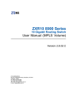
4Motion®
System Manual
Release Version: 3.5
December 2011
P/N 215969
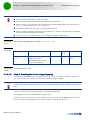
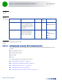
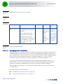
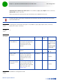
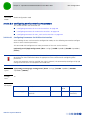
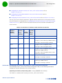
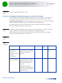
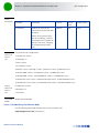
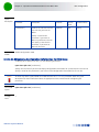
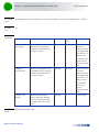
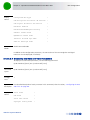
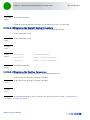
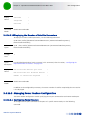
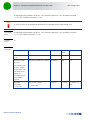
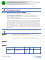
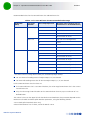
Document History
Document History
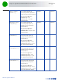
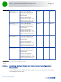
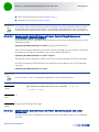
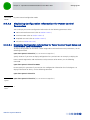
Topic
Description
Date Issued
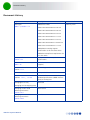
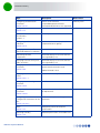
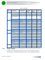
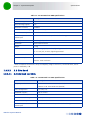
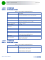
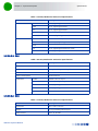
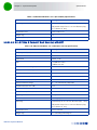
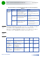
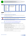
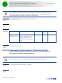
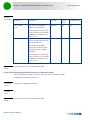
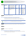
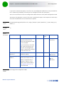
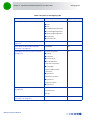
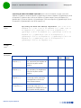
ODU Types
Table 1-3, Section 1.5.3
Added new ODUs:
February 2010
ODU-2300-2400-000N-38-2X2-N-0
ODU-2485-2690-000N-38-2X2-N-0
ODU-2590-2690-000N-38-2x2-N-0
ODU-3345-3400-000N-33-1x1-N-0
ODU-3400-3600-000N-37-2x2-N-0
ODU-3400-3600-000N-37-4x2-BF-N-0
ODU-3650-3700-000N-22-1x1-N-0
Added Beam Forming Support
specifications to all 4x2 ODUs tables.
Added ETSI compliance requirements for
2.5 GHz ODUs.
ODUs Specifications
Section 1.5.3
Updated Power Consumption
specifications
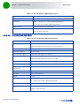
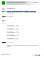
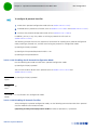
2.3-2.7 GHz DDP Antennas
Table 1-38
Added BS-EDT-DDP-ANT 2.3-2.7 (No RET
support).
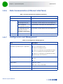
Macro Outdoor Units
Section 1.3.2
New unit types with 2-channels AUs.
Micro Outdoor BTS
New product line.
GPS for Macro BTS
Sections 1.3.7.1, 1.5.10.4
Added details on new GPS receiver,
updated specifications (added Interface
specs) of Timing GPS.
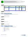
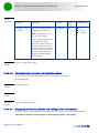
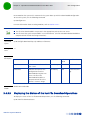
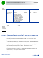
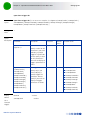
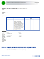
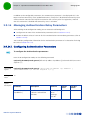
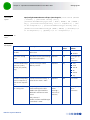
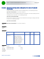
Managing BS Services,
Removed
Managing Service Mapping Rules
Managing the BTS Load
Balancing Parameters
Section 3.4.11
New feature
Managing the BS ASN-GW Load
Balancing Parameters
Section 3.9.25
New feature
4Motion System Manual
ii
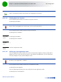
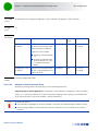
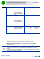
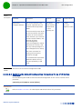
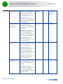
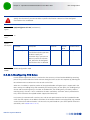
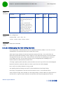
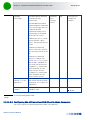
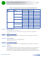
Document History
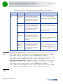
Topic
Description
Date Issued
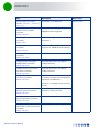
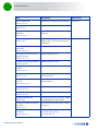
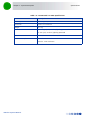
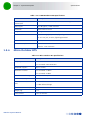
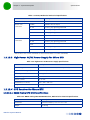
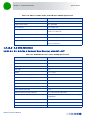
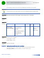
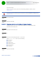
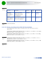
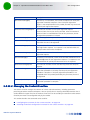
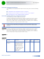
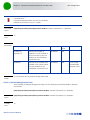
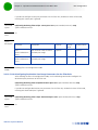
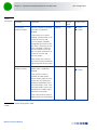
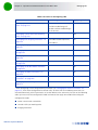
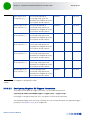
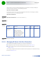
Airframe MIMO Parameters
Sections 3.9.12.2.7, 3.9.12.3.4,
3.9.12.5.7
Removed bcast-msgzone-loc
February 2010
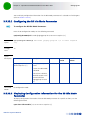
Configuring the Airframe
Downlink Diversity Mode
Parameter
Section 3.9.12.2.3
Added description of supported modes.
Airframe Dynamic Permutations
Parameters
Section 3.9.12
Removed (changed to vendor
parameters)
Configuring Airframe General
Parameters
Section 3.9.12.2.1
Updated value range for ul-duration and
frame-offset. Added nbr-beam-forming.
Configuring Airframe Map Zone
Parameters
Section 3.9.12.2.2
Added RCID-Usage
Configuring Airframe Uplink
Feedback Zone Parameters
Section 3.9.12.2.4
Removed subchannels (changed to
vendor parameter)
Configuring Airframe Downlink
Data Zone Parameters
Section 3.9.12.2.5
Removed subchannels (changed to
vendor parameter)
Configuring Airframe Uplink
Data Zone Parameters
Section 3.9.12.2.6
Removed subchannels-number (changed
to vendor parameter) and startallocation
(obsolete-hard coded to 0).
Added beamForming option
permbase is mandatory when creating a
new BS.
Restoring the Default Values of
Airframe General Parameters
Section 3.9.12.3.1
Added nbr-beam-forming (new
parameter) and frame-offset
Restoring the Default Values of
Airframe Map Zone Parameters
Section 3.9.12.3.2
Added RCID-Usage
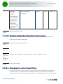
Displaying Configuration
Information for Airframe General
Parameters
Section 3.9.12.5.1
Added NeighborBeamForming
4Motion System Manual
iii
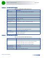
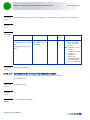
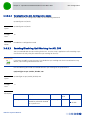
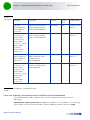
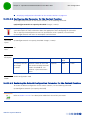
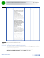
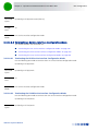
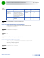
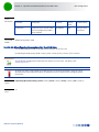
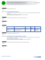
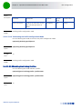
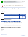
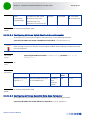
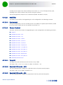
Document History
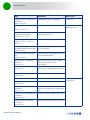
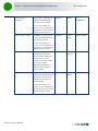
Topic
Description
Date Issued
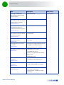
Displaying Configuration
Information for Airframe Map
Zone Parameters
Section 3.9.12.5.2
Added RcidUsage
February 2010
Displaying Configuration
Information for Airframe Uplink
Feedback Zone Parameters
Section 3.9.12.5.4
Removed subchannels
Displaying Configuration
Information for Airframe
Downlink Data Zone Parameters
Section 3.9.12.5.5
Removed subchannels
Displaying Configuration
Information for Airframe Uplink
Data Zone Parameters
Section 3.9.12.5.6
Removed subchannels-number and
startallocation.
Managing BS Feedback
Allocation Parameter
Section 3.9.5
Removed max-cqi (changed to vendor
parameter)
Managing BS Bearer Interface
Parameters
Section 3.9.13
Removed linkusage-hardthrshld and mtu
(changed to vendor parameters).
Managing BS General Parameters
Section 3.9.3
Added dl-def-rate-for data.
Added ASNGWStatus (read-only).
Changed dl-def-rate to
dl-def-for-management and updated
default value.
Added deployment
Configuring Alarm Threshold
Parameters
Section 3.9.20.1
Updated descriptions and defaults of
ul-mednoise and ul-99prcntnoise.
Configuring Power Control
Parameters
Section 3.9.4.2
Changed pusc to target-ni. Updated step
size to 1. Removed cqi-ack-ranging.
Managing Handover Negotiation
at TBS Parameters
Removed. defaultactiontime is obsolete
(calculated automatically),
fastrangingalloc changed to vendor
parameter)
4Motion System Manual
iv
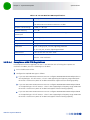
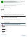
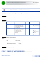
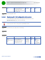
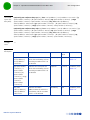
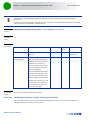
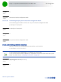
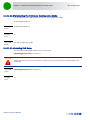
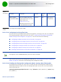
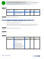
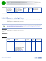
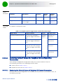
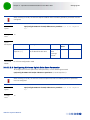
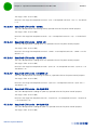
Document History
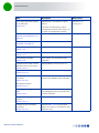
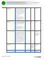
Topic
Description
Date Issued
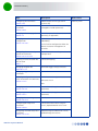
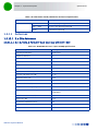
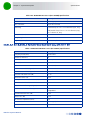
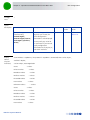
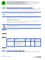
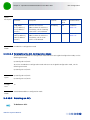
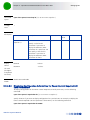
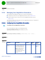
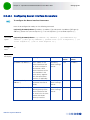
Configuring AU Parameters
Section 3.6.2
Added support for AU type au2x2
(2-ports AU).
February 2010
Managing the BS Idle Mode
Parameters
Section 3.9.23
Removed idle-Mode-ms-initiated-for-ugs
(changed to vendor parameter)
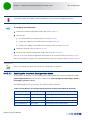
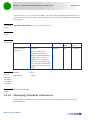
Managing Software Upgrade
Section 3.2
Moved to Operation Chapter (was
previously an Appendix)
Managing AAA Client
Configuration
Section 3.4.12.9.1
Added support for AAA server
redundancy.
Configuring the DHCP Relay
Option 82 Parameters
Section 3.4.12.10.4.4.2
Added new option to Subopt1value and
Subopt2value
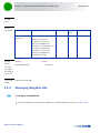
Mapping of Macro Outdoor BTS
AUs to Slot #
Table 3-1
Corrected mapping
Managing Neighbor BSs
Appendix 3.9.9
Removed Trigger Setup parameters.
Managing Trigger Setup
Parameters
Removed
Displaying Configuration and
Status Information for ODU Ports
Section 3.7.2.6
Added new read-only parameters
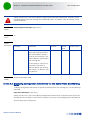
src-intf can be configured to either the
bearer or external-management IP
interface.
odu-status-mask
RSSI
Managing Service Interfaces
Section 3.4.12.8
removed mtu (changed to vendor
parameter)
Configuring IP Interfaces
Section 3.4.2.3
removed mtu (changed to vendor
parameter)
Managing the Hot-Lining Feature
Section 3.4.12.13
New feature.
Configuring BS Keep-Alive
Parameters
Section 3.9.22.1
Corrected Possible Values range of
rtx-cnt, Updated Default of rtx-time.
configuring ASN-GW Keep-Alive
Parameters
Section 3.4.12.14.1
Updated range and default for rtx-cnt,
updated range for rtx-time.
4Motion System Manual
v
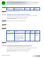
Document History
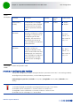
Topic
Description
Date Issued
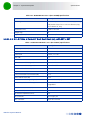
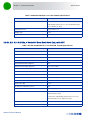
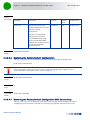
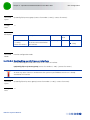
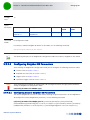
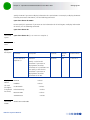
Configuring General
Configuration Parameters for the
GPS
Section 3.4.16.2.2
Updated default value for
HoldoverTimeout
February 2010
Managing the Context Function
Section 3.4.12.4
Updated to reflect the ability to
configure the ms-capacity-threshold
parameter.
Managing the Data Path
Function
Section 3.4.12.3
Updated to reflect the ability to
configure the throughput-threshold
parameter.
Configuring/Displaying the
Daylight Saving Parameters
Sections 3.4.16.2.4,
3.4.16.2.10
New feature
Creating a Sector Association
Entry
Section 3.10.2.1
Updated configuration rules
Sector Connections Schemes
Appendix A
New section, replacing previous Antenna
Configurations section
Configuring Parameters for IP-IP
Service Interface
Section 3.4.12.8.2.1
Updated Description, Presence and
Default Value for srcaddr and dstaddr.
Configuring Parameters for VLAN
Service Interface
Section 3.4.12.8.2.2
Updated Description, Presence and
Default Value for vlan-id and dflt-gw-ip.
Configuring DHCP Server
Parameters
Section 3.4.12.10.4.2.1
Updated default value of opt60.
Specifying DHCP Proxy
Configuration Parameters
Section 3.4.12.10.4.3.1
Updated default value of opt60.
Configuring the DHCP Relay
Parameters
Section 3.4.12.10.4.4.1
Updated Description, Presence and
Default Value of server-addr.
Configuring Classification Rules
Section 3.4.12.11.4
Updated and corrected the sections
related to L2 classifiers.
Managing the Baseband
Bandwidth Parameter
Section 3.9.11
A bandwidth of 7 MHz is not applicable
for ODUs in the 2.x GHz band.
4Motion System Manual
vi
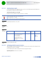
Document History
Topic
Description
Date Issued
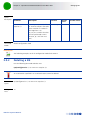
Configuring Authentication
Parameters
Section 3.9.14.1
Alarms associated with
suspendedeapprocthrshld and
maxeaproundsthrshld are not supported
February 2010
Configuring ODU Ports
Section 3.7.2
Tx power resolution updated to 1 dBm
April 2010
Operation and Administration of
the Micro BTS
Chapter 4
New chapter
Configuring Performance Data
Collection
Section 3.4.14
Updated section content, updated
supported counters groups.
Managing MSs for Specific MS
Advanced Mode Data Collection
Removed (feature not supported)
Monitoring Software
Components
Removed (display of real-time counters
not supported by CLI)
Displaying Statistics for Physical
and IP Interfaces
Removed (display of real-time counters
not supported by CLI)
Managing Power Control
Parameters
Section 3.9.4
Removed:
power-control-correction-factor
Displaying the VLAN Translation
Entries
Section 3.4.2.1.7
Updated command syntax
Managing Beam Forming
Parameter
Section 3.9.26
New feature
Configuring Alarm Threshold
Parameters
Section 3.9.20.1
Updated description and default value of
ul-99prcntnoise.
Configuring General
Configuration Parameters for the
GPS
Section 3.4.16.2.2
Added Lassen option to the Type
parameter
ODUs
Section 1.5.3
Updated all power consumption
specifications
Operating Humidity
Section 1.5.9
Updated specifications for outdoor units
4Motion System Manual
Added: allowed-if-level
May 2010
vii
Document History
Topic
Description
Date Issued
Macro Outdoor BTS
Section 1.5.10.2
Updated unit’s dimensions and weights
May 2010
ODUs
Section 1.5.3
Updated weights
Mechanical and Electrical, Macro
Indoor BTS
Section 1.5.10.1
Updated weights of Shelf, AVU, PIU,
NPU, AU
Configuring Logging
Section 3.4.13
Updated severity levels for module level
logging (Alert, Error and Info levels are
supported)
Displaying the Current Log
Destination
Section 3.4.13.1.4
Updated display format
Displaying the Current Status of
Trace Destinations
Section 3.12.1.1.3
Updated display format
Configuring the Unique Identifier
Section 3.4.16.8.1
Updated range for site id
Testing Connectivity to an IP
Interface
Section 3.4.2.3.8
New command (ping test)
Resetting the system
Section 3.3.2.1
Updated command syntax and
command mode
Configuring Parameters for the
PHS Rule
Section 3.4.12.12.2
Corrected definition for verify (in
Possible Values)
Displaying System-level Logs
Section 3.4.13.1.3
Updated command syntax
Configuring the Position
Section 3.4.16.2.5
Updated command syntax
Managing Neighbor BSs,
Section 3.9.9
In General: Removed srvcsupport, added
bsNeighborBsDlDataMIMOMode
Configuring Feedback Allocation
Parameter
Section 3.9.5.1
In current release actual value of ir-cdma
is always 2
Configuring Airframe MIMO
Parameters
Section 3.9.12.2.7
Limitations in functionality of
first-zone-min-size and
first-zone-max-size
4Motion System Manual
June 2010
viii
Document History
Topic
Description
Date Issued
Configuring Airframe Map Zone
Parameters
Section 3.9.12.2.2
Updated description of majorgrps.
June 2010
ODU-3475-3675-000N-37-2x2-N
-0
Table 1-3, Table 1-13
New ODU
Version 3.0.10
December 2010
Specifying Service Flow
Configuration Parameters
Section 3.4.12.11.3.3.2
Updated Possible Value range for
media-type (up to 15)
General Neighbor BS Parameters
Sections 3.9.9.2.1, 3.9.9.3.1,
3.9.9.7.1
Added: sound-symbol
Enabling/Disabling an ASN-GW
Load Balancing Pool (Macro BTS)
Section 3.9.25.2
Updated description (configuration rules)
of asn-gw-pool-2
ASN-GW Load Balancing (Micro
BTS)
Section 4.7.2.7.4
Updated description (configuration rules
for the Secondary Pool)
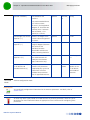
Macro BTS AU - Configuring
Properties
Section 3.6.2.1
New option (rxOnly) for port-1-power,
port-2-power, port-3-power,
port-4-power.
Micro BTS AU Control
Section 4.8.1.2
New option (rxOnly) for Shutdown
Power Port 1 and Shutdown Power Port
2.
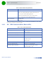
Managing BS General Parameters
Section 3.9.3
New parameter: max-sub-burst-mode
Legal Rights
Added Industry Canada Statement
Standards Compliance, General
Section 1.5.8
Added RSS-192, RSS-197
AU - ODU Communication
(Macro BTS)
Section 1.5.5
Correction: changed Maximum IF cable
Return Loss to Minimum IF cable Return
Loss
Configuring General Neighbor BS
Parameters
Section 3.9.9.2.1
Updated range for frequency parameter
Configuring the RF Frequency
Parameters
Section 3.9.10.1
Updated range for frequency parameter
4Motion System Manual
Version 3.0.10
January 2011
ix
Document History
Topic
Description
Date Issued
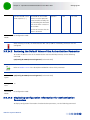
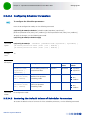
Accessing the Monitor Program
of the Micro BTS
Section 4.2.1
Monitor port is not usable in current
release.
Version 3.0.10
January 2011
“FCC and Industry Canada
Radiation Hazard Warning” on
page xviii
Added Industry Canada
“Antenna Compliance
Statement” on page xviii
New section
Antenna - general description
Section 1.3.6
Updated
Antennas - specifications
Section 1.5.11
Updated, added new antennas
Downgrading procedure
Section 3.2.4
New section, new command (allow
migration)
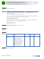
Configuring the Power Control
Required C/N Level Parameters
Section 3.9.4.2.2
Updated default value of ack to 12
Required C/N Levels - ACK
Section 4.7.2.4.2.
Updated default value to 12
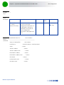
Configuring Airframe General
Parameters
Section 3.9.12.2.1
Added details on DL:UL ratio as a
function of bandwidth and ul-duration.
Full details on connecting via local
management interface (192.168.0.1) or
via external management interface.
February 2011
July 2011
Total Uplink Duration
Section 4.7.2.6.5
Managing QoS Classification
Rules
Section 3.4.8.2
Added rule (in two places): Default
(pre-configured) QoS classification rules
cannot be deleted
Assigning an IP address to an
interface
Section 3.4.2.3.3
Updated configuration rules
Configuring Airframe MIMO
Parameters
Section 3.9.12.2.7
Updated Table 3-34 (Calculating the
Upper Limit Value (Y) for Minimum and
Maximum Size)
4Motion System Manual
x
Document History
Topic
Description
Date Issued
First Zone
Section 4.7.2.2.3
Updated Table 4-2 (Calculating the
Upper Limit Value (Y) for Minimum and
Maximum Size)
July 2011
Configuring Static Routes
Section 3.4.9
Added a caution notes related to routes
for SNMP Trap Managers, Log server and
Software Upgrade TFTP server created by
a management system.
Configuring the Trap Manager
Section 3.4.15.2
Added note -recommended to manage
Trap Manager IP Address from the
management system.
Enabling System-level Logging
Section 3.4.13.1.1
Added note -recommended to manage
Log TFTP Server IP Address from the
management system.
Upgrading the NPU
Section 3.2.2
Added note -recommended to manage
TFTP Server IP Address the management
system
Upgrading the AU
Section 3.2.3
Added note -recommended to manage
TFTP Server IP Address from the
management system
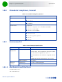
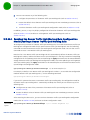
Commissioning - Completing the
Site Configuration Using
AlvariSTAR
Section 2.1.2
Updated to reflect changes related to
automatic management of IP routing.
Commissioning - Site Page General Tab
Section 2.1.2.2.1
Reset required to apply a change in ASN
Topology.
Commissioning - Equipment External - GPS
Section 2.1.2.4.4
Updated default GPS Type to None
Commissioning - SFA Page
-Classification Rules Tab
Section 2.1.2.5.3
Added note-not applicable if service
profiles, service flows and classification
rules are defined in AAA server.
Commissioning - Service Profiles
Section 2.1.2.5.4
Added note-not applicable if service
profiles, service flows and classification
rules are defined in AAA server.
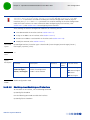
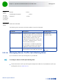
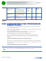
NPU Software Upgrade - Step 2:
Triggering Software Download
Section 3.2.2.1.2
Added more possible reasons for error
4Motion System Manual
xi
Document History
Topic
Description
Date Issued
AU Software Upgrade - Step 2:
Downloading the AU Image to
the NPU Flash
Section 3.2.3.1.2
Added more possible reasons for error
July 2011
Micro BTS Unit Control
Section 4.5.3
Reset option removed (supported in
ShutDown Operation)
Tracing
Removed: Section 3.12.1.
Updated: Sections 3.3.1,
3.3.2.1, 3.4.13, 3.4.13.1.1,
3.4.13.1.3, 3.4.13.1.5,
3.4.13.1.6, 3.4.16.2.3, 3.11.2,
Tracing can be managed only by the
vendor
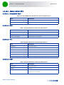
3.3 GHz Band 1x1 ODUs
Section 1.5.3.3.1
Updated Maximum Tx Power
Micro Outdoor BTS
Section 1.5.4
Updated Maximum Tx Power and
Bandwidth Support.
Added note on ETSI compliance
Interpreting the Command
Syntax
Section 3.1.4
Updated syntax for the command
pm-group enable npu.
Configuring Performance Data
Collection
Section 3.4.14
Updated: Added AAAClient to NPU
Counters
Configuring the External Ether
type
Section 3.4.2.2.1
Updated default value to 8100
Managing Authentication
Parameters
Section 3.9.14
Removed suspendedeapprocthrshld,
maxeaproundsthrshld.
BS Authentication parameters
(Micro)
Section 4.7.2.7.2
Removed: Thresholds - Suspended EAP
Process, Threshold - Maximum EAP
Rounds.
Managing Service Groups
Section 3.4.12.10
Added support for a new type of service
group: VPLS Hub and Spoke.
Added Display Format
Total number of service groups updated
to 80 (total number of IP and VPWS
service groups is limited to a maximum
of 10).
4Motion System Manual
xii
Document History
Topic
Description
Date Issued
Managing Service Interfaces
Section 3.4.12.8
Added support for a new type of service
interface: VPLS Trunk.
July 2011
Total number of service interfaces
updated to 80 (total number of IP-IP,
VLAN and QinQ service interfaces is
limited to a maximum of 10).
Configuring the Parameter for
the Data Path Function
Section 3.4.12.3.1
Updated default value of
throughput-threshold to 500.
Configuring the Parameter for
the Context Function
Section 3.4.12.4.1
Updated default value of
ms-capacity-threshold to 3000
Configuring Parameters for VLAN
Service Interface
Section 3.4.12.8.2.2
Updated configuration rules for vlan-id.
Configuring Parameter for QinQ
Service Interface
Section 3.4.12.8.2.3
Updated configuration rules for vlan-id.
Configuring/Modifying the VLAN
ID for an IP Interface
Section 3.4.2.3.5
Updated configuration rules for VLAN
IDs of IP interfaces.
Configuring the AU Maintenance
VLAN ID
Section 3.4.3.1
Updated configuration rules for AU
Maintenance VLAN ID
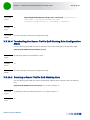
Managing Alarm Threshold
Parameters
Section 3.9.20
Removed: Be-exc-dl-drop-thr,
rt-exc-dl-drop-thr, nrt-exc-dl-drop-thr,
ugs-exc-dl-drop-thr, ert-exc-dl-drop-thr
BS Management parameters
(Micro)
Section 4.7.2.8
Removed: DL Dropped Packets Ratio
Thresholds
Configuring Airframe General
Parameters
Section 3.9.12.2.1
Updated supported values for
ul-duration (Total Uplink Duration)
Total Uplink Duration (Micro)
Sections 4.7.1.7, 4.7.2.6.5
4Motion System Manual
xiii
Document History
Topic
Description
Date Issued
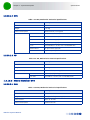
Configuring DHCP Server
Parameters
Section 3.4.12.10.4.2.1
Updated default value and improved
description for opt60.
July 2011
Specifying DHCP Proxy
Configuration Parameters
Section 3.4.12.10.4.3.1
Configuring Service Flows
Section 3.4.12.11.3.3
Updated configuration rules for grp-alias
Configuring Uplink/Downlink
Classification Rule Names
Section 3.4.12.11.3.3.4
Updated configuration rules for
rulename
Configuring Port Monitoring
Section 3.12.1
Updated port details for Interface IDs
0/5, 0/6, 0/7.
Enabling/Disabling an ASN-GW
Load Balancing Pool
Section 3.9.25.1
Default value of asn-gw-pool-1 and
asn-gw-pool-1 is Disable.
ASN-GW Load Balancing-Pools
Availability
Section 4.7.2.7.4.1
The default Status for both pools is
Disabled.
Specifying the port speed
Section 3.4.2.1.2.4
The default for all ports (including Data
and CSCD ports) is 100 Mbps
Managing BS General Parameters
Section 3.9.3
New parameter: legacy-asngw-mode
(Legacy AsnGw Mode)
BS General (Micro)
Section 4.7.2.1
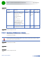
Glossary
Updated (added RCID, VPLS, VPWS
Environmental Specifications
Section 1.5.9
Updated temperature range for Macro
Outdoor BTS units
About This Manual
Updated content of the manual
Configuring the Local Switching
Parameter of a VPLS Service
Group
Section 3.4.12.10.8.4
Added parameters
Privilege Levels
Section 3.1.5.5
Improved
Managing Users and Privileges
Section 3.1.6
Corrected and improved
4Motion System Manual
September 2011
xiv
Document History
Topic
Description
Date Issued
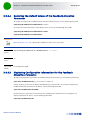
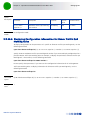
Terminating the Session
Section 3.1.8.3
New section
September 2011
Handling Traffic in a VPLS Hub
and Spoke Service Group
Section 3.4.12.10.10
New section that provides details on
handling uplink/downlink traffic in VPLS
Hub and Spoke services, and describes
how to view relevant MAC Address
tables information and how to clear
these tables.
Configuring the DHCP Server
Section 3.4.12.10.4.2
Updated default value of Opt60
4Motion System Manual
xv
Legal Rights
Legal Rights
© Copyright 2011 Alvarion Ltd. All rights reserved.
The material contained herein is proprietary, privileged, and confidential and owned by Alvarion or its
third party licensors. No disclosure thereof shall be made to third parties without the express written
permission of Alvarion Ltd.
Alvarion Ltd. reserves the right to alter the equipment specifications and descriptions in this publication
without prior notice. No part of this publication shall be deemed to be part of any contract or warranty
unless specifically incorporated by reference into such contract or warranty.
Trade Names
Alvarion®, BreezeCOM®, WALKair®, WALKnet®, BreezeNET®, BreezeACCESS®, BreezeMAX®,
BreezeLITE®, 4Motion®, and/or other products and/or services referenced here in are either registered
trademarks, trademarks or service marks of Alvarion Ltd.
All other names are or may be the trademarks of their respective owners.
“WiMAX Forum” is a registered trademark of the WiMAX Forum. “WiMAX,” the WiMAX Forum logo,
“WiMAX Forum Certified”, and the WiMAX Forum Certified logo are trademarks of the WiMAX Forum.
Statement of Conditions
The information contained in this manual is subject to change without notice. Alvarion Ltd. shall not be
liable for errors contained herein or for incidental or consequential damages in connection with the
furnishing, performance, or use of this manual or equipment supplied with it.
Warranties and Disclaimers
All Alvarion Ltd. (“Alvarion“) products purchased from Alvarion or through any of Alvarion's authorized
resellers are subject to the following warranty and product liability terms and conditions.
Exclusive Warranty
(a) Alvarion warrants that the Product hardware it supplies and the tangible media on which any
software is installed, under normal use and conditions, will be free from significant defects in materials
and workmanship for a period of fourteen (14) months from the date of shipment of a given Product to
Purchaser (the "Warranty Period"). Alvarion will, at its sole option and as Purchaser's sole remedy, repair
or replace any defective Product in accordance with Alvarion' standard R&R procedure.
(b) With respect to the Firmware, Alvarion warrants the correct functionality according to the attached
documentation, for a period of fourteen (14) month from invoice date (the "Warranty Period")". During
the Warranty Period, Alvarion may release to its Customers firmware updates, which include additional
performance improvements and/or bug fixes, upon availability (the "Warranty"). Bug fixes, temporary
patches and/or workarounds may be supplied as Firmware updates.
Additional hardware, if required, to install or use Firmware updates must be purchased by the Customer.
Alvarion will be obligated to support solely the two (2) most recent Software major releases.
ALVARION SHALL NOT BE LIABLE UNDER THIS WARRANTY IF ITS TESTING AND EXAMINATION DISCLOSE
THAT THE ALLEGED DEFECT IN THE PRODUCT DOES NOT EXIST OR WAS CAUSED BY PURCHASER'S OR
ANY THIRD PERSON'S MISUSE, NEGLIGENCE, IMPROPER INSTALLATION OR IMPROPER TESTING,
UNAUTHORIZED ATTEMPTS TO REPAIR, OR ANY OTHER CAUSE BEYOND THE RANGE OF THE INTENDED
USE, OR BY ACCIDENT, FIRE, LIGHTNING OR OTHER HAZARD.
4Motion System Manual
xvi
Legal Rights
Disclaimer
(a) The Software is sold on an "AS IS" basis. Alvarion, its affiliates or its licensors MAKE NO
WARRANTIES, WHATSOEVER, WHETHER EXPRESS OR IMPLIED, WITH RESPECT TO THE SOFTWARE AND
THE ACCOMPANYING DOCUMENTATION. ALVARION SPECIFICALLY DISCLAIMS ALL IMPLIED
WARRANTIES OF MERCHANTABILITY AND FITNESS FOR A PARTICULAR PURPOSE AND
NON-INFRINGEMENT WITH RESPECT TO THE SOFTWARE. UNITS OF PRODUCT (INCLUDING ALL THE
SOFTWARE) DELIVERED TO PURCHASER HEREUNDER ARE NOT FAULT-TOLERANT AND ARE NOT
DESIGNED, MANUFACTURED OR INTENDED FOR USE OR RESALE IN APPLICATIONS WHERE THE
FAILURE, MALFUNCTION OR INACCURACY OF PRODUCTS CARRIES A RISK OF DEATH OR BODILY
INJURY OR SEVERE PHYSICAL OR ENVIRONMENTAL DAMAGE ("HIGH RISK ACTIVITIES"). HIGH RISK
ACTIVITIES MAY INCLUDE, BUT ARE NOT LIMITED TO, USE AS PART OF ON-LINE CONTROL SYSTEMS IN
HAZARDOUS ENVIRONMENTS REQUIRING FAIL-SAFE PERFORMANCE, SUCH AS IN THE OPERATION OF
NUCLEAR FACILITIES, AIRCRAFT NAVIGATION OR COMMUNICATION SYSTEMS, AIR TRAFFIC CONTROL,
LIFE SUPPORT MACHINES, WEAPONS SYSTEMS OR OTHER APPLICATIONS REPRESENTING A SIMILAR
DEGREE OF POTENTIAL HAZARD. ALVARION SPECIFICALLY DISCLAIMS ANY EXPRESS OR IMPLIED
WARRANTY OF FITNESS FOR HIGH RISK ACTIVITIES.
(b) PURCHASER'S SOLE REMEDY FOR BREACH OF THE EXPRESS WARRANTIES ABOVE SHALL BE
REPLACEMENT OR REFUND OF THE PURCHASE PRICE AS SPECIFIED ABOVE, AT ALVARION'S OPTION.
TO THE FULLEST EXTENT ALLOWED BY LAW, THE WARRANTIES AND REMEDIES SET FORTH IN THIS
AGREEMENT ARE EXCLUSIVE AND IN LIEU OF ALL OTHER WARRANTIES OR CONDITIONS, EXPRESS OR
IMPLIED, EITHER IN FACT OR BY OPERATION OF LAW, STATUTORY OR OTHERWISE, INCLUDING BUT
NOT LIMITED TO WARRANTIES, TERMS OR CONDITIONS OF MERCHANTABILITY, FITNESS FOR A
PARTICULAR PURPOSE, SATISFACTORY QUALITY, CORRESPONDENCE WITH DESCRIPTION,
NON-INFRINGEMENT, AND ACCURACY OF INFORMATION GENERATED. ALL OF WHICH ARE EXPRESSLY
DISCLAIMED. ALVARION' WARRANTIES HEREIN RUN ONLY TO PURCHASER, AND ARE NOT EXTENDED
TO ANY THIRD PARTIES. ALVARION NEITHER ASSUMES NOR AUTHORIZES ANY OTHER PERSON TO
ASSUME FOR IT ANY OTHER LIABILITY IN CONNECTION WITH THE SALE, INSTALLATION, MAINTENANCE
OR USE OF ITS PRODUCTS.
Limitation of Liability
(a) ALVARION SHALL NOT BE LIABLE TO THE PURCHASER OR TO ANY THIRD PARTY, FOR ANY LOSS OF
PROFITS, LOSS OF USE, INTERRUPTION OF BUSINESS OR FOR ANY INDIRECT, SPECIAL, INCIDENTAL,
PUNITIVE OR CONSEQUENTIAL DAMAGES OF ANY KIND, WHETHER ARISING UNDER BREACH OF
CONTRACT, TORT (INCLUDING NEGLIGENCE), STRICT LIABILITY OR OTHERWISE AND WHETHER BASED
ON THIS AGREEMENT OR OTHERWISE, EVEN IF ADVISED OF THE POSSIBILITY OF SUCH DAMAGES.
(b) TO THE EXTENT PERMITTED BY APPLICABLE LAW, IN NO EVENT SHALL THE LIABILITY FOR DAMAGES
HEREUNDER OF ALVARION OR ITS EMPLOYEES OR AGENTS EXCEED THE PURCHASE PRICE PAID FOR
THE PRODUCT BY PURCHASER, NOR SHALL THE AGGREGATE LIABILITY FOR DAMAGES TO ALL PARTIES
REGARDING ANY PRODUCT EXCEED THE PURCHASE PRICE PAID FOR THAT PRODUCT BY THAT PARTY
(EXCEPT IN THE CASE OF A BREACH OF A PARTY'S CONFIDENTIALITY OBLIGATIONS).
Radio Frequency Interference Statement
The Base Transceiver Station (BTS) equipment has been tested and found to comply with the limits for a
class A digital device, pursuant to ETSI EN 301 489-1 rules and Part 15 of the FCC Rules. These limits are
designed to provide reasonable protection against harmful interference when the equipment is operated
in commercial, business and industrial environments. This equipment generates, uses, and can radiate
radio frequency energy and, if not installed and used in accordance with the instruction manual, may
cause harmful interference to radio communications. Operation of this equipment in a residential area is
likely to cause harmful interference in which case the user will be required to correct the interference at
the user's own expense.
4Motion System Manual
xvii
Legal Rights
FCC and Industry Canada Radiation Hazard Warning
To comply with Industry Canada exposure requirements, and FCC RF exposure requirements in Section
1.1307 and 2.1091 of FCC Rules, the antenna used for this transmitter must be fixed-mounted on
outdoor permanent structures with a separation distance of at least 205 cm from all persons.
Industry Canada Statement
Users can obtain Canadian information on RF exposure and compliance from the
Canadian Representative:
David MacDonald
[email protected]
Antenna Compliance Statement
This device has been designed to operate with the antennas listed in Section 1.5.11, and having a
maximum gain of 18 dBi. Antennas not included in this list or having a gain greater than 18 dBi are
strictly prohibited for use with this device.
The required antenna impedance is 50 ohms. To reduce potential radio interference to other users, the
antenna type and its gain should be so chosen that the Equivalent Isotropically Radiated Power (EIRP) is
not more than that permitted for successful communication.
R&TTE Compliance Statement
This equipment complies with the appropriate essential requirements of Article 3 of the R&TTE Directive
1999/5/EC.
Safety Considerations - General
For the following safety considerations, "Instrument" means the BreezeMAX units' components and
their cables.
Grounding
BTS chassis, Power Feeders and Outdoor Units are required to be bonded to protective grounding using
the bonding stud or screw provided with each unit.
Safety Considerations - DC Powered Equipment (BTS & Power Feeder)
Caution
Attention
Risk of electric shock and energy hazard.Disconnecting
one Power Interface Unit (PIU) disconnects only one PIU
module. To isolate the BTS completely, disconnect both
PIUs
Risque de décharge électrique et d'electrocution. La
déconnection d'un seul module d'alimentation (PIU)
n'isole pas complètement la Station de Base. Pour cela,
il faut impérativement débrancher les deux modules
d'alimentation (PIU).
Restricted Access Area: The DC powered equipment should only be installed in a Restricted Access
Area.
Installation Codes: The equipment must be installed according to the latest edition of the country
national electrical codes. For North America, equipment must be installed in accordance with the US
National Electrical Code and the Canadian Electrical Code.
4Motion System Manual
xviii
Legal Rights
Overcurrent Protection: A readily accessible Listed branch circuit overcurrent protective device, rated
60A for the Macro BTS or 20A for the Power Feeder or 10A for the Micro BTS, must be incorporated in
the building wiring.
CAUTION: This equipment is designed to permit connection between the earthed conductor of the DC
supply circuit and the grounding conductor at the equipment. See installation instructions.
The equipment must be connected directly to the DC Supply System grounding electrode conductor.
All equipment in the immediate vicinity must be grounded in the same way, and not be grounded
elsewhere.
The DC supply system is to be local, i.e. within the same premises as the equipment.
There shall be no disconnect device between the grounded circuit conductor of the DC source
(return) and the point of connection of the grounding electrode conductor.
Lithium Battery
The battery on the NPU card is not intended for replacement.
Caution
To avoid electrical shock, do not perform any servicing unless you are qualified to do so.
Line Voltage
Before connecting this instrument to the power line, make sure that the voltage of the power source
matches the requirements of the instrument.
Radio
The instrument transmits radio energy during normal operation. To avoid possible harmful exposure to
this energy, do not stand or work for extended periods of time in front of its antenna. The long-term
characteristics or the possible physiological effects of radio frequency electromagnetic fields have not
been yet fully investigated.
Outdoor Units and Antennas Installation and Grounding
Ensure that outdoor units, antennas and supporting structures are properly installed to eliminate any
physical hazard to either people or property. Make sure that the installation of the outdoor unit, antenna
and cables is performed in accordance with all relevant national and local building and safety codes.
Even where grounding is not mandatory according to applicable regulation and national codes, it is
highly recommended to ensure that the outdoor unit and the antenna mast (when using external
antenna) are grounded and suitable lightning protection devices are used so as to provide protection
against voltage surges and static charges. In any event, Alvarion is not liable for any injury, damage or
regulation violations associated with or caused by installation, grounding or lightning protection.
4Motion System Manual
xix
Legal Rights
Disposal of Electronic and Electrical Waste
Disposal of Electronic and Electrical Waste
Pursuant to the WEEE EU Directive electronic and electrical waste must not be disposed of with unsorted waste.
Please contact your local recycling authority for disposal of this product.
4Motion System Manual
xx
Important Notice
Important Notice
This user manual is delivered subject to the following conditions and restrictions:
This manual contains proprietary information belonging to Alvarion Ltd. Such information is supplied
solely for the purpose of assisting properly authorized users of the respective Alvarion products.
No part of its contents may be used for any other purpose, disclosed to any person or firm or
reproduced by any means, electronic and mechanical, without the express prior written permission of
Alvarion Ltd.
The text and graphics are for the purpose of illustration and reference only. The specifications on
which they are based are subject to change without notice.
The software described in this document is furnished under a license. The software may be used or
copied only in accordance with the terms of that license.
Information in this document is subject to change without notice. Corporate and individual names
and data used in examples herein are fictitious unless otherwise noted.
Alvarion Ltd. reserves the right to alter the equipment specifications and descriptions in this
publication without prior notice. No part of this publication shall be deemed to be part of any
contract or warranty unless specifically incorporated by reference into such contract or warranty.
The information contained herein is merely descriptive in nature, and does not constitute an offer for
the sale of the product described herein.
Any changes or modifications of equipment, including opening of the equipment not expressly
approved by Alvarion Ltd. will void equipment warranty and any repair thereafter shall be charged for.
It could also void the user's authority to operate the equipment.
Some of the equipment provided by Alvarion and specified in this manual, is manufactured and
warranted by third parties. All such equipment must be installed and handled in full compliance with the
instructions provided by such manufacturers as attached to this manual or provided thereafter by
Alvarion or the manufacturers. Non-compliance with such instructions may result in serious damage
and/or bodily harm and/or void the user's authority to operate the equipment and/or revoke the
warranty provided by such manufacturer.
4Motion System Manual
xxi
About This Manual
About This Manual
This manual describes the 4Motion solution, and details how to install, operate and manage the BTS
system components.
This manual is intended for technicians responsible for installing, setting and operating the 4Motion BTS
equipment, and for system administrators responsible for managing the system.
This manual contains the following chapters and appendices:
Chapter 1 - System description: Describes the 4Motion BTS and its components.
Chapter 2 - Commissioning: Describes how to configure basic parameters and validate units'
operation.
Chapter 3 - Operation and Administration of the Macro BTS: Describes how to use the
Command Line Interface (CLI) for configuring parameters, checking system status and monitoring
performance of Macro BTS units.
Chapter 4 - Operation and Administration of the Micro BTS: Describes how to use the Monitor
program for configuring parameters, checking system status and monitoring performance of Micro
BTS units.
Appendix A - Antenna Configurations: Describes the proposed antenna configurations that
support the different available diversity scenarios.
Glossary: A listing of commonly used terms.
4Motion System Manual
xxii
Contents
Contents
Chapter 1 - System Description ............................................................................. 1
1.1 About WiMAX .......................................................................................................2
1.2 4Motion Solution .................................................................................................3
1.2.1
4Motion Solution Highlights ................................................................................ 3
1.2.2
WiMAX Network Reference Model....................................................................... 4
1.3 The Base Transceiver Station..............................................................................11
1.3.1
The Indoor Macro BTS........................................................................................ 11
1.3.2
The Macro Outdoor BTS..................................................................................... 16
1.3.3
The Outdoor Micro BTS...................................................................................... 17
1.3.4
ODUs for Macro (Indoor/Outdoor) BTS.............................................................. 17
1.3.5
Power Feeder .................................................................................................... 18
1.3.6
Antenna............................................................................................................. 19
1.3.7
GPS .................................................................................................................... 19
1.4 Element Management Systems ...........................................................................21
1.4.1
AlvariSTAR ......................................................................................................... 21
1.5 Specifications ....................................................................................................22
1.5.1
Modem & Radio ................................................................................................. 22
1.5.2
Sensitivity (per channel)*.................................................................................. 22
1.5.3
ODUs ................................................................................................................. 23
1.5.4
Micro Outdoor BTS ............................................................................................ 32
1.5.5
AU - ODU Communication (Macro BTS).............................................................. 33
1.5.6
Data Communication (Ethernet Interfaces)....................................................... 34
1.5.7
Configuration and Management ........................................................................ 34
1.5.8
Standards Compliance, General ......................................................................... 35
1.5.9
Environmental ................................................................................................... 35
1.5.10 Mechanical and Electrical................................................................................... 35
1.5.11 Antennas ........................................................................................................... 41
Chapter 2 - Commissioning .................................................................................. 52
2.1 Commissioning of the Macro BTS ........................................................................53
2.1.1
Initial NPU Configuration ................................................................................... 53
4Motion System Manual
xxiii
Contents
2.1.2
Completing the Site Configuration Using AlvariSTAR......................................... 56
2.2 Commissioning of the Micro BTS.........................................................................64
2.2.1
Introduction....................................................................................................... 64
2.2.2
Configuring Parameters Required for Management Connectivity...................... 64
2.2.3
Activating the Unit............................................................................................. 65
Chapter 3 - Operation and Administration of the Macro BTS ................................ 68
3.1 Using the Command Line Interface .....................................................................69
3.1.1
Managing the Macro Outdoor BTS..................................................................... 69
3.1.2
Accessing the CLI............................................................................................... 71
3.1.3
Command Modes ............................................................................................... 73
3.1.4
Interpreting the Command Syntax..................................................................... 74
3.1.5
Using the CLI...................................................................................................... 75
3.1.6
Managing Users and Privileges .......................................................................... 78
3.1.7
Managing Secure Shell (SSH) Parameters.......................................................... 87
3.1.8
Managing the Session........................................................................................ 89
3.2 Managing Software Upgrade ...............................................................................95
3.2.1
Before You Start................................................................................................ 95
3.2.2
Upgrading the NPU ............................................................................................ 95
3.2.3
Upgrading the AU ............................................................................................ 101
3.2.4
Downgrading the BTS ...................................................................................... 112
3.3 Shutting Down/Resetting the System ...............................................................114
3.3.1
Shutting Down the System.............................................................................. 114
3.3.2
Managing System Reset .................................................................................. 115
3.4 NPU Configuration............................................................................................117
3.4.1
Managing the IP Connectivity Mode ................................................................ 117
3.4.2
Configuring Physical and IP Interfaces............................................................. 120
3.4.3
Managing the AU Maintenance VLAN ID .......................................................... 146
3.4.4
Managing the NPU Boot Mode......................................................................... 147
3.4.5
Managing the 4Motion Configuration File ....................................................... 150
3.4.6
Batch-processing of CLI Commands ................................................................ 159
3.4.7
Configuring the CPU......................................................................................... 161
3.4.8
Configuring QoS Marking Rules ....................................................................... 166
3.4.9
Configuring Static Routes................................................................................ 180
3.4.10 Configuring ACLs.............................................................................................. 184
3.4.11 Managing the BTS Load Balancing Parameters................................................ 213
4Motion System Manual
xxiv
Contents
3.4.12 Configuring the ASN-GW Functionality ............................................................ 216
3.4.13 Configuring Logging......................................................................................... 373
3.4.14 Configuring Performance Data Collection........................................................ 388
3.4.15 Configuring the SNMP/Trap Manager............................................................... 391
3.4.16 Configuring the 4Motion Shelf ........................................................................ 398
3.5 Managing MS in ASN-GW ..................................................................................432
3.5.1
Manual MS De-registration .............................................................................. 432
3.5.2
Displaying MS Information............................................................................... 433
3.6 Managing AUs ..................................................................................................436
3.6.1
Enabling the AU Configuration Mode\Creating an AU Object .......................... 436
3.6.2
Configuring AU Parameters ............................................................................. 437
3.6.3
Restoring Default Values for AU Configuration Parameters............................ 441
3.6.4
Terminating the AU Configuration Mode ......................................................... 443
3.6.5
Deleting an AU Object ..................................................................................... 444
3.6.6
Displaying Configuration and Status Information for AU Parameters ............. 445
3.7 Managing ODUs ................................................................................................450
3.7.1
Configuring ODUs ............................................................................................ 450
3.7.2
Configuring ODU Ports..................................................................................... 456
3.8 Managing Antennas ..........................................................................................464
3.8.1
Enabling the Antenna Configuration Mode\Creating an Antenna.................... 464
3.8.2
Configuring Antenna Parameters .................................................................... 465
3.8.3
Restoring Default Values for Antenna Parameters ......................................... 468
3.8.4
Terminating the Antenna Configuration Mode ................................................ 468
3.8.5
Deleting an Antenna........................................................................................ 469
3.8.6
Displaying Configuration Information for Antennas........................................ 469
3.9 Managing BSs ...................................................................................................472
3.9.1
Enabling the BS Configuration Mode\Creating a BS Object ............................. 475
3.9.2
Deleting a BS ................................................................................................... 476
3.9.3
Managing BS General Parameters.................................................................... 477
3.9.4
Managing Power Control Levels....................................................................... 485
3.9.5
Managing BS Feedback Allocation Parameter.................................................. 498
3.9.6
Managing Neighbor Advertisement Parameters .............................................. 500
3.9.7
Managing Triggers Parameters ........................................................................ 503
3.9.8
Managing Scan Negotiation Parameters.......................................................... 507
3.9.9
Managing Neighbor BSs ................................................................................... 509
3.9.10 Managing the RF Frequency Parameter........................................................... 532
4Motion System Manual
xxv
Contents
3.9.11 Managing the Baseband Bandwidth Parameter............................................... 535
3.9.12 Managing Airframe Structure Parameters ....................................................... 538
3.9.13 Managing BS Bearer Interface Parameters ...................................................... 564
3.9.14 Managing Authentication Relay Parameters.................................................... 568
3.9.15 Displaying Status Information for Handover Control Parameters ................... 571
3.9.16 Managing Bearer Traffic QoS Marking Rules.................................................... 572
3.9.17 Managing Control Traffic QoS Marking Rules .................................................. 580
3.9.18 Managing ID-IP Mapping Parameters ............................................................... 588
3.9.19 Managing Ranging Parameters ........................................................................ 591
3.9.20 Managing Alarm Threshold Parameters ........................................................... 595
3.9.21 Managing BS Reserved Parameters ................................................................. 599
3.9.22 Managing the BS Keep-Alive Functionality ...................................................... 599
3.9.23 Managing the BS Idle Mode Parameters .......................................................... 602
3.9.24 Managing Scheduler Parameters ..................................................................... 604
3.9.25 Managing the BS ASN-GW Load Balancing Parameters ................................... 608
3.9.26 Managing Beam Forming Parameter................................................................ 612
3.10 Managing Sectors ...........................................................................................615
3.10.1 Configuring Sector Parameters........................................................................ 615
3.10.2 Configuring Sector Association Entries ........................................................... 623
3.11 Monitoring HW and SW Components ...............................................................628
3.11.1 Monitoring Hardware Components.................................................................. 628
3.11.2 Displaying System Files ................................................................................... 634
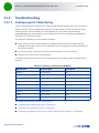
3.12 Troubleshooting .............................................................................................636
3.12.1 Configuring Port Monitoring ............................................................................ 636
Chapter 4 - Operation and Administration of the Micro BTS ...............................642
4.1 Micro BTS System Management ........................................................................643
4.2 The Monitor Program........................................................................................644
4.2.1
Accessing the Monitor Program....................................................................... 644
4.2.2
Using the Monitor Program ............................................................................. 645
4.3 IP Addresses Configuration...............................................................................646
4.3.1
IP Address Configuration Restrictions ............................................................. 646
4.3.2
IP Subnets........................................................................................................ 646
4.4 The Main Menu.................................................................................................647
4.5 BTS Menu.........................................................................................................648
4Motion System Manual
xxvi
Contents
4.5.1
General ............................................................................................................ 648
4.5.2
Connectivity..................................................................................................... 648
4.5.3
Unit Control ..................................................................................................... 651
4.5.4
Management.................................................................................................... 655
4.6 Sector Menu ....................................................................................................658
4.6.1
Sector Definition ............................................................................................. 658
4.6.2
Sector Association........................................................................................... 658
4.7 BS Menu ..........................................................................................................659
4.7.1
Add .................................................................................................................. 659
4.7.2
Select............................................................................................................... 661
4.8 Equipment Menu ..............................................................................................680
4.8.1
AU.................................................................................................................... 680
4.8.2
Radio ............................................................................................................... 681
4.8.3
Antenna........................................................................................................... 683
4.9 GPS Menu ........................................................................................................685
4.9.1
General Configuration ..................................................................................... 685
4.9.2
Inventory & Statuses....................................................................................... 687
Appendix A - Sector Connections Schemes .........................................................688
A.1 Introduction.....................................................................................................689
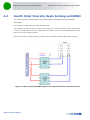
A.2 Fourth Order Diversity, Beam Forming and MIMO..............................................690
A.3 Fourth Order Diversity, MIMO...........................................................................691
A.3.1
Wide Double Dual Slant Array ......................................................................... 691
A.3.2
Narrow Dual Dual Slant Array .......................................................................... 692
A.4 Second Order Diversity.....................................................................................693
A.4.1
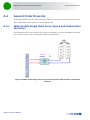
Wide Double Single Slant Array (Space and Polarization Diversity)................. 693
A.4.2
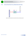
Narrow Dual Slant Array (Polarization Diversity)............................................. 694
A.4.3
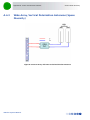
Wide Array, Vertical Polarization Antennas (Space Diversity) ......................... 695
Glossary............................................................................................................ 696
4Motion System Manual
xxvii
Chapter 1 - System
Description
In This Chapter:
“About WiMAX” on page 2
“4Motion Solution” on page 3
“The Base Transceiver Station” on page 11
“Element Management Systems” on page 21
“Specifications” on page 22
Chapter 1 - System Description
1.1
About WiMAX
About WiMAX
Emanating from the broadband world and using all-IP architecture, mobile WiMAX is the leading
technology for implementing personal broadband services. With huge market potential and affordable
deployment costs, mobile WiMAX is on the verge of a major breakthrough. No other technology offers
a full set of chargeable and differentiated voice, data, and premium video services in a variety of wireless
fashions - fixed, portable and mobile - that increase revenue and reduce subscriber churn.
WiMAX technology is the solution for many types of high-bandwidth applications at the same time
across long distances and will enable service carriers to converge the all-IP-based network for triple-play
services data, voice, and video.
WiMAX with its QoS support, longer reach, and high data capacity is positioned for fixed broadband
access applications in rural areas, particularly when distance is too large for DSL and cable, as well as in
urban/suburban areas of developing countries. Among applications for residential are high speed
Internet, Voice Over IP telephony and streaming video/online gaming with additional applications for
enterprise such as Video conferencing, Video surveillance and secured Virtual Private Network (with
need for high security). WiMAX technology allows covering applications with media content requesting
more bandwidth.
WiMAX allows portable and mobile access applications, with incorporation in notebook computers and
PDAs, allowing for urban areas and cities to become “metro zones” for portable and mobile outdoor
broadband wireless access. As such WiMAX is the natural complement to 3G networks by offering
higher bandwidth and to Wi-Fi networks by offering broadband connectivity in larger areas.
The WiMAX Forum is an organization of leading operators and communications component and
equipment companies. The WiMAX Forum’s charter is to promote and certify the compatibility and
interoperability of broadband wireless access equipment that conforms to the Institute for Electrical and
Electronics Engineers (IEEE) 802.16 and ETSI HiperMAN standards. The ultimate goal of the WiMAX
Forum is to accelerate the introduction of cost-effective broadband wireless access services into the
marketplace. Standards-based, interoperable solutions enable economies of scale that, in turn, drive
price and performance levels unachievable by proprietary approaches, making WiMAX Forum Certified
products.
4Motion System Manual
2
Chapter 1 - System Description
1.2
4Motion Solution
1.2.1
4Motion Solution Highlights
4Motion Solution
Leveraging its extensive experience in Broadband Wireless Access (BWA) systems, leading technology
and current favorable economics for broadband and mobile services, Alvarion's 4Motion mobile WiMAX
solution represents the next evolution in communications.
With 4Motion, Alvarion offers a diversified range of products and services for all operators. Integrating
the most advanced and adaptive radio management and control technologies, 4Motion optimizes usage
of the operator's spectrum and network resources. At the same time, the solution supports the most
stringent quality of service (QoS) requirements for next-generation applications such as video and
gaming.
As a mobile solution, 4Motion network can be efficiently integrated with existing networks, including
3G, DSL, satellite, and cable, to provide multiple service applications.
4Motion enables operators and their customers to address the following consumer and enterprise
market segments:
“Best effort" fixed broadband access (DSL equivalent)
Portable broadband access
"Personal broadband" (handheld) access
Mobile broadband (including full handover and roaming support)
4Motion supports the following services:
IP-based and Ethernet-based services (e.g. VoIP, video streaming, gaming)
QoS and application-based prioritization and de-prioritization
4Motion is designed as an end-to-end solution based on the following elements:
BTS (Base Transceiver Station) equipment with an optional localized access service network gateway
(ASN-GW):
»
Indoor modular Macro BTS.
»
All-outdoor modular Macro BTS.
»
The all-outdoor single sector Micro BTS
Optional centralized, fully integrated ASN-GW, which may be offered as a part of an end-to-end
solution that includes third-party partners' equipment
AAA servers provided by either Alvarion or its leading WiMAX partners
AlvariSTAR Element management system supporting NMS and OSS systems
Customer premises equipment and handsets
4Motion System Manual
3
Chapter 1 - System Description
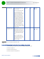
4Motion Solution
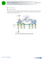
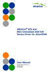
Figure 1-1 illustrates the entire service provider environment and 4Motion solution elements within the
radio access network, core network and subscriber environment.
Figure 1-1: 4Motion Solution Elements
Alvarion believes that compliance with standard-driven open architecture protects the infrastructure
investment, and opens the system to a variety of fully interoperable end-user devices. As such, 4Motion
is designed with open architecture and interfaces according to the WiMAX Forum networking working
group (NWG) profile C, which supports openness and enables flat as well as hierarchical topologies. In
addition, by keeping the radio resource management functionality in the Base Transceiver Station only,
Profile C delivers a faster, optimized handover mechanism.
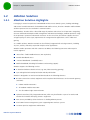
1.2.2
WiMAX Network Reference Model
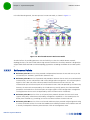
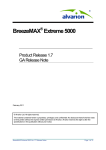
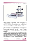
Figure 1-2 and Figure 1-3 show the basic mobile WiMAX network architecture, with a single ASN-GW
and with multiple ASN-GWs, as defined by the WiMAX Forum NWG
4Motion System Manual
4
Chapter 1 - System Description
4Motion Solution
.
Figure 1-2: Mobile WiMAX Network Reference Model
Figure 1-3: ASN Reference Model containing Multiple ASN-GWs
The various components and entities involved in the networking architecture are:
1.2.2.1
Access Service Network (ASN)
An ASN is defined as a complete set of network functions needed to provide radio access to a WiMAX
subscriber. The ASN provides the following mandatory functions:
4Motion System Manual
5
Chapter 1 - System Description
4Motion Solution
WiMAX Layer-2 (L2) connectivity with WiMAX mobile station (MS)
Transfer of AAA messages to the WiMAX subscriber's home network service provider (H-NSP) for
authentication, authorization and session accounting for subscriber sessions
Network discovery and selection of the WiMAX subscriber's preferred NSP
Relay functionality for establishing Layer-3 (L3) connectivity with a WiMAX MS (i.e. IP address
allocation)
Radio resource management
ASN-CSN tunneling
ASN anchored mobility
An ASN is comprised of network elements such as one or more base transceiver stations and one or
more ASN gateways. An ASN may be shared by more than one connectivity service network (CSN).
1.2.2.2
Connectivity Service Network (CSN)
A CSN is defined as a set of network functions that provide IP connectivity services to WiMAX
subscribers. A CSN may offer the following functions:
MS IP address and endpoint parameter allocation for user sessions
Internet access
AAA proxy or server
Policy and admission control based on user subscription profiles
ASN-CSN tunneling support
WiMAX subscriber billing and inter-operator settlement
WiMAX services such as location-based services, connectivity for peer-to-peer services, provisioning,
authorization and/or connectivity to IP multimedia services, and facilities to support lawful intercept
services such as those compliant with Communications Assistance Law Enforcement Act (CALEA)
procedures
A CSN is comprised of network elements such as routers, proxy/servers, user databases, and
inter-working gateway devices.
1.2.2.3
Network Access Provider (NAP)
An NAP is a business entity that provides WiMAX radio access infrastructure to one or more WiMAX
network service providers (NSPs). A NAP implements this infrastructure using one or more ASNs.
1.2.2.4
Network Service Provider (NSP)
An NSP is a business entity that provides IP connectivity and WiMAX services to WiMAX subscribers
compliant with the established service level agreement. The NSP concept is an extension of the Internet
service provider (ISP) concept, providing network services beyond Internet access. To provide these
4Motion System Manual
6
Chapter 1 - System Description
4Motion Solution
services, an NSP establishes contractual agreements with one or more NAPs. An NSP may also establish
roaming agreements with other NSPs and contractual agreements with third-party application providers
(e.g. ASP, ISP) for the delivery of WiMAX services to subscribers. From a WiMAX subscriber standpoint,
an NSP may be classified as a home or visited NSP.
1.2.2.5
Base Station (BS)
The WiMAX BS is an entity that implements the WiMAX MAC and PHY in compliance with the IEEE
802.16e standard. A BS operates on one frequency assignment, and incorporates scheduler functions
for uplink and downlink resources.
The basic functionality of the BS includes:
IEEE 802.16e OFDMA PHY/MAC entity
R6 and R8 functionality according to NWG definitions
Extensible Authentication Protocol (EAP) relay
Control message authentication
User traffic authentication and encryption
Handover management
QoS service flow management entity
1.2.2.6
ASN Gateway (ASN-GW)
The ASN-GW is a network entity that acts as a gateway between the ASN and CSN. The ASN functions
hosted in an ASN-GW may be viewed as consisting of two groups - the decision point (DP) and
enforcement point (EP). The EP includes bearer plane functions, and the DP includes non-bearer plane
functions.
The basic DP functionality of the ASN-GW includes:
Implementation of EAP Authenticator and AAA client
Termination of RADIUS protocol against the selected CSN AAA server (home or visited AAA server) for
MS authentication and per-MS policy profile retrieval
Storage of the MS policy profile
Generation of authentication key material
QoS service flow authorization entity
AAA accounting client
The basic EP functionality of the ASN-GW includes:
Classification of downlink data into generic routing encapsulation (GRE) tunnels
Packet header suppression functionality
4Motion System Manual
7
Chapter 1 - System Description
4Motion Solution
DHCP functionality
Handover functionality
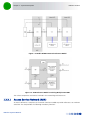
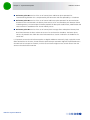
The WIMAX Forum NWG has adopted two different approaches for ASN architecture - centralized and
distributed: In the centralized approach there is at least one central ASN-GW, and the NPU operates in
transparent mode, as shown in Figure 1-4.
Figure 1-4: Centralized Network Reference Model
4Motion System Manual
8
Chapter 1 - System Description
4Motion Solution
In the distributed approach, the NPU operates in ASN-GW mode, as shown in Figure 1-5.
Figure 1-5: Distributed Network Reference Model
Alvarion believes in providing operators with the flexibility to select the mobile WiMAX network
topology that best suits their needs and existing network architecture. Therefore, 4Motion is designed to
support both distributed and centralized topology approaches according to WiMAX Forum NWG profile
C.
1.2.2.7
Reference Points
Reference point R1 consists of the protocols and procedures between the MS and ASN as per the
air-interface (PHY and MAC) specifications (IEEE 802.16e).
Reference point R2 consists of protocols and procedures between the MS and CSN associated with
authentication, services authorization and IP host configuration management. This reference point is
logical in that it does not reflect a direct protocol interface between the MS and CSN. The
authentication part of reference point R2 runs between the MS and CSN operated by the home NSP,
however, the ASN and CSN operated by the visited NSP may partially process the aforementioned
procedures and mechanisms. Reference point R2 might support IP host configuration management
running between the MS and CSN (operated by either the home NSP or visited NSP).
Reference point R3 consists of the set of control plane protocols between the ASN and CSN to
support AAA, policy enforcement and mobility management capabilities. It also encompasses the
bearer plane methods (e.g. tunneling) to transfer user data between the ASN and CSN.
Reference point R4 consists of the set of control and bearer plane protocols originating/terminating
in various functional entities of an ASN that coordinate MS mobility between ASNs and ASN-GWs. R4
is the only interoperable reference point between similar or heterogeneous ASNs.
4Motion System Manual
9
Chapter 1 - System Description
4Motion Solution
Reference point R5 consists of the set of control plane and bearer plane protocols for
internetworking between the CSN operated by the home NSP and that operated by a visited NSP.
Reference point R6 consists of the set of control and bearer plane protocols for communication
between the BS and ASN-GW. The bearer plane consists of an intra-ASN data path between the BS
and ASN gateway. The control plane includes protocols for data path establishment, modification and
release control in accordance with the MS mobility events.
Reference point R8 consists of the set of control plane message flows and optional bearer plane
data flows between the base stations to ensure a fast and seamless handover. The bearer plane
consists of protocols that allow data transfer between base stations involved in the handover of a
certain MS.
It is important to note that all reference points are logical and do not necessarily imply a physical or even
direct connection. For instance, the R4 reference point between ASN-GWs might be implemented across
the NAP internal transport IP network, in which case R4 traffic might traverse several routers from the
source to the destination ASN-GW.
4Motion System Manual
10
Chapter 1 - System Description
1.3
The Base Transceiver Station
The Base Transceiver Station
The 4Motion solution features a multi-carrier, high-power Base Transceiver Station (BTS). Designed for
high availability and redundancy, it utilizes a central networking and management architecture, and a
range of diversity schemes.
The BTS main features include:
R1 support - 802.16e interface handling (e.g. PHY, MAC, CS, Scheduler, ARQ) and processes such as
handover, power control and network entry
R6 support - communication with ASN-GW
EAP proxy in ASN-GW mode
Handover triggering for mobility tunnel establishment - R6 (GRE tunnel)
Local QoS PEP for traffic via air interface (or SFM) and admission control
Hand-Over (HO) control function
Radio resource management agent
Key generation (TEK, KEK) and traffic encryption
The 4Motion Base Transceiver Station equipment includes:
The indoor modular Macro BTS.
The all-outdoor modular Macro BTS.
The all-outdoor single sector Micro BTS.
Outdoor Radio Units.
GPS Receiver
Power-Feeder (optional for the indoor Macro BTS).
1.3.1
The Indoor Macro BTS
1.3.1.1
The BreezeMAX Shelf
The BreezeMAX shelf is an indoor -48 VDC powered 8U cPCI PICMG 2.x standard shelf prepared for
installation in a 19" or 21" (ETSI) rack. This chassis has a total of nine double-Euro (6U high) slots and six
4Motion System Manual
11
Chapter 1 - System Description
The Base Transceiver Station
single-Euro (3U high) slots. All the modules are hot swappable, and high availability can be provided
through multiple redundancy schemes.
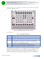
Figure 1-6: BreezeMAX Shelf (with all modules installed)
The shelf modules are:
Table 1-1: BreezeMAX Shelf Modules
Module
Description
PIU
3U high power interface unit, 1+1 redundancy, -48VDC, protection, filters
PSU
3U high power supply unit, up to 3+1 redundancy
NPU
6U high network processing unit with optional ASN-GW functionality, hardware ready
for 1+1 redundancy (NPU redundancy is not supported in the current release),
1000/100 Base-T main network interface, 1000/100 Base-T cascade interface and
100/10 Base-T out-of-band management interface
AU
6U high access unit, 4-channel, 802.16e MAC-modem-baseband IF card
AVU
2U high air ventilation unit, 9+1 redundancy fans with alarm control
The six single-Euro slots are intended for one or two redundant Power Interface Units (PIUs) and up to
four redundant Power Supply Units (PSUs). One of the double Euro slots (Slot 5) is dedicated to the NPU
module, with interfaces for network backhaul, in-band and out-of-band (OOB) management
connections. Another double-Euro slot (Slot 6) is reserved for an optional redundant NPU (the shelf is
HW-ready for NPU redundancy). The remaining seven double-Euro slots (1-4, 7-9) are dedicated for
4Motion System Manual
12
Chapter 1 - System Description
The Base Transceiver Station
Access Unit (AU) modules, thereby enabling various network topologies with up to 6 simultaneously
operational AUs, and future redundancy configurations. In addition, the shelf contains an Air Ventilation
Unit (AVU).
1.3.1.2
NPU
The Network Processing Unit is the controller of the Base Transceiver Station. Serving as the central
processing unit that manages the BTS components, the NPU aggregates traffic to/from the AU modules,
and transfers it to/from the IP backbone through a dedicated Gigabit/Fast Ethernet interface. In addition,
the NPU can be operated in ASN-GW mode, in which case it also implements ASN-GW functionality.
When operating in ASN-GW mode, the NPU implements the R3 reference point toward the CSN, R4
reference point toward other ASN-GWs, and R6 reference point toward AU/BSs. The R8 reference point
traffic is transparently relayed between AU/BSs (intra- or inter-BTS).
When operating in transparent mode, the NPU transparently relays R6 and R8 reference-point traffic
between AU/BSs (intra- or inter-BTS).
The BreezeMAX shelf is hardware-ready for 1+1 NPU card redundancy.
The NPU main functions, when operating in transparent mode, are:
Aggregate backbone Ethernet connectivity for user and control traffic
Aggregate backbone Ethernet connectivity for management traffic (in-band or out-of-band)
Connection to a cascaded shelf (future feature)
L2 switch forwarding capabilities
Internal and external traffic VLAN encapsulation
QoS marking
Overall operation, control and shelf management, including AU diagnostics and control, PSU
monitoring, AVU management and redundancy support
Local and remote extensive management support via CLI (Telnet, SSH) and SNMP, including software
download, fault and performance management
Alarm management, including external alarm inputs and activation of external devices
Synchronization, including GPS receiver interface, clock and IF reference generation and distribution
to the shelf modules, and holdover handling
Security functionalities such as rate limiting and access control lists
When operating in ASN-GW mode, the following additional ASN-GW functions are supported:
EAP authenticator
RADIUS AAA client
AAA accounting client
4Motion System Manual
13
Chapter 1 - System Description
The Base Transceiver Station
MS policy profile storage
QoS service flow authorization
Classification of downlink data into service flows
Packet header suppression functionality
Multiple service provider support (multihost) for improved security and wholesale model
DHCP functionality - internal server, DHCP proxy, DHCP relay (with Option 82 support)
Handover functionality
GRE encapsulation/decapsulation
IP-in-IP encapsulation/decapsulation
Transparent VLAN (single tag) and QinQ (dual tag) encapsulation
Fragmentation/reassembly
R4/R6/R3 interfaces implementation
Keep-alive signaling towards the relevant BSs and other ASN-GWs for enhanced management of
service availability
When several shelves are collocated, the NPU cascade interface can be used for shelf interconnection. In
this architecture, the NPU that is directly connected to the backhaul implements a layer-2 connection
toward the NPUs in the cascaded shelves. Bearer, control and management traffic is sent over the
cascade connection. Synchronization and GPS backup power are sent toward the NPUs in the cascaded
shelves through the GPS/SYNC ports.
GPS synchronization cascading will be implemented in a future release.
1.3.1.3
AU
The Access Unit module performs the WiMAX/IEEE 802.16e BS function according to the NWG Profile C
definitions via digital signal processors (DSPs) and field-programmable gate array (FPGA) technology. The
AU module is designed to support high-traffic throughput and enable diversity, MIMO and AAS, thereby
extending capacity and range.
The AU implements the following functionality:
802.16e multi-channel OFDMA PHY
Up to four-channel support (Tx/Rx)
Diversity and future AAS
Flexible channel bandwidth - up to 20 MHz
Flexible FFT size - up to 2048 points
Wide variety of reuse patterns
Advanced channel coding (CTC)
4Motion System Manual
14
Chapter 1 - System Description
The Base Transceiver Station
HARQ
Rate adaptation
High-performance CDMA detector
IF interface to RF ODU
MAC-PHY interface
Link management (network entry, basic capabilities negotiation, authentication and registration,
connection management)
Fragmentation/ reassembly
QoS PEP for air interface traffic
QoS DSCP marking
Scheduling - connections quota computation for all data delivery types
Frame/burst building
Power save
Handover management
Power control
R1/R6/R8 functionality
Data path mapping between R6 (GRE) and 802.16e interfaces
Traffic authentication and encryption
Authentication relay
Security key receiver
Context client/server
ID to IP address resolution for ASN entities
IP and Ethernet convergence sublayers
Keep-alive signaling towards the relevant ASN-GWs for enhanced management of service availability
The AU design is based on Alvarion's programmable, off-the-shelf, cutting-edge components, in order
to provide a future-proof solution with excellent cost and performance.
The AU card interfaces with the NPU card for R6/R8 functionality, as well as control, synchronization and
management between the NPU and AU.
The AU implements four receive and transmit channels, each of them is HW-ready for up to 20 MHz
bandwidth.
4Motion System Manual
15
Chapter 1 - System Description
1.3.1.4
The Base Transceiver Station
PIU
The single-Euro Power Interface Unit module serves as the interface between the DC power source and
both the PSU modules and external ODU radio transceivers.
The PIU filters and stabilizes the input power, and protects the system from power problems such as
over-voltage, surge pulses, reverse polarity connection, and short circuits. It filters high-frequency
interference (radiated emissions) and low-frequency interference (conducted emissions) at the external
power source. Each shelf contains two slots for optional 1+1 PIU redundancy. One PIU is sufficient to
support a fully populated shelf, and two modules provide redundant power feeding (i.e. from two input
sources), while avoiding current flow between the two input sources.
1.3.1.5
PSU
The single-Euro Power Supply Unit module is a -48 VDC power supply unit that generates low-voltage
DC output to comply with PICMG 2.x standard requirements. Each shelf can contain up to four PSU
modules supporting N+1 redundancy configuration scheme.
Table 1-2 displays the number of PSU modules (excluding redundant units) required for various Base
Station configurations without NPU redundancy (one NPU):
Table 1-2: PSU Requirements, Configurations with one NPU (excluding PSU redundancy)
1.3.1.6
Number of AUs
Minimum Required Number of PSUs
1-4
2
5-6
3
AVU
The 2U-high AVU includes a 1U-high integral chamber for inlet airflow and a 1U-high fan tray with an
internal alarm module. To support high availability, the fan tray includes 10 brushless fans (9 fans are
sufficient for cooling a fully-loaded shelf). Fan failure is indicated by both the front panel LEDs and a trap
sent to the management system. To further support high availability, the chassis may operate without
the hot-swappable fan tray for up to 10 minutes until the AVU is replaced.
1.3.2
The Macro Outdoor BTS
The Macro Outdoor BTS is a modular scalable and reliable all-outdoor platform enabling extended and
flexible installation capabilities while sustaining all the features and capabilities of the 4Motion solution.
The All-Outdoor Macro BTS portfolio includes the following system elements:
NAU (Network Access Unit): A full-size enclosure containing NPU and AU cards.
DAU (Dual Access Unit): A full-size enclosure containing two AU cards.
SAU (Single Access Unit): A half-size enclosure containing one AU card.
4Motion System Manual
16
Chapter 1 - System Description
The Base Transceiver Station
The full-size enclosure is similar to the enclosure of the 4x2 ODUs (see Section 1.3.4), supporting flexible
mounting options for system components, including back-to-back and side-by-side mounting. The units
are available with either full (4-channels) AUs or with 2-channels AUs.
The modular architecture and different unit types enable building a variety of configurations using up to
six AUs with either 2 or 4 channels, addressing a pay-as-you-grow deployment. The functionality is the
same as described for the NPU (see Section 1.3.1.2) and AU (see Section 1.3.1.3) cards of the Indoor
Macro BTS, with a few minor exceptions.
1.3.3
The Outdoor Micro BTS
Micro Outdoor BTS is a full-outdoor small form factor WiMAX Base Transceiver Station. The Micro
Outdoor BTS complements Macro BTS deployments providing white spots coverage, cell extension and
capacity boost. It provides excellent cost/performance in addressing low dense population areas (rural &
suburban). It also provides an effective solution for installation constrained areas through light-pole,
roof-top or wall mount options.
The Micro BTS comprises a single BS and two integrated radios connected to an external dual-slant
antenna. The functionality of the Micro BTS is very similar to that of a two-channel NAU unit (an NPU
with a single two-channel AU) operating with an external ASN-GW (Centralized architecture).
Micro BTS systems are currently available in the 2.5 GHz and 3.5 GHz bands.
1.3.4
ODUs for Macro (Indoor/Outdoor) BTS
The outdoor unit (ODU) is a high-power, multi-carrier radio unit that connects to one or more external
antennas. It is designed to provide high system gain and interference robustness utilizing high transmit
power and low noise figure. It is HW-ready for supporting a bandwidth of up to 20 MHz for the 4x2
ODUs and 30 MHz for the 2x2 ODUs, enabling future options such as increased capacity through the
use of a multiplexer or wider frequency channels.
The following ODU port configurations will be available:
1x1(1Rx by 1 Tx): One receive port, one transmit port (one Tx/Rx interface)
2x2 (2Rx by 2Tx): Two receive ports, two transmit ports (two Tx/Rx interfaces)
4x2 (4Rx by 2Tx): Four receive ports, two transmit ports (two Tx/Rx interfaces, two Rx only interfaces)
The wide range of ODU types will enable efficient utilization of various second and fourth order transmit
and receive diversity schemes. Some of the 4x2 and all 2x2 ODUs support Beam Forming capabilities for
enhanced performance.
The following table provides details on the currently available ODUs following the WiMAX Forum’s
definitions:
4Motion System Manual
17
Chapter 1 - System Description
The Base Transceiver Station
Table 1-3: ODU Types
Band
(GHz)
ODU Frequency
Range (MHz)
ODU Port
Configuration
ODU
Bandwidth
(MHz)
ODU Max
Tx Power
(dBm)
BF
Support
2.3
2300-2360
1Rx by 1Tx
Up to 10
36
No
2340-2400
1Rx by 1Tx
Up to 10
36
No
2305 - 2317, 2348 2360 (includes WCS
filter)
1Rx by 1Tx
Up to 10
36
No
2300-2400
2Rx by 2Tx
Up to 30
38
Yes
2496-2602 (band A)
1Rx by 1Tx
Up to 10
36
No
2590-2690 (band B)
1Rx by 1Tx
Up to 10
36
No
2485-2690
2Rx by 2TX
Up to 30
38
Yes
2496-2602 (band A)
4Rx by 2Tx
Up to 20
38
No
2590-2690 (band B)
4Rx by 2Tx
Up to 20
38
No
2485-2690
4Rx by 2Tx
Up to 20
38
Yes
2560-2570
4Rx by 2Tx
Up to 10
37
No
3300-3355
1Rx by 1 Tx
Up to 14
32
No
3345-3400
1Rx by 1Tx
Up to 14
33
No
3400-3455
1Rx by 1Tx
Up to 14
34
No
3445-3500
1Rx by 1Tx
Up to 14
34
No
3500-3555
1Rx by 1Tx
Up to 14
34
No
3545-3600
1Rx by 1Tx
Up to 14
34
No
3400-3600
2Rx by 2Tx
Up to 30
37
Yes
3400-3600
4Rx by 2Tx
Up to 20
37
No
3400-3600
4Rx by 2Tx
Up to 20
37
Yes
3475-3675
2Rx by 2Tx
Up to 30
37
Yes
3650-3700
1Rx by 1Tx
Up to 14
22
No
3600-3800
4Rx by 2Tx
Up to 20
36
Yes
2.5
3.3
3.5
3.6
1.3.5
Power Feeder
The PIU of the indoor Macro BTS can support a maximum current of 58 A (@-40.5 VDC). In certain
installations with a relatively high number of ODUs this current may not be sufficient to power the shelf
and all the ODUs. In such installations the ODU Power Feeder is used as an additional power source
4Motion System Manual
18
Chapter 1 - System Description
The Base Transceiver Station
providing power (-48 VDC) to ODUs. It transfers transparently all signals between the AU and the ODU,
while injecting DC power received from an external source. Each ODU Power Feeder unit can serve up to
four ODUs. Up to three ODU Power Feeder units can be installed in a 1U high Power Feeder panel.
1.3.6
Antenna
In the 4Motion architecture, the antenna is approached as an independent element. This provides the
operator with the flexibility to select the antennas source according to its supplier policy. To ensure the
availability of antennas that complement the 4Motion solution, Alvarion works closely with several
antenna suppliers to ensure availability of antennas that comply with its requirements.
In cases where the operator prefers other antenna vendors, Alvarion can provide a recommended
antenna specification based on the required antennas types.
Antennas may support one or several different downtilt options:
Mechanical Down-Tilt (MDT) using a suitable mounting kit.
Electrical Down-Tilt (EDT) that may be either fixed or adjustable using a special adjustment screw.
Remote Electrical Tilt (RET) through a special interface.
Alvarion offers also AISG (Antenna Interface Standards Group) compliant electrical downtilt control kit
enabling remote tilt control for antennas that support RET.
For details on antennas offered by Alvarion refer to “Antennas” on page 41. For more information on
recommended antenna configurations and required antennas refer to Appendix A.
1.3.7
GPS
GPS is used to synchronize the air link frames of Intra-site and Inter-site located Base Transceiver Stations
to ensure that in all Base Stations the air frame will start at the same time, and that all Base Stations will
switch from transmit (downlink) to receive (uplink) at the same time. This synchronization is necessary to
prevent Intra-site and Inter-site interference and Base stations saturation (assuming that all Base Stations
are operating with the same frame size and with the same DL/UL ratio).
In order for the system to be synchronized, the GPS have to first acquire at least 4 satellites. After that
the GPS reception can be reduced to 1 satellite. If no satellite is received the BTS will go to holdover state
where internal clock is provided to synchronize the BTS.
1.3.7.1
Outdoor GPS Receiver for the Macro BTS
The all-outdoor GPS Receiver is a pole mountable GPS receiver and antenna in a single environmentally
protected enclosure. The receiver is powered from the NPU, and it can be installed at a distance of up to
100m from the NPU. In the BMAX-Timing GPS-OGR model, a special adaptor cable is required between
the GPS cable and the NPU. When available, no adaptor cable will be required for the BMAX-4M-GPS.
4Motion System Manual
19
Chapter 1 - System Description
1.3.7.2
The Base Transceiver Station
GPS Antenna Kit for the Micro BTS
The Micro BTS includes an internal GPS receiver with hold over mechanism in case GPS is lost or satellites
synchronization was not reached.
Alvarion offers the miniature GPS antenna that can be installed at a distance of up to 3m from the BTS.
4Motion System Manual
20
Chapter 1 - System Description
1.4
Element Management Systems
Element Management Systems
The end-to-end IP-based architecture of the system enables full management of all components, using
standard management tools. An SNMP agent in the NPU implements proprietary MIBs for remote setting
of operational modes and parameters of the Base Transceiver Station equipment. Security features
incorporated in the equipment restrict the access for management purposes.
Alvarion offers the following management tool:
1.4.1
AlvariSTAR
AlvariSTAR is a comprehensive carrier-class Element Management System (EMS) for Alvarion’s Broadband
Wireless Access systems. AlvariSTAR is designed for today's most advanced Network Operation Centers
(NOCs), providing the network Operation, Administration and Maintenance (OA&M) staff and managers
with all the network surveillance, monitoring and configuration and service provisioning capabilities
required to effectively manage the network while keeping the resources and expenses at a minimum.
AlvariSTAR offers the network's OA&M staff with a unified, scalable and distributable management
system. Utilizing distributed client-server architecture, the user is provided with a robust, scalable and
fully redundant management system in which all single points of failure can be avoided.
AlvariSTAR provides the following management functionality:
Device Discovery
Device Inventory
Topology
Fault Management
Configuration Management
Service Management
Data Collection
Performance Monitoring
Device embedded software upgrade
BTS duplication and template-based configuration modification of multiple BTS simultaneously.
Security Management
Event Forwarding to other Network Management Systems.
4Motion System Manual
21
Chapter 1 - System Description
1.5
Specifications
1.5.1
Modem & Radio
Specifications
Table 1-4: General Modem & Radio Specifications
Item
Description
Operation Mode
TDD
Channel Bandwidth
5 MHz
7 MHz (not applicable for the 2.x GHz band)
10 MHz
1.5.2
Central Frequency Resolution
0.125 MHz (actual configurable frequencies depend on the local
radio regulations and allocated spectrum)
Modulation
OFDM modulation, 1024/512 FFT points;
QPSK, QAM16, QAM64
Access Method
OFDMA
FEC
Convolutional Turbo Coding: 1/2, 2/3, 3/4, 5/6
Sensitivity (per channel)*
Table 1-5: Per Channel Sensitivity, AWGN @ PER=1%
Modulation
& Coding
Sensitivity (dBm),
5 MHz Bandwidth
Sensitivity (dBm),
7 MHz Bandwidth
Sensitivity (dBm),
10 MHz Bandwidth
QPSK 1/2
-97.3
-95.8
-94.2
QPSK 3/4
-94.9
-93.4
-91.8
16QAM 1/2
-92.2
-90.7
-89.1
16QAM 3/4
-88.3
-86.8
-85.2
64QAM1/2
-86.8
-85.3
-83.7
64QAM2/3
-83.0
-81.5
-79.9
64QAM3/4
-82.2
-80.7
-79.1
64QAM5/6
-81.0
-79.5
-77.9
* For second order receive diversity configurations sensitivity is improved by 3 dB.
For fourth order receive diversity configurations sensitivity is improved by 6 dB.
4Motion System Manual
22
Chapter 1 - System Description
Specifications
1.5.3
ODUs
1.5.3.1
2.3 GHz Band
1.5.3.1.1
2.3 GHz Band 1x1 ODUs
Table 1-6: 2.3 GHz Band 1x1 ODUs Specifications
Item
Description
Frequency Band
ODU-HP-2.3: 2300-2360 MHz
ODU-HP-2.3-WCS: 2305 - 2317, 2348 - 2360 MHz
(includes WCS filter)
ODU-HP-2.3b: 2340-2400 MHz
Ports Configuration
1x1 (1Rx, 1Tx)
Bandwidth Support
Up to 10 MHz, 5 & 10 MHz SAW filters
Maximum Tx Power)
36 dBm
Tx Power Control Range
10 dB, in 1 dB steps
Tx Power Accuracy
+/- 1 dB
Maximum Input Power @ antenna port
-60 dBm before saturation, -8 dBm before damage
Noise Figure
4.6 dB typical, 6.0 dB maximum
Dimension
ODU-HP-2.3-WCS: 329 x 157 x 209 mm
Other ODUs: 329 x 157 x 169 mm
Weight
ODU-HP-2.3-WCS: 8.6 Kg
Other ODUs: 6.1 Kg
Connectors
ANT: N-Type jack, 50 Ohm, lightning protected
IF: TNC jack, 50 Ohm, lightning protected
Power Source
-40.5 to -60 VDC over the IF cable
Power Consumption
Transmit - 90W maximum
Receive - 20W maximum
1.5.3.1.2
2.3 GHz Band 2x2 ODU
Table 1-7: 2.3 GHz Band 2x2 ODU Specifications
Item
Description
Frequency Band
ODU-2300-2400-000N-38-2X2-N-0: 2300-2400 MHz*
Ports Configuration
2x2 (2Rx, 2Tx)
4Motion System Manual
23
Chapter 1 - System Description
Specifications
Table 1-7: 2.3 GHz Band 2x2 ODU Specifications
Item
Description
Bandwidth Support
Up to 30 MHz
Beam Forming Support
Yes
Maximum Tx Power)
38 dBm*
Tx Power Control Range
10 dB, in 1 dB steps
Tx Power Accuracy
+/- 1 dB
Maximum Input Power @
antenna port
-60 dBm before saturation, -8 dBm before damage
Noise Figure
4.5 dB typical, 5.5 dB maximum
Dimension
420 x 340 x 270 mm
Weight
17 Kg
Connectors
ANT: 2 x N-Type jack, 50 Ohm, lightning protected
IF: 2 x TNC jack, 50 Ohm, lightning protected
Power Source
-40.5 to -60 VDC over the IF cable
Power Consumption
Transmit - 180W maximum
Receive - 40W maximum
* With the optional external WCS filter, the frequency range is 2305-2315, 2350-2360 MHz, and Tx
power is reduced by 1 dB.
1.5.3.2
2.5 GHz Band
1.5.3.2.1
2.5 GHz Band 1x1 ODUs
Table 1-8: 2.5 GHz Band 1x1 ODUs Specifications
Item
Description
Frequency Band
ODU-HP-2.5A: 2496-2602 MHz (Band A)
ODU-HP-2.5B: 2590-2690 MHz (Band B)
Ports Configuration
1x1 (1Rx, 1Tx)
Bandwidth Support
Up to 10 MHz
Maximum Tx Power)
36 dBm
Tx Power Control Range
10 dB, in 1 dB steps
Tx Power Accuracy
+/- 1 dB
Maximum Input Power @
antenna port
-60 dBm before saturation, -8 dBm before damage
4Motion System Manual
24
Chapter 1 - System Description
Specifications
Table 1-8: 2.5 GHz Band 1x1 ODUs Specifications
Item
Description
Noise Figure
4.6 dB typical, 6.0 dB maximum
Dimension
329 x 157 x 209 mm
Weight
6.1 Kg
Connectors
ANT: N-Type jack, 50 Ohm, lightning protected
IF: TNC jack, 50 Ohm, lightning protected
Power Source
-40.5 to -60 VDC over the IF cable
Power Consumption
Transmit - 90W maximum
Receive - 20W maximum
4Motion System Manual
25
Chapter 1 - System Description
1.5.3.2.2
Specifications
2.5 GHz Band 2x2 ODUs
Table 1-9: 2.5 GHz Band 2x2 ODUs Specifications
Item
Description
Frequency Band
ODU-2485-2690-000N-38-2X2-N-0: 2485-2690 MHz
Ports Configuration
2x2 (2Rx, 2Tx)
Bandwidth Support
Up to 30 MHz
Beam Forming Support
Yes
Maximum Tx Power)
38 dBm
Tx Power Control Range
10 dB, in 1 dB steps
Tx Power Accuracy
+/- 1 dB
Maximum Input Power @
antenna port
-60 dBm before saturation, -8 dBm before damage
Noise Figure
4.5 dB typical, 5.5 dB maximum
Dimension
420 x 340 x 270 mm
Weight
17 Kg
Connectors
ANT: 2 x N-Type jack, 50 Ohm, lightning protected
IF: 2 x TNC jack, 50 Ohm, lightning protected
Power Source
-40.5 to -60 VDC over the IF cable
Power Consumption
Transmit - 180W maximum
Receive - 40W maximum
1.5.3.2.3
2.5 GHz Band 4x2 ODUs
Table 1-10: 2.5 GHz Band 4x2 ODUs Specifications
Item
Description
Frequency Band
ODU-2496-2602-000N-38-4x2-N-0: 2496-2602 MHz (Band A)
ODU-2590-2690-000N-38-4x2-N-0: 2590-2690 MHz (Band B)
ODU-2485-2690-000N-38-4X2-N-0: 2485-2690 MHz
ODU-2560-2570-000N-37-4X2-N-0: 2560-2570 MHz
Ports Configuration
4x2 (4Rx, 2Tx)
Bandwidth Support
Up to 20 MHz
Beam Forming Support
ODU-2485-2690-000N-38-4X2-N-0
4Motion System Manual
26
Chapter 1 - System Description
Specifications
Table 1-10: 2.5 GHz Band 4x2 ODUs Specifications
Item
Description
Maximum Tx Power)
38 dBm
For ODU-2560-2570-000N-37-4X2-N-0: 37 dBm.
Tx Power Control Range
10 dB, in 1 dB steps
Tx Power Accuracy
+/- 1 dB
Maximum Input Power @
antenna port
-60 dBm before saturation, -8 dBm before damage
Noise Figure
4.5 dB typical, 5.5 dB maximum
Dimension
420 x 340 x 270 mm
Weight
17 Kg
Connectors
ANT: 4 x N-Type jack, 50 Ohm, lightning protected
IF: 4 x TNC jack, 50 Ohm, lightning protected
Power Source
-40.5 to -60 VDC over the IF cable
Power Consumption
Transmit - 180W maximum
Receive - 50W maximum
1.5.3.2.4
Compliance with ETSI Regulations
For compliance with ETSI regulations for the 2.5 GHz Band A such as limiting the Tx power to a
maximum of 33dBm, one of the following must be done:
1 Use a suitable external filter.
2 Configure the required ODU type as follows:
a If you use ODU-2496-2602-000-N-38-4x2-N-0: Configure oDU24962602000N334by2EtsiNO as
the required type. This will create a “virtual” ODU supporting the frequency range 2496-2602
MHz with a maximum Tx power of 33 dBm and without support of beam forming capability.
b If you use ODU-2485-2690-000-N-38-4x2-N-0: Configure oDU24962602000N334by2EtsiBFN0
as the required type. This will create a “virtual” ODU supporting the frequency range 2496-2602
MHz with a maximum Tx power of 33 dBm and support of beam forming capability.
c
If you use ODU-2485-2690-000-N-38-2x2-N-0: Configure oDU24962602000N332by2EtsiBFN0
as the required type. This will create a “virtual” ODU supporting the frequency range 2496-2602
MHz with a maximum Tx power of 33 dBm and support of beam forming capability.
4Motion System Manual
27
Chapter 1 - System Description
1.5.3.3
3.3 GHz Band
1.5.3.3.1
3.3 GHz Band 1x1 ODUs
Specifications
Table 1-11: 3.3 GHz Band 1x1 ODUs Specifications
Item
Description
Frequency Band
ODU-3300-3355-000N-32-1x1-N-0: 3300-3355 MHz
ODU-3345-3400-000N-33-1x1-N-0: 3345-3400 MHz
Ports Configuration
1x1 (1Rx, 1Tx)
Bandwidth Support
Up to 14 MHz
Maximum Tx Power
ODU-3300-3355-000N-32-1x1-N-0: 32 dBm
ODU-3345-3400-000N-33-1x1-N-0: 33 dBm
Tx Power Control Range
10 dB, in 1 dB steps
Tx Power Accuracy
+/- 1 dB
Maximum Input Power @
antenna port
-60 dBm before saturation, -8 dBm before damage
Noise Figure
4.5 dB typical, 5.5 dB maximum
Dimension
329 x 157 x 169 mm
Weight
6.1 Kg
Connectors
ANT: N-Type jack, 50 Ohm, lightning protected
IF: TNC jack, 50 Ohm, lightning protected
Power Source
-40.5 to -60 VDC over the IF cable
Power Consumption
Transmit - 90W maximum
Receive - 20W maximum
1.5.3.4
3.5 GHz Band
1.5.3.4.1
3.5 GHz Band 1x1 ODUs
Table 1-12: 3.5 GHz Band 1x1 ODUs Specifications
Item
Description
Frequency Band
ODU-HP-TDD-3.4a: 3400-3455 MHz
ODU-HP-TDD-3.4b: 3445-3500 MHz
ODU-HP-TDD-3.5a: 3500-3555 MHz
ODU-HP-TDD-3.5b: 3545-3600 MHz
4Motion System Manual
28
Chapter 1 - System Description
Specifications
Table 1-12: 3.5 GHz Band 1x1 ODUs Specifications
Item
Description
Ports Configuration
1x1 (1Rx, 1Tx)
Bandwidth Support
Up to 14 MHz
Maximum Tx Power
34 dBm
Tx Power Control Range
10 dB, in 1 dB steps
Tx Power Accuracy
+/- 1 dB
Maximum Input Power @
antenna port
-60 dBm before saturation, -8 dBm before damage
Noise Figure
4.5 dB typical, 5.5 dB maximum
Dimension
329 x 157 x 169 mm
Weight
6.1 Kg
Connectors
ANT: N-Type jack, 50 Ohm, lightning protected
IF: TNC jack, 50 Ohm, lightning protected
Power Source
-40.5 to -60 VDC over the IF cable
Power Consumption
Transmit - 90W maximum
Receive - 20W maximum
1.5.3.4.2
3.5 GHz Band 2x2 ODUs
Table 1-13: 3.5 GHz Band 2x2 ODUs Specifications
Item
Description
Frequency Band
ODU-3400-3600-000N-37-2x2-N-0: 3400-3600 MHz
ODU-3475-3675-000N-37-2x2-N-0: 3475-3675 MHz
Ports Configuration
2x2 (2Rx, 2Tx)
Bandwidth Support
Up to 30 MHz
Beam Forming Support
Yes
Maximum Tx Power)
37 dBm
Tx Power Control Range
10 dB, in 1 dB steps
Tx Power Accuracy
+/- 1 dB
Maximum Input Power @
antenna port
-60 dBm before saturation, -8 dBm before damage
Noise Figure
4.5 dB typical, 5.5 dB maximum
Dimension
420 x 340 x 270 mm
4Motion System Manual
29
Chapter 1 - System Description
Specifications
Table 1-13: 3.5 GHz Band 2x2 ODUs Specifications
Item
Description
Weight
17 Kg
Connectors
ANT: 2 x N-Type jack, 50 Ohm, lightning protected
IF: 2 x TNC jack, 50 Ohm, lightning protected
Power Source
-40.5 to -60 VDC over the IF cable
Power Consumption
Transmit - 180W maximum
Receive - 40W maximum
1.5.3.4.3
3.5 GHz Band 4x2 ODUs
Table 1-14: 3.5 GHz Band 4x2 ODUs Specifications
Item
Description
Frequency Band
ODU-3400-3600-000N-37-4x2-N-0: 3400-3600 MHz
ODU-3400-3600-000N-37-4x2-BF-N-0: 3400-3600 MHz
Ports Configuration
4x2 (4Rx, 2Tx)
Bandwidth Support
Up to 20 MHz
Beam Forming Support
ODU-3400-3600-000N-37-4x2-BF-N-0
Maximum Tx Power)
ODU-3400-3600-000N-37-4x2-N-0: 37 dBm
ODU-3400-3600-000N-37-4x2-BF-N-0: 37 dBm
Tx Power Control Range
10 dB, in 1 dB steps
Tx Power Accuracy
+/- 1 dB
Maximum Input Power @
antenna port
-60 dBm before saturation, -8 dBm before damage
Noise Figure
4.5 dB typical, 5.5 dB maximum
Dimension
420 x 340 x 270 mm
Weight
17 Kg
Connectors
ANT: 4 x N-Type jack, 50 Ohm, lightning protected
IF: 4 x TNC jack, 50 Ohm, lightning protected
Power Source
-40.5 to -60 VDC over the IF cable
Power Consumption
Transmit - 180W maximum
Receive - 50W maximum
4Motion System Manual
30
Chapter 1 - System Description
1.5.3.5
3.6 GHz Band
1.5.3.5.1
3.6 GHz Band 1x1 ODU
Specifications
Table 1-15: 3.6 GHz Band 1x1 ODU Specifications
Item
Description
Frequency Band
ODU-3650-3700-000N-22-1x1-N-0: 3650-3700 MHz
Ports Configuration
1x1 (1Rx, 1Tx)
Bandwidth Support
Up to 14 MHz
Maximum Tx Power
22 dBm
Tx Power Control Range
10 dB, in 1 dB steps
Tx Power Accuracy
+/- 1 dB
Maximum Input Power @
antenna port
-60 dBm before saturation, -8 dBm before damage
Noise Figure
4.5 dB typical, 5.5 dB maximum
Dimension
315 x 157 x 86 mm
Weight
2.9 Kg
Connectors
ANT: N-Type jack, 50 Ohm, lightning protected
IF: TNC jack, 50 Ohm, lightning protected
Power Source
-40.5 to -60 VDC over the IF cable
Power Consumption
Transmit - 32W maximum
Receive - 13W maximum
1.5.3.5.2
3.6 GHz Band 4x2 ODU
Table 1-16: 3.6 GHz Band 4x2 ODU Specifications
Item
Description
Frequency Band
ODU-3600-3800-000N-36-4x2-N-0: 3600-3800 MHz
Ports Configuration
4x2 (4Rx, 2Tx)
Bandwidth Support
Up to 20 MHz
Beam Forming Support
Yes
Maximum Tx Power)
36 dBm
Tx Power Control Range
10 dB, in 1 dB steps
Tx Power Accuracy
+/- 1 dB
4Motion System Manual
31
Chapter 1 - System Description
Specifications
Table 1-16: 3.6 GHz Band 4x2 ODU Specifications
Item
Description
Maximum Input Power @
antenna port
-60 dBm before saturation, -8 dBm before damage
Noise Figure
4.5 dB typical, 5.5 dB maximum
Dimension
420 x 340 x 270 mm
Weight
17 Kg
Connectors
ANT: 4 x N-Type jack, 50 Ohm, lightning protected
IF: 4 x TNC jack, 50 Ohm, lightning protected
Power Source
-40.5 to -60 VDC over the IF cable
Power Consumption
Transmit - 180W maximum
Receive - 50W maximum
1.5.4
Micro Outdoor BTS
Table 1-17: Micro Outdoor BTS Specifications
Item
Description
Frequency
2.5 GHz Band: 2485-2690 MHz
3.5 GHz Band: 3400-3600 MHz
Bandwidth Support
Up to 10 MHz(
Maximum Tx Power
2.5 GHz Band: 37 dBm*
3.5 GHz Band: 36 dBm
Tx Power Control Range
10 dB, in 1 dB steps
Tx Power Accuracy
+/- 1 dB
Max. Input Power (at antenna
port)
-40 dBm before saturation
Dimensions (H x W x D)
511 x 280 x 216 mm
Weight (kg)
17.5
Power Source
-40.5 to -60 VDC
4Motion System Manual
-10 dBm before damage
32
Chapter 1 - System Description
Specifications
Table 1-17: Micro Outdoor BTS Specifications
Item
Description
Connectors
PWR: SAMTEC Mini Fit 6 pins.
DATA: RJ-45, lightning protected. Supports Ethernet+PoE Out.
GPS: TNC jack, 50 ohm, lightning protected.
MON: 3-pin low profile jack (not in use in current release)
ANT: 2 x N-Type jack, 50 Ohm, lightning protected.
Power Consumption
Average:180W
Peak: 255W
* NOTE: For compliance with ETSI regulations in the 2.5 GHz band, only a Bandwidth of 10 MHz should
be used, with a maximum Tx Power of 36 dBm.
1.5.5
AU - ODU Communication (Macro BTS)
Table 1-18: AU - ODU Communication
Item
Description
IF Frequency
Tx: 240 MHz
Rx: 140 MHz
Ref Synchronization Frequency
64 MHz
Bi-Directional Control Frequency
14 MHz
IF cable Impedance
50 Ohm
Maximum IF cable Attenuation
10 dB @ 240 MHz
7.5 dB @ 140 MHz
8 dB @ 64 MHz
Minimum IF cable Shielding Effectiveness
90 dB in the 10-300 MHz band
Minimum IF cable Return Loss
20 dB in the 10-300 MHz band
Maximum IF cable DC Resistance
1x1 ODUs, 2.x GHz 4x2 ODUs: 1.5 Ohm
3.x GHz 4x2 ODUs: 1 Ohm
4Motion System Manual
33
Chapter 1 - System Description
1.5.6
Specifications
Data Communication (Ethernet Interfaces)
Table 1-19: Data Communication (Ethernet Interfaces)
Item
Description
Standard Compliance
IEEE 802.3 CSMA/CD
Macro BTS
NPU Data Port
10/100/1000 Mbps, Full Duplex with Auto Negotiation
NPU Management Port
10/100 Mbps, Half/Full Duplex with Auto Negotiation
NPU Cascade Port
(not applicable for NAU)
100/1000 Mbps, Full Duplex with Auto Negotiation
AU Calibration Port (not
applicable for Macro
Outdoor BTS components,
not used in current release)
10/100 Mbps, Half/Full Duplex with Auto Negotiation
Data Port
10/100 Mbps, Half/Full Duplex with Auto Negotiation
Micro BTS
1.5.7
Configuration and Management
Table 1-20: Configuration and Management
Item
Description
Out Of Band (OOB) Management
Telnet via Management port
(For Micro only Monitor port is applicable)
SSH via Management port
SNMP via Management port
Telnet via Cascade port (not applicable for NAU)
SSH via Cascade port (not applicable for NAU)
SNMP via Cascade port (not applicable for NAU)
Monitor port (serial interface)
In Band (IB) Management via Data Port
SNMP
Telnet
SSH
SNMP Agents
SNMP Ver. 2 client
MIB II (RFC 1213), Private MIBs
Software Upgrade
Using TFTP
Configuration Upload/Download
Using TFTP
4Motion System Manual
34
Chapter 1 - System Description
1.5.8
Specifications
Standards Compliance, General
Table 1-21: Standards Compliance, General
Type
Standard
EMC
ETSI EN 301 489-1/4
FCC Part 15
EN60950-1
Safety
UL 60950-1
Environmental
ETS 300 019:
Part 2-1 T 1.2 & part 2-2 T 2.3 for indoor & outdoor
Part 2-3 T 3.2 for indoor
Part 2-4 T 4.1E for outdoor
ETSI EN 302 326
Radio
ETSI EN 302 544
FCC part 15, part 27, part 25
RSS-192
RSS-197
1.5.9
Environmental
Table 1-22: Environmental Specifications
Type
Unit
Details
Operating
Temperature
Outdoor units
AU-ODU-HP-2.3-WCS: -52°C to 55°C
All other ODUs, Micro Outdoor BTS and Macro Outdoor
BTS units with a sun-guard: -40°C to 55°C
Macro Outdoor BTS units without a sun-guard: -40°C to
45°C
Outdoor GPS Receiver and Antennas: -40°C to 85°C
Operating
Humidity
1.5.10
Indoor equipment
0°C to 40°C
Outdoor units
5%-95%, weather protected
Indoor equipment
5%-95% non condensing
Mechanical and Electrical
1U = 44.45 mm (1.75”).
1HP = 5.08 mm (0.2”)
4Motion System Manual
35
Chapter 1 - System Description
Specifications
1.5.10.1 Macro Indoor BTS
1.5.10.1.1 BreezeMAX Shelf
Table 1-23: BreezeMAX Shelf, Mechanical & Electrical Specifications
Item
Description
Dimensions
8U ETSI type shelf, 8U x 43.2 x 24 cm
Weight
6.5 Kg (including AVU)
1.5.10.1.2 AVU
Table 1-24: AVU, Mechanical & Electrical Specifications
Item
Description
Dimensions
2U x 84HP x 16 cm
Weight
1.64 Kg
Power Consumption
40W maximum, 23W typical
1.5.10.1.3 PIU
Table 1-25: PIU, Mechanical & Electrical Specifications
Item
Description
Dimensions
3U x 5HP x 16 cm
Weight
0.35 Kg
Power Source
-40.5 to -60 VDC
Power Dissipation
35W maximum (active PIU)
Maximum Supplied Current
58A
-48V Connector
5 pin/40A D-Type plug
1.5.10.1.4 PSU
Table 1-26: PSU, Mechanical & Electrical Specifications
Item
Description
Dimensions
3U x 5HP x 16 cm
Weight
0.7 Kg
Power Output
300W maximum output power
Efficiency: 80% minimum
4Motion System Manual
36
Chapter 1 - System Description
Specifications
1.5.10.1.5 NPU
Table 1-27: NPU, Mechanical & Electrical Specifications
Item
Description
Dimensions
6U x 7HP x 16 cm
Weight
0.55 Kg
Power Consumption
68W maximum, 61W typical
Connectors
DATA
100/1000Base-T (RJ-45) with 2 embedded LEDs
MGMT
10/100Base-T (RJ-45) with 2 embedded LEDs
GPS/SYNC IN
15-pin micro D-Type jack
GPS/SYNC OUT
15-pin micro D-Type jack
CSCD
100/1000Base-T (RJ-45) with 2 embedded LEDs
ALRM IN/OUT
25-pin micro D-Type jack
MON
3-pin low profile jack
1.5.10.1.6 AU
Table 1-28: AU, Mechanical & Electrical Specifications
Item
Description
Dimensions
6U x 7HP x 16 cm
Weight
0.95 Kg
Power Consumption
74W maximum, 66W typical
Connectors
ODU1 - ODU4
4 x TNC jack, lightning protected
CAL UNIT
10/100Base-T (RJ-45) with 2 embedded LEDs
1.5.10.2 Macro Outdoor BTS
1.5.10.2.1 NAU
Table 1-29: NAU, Mechanical & Electrical Specifications
Item
Description
Dimensions
420 x 340 x 270 mm
Weight
17 Kg (excluding mounting kit)
Power Source
-40.5 to -60 VDC
Power Consumption
140W maximum
4Motion System Manual
37
Chapter 1 - System Description
Specifications
Table 1-29: NAU, Mechanical & Electrical Specifications
Item
NPU Connectors
AU Connectors
Description
DATA
RJ-45, lightning protected
MNG
RJ-45, lightning protected
GPS
RJ-45, lightning protected
ETH (x5)
5 x RJ-45, lightning protected
SYNC (x3)
3 x RJ-45, lightning protected
POWER
SAMTEC Mini Fit 6 pins
IF1-IF4
4 x TNC jack, lightning protected
SYNC
-
ETH
RJ-45, lightning protected (not used)
MON
RJ-45, lightning protected
1.5.10.2.2 SAU
Table 1-30: SAU, Mechanical & Electrical Specifications
Item
Description
Dimensions
420 x 340 x 135 mm
Weight
8.5 Kg (excluding mounting kit)
Power Source
-40.5 to -60 VDC
Power Consumption
75W maximum
Connectors
POWER
SAMTEC Mini Fit 6 pins
IF1-IF4
4 x TNC jack, lightning protected
SYNC
RJ-45, lightning protected
ETH
RJ-45, lightning protected
MON
Not used
1.5.10.2.3 DAU
Table 1-31: DAU, Mechanical & Electrical Specifications
Item
Description
Dimensions
420 x 340 x 270 mm
Weight
17 Kg (excluding mounting kit)
Power Source
-40.5 to -60 VDC
4Motion System Manual
38
Chapter 1 - System Description
Specifications
Table 1-31: DAU, Mechanical & Electrical Specifications
Item
Description
Power Consumption
150W maximum
Master* AU
Connectors
Slave* AU
Connectors
POWER
SAMTEC Mini Fit 6 pins
IF1-IF4
4 x TNC jack, lightning protected
SYNC
RJ-45, lightning protected
ETH
RJ-45, lightning protected
MON
Not used
POWER
SAMTEC Mini Fit 6 pins
IF1-IF4
4 x TNC jack, lightning protected
SYNC
-
ETH
RJ-45, lightning protected
MON
Not used
* Master AU is with a SYNC connector (in the Slave AU there is no SYNC connector)
1.5.10.3 High-Power AC/DC Power Supply for Micro BTS
Table 1-32: High-Power AC/DC Power Supply Specifications
Item
Description
Input Voltage
90 ~ 132 / 180 ~ 264 VAC (selection by switch), 47 ~ 63 Hz.
Input AC Current (typical)
8A/115 VAC, 3.2A/230VAC
Efficiency
89% typical
Output Voltage
54 VDC
Output Current
Up to 10A
Dimensions (H x W x D)
110 x 303 x 240 mm
Weight
4.75 kg
1.5.10.4 GPS Receiver for Macro BTS
1.5.10.4.1 BMAX-Timing GPS-OGR Specifications
Table 1-33: BMAX-Timing GPS-OGR GPS Receiver, Mechanical & Electrical Specifications
Item
Description
Dimensions
Tubular enclosure, 15.5 D x 12.7 H cm
Weight
0.363 Kg
4Motion System Manual
39
Chapter 1 - System Description
Specifications
Table 1-33: BMAX-Timing GPS-OGR GPS Receiver, Mechanical & Electrical Specifications
Item
Description
Power Source
12 VDC from the NPU
Power Consumption
6W maximum
Connector
12-pin round plug
1.5.10.4.2 BMAX-4M-GPS Specifications
Table 1-34: BMAX-4M-GPS Receiver, Mechanical & Electrical Specifications
Item
Description
Dimensions
8.8 x 10.4 x 16 cm
Weight
0.38 Kg
Power Source
12 VDC from the NPU
Power Consumption
2W maximum
Connector
RJ-45
1.5.10.5 GPS Antenna Kit for Micro BTS
Table 1-35: GPS Antenna Kit for Micro BTS Specifications
Item
Description
Basic Miniature Antenna
21 mm high, 60 mm diameter, 50 g, ¾” thru-hole or bracket mount,
ROHS compliant, IP 67.
28 dB gain, power consumption 15 mA max. @ 3.3 VDC. Cable length
(RG-6) up to 3m.
1.5.10.6 ODU Power Feeder
Table 1-36: ODU Power Feeder, Mechanical & Electrical Specifications
Item
Description
Dimensions
15.7 x 14.6 x 3.17 cm
Weight
0.6 Kg
Power Source
-40.5 to -60 VDC
Power Dissipation
2W per channel
4Motion System Manual
40
Chapter 1 - System Description
Specifications
Table 1-36: ODU Power Feeder, Mechanical & Electrical Specifications
Item
Description
Connectors
1.5.11
ODU 1 - ODU 4
4 x TNC jack, lightning protected
IDU 1 - IDU 4
4 x TNC jack, lightning protected
Power
3 pin/20A D-Type plug
Antennas
1.5.11.1 2.x GHz Antennas
1.5.11.1.1 2.3 -2.7 GHz, 2 Ports 65º Dual Slant (x), with EDT + RET
Table 1-37: BS-RET-DP-ANT 2.3-2.7 (P.N. 323000) Specifications
Item
Description
Frequency Band (MHz)
2300-2700
Number of Elements
2
Polarization
Linear, +/-45°
Gain (dB)
17
VSWR
1.5:1 (max)
Azimuth Beamwidth (degrees)
65
Elevation Beamwidth (degrees)
6.5 with nullfill
Elevation Side Lobe Level (dB)
<-18
Maximum Power (W)
250
Cross-polarization Discrimination (dB)
>15
Front-to-Back Ratio (dB)
>30
Electrical Downtilt Range (degrees)
0-10 continuously adjustable
Remote Electrical Downtilt Support
Internal motor & manual override, AISG1 remotely
upgradable
Isolation Between Ports (dB)
>30
Return Loss (dB)
>15
RF Interface Impedance (Ohm)
50
RF Connectors
2 x N-Type jack
RET Connector
8-pin IEC 60130-9
4Motion System Manual
41
Chapter 1 - System Description
Specifications
Table 1-37: BS-RET-DP-ANT 2.3-2.7 (P.N. 323000) Specifications
Item
Description
Mounting
Fixed clamps for 50-100 mm diameter pipe, 1.5Kg
Adjustable clamps for 50-100 mm diameter pipe,
0-20° down tilt, 2Kg
Dimensions (mm)
1060 x 126 x 69
Weight (Kg)
6
Regulatory Compliance
RoHS Compliance
1.5.11.1.2 2.3 -2.7 GHz, 4 Ports 65º Dual Dual Slant (xx), with EDT + RET
Table 1-38: BS-RET-DDP-ANT 2.3-2.7 (P.N. 323001) Specifications
Item
Description
Frequency Band (MHz)
2300-2700
Number of Elements
4
Polarization
Linear, 2 x +/-45°
Gain (dB)
17
VSWR
1.5:1 (max)
Azimuth Beamwidth (degrees)
65
Elevation Beamwidth (degrees)
6.5 with nullfill
Elevation Side Lobe Level (dB)
<-18
Maximum Power (W)
250
Cross-polarization Discrimination (dB)
>15
Front-to-Back Ratio (dB)
>30
Electrical Downtilt Range (degrees)
0-10 continuously adjustable
Remote Electrical Downtilt Support
Internal motor & manual override, AISG1 remotely
upgradable
Isolation Between Ports (dB)
>30
Return Loss (dB)
>15
RF Interface Impedance (Ohm)
50
RF Connectors
4 x N-Type jack
RET Connector
8-pin IEC 60130-9
4Motion System Manual
42
Chapter 1 - System Description
Specifications
Table 1-38: BS-RET-DDP-ANT 2.3-2.7 (P.N. 323001) Specifications
Item
Description
Mounting
Fixed clamps for 50-115 mm diameter pipe, 5Kg
Adjustable clamps for 50-115 mm diameter pipe,
0-10° down tilt, 6Kg
Dimensions (mm)
1070 x 300 x 115
Weight (Kg)
13
Regulatory Compliance
RoHS Compliance
1.5.11.1.3 2.3 -2.7 GHz, 2 Ports 65º Dual Slant (x), with EDT
Table 1-39: ANT, BS-EDT-DP 65° 2.3-2.7GHz (P.N. 323112) Specifications
Item
Description
Frequency Band (MHz)
2300-2700
Number of Elements
2
Polarization
Linear, +/-45°
Gain
15.5dBi @ 2.4 GHz
16dBi @ 2.6 GHz
Azimuth Beamwidth (degrees)
65
Elevation Beamwidth (degrees)
11.5
Elevation Side Lobe Level (dB)
<-18
Maximum Power (W)
250
Front-to-Back Ratio (dB)
>30
Electrical Downtilt Range
0° - 10° continuously adjustable
Isolation Between Ports (dB)
>30
Return Loss (dB)
>15
RF Interface Impedance (Ohm)
50
Lightning Protection
DC grounded
RF Connectors
2 x N-Type jack
Mounting
Fixed clamps for 50-100 mm diameter pipe, 1.5Kg
Adjustable clamps for 50-100 mm diameter pipe,
0-20° down tilt, 2Kg
Dimensions (mm)
735 x 126 x 69
Weight (Kg)
3.5 (excluding mounting kit)
4Motion System Manual
43
Chapter 1 - System Description
Specifications
1.5.11.1.4 2.3 -2.7 GHz, 4 Ports 65º Dual Dual Slant (xx), with EDT
Table 1-40: BS-EDT-DDP 65° 2.3-2.7GHz (P.N. 323108) Specifications
Item
Description
Frequency Band (MHz)
2300-2700
Number of Elements
4
Polarization
Linear, 2 x +/-45°
Gain
17.3dBi @ 2.4 GHz
18dBi @ 2.6 GHz
Azimuth Beamwidth (degrees)
65
Elevation Beamwidth (degrees)
6.5 with nullfill
Elevation Side Lobe Level (dB)
<-15
Maximum Power (W)
250
Front-to-Back Ratio (dB)
>25
Electrical Downtilt Range
0° - 10° independently continuously adjustable
Isolation Between Ports (dB)
>30
Return Loss (dB)
>15
RF Interface Impedance (Ohm)
50
Lightning Protection
DC grounded
RF Connectors
4 x N-Type jack
Mounting
Fixed clamps for 50-115 mm diameter pipe, 5Kg
Adjustable clamps for 50-115 mm diameter pipe,
0-10° down tilt, 6Kg
Dimensions (mm)
1070 x 300 x 115
Weight (Kg)
12.5 (excluding mounting kit)
1.5.11.1.5 2.3 -2.7 GHz, 2 Ports 65º Dual Slant (x)
Table 1-41: ANT.2.3-2.7GHz, DS,65°,16±0.5dBi (P.N. 300640) Specifications
Item
Description
Frequency Band (MHz)
2300-2700
Number of Elements
2
Polarization
Linear, +/-45°
Gain
16dBi +/- 0.5dB
4Motion System Manual
44
Chapter 1 - System Description
Specifications
Table 1-41: ANT.2.3-2.7GHz, DS,65°,16±0.5dBi (P.N. 300640) Specifications
Item
Description
VSWR
1.5:1 (typical)
Azimuth Beamwidth (degrees)
65 +/-5
Elevation Beamwidth (degrees)
8 +/-2
Maximum Power (W)
50
Cross-polarization Discrimination (dB)
-15
Front-to-Back Ratio (dB)
>28
Isolation Between Ports (dB)
>25
RF Interface Impedance (Ohm)
50
Lightning Protection
DC grounded
RF Connectors
2 x N-Type jacks
Mounting
Fully adjustable pipe mount (1.63” to 4.5” pipe)
with 0-15° down tilt
Dimensions (mm)
711 x 171 x 90
Weight (Kg)
2.6 (excluding mounting kit)
Regulatory Compliance
ETSI EN 302 326-3 V1.2.1 class CS
RoHS Compliance
1.5.11.1.6 2.3 -2.7 GHz, 2 Ports 90º Dual Slant (x)
Table 1-42: ANT.2.3-2.7GHz, DS,90°,15±0.5dBi (P.N. 300641) Specifications
Item
Description
Frequency Band (MHz)
2300-2700
Number of Elements
2
Polarization
Linear, +/-45°
Gain
15dBi +/- 0.5dB
VSWR
1.5:1 (typical)
Azimuth Beamwidth (degrees)
90 (typical)
Elevation Beamwidth (degrees)
8 +/-2
Maximum Power (W)
50
Cross-polarization Discrimination (dB)
-15
Front-to-Back Ratio (dB)
>28
Isolation Between Ports (dB)
>25
4Motion System Manual
45
Chapter 1 - System Description
Specifications
Table 1-42: ANT.2.3-2.7GHz, DS,90°,15±0.5dBi (P.N. 300641) Specifications
Item
Description
RF Interface Impedance (Ohm)
50
Lightning Protection
DC grounded
RF Connectors
2 x N-Type jacks
Mounting
Fully adjustable pipe mount (1.63” to 4.5” pipe)
with 0-15° down tilt
Dimensions (mm)
711 x 171 x 90
Weight (Kg)
2.7 (excluding mounting kit)
Regulatory Compliance
ETSI EN 302 326-3 V1.2.1
RoHS Compliance
1.5.11.2 3.x GHz Antennas
1.5.11.2.1 3.3 -3.8 GHz, 2 Ports 65º Dual Slant (x), with EDT + RET
Table 1-43: BS-RET-DP-ANT 3.3-3.8 (P.N. 335000) Specifications
Item
Description
Frequency Band (MHz)
3300-3800
Number of Elements
2
Polarization
Linear, +/-45°
Gain (dB)
18
VSWR
1.5:1 (max)
Azimuth Beamwidth (degrees)
65
Elevation Beamwidth (degrees)
6.5 with nullfill
Elevation Side Lobe Level (dB)
<-18
Maximum Power (W)
250
Cross-polarization Discrimination (dB)
>15
Front-to-Back Ratio (dB)
>30
Electrical Downtilt Range (degrees)
0-10 continuously adjustable
Remote Electrical Downtilt Support
Internal motor & manual override, AISG1 remotely
upgradable
Isolation Between Ports (dB)
>30
Return Loss (dB)
>15
RF Interface Impedance (Ohm)
50
4Motion System Manual
46
Chapter 1 - System Description
Specifications
Table 1-43: BS-RET-DP-ANT 3.3-3.8 (P.N. 335000) Specifications
Item
Description
RF Connectors
2 x N-Type jack
RET Connector
8-pin IEC 60130-9
Mounting
Fixed clamps for 50-115 mm diameter pipe, 5Kg
Adjustable clamps for 50-115 mm diameter pipe,
0-10° down tilt, 6Kg
Dimensions (mm)
735x 126 x 69
Weight (Kg)
3
Regulatory Compliance
RoHS Compliance
1.5.11.2.2 3.3 -3.8 GHz, 4 Ports 65º Dual Dual Slant (xx), with EDT + RET
Table 1-44: BS-RET-DDP-ANT 3.3-3.8 (P.N. 335001) Specifications
Item
Description
Frequency Band (MHz)
3300-3800
Number of Elements
4
Polarization
Linear, 2 x +/-45°
Gain (dB)
17
VSWR
1.5:1 (max)
Azimuth Beamwidth (degrees)
65
Elevation Beamwidth (degrees)
6.5 with nullfill
Elevation Side Lobe Level (dB)
<-18
Maximum Power (W)
250
Cross-polarization Discrimination (dB)
>15
Front-to-Back Ratio (dB)
>30
Electrical Downtilt Range (degrees)
0-10
Remote Electrical Downtilt Support
Internal motor & manual override, AISG1 remotely
upgradable
Isolation Between Ports (dB)
>30
Return Loss (dB)
>15
RF Interface Impedance (Ohm)
50
RF Connectors
4 x N-Type jack
RET Connector
8-pin IEC 60130-9
4Motion System Manual
47
Chapter 1 - System Description
Specifications
Table 1-44: BS-RET-DDP-ANT 3.3-3.8 (P.N. 335001) Specifications
Item
Description
Mounting
Fixed clamps for 50-115 mm diameter pipe, 5Kg
Adjustable clamps for 50-115 mm diameter pipe,
0-10° down tilt, 6Kg
Dimensions (mm)
750 x 300 x 115
Weight (Kg)
10.5
Regulatory Compliance
RoHS Compliance
1.5.11.2.3 3.3 -3.8 GHz, 4 Ports 65º Dual Dual Slant (xx), with EDT
Table 1-45: ANT BS-EDT-DDP-65°-3.3-3.8GHz (P.N. 323109) Specifications
Item
Description
Frequency Band (MHz)
3300-3800
Number of Elements
4
Polarization
Linear, 2 x +/-45°
Gain (dB)
18
Azimuth Beamwidth (degrees)
65
Elevation Beamwidth (degrees)
6.5° with nullfill
Elevation Side Lobe Level (dB)
<-18
Maximum Power (W)
150
Front-to-Back Ratio (dB)
>30
Electrical Downtilt Range
0° - 10° independently continuously adjustable
Isolation Between Ports (dB)
>30
Return Loss (dB)
>15
RF Interface Impedance (Ohm)
50
RF Connectors
4 x N-Type jack
Mounting
F-042-GL-E: Fixed clamps for 50-115 mm
diameter pipe, 5Kg
T-045-GL-E: Adjustable clamps for 50-115 mm
diameter pipe, 0-10° down tilt, 6Kg
Dimensions (mm)
750 x 300 x 115
Weight (Kg)
10
4Motion System Manual
48
Chapter 1 - System Description
Specifications
1.5.11.2.4 3.3 -3.8 GHz, 2 Ports 65º Dual Slant (x)
Table 1-46: ANT,BS,3.3-3.8GHz, DS,Sec.65°,16.5dBi min (P.N. 300644) Specifications
Item
Description
Frequency Band (MHz)
3300-3800
Number of Elements
2
Polarization
Linear, +/-45°
Gain
16.5dBi +/- 0.5dB
VSWR
1.5:1 (max)
Azimuth Beamwidth (degrees)
65 +/-5
Elevation Beamwidth (degrees)
6 +/-1
Maximum Power (W)
50
Cross-polarization Discrimination (dB)
-15
Front-to-Back Ratio (dB)
>25
Isolation Between Ports (dB)
>25
RF Interface Impedance (Ohm)
50
Lightning Protection
DC grounded
RF Connectors
2 x N-Type jacks
Mounting
Fully adjustable pipe mount (1.63” to 4.5” pipe)
with 0-15° down tilt
Dimensions (mm)
711 x 171 x 90
Weight (Kg)
2.6 (excluding mounting kit)
Regulatory Compliance
RoHS Compliance
1.5.11.2.5 3.3 -3.8 GHz, 2 Ports 90º Dual Slant (x)
Table 1-47: ANT,BS,3.3-3.8GHz, DS,Sec.90°,15.5dBi min (P.N. 300645) Specifications
Item
Description
Frequency Band (MHz)
3300-3800
Number of Elements
2
Polarization
Linear, +/-45°
Gain
15.5dBi +/- 0.5dB
VSWR
1.5:1 (max)
Azimuth Beamwidth (degrees)
85 +/-5
4Motion System Manual
49
Chapter 1 - System Description
Specifications
Table 1-47: ANT,BS,3.3-3.8GHz, DS,Sec.90°,15.5dBi min (P.N. 300645) Specifications
Item
Description
Elevation Beamwidth (degrees)
6 +/-1
Maximum Power (W)
50
Cross-polarization Discrimination (dB)
-17
Front-to-Back Ratio (dB)
>25
Isolation Between Ports (dB)
>25
RF Interface Impedance (Ohm)
50
Lightning Protection
DC grounded
RF Connectors
2 x N-Type jacks
Mounting
Fully adjustable pipe mount (1.63” to 4.5” pipe)
with 0-15° down tilt
Dimensions (mm)
711 x 171 x 90
Weight (Kg)
2.6 (excluding mounting kit)
Regulatory Compliance
RoHS Compliance
1.5.11.2.6 3.3 -3.8 GHz, 4 Ports 65º Dual Dual Slant (xx)
Table 1-48: ANT-DDP-65°-3.3-3.8GHz (P.N. 300720) Specifications
Item
Description
Frequency Band (MHz)
3300-3800
Number of Elements
4
Polarization
Linear, 2 x +/-45°
Gain
18dBi
Azimuth Beamwidth (degrees)
65
Elevation Beamwidth (degrees)
7
Maximum Power (W)
150
Cross-polarization Discrimination (dB)
>15
Front-to-Back Ratio (dB)
>30
Isolation Between Ports (dB)
>30
Return Loss (dB)
>15
Upper Sidelobe Suppression (dB)
>18
RF Interface Impedance (Ohm)
50
Lightning Protection
DC grounded
4Motion System Manual
50
Chapter 1 - System Description
Specifications
Table 1-48: ANT-DDP-65°-3.3-3.8GHz (P.N. 300720) Specifications
Item
Description
RF Connectors
4 x N-Type jack
Electrical Downtilt
4° (fixed)
Mounting
Adjustable mounting kit (optional) for 50-115mm
pole, with +2° to -10° tilt range
Dimensions (mm)
720 x 260 x 55
Weight (Kg)
7 (excluding mounting kit)
1.5.11.2.7 3.3 -3.8 GHz, 4 Ports 65º Dual Dual Slant (xx)
Table 1-49: ANT-DDP-90°-3.3-3.8GHz (P.N. 300719) Specifications
Item
Description
Frequency Band (MHz)
3300-3800
Number of Elements
4
Polarization
Linear, 2 x +/-45°
Gain
17dBi
Azimuth Beamwidth (degrees)
90
Elevation Beamwidth (degrees)
7
Maximum Power (W)
150
Cross-polarization Discrimination (dB)
>15
Front-to-Back Ratio (dB)
>30
Isolation Between Ports (dB)
>30
Return Loss (dB)
>15
Upper Sidelobe Suppression (dB)
>18
RF Interface Impedance (Ohm)
50
Lightning Protection
DC grounded
RF Connectors
4 x N-Type jack
Electrical Downtilt
4° (fixed)
Mounting
Adjustable mounting kit (optional) for 50-115mm
pole, with +2° to -10° tilt range
Dimensions (mm)
720 x 260 x 55
Weight (Kg)
7 (excluding mounting kit)
4Motion System Manual
51
Chapter 2 - Commissioning
In This Chapter:
“Commissioning of the Macro BTS” on page 53
“Commissioning of the Micro BTS” on page 64
Chapter 2 - Commissioning
Commissioning of the Macro BTS
2.1
Commissioning of the Macro BTS
2.1.1
Initial NPU Configuration
2.1.1.1
Introduction
After completing the installation process some basic NPU parameters must be configured locally using
the CLI.
Refer to “Using the Command Line Interface” on page 69 for information on how to access the CLI
either via the MON port or via Telnet and how to use it.
The following sections describe the minimum mandatory configuration actions required to allow remote
configuration of the site and to enable discovery by the EMS system:
1 NPU Local Connectivity
2 Site Connectivity
3 Static Route Definition
4 SNMP Manager Definition
5 Mapping the AU Software Version
6 Site ID Definition
7 Saving the Configuration
2.1.1.2
NPU Local Connectivity
Refer to “Accessing the CLI from a Local Terminal” on page 71 for details on connecting locally to the
NPU.
Clear existing site configuration (must be executed for "used” NPUs). Restore to factory default and
reboot using the following command:
npu# restore-factory-default
The system will reset automatically.
2.1.1.3
Site Connectivity
2.1.1.3.1
Connectivity Mode
The connectivity mode determines how traffic is to be routed between the NPU and the BSs, AAA server
and external Management System servers.
The default connectivity mode is In-Band (IB). Alternatively, the NPU can be managed using Out-Of-Band
(OOB) or Unified mode.
4Motion System Manual
53
Chapter 2 - Commissioning
Commissioning of the Macro BTS
To view the current and configured connectivity mode, use the command:
npu# show connectivity mode.
To change the connectivity mode to Out-Of-Band, use the command:
npu(config)# connectivity mode outband.
To change the connectivity mode to Unified, use the command:
npu(config)# connectivity mode unified.
For details refer to “Configuring the IP Connectivity Mode” on page 119.
2.1.1.3.2
VLANs Translation (Inband Connectivity Mode)
The Data port operates in VLAN-aware bridging mode (tagged-trunk mode). The values configured for
VLAN ID(s) used on this port are the VLAN IDs used internally. These are the VLAN ID for the bearer IP
interface (the default is 11) and, in In-Band Connectivity mode, the VLAN ID of the
external-management IP interface (the default is 12).
When using In-Band connectivity via the Data port, if the value of the VLAN ID used for management in
the backbone differs from the value configured for the external-management interface, the
external-management VLAN ID should be translated accordingly. It is recommended to configure also
VLAN translation for the bearer interface.
To enable VLAN translation and configure the required VLANs translation, run the following commands
(the examples are for backhaul Data VLAN ID 30 and Management VLAN ID 31, assuming the default
VLAN IDs for external-management and bearer interfaces):
1 Enable the Data port configuration mode (for details refer to “Enabling the Interface Configuration
Mode” on page 123):
npu(config)# interface gigabitethernet 0/10
2 Enable VLAN translation (for details refer to “Enabling/Disabling VLAN Translation” on page 129):
npu(config-if)# vlan mapping enable
3 Translate external-management VLAN 12 to the backhaul management VLAN 31: npu(config-if)# vlan
mapping 12 31 (for details refer to “Creating a VLAN Translation Entry” on page 129)
4 Translate data VLAN 11 to the backhaul data VLAN 30:
npu(config-if)# vlan mapping 11 30
5 Exit the interface configuration mode: npu(config-if)# exit
6 To view the VLAN mapping parameters, run the command:
npu# show interface gigabitethernet 0/10 vlan mapping
2.1.1.3.3
External Management Interface
To configure the necessary parameters of the External Management interface used for connectivity with
the EMS system, run the following commands:
4Motion System Manual
54
Chapter 2 - Commissioning
Commissioning of the Macro BTS
1 Enable the External Management interface configuration mode (for details refer to “Enabling the
Interface Configuration Mode” on page 123):
npu(config)# interface external-mgmt
(there is no need to shut down the interface for configuring its parameters)
2 Configure the IP address (x.x.x.x) and subnet mask (y.y.y.y). For details refer to “Assigning an IP
address to an interface” on page 138:
npu(config-if)# ip address x.x.x.x y.y.y.y
3 Exit the interface configuration mode: npu(config-if)# exit
4 Exit the configuration mode: npu(config)# exit
2.1.1.3.4
Save and Apply Changes in Site Connectivity Configuration
1 Save the configuration: npu# write (otherwise, after the next time reset you will lose the
configuration changes).
2 If you changed the Connectivity Mode, reset the system to apply the changes: npu# reset
2.1.1.4
Static Route Definition
Static Route must be configured whenever the EMS server and the NPU are on different subnets. For
more details refer to “Adding a Static Route” on page 181.
Run the following command: npu(config)# "ip route x.x.x.x y.y.y.y z.z.z.z"
(x.x.x.x is the IP address of the EMS server, y.y.y.y is the network mask of the EMS server, z.z.z.z is the
next-hop IP address that should be in the segment of the external-management interface)
2.1.1.5
SNMP Manager Definition
To define the communities to be used by the SNMP manager, run the command:
npu(config)# snmp-mgr ReadCommunity public ReadWriteCommunity private.
For more details refer to “Adding an SNMP Manager” on page 391.
For proper operation of the manager you should configure also the Trap Manager parameters and
enable sending traps to the defined Trap Manager (this can also be done later via the management
system):
1 npu(config)# trap-mgr ip-source x.x.x.x port 162 TrapCommunity public
(x.x.x.x is the IP address of the EMS server). For more details refer to “Adding/Modifying a Trap
Manager entry” on page 394
2 npu(config)# trap-mgr enable ip-source x.x.x.x
Note that if the management system is behind a NAT router, the NAT Outside IP address (the IP of the
router’s interface connected in the direction of the managed device LAN) must be defined in the device
as a Trap Manager, with traps sending enabled. In the NAT router, Port Forwarding (NAT Traversal) must
be configured for UDP and TCP ports 161 and 162 from Outside IP (connected to the managed device’s
LAN) to Inside IP (connected to the management system’s LAN).
4Motion System Manual
55
Chapter 2 - Commissioning
2.1.1.6
Commissioning of the Macro BTS
Mapping the AU Software Version
To define the software version to be used by all AUs run the command:
npu(config)# map au default <image name>, where image name is the required AU software version (to
view the AU software versions available in the NPU run the command npu# show au image repository).
2.1.1.7
Site ID Definition
To define the site ID (Site Number): npu(config)# site identifier x
(x is the unique site identifier, a number in the range from 1 to 999999)
For more details refer to “Configuring the Unique Identifier for the 4Motion Shelf” on page 429.
2.1.1.8
Saving the Configuration
To save the configuration run the command: npu# write (otherwise, after the next time reset you will
lose the configuration changes).
2.1.2
Completing the Site Configuration Using AlvariSTAR
2.1.2.1
Introduction
After completion of the initial configuration you should be able to manage the new Site using
AlvariSTAR and continue configuring (at least) all mandatory parameters to enable the necessary
services.
For details on how to use AlvariSTAR for managing 4Motion sites refer to the AlvariSTAR and 4Motion
Device Manager User Manuals.
Verify that the Site is included in the list of devices that can be managed by AlvariSTAR. It can be added
to the list of managed devices either through the Equipment Manager (by creating a New managed
device) or through the Managed Network window (by inclusion in a range to be discovered and
activation of the Network Scan Task from the Task Manager).
To complete the minimal configuration, open the Site’s Device Manager from the Equipment Manager
and perform the following configuration steps:
INFORMATION
The site’s configuration can also be completed using a pre-prepared file. For details refer to the Duplicate
Site section in the Device Manager User Manual.
1 “Site Configuration” on page 57
2 “Connectivity Configuration” on page 57
3 “Equipment Configuration” on page 57
4 “ASNGW Configuration” on page 59 (only for Distributed ASNGW topology)
4Motion System Manual
56
Chapter 2 - Commissioning
Commissioning of the Macro BTS
5 “BS Configuration (for each BS)” on page 61
6 “Site Sector Configuration (for each Site Sector)” on page 62
7 “Apply All Changes” on page 63
INFORMATION
The following sections list the minimum actions that must be performed for completing basic
configuration of the Site. Additional parameters may also be configured in order to complete the entire
configuration of the Site.
After configuring the mandatory parameters in each screen, click on the Apply button.
2.1.2.2
Site Configuration
2.1.2.2.1
Site Page - General Tab
ASN Topology - the default is Distributed ASNGW.
If you change the ASN Topology click Apply for the device to accept the change and reset the system to
apply the change.
2.1.2.3
Connectivity Configuration
2.1.2.3.1
Connectivity - ASN-GW Bearer Interface Page
Applicable only for a unit operating in Distributed ASN-GW ASN Topology.
Configure the IP parameters of the Bearer interface:
1 Configure the Source IP Address, Subnet Mask and Default Gateway.
2 Click on Apply to accept the changes.
2.1.2.3.2
Connectivity - Management Page, Management Interface Tab
To support proper automatic management of IP Routes for Trap Managers and TFTP Servers the External
Management Next Hop Gateway must be defined (not applicable in Distributed ASN-GW Topology and
Unified Connectivity Mode).
1 If applicable, configure the External Management Next Hop Gateway.
2 Click on Apply to accept the change.
2.1.2.4
Equipment Configuration
2.1.2.4.1
Equipment - Shelf - AU
AU entities must be created for all installed AUs (you may create an AU entity also for AUs that are not
installed yet).
To create a new AU entity:
4Motion System Manual
57
Chapter 2 - Commissioning
Commissioning of the Macro BTS
1 Right click on the AU node in the Navigation Pane and select Create. The New AU definition window
will open. You can also double-click on an empty slot in the Site Equipment View Page to open the
New AU window for the selected slot.
2 In the New AU definition window, define the following:
»
AU number (AU Slot)
»
Type
3 Click Apply.
4 Repeat the process for all required AU entities.
2.1.2.4.2
Equipment - External - ODU
ODU entities must be created for all installed ODUs (you may create an ODU entity also for ODUs that
are not installed yet).
To create a new ODU entity:
1 Right click on the ODU node in the Navigation Pane and select Create. The New ODU definition
window will open.
2 In the New ODU definition window, define the following:
»
ODU number
»
ODU Type
3 Click Apply.
4 In the ODU General screen of the applicable ODU, in the Ports Configuration section, configure the Tx
Power for the relevant Tx/Rx port(s). Click on the Apply button for the device the accept the
configuration.
5 Repeat the process for all required ODU entities.
2.1.2.4.3
Equipment - External - Antenna
Antenna entities must be created for all installed and connected antennas (you may create an Antenna
entity also for antennas that are not installed/connected yet).
To create a new Antenna entity:
1 In the Antenna screen, click on the Add New Antenna button.
2 In the Antenna Parameters section, define Antenna Product Type
4Motion System Manual
58
Chapter 2 - Commissioning
Commissioning of the Macro BTS
3 Click Apply.
4 Repeat the process for all required Antenna entities.
2.1.2.4.4
Equipment - External - GPS
The default GPS Type is Trimble. The correct option should be selected. If necessary, configure also the
Time Zone Offset From UTC and the Daylight Saving parameters.
Click Apply for the device to accept the change.
2.1.2.5
ASNGW Configuration
INFORMATION
ASNGW screens are available only for Distributed ASNGW topology (see also “Site Configuration” on
page 57.
2.1.2.5.1
AAA Page
1 Configure the following mandatory parameters:
»
Primary Server IP Address
»
RADIUS Shared Secret (the same Shared Secret should also be defined in the AAA server)
»
ASNGW NAS ID
2 Click Apply for the device to accept the configuration.
2.1.2.5.2
Service Group Page
2.1.2.5.2.1
Service Interfaces Tab
At least one Service Interface for data must be defined. If a dedicated management station for CPEs is
being used, a suitable Service Interface for management must also be defined. A Service Interface must
be defined before configuring a Service Group associated with it.
1 Click on the Add Service Interface button and configure the following mandatory parameters:
»
Service Interface Name
»
Type
»
Tunnel Destination IP (IP-in-IP Service Interface)
»
Service VLAN ID (VLAN or QinQ Service Interface)
»
Default Gateway IP Address (VLAN Service Interface)
2 Click Apply for the device to accept the configuration.
4Motion System Manual
59
Chapter 2 - Commissioning
2.1.2.5.2.2
Commissioning of the Macro BTS
Service Groups Tab
At least one Service Group associated with a defined Service Interface for data must be defined. If a
dedicated management station for CPEs is being used, a suitable Service Group associated with the
defined Service Interface for management must also be defined.
1 Click on the Add Service Group button and configure at least the following mandatory parameters:
»
Name
»
Type
»
Service Interface Name
»
DHCP Function Mode
»
DHCP Own IP Address
»
External DHCP Server IP Address (Relay mode)
»
IP Address Pool From (Server mode)
»
IP Address Pool To (Server mode)
»
Subnet Mask (Server mode)
»
DNS Server IP Address (Proxy mode)
2 Click Apply for the device to accept the configuration.
2.1.2.5.3
SFA Page -Classification Rules Tab
This page is not applicable if Service Profiles, Service Flows and Classification Rules are defined in the
AAA Server.
Create the necessary Classification Rule(s) according to the relevant type of traffic, and click Apply.
2.1.2.5.4
Service Profiles
Configuration of Service Profiles is not applicable if Service Profiles, Service Flows and Classification Rules
are defined in the AAA Server. Otherwise, at least one Service Profile must be defined and associated
with an already defined Service Group.
1 Right-click on the Service Profile node and select Create. The New Service Profile window is
displayed.
2 Define the Name of the New Service Profile and click Apply.
3 The new Service Profile added to the list of available Service Profiles in the navigation tree. Select it to
continue the configuration process.
4 Click Add in the Service Flow area.
5 Configure the applicable general parameters of the Service Flow.
4Motion System Manual
60
Chapter 2 - Commissioning
Commissioning of the Macro BTS
6 Configure the applicable QoS parameters of Service Flow for UL and DL (for example, for Data
delivery type=BE it will be Maximum Sustained Traffic Rate and Traffic Priority).
7 Associate this Service Flow with previously created Classification Rule(s).
8 Change the Profile Status to Enable
9 Click Apply for the device to accept the configuration.
2.1.2.6
BS Configuration (for each BS)
2.1.2.6.1
Creating a New BS Entity
To create a new BS entity:
1 Right click on the BS level entry in the Navigation Pane. The New BS definition window will open.
2 In the New BS definition window, define the following:
»
BS ID LSB
»
Operator ID
3 Click Apply.
4 Complete the BS configuration as described in the following sections.
2.1.2.6.2
Radio
2.1.2.6.2.1 Basic Page
2.1.2.6.2.1.1 General Tab
1 Configure the following mandatory parameters:
»
Name
»
Bandwidth
»
Center Frequency
»
If required, enable (select) Idle Mode and configured a unique Paging Group ID.
2 Click Apply for the device to accept the configuration.
3 You will be prompted to properly configure some additional mandatory parameters in the Air Frame
Structure General and Air Frame Structure Zones tabs. You may also need to configure some other
parameters according to the Radio Network Plan.
4 Click Apply for the device to accept the configuration.
4Motion System Manual
61
Chapter 2 - Commissioning
2.1.2.6.3
R6/R8 Bearer Interface Page
2.1.2.6.3.1
Bearer Tab
Commissioning of the Macro BTS
1 Configure the following mandatory parameters:
»
IP Address
»
IP Subnet Mask
»
Default Gateway
2 Enable/Disable ASN-GW Pools
2.1.2.6.3.2
Authentication Tab
1 Configure the mandatory Default Authenticator IP Address parameter.
2 Click Apply for the device to accept the configuration.
2.1.2.7
Site Sector Configuration (for each Site Sector)
To create a new Site Sector entity:
1 Right click on the Site Sector level entry in the Navigation Pane. The New Site Sector definition
window will open.
2 In the New Site Sector definition window, define the Site Sector Number
3 Click Apply.
4 At least one Site Sector Association must be defined for each Site Sector. Click on the Add Sector
Association button and configure all the parameters in the applicable line of the Sector site
Association table:
»
BS ID LSB
»
AU Slot Number
»
AU Port Number
»
ODU Number
»
ODU Port Number
»
Antenna Number
»
Antenna Port Number
5 Click Apply for the device to accept the configuration.
4Motion System Manual
62
Chapter 2 - Commissioning
2.1.2.8
Commissioning of the Macro BTS
Apply All Changes
If you changed any of the parameters that are applied only after reset of the NPU such as ASN Topology
or Configured GPS Type (indicated by a pop-up message after applying the change), you must reset the
NPU (in the NPU screen select the Reset option in the Shutdown Operation parameter). This will cause
also automatic reset of all AUs
To fully apply all the Site Sector configuration changes, reset all the relevant AUs (in the Control tab of
each applicable AU screen select the Reset option in the Shutdown Operation parameter). It is not
necessary to reset each of the AUs if you reset the NPU.
4Motion System Manual
63
Chapter 2 - Commissioning
2.2
Commissioning of the Micro BTS
2.2.1
Introduction
Commissioning of the Micro BTS
After completing the installation process some basic unit's parameters must be configured locally using
the Monitor program.
Refer to “The Monitor Program” on page 644 for information on how to access the Monitor program
using Telnet and how to use it.
The following sections describe the minimum mandatory configuration actions required to allow remote
management of the site and to enable discovery by the EMS system.
2.2.2
Configuring Parameters Required for Management
Connectivity
2.2.2.1
Configuring the Site Number
In the Main menu of the Monitor program, select BTS>General>update>BTS Number and configure the
BTS number. The BTS Number must be unique in the managed network.
2.2.2.2
Configuring the Management Interface Parameters
Select BTS>Connectivity>Management Interface>updateParam. You will be prompted to configure the
following parameters (for some parameters you may just press Enter to keep the default value):
VLAN ID (default 12)
Source IP Address (a unique IP address must be defined)
IP Subnet Mask (default 255.255.255.0)
802.1P Priority (default 0)
DSCP (default 0)
Next Hop Gateway (a valid value in the subnet of the Source IP Address must be defined)
2.2.2.3
Configuring the L1 & L2 Parameters (if necessary)
The default Auto Negotiation mode is Auto. If manual setting of physical interface parameters is
required, select BTS>Connectivity>L1 & L2>updateParam. You will be prompted to configure the Auto
Negotiation parameter. The following parameters are applicable only if Manual mode was selected.
Port Speed (default is 1000 Mbps. Available options are 10, 100, 1000 Mbps)
Duplex Mode (default is Full Duplex. Available options are Half Duplex, Full Duplex).
4Motion System Manual
64
Chapter 2 - Commissioning
2.2.2.4
Commissioning of the Micro BTS
Configuring the SNMP Manager
An SNMP Manager comprises a pair of SNMP Communities (Read Community and Write Community). A
management station is permitted to manage the BTS using SNMP only if it uses a pair of SNMP
Communities configured as an Authorized Manager in the device. To define an Authorized Manager
select BTS>Management>Authorized Managers>add. You will be prompted to define the following
parameters for each manager:
Manager Number (a unique number from 1 to 5)
Community Read Only
Community Read & Write
At this stage it is recommended to also define the management station as a Trap Manager. Select
BTS>Management>SNMP Traps Managers>add. You will be prompted to define the following
parameters for each manager:
IP Address (the IP address of the EMS station).
Port Number (the port number on which the Trap Manager will listen for messages from the agent.
The port on which the management system listens for traps is 162).
Community (the name of the SNMP Read Community used by the Trap Manager).
Enable Traps Distribution (select enable to enable sending traps to the management station).
2.2.2.5
Applying the Configuration
To apply the changes, reset the unit (select BTS>Unit Control>Shutdown operation>updateParam and
select the reset option).
After the unit reboots, it should be manageable from remote by the EMS station. At this point you may
configure additional parameters required for activating the unit using either a management system or
continue using the Monitor program.
2.2.3
Activating the Unit
To activate the unit you must define the mandatory parameters of the BS. Following a proper completion
of configuring mandatory BS parameters all relevant AU, Radio and Sector Association parameters will
be defined automatically. For proper operation correct GPS parameters should also be configured.
2.2.3.1
Configuring the Antenna Product Type (optional)
Once a Sector Association is defined (automatically following completion of BS definition) the Antenna
Product Type cannot be changed. The selected option does not affect actual operation, but you may
prefer to configure the correct value (if different from the default) for inventory management and
maintenance purposes.
To define the actually used Antenna Product Type using the Monitor program select
Equipment>Antenna>updateParam. You will be prompted to define all Antenna parameters. Configure
4Motion System Manual
65
Chapter 2 - Commissioning
Commissioning of the Micro BTS
the parameters (or select Enter to use the default) until reaching the Antenna Product Type parameter.
Select the correct option for this parameter.
In the management system, use the Equipment>External>Antenna screen to define Antenna parameters
including the Antenna Product Type.
2.2.3.2
Configuring the BS Mandatory Parameters
In the Monitor, select BS>add. You will be prompted to configure the following parameters:
BS ID LSB
Operator ID
Center Frequency
Bandwidth
Cell ID
Segment Number
Total Uplink Duration
Major Group
Basic Map Repetition
DL Permutation Base
Permutation Base
UL Permutation Base
IP Address
IP Subnet Mask
Default Gateway
Vlan ID
Default Authenticator IP Address
Paging Group ID
Refer to Section 4.7.1 for details on these parameters.
In the management system:
1 Right-click the BS node in the navigation tree and select Create to open the New BS window.
Configure the BS ID LSB and Operator ID (the default Operator ID is the last one configured by the
management system) and click Apply. The new BS will be added to the list of BS # available in the BS
node.
2 Select the BS and configure the following parameters (for some parameters you may use the default
value/option):
4Motion System Manual
66
Chapter 2 - Commissioning
Commissioning of the Micro BTS
In Radio>Basic>General screen: Bandwidth, Center Frequency, Idle Mode (Paging Group ID)
In Radio>Basic>Air Frame Structure General: Cell ID, Segment Number, Total Uplink Duration.
In Radio>Basic>Air Frame Structure Zones: Map Major Groups, Basic Map Repetition, Downlink Data
Zone-Permutation Base, Uplink Feedback Zone-Permutation Base, Uplink Data Zone-Permutation
Base.
In Radio>R6/R8 Bearer Interface>Bearer: Bearer Interface parameters (IP Address, IP Subnet Mask,
Default Gateway, VLAN ID).
In Radio>R6/R8 Bearer Interface>Authentication: Default Authenticator IP Address.
2.2.3.3
Configuring the GPS Parameters
The default GPS Type is None. Typically a GPS should be used and the GPS Type should be set to Trimble
Lassen. In this case Daylight Saving parameters should also be configured to the correct values.
In the Monitor program select GPS>General Configuration>updateParam. You will be prompted to
configure the following parameters:
GPS Type (None or Trimble Lassen, the default is None)
Longitude (optional. configurable only if GPS Type set to None).
Latitude (optional. configurable only if GPS Type set to None).
Altitude (optional. configurable only if GPS Type set to None).
UTC Time and Date (configurable only if the GPS Type is set to None).
Hold Over Passed Timeout (configurable only if the GPS Type is set to Trimble Lassen).
Stop TX After Hold Over Timeout (configurable only if the GPS Type is set to Trimble Lassen).
Daylight Saving Mode
"Advance Hour Factor (configurable when Daylight Saving is enabled)
Start Date (configurable when Daylight Saving is enabled)
Stop Date (configurable when Daylight Saving is enabled)
In the management system, configure the required parameters in the Equipment>External>GPS screen.
2.2.3.4
Applying the Configuration
To apply the changes, reset the unit:
In the Monitor program, select BTS>Unit Control>Shutdown operation>updateParam and select the
reset option).
In the management system, select the Equipment>Shelf>AU screen. In the Shutdown operation
parameter select the Reset option and click Apply.
4Motion System Manual
67
Chapter 3 - Operation and
Administration of the
Macro BTS
In This Chapter:
“Using the Command Line Interface” on page 69
“Managing Software Upgrade” on page 95
“Shutting Down/Resetting the System” on page 114
“NPU Configuration” on page 117
“Managing MS in ASN-GW” on page 432
“Managing AUs” on page 436
“Managing ODUs” on page 450
“Managing Antennas” on page 464
“Managing BSs” on page 472
“Managing Sectors” on page 615
“Monitoring HW and SW Components” on page 628
“Troubleshooting” on page 636
Chapter 3 - Operation and Administration of the Macro BTS
3.1
Using the Command Line Interface
Using the Command Line Interface
All 4Motion system components are managed via the NPU module. The AU is not accessed directly: any
configuration change or status enquiry is sent to the NPU that communicates with other system
components.
The following system management options are available:
Accessing the Command Line Interface (CLI) locally via the MON port
Using Telnet/Secure Shell (SSH) to access the CLI
The CLI is a configuration and management tool that you can use to configure and operate the 4Motion
system, either locally or remotely, via Telnet/SSH. The following are some administrative procedures to be
executed using the CLI:
Specifying the boot mode to be used at the next system reset
Selecting the connectivity mode
Shutting down/resetting 4Motion
Configuring and operating 4Motion
Monitoring hardware and software components
Executing debug procedures
Executing software upgrade procedures
This section provides information about:
“Accessing the CLI” on page 71
“Command Modes” on page 73
“Interpreting the Command Syntax” on page 74
“Using the CLI” on page 75
“Managing Users and Privileges” on page 78
“Managing Secure Shell (SSH) Parameters” on page 87
“Managing the Session” on page 89
3.1.1
Managing the Macro Outdoor BTS
The following section describe the CLI when using it to manage the Indoor Macro BTS equipment. The
same CLI is used also to manage the Macro Outdoor BTS equipment, with the following changes:
4Motion System Manual
69
Chapter 3 - Operation and Administration of the Macro BTS
3.1.1.1
Using the Command Line Interface
CSCD Port and Local Management
There is no CSCD port in the Macro Outdoor BTS. Local Management may be supported only on the
Management port (in in-band or unified connectivity mode). It should be noted that local management
will be blocked if connectivity mode is set to out-of-band.
3.1.1.2
Management Port
In the Macro Outdoor BTS the management port is marked MNG, while in the Indoor BTS it is marked
MGMT. All references to MGMT port are applicable to the MNG port of the Macro Outdoor BTS.
3.1.1.3
AVU, PIU and PSU
AVU and its Fans, PIUs and PSUs do not exist in the Macro Outdoor BTS. These shelf components cannot
be manage and the status of all the following is indicated as existing and healthy:
2 PIUs
4 PSUs
AVU
10 AVU Fans
3.1.1.4
Alarm In/Out Connectors and Dry-Contacts Management
Alarm In-Out connectors do not exist in the Macro Outdoor BTS. All commands related to dry-contact
in/out are not applicable.
3.1.1.5
Power Feeder
Power Feeders are not applicable for the Macro Outdoor BTS
3.1.1.6
AUs
Up to a maximum of six AUs can be supported in the Macro Outdoor BTS. The following table details the
mapping of Macro Outdoor BTS AUs to Slot numbers:
Table 3-1: Mapping of Macro Outdoor BTS AUs to Slot #
AU
Slot #
AU of NAU
7
SAU
1
Master AU of DAU 1
3 (This is the AU with the Sync connector)
Slave AU of DAU 1
2
Master AU of DAU 2
9 (This is the AU with the Sync connector)
Slave AU of DAU 2
8
4Motion System Manual
70
Chapter 3 - Operation and Administration of the Macro BTS
3.1.1.7
Using the Command Line Interface
ODUs and Antennas
Up to a maximum of 24 ODUs and 24 Antennas can be defined for the Macro Outdoor BTS.
3.1.2
Accessing the CLI
You can access the CLI, locally, via an ANSI ASCII terminal or PC that is connected via the DATA port of
the NPU. You can also use Telnet/SSH to remotely access the CLI.
This section describes the procedures for:
Accessing the CLI from a Local Terminal
Accessing the CLI From a Remote Terminal
3.1.2.1
Accessing the CLI from a Local Terminal
To access the CLI via the MON connector:
1 Use the MON cable to connect the MON connector of the NPU to the COM port of your ASCII ANSI
terminal or PC.
2 Run a terminal emulation program, such as HyperTerminal™.
3 Set the communication parameters listed in the following table:
Table 3-2: COM Port Configuration
Parameter
Value
Baud rate
115200
Data bits
8
Stop bits
1
Parity
None
Flow control
Xon/Xoff
Port
Connected COM port
4 The login prompt is displayed. (Press Enter if the login prompt is not displayed.) Enter your login ID
and password to log in to the CLI.
NOTE!
The default login ID and password for administrator privileges are:
Login ID: admin
Password: admin123
After you provide your login information, the following command prompt is displayed:
4Motion System Manual
71
Chapter 3 - Operation and Administration of the Macro BTS
Using the Command Line Interface
npu#
This is the global command mode. For more information about different command modes, refer to
Section 3.1.3.
3.1.2.2
Accessing the CLI From a Remote Terminal
The procedure for accessing the CLI from a remote terminal differs with respect to the IP connectivity
mode. The Ethernet port and IP interface you are required to configure for enabling remote connectivity
is different for each connectivity mode. For more information about connectivity modes, and Ethernet
ports and IP interface used for operating the 4Motion system, refer “Managing the IP Connectivity
Mode” on page 117.
To access the CLI from a remote terminal, execute the following procedure:
NOTE!
The in-band connectivity mode is the default connectivity mode; the DATA port and
external-management VLAN are the default Ethernet port and IP interface that are configured for the
in-band connectivity mode. The following procedure can be used for accessing the CLI when the
in-band connectivity mode is selected. This procedure is identical for all other connectivity modes.
However, the Ethernet port, VLAN, and IP interface to be configured will differ for the out-of-band and
unified connectivity modes, as listed in Table 3-9.
1 Assign an IP address to the external-management interface. For this, execute the following
procedure. (Refer Table 3-9 for more information about the IP interface to be configured for the
connectivity mode you have selected).
a Run the following command to enable the interface connectivity mode for the
external-management interface:
npu(config)# interface external-mgmt
b Run the following command to assign an IP address to this interface:
npu(config-if)# ip address <ip-address> <subnet-mask>
2 Connect the Ethernet cable to the DATA connector on the front panel of the NPU. (Refer Table 3-9 for
more information about the Ethernet port to be used for the connectivity mode you have selected).
3 To enable exchange of packets, create IP-level connectivity between the remote machine and the
external-management interface. Typically, the DATA port should be connected to a switch port
operating in trunk mode, and the remote machine is connected to another port of the same switch
that is configured to operate in access mode with the external-management VLAN ID (default is 12).
4 From the remote terminal, execute the following command to use Telnet/SSH to access the IP address
of the external-management interface:
4Motion System Manual
72
Chapter 3 - Operation and Administration of the Macro BTS
Using the Command Line Interface
telnet <ip address of external-management interface>
ssh <ip address of external-management interface>
Refer to “Managing Secure Shell (SSH) Parameters” on page 87 for details on managing SSH
parameter.
5 At the prompt, enter your login ID and password.
NOTE!
The default login ID and password for administrator privileges are:
Login ID: admin
Password: admin123
After you provide your login information, the following command prompt is displayed:
npu#
This is the global command mode. For more information about different command modes, refer to
Section 3.1.3.
3.1.3
Command Modes
The CLI provides a number of command modes, some of which are listed in the following table for
executing different types of commands:
Table 3-3: CLI Command Modes
Mode
Used for...
Command Prompt
Global configuration mode
Executing all configuration
commands
npu(config)#
Global command mode
Executing all other commands
such as show commands
npu#
Interface configuration mode
Executing all commands for
configuring physical and IP
interfaces.
npu(config-if)#
Standard/extended ACL mode
Executing commands for
configuring standard and
extended ACLs
npu(config-std-nacl)#
npu(config-ext-nacl)#
The following table lists the commands to be executed for entering/exiting a particular command mode:
Table 3-4: Commands to Enter/Exit a Command Mode
To...
Run the Command...
The Command Mode is
Now...
Enter the global configuration
mode
npu# config terminal
npu(config)#
4Motion System Manual
73
Chapter 3 - Operation and Administration of the Macro BTS
Using the Command Line Interface
Table 3-4: Commands to Enter/Exit a Command Mode
3.1.4
To...
Run the Command...
The Command Mode is
Now...
Enter the interface
configuration mode
npu(config)# interface
{<interface-type> <interface-id>
|internal-mgmt |external-mgmt |
bearer | local-mgmt | npu-host |
all-au}
npu(config-if)#
Exit the configuration mode and
enter the global command
mode.
npu(config)# end
npu#
npu (config-if)# end
npu#
Exit the current configuration
mode by one level
npu (config-if)# exit
npu(config)#
Interpreting the Command Syntax
The following table lists the conventions used in the command syntax for all 4Motion commands:
Table 3-5: Conventions Used in the 4Motion Command Syntax
Convention
Description
Example
{}
Indicates that the parameters
enclosed in these brackets are
mandatory, and only one of these
parameters should be specified.
npu(config)# limit {cpu | memory}
([softlimit <limit>] [hardlimit <limit>])
Indicates that one or all
parameters enclosed within these
brackets are optional. However,
the presence of at least one
parameter is required to
successfully execute this
command.
npu(config)# limit {cpu | memory}
([softlimit <limit>] [hardlimit <limit>])
()
4Motion System Manual
This command is used for specifying the soft
and hard limits for memory and CPU
utilization. The cpu/memory parameters are
enclosed within {} brackets, indicating that
their presence is mandatory, and that only
one of these parameters is required.
This command is used for specifying the soft
and hard limits for memory and CPU
utilization. The softlimit and hardlimit
parameters are enclosed within () brackets,
indicating that you are required to specify
the value of at least one of these parameters
to successfully execute this command.
74
Chapter 3 - Operation and Administration of the Macro BTS
Using the Command Line Interface
Table 3-5: Conventions Used in the 4Motion Command Syntax
Convention
Description
Example
[]
Indicates that the parameter
enclosed within these brackets is
optional.
npu(config)# reboot from shadow
[<shadow image name>]
<>
|
This command is used to reboot the system
with the shadow image. The shadow image
name parameter is enclosed with the [ ]
brackets, indicating that it is optional. If you
do not specify the value of this parameter,
the system automatically boots up with the
last downloaded shadow image.
Indicates that the parameter is
mandatory and requires a
user-defined value (and not a
discrete value).
npu(config)# load to shadow <shadow
image name>
Indicates the OR conditional
operator that is used between two
or more parameters. The presence
of this parameter indicates that
only one of the parameters
separated by the I conditional
parameter should be specified in
the command.
npu(config)# pm-group enable npu
{BckhlPort | CascPort | IntMgmtIf | ExtMgmtIf
| BearerIf | AaaClient | R6InterfaceTotal |
R6InterfaceBs | ProvisionedQOS |
R3Interface | LoadBalancing | InitialNe}
This command is used to load the system
with a particular shadow image. It is
mandatory to specify a value for the shadow
image name parameter; otherwise an error is
raised by the system. The value of this
parameter is not a discrete value; you are
required to specify a value for this parameter.
This command is used to specify the group
for which performance data collection and
storage is to be enabled. The | conditional
operator indicates that only one parameter
should be specified.
INFORMATION
In this document, all discrete values are specified in boldface, and all user-defined values are not bold.
3.1.5
Using the CLI
To help you use the CLI, this section provides information about:
“Using Control Characters” on page 76
“Using the CLI Help” on page 76
4Motion System Manual
75
Chapter 3 - Operation and Administration of the Macro BTS
Using the Command Line Interface
“Using the History Feature” on page 77
“Using Miscellaneous Commands” on page 77
“Privilege Levels” on page 77
3.1.5.1
Using Control Characters
Control characters refer to special characters that you can use to recall or modify previously-executed
commands. The following table lists the control characters to be used for executing commands on the
CLI:
Table 3-6: Control Characters for Using the CLI
3.1.5.2
Press
To...
Up/Down arrow keys
Scroll the previously executed CLI commands. Press Enter if you want to
select and execute a particular command.
Right/Left arrow keys
Navigate to the right/left of the selected character in a command.
Home key
Navigate to the first character of a command.
End key
Navigate to the last character of a command.
Backspace key
Delete the characters of a command.
TAB key
Prompt the CLI to complete the command for which you have specified a
token command. Remember that the CLI that is the nearest match to the
token command that you have specified is displayed.
? key
View the list of commands available in the current mode. If you press?
after a command, a list of parameters available for that command is
displayed.
Using the CLI Help
The CLI provides help that you can access while using the CLI. Execute the following command to obtain
help for a specific command:
help [“<text>”]
Specify the command name as the parameter to view help for this command. For example, to obtain
help for the show resource limits command, run the following command:
npu# help “show resource limits”
The help for the show resource limits command is displayed.
If you do not provide the command name as the parameter, all commands that can be executed in the
current command mode are displayed.
4Motion System Manual
76
Chapter 3 - Operation and Administration of the Macro BTS
3.1.5.3
Using the Command Line Interface
Using the History Feature
The history feature of the CLI maintains a sequential list of all previously executed commands. The
following table lists the commands that you can run to access, edit or execute a command from the
command history list:
Table 3-7: Commands for Using the History Feature
3.1.5.4
Run the command...
To...
show history
Obtain a list of previously executed commands (up to 14).
!!
Execute the last command displayed in the list of previously executed
commands.
!<n>
Execute the nth command in the list of previously-executed commands.
!<string>
Execute the most recent command in the CLI history that starts with the
string entered as the value for the string parameter.
Using Miscellaneous Commands
The following table lists other miscellaneous commands that you can execute in any mode using any
privilege level:
Table 3-8: Miscellaneous Commands
3.1.5.5
Enter the command...
To...
exit
Exit the current configuration mode. In global command mode this
command will cause termination of the session.
clear screen
Clear the screen.
Privilege Levels
All commands that can be executed using the CLI are assigned privilege levels between 0 and 15, where
0 is the lowest, and 15 is the highest. In addition, each user is assigned a privilege level; the user can
access only those commands for which the privilege level is the same or lower than the user’s privilege
level.
The system is supplied with the following default users:
Maximum privilege user (default user name is root) with privilege level 15. The root user is reserved
for the vendor. Privilege level 15 enables executing all commands, including commands associated
with configuration of vendor parameters.
Administrator user (default user is admin, default password is admin123) with privilege level 10.
Privilege level 10 enables executing all commands, excluding commands associated with
configuration of vendor parameters.
4Motion System Manual
77
Chapter 3 - Operation and Administration of the Macro BTS
Using the Command Line Interface
Guest user (default user name is guest, default password is guest123) with privilege level 1. Privilege
level 1 enables executing a minimal set of general commands and viewing configuration details
through the “show” commands. The EXEC commands available for users with privilege level 1 are:
»
clear screen
»
disable [<0-15> Privilege level to go to]
»
enable [<0-15> Enable Level]
»
exit
»
help [command]
»
logout
»
ping <ip-address> [timeout <seconds(1-15)>] [count <count(1-32767)>]
»
run script <script file> [<output file>]
In addition, any user can switch to privilege level 0 (no user name). This privilege level allows
maintaining an open session while enabling (for security reasons) a very limited set of general
commands. The available EXEC commands are:
»
clear screen
»
enable [<0-15> Enable Level]
»
exit
»
help [command]
»
logout
»
show privilege
The default admin user can execute certain additional commands for managing users and enabling
passwords for privilege levels up to and including privilege level 10. Currently, all privilege levels between
2 to 9 provide functionality that is the same as privilege level 1. For more information about managing
users and privileges, refer to Section 3.1.6. Privilege levels above 10 are manageable only by the root
(vendor) user.
3.1.6
Managing Users and Privileges
To enable multi-level access to the CLI, you can create and manage multiple users, and assign privilege
levels for each user. The privilege level determines whether a user is authorized to execute a particular
command. The privilege level is pre-configured for each command, and can be between 1 and 10,
where 1 is the lowest and 10 is the highest. The user can execute all commands for which the privilege
level is equal to or lower than the default privilege level assigned to the user.
4Motion System Manual
78
Chapter 3 - Operation and Administration of the Macro BTS
NOTE!
Using the Command Line Interface
By default, the privilege level of users logging in with admin privileges is 10. However, the admin user
can execute some additional commands for adding users and enabling passwords for different privilege
levels.
You can also configure passwords for each privilege level. Users with lower privilege levels can enter this
password to enable higher privilege levels.
This section describes the commands for:
“Managing Users” on page 79
“Managing Privileges” on page 81
“Enabling/Disabling Higher Privilege Levels” on page 84
“Displaying Active Users” on page 86
“Displaying All Users” on page 86
“Displaying the Privilege Level” on page 87
3.1.6.1
Managing Users
You can add/modify/delete one or more users for accessing the CLI either through a local or remote
terminal.
NOTE!
Only users who have logged in as admin can add/modify/delete users.
This section describes the commands for:
“Adding/Modifying Users” on page 79
“Deleting a User” on page 80
3.1.6.1.1
Adding/Modifying Users
NOTE!
Only users who have logged in as admin can execute this task.
To add/modify a user, and assign a username, password, and privilege level, run the following command:
npu(config)# username <user-name> password <passwd> privilege <1-15>
4Motion System Manual
79
Chapter 3 - Operation and Administration of the Macro BTS
NOTE!
Using the Command Line Interface
An error may occur if:
You are not logged in as the admin.
The username or password that you have specified is more than 20 characters.
The privilege level that you have specified is not within the range, 1-10.
Command
Syntax
npu(config)# username <user-name> password <passwd> privilege <1-15>
Privilege
Level
10
Syntax
Description
Command
Modes
3.1.6.1.2
Parameter
Description
Presence
Default
Value
Possible Values
username
<user-name>
Indicates the user name of the
user to be added.
Mandatory
N/A
String (up to 20
characters and
case-sensitive)
password
<passwd>
Indicates the password to be
assigned to the user to be
added.
Optional
password
String (up to 20
characters and
case-sensitive)
privilege <1-15>
Indicates the privilege level to
be assigned to a user. The user
will be permitted to execute all
commands for which the
privilege level is equal to or
lower than the value of this
parameter.
Mandatory
N/A
1-15 (privilege
levels higher
than 10 are
available only
for root user)
Global configuration mode
Deleting a User
NOTE!
Only users who have logged in as admin can execute this task.
To delete a user, run the following command:
4Motion System Manual
80
Chapter 3 - Operation and Administration of the Macro BTS
Using the Command Line Interface
npu(config)# no user <username>
NOTE!
An error may occur if:
You are not logged in as admin user.
The username that you have specified does not exist. Remember that user names are case-sensitive.
You are trying to delete an active user or the admin user.
Command
Syntax
npu(config)# no user <username>
Privilege
Level
10
Syntax
Description
Command
Modes
3.1.6.2
Parameter
Description
Presence
Default
Value
Possible Values
username <name>
Indicates the username of the
user to be deleted.
Mandatory
N/A
String (up to 20
characters and
case-sensitive)
Global configuration mode
Managing Privileges
To enable users to execute commands that require a higher privilege level (than their currently
configured default level), you can configure a password for each privilege level. Other users can then use
the password you have specified to enable a higher privilege level.
NOTE!
Only users who have logged in as admin can assign or delete passwords for any privilege level.
This section describes the commands for:
“Assigning a Password for a Privilege Level” on page 82
“Deleting a Password for a Privilege Level” on page 83
4Motion System Manual
81
Chapter 3 - Operation and Administration of the Macro BTS
3.1.6.2.1
Using the Command Line Interface
Assigning a Password for a Privilege Level
NOTE!
Only users who have logged in as admin can execute this command.
To assign a password for a privilege level, run the following command:
npu(config)# enable password
[Level <1-15>] <LINE 'enable'password>
For example, run the following command to assign the password ten for privilege level 10:
npu(config)# enable password level 10 ten.
NOTE!
After you execute this command, any user can use this password to enable the (higher) privilege level for
which you have configured the password. For more information about using passwords for enabling
higher privilege levels, refer Section 3.1.6.3.
NOTE!
An error may occur if:
You are trying to configure a password for a privilege level that is higher than your default privilege
level (admin user can configure password for privilege levels up to 10).
The password that you have specified is more than 20 characters.
Command
Syntax
npu(config)# enable password [Level <1-15>] <LINE 'enable'password>
Privilege
Level
10
Syntax
Description
Parameter
Description
Presence
Default
Value
Possible Values
<1-15>
Indicates the privilege level for
which a password is to be
enabled.
Optional
10
1-10 (password
cannot be
defined for
privilege levels
higher than 10)
<password>
Denotes the password to be
assigned for the current
privilege level.
Mandatory
N/A
String (up to 20
characters and
case-sensitive)
4Motion System Manual
82
Chapter 3 - Operation and Administration of the Macro BTS
Command
Modes
3.1.6.2.2
Using the Command Line Interface
Global configuration mode
Deleting a Password for a Privilege Level
NOTE!
Only users who have logged in as admin can execute this command.
To delete a password for a privilege level, run the following command:
npu(config)# no enable password [Level <1-15>]
For example, to delete a previously assigned password for privilege level 10, run the command:
npu(config)# no enable password level 10
NOTE!
An error may occur if:
The privilege level that you have specified is not within the range, 1-10.
Command
Syntax
npu(config)# no enable password [Level <1-15>]
Privilege
Level
10
Syntax
Description
Command
Syntax
Parameter
Description
Presence
Default
Value
Possible Values
<1-15>
Indicates the privilege level for
which a password is to be
disabled.
Optional
10
1-10 (password
cannot be
defined for
privilege levels
higher than 10)
Global configuration mode
4Motion System Manual
83
Chapter 3 - Operation and Administration of the Macro BTS
3.1.6.3
Using the Command Line Interface
Enabling/Disabling Higher Privilege Levels
You can execute commands that require higher privilege levels. If the admin user has configured a
password for that level (see “Assigning a Password for a Privilege Level” on page 82), you can use that
password to enable higher privilege levels.
For example, if your privilege level is 1, you can provide the password configured for privilege level 10 to
execute all commands that require privilege level 10.
This section describes the commands for:
“Enabling a Higher Privilege Level” on page 84
“Returning to the Default Privilege Level” on page 85
3.1.6.3.1
Enabling a Higher Privilege Level
To enable a higher privilege level:
1 Log in to the CLI.
2 Run the following command to specify the privilege level and password:
npu# enable [<0-15> Enable Level]
For example, if are logged in with privilege level 1 and you want to switch to privilege level 10 for
which a password has been assigned, run the command: npu# enable 10.
3 At the password prompt, specify the password configured for the privilege level that you have
specified.
If you specify the correct password, you are logged in to the CLI with the privilege level that you had
specified. You can now execute all commands that require the current privilege level.
INFORMATION
You can display your current privilege level, using the following command:
npu# show privilege
You can, at any time, return to your default privilege level. For details, refer Section 3.1.6.3.2.
INFORMATION
An error may occur if:
You have specified an incorrect password. Remember that all passwords are case-sensitive.
No password is configured for the privilege level you are trying to access.
Command
Syntax
npu# enable [<0-15> Enable Level]
4Motion System Manual
84
Chapter 3 - Operation and Administration of the Macro BTS
Privilege
Level
Syntax
Description
Command
Modes
INFORMATION
3.1.6.3.2
Using the Command Line Interface
0
Parameter
Description
Presence
Default
Value
Possible Values
<0-15>
Indicates the privilege level you
want to enable.
Optional
10
0-15
Global configuration mode
The command npu# enable <0-15> can be used for switching to any privilege level, either higher or
lower than your current privilege level (including privilege level 0). A password is required only for
switching to a higher privilege level.
Returning to the Default Privilege Level
Run the following command to disable the current privilege level, and return to your default privilege
level:
npu# disable [<0-15> Privilege level to go to]
After you run this command, you automatically return to your default privilege level (if this level was
specified). You can display your current privilege level, using the following command:
npu# show privilege
Command
Syntax
npu# disable [L<0-15> Privilege level to go to]
Privilege
Level
1
4Motion System Manual
85
Chapter 3 - Operation and Administration of the Macro BTS
Syntax
Description
Using the Command Line Interface
Parameter
Description
Presence
Default
Value
Possible Values
<0-15>
Indicates the privilege level you
want to switch to.
Optional
1
0-9
Must be lower than your
current privilege level
Command
Modes
Global command mode
INFORMATION
The command npu# disable <0-15> can be used also for switching to any privilege level lower than your
current privilege level (including privilege level 0).
3.1.6.4
Displaying Active Users
To display all active users, run the following command:
npu# show users
Command
Syntax
npu# show users
Privilege
Level
1
Display
Format
Line
Command
Syntax
Global command mode
0 con
User
Peer Address
<user name>
<value>
Possible values for Line entry are con (console-via the MON port), tel (telnet) and ssh.
3.1.6.5
Displaying All Users
To display all users, run the following command:
4Motion System Manual
86
Chapter 3 - Operation and Administration of the Macro BTS
Using the Command Line Interface
npu# listuser
Command
Syntax
npu# listuser
Privilege
Level
1
Display
Format
User
Mode
User 1
<value>
User 2
<value>
User 3
<value>
Command
Syntax
3.1.6.6
Global command mode
Displaying the Privilege Level
To display your current privilege level, run the following command:
npu# show privilege
Command
Syntax
npu# show privilege
Privilege
Level
0
Display
Format
Current privilege level is <value>
Command
Syntax
Global command mode
3.1.7
Managing Secure Shell (SSH) Parameters
The SSH parameters define the parameters used for establishing remote secure access to the device
using SSH protocol rather than the plaintext-based insecure Telnet protocol.
4Motion System Manual
87
Chapter 3 - Operation and Administration of the Macro BTS
Using the Command Line Interface
This section includes:
“Configuring SSH Parameters” on page 88
“Restoring the Default Values of SSH Parameters” on page 88
“Displaying the SSH Parameters” on page 89
3.1.7.1
Configuring SSH Parameters
To configure SSH parameters, run the following command:
npu(config)# ip ssh {version compatibility | cipher ([des-cbc] [3des-cbc])
|
auth ([hmac-md5] [hmac-sha1]) }
Command
Syntax
npu(config)# ip ssh {version compatibility | cipher ([des-cbc] [3des-cbc])
| auth ([hmac-md5] [hmac-sha1]) }
Privilege
Level
10
Syntax
Description
Command
Modes
3.1.7.2
Parameter
Description
Presence
Default
Value
Possible Values
version
compatibility
The SSH version that can be
used: The default is SSH version
2. The command
npu(config)# ip ssh version
compatibility enables
compatibility with both SSH
version 1 and SSH version 2.
Optional
SSH2
version
compatibility
cipher
([des-cbc]
[3des-cbc])
The encryption algorithm used
by the SSH protocol:
DES-CCBC or 3DES-CBC.
Optional
des-cbc
des-cbc
auth ([hmac-md5]
[hmac-sha1])
The authentication mechanism
used by the SSH protocol:
HMAC-MD5 or HMAC-SHA1.
OPtional
3des-cbc
hmac-sha
1
hmac-md5
hmac-sha1
Global configuration mode
Restoring the Default Values of SSH Parameters
To restore the default value of one or more SSH parameters, run the following command:
4Motion System Manual
88
Chapter 3 - Operation and Administration of the Macro BTS
Using the Command Line Interface
npu(config)# no ip ssh {version compatibility | cipher ([des-cbc]
[3des-cbc]) |
auth ([hmac-md5] [hmac-sha1]) }.
To restore the default values of all SSH parameters run the following command:
npu(config)# no ip ssh
Command
Syntax
npu(config)# no ip ssh {version compatibility | cipher ([des-cbc]
[3des-cbc]) | auth ([hmac-md5] [hmac-sha1]) }
Privilege
Level
10
Command
Modes
Global configuration mode
3.1.7.3
Displaying the SSH Parameters
To display the current configuration of the SSH parameters, run the following command:
npu# show ip ssh
Command
Syntax
npu# show ip ssh
Privilege
Level
1
Display
Format
Version
: <value>
Cipher Algorithm : <value>
Authentication : <value>
Command
Modes
3.1.8
Global command mode
Managing the Session
This section includes:
“Locking the Session” on page 90
4Motion System Manual
89
Chapter 3 - Operation and Administration of the Macro BTS
Using the Command Line Interface
“Managing the Session Timeout” on page 90
“Terminating the Session” on page 93
3.1.8.1
Locking the Session
To lock the session, run the following command:
npu# lock
This will prevent unauthorized persons from using the CLI without terminating the session. The
following message will be displayed:
CLI console locked
Enter Password to unlock the console:
To resume the session, you must enter the password used for initiating it.
Command
Syntax
npu# lock
Privilege
Level
10
Command
Modes
Global command mode
3.1.8.2
Managing the Session Timeout
The session timeout parameter defines the maximum allowed inactivity time after which the session will
be terminated automatically. The default timeout is 1800 seconds. You can define a different value for
the current Telnet/SSH session. You can also change the timeout value for the MON port sessions, that
will apply also to future sessions via the MON port.
This section includes:
“Enabling the Line Configuration Mode” on page 90
“Configuring the Session Timeout” on page 91
“Restoring the Default Value of the Session Timeout” on page 92
“Displaying a Session Timeout” on page 92
3.1.8.2.1
Enabling the Line Configuration Mode
To enable the line configuration mode, run the following command:
npu(config)# line {console | vty}
4Motion System Manual
90
Chapter 3 - Operation and Administration of the Macro BTS
NOTE!
Using the Command Line Interface
An error will occur if you select console when using Telnet/SSH or vice versa. In this case the following
error message will be displayed:
Cannot configure for other terminals
After enabling the line configuration mode you can execute any of the following tasks:
“Configuring the Session Timeout” on page 91
“Restoring the Default Value of the Session Timeout” on page 92
Command
Syntax
npu(config)# line {console | vty}
Privilege
Level
10
Syntax
Description
Parameter
Description
Presence
Default
Value
Possible Values
console | vty
The terminal running the
session to be managed:
Mandatory
N/A
console
vty
Select console if you are
connected via the MON port.
Select vty if you are connected
via Telnet/SSH.
Command
Modes
3.1.8.2.2
Global configuration mode
Configuring the Session Timeout
To configure the session timeout, run the following command:
npu(config-line)# exec-timeout <integer (1-18000)>
NOTE!
Command
Syntax
For Telnet/SSH sessions, the modified timeout is applicable only for the current session. Whenever you
start a new session the default timeout (1800 seconds) will apply.
npu(config-line)# exec-timeout <integer (1-18000)>
4Motion System Manual
91
Chapter 3 - Operation and Administration of the Macro BTS
Privilege
Level
Syntax
Description
Command
Modes
3.1.8.2.3
Using the Command Line Interface
10
Parameter
Description
Presence
Default
Value
Possible Values
<integer
(1-18000)>
The session timeout, in
seconds.
Mandatory
N/A
1-18000
(seconds)
Line configuration mode
Restoring the Default Value of the Session Timeout
To restore the default value of 1800 seconds for the current session timeout, run the following
command:
npu(config-line)# no exec-timeout
Command
Syntax
npu(config-line)# no exec-timeout
Privilege
Level
10
Command
Modes
Line configuration mode
3.1.8.2.4
Displaying a Session Timeout
To display the current configuration of a session timeout, run the following command:
npu# show line {console | vty <line>}
Command
Syntax
npu# show line {console | vty <line>}
Privilege
Level
1
4Motion System Manual
92
Chapter 3 - Operation and Administration of the Macro BTS
Syntax
Description
Using the Command Line Interface
Parameter
Description
Presence
Default
Value
Possible Values
console | vty
<line>
The session for which the
timeout should be displayed:
Mandatory
N/A
console
console: a session via the MON
port (even if there is currently
no active session via the MON
port).
vty #: An active Telnet/SSH
session number #.
vty #, where
# is the
number of a
currently
active
Telnet/SSH
session.
To view currently active
sessions refer to
Section 3.1.6.4.
Display
Format
Current Session Timeout (in secs) = <value>
Command
Modes
Global command mode
3.1.8.3
Terminating the Session
To terminate the session, run the following command:
npu# logout
INFORMATION
You can terminate the session also by running the command npu# exit.
Command
Syntax
npu# logout
Privilege
Level
0
4Motion System Manual
93
Chapter 3 - Operation and Administration of the Macro BTS
Command
Modes
Using the Command Line Interface
Global command mode
4Motion System Manual
94
Chapter 3 - Operation and Administration of the Macro BTS
3.2
Managing Software Upgrade
Managing Software Upgrade
This section includes:
“Before You Start” on page 95
“Upgrading the NPU” on page 95
“Upgrading the AU” on page 101
3.2.1
Before You Start
To load new NPU/AU software files to the unit's flash memory, you are required to execute a simple
loading procedure using a TFTP application.
Before performing the upgrade procedure, ensure that you have the most recent instructions, and that
the correct software files are available on your computer.
The NPU flash stores two NPU software files (Operational and Shadow) and three AU software files.
When you download a new NPU software file to the NPU flash, the shadow file is overwritten with the
newly downloaded file. When loading a new AU software file, the oldest file among the AU software
files that are not mapped to any AU slot is overwritten. If all AU software files in the NPU flash are
mapped to AU slots - a new AU SW file cannot be loaded.
INFORMATION
To view the current NPU software files, refer to “Displaying the Operational, Shadow, and Running
Versions” on page 99.
To view the current AU software files, refer to “Displaying Images Residing in the Flash” on page 112. To
view which files are mapped to AU slot(s), refer to “Displaying the AU-to-Image Mapping” on
page 110.
3.2.2
Upgrading the NPU
To upgrade the NPU, first configure the TFTP server that you want to use for the software version
download, and then download the image to the NPU flash. You can then reboot the NPU with the
downloaded image. After you have tested and verified that the NPU is functioning properly with the
shadow image, you can make the shadow image as the operational image.
INFORMATION
3.2.2.1
The operational image is the default image used for rebooting the NPU after system reset. The shadow
image is the downloaded image that you can use to boot up the NPU. However, the next time the
system is reset, it is the operational image that is used to boot up the NPU.
Executing the Upgrade Procedure
To execute the upgrade procedure:
4Motion System Manual
95
Chapter 3 - Operation and Administration of the Macro BTS
Managing Software Upgrade
Step 1: Configuring the TFTP Server
Step 2: Triggering Software Download
Step 3: Resetting and Booting the NPU Using the Shadow Image
Step 4: Making the Shadow Version Operational
3.2.2.1.1
Step 1: Configuring the TFTP Server
To initiate the NPU software upgrade procedure, start with configuring the TFTP server to be used for the
software version download.
To configure the TFTP server, run the following command:
npu(config)# software version server <server ip>
NOTE!
NOTE!
Command
Syntax
Syntax
Description
Command
Modes
It is highly recommended to manage the SW Upgrade TFTP Server’s IP address via
AlvariSTAR/AlvariCRAFT. The management system supports automatic creation of IP routes for the TFTP
Server (provided proper configuration procedure is being followed).
An error may occur if you execute this command when another software download is already in
progress.
npu(config)# software version server <server ip>
Parameter
Description
Presence
Default
Value
Possible Values
<server ip>
Denotes the IP address of the
TFTP server to be used for the
software version download.
Mandatory
N/A
Valid IP address
Global configuration mode
INFORMATION
After you have configured the TFTP server, you can, at any time, view the TFTP server configuration
information. For more details, refer to “Displaying the TFTP Configuration Information” on page 100.
4Motion System Manual
96
Chapter 3 - Operation and Administration of the Macro BTS
3.2.2.1.2
Managing Software Upgrade
Step 2: Triggering Software Download
After the TFTP server is configured, run the following command to trigger the download of the shadow
image to be used for software upgrade:
npu(config)# load to shadow <shadow image name>
After you execute this command, the shadow image is downloaded to the NPU flash, and the shadow
image that is currently residing in the flash is overwritten.
NOTE!
An error may occur if you execute this command when:
Another software download is already in progress.
The shadow image to be downloaded is already residing in the NPU flash as the shadow or
operational image.
The TFTP server is not configured. For more information about configuring the TFTP server, refer to
“Step 1: Configuring the TFTP Server” on page 96.
The name of the shadow image to be downloaded is incorrect or the format of the file name is
incorrect. Because the file to be downloaded is a compressed file, always be suffix the file name with
.tgz.
The NPU is running with the shadow image.
The system does not have enough memory available for software download.
The TFTP server is unreachable or TFTP service is down or used by another process.
Command
Syntax
Syntax
Description
Command
Modes
npu(config)# load to shadow <shadow image name>
Parameter
Description
Presence
Default
Value
Possible Values
<shadow image
name>
Denotes the name of the
shadow image that is to be
downloaded to the NPU flash.
The name of this file should
always be suffixed with .tgz.
Mandatory
N/A
<Valid shadow
image
name>.tgz
Global configuration mode
INFORMATION
After you have triggered the download procedure, you can at any time, obtain information about the
download status. For more details, refer to “Displaying the Download Status Information” on page 100.
4Motion System Manual
97
Chapter 3 - Operation and Administration of the Macro BTS
3.2.2.1.3
Managing Software Upgrade
Step 3: Resetting and Booting the NPU Using the Shadow Image
After the shadow image is downloaded to the NPU flash, run the following command to reboot the NPU
with the downloaded shadow image:
npu(config)# reboot from shadow [<shadow image name>]
In the above command, you can specify the shadow image name that is to be used for NPU reboot. If
you do not specify a value for the shadow image name parameter, the shadow image that was last
downloaded is used for rebooting the NPU.
Command
Syntax
Syntax
Description
npu(config)# reboot from shadow [<shadow image name>]
Parameter
Description
Presence
Default Value
Possible Value
<shadow image
name>
Denotes the name
of the shadow
image that is to
be used for
rebooting the
NPU.
Optional
N/A
Valid shadow
image name
If you do not
specify a value for
this parameter,
the last
downloaded
shadow image is
used for rebooting
the NPU.
Command
Modes
3.2.2.1.4
Global configuration mode
Step 4: Making the Shadow Version Operational
After you reset the NPU with the shadow image, and ensure that the NPU is functioning correctly with
the shadow image, you can make the shadow version as the operational version. The next time you reset
the system, the shadow image that you make operational is used for rebooting the NPU.
To make the shadow version as the operational version, run the following command.
npu(config)# switchover npu
4Motion System Manual
98
Chapter 3 - Operation and Administration of the Macro BTS
Managing Software Upgrade
After you run this command, the operational image is swapped with the shadow image. The next time
you reset the NPU, the system boots up with the swapped image.
NOTE!
If you reset the NPU before running this command, the NPU boots up with the image that is currently
the operational image.
NOTE!
An error may occur if you run this command when the NPU is not running with the shadow image.
Command
Syntax
npu(config)# switchover npu
Command
Modes
Global configuration mode
3.2.2.2
Displaying the Operational, Shadow, and Running Versions
You can, at any time (during or after the software download procedure), run the following command to
view the operational, shadow, and running versions of the NPU software:
npu# show software version npu
INFORMATION
The operational version is the default software version that is used for rebooting the NPU after system
reset.
The shadow version is the downloaded software version that you can use to boot up the NPU. However,
it is the operational software version that is used to boot up the NPU after the next system reset.
The running version is the software version (can be either the operational or shadow version) that is
currently running on the system.
Command
Syntax
npu# show software version npu
Display
Format
Mananged Object
: NPU
Operational Version : <Operational Version>
Shadow Version
: <Shadow Version>
Running Version
: <Running Version>
4Motion System Manual
99
Chapter 3 - Operation and Administration of the Macro BTS
Command
Modes
3.2.2.3
Managing Software Upgrade
Global command mode
Displaying the TFTP Configuration Information
You can, at any time (during or after the download procedure), run the following command to view the
configuration information about the TFTP server that is used for the NPU software upgrade:
npu# show software version server
NOTE!
An error may occur if configuration information is requested for a TFTP server that is not configured. For
more information about configuring the TFTP server to be used for software download, refer to “Step 1:
Configuring the TFTP Server” on page 96.
Command
Syntax
npu# show software version server
Display
Format
Software version server <Server IP Address>
Command
Modes
Global command mode
3.2.2.4
Displaying the Download Status Information
After initiating software download, you can, at any time, view the download progress for the NPU
image. The progress of the image download procedure can be in any of the following stages:
No Software Download has been initiated
Downloading
Decompressing
Validating
Copying
Writing to flash
Download complete
An error may occur while:
Downloading the software image from the TFTP server
Decompressing the downloaded file
4Motion System Manual
100
Chapter 3 - Operation and Administration of the Macro BTS
Managing Software Upgrade
Validating the downloaded file
Copying of the software image to the NPU flash
Run the following command to view the download status:
npu# show download status npu
After you run the above command, the TFTP server address, image name and version, download status,
and the number of bytes that have been downloaded, are displayed.
NOTE!
An error may occur if you execute this command when no download procedure is in progress.
Command
Syntax
npu# show download status npu
Display
Format
Mananged Object
:
NPU
Image Name
:
<Downloaded Image Name>
Software version server
:
<IP Address of TFTP Server>
Download Status
:
<Download Status>
Download Bytes
:
<Bytes Downloaded>
Command
Modes
3.2.3
Global command mode
Upgrading the AU
To upgrade the AU software, first configure the TFTP server that you want to use for software version
download, and then download the image to the NPU flash. You can store up to three images to be used
for AU upgrade. You are required to create a mapping between the AU slot and the image residing in
the NPU flash. Each time the AU is reset or if you are inserting/re-inserting the AU card in the AU slot for,
the AU boots up using the AU-to-image mapping that you specify.
You can specify separate AU-to-image mappings for each AU slot. In addition, you are required to create
a mapping that is to be used as the default mapping. This default mapping is used for boot up all AU
slots for which a mapping does not exist. After you have created the mapping, download the mapped
image from the NPU flash to the AU flash (for the AU slot for which the mapping is created). You can
then reboot the AU using the downloaded image. After mapping you can also just reboot the AU(s) that
after reboot will perform SW upgrade automatically.
4Motion System Manual
101
Chapter 3 - Operation and Administration of the Macro BTS
Managing Software Upgrade
If the image that you have used to reboot the AU is not the image currently mapped to this AU slot, the
AU-to-image mapping for that AU slot is updated with this image (provided you have not deleted this
image from the NPU flash before rebooting the AU).
NOTE!
Before inserting an AU card, ensure that an AU-to-image mapping exists, which is to be used for
booting the AU. If you insert the AU card when there is no existing mapping, the AU is immediately shut
down. For more information about creating a (default) AU-to-image mapping, refer “Step 3: Creating
the AU-to-Image Mapping” on page 104.
After you create the AU-to-image mapping, execute the following command (for details refer
Section 3.2.3.1.5).
npu(config)# reboot au [<au slot-id>] shadow [<shadow image name>]
After you execute this command, the AU boots up with the mapped image.
3.2.3.1
Procedure for Upgrading the AU
To execute the AU upgrade procedure:
“Step 1: Configuring the TFTP Server” on page 102
“Step 2: Downloading the AU Image to the NPU Flash” on page 103
“Step 3: Creating the AU-to-Image Mapping” on page 104
“Step 4: Downloading the Image to the AU Flash” on page 105
“Step 5: Resetting and Rebooting the AU with the Shadow Image” on page 106
NOTE!
3.2.3.1.1
If you are inserting/re-inserting the AU card, you are required to execute this procedure before inserting
and powering up the AU card. If an error occurs while booting up of the AU, it is reset upto three times,
after which it is completely shut down.
Step 1: Configuring the TFTP Server
To create an AU-to-image mapping, you need to first configure the TFTP server to be used for
downloading the image to the NPU flash.
NOTE!
The same TFTP server is used for downloading the software image to be used for upgrading the
NPU/AU. For detailed information about the configuring the TFTP server, refer Section 3.2.2.1.1.
Run the following command to configure the TFTP server to be used for software version download.
npu(config)# software version server <server ip>
4Motion System Manual
102
Chapter 3 - Operation and Administration of the Macro BTS
NOTE!
NOTE!
Command
Syntax
Syntax
Description
Command
Modes
3.2.3.1.2
Managing Software Upgrade
It is highly recommended to manage the SW Upgrade TFTP Server’s IP address via
AlvariSTAR/AlvariCRAFT. The management system supports automatic creation of IP routes for the TFTP
Server (provided proper configuration procedure is being followed).
An error may occur if you execute this command when another software download is already in
progress.
npu(config)# software version server <server ip>
Parameter
Description
Presence
Default
Value
Possible Values
<server ip>
Denotes the IP address of the
TFTP server to be used for the
software version download.
Mandatory
N/A
Valid IP address
Global configuration mode
Step 2: Downloading the AU Image to the NPU Flash
After the TFTP server is configured, run the following command to download the AU image (to be used
for software upgrade) to the NPU flash:
npu(config)# Download AU image <AU image name>
NOTE!
The NPU flash can store a maximum of three AU images. If you download a new AU image to the NPU
flash, the oldest image (that is not used for any mapping) is overwritten. To delete an AU image that is
used for mapping, you must first delete the AU-to-image mapping. For details, refer to “Deleting the
AU-to-Image Mapping” on page 111. It is recommended that you frequently delete AU images that are
no longer required, from the NPU flash. For details, refer to “Displaying Images Residing in the Flash” on
page 112.
After you execute this command, the AU image is downloaded to the NPU flash.
4Motion System Manual
103
Chapter 3 - Operation and Administration of the Macro BTS
NOTE!
Managing Software Upgrade
An error may occur if you execute this command when:
Another software download is already in progress.
The AU image to be downloaded is already residing in the NPU flash.
The TFTP server is not configured. For more information about configuring the TFTP server, refer to
“Step 1: Configuring the TFTP Server” on page 102.
The shadow image name that you have specified does not exist.
All the AU images residing in the NPU flash are mapped to an AU slot. Any image that is mapped to
an AU slot cannot be deleted or overwritten.
The TFTP server is unreachable or TFTP service is down or used by another process.
Command
Syntax
Syntax
Description
Command
Modes
3.2.3.1.3
npu(config)# Download AU image <AU image name>
Parameter
Description
Presence
Default
Value
Possible Values
<AU image
name>
Denotes the name of the AU
image that is to be
downloaded from the TFTP
server to the NPU flash.
Mandatory
N/A
Valid image
name
Global configuration mode
Step 3: Creating the AU-to-Image Mapping
After you have downloaded the AU image to the NPU flash, you can map this image to a specific AU
slot. You can also use this image to create the default AU-to-image mapping.
NOTE!
If you are inserting/re-inserting the AU card, run this command before inserting and powering up the AU
card.
To create an AU slot ID-to-image mapping, run the following command:
npu(config)# map au {<au slot-id|default>} <image name>
Specify the slot ID if you want to map the image to a specific AU slot. Specify default if you want to
use this as the default mapping for all AU cards for which a mapping does not exist.
4Motion System Manual
104
Chapter 3 - Operation and Administration of the Macro BTS
NOTE!
Command
Syntax
Syntax
Description
Managing Software Upgrade
Always create a default AU-to-image mapping to be used for booting one or more AU cards, before
inserting/re-inserting the AU card.
npu(config)# map au {<au slot-id|default>} <image name>
Parameter
Description
Presence
Default
Value
Possible Value
<au
slot-id|default>
Indicates the AU to which the
image is to be mapped.
Mandatory
N/A
1, 2, 3, 4, 7,
8, 9 (valid
slot ID)
default: if
you want to
create a
default
AU-to-image
mapping
that can be
used by all
AUs for
which a
mapping
does not
exist.
<image name>
Command
Modes
3.2.3.1.4
Denotes the name of the
image to be mapped to the AU
slot.
Mandatory
N/A
Valid image
name
Global configuration mode
Step 4: Downloading the Image to the AU Flash
The AU flash can store two AU images: shadow and operational. The operational image is the image
that is currently mapped to the AU slot, and is used for booting the AU when the AU is reset. The
shadow image is the image that is downloaded from the NPU flash.
After you have created the AU-to-image mapping for a particular AU slot, download the image from the
NPU flash to the AU flash. To download the image to the AU flash, run the following command.
npu(config)# load to au [<au slot-id>] shadow <shadow image name>
4Motion System Manual
105
Chapter 3 - Operation and Administration of the Macro BTS
NOTE!
Managing Software Upgrade
An error may occur if:
The AU image is not present in the NPU flash
You execute this command immediately after inserting the AU card, and it is still registering itself
with the 4Motion system.
An AU image is currently being downloaded to the AU flash.
The AU software image version is incompatible with the AU hardware.
Command
Syntax
Syntax
Description
Command
Modes
3.2.3.1.5
npu(config)# load to au [<au slot-id>] shadow <shadow image name>
Parameter
Description
Presence
Default
Value
Possible Value
[<au slot-id>]
Indicates the slot ID of the AU
to which the image is to be
downloaded from the NPU
flash.
Optional
N/A
1, 2, 3, 4, 7, 8, 9
(Valid slot ID)
shadow <shadow
image name>
Denotes the name of the
shadow image to be
downloaded from the NPU to
the AU flash.
Optional
N/A
Valid image
name
Global configuration mode
Step 5: Resetting and Rebooting the AU with the Shadow Image
After you have downloaded the image to the AU flash, you can run the following command to reset the
system and boot the AU with the shadow image. After you run the following command, the shadow
image is used to boot the AU after it is reset.
If the AU is successfully rebooted with the shadow image, then this image becomes the operational
image for AU. If an error occurs in booting up the AU with the shadow image, the AU boots up with the
operational image instead. However, the AU is immediately shut down after it boots up with the
operational image.
npu(config)# reboot au [<au slot-id>] shadow <shadow image name>
Specify the image name that you have used for creating the mapping in, “Step 3: Creating the
AU-to-Image Mapping” on page 104. If you define another image name in this command, the
AU-to-image mapping is updated with this image (provided this image is also residing in the NPU flash).
Specify the slot ID if you want to reboot a specific AU slot with this image. If you want to reboot all the
4Motion System Manual
106
Chapter 3 - Operation and Administration of the Macro BTS
Managing Software Upgrade
AU slots with this image, do not specify any slot ID. In addition, the mappings for all AUs are updated
with this image.
After you run this command, the software version that is used to reboot the AU is the operational
version. This version will be used for rebooting after the next AU reset.
NOTE!
An error may occur if:
The AU image is not present in the NPU flash.
You execute this command immediately after inserting the AU card, and it is still registering itself
with the 4Motion system.
The software image version is incompatible with the hardware.
Rebooting the AU with the shadow image has failed. (The AU boots up with the operational image,
and then initiates self-shut down.
NOTE!
Command
Syntax
Syntax
Description
Do not delete this image from the NPU flash because this image is used to boot up the AU the next time
it is reset. If you delete this image from the NPU flash, the default AU-to-image mapping will be used to
reboot the AU.
npu(config)# reboot au [<au slot-id>] shadow <shadow image name>
Parameter
Description
Presence
Default
Value
Possible Value
[<au slot-id>]
Denotes the slot ID of the AU
to be rebooted with the image
residing in the AU flash.
Optional
N/A
1, 2, 3 4, 7, 8, 9
Mandatory
N/A
Valid shadow
image name
If you do not specify a value for
this parameter, the image is
used to reboot all AUs.
<shadow image
name>
Command
Modes
Denotes the name of the AU
image to be used for rebooting
the AU. If you do not specify
the name of the shadow
image, the AU reboots with the
shadow image residing in the
AU flash.
Global configuration mode
4Motion System Manual
107
Chapter 3 - Operation and Administration of the Macro BTS
3.2.3.2
Managing Software Upgrade
Displaying the Shadow, Running, and Operational Versions
You can, at any time (during or after the software download procedure), run the following command to
view the shadow, running, and operational versions used for the AU:
npu# show software version au [<au slot-id>]
Specify the AU slot ID, if you want to view the software version for a specific AU slot. Do not specify the
AU slot ID if you want to view the software versions used for all AU slots.
INFORMATION
The operational version is the default software version that is used for rebooting the AU after AU reset.
The shadow version is the downloaded software version that you can use to boot the AU. However, the
next time the system is reset, it is the operational software version that is used to boot the NPU.
The running version is the software version (is either the operational or shadow version) that is currently
running on the system.
Command
Syntax
Syntax
Description
npu# show software version au [<au slot-id>]
Parameter
Description
Presence
Default
Value
Possible Value
[<au slot-id>]
Indicates the AU slot ID for
which information about the
shadow, operational, and
running images is to be
displayed.
Optional
N/A
1, 2 3, 4, 7, 8, 9
If you do not specify a value for
this parameter, information
about the shadow, operational,
and running images for all AUs
is displayed.
Command
Modes
Global command mode
4Motion System Manual
108
Chapter 3 - Operation and Administration of the Macro BTS
Display
Format
3.2.3.3
Mananged Object
:
AU
AU Slot-ID
:
<au slot-d>
Operational Version :
<oper_ver>
Shadow Version
:
<shaow_ver>
Running Version
: <running_ver>
Managing Software Upgrade
Displaying the Download Status Information
After initiating software download, you can, at any time, view the download progress for the AU image
to the NPU flash. The progress of image download can be in any of the following stages:
Downloading
Validating
Copying
Writing to flash
Download complete
An error may occur while:
Downloading the software image from the TFTP server
Validating the downloaded file
Copying of the software image to the NPU flash
Run the following command to view the download status of the AU image to NPU flash:
npu# show software download status au
INFORMATION
An error may occur if you execute this command when no download procedure is in progress.
Command
Syntax
npu# show software download status au
4Motion System Manual
109
Chapter 3 - Operation and Administration of the Macro BTS
Display
Format
Command
Modes
3.2.3.4
Mananged Object
: AU
Image Name
: <Downloaded Image Name>
Software version server
: <Server IP address>
Download Status
: <Download Status>
Download Bytes
: <Download bytes>
Managing Software Upgrade
Global command mode
Displaying the AU-to-Image Mapping
You can run the following command to view the AU-to-image mapping for a particular AU slot:
npu# show au [{<au slot-id|default>}] mapping
Specify the AU slot ID to display the AU-to-image mapping for a specific AU slot. If you want to view the
default AU-to-image mapping, specify default. If you do not specify the slot ID or default, all the
AU-to-image mappings are displayed.
Command
Syntax
Syntax
Description
npu# show au [{<au slot-id|default>}] mapping
Parameter
Description
Presence
Default
Value
Possible Value
<au slot-id|default>
Indicates the AU for which the
AU slot to image mapping is to
be displayed.
Mandatory
N/A
1, 2, 3, 4, 7,
8, 9 (Valid
slot ID)
If you do not specify a value for
this parameter, all the
AU-to-image mappings are
displayed.
Command
Modes
default: if
you want to
display the
default
AU-to-image
mapping
Global command mode
4Motion System Manual
110
Chapter 3 - Operation and Administration of the Macro BTS
Display
Format
3.2.3.5
AU slot id
<AU slot-id>
Managing Software Upgrade
Software image
<Image Name>
Deleting the AU-to-Image Mapping
Run the following command to delete an existing AU-to-image mapping:
npu(config)# delete au <au slot-id> mapping
Specify the AU slot ID for which you want to delete the existing mapping. After you delete this mapping,
the AU boots up using the default AU-to-image mapping after the next AU reset.
Command
Syntax
Syntax
Description
Command
Modes
3.2.3.6
npu(config)# delete au <au slot-id> mapping
Parameter
Description
Presence
Default
Value
Possible Value
<au slot-id>
Denotes the slot ID of the AU
for which the AU slot to image
mapping is to be deleted.
Mandatory
N/A
Valid slot ID
Global configuration mode
Deleting AU Images from the NPU Flash
The NPU flash can store a maximum of three AU images. When you download a new AU image to the
NPU flash, the oldest image (that is not mapped to any AU) is overwritten. It is recommended that you
frequently delete AU images that are no longer required in the NPU flash.
INFORMATION
You cannot delete any image that is already mapped to a particular AU. To delete an image, you are
required to first delete the corresponding mapping, and then delete the image from the NPU flash. For
more information about deleting an AU-to-image mapping, refer to “Deleting the AU-to-Image
Mapping” on page 111.
To delete an AU image from the NPU flash, run the following command:
npu(config)# erase au image <au image name>
4Motion System Manual
111
Chapter 3 - Operation and Administration of the Macro BTS
INFORMATION
Managing Software Upgrade
An error may occur if:
The image to be deleted is not residing in the NPU flash
The image is mapped to a particular AU slot.
Command
Syntax
Syntax
Description
Command
Modes
3.2.3.7
npu(config)# erase au image <au image name>
Parameter
Description
Presence
Default
Value
Possible Value
<au image name>
Denotes the name of the AU
image that is to be deleted
from the NPU flash.
Mandatory
N/A
Valid image
name
Global configuration mode
Displaying Images Residing in the Flash
To display the images residing in the flash, run the following command:
npu# show au image repository
Command
Syntax
npu# show au image repository
Command
Modes
Global command mode
3.2.4
Downgrading the BTS
You can only downgrade your BTS to the former version from which you upgraded, and only if you did
not remove the shadow version. Otherwise the original configuration cannot be restored.
The NPU must be downgraded first, before the AU can be downgraded.
To downgrade to the former version:
1 run the command npu# allow migration
4Motion System Manual
112
Chapter 3 - Operation and Administration of the Macro BTS
Command
Syntax
npu# allow migration
Command
Modes
Global command mode
Managing Software Upgrade
This command will allow you to upgrade again (after downgrading) to the same version while keeping
your changes in the downgraded version. Without this command, any changes to the configuration
made after downgrading will not be saved. If you do not intend to upgrade again to the current (higher)
version, you do not need to run this command.
NOTE!
The allow migration command deletes the current version’s configuration file.
2 Downgrade the NPU by rebooting from shadow version (see Section 3.2.2.1.3) and switching
between shadow and operational versions (see Section 3.2.2.1.4).
3 Downgrade all AUs by rebooting from the shadow version (see Section 3.2.3.1.5).
4Motion System Manual
113
Chapter 3 - Operation and Administration of the Macro BTS
3.3
Shutting Down/Resetting the System
Shutting Down/Resetting the System
This section describes the commands for:
“Shutting Down the System” on page 114
“Managing System Reset” on page 115
3.3.1
Shutting Down the System
You can, at any time, use the CLI to shut down the 4Motion system. When you execute the shutdown
command, the system and all its processes are gracefully shut down. It is also possible that the system
may initiate self shutdown if an internal error has occurred.
NOTE!
Before shutting down the system, it is recommended that you:
Save the configuration file. The last saved configuration is used for rebooting the system. For more
information about saving the current configuration, refer to Section 3.4.5.1.
Periodically make a backup of log files on the NPU flash if you have configured logs to be written to
file. This file does not store log messages after the system is reset or shut down. For details, refer to
Section 3.4.13.1.5.
To shut down the 4Motion system, run the following command:
npu# npu shutdown
A few seconds after you run this command, the system is shut down.
CAUTION
The system does not display any warning or request for verification; it immediately shuts down after you
execute this command. To start up the NPU (after shut down), either switch off and then switch on the
-48V power supply, or disconnect and then reconnect the PIU power cable.
Command
Syntax
npu# npu shutdown
Privilege
Level
10
Command
Modes
Global command mode
4Motion System Manual
114
Chapter 3 - Operation and Administration of the Macro BTS
3.3.2
Shutting Down/Resetting the System
Managing System Reset
System reset refers to a complete shutdown and reboot of the 4Motion system. You can use the CLI to
manually reset the system. It is also possible that the system may be reset because of an internal or
external error, or after the NPU is upgraded.
After the system is reset and boots up, you can use the CLI to retrieve the reason for the last system
reset. For more information about using the CLI to display the reason for system reset, refer to
“Displaying the Reason for the Last System Reset” on page 115.
3.3.2.1
NOTE!
Resetting the system
Before resetting the system, it is recommended that you:
Save the configuration file. For more information about saving the current configuration, refer to
Section 3.4.5.1.
Periodically make a backup of log files on the NPU flash if you have configured logs to be written to
file. This file does not store log messages after the system is reset or shut down. For details, refer to
Section 3.4.13.1.5.
To reset the system, run the following command:
npu# reset
A few seconds after you run this command, the 4Motion system is shut down, and then boots up with
the last saved configuration.
Command
Syntax
npu# reset
Privilege
Level
10
Command
Modes
Global command mode
3.3.2.2
Displaying the Reason for the Last System Reset
The 4Motion system may be reset because of any of the following reasons.
NPU upgrade
Health failure (an internal module does not respond to the periodic health messages sent by the
system)
4Motion System Manual
115
Chapter 3 - Operation and Administration of the Macro BTS
Shutting Down/Resetting the System
Internal error:
»
A system module did not initialize correctly
»
The software image to be used for rebooting the system is invalid or inaccessible.
System initialization failure after last reboot
User-initiated system reset
Generic (unknown error)
To display the reason for the last system reset, run the following command:
npu# show reset reason
After you run this command, the reason for the last system reset is displayed.
Command
Syntax
npu# show reset reason
Privilege
Level
1
Display
Format
Reset reason : <Reason For Last Reset>
Command
Modes
Global command mode
4Motion System Manual
116
Chapter 3 - Operation and Administration of the Macro BTS
3.4
NPU Configuration
NPU Configuration
After installing, commissioning, and powering up 4Motion, you can use the CLI to configure 4Motion
and make it completely operational in the network.
Configuration information is stored in a configuration file that resides in the NPU flash. When you power
up 4Motion for the first time after installation, the system boots up using the factory default
configuration. You can then use the CLI to modify these configuration parameters.
INFORMATION
For more information about accessing the CLI from a local terminal or remotely via Telnet/SSH, refer to,
Section 3.1.2.
This section provides information about the following configuration-specific tasks:
“Managing the IP Connectivity Mode” on page 117
“Configuring Physical and IP Interfaces” on page 120
“Managing the AU Maintenance VLAN ID” on page 146
“Managing the NPU Boot Mode” on page 147
“Managing the 4Motion Configuration File” on page 150
“Batch-processing of CLI Commands” on page 159
“Configuring the CPU” on page 161
“Configuring QoS Marking Rules” on page 166
“Configuring Static Routes” on page 180
“Configuring ACLs” on page 184
“Configuring the ASN-GW Functionality” on page 216
“Configuring Logging” on page 373
“Configuring Performance Data Collection” on page 388
“Configuring the SNMP/Trap Manager” on page 391
“Configuring the 4Motion Shelf” on page 398
3.4.1
Managing the IP Connectivity Mode
The following are the various types of traffic originating or terminating from/to the NPU:
Subscriber data flows
ASN/CSN control messages
Network Management System (NMS) traffic (external management traffic)
4Motion System Manual
117
Chapter 3 - Operation and Administration of the Macro BTS
NPU Configuration
Local management traffic
Internal management traffic
AU maintenance traffic
4Motion has defined separate IP domains for each traffic type:
Bearer IP domain: Enables connectivity between ASN-GW, Base Station (BS), AAA server and the
Home Agent (HA) for managing transport for subscriber data and the ASN/CSN control traffic.
NMS IP domain (external management IP domain): Defines the connectivity between NMS agent of
the NPU and external NMS server.
Local management IP domain: Defines the connectivity between the NMS agent of NPU and IP-based
local craft terminal.
Internal management IP domain: Enables connectivity between the NPU NMS agent and
management agents for the AU cards.
Subscriber IP domain: NPU supports subscriber IP domain through multiple VLAN service interfaces.
AU maintenance IP domain: Defines the connectivity between the service interface of the AU and an
external server.
To enable separation of the bearer IP and NMS IP domains, the following (user-configurable) connectivity
modes are defined:
Out-of-band connectivity mode: In this connectivity mode, the bearer and external NMS IP domains
are separated at the Ethernet interface. The DATA port and bearer VLAN is used for the bearer IP
domain, and the MGMT port and external-management VLAN is used for external NMS connectivity.
The CSCD port is assigned to the local-management VLAN.
In-band connectivity mode: In this connectivity mode, the VLAN is used to differentiate between the
bearer and external NMS IP domains on the DATA port. The bearer VLAN is used for the bearer IP
domain and the external-management VLAN is used for the external NMS IP domain. The MGMT and
CSCD ports are assigned to the local-management VLAN in this connectivity mode.
Unified connectivity mode: In this connectivity mode, the bearer IP domain and external NMS IP
domain are unified. That is, the same IP address and VLAN are used to connect to the NMS server,
AAA server, HA, and BS. (The MGMT and CSCD ports are assigned to the local-management VLAN in
this connectivity mode.
NOTE!
For all connectivity modes, the CSCD and MGMT ports operate in VLAN-transparent bridging mode
(untagged access mode). The assigned VLANs are used only for internal communication.
For all connectivity modes, the DATA port operates in VLAN-aware bridging mode (tagged-trunk mode).
For more information about the VLANs that are configured for 4Motion, refer the section, “Configuring
Physical and IP Interfaces” on page 120.
4Motion System Manual
118
Chapter 3 - Operation and Administration of the Macro BTS
NOTE!
NPU Configuration
In addition to the bearer IP domain, local-management IP domain, and external-management IP domain,
each NPU has an internal NMS IP domain. The internal NMS IP domain is used for separating the IP
domain for management traffic between the BS and NPU card.
In addition, the DATA port is assigned also to AU maintenance VLAN. AU maintenance IP domain is used
for separating the IP domain for maintenance (upload of maintenance reports) traffic between the AUs’
service interfaces and external server.
The following table lists the physical interface and VLAN configuration of bearer, local-management,
and external-management IP domains with respect to the connectivity mode:
Table 3-9: Ethernet and IP Domain VLAN-to-Connectivity Mode Configuration
Connectivity
Mode
Bearer IP Domain
External-Management IP
Domain
Local-management IP
Domain
Out-of-band
DATA port
MGMT port
CSCD port
Bearer VLAN
External-management
VLAN
Local-management
VLAN
DATA port
DATA port
Bearer VLAN
External-management
VLAN
CSCD and MGMT
ports
In-band
Unified
DATA port
DATA port
Bearer VLAN
Bearer VLAN
Local-management
VLAN
CSCD and MGMT
ports
Local-management
VLAN
This section describes the commands for:
“Configuring the IP Connectivity Mode” on page 119
“Displaying the IP connectivity Mode” on page 120
3.4.1.1
Configuring the IP Connectivity Mode
To configure the IP connectivity mode, run the following command:
npu(config)# connectivity mode {inband | outband | unified}
In-band is the default connectivity mode. You can display the currently configured connectivity mode.
For details, refer Section 3.4.1.2.
NOTE!
You must save the configuration (run the command npu# write) for a change in connectivity mode to
take effect after next reset.
4Motion System Manual
119
Chapter 3 - Operation and Administration of the Macro BTS
Command
Syntax
npu(config)# connectivity mode {inband | outband | unified}
Privilege
Level
10
Syntax
Description
NPU Configuration
Parameter
Description
Presence
Default
Value
Possible Values
{inband | outband |
unified}
Indicates the connectivity mode
to be configured.
Mandatory
inband
inband
outband
unified
Command
Modes
3.4.1.2
Global configuration mode
Displaying the IP connectivity Mode
To display the IP connectivity mode, run the following command:
npu# show connectivity mode
Command
Syntax
npu# show connectivity mode
Privilege
Level
1
Display
Format
Current connectivity mode: <value> Next Boot connectivity mode: <value>
Command
Modes
Global command mode
3.4.2
Configuring Physical and IP Interfaces
The following Ethernet interfaces are provided on the front panel of the NPU for enabling connectivity
with external entities:
DATA port: A Gigabit Ethernet interface that connects the NPU with the operator network.
4Motion System Manual
120
Chapter 3 - Operation and Administration of the Macro BTS
NPU Configuration
CSCD port: A Gigabit Ethernet interface that provides a dedicated Ethernet connectivity to the local
management NMS Server, or supports concatenation of two or more 4Motion chassis.
(Concatenation is not supported in the current release.)
MGMT port: A Fast Ethernet interface that provides a dedicated Ethernet interface for external EMS
server connectivity. In some configurations the MGMT port is used for connecting the local NMS
server (IP-based craft terminal).
You can configure the speed, duplex, and MTU for these interfaces. For the DATA port, you can also
configure VLAN translation (mapping).
Based on the connectivity mode, 4Motion initializes the following pre-configured IP interfaces:
Local-management: Used for enabling connectivity with the local NMS server that is connected via
either the MGMT port or the CSCD port when 4Motion is operating in the in-band connectivity
mode; or via CSCD port when 4Motion is operating in the out-of-band connectivity mode. The IP
address used for the local-management interface is intended for "back-to-back" connection between
NPU and Local NMS Server.
Internal-management: Used for enabling the NMS connectivity between the AU and NPU. This
interface is used internally by 4Motion and is not reachable from user-visible ports. The IP address and
VLAN identifier used for the internal-management interface are not user-configurable.
External-management: Used for enabling connectivity with the NMS server that is connected via the
DATA port when 4Motion is operating in the in-band connectivity mode, or via MGMT port when
4Motion is operating in the out-of-band connectivity mode.
Bearer: Used for enabling bearer IP domain connectivity. When the Unified connectivity mode is
selected, the NMS server is also connected using bearer interface.
In addition, AU maintenance interfaces enabling the AU maintenance IP domain connectivity for
maintenance traffic between the AUs service interfaces and an external server. For more details refer to
Section 3.4.3.
You can configure the IP address and MTU for bearer, external-management and local-management
interfaces. You can also modify the VLAN ID for bearer, external-management and AU maintenance
interfaces. The following table lists the default VLAN IDs assigned to pre-configured IP interfaces.
Table 3-10: Default VLAN IDs
Interface
Default VLAN ID
Local-management
9
Internal-management
10 (non-configurable)
Bearer
11
External-management
12
AU Maintenance
14
4Motion System Manual
121
Chapter 3 - Operation and Administration of the Macro BTS
NPU Configuration
In addition to the physical and IP interfaces, 4Motion defines the following virtual interfaces. These
interfaces are used only for applying Access Control Lists (ACLs) for filtering traffic destined towards the
NPU or AUs.
NPU
All AUs
This section describes the commands for:
“Configuring Physical Interfaces” on page 122
“Managing the External Ether Type” on page 134
“Configuring IP interfaces” on page 135
“Configuring Virtual Interfaces” on page 143
“Displaying Status and Configuration Information for Physical, IP, and Virtual Interfaces” on page 144
3.4.2.1
Configuring Physical Interfaces
The NPU contains three Ethernet interfaces on the front panel: one Fast Ethernet interface (MGMT port)
and two Gigabit Ethernet interfaces (DATA and CSCD ports). Each of these interfaces is a member of
one or more VLANs. The following table lists the physical interfaces, and their type, port numbers and
member VLANs:
Table 3-11: Ethernet Interfaces - Types, Port Numbers, and Member VLANs
Interface Type
Physical Interfaces
Port Number
Member VLANs
Fast Ethernet
MGMT
0/8
Local-management (in the in-band or
unified connectivity modes)
External-management (only in the
out-of-band connectivity mode)
Gigabit
Ethernet
CSCD
0/9
Local-management
DATA
0/10
Bearer·
External-management (only in-band
connectivity mode)
Multiple Service VLAN
AU maintenance
To configure a physical interface:
1 Enable the interface configuration mode (refer Section 3.4.2.3.1).
4Motion System Manual
122
Chapter 3 - Operation and Administration of the Macro BTS
NPU Configuration
2 You can now enable any of the following tasks:
»
Modify the physical properties of an interface (refer Section 3.4.2.1.2).
»
Manage VLAN translation (refer Section 3.4.2.1.3).
3 Terminate the interface configuration mode (refer Section 3.4.2.3.6).
You can, at any time, display VLAN membership information (refer Section 3.4.2.1.5), and VLAN
translation entries for the DATA port (refer Section 3.4.2.1.7).
3.4.2.1.1
Enabling the Interface Configuration Mode
To configure a physical interface, run the following command to enable the interface configuration
mode.
npu(config)# interface {<interface-type> <interface-id> |internal-mgmt |external-mgmt | bearer |
local-mgmt | npu-host | all-au}
Table 3-12: Parameters for Configuring the Interface Configuration Mode (Ethernet Interfaces)
Interface
Parameter
Example
Fast Ethernet
<interface-type>
<interface-id>
npu(config)# interface fastethernet 0/8
Gigabit
Ethernet
<interface-type>
<interface-id>
npu(config)# interface gigabitethernet 0/9
npu(config)# interface gigabitethernet 0/10
NOTE!
To enable the interface configuration mode for physical interfaces, specify values for the
interface-type and interface-id parameters only. The internal-mgmt, external-mgmt,
bearer, local-mgmt parameters are used for enabling the interface configuration mode for IP
interfaces; the npu-host and all-au parameters are used for enabling the interface configuration
mode for virtual interfaces. For more information about configuring IP interfaces, refer to
Section 3.4.2.3; refer to Section 3.4.2.4 for configuring virtual interfaces.
NOTE!
An error may occur if the interface type and ID that you have specified is in an invalid format or does not
exist. Refer to the syntax description for more information about the correct format for specifying the
interface type and name.
After enabling the interface configuration mode, you can:
Modify the physical properties of an interface (refer to Section 3.4.2.1.2)
Manage VLAN translation (refer to Section 3.4.2.1.3)
Command
Syntax
npu(config)# interface {<interface-type> <interface-id> |internal-mgmt |external-mgmt | bearer |
local-mgmt | npu-host | all-au}
4Motion System Manual
123
Chapter 3 - Operation and Administration of the Macro BTS
Privilege
Level
Syntax
Description
NPU Configuration
10
Parameter
Description
Presence
Default
Value
Possible Values
<interface-type>
Indicates the type of physical
interface (Gigabit Ethernet
or Fast Ethernet) for which
the configuration mode is to
be enabled.
Mandatory
N/A
fastethernet
Indicates the port number of
the physical interface for
which the configuration
mode is to be enabled.
Mandatory
<interface-id>
gigabitethernet
N/A
Fast Ethernet:
0/8
Gigabit Ethernet:
0/9
0/10
Command
Modes
3.4.2.1.2
Global configuration mode
Configuring the Properties of the Physical Interface
After you enable the interface configuration mode, you can configure the following properties for this
interface:
Auto-negotiation mode
Duplex (full/half) mode
Port speed
MTU
This section describes the commands to be used for:
“Shutting down the interface” on page 125
“Defining the auto-negotiation mode” on page 125
“Specifying the Duplex Status” on page 126
“Specifying the port speed” on page 127
“Configuring the MTU for physical interfaces” on page 127
4Motion System Manual
124
Chapter 3 - Operation and Administration of the Macro BTS
NPU Configuration
INFORMATION
There is no need to shut down the interface for configuring its parameters.
3.4.2.1.2.1
Shutting down the interface
Run the following command to shut down this physical interface:
npu(config-if)# shutdown
NOTE!
Beware from shutting down the interface you use for accessing the device.
Run the following command to enable this physical interface:
npu(config-if)# no shutdown
Command
Syntax
npu(config-if)# shutdown
Privilege
Level
10
Command
Modes
Interface configuration mode
3.4.2.1.2.2
npu(config-if)# no shutdown
Defining the auto-negotiation mode
The auto-negotiation feature enables the system to automatically negotiate the port speed and the
duplex (half or full) status with the link partner. If you disable auto-negotiation, you are required to
manually configure the port speed and duplex status.
NOTE!
By default, auto-negotiation is enabled.
Run the following command to enable the auto-negotiation mode:
npu(config-if)# auto-negotiate
Enter the following command if you want to disable the auto-negotiation mode:
npu(config-if)# no auto-negotiate
4Motion System Manual
125
Chapter 3 - Operation and Administration of the Macro BTS
NPU Configuration
After you disable auto-negotiation, you can manually configure the port speed and duplex status. For
details, refer to Section 3.4.2.1.2.3 and Section 3.4.2.1.2.4
Command
Syntax
npu(config-if)# auto-negotiate
Privilege
Level
10
Command
Modes
Interface configuration mode
3.4.2.1.2.3
npu(config-if)# no auto-negotiate
Specifying the Duplex Status
The duplex status for an interface can be either full-duplex or half duplex. If you have disabled the
auto-negotiation feature, specify whether data transmission should be half or full duplex.
NOTE!
By default, full-duplex is enabled if auto-negotiation is disabled.
Run the following command to configure the full duplex mode for this interface:
npu(config-if)# full-duplex
Run the following command to configure the half duplex mode for this interface:
npu(config-if)# half-duplex
NOTE!
An error may occur if you run this command when Auto-negotiation is enabled.
Command
Syntax
npu(config-if)# full-duplex
Privilege
Level
10
Command
Modes
Interface configuration mode
npu(config-if)# half-duplex
4Motion System Manual
126
Chapter 3 - Operation and Administration of the Macro BTS
3.4.2.1.2.4
NPU Configuration
Specifying the port speed
If you have disabled the auto-negotiation feature, you can run the following command configure the
port speed to be used for this physical interface.
npu(config-if)# speed {10 | 100 | 1000}
By default, the port speed for all Ethernet interfaces is 100 Mbps.
NOTE!
An error may occur if you run this command when:
Auto-negotiation is enabled.
The interface does not support the specified speed.
Command
Syntax
npu(config-if)# speed {10 | 100 | 1000}
Privilege
Level
10
Syntax
Description
Parameter
Description
Presence
Default
Value
Possible Values
{10 | 100 | 1000}
Indicates the speed, in Mbps,
to be configured for this
physical interface.
Mandatory
N/A
10
100
1000
A value of 1000 is not
applicable for Fast Ethernet
interfaces.
Command
Modes
3.4.2.1.2.5
Interface configuration mode
Configuring the MTU for physical interfaces
You can configure the MTU for the physical interface. If the port receives packets that are larger than the
configured MTU, packets are dropped.
Run the following command to configure the MTU of the physical interface:
npu(config-if)# mtu <frame-size(1518-9000)>
4Motion System Manual
127
Chapter 3 - Operation and Administration of the Macro BTS
Command
Syntax
npu(config-if)# mtu <frame-size(1518-9000)>
Privilege
Level
10
Syntax
Description
Parameter
Description
Presence
Default Value
Possible
Values
<frame-size(1518-9
000)>
Indicates the MTU (in bytes) to
be configured for the physical
interface.
mandatory
For the DATA
and CSCD
interface the
default is
1664.
1518-9000
for the DATA
interface.
For the DATA interface the
range is from 1518 to 9000.
For all other interfaces the
following values are supported
by the hardware: 1518, 1522,
1526, 1536, 1552, 1664,
2048, 9022.
Command
Modes
3.4.2.1.3
NPU Configuration
For the
MGMT
interface the
default is
1522.
1518, 1522,
1526, 1536,
1552, 1664,
2048, 9022
for all other
interfaces.
Interface configuration mode
Managing VLAN Translation
4Motion supports translation of the VLAN ID for packets received and transmitted on the DATA port to a
configured VLAN ID. the data port operates in VLAN-aware bridging mode (tagged-trunk mode). the
values configured for VLAN ID(s) used on this port are the VLAN IDs used internally (including tagging of
R6 traffic). these are the VLAN ID for the bearer IP interface (the default is 11) and, in in-band
connectivity mode, the VLAN ID of the external-management IP interface (the default is 12).
if the value of the VLAN ID(s) used for data (R3) and (if applicable) for management traffic in the
backbone differs from the value configured for the bearer and (if applicable) external-management
interface, the VLAN ID(s) configured for the IP interface(s) should be translated accordingly.
Before starting VLAN translation, first enable VLAN translation, and then create one or more VLAN
translation entries.
This section describes the commands for:
“Enabling/Disabling VLAN Translation” on page 129
“Creating a VLAN Translation Entry” on page 129
4Motion System Manual
128
Chapter 3 - Operation and Administration of the Macro BTS
NPU Configuration
“Deleting a VLAN Translation Entry” on page 130
3.4.2.1.3.1
Enabling/Disabling VLAN Translation
By default, VLAN translation is disabled. Run the following command to enable/disable VLAN translation
on the DATA (gigabitethernet 0/10) interface:
npu(config-if)# vlan mapping {enable|disable}
NOTE!
An error may occur when you run this command:
For an interface other than the DATA port (0/10).
Command
Syntax
npu(config-if)# vlan mapping {enable|disable}
Privilege
Level
10
Syntax
Description
Command
Modes
3.4.2.1.3.2
Parameter
Description
Presence
Default
Value
Possible Values
{enable|disable}
Indicates whether VLAN
translation should be enabled
or disabled for this interface.
Mandatory
disable
enable
disable
Interface configuration mode
Creating a VLAN Translation Entry
A VLAN translation entry contains a mapping between the original and translated VLANs. To create a
VLAN translation entry, run the following command:
npu(config-if)# vlan mapping <integer(9|11-100|110-4094)> <integer(9|11-100|110-4094)>
Specify the original VLAN ID and the translated VLAN ID.
INFORMATION
An error may occur if:
The original and/or translated VLAN ID that you have specified is not within the allowed range.
The translated VLAN ID that you have specified is already a member VLAN for this port.
You are trying to create a VLAN translation entry for a VLAN that is not a member of DATA port.
A VLAN translation mapping already exists for the original VLAN IDs that you have specified.
4Motion System Manual
129
Chapter 3 - Operation and Administration of the Macro BTS
NPU Configuration
Command
Syntax
npu(config-if)# vlan mapping <integer(9|11-100|110-4094)> <integer(9|11-100|110-4094)>
Privilege
Level
10
Syntax
Description
Parameter
Description
Presence
Default
Value
Possible Values
<integer(9|11-100|1
10-4094)>
The first VLAN ID Indicates the
VLAN ID of the VLAN for which
VLAN translation is required.
Mandatory
N/A
9, 11-100,
110-4094
Mandatory
N/A
9, 11-100,
110-4094
Legitimate values include:
The Bearer VLAN ID (default
11).
The External Management
VLAN ID (default 12) - only
in In-Band Connectivity
Mode.
<integer(9|11-100|1
10-4094)>
Command
Modes
3.4.2.1.3.3
Indicates the translated VLAN
ID that is being mapped to the
original VLAN ID.
Interface configuration mode
Deleting a VLAN Translation Entry
To delete an existing VLAN translation entry, run the following command:
npu(config-if)# no vlan mapping {all | <integer(9|11-100|110-4094)> <integer(9|11-100|110-4094)>}
Specify all if you want to delete all the VLAN translation mapping entries. Specify the VLAN identifiers
of the translation entry if you want to delete a specific VLAN entry.
NOTE!
An error may occur if:
The VLAN ID or mapping that you have specified is not within the allowed range or it does not exist.
You are trying to delete a VLAN translation entry for a VLAN that is not a member of this physical
interface.
4Motion System Manual
130
Chapter 3 - Operation and Administration of the Macro BTS
NPU Configuration
Command
Syntax
npu(config-if)# no vlan mapping {all | <integer(9|11-100|110-4094)> <integer(9|11-100|110-4094)>}
Privilege
Level
10
Syntax
Description
Command
Modes
3.4.2.1.4
Parameter
Description
Presence
Default
Value
Possible Values
{all |
<integer(9|11-100|110-40
94)>
<integer(9|11-100|110-40
94)>}
Indicates the VLAN
translation entry to
be deleted.
Mandatory
N/A
all: Indicates that all
VLAN translation
entries are to be
deleted.
<integer(9|11-100|11
0-4094)>
<integer(9|11-100|1
10-4094)>:
Indicates the
original and
translated VLAN IDs
for the translation
entry to be deleted.
Global command mode
Terminating the Interface Configuration Mode
To terminate the interface configuration mode, run the following command:
npu(config-if)# exit
Command
Syntax
npu(config-if)# exit
Privilege
Level
10
Command
Modes
Interface configuration mode
4Motion System Manual
131
Chapter 3 - Operation and Administration of the Macro BTS
3.4.2.1.5
NPU Configuration
Displaying VLAN Membership Information
Run the following command to display Ethernet interfaces that are members of a particular or all VLAN:
npu# show vlan [id <vlan-id(11-4094)>]
Do not specify the VLAN ID if you want to view membership information for all VLANs.
Command
Syntax
npu# show vlan [id <vlan-id(11-4094)>]
Privilege
Level
1
Syntax
Description
Display
Format
Command
Modes
3.4.2.1.6
Parameter
Description
Presence
Default
Value
Possible Values
[id
<vlan-id(11-4094)>]
Indicates the VLAN ID for
which membership information
is to be displayed. Do not
specify any value for this
parameter if you want to view
VLAN membership information
for all VLANs.
Mandatory
N/A
11-4096
Vlan
Name
----
----
Ports
-----
<VLAN ID
<>VLAN Name>
<member ports>
<VLAN ID
<>VLAN Name>
<member ports>
Global command mode
Displaying VLAN Configuration Information for Physical Interfaces
To display the configuration information for a VLAN that is bound to a particular physical interface, run
the following command:
npu# show vlan port config [port <interface-type> <interface-id>]
Do not specify the port number and type if you want to display configuration information for all physical
interfaces.
4Motion System Manual
132
Chapter 3 - Operation and Administration of the Macro BTS
NPU Configuration
NOTE!
An error may occur if you specify an interface type or ID that does not exist.
Command
Syntax
npu# show vlan port config [port <interface-type> <interface-id>]
Privilege
Level
1
Syntax
Description
Parameter
Description
Presence
Default
Value
Possible Values
<interface-type>
Indicates the type of physical
interface for which VLAN
membership information is
to be displayed.
Optional
N/A
fastethernet
Indicates the ID of the
physical interface for which
VLAN membership
information is to be
displayed.
Optional
<interface-id>
gigabitethernet
N/A
Fast Ethernet:
0/8
Gigabit Ethernet:
0/9
0/10
Display
Format
Vlan Port configuration table
---------------------------------------Port
<port number>
Port Vlan ID
Port Acceptable Frame Type
Port Ingress Filtering
Command
Modes
3.4.2.1.7
: <value>
: <value>
: <Enabled/Disabled>
Global command mode
Displaying the VLAN Translation Entries
Run the following command to display VLAN translation entries for the Data port:
4Motion System Manual
133
Chapter 3 - Operation and Administration of the Macro BTS
NPU Configuration
npu# show vlan-mapping
Command
Syntax
npu# show vlan-mapping
Privilege
Level
1
Command
Modes
Global command mode
3.4.2.2
Managing the External Ether Type
The External Ether Type parameter defines the EtherType in outer VLAN header of uplink Q-in-Q traffic.
The External Ether Type parameter is not applicable if the device operates in Transparent (Centralized
ASN Topology) mode.
This section includes:
Configuring the External Ether type
Displaying the Ether Type
3.4.2.2.1
Configuring the External Ether type
To configure the Ether Type run the following command:
npu(config)# config npuEtherType {8100 | 88A8 | 9100 | 9200}
Command
Syntax
npu(config)# config npuEtherType {8100 | 88A8 | 9100 | 9200}
Privilege
Level
10
4Motion System Manual
134
Chapter 3 - Operation and Administration of the Macro BTS
Syntax
Description
NPU Configuration
Parameter
Description
Presence
Default
Value
Possible Values
{8100 | 88A8 | 9100
| 9200}
Indicates the type of Ether
Type.
Mandatory
8100
8100
88A8
9100
9200
Command
Modes
3.4.2.2.2
Global configuration mode
Displaying the Ether Type
Run the following command to display the current Ether Type value:
npu# show npuetherType
Command
Syntax
npu# show npuetherType
Privilege
Level
1
Display
Format
Ethertype: <value>
Command
Modes
Global command mode
3.4.2.3
Configuring IP interfaces
The following IP interfaces are pre-configured in the system:
Local-management
Internal-management
External-management
Bearer
4Motion System Manual
135
Chapter 3 - Operation and Administration of the Macro BTS
NPU Configuration
NOTE!
You cannot modify the IP address and VLAN identifier for the internal-management interface.
To configure an IP interface:
1 Enable the interface configuration mode (refer Section 3.4.2.3.1).
2 You can now:
»
Shut down/Enable the Interface (refer to Section 3.4.2.3.2).
»
Assign an IP address to an interface (refer to Section 3.4.2.3.3).
»
Remove an IP address associated with an interface (refer to Section 3.4.2.3.4).
3 Modify the VLAN ID (refer to Section 3.4.2.3.5).
4 Terminate the interface configuration mode (refer to Section 3.4.2.3.6).
You can, at any time, display configuration information for an IP interface (refer to Section 3.4.2.3.7).
You can also execute a ping test for testing connectivity with an IP interface (refer to Section 3.4.2.3.8)
INFORMATION
There is no need to shut down the interface for configuring its parameters.
3.4.2.3.1
Enabling the Interface Configuration Mode
To configure an IP interface, run the following command to enable the interface configuration mode:
npu(config)# interface {<interface-type> <interface-id> |internal-mgmt |external-mgmt | bearer |
local-mgmt | npu-host | all-au}
The following table lists the IP interfaces that each parameter represents:
Table 3-13: Parameters for Configuring the Interface Configuration Mode (IP Interfaces
IP Interface
Parameter
Example
Internal-management
internal-mgmt
npu(config)# interface internal-mgmt
External-management
external-mgmt
npu(config)# interface external-mgmt
Bearer
bearer
npu(config)# interface bearer
Local-management
local-mgmt
npu(config)# interface local-mgmt
4Motion System Manual
136
Chapter 3 - Operation and Administration of the Macro BTS
NOTE!
NPU Configuration
To enable the interface configuration mode for IP interfaces, specify values for the for
internal-mgmt, external-mgmt, bearer, local-mgmt only. The interface-type and
interface-id parameters are used for enabling the interface configuration mode for physical
interfaces; the npu-host and all-au parameters are used for enabling the interface configuration
mode for virtual interfaces. For more information about configuring physical interfaces, refer
Section 3.4.2.1; refer Section 3.4.2.4 for configuring virtual interfaces.
After enabling the interface configuration mode for this interface, you can:
Shut down/Enable the Interface (refer to Section 3.4.2.3.2)
Assign an IP address to an interface (refer Section 3.4.2.3.3).
Remove an IP address associated with an interface (refer Section 3.4.2.3.4).
Modify the VLAN ID (refer Section 3.4.2.3.5).
Command
Syntax
npu(config)# interface {<interface-type> <interface-id> |internal-mgmt |external-mgmt | bearer |
local-mgmt | npu-host | all-au}
Privilege
Level
10
Syntax
Description
Parameter
Description
Presence
Default
Value
Possible Values
internal-mgmt
|external-mgmt |
bearer | local-mgmt
Indicates the IP interface for
which the configuration
mode is to be enabled.
Mandatory
N/A
internal-mgmt
external-mgmt
bearer
local-mgmt
Command
Modes
3.4.2.3.2
Global configuration mode
Shutting down/Enabling an IP Interface
To shut-down an IP interface, run the following command:
npu(config-if)# shutdown
Run the following command to enable the interface:
npu(config-if)# no shutdown
4Motion System Manual
137
Chapter 3 - Operation and Administration of the Macro BTS
Command
Syntax
npu(config-if)# shutdown
Privilege
Level
10
Command
Modes
Interface configuration mode
3.4.2.3.3
NPU Configuration
npu(config-if)# no shutdown
Assigning an IP address to an interface
Run the following command to assign an IP address and subnet mask for an IP interface:
npu(config-if)# ip address <ip-address> <subnet-mask>
NOTE!
You can configure the IP address and subnet mask for only the external-management,
local-management, and bearer interfaces.
The bearer interface IP address is used also in other interfaces such as the ASN and CSN interfaces. If you
change the bearer interface IP address, you must save the configuration (run the command npu# write)
and reboot the NPU to apply changed IP address on ASN and CSN interfaces.
The bearer interface IP address cannot be modified if used as the Tunnel Source IP in any Service
Interface.
For example, run the following command to assign the IP address, 172.10.1.0, and subnet mask,
255.255.255.0 to the external-management interface:
npu (config-if)# ip address 172.10.1.0 255.255.255.0
NOTE!
An error may occur if:
The IP address you have specified is already configured for another interface.
You are trying to assign an IP address for an interface for which IP address configuration is not
permitted. This error is caused only for the internal-management interface (the pre-configured IP
address for this interface is 10.0.0.254).
Command
Syntax
npu(config-if)# ip address <ip-address> <subnet-mask>
Privilege
Level
10
4Motion System Manual
138
Chapter 3 - Operation and Administration of the Macro BTS
Syntax
Description
NPU Configuration
Parameter
Description
Presence
Default
Value
Possible Values
<ip-address>
Indicates the IP address to be
assigned to this IP interface.
Mandatory
Depends
on
interface
type.
Valid IP address
Mandatory
255.255.
255.0
Valid subnet
mask
The defaults are:
External Management:
192.168.1.1
Bearer: 172.16.0.1
Local Management: 172.31.0.1
The Bearer Interface subnet
should not overlap with
External Management or Local
Management subnets.
<subnet-mask>
Command
Modes
3.4.2.3.4
Indicates the subnet mask to
be assigned to this IP interface.
Interface configuration mode
Removing an IP Address from an Interface
To remove an IP address from an interface, run the following command:
npu(config-if)# no ip address
NOTE!
An error may occur if you try removing IP address from the bearer interface when the bearer is used as
the source for an IP-in-IP Service Interface.
Command
Syntax
npu(config-if)# no ip address
Privilege
Level
10
Command
Modes
Interface configuration mode
4Motion System Manual
139
Chapter 3 - Operation and Administration of the Macro BTS
3.4.2.3.5
NOTE!
NPU Configuration
Configuring/Modifying the VLAN ID for an IP Interface
You can modify the VLAN ID for only the bearer, local-management and external-management
interfaces.
If you change the VLAN ID of the bearer interface, you must change the bearervlanid of all AUs (see
“Configuring AU Connectivity” on page 440) to the same value.
Run the following command to modify the VLAN ID for this interface:
npu(config-if)# if_vlan <vlanid(9 | 11-100 | 110-4094)>
INFORMATION
Refer Table 3-10 for the default VLAN IDs assigned to the bearer, local-management and
external-management interfaces.
NOTE!
An error may occur if:
The VLAN ID you have specified is not within the specified range, or is in use by another interface.
Refer the syntax description for the VLAN ID range.
The VLAN ID is already used as a translated VLAN or a VLAN translation entry already exists for this
VLAN.
You are trying to run this command for the internal-management interface. You can modify the
VLAN ID for only the external-management, local-management or bearer interfaces.
Command
Syntax
npu(config-if)# if_vlan <vlanid(9 | 11-100 | 110-4094)>
Privilege
Level
10
4Motion System Manual
140
Chapter 3 - Operation and Administration of the Macro BTS
Syntax
Description
NPU Configuration
Parameter
Description
Presence
Default
Value
Possible Values
<vlanid(9 | 11-100 |
110-4094)
Indicates the VLAN ID to be
assigned to this interface.
Mandatory
N/A
9
Note: The VLAN IDs, 1-8, 10,
101-109 are reserved.
11-100
110-4094
A host interface VLAN ID shall
not conflict with other
interfaces VLAN IDs, with any
instance of Service Interface
VLAN ID, with any instance of
Service Interface Outer VLAN
ID, and with any VID Map
Range of a VPWS-Mapped
Service Group.
Command
Modes
3.4.2.3.6
Interface Configuration mode
Terminating the Interface Configuration Mode
To terminate the interface configuration mode, run the following command:
npu(config-if)# exit
Command
Syntax
npu(config-if)# exit
Privilege
Level
10
Command
Modes
Interface configuration mode
3.4.2.3.7
Displaying IP Interface Status and Configuration Information
To display the status and configuration information for an IP interface, run the following command:
npu# show ip interface [{internal-mgmt | external-mgmt | bearer | local-mgmt}]
4Motion System Manual
141
Chapter 3 - Operation and Administration of the Macro BTS
NPU Configuration
Do not specify the interface if you want to view configuration information for all IP interfaces.
INFORMATION
An error may occur if the IP interface does not exist for the configured connectivity and boot mode.
Command
Syntax
npu# show ip interface [{internal-mgmt | external-mgmt | bearer | local-mgmt}]
Privilege
Level
1
Syntax
Description
Parameter
Description
Presence
Default
Value
Possible Values
{internal-mgmt |
external-mgmt |
bearer | local-mgmt}
Indicates the interface for
which configuration
information is to be
displayed.
Optional
N/A
internal-mgmt
external-mgmt
bearer
local-mgmt
Do not specify any value for
this parameter if you want to
view configuration
information for all IP
interfaces.
Display
Format
<Interface Name> is <up/down>
Internet Address is <value>
Broadcast Address <value>
Command
Modes
3.4.2.3.8
Global command mode
Testing Connectivity to an IP Interface
To test connectivity to an IP interface, perform a ping test using the following command:
npu# ping <ip-address> [timeout <seconds(1-15)>] [count <count(1-20)>]
4Motion System Manual
142
Chapter 3 - Operation and Administration of the Macro BTS
NPU Configuration
NOTE!
An error may occur if the specified IP address does not match any of the available IP interfaces.
Command
Syntax
npu# ping <ip-address> [timeout <seconds(1-15)>] [count <count(1-20)>]
Privilege
Level
10
Syntax
Description
Command
Modes
3.4.2.4
Parameter
Description
Presence
Default
Value
Possible Values
<ip-address>
Indicates the interface for
which a ping connectivity
test should be performed.
Mandatory
N/A
IP address of an
host IP interface
timeout
<seconds(1-15)>
The maximum time in
seconds to wait for a
response before sending
another packet or
terminating the test
Optional
5
1-15
count <count(1-20)>
The number of packets to be
sent.
Optional
5
1-20
Global command mode
Configuring Virtual Interfaces
In addition to physical and IP interfaces, 4Motion defines the following virtual interfaces. All ACLs
configured for filtering traffic destined towards the NPU or AUs, are attached to either of these
interfaces.
NPU-host: Used for configuring ACLs to filter traffic destined towards the NPU.
All-AU: Used for configuring ACLs to filter traffic destined towards the AUs in the 4Motion shelf.
For more information about attaching ACLs to the NPU or all-AUs, refer the section,
“Attaching/De-attaching ACLs to/from an Interface” on page 208.
4Motion System Manual
143
Chapter 3 - Operation and Administration of the Macro BTS
3.4.2.5
NPU Configuration
Displaying Status and Configuration Information for Physical,
IP, and Virtual Interfaces
To display the status and configuration information for physical, IP and/or virtual interfaces, run the
following command:
npu# show interfaces [{[<interface-type> <interface-id>] | internal-mgmt | external-mgmt | bearer
| local-mgmt | npu-host | all-au}]
To display the configuration information for all interfaces, do not specify a value for any parameter.
The following table lists parameters to be specified with respect to the type of interface for which
configuration information is to be displayed:
Table 3-14: Parameters for Displaying Configuration Information for Physical, IP, and Virtual
Interfaces
Interface
Parameters
Example
All
Interfaces
None
npu# show interfaces
Physical
Interfaces
Fast Ethernet:
npu# show interfaces fastethernet 0/8
IP Interfaces
Virtual
Interfaces
NOTE!
<interface-type>
<interface-id>
Gigabit Ethernet
npu# show interfaces gigabitethernet 0/9
<interface-type>
<interface-id>
npu# show interfaces gigabitethernet 0/10
internal-mgmt
npu# show interfaces internal-mgmt
external-mgmt
npu# show interfaces external-mgmt
bearer
npu# show interfaces bearer
local-mgmt
npu# show interfaces local-mgmt
npu-host
npu# show interfaces npu-host
all-au
npu# show interfaces all-au
An error may occur if:
The interface type or ID that you have specified does not exist.
The IP interface does not exist for the configured connectivity and boot mode.
Command
Syntax
npu# show interfaces [{[<interface-type> <interface-id>] | internal-mgmt | external-mgmt | bearer |
local-mgmt | npu-host | all-au}]
4Motion System Manual
144
Chapter 3 - Operation and Administration of the Macro BTS
Privilege
Level
Syntax
Description
Display
Format
(Physical
Interfaces)
NPU Configuration
1
Parameter
Description
Presence
Default
Value
Possible
Values
[{[<interface-type>
<interface-id>] |
internal-mgmt |
external-mgmt | bearer |
local-mgmt | npu-host |
all-au}]
Indicates the type of interface
(physical, IP, or virtual) for
which configuration
information is to be displayed.
Optional
N/A
Refer to
Table 3-14
Do not specify any value for
this parameter if you want to
display configuration
information for all physical, IP,
and virtual interfaces.
<Port Number> <up/down>, line protocol is <up/down> (connected) MTU <value >bytes,
<Full/half> duplex,
<value> Mbps, Auto-Negotiation
Octets
Unicast Packets
: <value>
: <value>
Broadcast Packets
: <value>
Multicast Packets
: <value>
Discarded Packets
: <value>
Error Packets
Unknown Packets
Octets
Unicast Packets
: <value>
: <value>
: <value>
: <value>
Broadcast Packets
: <value>
Multicast Packets
: <value>
Discarded Packets
: <value>
Error Packets
4Motion System Manual
: <value>
145
Chapter 3 - Operation and Administration of the Macro BTS
Display
Format (IP
Interfaces)
NPU Configuration
<IP Interface Name> <up/down>, MTU <value> bytes,
<value> InBytes,
<value> InUnicast Packets
<value> InDiscarded Packets
<value> InError Packets
<value> OutBytes,
<value> OutUnicast Packets
Display
Format
(Virtual
Interfaces)
<Virtual Interface Name> interface
Command
Modes
Global command mode
3.4.3
Acls attached <A list of attached ACLs according to order of priority>
Managing the AU Maintenance VLAN ID
The service interface of the AU is used for uploading maintenance reports to an external server. Most of
the service interface parameters except the VLAN ID are configured separately for each AU (see
Section 3.6.2.3). The AU maintenance VLAN ID is the VLAN ID used by all au service interfaces.
This section describes the commands to be used for:
“Configuring the AU Maintenance VLAN ID” on page 146
“Displaying the AU Maintenance VLAN ID” on page 147
3.4.3.1
Configuring the AU Maintenance VLAN ID
To configure the AU maintenance VLAN ID, run the following command:
npu(config)# config AuMaintenanceVlanId <integer (9, 11-100, 110-4094)>
NOTE!
Command
Syntax
An error may occur if the VLAN ID you have specified is not within the specified range, or is in use by
another interface. Refer the syntax description for the VLAN ID range.
npu(config)# config AuMaintenanceVlanId <integer (1-9, 11-100, 110-4094)>
4Motion System Manual
146
Chapter 3 - Operation and Administration of the Macro BTS
Privilege
Level
Syntax
Description
Command
Modes
3.4.3.2
NPU Configuration
10
Parameter
Description
Presence
Default
Value
Possible Values
<integer (1-9,
11-100,
110-4094)>
The au maintenance VLAN ID
used by all au service
interfaces.
Mandatory
14
1-9, 11-100,
110-4094.
Global configuration mode
Displaying the AU Maintenance VLAN ID
To display the current value configured for the au maintenance VLAN ID, run the following command:
npu# show aumaintenanceVlanId
Command
Syntax
npu# show aumaintenanceVlanId
Privilege
Level
1
Display
Format
aumaintenanceVlanId <value>
Command
Modes
Global command mode
3.4.4
Managing the NPU Boot Mode
The NPU boot mode refers to the mode of operation to be used for operating the NPU. You can
configure the NPU to be operated in any of the following boot modes:
ASN-GW mode: In this mode, the NPU implements ASN-GW functionalities, that is, it implements R3
Reference Point (RP) towards the CSN, R4 reference point toward other ASN-GWs, and R6 reference
4Motion System Manual
147
Chapter 3 - Operation and Administration of the Macro BTS
NPU Configuration
point toward AU/BSs. The R8 reference point traffic is transparently relayed between AU/BSs (intra- or
inter-shelf). The ASN-GW mode operates:
»
With HA support, that is, the NPU implements Mobile IP services (MIP) Not supported in the
current release.
»
NOTE!
Without HA support, that is, the NPU does not implement MIP services
The ASN-GW mode without HA support is the default boot mode that is used when the NPU boots up
for the first time.
Transparent mode: In this mode, the NPU transparently relays R6 and R8 reference-point traffic
between AU/BSs (intra- or inter-shelf).
This section describes the commands to be used for:
“Configuring the Next Boot Mode” on page 148
“Displaying the Current and Next Boot Mode Information” on page 149
3.4.4.1
Configuring the Next Boot Mode
The next boot mode refers to the boot mode that should be used for booting up the NPU the next time
it is shut down or reset. The default boot mode is the ASN-GW mode without HA support.
The following are the possible boot modes for operating the NPU:
ASN-GW mode without HA support (does not implement MIP services)
Transparent mode
INFORMATION
To view the NPU current and next boot mode, refer to “Displaying the Current and Next Boot Mode
Information” on page 149.
To configure the next boot mode, run the following command:
npu(config)# nextbootmode {asngwStatic | transparent}
NOTE!
Command
Syntax
It is recommended that you run this command to specify the boot mode to be used after the next NPU
reset. If you do not specify the next boot mode, the NPU boots up using the last configured boot mode.
You must save the configuration (run the command npu# write) for a change in boot mode to take
effect after next reset.
npu(config)# nextbootmode {asngwStatic | transparent}
4Motion System Manual
148
Chapter 3 - Operation and Administration of the Macro BTS
Privilege
Level
Syntax
Description
NPU Configuration
10
Parameter
Description
Presence
Default Value
Possible Values
{asngwStatic |
transparent}
Indicates the mode
that is to be used
for rebooting the
NPU.
Mandatory
asngwStatic
asngwStatic:
Indicates that the
ASN-GW boot mode
without HA support.
That is, the system
will not implement
MIP services. This is
the default mode of
operation.
transparent: Indicates
transparent boot
mode.
Command
Modes
3.4.4.2
Global configuration mode
Displaying the Current and Next Boot Mode Information
To display the current and next boot modes, run the following command:
npu# show bootmode
Command
Syntax
npu# show bootmode
Privilege
Level
1
Display
Format
current bootmode : <Current Boot Mode>
Command
Modes
Global command mode
next bootmode
4Motion System Manual
:
<Configured Next Boot Mode>
149
Chapter 3 - Operation and Administration of the Macro BTS
3.4.5
NPU Configuration
Managing the 4Motion Configuration File
4Motion configuration parameters are stored in a default configuration file that resides in the NPU flash.
When you start 4Motion for the first time after installation, the system boots up with the factory default
configuration. After the system boots up, you can use the CLI to modify the values of parameters (for
which default values exist), and specify values for the remaining parameters.
NOTE!
You can, at any time, restore factory default configuration parameters. If you have not saved
configuration since the first time the system was started (after installation), the system boots up with the
factory default parameters at the next system reset.
You can also download the configuration file from an external TFTP server, and use the configuration
parameters in this file to boot up the 4Motion system. In addition, you can batch-process commands.
NOTE!
It is recommended that you periodically save changes to configuration. (The saved configuration is
written to a file that resides in the NPU flash.) If you have modified any configuration parameters at
runtime, it is recommended that you save configuration before resetting/shutting down 4Motion.
Unsaved configuration is lost after system reset or shut down.
It is recommended that you make periodic backups of the configuration file. You can either manually
make a backup of this file or configure the system to automatically make a daily backup. You can, at any
time, restore the configuration specified in the backup file or the factory default configuration.
This section describes the commands for:
“Saving the Current Configuration” on page 150
“Downloading a Configuration File/Vendor Startup File from an External Server” on page 151
“Displaying the Status of the last File Download Operations” on page 152
“Making a Backup/Restoring the Configuration File” on page 153
3.4.5.1
Saving the Current Configuration
When you reset the 4Motion system, it always boots up using the last saved configuration. If you are
starting 4Motion for the first time after installation and commissioning, it boots up using the factory
default configuration. Thereafter, any changes to configuration (made at runtime using the CLI) should
be saved; all unsaved changes are lost after system reset.
NOTE!
You can, at any time, revert to the factory default configuration. For more information about restoring
factory default configuration, refer to Section 3.4.5.4.6. If you do not save configuration after first time
start up of 4Motion, it boots up with the factory default configuration the next time the system is reset.
Run the following command to save the current configuration:
npu# write
4Motion System Manual
150
Chapter 3 - Operation and Administration of the Macro BTS
NPU Configuration
The next time you reset the system, it boots up with the last saved configuration.
NOTE!
It is recommended that you save the current configuration before shutting down or resetting the
system. The last saved configuration is used during system startup. Unsaved configuration is lost after
system reset/shutdown. For more information about shutting down/resetting the system, refer to
Section 3.3.
Command
Syntax
npu# write
Privilege
Level
10
Command
Mode
Global command mode
3.4.5.2
NOTE!
Downloading a Configuration File/Vendor Startup File from an
External Server
Before downloading a file from an external server, you are required to configure the IP interfaces,
external-management, bearer, and local-management. For more information about configuring IP
interfaces, refer the section, “Configuring Static Routes” on page 180.
You can download a file from an external server, and use this file for booting up 4Motion. After
downloading this file, reset the system. The system boots up with the downloaded configuration.
In addition to the regular Operator configuration file (typically a backup file previously uploaded from
either the same or another BTS), this command can also be used to download a Vendor Startup file
supplied by the vendor that contains parameters that can be configured only by the vendor.
The default name of the Vendor Startup file is vendor_startup.xml.gz.
NOTE!
As soon as the system boots up with the downloaded configuration, the downloaded configuration file
is deleted from the NPU flash. The system continues to operate using the downloaded configuration
until the next system reset. After the system is reset, it boots up using the last saved configuration. To
ensure that the downloaded configuration is used to boot up the system after reset, save the
downloaded configuration using the following command:
npu# write
For more information about saving configuration, refer to Section 3.4.5.1.
Run the following command to download the configuration/vendor file from an external server:
npu# configfile download tftp://<ip-address>/<filename>
4Motion System Manual
151
Chapter 3 - Operation and Administration of the Macro BTS
NPU Configuration
Reset 4Motion after you run this command. The system boots up with the downloaded configuration.
To reset the system, run the following command:
npu(config)# reset
For more information about resetting 4Motion, refer to Section 3.3.2.1.
INFORMATION
An error may occur if:
The file to be downloaded is not present in the appropriate path on the TFTP server.
The file name that you have provided is in an invalid format. (The file to be downloaded should be a
compressed xml file with the xml.gz extension.)
Command
Syntax
npu# configfile download tftp://<ip-address>/<filename>
Privilege
Level
10
Syntax
Description
Command
Modes
3.4.5.3
Parameter
Description
Presence
Default
Value
Possible Values
<ip-address>
Indicates the IP address of the
TFTP server.
Mandatory
N/A
Valid IP address
<filename>
Indicates the name of the
configuration file to be
downloaded using the TFTP
server. The file to be
downloaded should be a
compressed xml file in the
format is <name>.xml.gz.
Mandatory
N/A
<filename>xml..
gz
Global command mode
Displaying the Status of the last File Download Operations
To display the status of the last file download operations, run the following command:
npu# show file-download-status
4Motion System Manual
152
Chapter 3 - Operation and Administration of the Macro BTS
Command
Syntax
npu# show file-download-status
Privilege
Level
10
Display
Format
The status of File Download operation for Operator file is: <status>
Command
Modes
Global command mode
3.4.5.4
NPU Configuration
The status of File Download operation for Vendor file is: <status>
Making a Backup/Restoring the Configuration File
You can make a backup of the current system configuration. You can either manually make a backup or
configure the system to automatically make a daily backup of the current configuration. You can, at any
time, restore configuration from the backup configuration file or revert to the factory default
configuration.
INFORMATION
The system makes a backup (automatic daily backups or manual backup) of the current configuration.
The backup files are stored in the path, tftpboot\management\configuration. The naming convention
used for the backup configuration files is, YYYYMMDDHHMM.cfg.gz.
You can display the three most recent backup configuration files residing in the NPU flash. For details,
refer to Section 3.4.5.4.9.
This section describes the commands for:
“Making a Manual Backup of the Current Configuration” on page 153
“Displaying the Status of the Manual Backup Procedure” on page 154
“Making Automatic Backups of the Current Configuration” on page 155
“Displaying the Automatic Backup Time” on page 155
“Restoring the Configuration Defined in the Backup Configuration File” on page 156
“Restoring the Factory Default Configuration” on page 157
“Restoring the Factory Default Configuration With Connectivity” on page 157
“Displaying Failures in Configuration Restore Operations” on page 158
“Displaying the Currently Stored Backup Configuration Files” on page 159
3.4.5.4.1
Making a Manual Backup of the Current Configuration
To manually make a backup of the current configuration, run the following command:
4Motion System Manual
153
Chapter 3 - Operation and Administration of the Macro BTS
NPU Configuration
npu# manual-backup
You can, at any time, view the status of the manual backup procedure. For details, refer to
Section 3.4.5.4.2.
NOTE!
To enable the system to automatically make a backup of the current configuration, everyday, refer to
Section 3.4.5.4.3.
Command
Syntax
npu# manual-backup
Command
Modes
Global command mode
3.4.5.4.2
Displaying the Status of the Manual Backup Procedure
To display the current status of the manual backup procedure, run the following command:
npu# show manual-backup-status
Command
Syntax
npu# show manual-backup-status
Privilege
Level
10
Display
Format
The Status of the File Backup operation is: <status-value>
Where <status value> may be any of the following:
Generating (1)
Copying (2)
Compressing (3)
Compression Failure (4)
Copying Failed (5)
Completed (6)
Command
Modes
Global command mode
4Motion System Manual
154
Chapter 3 - Operation and Administration of the Macro BTS
3.4.5.4.3
NPU Configuration
Making Automatic Backups of the Current Configuration
You can enable the system to automatically make daily backups of the current configuration at a specific
time. (You can also manually make a backup of the configuration. For details, refer to Section 3.4.5.4.1.)
INFORMATION
By default, the system makes a daily backup of the current configuration, at 00:00 hours.
To enable the system to make automatic backups of the current configuration, run the following
command:
npu(config)# auto-backup-time <hh:mm>
Specify the time in the 24-hour format. The system will automatically make a backup of the current
configuration, everyday, at the time that you have specified.
NOTE!
You can restore the configuration from any of the backup configuration files residing in the NPU flash.
For details refer to Section 3.4.5.4.5.
Command
Syntax
npu(config)# auto-backup-time <hh:mm>
Privilege
Level
10
Syntax
Description
Command
Modes
3.4.5.4.4
Parameter
Description
Presence
Default
Value
Possible Values
<hh:mm>
Indicates the time at which the
system should automatically
create a backup of the current
configuration, everyday.
Mandatory
00:00
HH:MM
(Enter the time
in the 24-hour
format)
Global configuration mode
Displaying the Automatic Backup Time
To display the current time configured for the automatic backup procedure, run the following command:
4Motion System Manual
155
Chapter 3 - Operation and Administration of the Macro BTS
NPU Configuration
npu# show auto-backup-time
Command
Syntax
npu# show auto-backup-time
Privilege
Level
10
Display
Format
Automatic Backup time is: <value> hrs
Command
Modes
Global command mode
3.4.5.4.5
Restoring the Configuration Defined in the Backup Configuration File
You can, at any time, restore configuration from the backup configuration file. (To display a list of
currently stored backup files, refer to Section 3.4.5.4.9.) Run the following command to specify the
backup file to be restored:
npu# restore-from-local-backup <filename>
NOTE!
NOTE!
After executing this command, reset the system to restore configuration from the backup configuration
file. For more information about resetting the system, refer to Section 3.3.2.1.
If you have stored the backup file on an external server, you can download the backup file from the
external server, and reset the system to apply the configuration defined in the downloaded file. For
details about downloading the configuration file from an external server, refer Section 3.4.5.2.
Command
Syntax
npu# restore-from-local-backup <filename>
Privilege
Level
10
4Motion System Manual
156
Chapter 3 - Operation and Administration of the Macro BTS
Syntax
Description
NPU Configuration
Parameter
Description
Presence
Default
Value
Possible Values
<filename>
Indicates the name of the
backup configuration file to be
used for restoring
configuration.
Mandatory
N/A
Valid file name
The format of the backup
configuration file name is
YYYYMMDDHHMM.xml.gz,
where YYYYMMDDHHMM
indicates the creation date and
time of the zipped XML
configuration file.
Command
Modes
3.4.5.4.6
Global command mode
Restoring the Factory Default Configuration
You can, at any time, run the following command to restore factory default configuration:
npu# restore-factory-default
NOTE!
After executing this command, reset the system to apply the configuration change. For more
information about resetting the system, refer to Section 3.3.2.1.
Command
Syntax
npu# restore-factory-default
Privilege
Level
10
Command
Modes
Global command mode
3.4.5.4.7
Restoring the Factory Default Configuration With Connectivity
You can, at any time, run the following command to restore factory default configuration without
changing any of the parameters required for maintaining management connectivity to the unit:
4Motion System Manual
157
Chapter 3 - Operation and Administration of the Macro BTS
NPU Configuration
npu# restore-factory-default-with-connectivity
NOTE!
After executing this command, reset the system to apply the configuration change. For more
information about resetting the system, refer to Section 3.3.2.1.
The parameters that are maintained without any change include:
Physical interfaces (MGMT, CSCD, DATA) configurations
IP interfaces (local-management, external-management, bearer) configurations
IP route configurations
SNMP Managers configurations
Trap Managers configurations
AU software mapping
Site ID
Command
Syntax
npu# restore-factory-default-with-connectivity
Privilege
Level
10
Command
Modes
Global command mode
3.4.5.4.8
Displaying Failures in Configuration Restore Operations
When some configurations cannot be applied during NPU configuration restore process, the NPU will
not reset. Instead, the NPU will report the “Configurations Applied Successfully with few exceptions”
message. You can then view the failed CLIs using the following command:
npu# show apply fail details
According to the failures details you can perform the necessary corrective actions. The intent to have this
feature is to address scenarios when migration tool can not determine consistency checks/rules between
parameters/tables.
Command
Syntax
npu# show apply fail details
4Motion System Manual
158
Chapter 3 - Operation and Administration of the Macro BTS
Privilege
Level
10
Command
Modes
Global command mode
3.4.5.4.9
NPU Configuration
Displaying the Currently Stored Backup Configuration Files
To display a list of backup configuration files that are currently residing on the NPU flash, run the
following command:
npu# show backup-configuration-files
The three most recent backup configuration files are displayed.
The format of the backup configuration file name is YYYYMMDDHHMM.xml.gz, where
YYYYMMDDHHMM indicates the creation date and time of the zipped XML configuration file.
Command
Syntax
npu# show backup-configuration-files
Privilege
Level
10
Display
Format
1.<file name>.gz
2. <file name>.gz
3. <file name>.gz
Command
Modes
3.4.6
Global command mode
Batch-processing of CLI Commands
You can use the CLI to batch-process commands to be executed for configuring and monitoring
4Motion.
4Motion System Manual
159
Chapter 3 - Operation and Administration of the Macro BTS
NOTE!
NPU Configuration
Before initiating batch-processing of commands, remember that:
If an error occurs while executing any command, the batch-processing operation is aborted; all
subsequent commands are not executed.
If you want to execute a command that requires system reset, specify the save configuration and
system reset commands at the end of the batch file. (For more details about saving configuration and
resetting the system, refer to “Saving the Current Configuration” on page 150 and “Resetting the
system” on page 115.
To batch-process CLI commands:
1 Ensure that the text file comprising the commands to be batch processed is present on the TFTP server
to be used for downloading the batch file.
2 Run the following command to download the text file and initiate batch-processing of commands
specified in this file:
npu# batch-run tftp://<ip-address>/<file name>
After you execute this command, the file is downloaded from the TFTP server, and the commands in the
file are executed sequentially. After batch-processing of all commands in this file is complete, the
downloaded file is deleted from the 4Motion system.
The following is a sample text file that contains a list of commands to be batch-processed:
config terminal
nextbootmode asngwStatic
limit cpu softlimit 80 hardlimit 85
bearerqos rule_1 0 3 5 data 1
config outer-dscp 3 vlan-priority 4 qos enable
exit
write
reset
Command
Syntax
npu# batch-run tftp://<ip-address>/<file name>
Privilege
Level
10
4Motion System Manual
160
Chapter 3 - Operation and Administration of the Macro BTS
Syntax
Description
Command
Modes
3.4.7
NPU Configuration
Parameter
Description
Presence
Default
Value
Possible Values
<ip-address>
Indicates the IP address of the
TFTP server to be used for
batch-processing commands to
be used for configuring and
monitoring 4Motion.
Mandatory
N/A
Valid IP address
<file name>
Indicates the configuration file
to be used for batch-processing
the CLI commands. Always
suffix the file name with .txt.
Mandatory
N/A
<filename>.txt
Global configuration mode
Configuring the CPU
To ensure optimal utilization of the NPU resources, you are required to configure the thresholds for the
CPU and memory utilization for the NPU. In addition, to protect the from hostile applications, the type
and rate of traffic destined towards the NPU is limited by default.
This section describes the commands to be executed for:
“Configuring CPU and Memory Utilization Thresholds for the NPU” on page 161
“Rate Limiting for the NPU” on page 163
3.4.7.1
Configuring CPU and Memory Utilization Thresholds for the
NPU
This section describes the commands for:
“Specifying Thresholds for CPU and Memory Utilization for the NPU” on page 161
“Displaying CPU and Memory Utilization Limits for the NPU” on page 163
3.4.7.1.1
Specifying Thresholds for CPU and Memory Utilization for the NPU
You can use the CLI to configure the thresholds (soft and hard limits) for CPU and memory utilization for
the NPU. When the soft or hard limit for either CPU or memory utilization is reached, an alarm is raised.
INFORMATION
To display the current thresholds that are configured for CPU and memory utilization for the NPU, refer
to Section 3.4.7.1.2.
4Motion System Manual
161
Chapter 3 - Operation and Administration of the Macro BTS
NPU Configuration
To configure the thresholds (soft and hard limits) for CPU and memory utilization for the NPU, run the
following command:
npu(config)# limit {cpu | memory} ([softlimit <limit>] [hardlimit <limit>])
For example, run the following command if you want to configure the soft and hard limits for CPU
utilization to be 78 and 85 percent, respectively.
npu(config)# limit cpu softlimit 80 hardlimit 85
INFORMATION
An error may occur if the value of the softlimit parameter is higher than the hardlimit
parameter.
Command
Syntax
npu(config)# limit {cpu | memory} ([softlimit <integer (1-99>] [hardlimit <integer (1-99>])
Privilege
Level
10
Syntax
Description
Parameter
Description
Presence
Default
Value
Possible Values
{cpu | memory}
Indicates whether the threshold
is to be specified for CPU or
memory utilization.
Mandatory
N/A
cpu/ memory
[softlimit <integer
(1-99>]
Indicates the soft limit, as a
percentage, for CPU/memory
utilization. When this limit is
reached, the system raises a
Minor or Major alarm.
Optional
70 (for
CPU and
memory
utilization
)
1-99
[hardlimit <integer
(1-99>])
Indicates the hard limit, as a
percentage, for CPU/memory
utilization. When this limit is
reached, the system raises a
Critical alarm.
Optional
90 (for
CPU and
memory
utilization
)
1-99
The value of this parameter
should always be greater than
the softlimit parameter.
4Motion System Manual
162
Chapter 3 - Operation and Administration of the Macro BTS
Command
Modes
3.4.7.1.2
NPU Configuration
Global configuration mode
Displaying CPU and Memory Utilization Limits for the NPU
To display the configured CPU and memory utilization limits for the NPU, run the following command:
npu# show resource limits
INFORMATION
To configure the CPU and memory utilization limits for the NPU, refer to Section 3.4.7.1.2.
Command
Syntax
npu# show resource limits
Privilege
Level
1
Display
Format
Resource softlimit
CPU
Memory
Command
Modes
3.4.7.2
<limit>
hardlimit
<limit>
<limit>
<limit>
Global configuration mode
Rate Limiting for the NPU
The rate limiting feature enables limiting the type and rate of traffic destined towards the NPU. This
feature is used to protect the NPU from hostile applications or Denial of Service (DoS) attacks because
packets that exceed an allowed rate are dropped and not queued to the NPU.
The default rate limits that are preconfigured in the device provide all the functionality necessary for
proper operation of the system.
You can at any time:
Enable or disable rate limiting (refer to Section 3.4.7.2.1).
Display configuration information for the rate limiting feature (refer to Section 3.4.7.2.2).
4Motion System Manual
163
Chapter 3 - Operation and Administration of the Macro BTS
3.4.7.2.1
NPU Configuration
Enabling/Disabling the Rate Limiting for the NPU
You can disable or enable the rate limiting feature for the NPU. When this feature is disabled,
rate-limiting for all applications is in the "not-in-service" state. When you enable this feature, the last
saved configuration parameters for all applications (pre-defined, user-defined, and all others) is used.
By default, this feature is enabled for the NPU.
CAUTION
When you disable rate limiting for the entire system, it is disabled for all applications, pre-defined,
user-defined, and all others, and any application can use 100% of the NPU’s capacity, thereby making it
vulnerable to attack from hostile applications.
To enable/disable the rate limiting feature, run the following command:
npu(config)# set cpu rate-limit {enable | disable}
Command
Syntax
npu(config)# set cpu rate-limit {enable | disable}
Privilege
Level
10
Syntax
Description
Command
Modes
3.4.7.2.2
Parameter
Description
Presence
Default
Value
Possible Values
{enable | disable}
Indicates whether this feature
should be enabled or disabled
for the NPU.
Mandatory
N/A
enable
disable
Global configuration mode
Displaying the Rate Limiting Configuration Information for an Application
To display rate limiting parameters that are configured for specific or all user-defined and pre-defined
applications, run the following command:
npu# show rate-limit config {ftp | telnet | tftp | ssh | icmp | snmp | R4-R6 | igmp | eap | arp | all-others |
<user-defined-app> | all}
4Motion System Manual
164
Chapter 3 - Operation and Administration of the Macro BTS
NOTE!
NPU Configuration
An error may occur if you want to run this command to display configuration information for an
application for which rate limiting is disabled.
Command
Syntax
npu# show rate-limit config {ftp | telnet | tftp | ssh | icmp | snmp | R4-R6 | igmp | eap | arp | all-others |
<user-defined-app> | all}
Privilege
Level
1
Syntax
Description
Parameter
Description
Presence
Default
Value
Possible Values
{ftp | telnet | tftp |
ssh | icmp | snmp |
R4-R6 | igmp | eap |
arp |
<user-defined-app>
| all}
Indicates the
application for which
rate limiting is to be
displayed.
Optional
N/A
ftp
telnet
tftp
ssh
icmp
snmp
R4-R6
igmp
eap
arp
user-defined-app:
Refers to user-defined
applications for which
rate limiting is to be
displayed.
all
4Motion System Manual
165
Chapter 3 - Operation and Administration of the Macro BTS
Display
Format
NPU Configuration
CPU Rate Limiting Status: Enabled
PRE-DEFINED RATELIMIT CONFIGURATION:
----------------------------------Application DestPort
Rate(Kbps)
Status
<Application> <Port Number> <Configured Rate> <Current Status>
<Application> <Port Number> <Configured Rate> <Current Status>
<Application> <Port Number> <Configured Rate> <Current Status>
USER-DEFINED RATELIMIT CONFIGURATION:
Application Srcport
Dstport
Proto
SrcIPAddr DstIPAddr
<Application> <Port Number> <Port Number> <Protocol>
<Configured Rate>
Command
Modes
3.4.8
L2type
Rate
IP address> <IP Address> <value>
Global command mode
Configuring QoS Marking Rules
QoS marking rules refer to the classification of traffic originating from the NPU into different flows. You
can then apply DiffServ Code Points (DSCP) and/or 802.1p priority bits for appropriate QoS handling of
each flow.
The NPU generates the following types of traffic:
R4/R6 control traffic
R3 control traffic such as RADIUS or MIP
Management traffic
To define QoS marking for traffic generated by NPU, you are required to configure:
Class-maps: Define the DSCP and/or VLAN priority bits to be applied for signaling and management
traffic originating from the NPU.
QoS classification rules: Classify packets into flows, based on the IP address of the host interface,
transport protocol, and the source port number of the application traffic. A class-map can be
associated with each flow to define separate DSCP and/or VLAN priority bits for QoS handling of each
flow. Extended ACL 199 is used for configuring QoS classification rules and associating each rule with
a class-map.
4Motion System Manual
166
Chapter 3 - Operation and Administration of the Macro BTS
NOTE!
NPU Configuration
By default, QoS marking rules are disabled. You are required to enable a QoS marking rule before it is
applied on host originating traffic matching the QoS classification rules.
To configure QoS marking rules:
1 Create one or more class-maps (refer to Section 3.4.8.1)
2 Use extended ACL 199 to configure QoS classification rules, and apply the appropriate class-map for
each classification rule (refer to Section 3.4.8.2).
3 Enable the QoS marking rule to classify packets based on the QoS classification criteria, and apply the
appropriate class-map (refer to Section 3.4.8.3)
You can, at any time, display configuration information for a particular class-map (refer to
Section 3.4.8.1.6).
3.4.8.1
Managing Class-maps
A class-map refers to the DSCP and/or 802.1p VLAN priority bits to be applied on host-originating traffic
that match the criteria defined by the applicable QoS classification rules. Each class-map is assigned a
class-identifier, which you can use to reference a class-map (while associating it with the QoS
classification rule).
To configure a class-map:
1 Enable the QoS class-map configuration mode (refer to Section 3.4.8.1.1)
2 You can now:
»
Configure the 802.1p VLAN priority and/or DSCP for this class-map (refer to Section 3.4.8.1.2).
»
Delete the 802.1p VLAN priority and/or DSCP for this QoS class-map (refer to Section 3.4.8.1.3).
»
Terminate the QoS class-map configuration mode (refer to Section 3.4.8.1.4).
You can, at any time, delete an existing class-map (refer to Section 3.4.8.1.5) or view the configuration
information for an existing class-map (refer to Section 3.4.8.1.6).
3.4.8.1.1
Enabling the QoS Class-map Configuration Mode/ Creating a New Class
Map
To specify the 802.1p VLAN priority and/or DSCP values for a class-map, first enable the QoS class-map
configuration mode. Run the following command to enable the QoS class-map configuration mode. You
can use this command to create a new QoS class-map
npu(config)# class-map <class-map-number(1-65535)>
4Motion System Manual
167
Chapter 3 - Operation and Administration of the Macro BTS
NPU Configuration
If you run the above command to create a new QoS class-map, the configuration mode for this QoS
class-map is automatically enabled.
By default, class-maps 1-8 are pre-configured. Refer to Table 3-15 for details on these class-maps and
the QoS classification rules to which they are associated.
NOTE!
INFORMATION
If you want to modify the 802.1p VLAN priority and/or DSCP values for a class-map that is already
associated with a QoS classification rule, first disable the QoS classification rule. For more information
about disabling QoS classification rules, refer to Section 3.4.8.3.
The QoS class-map number is used to reference the QoS class-map that you want to associate with a
QoS classification rule, which defines the classification rule to be applied for host-originating traffic. For
more information about creating QoS classification rules, refer Section 3.4.8.2.
After you enable the QoS class-map configuration mode, you can:
Configure the 802.1p VLAN priority and/or DSCP for this class-map (refer to Section 3.4.8.1.2).
Delete the 802.1p VLAN priority and/or DSCP for this QoS class-map (refer to Section 3.4.8.1.3).
Terminate the QoS class-map configuration mode (refer to Section 3.4.8.1.4).
NOTE!
An error may occur if:
You specify a class-map number that is not within the range, 1- 65535.
The class-map configuration mode for the class-map you have specified is already enabled.
Command
Syntax
npu(config)# class-map <class-map-number(1-65535)>
Privilege
Level
10
Syntax
Description
Parameter
Description
Presence
Default
Value
<class-map-number
(1-65535)>
Indicates the identifier of the
QoS class-map for which the
QoS class-map configuration
mode is to be enabled.
Mandatory
N/A
4Motion System Manual
Possible Values
1-65535
168
Chapter 3 - Operation and Administration of the Macro BTS
Command
Modes
3.4.8.1.2
NOTE!
NPU Configuration
Global configuration mode
Specifying 802.1p VLAN priority and/or DSCP for a Class-map
If you are modifying the 802.1p VLAN priority and/or DSCP for a class-map that is associated with a QoS
classification rule, first disable the QoS classification rules for that ACL. For details, refer to
Section 3.4.8.3.
After enabling the QoS class-map configuration mode, you can configure one or both of the following
values for this QoS class-map:
DSCP value in the IPv4 packet header to indicate a desired service.
802.1p VLAN priority in the MAC header of the packet.
Run the following command to configure the 802.1p VLAN priority and/or DSCP:
npu(config-cmap)# set {[cos <new-cos(0-7)>] [ip dscp <new-dscp(0-63)>]}
Command
Syntax
npu(config-cmap)# set {[cos <new-cos(0-7)>] [ip dscp <new-dscp(0-63)>]}
Privilege
Level
10
Syntax
Description
Command
Modes
Parameter
Description
Presence
Default
Value
Possible Values
[cos
<new-cos(0-7)>]
Indicates the 802.1p VLAN
priority value to be applied for
this class-map.
Optional
N/A
0-7 where 0 is
the lowest and 7
is the highest
[ip dscp
<new-dscp(0-63)>]
Indicates the DSCP value to be
applied for this class-map.
Optional
N/A
0-63
Class-map configuration mode
4Motion System Manual
169
Chapter 3 - Operation and Administration of the Macro BTS
3.4.8.1.3
NOTE!
NPU Configuration
Deleting 802.1p and/or DSCP Values from a Class-map
If you are deleting the 802.1p VLAN priority and/or DSCP for a class-map that is associated with a QoS
classification rule, first disable the QoS classification rules for that ACL. For details, refer to
Section 3.4.8.3.
Run the following command to delete the 802.1p VLAN priority and/or DSCP for this class-map.
npu(config-cmap)# no {[cos <new-cos(0-7)>] [ip dscp <new-dscp(0-63)>]}
NOTE!
An error may occur if the 802.1p or DSCP that you have specified do not exist for this class-map.
Command
Syntax
npu(config-cmap)# no {[cos <new-cos(0-7)>] [ip dscp <new-dscp(0-63)>]}
Privilege
Level
10
Syntax
Description
Command
Modes
3.4.8.1.4
Parameter
Description
Presence
Default
Value
[cos
<new-cos(0-7)>]
Indicates the 802.1p VLAN
priority to be deleted for this
class-map.
Optional
N/A
[ip dscp
<new-dscp(0-63)>]
Indicates the DSCP to be
deleted for this class-map.
Optional
Possible Values
0-7
N/A
0-63
QoS class-map configuration mode
Terminating the QoS Class-map Configuration Mode
To terminate the QoS class-map configuration mode, run the following command:
npu(config-cmap)# exit
Command
Syntax
npu(config-cmap)# exit
4Motion System Manual
170
Chapter 3 - Operation and Administration of the Macro BTS
Privilege
Level
10
Command
Modes
QoS class-map configuration mode
3.4.8.1.5
NPU Configuration
Deleting a QoS Class-map
Run the following command to delete an existing QoS class-map:
npu(config)# no class-map <class-map-number(1-65535)>
NOTE!
An error may occur if you specify a class-map number that does not exist or is not within the range,
1-65535.
Command
Syntax
npu(config)# no class-map <class-map-number(1-65535)>
Privilege
Level
10
Syntax
Description
Command
Modes
3.4.8.1.6
Parameter
Description
Presence
Default
Value
<class-map-number
(1-65535)>
Indicates the identifier of the
QoS class-map number to be
deleted.
Mandatory
N/A
Possible Values
1-65535
Global configuration mode
Displaying Configuration Information for a Class-map
Run the following command to view the configuration information for a class-map:
npu# show class-map [<class-map-num(1-65535)>]
Specify the class-map number if you want to view configuration information for a specific class-map. If
you do not specify the class-map number, configuration information for all class-maps is displayed.
4Motion System Manual
171
Chapter 3 - Operation and Administration of the Macro BTS
NOTE!
An error may occur if you specify a class-map number that does not exist or is not within the range,
1-65535.
Command
Syntax
npu# show class-map [<class-map-num(1-65535)>]
Privilege
Level
1
Syntax
Description
Parameter
Description
Presence
Default
Value
[<class-map-num(165535)>]
Indicates the identifier of the
class-map for which
configuration information is to
be displayed. Do not specify a
value for this parameter if you
want to view the configuration
information for all class-maps.
Optional
N/A
Display
Format (for
each
class-map if
requested
for all
class-maps)
Class map <class map number>
Command
Modes
Global command mode
3.4.8.2
NPU Configuration
Possible Values
1-65535
---------------------------------------------CoS Value
DSCP Value
: <value>
: <value>
Managing QoS Classification Rules
QoS classification rules classify packets into flows, based on the following parameters:
IP address of the host originating the traffic (the IP address assigned to the bearer,
internal-management or external-management interface)
Layer 3 protocol indicating either TCP or UDP
4Motion System Manual
172
Chapter 3 - Operation and Administration of the Macro BTS
NPU Configuration
Layer 4-source port for the application that needs to be marked (for example, FTP, Telnet, SNMP, MIP,
or RADIUS)
A class-map can be associated with each flow to define separate DSCP and/or VLAN priority bits for QoS
handling of each flow.
To configure a QoS classification rule:
1 Enable the ACL configuration mode for ACL 199 (refer to Section 3.4.8.2.1).
NOTE!
QoS classification rules can be associated only with ACL 199.
2 You can now:
»
Configure one or more QoS classification rules (refer to Section 3.4.8.2.2)
»
Delete one or more QoS classification rules (refer to Section 3.4.8.2.3)
»
Terminate the ACL configuration mode (refer to Section 3.4.8.2.4)
You can, at any time, enable/disable QoS marking (refer to Section 3.4.8.3) or view the configuration
information for ACL 199 (refer to Section 3.4.8.4).
3.4.8.2.1
Enabling the ACL Configuration Mode for ACL 199
To configure QoS classification rules for host-originating traffic, first enable the extended ACL 199
configuration mode.
NOTE!
QoS classification rules can be added only to extended ACL 199
Run the following command to enable the extended ACL configuration mode for ACL 199.
npu(config)# ip access-list {standard <access-list-number (1-99)> | extended <access-list-number
(100-199)>} [name<string>]
After you enable the ACL 199 configuration mode, you can configure one or several QoS classification
rules, and associate them with the appropriate class-maps.
Command
Syntax
npu(config)# ip access-list {standard <access-list-number (1-99)> | extended <access-list-number
(100-199)>} [name <string>]
4Motion System Manual
173
Chapter 3 - Operation and Administration of the Macro BTS
Privilege
Level
Syntax
Description
NPU Configuration
10
Parameter
Description
Presence
Default
Value
extended
<access-list-number
(100-199)>
Indicates the identifier of the
extended ACL for which the
ACL configuration mode is to
be enabled. You must specify
199 to enable configuration of
QoS classification rules.
Mandatory
N/A
[name <string>]
Indicates the name of the ACL
for which the ACL
configuration mode is to be
enabled.
Optional
Possible Values
199
N/A
String (upto 20
characters)
Note: If you do not specify the
ACL name, the ACL number is
used as the default ACL name.
Command
Modes
3.4.8.2.2
Global configuration mode
Configuring a QoS Classification Rule
You can configure the QoS classification rules for the ACL with respect the following parameters:
Source IP address for the host-originating application traffic
Application protocol (TCP or UDP)
L4 source port of the application traffic
QoS class-map identifier
By default, there are 8 pre-configured QoS classification rules associated with the 8 pre-configured QoS
class-maps:
Table 3-15: Pre-Configured QoS Classification Rules and Class-Maps
IP Interface
Type of Traffic
Protocol
Source
Port
Class
Map
DSCP
802.1p
Bearer
RADIUS
UDP
1812
1
7
7
Bearer
MobileIP-Agent
UDP
434
2
7
7
4Motion System Manual
174
Chapter 3 - Operation and Administration of the Macro BTS
NPU Configuration
Table 3-15: Pre-Configured QoS Classification Rules and Class-Maps
IP Interface
Type of Traffic
Protocol
Source
Port
Class
Map
DSCP
802.1p
Bearer
WiMAX ASN
Control Plane
Protocol
UDP
2231
3
7
7
Internal-Management
OBSAI message
exchange
between NPU
and AU
UDP
10009
4
0
0
Internal-Management
Trivial File Transfer
Protocol
UDP
69
5
0
0
External-Management
Telnet
TCP
23
6
0
0
External-Management
SSH Remote
Login Protocol
TCP
22
7
0
0
External-Management
SNMP
UDP
161
8
0
0
NOTE!
The default (pre-configured) QoS classification rules cannot be deleted or modified.
After configuring QoS classification rules for this ACL, enable QoS marking for this ACL. By default, QoS
marking is disabled. For details, refer to Section 3.4.8.3.
Run the following command to configure a QoS classification rule for this ACL:
npu(config-ext-nacl)# qos-mark {{host <src-ip-address>} {{tcp | udp} srcport <short (1-65535)>}
qosclassifier <short (1-65535)>}
When you execute this command, a new QoS classification rule is added to the ACL for which the
configuration mode is enabled.
NOTE!
An error may occur if:
You have specified a source port that is not within the range, 1-65535.
The host IP address or class-map identifier that you have specified do not exist.
Command
Syntax
npu(config-ext-nacl)# qos-mark {{host <src-ip-address>} {{tcp | udp} srcport <short (1-65535)>}
qosclassifier <short (1-65535)>}
4Motion System Manual
175
Chapter 3 - Operation and Administration of the Macro BTS
Privilege
Level
Syntax
Description
10
Parameter
Description
Presence
Default
Value
{host
<src-ip-address>}
Indicates the IP address of the
host interface that generates
the traffic for which this
classification rule is to be
configured. Specify the IP
address that you have assigned
to the internal-management,
external-management,
local-management or bearer IP
interface.
Mandatory
N/A
{tcp | udp}
Indicates the transport
protocol.
Mandatory
Indicates the source port
number of the application
traffic for which this QoS
classification rule is to be
applied.
Mandatory
Indicates the identifier of the
QoS class-map to be associated
with this classification rule. For
more information about
configuring class-maps, refer
Section 3.4.8.1.
Mandatory
srcport <short
(1-65535)>
qosclassifier
<class-map-number
(1-65535)>
Command
Modes
3.4.8.2.3
NOTE!
NPU Configuration
Possible Values
Valid IP address
(assigned to the
internal-manage
ment,
external-manag
ement,
local-manageme
nt or bearer IP
interface)
N/A
tcp
udp
N/A
1-65535
N/A
1-65535
Extended ACL configuration mode
Deleting a QoS Classification Rule
The default (pre-configured) QoS classification rules cannot be deleted.
You can delete a QoS classification rule only if the associated ACL is INACTIVE. For more information,
refer Section 3.4.10.3.
To delete a QoS classification rule for an ACL, run the following command:
4Motion System Manual
176
Chapter 3 - Operation and Administration of the Macro BTS
NPU Configuration
npu(config-ext-nacl)# no qos-mark {{host <src-ip-address>} {{tcp | udp} srcport <short (1-65535)>}
qosclassifier <short (1-65535)>}
When you execute this command, the QoS classification rule is deleted from the ACL.
NOTE!
An error may occur if you specify a combination of parameters that do not match any of the existing
QoS classification rules.
Command
Syntax
npu(config-ext-nacl)# no qos-mark {{host <src-ip-address>} {{tcp | udp} srcport <short (1-65535)>}
qosclassifier <short (1-65535)>}
Privilege
Level
10
Syntax
Description
Parameter
Description
Presence
Default
Value
Possible Values
[host
<src-ip-address>]
Indicates the IP address of the
host interface that generates
the traffic for which this
classification rule is to be
deleted.
Mandatory
N/A
Valid IP address
(assigned to the
internal-manage
ment,
external-manag
ement or bearer
IP interface)
{tcp | udp}
Indicates the transport
protocol.
Mandatory
N/A
tcp
Indicates the source port
number of the application
traffic for which this QoS
classification rule is to be
deleted.
Mandatory
Indicates the identifier of the
QoS class-map associated with
the classification rule to be
deleted. For more information
about class-maps, refer
Section 3.4.8.1.
Mandatory
srcport <short
(1-65535)>
qosclassifier
<class-map-number
(1-65535)>
Command
Modes
udp
N/A
1-65535
N/A
1-65535
Extended ACL configuration mode
4Motion System Manual
177
Chapter 3 - Operation and Administration of the Macro BTS
3.4.8.2.4
NPU Configuration
Terminating the ACL Configuration Mode
To terminate the ACL configuration mode, run the following command:
npu(config-ext-nacl) # exit
Command
Syntax
npu(config-ext-nacl) # exit
Privilege
Level
10
Command
Modes
Extended ACL configuration mode
3.4.8.3
Enabling/Disabling QoS Marking for ACL 199
You can enable/disable the QoS marking for the ACL. The class-map is applied on traffic matching a QoS
classification rule only after you enable the QoS marking for the ACL).
INFORMATION
If you want to modify a QoS class-map, first disable the QoS marking rules for the associated ACL. By
default, QoS marking is disabled for the ACL.
Run the following command to enable/disable the QoS marking for the specified ACL:
npu(config)# set qos {enable | disable} 199
Command
Syntax
npu(config)# set qos {enable | disable} 199
Privilege
Level
10
Syntax
Description
Parameter
Description
Presence
Default
Value
Possible Values
{enable | disable}
Indicates whether QoS marking
should be enabled or disabled
for a specific ACL.
Mandatory
disable
enable
4Motion System Manual
disable
178
Chapter 3 - Operation and Administration of the Macro BTS
199
Command
Modes
3.4.8.4
Indicates the identifier of the
ACL for which the QoS
marking is to be activated. You
must specify 199.
Mandatory
NPU Configuration
N/A
199
Global configuration mode
Displaying ACL 199 Configuration Information
Run the following command to display the configuration information for ACL 199:
npu# show access-lists [{199 | <access-list-199-name}]
NOTE!
An error may occur if the ACL name you have specified does not exist.
Command
Syntax
npu# show access-lists [199| <access-list-199-name}]
Privilege
Level
1
Syntax
Description
Parameter
Description
Presence
Default
Value
Possible Values
[199 |
<access-list-199-na
me}]
To view configuration
information for ACL 199,
specify 199 or the name
configured for this ACL.
Mandatory
for viewing
information
for ACL 199.
N/A
199
4Motion System Manual
String; the
name
configured
for ACL 199.
179
Chapter 3 - Operation and Administration of the Macro BTS
Display
Format
(Standard)
NPU Configuration
Extended IP Access List 199
Access List Name(Alias)
Interface List
Status
: 199
: NIL
: <Active|Inactive>
Admin-Status
: <Up|Down>
Filter Protocol Type
: <UDP|TCP>
Source IP address
: <IP address>
Filter Source Port
Rule Action
QoS Classifier ID
Marking rule status
: <value>
: QoS Marking
: <value>
: <ACTIVE|INACTIVE>
...............
3.4.9
Command
Modes
Configuring Static Routes
Global command mode
Using the CLI, you can configure the static routes for traffic originating from the NPU. For each static
route, you can configure the destination IP address, address mask, and the next hop IP address. The
following are the types of traffic originating from the NPU:
R4/R6 control traffic
R3 control traffic such as RADIUS or MIP
NMS traffic
This section describes the commands for:
“Adding a Static Route” on page 181
“Deleting a Static Route” on page 182
“Displaying the IP Routing Table” on page 183
There are four automatically created static route with the IP addresses of the directly connected Bearer,
External Management, Local Management and Internal Management interfaces (the IP address of the
4Motion System Manual
180
Chapter 3 - Operation and Administration of the Macro BTS
NPU Configuration
Internal Management interface is set to 10.0.0.254. Note that availability of certain interfaces depend
on the connectivity mode). These routes cannot be modified or deleted.
In addition, the default “Any Destination” entry with Destination 0.0.0.0 and Mask 0.0.0.0 may be
created. The Next Hop IP address of this route must be in the same subnet with one of the NPU IP
interfaces according to specific network topology and needs.
NOTE!
3.4.9.1
When using AlvariSTAR/AlvariCRAFT to manage the device, automatic routes are created for SNMP Trap
managers, Log server and Software Upgrade TFTP server (provided proper configuration procedure is
being followed). These routes should not be modified or deleted using CLI.
Adding a Static Route
To add a static route, run the following command:
npu(config)# ip route <ip_address> <ip_mask> <ip_nexthop>
INFORMATION
Refer to Section 3.4.9.3 to display the IP routing table.
For example, run the following command to add an entry for a static route with the destination IP
address, 11.0.0.2, and the address mask, 255.255.255.255, and next-hop IP address, 192.168.10.1.
npu(config)# ip route 11.0.0.2 255.255.255.255 192.168.10.1
NOTE!
An error may occur if:
The IP address, address mask or the next-hop IP address are invalid.
A route with the parameters that you have specified already exists.
The IP address that you have specified is being used for another interface.
The next-hop IP address that you have specified is either unreachable or is down.
Command
Syntax
npu(config)# ip route <ip_address> <ip_mask> <ip_nexthop>
Privilege
Level
10
4Motion System Manual
181
Chapter 3 - Operation and Administration of the Macro BTS
Syntax
Description
Command
Modes
INFORMATION
NPU Configuration
Parameter
Description
Presence
Default
Value
Possible Values
<ip_address>
Indicates the destination host
or network IP address, for
which the route is to be added.
Mandatory
N/A
Valid IP address
<ip_mask>
Indicates the address mask for
the static route to be added.
Mandatory
N/A
Valid address
mask
<ip_nexthop>
Indicates the next hop IP
address, for the route to be
added. Must be in the subnet
of one of the NPU IP interfaces.
Mandatory
N/A
Valid IP address
Global configuration mode
Kernel route is added automatically for default gateway network address of service interface of VLAN
type when service interface is attached to a service group and vlan enable is set for the service group.
This route is deleted when vlan is disabled for service group.
Also kernel route is added automatically for relay server IP address when service interface of type VLAN
is attached to a service group and vlan enable is set for the service group. This route is deleted when vlan
is disabled for the service group.
These routes are not displayed by the "show ip route" command.
3.4.9.2
Deleting a Static Route
To delete a static route, run the following command:
npu(config)# no ip route <ip_address> <ip_mask> <ip_nexthop>
For example, run the following command to delete an entry for a static route with the destination IP
address, 11.0.0.2, and the address mask, 255.255.255.255, and next-hop IP address, 192.168.10.1.
npu(config)# no ip route 11.0.0.2 255.255.255.255 192.168.10.1
NOTE!
An error may occur if a route matching the specified parameters does not exist.
Command
Syntax
npu(config)# no ip route <ip_address> <ip_mask> <ip_nexthop>
4Motion System Manual
182
Chapter 3 - Operation and Administration of the Macro BTS
Privilege
Level
Syntax
Description
Command
Modes
3.4.9.3
NPU Configuration
10
Parameter
Description
Presence
Default
Value
Possible Values
<ip_address>
Indicates the destination host
or network IP address, for
which the route is to be
deleted.
Mandatory
N/A
Valid IP address
<ip_mask>
Indicates the address mask for
the static route to be deleted.
Mandatory
N/A
Valid address
mask
<ip_nexthop>
Indicates the next hop IP
address, for the route to be
deleted.
Mandatory
N/A
Valid IP address
Global configuration mode
Displaying the IP Routing Table
To display the IP routing table, run the following command:
npu# show ip route
INFORMATION
IP routes connected to an interface that is shut down are not displayed.
Command
Syntax
npu(config)# show ip route
Privilege
Level
1
4Motion System Manual
183
Chapter 3 - Operation and Administration of the Macro BTS
Display
Format
Command
Modes
3.4.10
<IP address/mask>
is directly connected
<IP address/mask>
is directly connected
<IP address/mask>
is directly connected
<IP address/mask>
via <Next-hop IP address>
<IP address/mask>
via <Next-hop IP address>
<IP address/mask>
via <Next-hop IP address>
<IP address/mask>
via <Next-hop IP address>
<IP address/mask>
via <Next-hop IP address>
NPU Configuration
Global command mode
Configuring ACLs
ACLs are applied on traffic received from the NPU physical interfaces (DATA, MGMT or CSCD ports), and
destined towards the following virtual interfaces:
AUs
NPU
By default, all traffic destined towards the AUs is denied. Several default ACLs are created automatically
to allow some restricted traffic towards the NPU. These ACL rules are applied automatically at the time
of NPU startup or upon a change of IP address of various interfaces. You can use the CLI to configure
additional ACLs for permitting or denying specific traffic destined towards the NPU or AUs.
You can create the following types of ACLs:
Standard: Allows you to filter traffic based on the source and destination IP addresses.
Extended: Allows you to filter traffic based on the source and destination IP addresses, source and
destination ports, and protocol.
NOTE!
You can use extended ACL 199 to configure QoS classification rules for classifying traffic originating
from the NPU into different flows. For details, refer “Configuring QoS Marking Rules” on page 166).
You can create the following types of rules for an ACL:
Permit: Indicates that traffic matching the filter criteria is allowed to reach the NPU or AUs.
Deny: Indicates that traffic matching the filter criteria is dropped, and not allowed to reach the NPU or
AUs.
4Motion System Manual
184
Chapter 3 - Operation and Administration of the Macro BTS
NPU Configuration
You can configure multiple rules for each ACL; the priority for these rules is applied with respect to the
sequence in which these rules are configured. The first configured rule is the first one to be checked for
a match, and so on. After you configure an ACL, you can attach the ACL to either the NPU or the AUs or
both NPU and AUs.
All ACLs are either in the ACTIVE or INACTIVE state. The ACTIVE state indicates that the ACL is attached
to one or more interfaces; the INACTIVE state indicates that the ACL is not attached to any interface.
The priority of checking for a match in active ACLs is applied with respect to the sequence in which
these ACLs were attached to the relevant interface. The first found match is applied. To change the
priories of ACLs you need to de-attach them from the relevant interface(s) and then re-attach them in
the required order.
To see the current order of ACLs attached to a certain interface, run the command: npu# show interface
npu-host | all-au.
By default, traffic towards the AUs is not restricted. This is implemented through ACL 1 which is
available by default. ACL 1 is attached to AUs, with Rule Action = Permit, Source IP Address = Any and
Destination IP Address = Any.
All the following automatically created standard default ACLs are attached to the NPU virtual interface
and include a single Permit rule:
Table 3-16: Default Standard ACLs
ACL Number
Rule Action
Source IP Address
Destination IP Address
ACL 96
Permit
Any
Internal Management IP address
ACL 97
Permit
Any
External Management IP address
ACL 98
Permit
Any
Local Management IP address
The default Extended ACL 186 attached to the NPU virtual interface includes the following Permit rules
allowing certain traffic towards the Bearer interface:
Table 3-17: Rules of Default ACL 186
Rule Action
Source IP
Address
Source
Port
Destination IP
Address
Destination
Port
Protocol
Permit
Any
Any
Bearer IP address
Any
ICMP (1)
Permit
Any
Any
Bearer IP address
2231 (used
for WiMAX
ASN Control
Plane
Protocol)
UDP (17)
4Motion System Manual
185
Chapter 3 - Operation and Administration of the Macro BTS
NPU Configuration
Table 3-17: Rules of Default ACL 186
Rule Action
Source IP
Address
Source
Port
Destination IP
Address
Destination
Port
Protocol
Permit
Any
Any
Bearer IP address
1812-1813
(used for
RADIUS
Authenticatio
n and
Accounting)
UDP (17)
Permit
Any
Any
Bearer IP address
69 (used for
TFTP)
UDP (17)
Permit
Any
Any
Bearer IP address
1022-1023
(used for
software
download)
UDP (17)
Additional Extended ACLs are created automatically for every Service Group that is associated with a
VLAN Service Interface and an enabled VLAN Service. Up to 10 ACLs, numbered ACL 187 to ACL 196,
can be created, These automatically created/deleted ACLs allow Ping and DHCP traffic on the DHCP
Own IP Address interface of the applicable VLAN service:
Table 3-18: Rules of Default VLAN Service Interfaces ACL 187-196
NOTE!
Rule Action
Source IP
Address
Source
Port
Destination IP
Address
Destination
Port
Protocol
Permit
Any
Any
DHCP Own IP Address
defined for the
applicable Service
Group
Any
ICMP (1)
Permit
Any
Any
DHCP Own IP Address
defined for the
applicable Service
Group
67-68 (used
for DHCP
traffic)
UDP (17)
The default pre-configured and automatically created ACLs cannot be deleted and should not be
modified.
This section describes the commands for:
“Configuring an ACL in the Standard/Extended Mode” on page 187
“Deleting an ACL” on page 207
4Motion System Manual
186
Chapter 3 - Operation and Administration of the Macro BTS
NPU Configuration
“Attaching/De-attaching ACLs to/from an Interface” on page 208
“Displaying ACL Configuration Information” on page 211
3.4.10.1 Configuring an ACL in the Standard/Extended Mode
You can configure an ACL in either of the following modes:
Standard mode: Use this mode if you want to create Permit or Deny rules for traffic based on source
and destination IP addresses.
Extended mode: Use this mode if you want to create Permit or Deny rules based on source and
destination IP addresses, source and destination ports, protocol.
To configure an ACL:
1 Enable the standard or extended ACL configuration mode (refer Section 3.4.10.1.1).
2 After you enter the ACL configuration mode, you can:
»
Configure ACLs in the standard mode (refer Section 3.4.10.1.2).
»
Configure ACLs in the extended mode (refer Section 3.4.10.1.3).
3 Terminate the ACL configuration mode (refer Section 3.4.10.1.4).
4 After you have configured the ACL, you can attach the ACL with the AUs or NPU refer
Section 3.4.10.3.
3.4.10.1.1 Enable the ACL Configuration Mode/Creating an ACL
To configure an ACL, first enable either of the following ACL configuration modes:
Standard
Extended
NOTE!
ACL 199 is the default extended ACL that is pre-configured in the system, and is not attached to any
interface, that is, it is INACTIVE. However, ACL 199 is reserved for QoS classification rules. You cannot
configure Permit/Deny rules for ACL 199.
To view the default configuration information for ACL 199, you can run the following command:
npu# show access-lists 199
For details on using ACL 199 refer to Section 3.4.8.
To apply this ACL to traffic destined towards the AUs or the NPU, you are required to activate this ACL
(for details refer Section 3.4.10.3).
Run the following command to enable the ACL configuration mode. You can also use this command to
create a new ACL.
4Motion System Manual
187
Chapter 3 - Operation and Administration of the Macro BTS
NPU Configuration
npu(config)# ip access-list {standard <access-list-number (1-99)> | extended <access-list-number
(100-199)>}[name<string>]
When you run this command, the ACL configuration mode for the newly-created ACL is automatically
enabled. If the name is not specified when creating a new ACL, the default name will be the specified
ACL number.
For example, run the following command to create ACL 22 in the standard mode:
npu(config)# ip access-list standard 22
Standard ACL 22 will be created with the default name 22.
For example, run the following command to create ACL 111 in the extended mode, with the name
ACL-111:
npu(config)# ip access-list extended 111 ACL-111
After you create an ACL or enable the ACL configuration mode, you can
Configure the ACL in the standard mode (refer Section 3.4.10.1.2)
Configuring the ACL in the extended mode (refer Section 3.4.10.1.3)
INFORMATION
An error may occur if:·
You specify an invalid ACL number. The ACL number should be between 1 and 99 in the standard
mode, and between 100 and 199 in the extended mode.
The ACL name you have specified is already used for another ACL or is more than 20 characters.
Command
Syntax
npu(config)# ip access-list {standard <access-list-number (1-99)> | extended <access-list-number
(100-199)>}[name<string>]
Privilege
Level
10
4Motion System Manual
188
Chapter 3 - Operation and Administration of the Macro BTS
Syntax
Description
NPU Configuration
Parameter
Description
Presence
Default
Value
Possible Values
standard
<access-list-number
(1-99)> | extended
<access-list-number
(100-199)>
Denotes the number of the
standard or extended ACL that
is to be created for which the
ACL configuration mode is to
be enabled. If you are creating
a new ACL, the ACL
configuration mode is
automatically enabled when
you execute this command.
Mandatory
N/A
standard
1-99
extended
(100-198)
Note: ACL 199 is reserved for
QoS classification rules and
cannot be used for creating
Permit/Deny rules.
[name<string>]
Command
Modes
Indicates the name of the ACL
to be created for which the
ACL configuration mode is to
be enabled.
Optional
ACL
name
String (upto 20
characters)
Global configuration mode
3.4.10.1.2 Configuring ACLs in the Standard Mode
After you have enabled the standard ACL configuration mode, you can create or delete the Permit/Deny
rules for forwarding traffic from/to a particular source/destination IP address.
NOTE!
You cannot create Permit or Deny rules for an ACL that is associated with a Qos marking rule. You can
either associate QoS marking rules or permit/deny rules with an ACL.
This section describes the commands for:
“Creating a Permit/Deny Rule (Standard Mode)” on page 190
“Deleting a Permit/Deny Rule (Standard Mode)” on page 192
NOTE!
After you have configured the rules to be applied on an ACL, you can attach the ACL to the NPU or AUs.
The ACL enables filtering of traffic destined to these interfaces. For more information, refer to
Section 3.4.10.3.
4Motion System Manual
189
Chapter 3 - Operation and Administration of the Macro BTS
NPU Configuration
3.4.10.1.2.1 Creating a Permit/Deny Rule (Standard Mode)
Run the following commands to create the Permit/Deny rules for forwarding traffic from/to a particular
source/destination IP address:
npu(config-std-nacl)# permit {any | host <src-ip-address> | <network-src-ip> <mask>} [{any | host
<dest-ip-address> | <network-dest-ip> <mask>}]
npu(config-std-nacl)# deny {any | host <src-ip-address> | <network-src-ip> <mask>} [{any | host
<dest-ip-address> | <network-dest-ip> <mask>}]
NOTE!
In the above commands, it is mandatory to specify the source IP address for which the Permit/Deny rule
is to be created. If you do not specify the destination IP address/subnet mask, by default, traffic to all
destination IP addresses configured for the NPU is permitted/denied.
The following table lists the parameters and their descriptions in these commands.
Table 3-19: Parameters for Configuring Permit/Deny Rules in the Standard ACL Mode
Source IP
4Motion System Manual
Parameter
Description
Example
any
Indicates that incoming traffic
from any source IP address is
permitted or denied.
npu(config-std-nacl)# permit any
host
<src-ip-addres
s>
Indicates that incoming traffic
from a specific source IP
address is permitted or denied.
npu(config-std-nacl)# permit host
1.1.1.1
<network-srcip> <mask>
Indicates that incoming traffic is
to be permitted or denied for a
particular subnet.
npu(config-std-nacl)# permit
1.1.1.0 255.255.255.0
npu(config-std-nacl)# deny any
npu(config-std-nacl)# deny host
1.1.1.1
npu(config-std-nacl)# deny 1.1.1.0
255.255.255.0
190
Chapter 3 - Operation and Administration of the Macro BTS
NPU Configuration
Table 3-19: Parameters for Configuring Permit/Deny Rules in the Standard ACL Mode
Destination
IP address
Command
Syntax
Parameter
Description
Example
any
Indicates that traffic destined to
all NPU IP addresses is
permitted or denied.
npu(config-std-nacl)# permit host
1.1.1.1 any
host
<src-ip-addres
s>
Indicates that traffic destined to
a specific destination IP address
is permitted or denied.
npu(config-std-nacl)# permit any
host 1.1.1.1
<network-srcip> <mask>
Indicates that traffic destined to
a particular subnet is to be
permitted or denied.
npu(config-std-nacl)# permit any
1.1.1.0 255.255.255.0
npu(config-std-nacl)# deny host
1.1.1.1 any
npu(config-std-nacl)# deny any
host 1.1.1.1
npu(config-std-nacl)# deny any
1.1.1.0 255.255.255.0
npu(config-std-nacl)# permit {any | host <src-ip-address> | <network-src-ip> <mask>} [{any | host
<dest-ip-address> | <network-dest-ip> <mask>}]
npu(config-std-nacl)# deny { any | host <src-ip-address> | <network-src-ip> <mask> } [ { any | host
<dest-ip-address> | <network-dest-ip> <mask> } ]
Syntax
Description
Command
Modes
Parameter
Description
Presence
Default
Value
Possible Values
{ any | host
<src-ip-address> |
<network-src-ip>
<mask> }
Indicates the source IP
address/subnet for which
incoming traffic is
permitted/denied.
Mandatory
N/A
For details, refer
Table 3-19
[ { any | host
<dest-ip-address> |
<network-dest-ip>
<mask> } ]
Indicates the destination IP
address/subnet for which traffic
is permitted/denied
Optional
any
For details, refer
Table 3-19
Standard ACL configuration mode
4Motion System Manual
191
Chapter 3 - Operation and Administration of the Macro BTS
NPU Configuration
3.4.10.1.2.2 Deleting a Permit/Deny Rule (Standard Mode)
Run the following commands to delete the Permit/Deny rule for incoming traffic from/to a specific IP
address/subnet.
npu(config-std-nacl)# no permit {any | host <src-ip-address> | <network-src-ip> <mask>} [{any |
host <dest-ip-address> | <network-dest-ip> <mask>}]
npu(config-std-nacl)# no deny {any | host <src-ip-address> | <network-src-ip> <mask>} [{any | host
<dest-ip-address> | <network-dest-ip> <mask>}]
Command
Syntax
npu(config-std-nacl)# no permit { any | host <src-ip-address> | <network-src-ip> <mask> } [ { any |
host <dest-ip-address> | <network-dest-ip> <mask> } ]
npu(config-std-nacl)# no deny { any | host <src-ip-address> | <network-src-ip> <mask> } [ { any |
host <dest-ip-address> | <network-dest-ip> <mask> } ]
Privilege
Level
Syntax
Description
Command
Modes
10
Parameter
Description
Presence
Default
Value
Possible Values
{ any | host
<src-ip-address> |
<network-src-ip>
<mask> }
Indicates the source IP
address/subnet for which the
Permit/Deny rule is to be
deleted.
Mandatory
N/A
For details, refer
Table 3-19
[ { any | host
<dest-ip-address> |
<network-dest-ip>
<mask> } ]
Indicates the destination IP
address/subnet for which the
Permit/Deny rule is to be
deleted.
Optional
any
For details, refer
Table 3-19
Standard ACL configuration mode
3.4.10.1.3 Configuring ACLs in the Extended Mode
After you have enabled the extended ACL configuration mode, you can create Permit/Deny rules based
on source/destination IP address, protocol and source/destination port numbers.
4Motion System Manual
192
Chapter 3 - Operation and Administration of the Macro BTS
NOTE!
NPU Configuration
You cannot create Permit or Deny rules for an ACL that is associated with a Qos marking rule. You can
either associate QoS marking rules or permit/deny rules with an ACL.
This section describes the commands to be used for:
“Configuring Permit/Deny Rules from/to a Specific Protocol and Source/Destination IP Addresses” on
page 193
“Configuring Permit/Deny Rules for TCP/UDP Traffic” on page 197
“Configuring Permit/Deny Rules for ICMP Traffic” on page 204
NOTE!
After you have configured the rules to be applied on an ACL, you can attach the ACL to the NPU or AUs.
The ACL enables filtering of traffic destined to these interfaces. For more information, refer to
Section 3.4.10.3.
3.4.10.1.3.1 Configuring Permit/Deny Rules from/to a Specific Protocol and Source/Destination IP
Addresses
After you have created an ACL, you can configure Permit/Deny rules to be applied for traffic from/to a
particular source/destination IP address/subnet, with respect to a specific protocol.
NOTE!
You cannot configure Permit or Deny rules for an ACL that is associated with a Qos marking rule. You
can either associate QoS marking rules or permit/deny rules with an ACL.
This section describes the commands to be used for:
“Creating a Permit/Deny Rule for Specific Protocols/IP Addresses (Extended Mode)” on page 193
“Deleting a Permit/Deny Rule for Specific Protocols/IP Addresses (Extended Mode)” on page 196
3.4.10.1.3.1.1Creating a Permit/Deny Rule for Specific Protocols/IP Addresses (Extended Mode)
You can create the Permit or Deny rule for traffic from/to a source/ destination IP address/subnet with
respect to the following protocols:
IP
OSPF
Protocol Independent Multicast (PIM)
Any other protocol
Run the following commands to create the Permit/Deny rule for traffic from and to a specific IP
address/subnet for a particular protocol:
npu(config-ext-nacl)# permit {ip | ospf | pim | <protocol-type (1-255)>} {any | host <src-ip-address>
| <src-ip-address> <mask>} {any | host <dest-ip-address> | <dest-ip-address> <mask>}
4Motion System Manual
193
Chapter 3 - Operation and Administration of the Macro BTS
NPU Configuration
npu(config-ext-nacl)# deny {ip | ospf | pim | <protocol-type (1-255)>} {any | host <src-ip-address> |
<src-ip-address> <mask>} {any | host <dest-ip-address> | <dest-ip-address> <mask>}
In the above commands, it is mandatory to specify the protocol and source IP address for which the
Permit/Deny rule is to be created. If you do not specify the destination IP address/subnet mask, by
default, traffic to all destination IP addresses is permitted/denied.
The following table lists the parameters and their descriptions in these commands:
Table 3-20: Parameters for Configuring Permit/Deny Rules for Traffic from/to Specific IP
Addresses
Protocol
Source IP
address
4Motion System Manual
Parameter
Description
Example
ip
Indicates that the Permit/Deny
rule to be created is to be
applied for the IP-in-IP packets.
npu(config-ext-nacl)# permit ip any
ospf
Indicates that the Permit/Deny
rule to be created is to be
applied to OSPF packets.
npu(config-ext-nacl)# permit ospf
any
pim
Indicates that the Permit/Deny
rule to be created is to be
applied to the PIM packets.
npu(config-ext-nacl)# permit pim
any
<protocol-typ
e (1-255)>
Indicates that the Permit/Deny
rule to be created is to be
applied to traffic from/to any
protocol (including IP, OSPF,
PIM). Use standard IANA values
to specify the values of these
protocols
npu(config-ext-nacl)# permit 11
any
any
Indicates that incoming traffic
from any source IP address is
permitted or denied.
npu(config-std-nacl)# permit ip any
host
<src-ip-addres
s>
Indicates that incoming traffic
from a specific source IP
address is permitted or denied.
npu(config-std-nacl)# permit ip
host 1.1.1.1
<network-srcip> <mask>
Indicates that incoming traffic is
to be permitted or denied for a
particular source IP address and
subnet mask.
npu(config-std-nacl)# permit ip
1.1.1.0 255.255.255.0
npu(config-std-nacl)# deny ip any
npu(config-std-nacl)# deny ip host
1.1.1.1
npu(config-std-nacl)# deny ip
1.1.1.0 255.255.255.0
194
Chapter 3 - Operation and Administration of the Macro BTS
NPU Configuration
Table 3-20: Parameters for Configuring Permit/Deny Rules for Traffic from/to Specific IP
Addresses
Destination
IP address
Command
Syntax
Parameter
Description
Example
any
Indicates that traffic to any
destination IP address is
permitted or denied. any is the
default destination IP address.
npu(config-std-nacl)# permit ip
host 1.1.1.1 any
host
<dst-ip-addre
ss>
Indicates that traffic destined to
a specific destination IP address
is permitted or denied.
npu(config-std-nacl)# permit ip any
host 1.1.1.1
<network-dst
-ip> <mask>
Indicates that traffic destined to
a particular subnet is to be
permitted or denied.
npu(config-std-nacl)# permit ip any
1.1.1.0 255.255.255.0
npu(config-std-nacl)# deny ip host
1.1.1.1 any
npu(config-std-nacl)# deny ip any
host 1.1.1.1
npu(config-std-nacl)# deny ip any
1.1.1.0 255.255.255.0
npu(config-ext-nacl)# permit { ip | ospf | pim | <protocol-type (1-255)>} { any | host <src-ip-address>
| <src-ip-address> <mask> } { any | host <dest-ip-addresq> | <dest-ip-address> <mask> }
npu(config-ext-nacl)# deny { ip | ospf | pim | <protocol-type (1-255)>} { any | host <src-ip-address> |
<src-ip-address> <mask> } { any | host <dest-ip-addresq> | <dest-ip-address> <mask> }
Privilege
Level
Syntax
Description
10
Parameter
Description
Presence
Default
Value
Possible Values
{ ip | ospf | pim |
<protocol-type
(1-255)>}
Indicates the type of protocol
for which incoming traffic is
permitted.
Mandatory
N/A
For details, refer
Table 3-20
{ any | host
<src-ip-address> |
<src-ip-address>
<mask> }
Indicates the source IP
address/subnet for which
incoming traffic is
permitted/denied.
Mandatory
N/A
For details, refer
Table 3-20
{ any | host
<dest-ip-addresq> |
<dest-ip-address>
<mask> }
Indicates the destination IP
address/subnet for which traffic
is permitted/denied
Optional
any
For details, refer
Table 3-20
4Motion System Manual
195
Chapter 3 - Operation and Administration of the Macro BTS
Command
Modes
NPU Configuration
Extended ACL configuration mode
3.4.10.1.3.1.2Deleting a Permit/Deny Rule for Specific Protocols/IP Addresses (Extended Mode)
Run the following commands to delete the Permit/Deny rule for traffic from to a specific IP
address/subnet for a particular protocol:
npu(config-ext-nacl)# no permit {ip | ospf | pim | <protocol-type (1-255)>} {any | host
<src-ip-address> | <src-ip-address> <mask>} {any | host <dest-ip-address> | <dest-ip-address> <mask>}
npu(config-ext-nacl)# no deny {ip | ospf | pim | <protocol-type (1-255)>} {any | host <src-ip-address>
| <src-ip-address> <mask>} {any | host <dest-ip-address> | <dest-ip-address> <mask>}
Command
Syntax
npu(config-ext-nacl)# no permit { ip | ospf | pim | <protocol-type (1-255)>} { any | host
<src-ip-address> | <src-ip-address> <mask> } { any | host <dest-ip-addresq> | <dest-ip-address>
<mask> }
npu(config-ext-nacl)# no deny { ip | ospf | pim | <protocol-type (1-255)>} { any | host
<src-ip-address> | <src-ip-address> <mask> } { any | host <dest-ip-addresq> | <dest-ip-address>
<mask> }
Privilege
Level
Syntax
Description
10
Parameter
Description
Presence
Default
Value
Possible Values
{ ip | ospf | pim |
<protocol-type
(1-255)>}
Indicates the type of protocol
for which the Permit/Deny rule
is to be deleted.
Mandatory
N/A
For details, refer
Table 3-20
{ any | host
<src-ip-address> |
<src-ip-address>
<mask> }
Indicates the source IP
address/subnet for which the
Permit/Deny rule is to be
deleted.
Mandatory
N/A
For details, refer
Table 3-20
{ any | host
<dest-ip-addresq> |
<dest-ip-address>
<mask> }
Indicates the destination IP
address/subnet for which the
Permit/Deny rule is to be
deleted.
Optional
any
For details, refer
Table 3-20
4Motion System Manual
196
Chapter 3 - Operation and Administration of the Macro BTS
Command
Modes
NPU Configuration
Extended ACL configuration mode
3.4.10.1.3.2 Configuring Permit/Deny Rules for TCP/UDP Traffic
After you have created an ACL, you can configure Permit/Deny rules for TCP and UDP traffic from/to
specific source and destination IP address and port.
NOTE!
You cannot configure Permit or Deny rules for an ACL that is associated with a Qos marking rule. You
can either associate QoS marking rules or permit/deny rules with an ACL.
This section describes the commands to be used for:
“Creating a Permit/Deny Rule for TCP/UDP Traffic (Extended Mode)” on page 197
“Deleting a Permit/Deny Rule for TCP/UDP Traffic (Extended Mode)” on page 201
3.4.10.1.3.2.1Creating a Permit/Deny Rule for TCP/UDP Traffic (Extended Mode)
Run the following commands to specify the Permit rule for TCP/UDP traffic from/to a specific
source/destination IP address/port:
npu(config-ext-nacl)# permit tcp {any | host <src-ip-address> | <src-ip-address> <src-mask>} [{gt
<port-number (1-65535)> | lt <port-number (1-65535)> |eq <port-number (1-65535)> | range
<port-number (1-65535)> <port-number (1-65535)>}] {any | host <dest-ip-address> |
<dest-ip-address> <dest-mask>} {gt <port-number (1-65535)> | lt <port-number (1-65535)> | eq
<port-number (1-65535)> | range <port-number (1-65535)> <port-number (1-65535)>}]
npu(config-ext-nacl)# permit udp {any | host <src-ip-address> | <src-ip-address> <src-mask>} [{gt
<port-number (1-65535)> | lt <port-number (1-65535)> |eq <port-number (1-65535)> | range
<port-number (1-65535)> <port-number (1-65535)>}] {any | host <dest-ip-address> |
<dest-ip-address> <dest-mask>} {gt <port-number (1-65535)> | lt <port-number (1-65535)> | eq
<port-number (1-65535)> | range <port-number (1-65535)> <port-number (1-65535)>}]
Run the following commands to specify the Deny rule for TCP/UDP traffic from/to a specific
source/destination IP address/port:
npu(config-ext-nacl)# deny tcp {any | host <src-ip-address> | <src-ip-address> <src-mask>} [{gt
<port-number (1-65535)> | lt <port-number (1-65535)> |eq <port-number (1-65535)> | range
<port-number (1-65535)> <port-number (1-65535)>}] {any | host <dest-ip-address> |
<dest-ip-address> <dest-mask>} {gt <port-number (1-65535)> | lt <port-number (1-65535)> | eq
<port-number (1-65535)> | range <port-number (1-65535)> <port-number (1-65535)>}]
npu(config-ext-nacl)# deny udp {any | host <src-ip-address> | <src-ip-address> <src-mask>} [{gt
<port-number (1-65535)> | lt <port-number (1-65535)> |eq <port-number (1-65535)> | range
<port-number (1-65535)> <port-number (1-65535)>}] {any | host <dest-ip-address> |
4Motion System Manual
197
Chapter 3 - Operation and Administration of the Macro BTS
NPU Configuration
<dest-ip-address> <dest-mask>} {gt <port-number (1-65535)> | lt <port-number (1-65535)> | eq
<port-number (1-65535)> | range <port-number (1-65535)> <port-number (1-65535)>}]
In the above commands, it is mandatory to specify the source and destination IP address for which the
Permit/Deny rule is to be created.
NOTE!
To increase the granularity of the Permit/Deny rule you are creating, specify the source and destination
port numbers for the source and destination IP addresses.
The following table lists the parameters and their descriptions in these commands:
Table 3-21: Parameters for Configuring Permit/Deny Rules for TCP/UDP Traffic
Source IP
address
4Motion System Manual
Parameter
Description
Example
any
Indicates that incoming
TCP/UDP traffic from any
source IP address is permitted
or denied.
npu(config-ext-nacl)# permit tcp
any any
host
<src-ip-addres
s>
Indicates that incoming
TCP/UDP traffic from a specific
source IP address is permitted
or denied.
npu(config-ext-nacl)# permit tcp
host 1.1.1.1 any
<network-srcip> <mask>
Indicates that incoming
TCP/UDP traffic is to be
permitted or denied for a
particular subnet.
npu(config-ext-nacl)# permit tcp
1.1.1.0 255.255.255.0 any
npu(config-ext-nacl)# deny udp any
npu(config-ext-nacl)# deny udp
host 1.1.1.1
npu(config-ext-nacl)# deny udp
1.1.1.0 255.255.255.0
198
Chapter 3 - Operation and Administration of the Macro BTS
NPU Configuration
Table 3-21: Parameters for Configuring Permit/Deny Rules for TCP/UDP Traffic
Source port
Destination
IP address
4Motion System Manual
Parameter
Description
Example
[{gt
<port-number
(1-65535)>
Indicates that incoming TCP/
UDP traffic is to be permitted or
denied from the source port for
which the port number is
greater than the value of this
parameter.
npu(config-ext-nacl)# permit tcp
1.1.1.0 255.255.255.0 gt 1111
[{lt
<port-number
(1-65535)>
Indicates that incoming TCP/
UDP traffic is to be permitted or
denied from the source port for
which the port number is less
than the value of this
parameter.
npu(config-ext-nacl)# permit tcp
1.1.1.0 255.255.255.0 lt 1111
[{eq
<port-number
(1-65535)>
Indicates that incoming TCP/
UDP traffic is to be permitted or
denied from the source port for
which the port number is equal
to the value of this parameter.
npu(config-ext-nacl)# permit tcp
1.1.1.0 255.255.255.0 eq 8080
range
<port-number
(1-65535)>
<port-number
(1-65535)>}]
Indicates that incoming TCP/
UDP traffic is to be permitted or
denied from the source port for
which the port number is
within the range specified by
this parameter.
npu(config-ext-nacl)# permit tcp
1.1.1.0 255.255.255.0 range 1010
8080
any
Indicates that TCP/UDP traffic
to all NPU interface IP addresses
is permitted or denied.
npu(config-ext-nacl)# permit tcp
1.1.1.1 host any
host
<src-ip-addres
s>
Indicates that TCP/UDP traffic
to a specific NPU interface IP
address is permitted or denied.
npu(config-ext-nacl)# permit tcp
any host 1.1.1.1
<network-srcip> <mask>
Indicates that TCP/UDP traffic is
to be permitted or denied for a
particular NPU interface subnet.
npu(config-ext-nacl)# permit tcp
any host 1.1.1.0 255.255.255.0
npu(config-ext-nacl)# deny udp
host 1.1.1.1 gt 1010
npu(config-ext-nacl)# deny udp
host 1.1.1.1 lt 1010
npu(config-ext-nacl)# deny udp
host 1.1.1.1 eq 4040
npu(config-ext-nacl)# deny udp
host 1.1.1.1 range 1010 4040
npu(config-ext-nacl)# deny udp any
any
npu(config-ext-nacl)# deny udp any
host 1.1.1.1
npu(config-ext-nacl)# deny udp any
host 1.1.1.0 255.255.255.0
199
Chapter 3 - Operation and Administration of the Macro BTS
NPU Configuration
Table 3-21: Parameters for Configuring Permit/Deny Rules for TCP/UDP Traffic
Destination
port
Parameter
Description
Example
[{gt
<port-number
(1-65535)>
Indicates that TCP/ UDPtraffic is
to be permitted or denied to
the NPU interface source port
for which the port number is
greater than the value of this
parameter.
npu(config-ext-nacl)# permit tcp
host 1.1.1.1 host any gt 8080
[{lt
<port-number
(1-65535)>
Indicates that TCP/ UDP traffic
is to be permitted or denied to
the NPU interface source port
for which the port number is
less than the value of this
parameter.
npu(config-ext-nacl)# permit tcp
host 1.1.1.0 255.255.255.0 any lt
1111
Indicates that TCP/ UDP traffic
is to be permitted or denied to
the NPU interface source port
for which the port number is
equal to the value of this
parameter.
npu(config-ext-nacl)# permit tcp
any 1.1.1.0 255.255.255.0 eq
8080
Indicates that TCP/ UDP traffic
is to be permitted or denied the
NPU interface source port for
which the port number is
within the range specified by
this parameter.
npu(config-ext-nacl)# permit tcp
host 1.1.1.1 host 1.1.1.0
255.255.255.0 range 1010 8080
[{eq
<port-number
(1-65535)>
range
<port-number
(1-65535)>
<port-number
(1-65535)>}]
Command
Syntax
npu(config-ext-nacl)# deny udp any
any
npu(config-ext-nacl)# deny udp any
host 1.1.1.1 lt 1010
npu(config-ext-nacl)# deny udp any
host 1.1.1.1 eq 4040
npu(config-ext-nacl)# deny udp
host 1.1.1.1 any range 1010 4040
npu(config-ext-nacl)# deny tcp {any | host <src-ip-address> | <src-ip-address> <src-mask> } [{gt
<port-number (1-65535)> | lt <port-number (1-65535)> |eq <port-number (1-65535)> | range
<port-number (1-65535)> <port-number (1-65535)>}] {any | host <dest-ip-address> |
<dest-ip-address> <dest-mask>} {gt <port-number (1-65535)> | lt <port-number (1-65535)> | eq
<port-number (1-65535)> | range <port-number (1-65535)> <port-number (1-65535)>}]
npu(config-ext-nacl)# deny udp {any | host <src-ip-address> | <src-ip-address> <src-mask> } [{gt
<port-number (1-65535)> | lt <port-number (1-65535)> |eq <port-number (1-65535)> | range
<port-number (1-65535)> <port-number (1-65535)>}] {any | host <dest-ip-address> |
<dest-ip-address> <dest-mask>} {gt <port-number (1-65535)> | lt <port-number (1-65535)> | eq
<port-number (1-65535)> | range <port-number (1-65535)> <port-number (1-65535)>}]
Privilege
Level
10
4Motion System Manual
200
Chapter 3 - Operation and Administration of the Macro BTS
Syntax
Description
Command
Modes
NPU Configuration
Parameter
Description
Presence
Default
Value
Possible Values
any | host
<src-ip-address> |
<src-ip-address>
<src-mask>
Indicates the source host for
which incoming TCP/UDP
traffic is permitted/denied.
Mandatory
N/A
For details, refer
Table 3-21
[{gt <port-number
(1-65535)> | lt
<port-number
(1-65535)> |eq
<port-number
(1-65535)> | range
<port-number
(1-65535)>
<port-number
(1-65535)>}]
Indicates the source port from
which incoming TCP/UDP
traffic is permitted/denied.
Optional
0-65535
For details, refer
Table 3-21
any | host
<dest-ip-address> |
<dest-ip-address>
<dest-mask>
Indicates the destination IP
address/subnet for which
TCP/UDP traffic is
permitted/denied.
Mandatory
N/A
For details, refer
Table 3-21
{gt <port-number
(1-65535)> | lt
<port-number
(1-65535)> | eq
<port-number
(1-65535)> | range
<port-number
(1-65535)>
<port-number
(1-65535)>}]
Indicates the destination port
to which TCP/UDP traffic is
permitted/denied.
Optional
0-65535
For details, refer
Table 3-21
Extended ACL configuration mode
3.4.10.1.3.2.2Deleting a Permit/Deny Rule for TCP/UDP Traffic (Extended Mode)
Run the following commands to delete a Permit rule for TCP/UDP traffic from/to a specific IP
address/port:
npu(config-ext-nacl)# no permit tcp {any | host <src-ip-address> | <src-ip-address> <src-mask>} [{gt
<port-number (1-65535)> | lt <port-number (1-65535)> |eq <port-number (1-65535)> | range
4Motion System Manual
201
Chapter 3 - Operation and Administration of the Macro BTS
NPU Configuration
<port-number (1-65535)> <port-number (1-65535)>}] {any | host <dest-ip-address> |
<dest-ip-address> <dest-mask>} {gt <port-number (1-65535)> | lt <port-number (1-65535)> | eq
<port-number (1-65535)> | range <port-number (1-65535)> <port-number (1-65535)>}]
npu(config-ext-nacl)# no permit udp {any | host <src-ip-address> | <src-ip-address> <src-mask>} [{gt
<port-number (1-65535)> | lt <port-number (1-65535)> |eq <port-number (1-65535)> | range
<port-number (1-65535)> <port-number (1-65535)>}] {any | host <dest-ip-address> |
<dest-ip-address> <dest-mask>} {gt <port-number (1-65535)> | lt <port-number (1-65535)> | eq
<port-number (1-65535)> | range <port-number (1-65535)> <port-number (1-65535)>}]
Run the following commands to delete a Deny rule for TCP/UDP traffic from/to a specific IP address/port:
npu(config-ext-nacl)# no deny tcp {any | host <src-ip-address> | <src-ip-address> <src-mask>} [{gt
<port-number (1-65535)> | lt <port-number (1-65535)> |eq <port-number (1-65535)> | range
<port-number (1-65535)> <port-number (1-65535)>}] {any | host <dest-ip-address> |
<dest-ip-address> <dest-mask>} {gt <port-number (1-65535)> | lt <port-number (1-65535)> | eq
<port-number (1-65535)> | range <port-number (1-65535)> <port-number (1-65535)>}]
npu(config-ext-nacl)# no deny udp {any | host <src-ip-address> | <src-ip-address> <src-mask>} [{gt
<port-number (1-65535)> | lt <port-number (1-65535)> |eq <port-number (1-65535)> | range
<port-number (1-65535)> <port-number (1-65535)>}] {any | host <dest-ip-address> |
<dest-ip-address> <dest-mask>} {gt <port-number (1-65535)> | lt <port-number (1-65535)> | eq
<port-number (1-65535)> | range <port-number (1-65535)> <port-number (1-65535)>}]
Command
Syntax (for
Permit
Rule)
npu(config-ext-nacl)# no permit tcp {any | host <src-ip-address> | <src-ip-address> <src-mask> } [{gt
<port-number (1-65535)> | lt <port-number (1-65535)> |eq <port-number (1-65535)> | range
<port-number (1-65535)> <port-number (1-65535)>}] {any | host <dest-ip-address> |
<dest-ip-address> <dest-mask>} {gt <port-number (1-65535)> | lt <port-number (1-65535)> | eq
<port-number (1-65535)> | range <port-number (1-65535)> <port-number (1-65535)>}]
npu(config-ext-nacl)# no permit udp {any | host <src-ip-address> | <src-ip-address> <src-mask> } [{gt
<port-number (1-65535)> | lt <port-number (1-65535)> |eq <port-number (1-65535)> | range
<port-number (1-65535)> <port-number (1-65535)>}] {any | host <dest-ip-address> |
<dest-ip-address> <dest-mask>} {gt <port-number (1-65535)> | lt <port-number (1-65535)> | eq
<port-number (1-65535)> | range <port-number (1-65535)> <port-number (1-65535)>}]
4Motion System Manual
202
Chapter 3 - Operation and Administration of the Macro BTS
Command
Syntax (for
Deny Rule)
NPU Configuration
npu(config-ext-nacl)# no deny tcp {any | host <src-ip-address> | <src-ip-address> <src-mask> } [{gt
<port-number (1-65535)> | lt <port-number (1-65535)> |eq <port-number (1-65535)> | range
<port-number (1-65535)> <port-number (1-65535)>}] {any | host <dest-ip-address> |
<dest-ip-address> <dest-mask>} {gt <port-number (1-65535)> | lt <port-number (1-65535)> | eq
<port-number (1-65535)> | range <port-number (1-65535)> <deny-number (1-65535)>}]
npu(config-ext-nacl)# no deny udp {any | host <src-ip-address> | <src-ip-address> <src-mask> } [{gt
<port-number (1-65535)> | lt <port-number (1-65535)> |eq <port-number (1-65535)> | range
<port-number (1-65535)> <port-number (1-65535)>}] {any | host <dest-ip-address> |
<dest-ip-address> <dest-mask>} {gt <port-number (1-65535)> | lt <port-number (1-65535)> | eq
<port-number (1-65535)> | range <port-number (1-65535)> <port-number (1-65535)>}]
Privilege
Level
Syntax
Description
10
Parameter
Description
Presence
Default
Value
Possible Values
any | host
<src-ip-address> |
<src-ip-address>
<src-mask>
Indicates the source host for
which the Permit/Deny rule for
incoming TCP/UDP traffic is to
be deleted.
Mandatory
N/A
For details, refer
Table 3-21
[{gt <port-number
(1-65535)> | lt
<port-number
(1-65535)> |eq
<port-number
(1-65535)> | range
<port-number
(1-65535)>
<port-number
(1-65535)>}]
Indicates the source port for
which the Permit/Deny rule for
incoming TCP/UDP traffic is to
be deleted.
Optional
1-65535
For details, refer
Table 3-21
any | host
<dest-ip-address> |
<dest-ip-address>
<dest-mask>
Indicates the NPU IP
address/subnet for which the
Permit/Deny rule for TCP/UDP
traffic is to be deleted.
Mandatory
N/A
For details, refer
Table 3-21
4Motion System Manual
203
Chapter 3 - Operation and Administration of the Macro BTS
[{gt <port-number
(1-65535)> | lt
<port-number
(1-65535)> |eq
<port-number
(1-65535)> | range
<port-number
(1-65535)>
<port-number
(1-65535)>}]
Command
Modes
Indicates the NPU interface
port for which the Permit/Deny
rule for incoming TCP/UDP
traffic is to be deleted.
Optional
NPU Configuration
1-65535
For details, refer
Table 3-21
Extended ACL configuration mode
3.4.10.1.3.3 Configuring Permit/Deny Rules for ICMP Traffic
After you have created an ACL, you can configure Permit/Deny rules for ICMP traffic from/to specific a
source and destination IP address/subnet.
NOTE!
You cannot configure Permit or Deny rules for an ACL that is associated with a Qos marking rule. You
can either associate QoS marking rules or permit/deny rules with an ACL.
This section describes the commands to be used for:
“Creating a Permit/Deny Rule for ICMP Traffic (Extended Mode)” on page 204
“Deleting a Permit/Deny Rule for ICMP Traffic (Extended Mode)” on page 206
3.4.10.1.3.3.1Creating a Permit/Deny Rule for ICMP Traffic (Extended Mode)
Run the following commands to specify the Permit/Deny rule for ICMP traffic from/to a specific
source/destination IP address/subnet:
npu(config-ext-nacl)# permit icmp {any | host <src-ip-address> | <src-ip-address> <mask>} {any |
host <dest-ip-address> | <dest-ip-address> <mask>}
npu(config-ext-nacl)# deny icmp {any | host <src-ip-address> | <src-ip-address> <mask>} {any | host
<dest-ip-address> | <dest-ip-address> <mask>}
In the above commands, it is mandatory to specify the source IP address for which the Permit/Deny rule
is to be created. If you do not specify the destination IP address/subnet mask, by default, traffic to all
destination IP addresses is permitted/denied.
The following table lists the parameters and their descriptions in these commands:
4Motion System Manual
204
Chapter 3 - Operation and Administration of the Macro BTS
NPU Configuration
Table 3-22: Parameters for Configuring Permit/Deny Rules for ICMP Traffic
Source IP
Destination
IP address
Parameter
Description
Example
any
Indicates that incoming ICMP
traffic from any source IP
address is permitted or denied.
npu(config-ext-nacl)#permit icmp
any
host
<src-ip-addres
s>
Indicates that incoming ICMP
traffic from a specific source IP
address is permitted or denied.
npu(config-ext-nacl)#permit icmp
host 1.1.1.1
<network-srcip> <mask>
Indicates that incoming ICMP
traffic is to be permitted or
denied for a particular subnet.
npu(config-ext-nacl)#permit icmp
1.1.1.0 255.255.255.0
any
Indicates that ICMP traffic
destined to the NPU interface IP
address is permitted or denied.
npu(config-ext-nacl)#permit icmp
host 1.1.1.1 any
npu(config-std-nacl)# deny host
1.1.1.1 host any
host
<src-ip-addres
s>
Indicates that ICMP traffic
destined to the NPU interface
destination IP address is
permitted or denied.
npu(config-std-nacl)# permit host
any host 1.1.1.1
<network-srcip> <mask>
Indicates that ICMP traffic to
the NPU interface subnet is to
be permitted or denied.
npu(config-ext-nacl)#permit icmp
host any host 1.1.1.0
255.255.255.0
npu(config-ext-nacl)#deny icmp
any
npu(config-ext-nacl)#deny icmp
host 1.1.1.1
npu(config-ext-nacl)#deny icmp
host 1.1.1.0 255.255.255.0
npu(config-ext-nacl)#deny icmp
any host 1.1.1.1
npu(config-ext-nacl)#deny icmp
host any host 1.1.1.0
255.255.255.0
Command
Syntax
npu(config-ext-nacl)# permit icmp { any | host <src-ip-address> | <src-ip-address> <mask> } { any |
host <dest-ip-address> | <dest-ip-address> <mask> }
npu(config-ext-nacl)# deny icmp { any | host <src-ip-address> | <src-ip-address> <mask> } { any |
host <dest-ip-address> | <dest-ip-address> <mask> }
Privilege
Level
10
4Motion System Manual
205
Chapter 3 - Operation and Administration of the Macro BTS
Syntax
Description
Command
Modes
NPU Configuration
Parameter
Description
Presence
Default
Value
Possible Values
{ any | host
<src-ip-address> |
<src-ip-address>
<mask> }
Indicates the source IP
address/subnet for which
incoming ICMP traffic is
permitted/denied.
Mandatory
N/A
For details
Table 3-22
{ any | host
<dest-ip-address> |
<dest-ip-address>
<mask> }
Indicates the destination IP
address/subnet for which ICMP
traffic is permitted/denied.
Optional
any
For details
Table 3-22
Global command mode
3.4.10.1.3.3.2Deleting a Permit/Deny Rule for ICMP Traffic (Extended Mode)
Run the following commands to delete a Permit/Deny rule for ICMP traffic from/to a specific IP
address/subnet:
npu(config-ext-nacl)# no permit icmp {any | host <src-ip-address> | <src-ip-address> <mask>} {any |
host <dest-ip-address> | <dest-ip-address> <mask>}
npu(config-ext-nacl)# no deny icmp {any | host <src-ip-address> | <src-ip-address> <mask>} {any |
host <dest-ip-address> | <dest-ip-address> <mask>}
Command
Syntax
npu(config-ext-nacl)# no permit icmp { any | host <src-ip-address> | <src-ip-address> <mask> } {
any | host <dest-ip-address> | <dest-ip-address> <mask> }
npu(config-ext-nacl)# no deny icmp { any | host <src-ip-address> | <src-ip-address> <mask> } { any
| host <dest-ip-address> | <dest-ip-address> <mask> }
Privilege
Level
10
4Motion System Manual
206
Chapter 3 - Operation and Administration of the Macro BTS
Syntax
Description
Command
Modes
NPU Configuration
Parameter
Description
Presence
Default
Value
Possible Values
{ any | host
<src-ip-address> |
<src-ip-address>
<mask> }
Indicates the source IP
address/subnet for which the
Permit/Deny rule for incoming
ICMP traffic is to be deleted.
Mandatory
N/A
For details
Table 3-22
{ any | host
<dest-ip-address> |
<dest-ip-address>
<mask> }
Indicates the destination IP
address/subnet for which the
Permit/Deny rule for ICMP
traffic is to be deleted.
Optional
any
For details
Table 3-22
Extended ACL configuration mode
3.4.10.1.4 Terminating the ACL Configuration Mode
To terminate the standard ACL configuration mode and return to the global configuration mode, run the
following command:
npu(config-std-nacl)# exit
To exit the extended ACL configuration mode and return to the global configuration mode, run the
following command:
npu(config-ext-nacl)# exit
Command
Syntax
npu(config-std-nacl)# exit
Privilege
Level
10
Command
Modes
Standard/Extended ACL configuration mode
npu(config-ext-nacl) # exit
3.4.10.2 Deleting an ACL
To delete an ACL:
4Motion System Manual
207
Chapter 3 - Operation and Administration of the Macro BTS
NPU Configuration
1 Check if the ACL is attached to the interface. For more information about this command, refer
Section 3.4.10.4.
2 Enable the interface configuration mode and de-attach the ACL. For details, refer Section 3.4.10.3.
3 Terminate the interface configuration mode to return to the global configuration mode (refer
Section 3.4.10.3.4).
4 Run the following command to delete the ACL:
npu(config)# no ip access-list {standard <access-list-number (1-99)> | extended
<access-list-number (100-199)>}
NOTE!
An error may occur if:
The ACL you are trying to delete is INACTIVE.
The ACL number you have specified does not exist.
Command
Syntax
npu(config)# no ip access-list {standard <access-list-number (1-99)> | extended <access-list-number
(100-199)>}
Privilege
Level
10
Syntax
Description
Command
Modes
NOTE!
Parameter
Description
Presence
Default
Value
Possible Values
{ standard
<access-list-number
(1-99)> | extended
<access-list-number
(100-199)> }
Indicates the ACL number of
the standard or extended ACL
to be deleted.
Mandatory
N/A
Standard
(1-99)
Extended
(100-199)
Global configuration mode
The default pre-configured and automatically created ACLs cannot be deleted and should not be
modified.
3.4.10.3 Attaching/De-attaching ACLs to/from an Interface
You can attach or de-attach an ACL to/from the following virtual interfaces.
4Motion System Manual
208
Chapter 3 - Operation and Administration of the Macro BTS
NPU Configuration
NPU
All the AU interfaces
When an ACL is attached to an interface, it is in the ACTIVE state; it is in the INACTIVE state when it is
de-attached from an interface.
To attach/de-attach an ACL:
1 Enable the interface configuration mode (refer Section 3.4.10.3.1).
2 You can now execute either of the following tasks:
»
Attach an ACL to an interface (refer Section 3.4.10.3.2).
»
De-attach an ACL from an interface (refer Section 3.4.10.3.3).
3 Terminate the interface configuration mode (refer Section 3.4.10.3.4).
3.4.10.3.1 Enabling the Interface Configuration Mode
ACLs are applied on traffic received from the DATA, MGMT or CSCD ports, and destined towards the
following virtual interfaces:
AUs
NPU
Run the following command to enable the interface configuration mode for the NPU:
npu(config)# interface npu-host
Run the following command to enable the interface configuration mode for all AUs:
npu(config)# interface all-au
After you have enabled the interface configuration mode, you can:
Attach an ACL to an interface (Section 3.4.10.3.2)
De-attach an ACL from an interface (Section 3.4.10.3.3)
3.4.10.3.2 Attaching an ACL to an Interface
After you have enabled the interface configuration mode, run the following command to attach an ACL
with an interface:
npu(config-if)# ip access-group {<access-list-number (1-199)> | <access-list-name>}
NOTE!
An error may occur if the ACL number/name that you have specified does not exist or is already
attached to this interface.
4Motion System Manual
209
Chapter 3 - Operation and Administration of the Macro BTS
NPU Configuration
Command
Syntax
npu(config-if)# ip access-group {<access-list-number (1-199)> | <access-list-name>}
Privilege
Level
10
Syntax
Description
Parameter
Description
Presence
Default
Value
Possible Values
{<access-list-numbe
r (1-199)> |
<access-list-name>}
Indicates the number or name
of the ACL to be attached to
this interface.
Mandatory
N/A
1-a99
String
a.
Command
Modes
Interface configuration mode
3.4.10.3.3 Deattaching an ACL from an Interface
Run the following command to de-attach an ACL from an interface:
npu(config-if)# no ip access-group {<access-list-number (1-199)> | <access-list-name>}
NOTE!
An error may occur if the ACL number/name that you have specified does not exist or is already
attached to this interface.
Command
Syntax
npu(config-if)# no ip access-group {<access-list-number (1-199)> | <access-list-name>}
Privilege
Level
10
4Motion System Manual
210
Chapter 3 - Operation and Administration of the Macro BTS
Syntax
Description
Command
Modes
NPU Configuration
Parameter
Description
Presence
Default
Value
Possible Values
{<access-list-numbe
r (1-199)> |
<access-list-name>}
Indicates the number/name of
the ACL to be detached from
this interface.
Mandatory
N/A
1-199
String
Interface configuration mode
3.4.10.3.4 Terminating the Interface Configuration Mode
To exit the interface configuration mode and return to the global configuration mode, run the following
command:
npu(config-if)# exit
Command
Syntax
npu(config-if)# exit
Privilege
Level
10
Command
Modes
Interface configuration mode
3.4.10.4 Displaying ACL Configuration Information
Run the following command to display the configuration information for a specific ACL:
npu# show access-lists [{<access-list-number (1-199)> | <access-list-name}]
NOTE!
An error may occur if the ACL number/name you have specified does not exist.
Command
Syntax
npu# show access-lists [{<access-list-number (1-199)> | <access-list-name}]
4Motion System Manual
211
Chapter 3 - Operation and Administration of the Macro BTS
Privilege
Level
Syntax
Description
Display
Format
(Standard)
NPU Configuration
1
Parameter
Description
Presence
Default
Value
Possible Values
[{<access-list-numbe
r (1-199)> |
<access-list-name}]
Indicates the number or name
of the ACL for which
configuration information is to
be displayed. If you do not
provide the ACL number or
name, configuration
information is displayed for all
ACLs.
Optional
N/A
1-199
Standard IP Access List
String
<ACL number>
--------------------------------------------------------------------Access List Name(Alias)
Interface List
Status
:<ACL Name>
: <Interface Name>, <Interface Name>
: <value>
Source IP address
Source IP address mask
Destination IP address
Destination IP address mask
Rule Action
Packet Match Count
Rule Row Status
4Motion System Manual
: <value>
: <value>
: <value>
: <value>
: <value>
: <value>
: <value>
212
Chapter 3 - Operation and Administration of the Macro BTS
Display
Format
(Extended)
Extended IP Access List
Interface List
Status
: <ACL Name>
: <Interface>, <Interface>
: <value>
Filter Protocol Type
: <value>
Source IP address
: <value>
Filter Source Port
Rule Action
QoS Classifier ID
Marking rule status
3.4.11
<ACL Number>
----------------------------Access List Name(Alias)
Command
Modes
NPU Configuration
: <value>
: <value>
: <value>
: <value>
Global command mode
Managing the BTS Load Balancing Parameters
The Load Balancing feature provides a WiMAX operator with the capability to build resilient ASN
infrastructure using ASN-GW redundancy. Every BS is provisioned with a list of redundant ASN-GWs
(pool). The BS applies round-robin mechanism in order to pick an Authenticator for each MS that
performs initial network entry. This should eventually distribute the load between Anchor ASN-GWs.
Geographical site backup can be achieved by using different priority of ASN-GW pools (Authenticator
"metric").
At the unit (NPU) level, up to two pools (with different priorities), each with up to 10 ASN-GWs, can be
defined. Each BS defined in the unit will “inherit” these pools. It should be noted that the ASN-GW
defined in the BS as the default authenticator (see “Managing Authentication Relay Parameters” on
page 568) will be automatically included in Pool1 (although it will not be shown as one of the ASN-GWs
in the pool).
This section includes:
Adding an ASN-GW to a BTS Load Balancing Pool (Section 3.4.11.1).
Removing an ASN-GW from a BTS Load Balancing Pool (Section 3.4.11.2).
Displaying Configuration Information for BTS Load Balancing Pools (Section 3.4.11.3).
3.4.11.1 Adding an ASN-GW to a BTS Load Balancing Pool
Run the following command to add an ASN-GW to Pool 1 (highest priority pool):
4Motion System Manual
213
Chapter 3 - Operation and Administration of the Macro BTS
NPU Configuration
npu(config)# loadbalancePool1IP <ip-address>
Run the following command to add an ASN-GW to Pool 2 (lowest priority pool):
npu(config)# loadbalancePool2IP <ip-address>
Each pool can contain up to 10 IP addresses. Each IP address must be unique in both Pool1 and Pool2.
Note that Pool2 cannot be populated if Pool1 is empty.
Command
Syntax
npu(config)# loadbalancePool1IP <ip-address>
Privilege
Level
10
Syntax
Description
Command
Modes
npu(config)# loadbalancePool2IP <ip-address>
Parameter
Description
Presence
Default
Value
Possible
Values
<ip-address>
A unique IP address to
be added to the pool
Mandatory
N/A
IP address
Global configuration mode
3.4.11.2 Removing an ASN-GW from a BTS Load Balancing Pool
Run the following command to remove an ASN-GW from Pool 1:
npu(config)# no loadbalancePool1IP <ip-address>
Run the following command to remove an ASN-GW from Pool 2:
npu(config)# no loadbalancePool2IP <ip-address>
Specify an ip-address to remove it from the pool.
Command
Syntax
npu(config)# no loadbalancePool1IP <ip-address>
Privilege
Level
10
npu(config)# no loadbalancePool2IP <ip-address>
4Motion System Manual
214
Chapter 3 - Operation and Administration of the Macro BTS
Syntax
Description
NPU Configuration
Parameter
Description
Presence
Default
Value
Possible
Values
<ip-address>
An IP address to be
removed from the pool
Optional
N/A
IP address
Do not specify an ip
address to remove all ip
addresses from the
pool.
Command
Modes
Global configuration mode
3.4.11.3 Displaying Configuration Information for BTS Load Balancing
Pools
To display configuration information of a Load Balancing Pool, run the following command:
For pool 1: npu# show loadbalancePool1IP
For pool 2: npu# show loadbalancePool2IP
Command
Syntax
npu# show loadbalancePool1IP
Privilege
Level
1
Display
Format
AsnGw Ip:<ip address>
npu# show loadbalancePool2IP
(up to 10 entries)
or:
No IP in pool
Command
Modes
Global command mode
4Motion System Manual
215
Chapter 3 - Operation and Administration of the Macro BTS
3.4.12
NOTE!
NPU Configuration
Configuring the ASN-GW Functionality
Execute the procedures described in this section only if you are operating the NPU in the ASN-GW
mode. Skip this section if you are operating the NPU in the Transparent mode.
The ASN-GW functionality indicates that the NPU executes the following functions:
Network Decision Point (NWDP): Includes the following non-bearer plane functions:
»
Implementation of EAP Authenticator and AAA client
»
Termination of RADIUS protocol against the selected CSN AAA server (home or visited AAA
server) for MS authentication and per-MS policy profile retrieval
»
Storage of the MS policy profile for as long as the MS is authenticated/authorized and remains in
the ASN controlled by the specific ASN-GW
»
Generation of authentication key material
»
QoS service flow authorization entity
»
AAA accounting client
Network Enforcement Point (NWEP) functions: Includes the following bearer plane functions:
»
Classification of downlink data into generic routing encapsulation (GRE) tunnels
»
Packet header suppression functionality
»
DHCP functionality
»
Handover functionality
The ASN-GW functionality is disabled if you are operating the NPU in the Transparent mode. If you are
operating the NPU in the ASN-GW mode, you can choose to operate the NPU in either of the following
modes:
With HA support, that is, MIP services are implemented (not supported in the current release)
Without HA support, that is, MIP services are not implemented.
NOTE!
The ASN-GW mode with HA support is not implemented because MIP services are not supported in the
current release.
The following table lists the tasks for configuring the ASN-GW functionality.
4Motion System Manual
216
Chapter 3 - Operation and Administration of the Macro BTS
NPU Configuration
Table 3-23: Tasks to be Executed for Configuring the ASN-GW Functionality
Task
Required for Operating the
NPU with HA Support
Required for Operating the
NPU without HA Support
“Managing the ASN Interface”
on page 217
Yes
Yes
“Managing the Authenticator
Function” on page 218
Yes
Yes
“Managing the Data Path
Function” on page 220
Yes
Yes
“Managing the Context
Function” on page 223
Yes
Yes
“Managing the MS State
Change Functionality” on
page 226
Yes
Yes
“Managing the Connectivity
Service Network Interface” on
page 227
Yes
Yes
“Configuring Bearer Plane QoS
Marking Rules” on page 228
Yes
Yes
“Managing Service Interfaces”
on page 236
Yes
Yes
“Configuring the AAA Client
Functionality” on page 251
Yes
Yes
“Managing Service Groups” on
page 261
Yes
Yes
“Configuring the Service Flow
Authorization Functionality” on
page 305
Yes
Yes
(Configure only DHCP Proxy for
a service group)
(Configure DHCP server, proxy
or relay for a service group)
“Configuring PHS Rules” on
page 351
Yes
Yes
“Managing the ASN-GW
Keep-Alive Functionality” on
page 371
Yes
Yes
3.4.12.1 Managing the ASN Interface
The ASN interface is the NPU interface that is exposed towards the BS or another ASN gateway.
For the current release, the bearer interface IP address is used as the value of the ip-intf parameter.
4Motion System Manual
217
Chapter 3 - Operation and Administration of the Macro BTS
NPU Configuration
ASN Interface parameters can be configured only by the vendor.
To display the parameters of the IP interface (R4/R6) of the ASN interface, run the following command:
npu# show asnif
Command
Syntax
npu# show asnif
Privilege
Level
1
Display
Format
% Asn-gateway ASNIF config
Alias bearer
ASNIF IPAddr <value>
ASNIF Mtu <value>
Command
Modes
Global command mode
3.4.12.2 Managing the Authenticator Function
The Authenticator function of the NPU manages MS authentication for accessing WiMAX network
resources. It also maintains context information for each MS that has accessed or is trying to access the
network. For this, it handles all key derivations and distribution. In addition, it uses AAA client functions
to send RADIUS messages on the R3 interface.
Authenticator function parameters can be configured only by the vendor.
To display configuration information for the Authenticator function, run the following command:
npu# show authenticator
Command
Syntax
npu# show authenticator
Privilege
Level
1
4Motion System Manual
218
Chapter 3 - Operation and Administration of the Macro BTS
Display
Format
NPU Configuration
Authenticator Function Configuration :
eapTimerIdReq <value>
eapCounterIdReqMax <value>
authTimerNtwEntryHold <value>
eapTimerTransfer <value>
eapCounterTransferMax <value>
eapCounterReAuthAttemptMax <value>
authTimerReauthCmpltHold <value>
eapCounterRndTripsMax <value>
authTimerPmkLifetime <value>
authTimerPmkGaurd <value>
authCounterNtwEntryMax <value>
authTimerAuthFailureHold <value>
Command
Modes
Global command mode
The following table provides some details on these parameters:
Parameter
Description
eapTimerIdReq
The period, in milliseconds, the NPU waits for the EAP Transfer
response.
eapCounterIdReqMax
The period, in milliseconds, for which the NPU should wait for the
response to the request for the EAP ID.
authTimerNtwEntryHold
The period, in seconds, within which the MS should be
authenticated for initial entry into the network. If the MS is not
authenticated within this period, the NPU terminates the request
for network entry.
eapTimerTransfer
The maximum number of times the MS can attempt for initial
entry to the network. If the number of EAP transfers exceeds the
value of this parameter, the NPU de-registers the MS.
eapCounterTransferMax
The number of times the NPU can retransmit the EAP ID request
until it receives a EAP ID response.
4Motion System Manual
219
Chapter 3 - Operation and Administration of the Macro BTS
NPU Configuration
Parameter
Description
eapCounterReAuthAttemptMax
The maximum number of times the NPU may handle a an
MS/network-initiated re-authentication request. When the
number of re-authentication attempts exceeds the value of this
parameter, the MS is de-registered.
authTimerReauthCmpltHold
The period, in milliseconds, within which, re-authentication of the
MS should be complete. If the MS is not authenticated within this
period, the NPU reinitiates MS authentication.
eapCounterRndTripsMax
The number EAP roundtrips in one
authentication/re-authentication process.
authTimerPmkLifetime
The period, in seconds, for which the MS authentication key is
valid. At the end of this period, the NPU de-registers the MS.
authTimerPmkGaurd
The duration of the guard timer for the MS authentication keys.
the NPU initiates re-authentication for the MS after the pmk
guard timer has expired. (The value of this timer is
pmk-lifetime - pmk-guardtime.)
If the value of this parameter is 0, the guard timer is not started.
authTimerAuthFailureHold
The period, in seconds, for which the MS context is retained after
authentication failure.
authCounterNtwEntryMax
The maximum number of times that the NPU may handle a
network entry request from an MS, after prior attempts for that
MS has already failed. After the NPU has handled
max-ntwentry number of attempts and its value is 0, the MS is
assigned the unauthenticated mode.
3.4.12.3 Managing the Data Path Function
The Data Path function controls the creation, maintenance, and deletion of data paths within the NPU.
You can specify the throughput-threshold parameter that is used to define the upper limit for the
throughput that can be provided by the ASN-GW. Other data path function parameters are configurable
only by the vendor.
This section describes the commands to be used for:
“Configuring the Parameter for the Data Path Function” on page 220
“Restoring the Default Parameter for the Data Path Function” on page 221
“Displaying Configuration Information for the Data Path Function” on page 222
3.4.12.3.1 Configuring the Parameter for the Data Path Function
To configure the parameter for the data path function, run the following command:
npu(config)# datapath throughput-threshold <integer(1-500)>
4Motion System Manual
220
Chapter 3 - Operation and Administration of the Macro BTS
NOTE!
NPU Configuration
An error may occur if you provide an invalid value for the throughput-threshold parameter. Refer to the
syntax description for more information about the appropriate values configuring this parameter.
The throughput-threshold parameter must be specified (the value is optional): The command
npu(config)# datapath will return an Incomplete Command error.
Command
Syntax
npu(config)# datapath throughput-threshold <integer(1-500)>
Privilege
Level
10
Syntax
Description
Command
Modes
Parameter
Description
Presence
Default
Value
Possible Values
throughput-threshol
d <integer(1-500)>
Maximal total throughput in
Mbps via ASN-GW (UL+DL).
Used as threshold for "no
resource" reject and relevant
alarm
Optional
500
1-500
Global configuration mode
3.4.12.3.2 Restoring the Default Parameter for the Data Path Function
To restore the default configuration for the data path function, run the following command:
npu(config)# no datapath [throughput-threshold]
INFORMATION
Refer to Section 3.4.12.3.1 for a description and default value of this parameter.
Command
Syntax
npu(config)# no datapath [throughput-threshold]
Privilege
Level
15
4Motion System Manual
221
Chapter 3 - Operation and Administration of the Macro BTS
Command
Modes
NPU Configuration
Global configuration mode
3.4.12.3.3 Displaying Configuration Information for the Data Path Function
To display configuration information for the Data Path function, run the following command:
npu# show datapath
Command
Syntax
npu# show datapath
Privilege
Level
1
Display
Format
% Asn-gateway datapath config
dpTimerInitPathRegReq:
<value>
dpCounterInitPathRegReqMax: <value>
dpTimerMsDeregReq:
<value>
dpCounterMsDeregReqMax:
dpTimerPathRegReq:
<value>
dpCounterPathRegReqMax:
dpTimerPathRegRsp:
<value>
<value>
dpCounterPathRegRspMax:
dpTimerPathRegStart:
dpTimerMipWaitDhcp:
<value>
<value>
<value>
<value>
dpTotalThroughputThreshold: <value>
Command
Modes
Global command mode
The following table provides some details on the read-only parameters that can be configured only by
the vendor:
4Motion System Manual
222
Chapter 3 - Operation and Administration of the Macro BTS
NPU Configuration
Parameter
Description
dpTimerInitPathRegReq
The interval, in milliseconds, after which the request for initial path
registration should be complete. If the initial path registration
request is not completed within this period, the NPU may retransmit
the initial path registration request.
dpCounterInitPathRegReqMax
The maximum number of initial path registration request
retransmissions that may be sent by the NPU. After the number of
retransmissions has exceeded the value of this parameter, the MS
de-registration procedure is initiated.
dpTimerMsDeregReq
The MS deregistration response timeout, in milliseconds.
dpCounterMsDeregReqMax
The maximum number of MS deregistration request retransmissions,
after which the MS is de-registered.
dpTimerPathRegReq
The period, in milliseconds, with which the NPU should wait for the
path registration response. If a response is not received within this
period, the NPU retransmits the request.
dpCounterPathRegReqMax
The maximum number of times the NPU may retransmit the path
registration request.
dpTimerPathRegRsp
The period, in milliseconds, within which the NPU should wait for an
acknowledgement for the registration response. If a response is not
received within this period, the NPU retransmits the response.
dpCounterPathRegRspMax
The maximum number of times the NPU may retransmit the path
response.
pdpTimerPathRegStart
Indicates the period, in milliseconds, within which the path
registration procedure is initiated, after the path pre-registration
procedure is complete. If the path registration procedure is not
completed within the period specified by this parameter, the MS is
de-registered.
dpTimerMipWaitDhcp
The period, in seconds, for allocating the IP address, after the path
registration procedure is complete.
3.4.12.4 Managing the Context Function
The context function manages the contexts of various authenticated MSs, including parameters
pertaining to context creation and reports. You can specify the ms-capacity-threshold parameter that is
used to define the upper limit for the number of MSs that can be served by the ASN-GW. Other context
function parameters are configurable only by the vendor.
This section describes the commands to be used for:
“Configuring the Parameter for the Context Function” on page 224
“Restoring the Default Configuration Parameter for the Context Function” on page 224
4Motion System Manual
223
Chapter 3 - Operation and Administration of the Macro BTS
NPU Configuration
“Displaying Configuration Information for the Context Function” on page 225
3.4.12.4.1 Configuring the Parameter for the Context Function
To configure the parameter for the context function, run the following command:
npu(config)# contextfn ms-capacity-threshold <integer (1-3000)>
NOTE!
An error may occur if you provide an invalid value for the ms-capacity-threshold parameter. Refer to the
syntax description for more information about the appropriate values configuring this parameter.
The ms-capacity-threshold parameter must be specified (the value is optional): The command
npu(config)# contextfn will return an Incomplete Command error.
Command
Syntax
npu(config)# contextfn ms-capacity-threshold <integer (1-3000)>
Privilege
Level
10
Syntax
Description
Command
Modes
Parameter
Description
Presence
Default
Value
Possible Values
ms-capacity-thresho
ld <integer
(1-3000)>
Maximal number of active MS
that can be served by ASN-GW.
Used as threshold for "no
resource" reject and relevant
alarm.
Optional
3000
1-3000
Global configuration mode
3.4.12.4.2 Restoring the Default Configuration Parameter for the Context Function
To restore the default configuration for the context function, run the following command:
npu(config)# no contextfn [ms-capacity-threshold]
INFORMATION
Refer to Section 3.4.12.4.1 for a description and default value of this parameters.
4Motion System Manual
224
Chapter 3 - Operation and Administration of the Macro BTS
Command
Syntax
npu(config)# no contextfn [ms-capacity-threshold]
Privilege
Level
15
Command
Modes
Global configuration mode
NPU Configuration
3.4.12.4.3 Displaying Configuration Information for the Context Function
To display configuration information for the context function, run the following command:
npu# show contextfn
Command
Syntax
npu# show contextfn
Privilege
Level
1
Command
Modes
Global command mode
Display
Format
Asn-gateway Context config
ctxtfnTimerContextReq:
<value>
ctxtfnCounterContextReqMax: <value>
ctxtfnTimerContextRprt:
<value>
ctxtfnCOUNTerContextRprtMax: <value>
ctxtfnMsCapacityThreshold: <value>
Command
Modes
Global command mode
The following table provides some details on the read-only parameters that are configurable only by the
vendor:
4Motion System Manual
225
Chapter 3 - Operation and Administration of the Macro BTS
NPU Configuration
Parameter
Description
ctxtfnTimerContextReq
The period, in milliseconds, for which the NPU waits for a
response to the context request. If the NPU does not receive a
response to this request within the period specified by this timer,
the NPU retransmits this request.
ctxtfnCounterContextReqMax
The maximum number of times the NPU will retransmit a context
request.
ctxtfnTimerContextRprt
The period, in milliseconds, for which the NPU waits for the
context report acknowledgement. At the end of this period, the
NPU retransmits the context report.
ctxtfnCOUNTerContextRprtMax
The maximum number of times, the NPU retransmits the context
report.
3.4.12.5 Managing the MS State Change Functionality
The MS state change functionality manages MS states within an MS context.
MS State Change parameters can be configured only by the vendor.
To display configuration information for the MS state change functionality, run the following command:
npu# show msscfn
Command
Syntax
npu# show msscfn
Privilege
Level
1
Display
Format
MS State Change Function Configuration:
msscfnTimerMsscRsp <value>
msscfnCounterMsscRspMax <value>
msscfnTimerSbcHold <value>
msscfnTimerRegHold <value>
msscfnTimerMsscDrctvReq <value>
msscfnCounterMsscDrctvReqMax <value>
4Motion System Manual
226
Chapter 3 - Operation and Administration of the Macro BTS
Command
Modes
NPU Configuration
Global command mode
The following table provides some details on these parameters:
Parameter
Description
msscfnTimerMsscRsp
The period, in milliseconds for which the NPU waits for an
acknowledgement for the MS state change response. If the NPU
does not receive an acknowledgement within this period, it
retransmits the MS state change response.
msscfnCounterMsscRspMax
The maximum number of times, the NPU retransmits the MS
state change response.
msscfnTimerSbcHold
The period, in milliseconds, within which the basic capabilities
negotiation procedure should be completed. At the end of this
period, the NPU starts the authentication/ registration procedure
for the MS, depending on accepted authentication policy.
msscfnTimerRegHold
The interval, in seconds, for the MS registration procedure
timeout. After this interval, the NPU changes the MS state to the
registered state, and initiates the data path creation procedure
(for authenticated MSs).
msscfnTimerMsscDrctvReq
The period, in milliseconds, for which the NPU waits for an
acknowledgement for the MS state change directive. If the NPU
does not receive an acknowledgement within this period, it
retransmits the state change directive.
msscfnCounterMsscDrctvReqMax
The maximum number of times, the NPU may retransmit the MS
state change directive.
3.4.12.6 Managing the Connectivity Service Network Interface
The Connectivity Service Network (CSN) interface provides IP connectivity services for a set of
subscribers. The gateway uses the CSN interface for R3 control traffic and R3 data traffic towards the
core network. You can configure the parameters for the IP interface to be used as the network interface
for R3 control traffic.
CSN parameters can be configured only by the vendor.
To display configuration information for the CSN interface, run the following command:
npu# show csnif
Command
Syntax
npu# show csnif
4Motion System Manual
227
Chapter 3 - Operation and Administration of the Macro BTS
Privilege
Level
1
Display
Format
CSN Interface Configuration:
NPU Configuration
i
Alias bearer
CSNIF IPAddr <value>
CSNIF Mtu <value>
TUNNEL CheckSum <Enabled/Disabled>
TunIpipMtu <value>
Command
Modes
Global command mode
The following table provides some details on these parameters:
Parameter
Description
Alias
A pre-defined IP interface to be used as a network interface for R3 control
traffic and R3 data traffic. Must be the Bearer.
CSNIF IPAddr
The IP address of the Alias interface (Bearer)
CSNIF Mtu
The MTU of the Alias interface (Bearer)
TUNNEL CheckSum
Indicates if the tunnel checksum feature is enabled. or disabled. If this feature
is enabled, the checksum of the inner header is to be verified.
TunIpipMtu
The MTU for the IP-in-IP tunnel (used for R3 data traffic) on this interface.
3.4.12.7 Configuring Bearer Plane QoS Marking Rules
The Bearer Plane QoS Marking Rules enables defining QoS marking rules for the bearer plane’ traffic,
based on parameters such as traffic priority, the type of service, media, and interface (R3 or R6). For each
marking rule, you can define the output parameters (outer-DSCP and VLAN-priority values) to be applied
on service flows using best-match logic. For example, if we have the following two marking rules for BE
traffic (Traffic Type set to BE):
A. Interface Type set to Internal (R6) interface, All other parameters set to ANY.
B. All other parameters (including interface type) are set to ANY.
Than Rule A will apply to all BE traffic transmitted on the internal (R6) interface. Rule B will apply to all
other BE traffic, meaning traffic transmitted on the external (R3) interface.
4Motion System Manual
228
Chapter 3 - Operation and Administration of the Macro BTS
NPU Configuration
Up to a maximum of 20 Bearer Plane QoS Marking Rules can be defined.
To configure one or more QoS bearer plane marking rules:
1 Enable the bearer plane QoS marking rules configuration mode (refer to Section 3.4.12.7.1)
2 You can now execute any of the following tasks:
»
Configure the output parameters for bearer plane QoS marking rules (refer to Section 3.4.12.7.2)
»
Restore the default parameters for bearer plane QoS marking rules (refer to Section 3.4.12.7.3)
3 Terminate the bearer plane QoS marking rules configuration mode (refer to Section 3.4.12.7.4)
In addition, you can, at any time, display configuration information (refer to Section 3.4.12.7.6) or
delete an existing bearer plane QoS marking rule (refer to Section 3.4.12.7.5).
3.4.12.7.1 Enabling the Bearer Plane QoS Marking Rule Configuration Mode\Creating
a Bearer Plane QoS Marking Rule
To configure the parameters for the bearer plane QoS marking rules, first enable the bearer plane QoS
marking rule configuration mode. Run the following command to enable the bearer plane QoS marking
rules configuration mode. You can also use this command to create and enable the configuration mode
for a new bearer plane QoS marking rule.
npu(config)# bearerqos <qos-alias> [<intf-type((1<R3> - 0<R6>)| 255<ANY>)>
<srvc-type(0<UGS> | 1<RTVR> | 2<NRTVR> | 3<BE> | 4<ERTVR> | 255<ANY>)>
<trfc-priority((0-7)|255)> <media-type> ]
INFORMATION
You can display configuration information for the bearer plane QoS marking rules. For details, refer to
Section 3.4.12.7.6.
NOTE!
An error may occur if you provide an invalid value for any of these parameters. Refer the syntax
description for more information about the appropriate values and format for configuring these
parameters.
If you use this command to create a new QoS marking rule, the configuration mode for this rule is
automatically enabled, after which you can execute any of the following tasks:
Configure the output parameters for bearer plane QoS marking rules (refer to Section 3.4.12.7.2)
Restore the default parameters for bearer plane QoS marking rules (refer to Section 3.4.12.7.3)
After executing the above tasks, you can terminate the bearer plane QoS marking rules configuration
mode (refer to Section 3.4.12.7.4) and return to the global configuration mode.
4Motion System Manual
229
Chapter 3 - Operation and Administration of the Macro BTS
INFORMATION
NPU Configuration
The granularity of the QoS definition to be applied to packets transmitted on the bearer plane depends
upon the number of parameters that you specify. If any parameter is to be excluded from the definition,
specify the value 255 for that parameter.
Command
Syntax
npu(config)# bearerqos <qos-alias> [<intf-type((1<R3> - 0<R6>)| 255<ANY>)>
<srvc-type(0<UGS> | 1<RTVR> | 2<NRTVR> | 3<BE> | 4<ERTVR> | 255<ANY>)>
<trfc-priority((0-7)|255)> <media-type>]
Privilege
Level
10
Syntax
Description
Parameter
Description
Presence
Default
Value
Possible Values
<qos-alias>
Denotes the QoS alias of the QoS
marking rule for which you want to
enable the bearer plane QoS marking
rules configuration mode. If you want
to create a new QoS marking rule,
specify a new alias and define the
type of interface, service, and traffic
priority that is applicable for that rule.
Mandatory
N/A
String (1 to 30
characters)
<intf-type((1<
R3> - 0<R6>)|
255<ANY>)>
Denotes the type of interface for
which you are defining the bearer
plane QoS rule.
Mandatory
when
creating a
new Bearer
Plane QoS
Rule.
N/A
0: Indicates
the R6
(internal)
interface
1: Indicates
the R3
(external
interface))
255: Indicates
that the
parameter
should be
ignored for
packets
transmitted on
both internal
and external
interfaces.
4Motion System Manual
230
Chapter 3 - Operation and Administration of the Macro BTS
N/A
<srvc-type(0<
UGS> |
1<RTVR> |
2<NRTVR> |
3<BE> |
4<ERTVR> |
255<ANY>)>
Denotes the service type of the
service flow (see “Specifying Service
Flow Configuration Parameters” on
page 311) provided as an input
classification parameter for the
bearer plane QoS rule. This
parameter is used to match the
outer-DSCP and VLAN-priority values
for a service flow
Mandatory
when
creating a
new Bearer
Plane QoS
Rule
<trfc-priority((
0-7)|255)>
Denotes the traffic priority of the
service flow (see “Specifying Service
Flow Configuration Parameters” on
page 311) provided as an input
classification parameter for the
bearer plane QoS rule. This
parameter is used to match the
outer-DSCP and VLAN-priority values
for a service flow.
Mandatory
when
creating a
new Bearer
Plane QoS
Rule
N/A
Denotes the media type of the service
flow (see “Specifying Service Flow
Configuration Parameters” on
page 311) provided as an input
classification parameter for the
bearer plane QoS rule. This
parameter is used to match the
outer-DSCP and VLAN-priority values
for a service flow.
Mandatory
when
creating a
new Bearer
Plane QoS
Rule
N/A
<media-type>
Command
Modes
NPU Configuration
0 (UGS)
1 (RTVR)
2 (NRTVR)
3 (BE)
4 ERTVR
255 (ANY):
Indicates that
the parameter
should be
ignored for
packets
transmitted on
both internal
and external
interfaces.
0-7, where 7 is
highest
255 (ANY):
Indicates that
the parameter
should be
ignored for
packets
transmitted on
both internal
and external
interfaces.
String (1 to 30
characters)
ANY: Indicates
that the
parameter
should be
ignored for
packets
transmitted on
both internal
and external
interfaces.
Global configuration mode
3.4.12.7.2 Configuring the Output Parameters for Bearer Plane QoS Marking Rules
After enabling the bearer plane QoS marking rules configuration mode you can configure the output
parameters that should be applied on packets (that are created using the parameters specified in
4Motion System Manual
231
Chapter 3 - Operation and Administration of the Macro BTS
NPU Configuration
Section 3.4.12.7.1). Output parameters are a combination of the Outer-DSCP and VLAN priority values.
These are populated in the outer DSCP and VLAN priority fields in the IP and Ethernet headers of these
packets.
INFORMATION
Note that for traffic associated with a VLAN Service Interface only the VLAN Priority marking is
applicable.
NOTE!
Enable the bearer plane QoS marking rule that you are configuring. By default, all bearer plane QoS
marking rules are disabled.
Run the following command to configure the output parameters for this bearer plane QoS marking rule:
npu(config-bqos)# config [outer-dscp <integer(0-63>] [vlan-priority <integer(0-7>] [qos enable]
INFORMATION
You can display configuration information for the bearer plane QoS marking rules. For details, refer to
Section 3.4.12.7.6.
NOTE!
An error may occur if you provide an invalid value for any of these parameters. Refer the syntax
description for more information about the appropriate values and format for configuring these
parameters.
At least one parameter must be specified (the value is optional): The command npu(config-bqos)#
config will return an Incomplete Command error.
Command
Syntax
npu(config-bqos)# config [outer-dscp <integer(0-63>] [vlan-priority <integer(0-7>] [qos enable]
Privilege
Level
10
4Motion System Manual
232
Chapter 3 - Operation and Administration of the Macro BTS
Syntax
Description
NPU Configuration
Parameter
Description
Presence
Default
Value
Possible Values
[outer-dscp
<integer(0-63>]
Denotes the Differentiated
Service Code Point (DSCP)
value to be used for marking
the packets, if the packet
complies with the marking
rules specified in
Section 3.4.12.7.1.
Optional
0
0-63
[vlan-priority
<integer(0-7>]
Denotes the VLAN priority to
be assigned to the packets if
the packet meets the
requirements of the marking
rules specified in
Section 3.4.12.7.1.
Optional
0
0-7, where 7 is
the highest
[qos enable]
Indicates whether this QoS
marking rule should be
enabled. The absence of this
flag indicates that this QoS flag
is disabled. By default, a bearer
plane QoS marking rule is
disabled.
Optional
By
default,
the QoS
marking
rule is
disabled.
The
presence/absenc
e of this flag
indicates that
this QoS flag is
enabled/disable
d.
If you enable this QoS marking
rule, packets on bearer plane
that were created using the
parameters in
Section 3.4.12.7.1, the Outer
DSCP and VLAN Priority fields
in the IP header and Ethernet
header, respectively are
populated with the values you
specify for the outer-dscp
and vlan-priority
parameters.
Command
Modes
Bearer plane QoS marking rules configuration mode
4Motion System Manual
233
Chapter 3 - Operation and Administration of the Macro BTS
NPU Configuration
3.4.12.7.3 Restoring the Default Configuration Parameters for the Bearer Plane QoS
Output Marking Rules
Run the following command to restore the default configuration for this bearer plane QoS marking rule:
npu(config-bqos)# no {outer-dscp | vlan-priority | qos enable}
When you execute this command, it automatically disables this QoS marking rule.
INFORMATION
Refer to Section 3.4.12.7.2 for a description and default values of these parameters.
Command
Syntax
npu(config-bqos)# no {outer-dscp | vlan-priority | qos enable}
Privilege
Level
10
Command
Modes
Bearer plane QoS marking rules configuration mode
3.4.12.7.4 Terminating the QoS Marking Rules Configuration Mode
Run the following command to terminate the marking rules configuration mode:
npu(config-bqos)# exit
Command
Syntax
npu(config-bqos)# exit
Privilege
Level
10
Command
Modes
Bearer plane QoS marking rules configuration mode
3.4.12.7.5 Deleting Bearer Plane QoS Marking Rules
Run the following command to delete the a QoS marking rule:
npu(config)# no bearerqos [<qos-alias>]
4Motion System Manual
234
Chapter 3 - Operation and Administration of the Macro BTS
CAUTION
Specify the QoS alias if you want to delete a specific bearer plane qoS marking rule. Otherwise all the
configured bearer plane QoS marking rules are deleted except "int_default" and "ext_default" which
cannot be deleted.
Command
Syntax
npu(config)# no bearerqos [<qos-alias>]
Privilege
Level
10
Syntax
Description
NPU Configuration
Parameter
Description
Presence
Default
Value
Possible Values
[<qos-alias>]
Denotes the QoS alias of the
bearer QoS marking rule that
you want to delete. Specify a
value for this parameter if you
want to delete a specific bearer
QoS marking rule.
Optional
N/A
String
Do not specify a value for this
parameter if you want to
delete all bearer QoS marking
rules except "int_default" and
"ext_default".
Command
Modes
Global configuration mode
3.4.12.7.6 Displaying Configuration Information for the Bearer Plane QoS Marking
Rules
To display configuration information for specific or all bearer plane QoS marking rules, run the following
command:
npu# show bearerqos [<qos-alias>]
Specify the QoS alias if you want to display configuration information for a particular bearer plane QoS
marking rule. Do not specify a value for this parameter if you want to view configuration information for
all bearer plane QoS marking rules.
4Motion System Manual
235
Chapter 3 - Operation and Administration of the Macro BTS
Command
Syntax
npu# show bearerqos [<qos-alias>]
Privilege
Level
1
Syntax
Description
NPU Configuration
Parameter
Description
Presence
Default
Value
Possible Values
[<qos-alias>]
Denotes the QoS alias of the
bearer QoS marking rule that
you want to display.
Optional
N/A
String
Specify a value for this
parameter if you want to
display a specific bearer QoS
marking rule. Do not specify a
value for this parameter if you
want to display all bearer QoS
marking rules.
Display
Format
Bearer QoS Configuration:
qos-alias intf-type srvc-type trfc-priority media-type inner-dscp outer-dscp vlan-priority status
voip
Command
Modes
<value> <value> <value> <value> <value> <value> enabled
Global command mode
3.4.12.8 Managing Service Interfaces
A Service Interface defines the parameters of the interface used by the ASN-GW on the network side for
services specified in the applicable Service Group.
The following types of Service Interface are available:
IP-IP: The Service Interface defines the parameters on the ASN-GW side of a point-to-point tunnel to
be used for the applicable traffic.
VLAN: The Service Interface defines the VLAN ID to be added/removed by the ASN-GW to/from the
applicable traffic.
4Motion System Manual
236
Chapter 3 - Operation and Administration of the Macro BTS
NPU Configuration
QinQ: Applicable only for special applications requiring local support of unauthenticated mode. The
QinQ Service Interface is applicable only for supporting VLAN CS Service Flows associated with a QinQ
Service Group.
VPLS Trunk: The Service Interface defines the VLAN ID(s) to be added/removed by the ASN-GW
to/from the applicable traffic. The VPLS Trunk Service Interface is applicable only for supporting
Service Flows associated with a VPLS Service Group.
INFORMATION
You can configure up to 80 different service interfaces. However, the total number of IP-IP, VLAN and
QinQ service interfaces is limited to a maximum of 10 service interfaces.
To configure a Service Interface:
1 Enable the Service Interface configuration mode for the selected Service Interface (refer to
Section 3.4.12.8.1)
2 You can now execute any of the following tasks:
»
Configure one or more of the parameters of the Service Interface (refer to Section 3.4.12.8.2)
»
Restore the default values of the Service Interface parameters (refer to Section 3.4.12.8.3)
»
Terminate the Service Interface configuration mode (refer to Section 3.4.12.8.4)
In addition, you can, at any time, display configuration information for one or all existing Service
Interfaces (refer to Section 3.4.12.8.6) or delete an existing Service Interface (refer to
Section 3.4.12.8.5).
3.4.12.8.1 Enabling the Service Interface Configuration Mode\Creating a Service
Interface
To configure the parameters of a Service Interface, first enable the Service Interface configuration mode
for the specific Service Interface. Run the following command to enable the Service Interface
configuration mode. You can also use this command to create a new Service Interface.
npu(config)# srvc-intf [<string>] [{IP-IP|VLAN|QinQ|VPLS_trunk}]
For example, to define a new IP-IP Service Interface named SI1, run the following command:
npu(config)# srvc-intf SI1 IP-IP
To enable the configuration mode for an existing Service Interface named SI1, run the following
command:
npu(config)# srvc-intf SI1
4Motion System Manual
237
Chapter 3 - Operation and Administration of the Macro BTS
NPU Configuration
If you use this command to create a new Service Interface, the configuration mode for this Service
Interface is automatically enabled.
INFORMATION
The Bearer IP Interface (refer to “Configuring IP interfaces” on page 135) must be configured prior to
creating IP-IP or VLAN service interfaces.
After enabling the configuration mode for a Service Interface you can execute any of the following
tasks:
Configure one or more of the Service Interface parameters (refer to Section 3.4.12.8.2)
Restore the default values of non-mandatory parameters of the Service Interface (refer to
Section 3.4.12.8.3)
After executing the above tasks, you can terminate the Service Interface configuration mode (refer to
Section 3.4.12.8.4) and return to the global configuration mode.
Command
Syntax
npu(config)# srvc-intf [<string>] [{IP-IP|VLAN|QinQ|VPLS_trunk}]
Privilege
Level
10
Syntax
Description
Parameter
Description
Presence
Default
Value
Possible Values
[<string>]
The Service Interface alias of
the Service Interface for which
you want to enable the
configuration mode. If you
want to create a new Service
Interface, specify a new alias
and define the type of service
interface (see below).
Mandatory
N/A
String (1 to 30
characters)
[{IP-IP|VLAN|Q
inQ|VPLS_trunk
}]
The Service Interface’s type.
Optional
IP-IP
IP-IP
VLAN
QinQ
VPLS_trunk
4Motion System Manual
238
Chapter 3 - Operation and Administration of the Macro BTS
Command
Modes
NPU Configuration
Global configuration mode
3.4.12.8.2 Configuring Service Interface Parameters
This section describes the commands for:
“Configuring Parameters for IP-IP Service Interface” on page 239
“Configuring Parameters for VLAN Service Interface” on page 240
“Configuring Parameters for VPLS_trunk Service Interface” on page 243
3.4.12.8.2.1 Configuring Parameters for IP-IP Service Interface
After enabling the IP-IP Service Interface configuration mode, run the following command to configure
the IP-IP service interface parameters:
This command shall configure one or more parameters of the IP-IP Service Interface.
npu(config-srvcif-ipip)# config tunnel ([descr <string>] [srcaddr <ip4addr>] {dstaddr <ipv4addr>}
[chksm])
NOTE!
An error may occur if you provide an invalid value for any of these parameters. Refer to the syntax
description for more information about the appropriate values and format for configuring these
parameters.
At least one parameter must be specified (the value is optional): The command npu(config-srvcif-ip-ip)#
config tunnel will return an Incomplete Command error.
Command
Syntax
npu(config-srvcif-ip-ip)# config tunnel ([descr <string>] [srcaddr <ip4addr>] {dstaddr
<ipv4addr>} [chksm])
Privilege
Level
10
Syntax
Description
Parameter
Description
Presence
Default
Value
Possible Values
[descr <string>]
A description of the Service
Interface.
Optional
null
String (up to 70
characters)
4Motion System Manual
239
Chapter 3 - Operation and Administration of the Macro BTS
[srcaddr <ip4addr>]
The source IP address that
indicates the point of
origination of the tunnel for
the service interface.
NPU Configuration
Optional
0.0.0.0
IP Address of
Bearer Interface.
Optional
0.0.0.0
Valid IP Address.
Optional
By
default,
this
feature is
disabled.
The
presence/absenc
e of this flag
indicates that
this feature is
enabled/
disabled.
Must be set to the same
address as the NPU Bearer IP
Address.
{dstaddr
<ipv4addr>}
The destination IP address that
indicates the point of
termination of the tunnel for
the service interface.
Must be set to a valid IP
address. The destination IP
address of an existing Service
Interface (if already configured
to a valid value) cannot be
changed.
[chksm]
Command
Modes
Indicates that end-to-end
checksumming mechanism on
ServiceTunnel Interface is
enabled.
IP-IP Service Interface configuration mode
3.4.12.8.2.2 Configuring Parameters for VLAN Service Interface
After enabling the VLAN Service Interface configuration mode, run the following command to configure
the VLAN service interface parameters:
This command shall configure one or more parameters of the VLAN Service Interface.
npu(config-srvcif-vlan)# config ([descr <string>] [vlan-id <size(1-9|11-4094>] [dflt-gw-ip
<ipaddress> <mask>]
NOTE!
An error may occur if you provide an invalid value for any of these parameters. Refer to the syntax
description for more information about the appropriate values and format for configuring these
parameters.
At least one parameter must be specified (the value is optional): The command npu(config-srvcif-vlan)#
config will return an Incomplete Command error.
4Motion System Manual
240
Chapter 3 - Operation and Administration of the Macro BTS
NPU Configuration
Command
Syntax
npu(config-srvcif-vlan)# config ([descr <string>] [vlan-id <size(1-9|11-4094>] [dflt-gw-ip <ip
address> <mask>]
Privilege
Level
10
Syntax
Description
Parameter
Description
Presence
Default
Value
Possible Values
descr <string>
Aa description of the service
interface.
Optional
null
String (up to 70
characters)
vlan-id
<size(1-9|11-4094>]
A Service Interface VLAN ID
shall not conflict with other
instances of Service Interface
VLAN ID, any instance of
Service Interface Outer VLAN
ID, with VLAN IDs of Bearer,
Local-Management,
External-Management and AU
Maintenance interfaces, and
with any VID Map Range of a
VPWS-Mapped Service Group.
Optional
0
1-9, 11-4094
Must be set to a valid value
other than the default (0). The
VLAN ID of an existing Service
Interface cannot be changed.
4Motion System Manual
241
Chapter 3 - Operation and Administration of the Macro BTS
[dflt-gw-ip <ip
address> <mask>]
The IP Address and subnet
mask of the Default Gateway.
Optional
The IP address shall be unique
among all the Host Interfaces
IP's (Bearer,
Local-Management,
Internal-Management,
External-Management) and
existing instances of Service
Interface’s Tunnel Destination IP
Address and Default Gateway
IP Address.
NPU Configuration
0.0.0.0
255.255.
255.0
valid IP address
and mask
Interface mask should be
configured in such a way that
the resulting subnet should not
overlap with an existing
Interface subnet (host
interfaces, other service
interfaces).
Should be in the same
subnet.with the IP Address of
the DHCP server/proxy/relay to
be assigned to a service group
using this service interface.
Must be changed from the
default value. The Default
Gateway IP Address of an
existing service interface
cannot be changed. The
Subnet Mask of a service
interface associated to a service
group cannot be changed.
Command
Modes
VLAN Service Interface configuration mode
3.4.12.8.2.3 Configuring Parameter for QinQ Service Interface
After enabling the QinQ Service Interface configuration mode, run the following command to configure
the QinQ service interface parameters:
This command shall configure one or more parameters of the QinQ Service Interface.
npu(config-srvcif-QinQ)# config ([descr <string>] [vlan-id <size(1-4094>])
4Motion System Manual
242
Chapter 3 - Operation and Administration of the Macro BTS
NOTE!
NPU Configuration
An error may occur if you provide an invalid value for any of these parameters. Refer to the syntax
description for more information about the appropriate values and format for configuring these
parameters.
At least one parameter must be specified (the value is optional): The command npu(config-srvcif-QinQ)#
config will return an Incomplete Command error.
Command
Syntax
npu(config-srvcif-QinQ)# config ([descr <string>] [vlan-id <size(1-4094>]])
Privilege
Level
10
Syntax
Description
Parameter
Description
Presence
Default
Value
Possible Values
descr <string>
A description of the service
interface.
Optional
null
String (up to 70
characters)
vlan-id
<size(1-4094>]
A Service Interface VLAN ID
shall not conflict with other
instances of Service Interface
VLAN ID, any instance of
Service Interface Outer VLAN
ID, with VLAN IDs of Bearer,
Local-Management,
External-Management and AU
Maintenance interfaces, and
with any VID Map Range of a
VPWS-Mapped Service Group.
Optional
0
1-9, 11-4094
Note that the default (0) is not
a valid value. The VLAN ID of
an existing Service Interface
cannot be changed.
Command
Modes
QinQ Service Interface configuration mode
3.4.12.8.2.4 Configuring Parameters for VPLS_trunk Service Interface
After enabling the VPLS_trunk Service Interface configuration mode, you can execute the following
configuration options for the service interface:
4Motion System Manual
243
Chapter 3 - Operation and Administration of the Macro BTS
NPU Configuration
Configuring the Common Parameters of a VPLS_trunk Service Interface (refer to
Section 3.4.12.8.2.4.1).
Configuring the Encapsulation Mode of a VPLS_trunk Service Interface (refer to
Section 3.4.12.8.2.4.2).
Configuring the Outer VLAN ID of a VPLS_trunk Service Interface (refer to Section 3.4.12.8.2.4.3).
The VPLS_trunk service interface parameters, together with the VLAN ID of the service group to which
the service interface is associated (refer to Configuring the VLAN ID Parameter of a VPLS Service Group,
Section 3.4.12.10.8.3), define the VLAN translation for Ethernet frame received or forwarded via the
service interface:
Table 3-24: Translation of VLAN ID on VPLS-trunk Service Interface
Encapsulation
Mode of
Service
Interface
Outer
VLAN ID
of
Service
Interface
VLAN ID
of
Service
Interface
Own
VLAN ID
of
Service
Group
Action
VLAN
N/A
X
X
No translation of VID
Stacked VLAN
Z
X
X
No translation of VID.
On egress: Outer VLAN tag is added (SVID=Z)
On ingress: Outer VLAN tag is removed
VLAN
N/A
X
Y
On egress: VID=Y changed to VID=X
On ingress: VID=X changed to VID=Y
Stacked VLAN
Z
X
Y
On egress: VID=Y changed to VID=X, Outer
VLAN tag is added (SVID=Z).
On ingress: VID=X changed to VID=Y, Outer
VLAN tag is removed.
VLAN
N/A
X
Untagged
On egress: VLAN tag is added (VID=X).
On ingress: VLAN tag is removed.
Stacked VLAN
Z
X
Untagged
On egress: VLAN tag is added (VID=X), Outer
VLAN tag is added (SVID=Z).
On ingress: VLAN tag is removed.
3.4.12.8.2.4.1Configuring the Common Parameters of a VPLS_trunk Service Interface
After enabling the VPLS_trunk Service Interface configuration mode, run the following command to
configure the common parameters of the service interface:
npu(config-srvcif-VPLS_trunk)# config ([descr <string>] [vlan-id <size(2-4094)>] )
The VLAN ID is mandatory when creating a new VPLS_trunk service interface.
4Motion System Manual
244
Chapter 3 - Operation and Administration of the Macro BTS
NPU Configuration
Command
Syntax
npu(config-srvcif-vlan)# config ([descr <string>] [vlan-id <size(2-4094)>] )
Privilege
Level
10
Syntax
Description
Parameter
Description
Presence
Default
Value
Possible Values
descr <string>
A description of the service
interface.
Optional
null
String (up to 70
characters)
[vlan-id
<size(2-4094)>]
A Service Interface VLAN ID
shall not conflict with other
instances of Service Interface
VLAN ID, any instance of
Service Interface Outer VLAN
ID, with VLAN IDs of Bearer,
Local-Management,
External-Management and AU
Maintenance interfaces, and
with any VID Map Range of a
VPWS-Mapped Service Group.
Mandatory
when
creating a
new service
interface.
0
2-4094
Must be set to a valid value
other than the default (0). The
VLAN ID of an existing Service
Interface cannot be changed.
Command
Modes
VPLS Trunk Service Interface configuration mode
3.4.12.8.2.4.2Configuring the Encapsulation Mode of a VPLS_trunk Service Interface
After enabling the VPLS_trunk Service Interface configuration mode, run the following command to
configure the encapsulation mode parameter of the service interface:
npu(config-srvcif-VPLS_trunk)# config interface encapsulation {vlan | stacked_vlan}
Command
Syntax
npu(config-srvcif-vlan)# config interface encapsulation {vlan | stacked_vlan}
4Motion System Manual
245
Chapter 3 - Operation and Administration of the Macro BTS
Privilege
Level
10
Syntax
Description
Command
Modes
NPU Configuration
Parameter
Description
Presence
Default
Value
Possible
Values
interface
encapsulation
{vlan |
stacked_vlan}
The encapsulation mode of
applicable traffic: VLAN or
Stacked-VLAN (QinQ).
Optional
vlan
vlan
stacked_vla
n
VPLS Trunk Service Interface configuration mode
3.4.12.8.2.4.3Configuring the Outer VLAN ID of a VPLS_trunk Service Interface
After enabling the VPLS_trunk Service Interface configuration mode, run the following command to
configure the outer VLAN ID parameter of the service interface:
npu(config-srvcif-VPLS_trunk)# config {outervlanid <integer(0-4094)>}
The outer VLAN ID is mandatory when creating a new service interface with stacked-vlan encapsulation
mode.
Command
Syntax
npu(config-srvcif-vlan)# config {outervlanid <integer(0-4094)>}
Privilege
Level
10
4Motion System Manual
246
Chapter 3 - Operation and Administration of the Macro BTS
Syntax
Description
NPU Configuration
Parameter
Description
Presence
Default
Value
Possible Values
{outervlanid
<integer(o-4094)>}
The Service Interface Outer
VLAN ID. Applicable only for
Stacked VLAN Encapsulation
Mode.
Mandatory
when interface
encapsulation
is set to
stacked_vlan
N/A
1-4094
(0 is not a
legitimate value)
A Service Interface Outer VLAN
ID shall not conflict with other
instances of Service Interface
Outer VLAN ID, any instance of
Service Interface VLAN ID, with
VLAN IDs of Bearer,
Local-Management,
External-Management and AU
Maintenance interfaces, and
with any VID Map Range of a
VPWS-Mapped Service Group.
The Outer VLAN ID of an
existing Service Interface
cannot be changed.
In Stacked VLAN Encapsulation
Mode the default value (0)
must be replaced by a valid
value.
Command
Modes
VPLS Trunk Service Interface configuration mode
3.4.12.8.3 Restoring the Default Configuration Parameters for an IP-IP Service
Interface
Run the following command to restore the default configuration for IP-IP service interface chksm
parameter:
npu(config-srvcif-ipip)# no tunnel [chksm]
INFORMATION
Refer to Section 3.4.12.8.2.1 for a description and default value of this parameter.
4Motion System Manual
247
Chapter 3 - Operation and Administration of the Macro BTS
Command
Syntax
npu(config-srvcif-ipip)# no tunnel [chksm]
Privilege
Level
10
Command
Modes
IP-IP Service Interface configuration mode
NPU Configuration
3.4.12.8.4 Terminating a Service Interface Configuration Mode
This section describes the commands for:
“Terminating the IP-IP Service Interface Configuration Mode” on page 248
“Terminating the VLAN Service Interface Configuration Mode” on page 248
“Terminating the QinQ Service Interface Configuration Mode” on page 249
3.4.12.8.4.1 Terminating the IP-IP Service Interface Configuration Mode
Run the following command to terminate the IP-IP service interface configuration mode:
npu(config-srvcif-ipip)# exit
Command
Syntax
npu(config-srvcif-ipip)# exit
Privilege
Level
10
Command
Modes
IP-IP Service interface configuration mode
3.4.12.8.4.2 Terminating the VLAN Service Interface Configuration Mode
Run the following command to terminate the vlan service interface configuration mode:
npu(config-srvcif-vlan)# exit
Command
Syntax
npu(config-srvcif-vlan)# exit
4Motion System Manual
248
Chapter 3 - Operation and Administration of the Macro BTS
Privilege
Level
10
Command
Modes
VLAN Service interface configuration mode
NPU Configuration
3.4.12.8.4.3 Terminating the QinQ Service Interface Configuration Mode
Run the following command to terminate the QinQ service interface configuration mode:
npu(config-srvcif-QinQ)# exit
Command
Syntax
npu(config-srvcif-QinQ)# exit
Privilege
Level
10
Command
Modes
QinQ Service interface configuration mode
3.4.12.8.5 Deleting a Service Interface
You can, at any time, run the following command to delete service interface:
npu(config)# no srvc-intf [<intf-alias>]
INFORMATION
A Service Interface cannot be deleted if it is assigned to any Service Group.
A QinQ Service Interface cannot be deleted if it is assigned to a Service Flow (with a VPWS-QinQ Service
Group). For details refer to “Configuring Service Flows” on page 309.
Command
Syntax
npu(config)# no srvc-intf [<intf-alias>]
Privilege
Level
10
4Motion System Manual
249
Chapter 3 - Operation and Administration of the Macro BTS
Syntax
Description
Command
Modes
NPU Configuration
Parameter
Description
Presence
Default
Value
Possible Values
[<intf-alias>]
The alias of the Service
interface which needs to be
deleted
Mandatory
N/A
String
Global configuration mode
3.4.12.8.6 Displaying Configuration Information for the Service Interface
To display configuration information for one or all service interfaces, run the following command:
npu# show srvc-intf <intf-alias>
Specify a value for the intf-alias parameter if you want to display configuration information for a
particular service interface. Do not specify a value for this parameter if you want to view configuration
information for all service interfaces.
Command
Syntax
npu# show srvc-intf <intf-alias>
Privilege
Level
1
Syntax
Description
Parameter
Description
Presence
Default
Value
Possible Values
<intf-alias>
The alias of the service
interface that you want to
display. If you do not specify a
value for this parameter, all the
services interfaces that are
configured, are displayed.
Optional
N/A
String
4Motion System Manual
250
Chapter 3 - Operation and Administration of the Macro BTS
Display
Format
IP-IP Service
Interface
NPU Configuration
if-alias <string>
if-descr <string>
intf-type IP-IP
tun-src-ip <IP address>
tun-dst-ip <IP address>
tun-chksum <Enable/Disable>tun-mtu <value>
Display
Format
VLAN
Service
Interface
% Asn-gateway Srvc Intf config
if-alias <string>
if-descr <string>
intf-type VLAN
if-vlan-id <value>
if-dflt-gw-ip <value>
if-dflt-gw-netmask <value>
vlan-mtu <value>
Display
Format
QinQ
Service
Interface
% Asn-gateway Srvc Intf config
if-alias <value>
if-descr <value>
intf-type QinQ
if-vlan-id <value>
Command
Modes
Global command mode
3.4.12.9 Configuring the AAA Client Functionality
The AAA client functionality enables configuration of one RADIUS client. The RADIUS client encapsulates
the messages destined for the AAA server in RADIUS messages or decapsulates messages sent by the
AAA server for the MS.
In addition, you can also configure certain RADIUS parameters such as the NAS ID and the time zone
offset that are applicable for all AAA clients. In the current release a single AAA client is supported.
This section describes the commands for:
“Managing AAA Client Configuration” on page 252
“Managing Global RADIUS Configuration Parameters” on page 257
4Motion System Manual
251
Chapter 3 - Operation and Administration of the Macro BTS
NPU Configuration
3.4.12.9.1 Managing AAA Client Configuration
To configure the AAA client:
1 Enable the AAA client configuration mode (refer to Section 3.4.12.9.1.1)
2 You can now execute any of the following tasks:
»
Configure the AAA client parameters (refer to Section 3.4.12.9.1.2)
»
Restore the default configuration of the Alternate Server (refer to Section 3.4.12.9.1.3)
»
Switch between the Primary and Alternate Servers (refer to Section 3.4.12.9.1.4)
»
Terminate the AAA client configuration mode (refer to Section 3.4.12.9.1.5)
In addition, you can, at any time, display the AAA client configuration information (refer to
Section 3.4.12.9.1.6). The AAA client cannot be deleted.
3.4.12.9.1.1 Enabling the AAA Client Configuration Mode
To configure the AAA client parameters, first enable the AAA client configuration mode. Run the
following command to enable the AAA client configuration mode.
npu(config)# aaa-client <client-alias>
The system is supplied with a pre-configured AAA client with the following properties that cannot be
modified:
client-alias: default
src-intf: Bearer
After enabling the AAA client configuration mode you can execute any of the following tasks:
Configure the AAA client parameters (refer to Section 3.4.12.9.1.2)
Restore the default configuration of the Alternate Server (refer to Section 3.4.12.9.1.3)
Switch between the Primary and Alternate Servers (refer to Section 3.4.12.9.1.4)
Terminate the AAA client configuration mode and return to the global configuration mode (refer to
Section 3.4.12.9.1.5).
Command
Syntax
npu(config)# aaa-client <client-alias>
Privilege
Level
10
4Motion System Manual
252
Chapter 3 - Operation and Administration of the Macro BTS
Syntax
Description
NPU Configuration
Parameter
Description
Presence
Default
Value
Possible Values
<client-alias>
Denotes the client-alias of the
AAA client for which the
configuration mode is to be
enabled.
Mandatory
N/A
default
In the current release a single
AAA client is supported, with
client-alias “default”.
Command
Modes
Global configuration mode
3.4.12.9.1.2 Configuring Parameters for the AAA Client
After enabling the AAA client configuration mode, run the following command to configure the
parameters for the AAA client:
npu(config-aaa)# config ([src-intf <ip-intf>] [primary-serveraddr <ipv4addr>]
[alternate-serveraddr <ipv4addr>] [rad-sharedsecret <string>] [aaaRedundancy {Enable|Disable}]
[rad-CallingStationId {Binary | UTF-8}])
NOTE!
An error may occur if you provide an invalid value for any of these parameters. Refer the syntax
description for more information about the appropriate values and format for configuring these
parameters.
NOTE!
If the bearer interface IP address is being modified after aaa-client configuration, you must re-configure
the src-intf parameter to "bearer" so that the aaa-client will attach itself to the new bearer interface IP
address.
Command
Syntax
npu(config-aaa)# config ([src-intf <ip-intf>] [primary-serveraddr <ipv4addr>]
[alternate-serveraddr <ipv4addr>] [rad-sharedsecret <string>] [aaaRedundancy {Enable|Disable}]
[rad-CallingStationId {Binary | UTF-8}])
Privilege
Level
10
4Motion System Manual
253
Chapter 3 - Operation and Administration of the Macro BTS
Syntax
Description
NPU Configuration
Parameter
Description
Presence
Default Value
Possible Values
[src-intf <ip-intf>]
Indicates the interface
providing RADIUS client
functionality. Must be either
the bearer interface or the
external-management
interface.
Optional
bearer
bearer
Denotes IPv4 address of the
primary AAA server.
Mandatory
172.16.0.10
Valid IP Address
Optional
0.0.0.0
Valid IP Address
[primary-serveraddr
<ipv4addr>]
external-mana
gement
primary-serveraddr and
alternate-serveraddr cannot
be the same.
primary-serveraddr and
alternate-serveraddr cannot
have IP address assigned to
NPU IP interfaces.
[alternate-serveradd
r <ipv4addr>]
Denotes IPv4 address of the
alternate (secondary) AAA
server.
0.0.0.0 means no alternate
server.
Must be set to a valid IP
address if aaaRedundancy is
enabled.
[rad-sharedsecret
<string>]
Denotes the shared secret
between the AAA client and
the AAA server(s).
Optional
default
String (1 to 49
characters)
[aaaRedundancy
{Enable|Disable}]
Indicates whether AAA server
redundancy is supported.
Optional
Disable
Enable
Disable
If enabled, the ASN-GW will
try switching to the alternate
server if the primary server
does not respond, and vise
versa.
If enabled - the ip-address of
the active server (primary or
alternate) cannot be
modified.
4Motion System Manual
254
Chapter 3 - Operation and Administration of the Macro BTS
[rad-CallingStationI
d {Binary | UTF-8}]
Command
Modes
The format of the MAC
address used to define the
Calling Station ID
Optional
NPU Configuration
UTF-8
Binary
UTF-8
AAA client configuration mode
3.4.12.9.1.3 Restoring the Default Value of the Alternate Server
Run the following command to restore the default value (0.0.0.0) 0f the alternate server:
npu(config-aaa)# no alternate-serveraddr
NOTE!
The alternate server cannot be cleared (restored to the default value) id aaaRedundancy is enabled.
Command
Syntax
npu(config-aaa)# no alternate-serveraddr
Privilege
Level
10
Command
Modes
AAA client configuration mode
3.4.12.9.1.4 Switching between the Primary and Alternate Servers
Run the following command to switch between servers:
npu(config-aaa)# aaaSwitchOver
This command is applicable only when aaa redundancy is enabled.
If you execute this command when the active server is the primary server, the unit will attempt
connecting to the alternate server, and vice versa.
Command
Syntax
npu(config-aaa)# aaaSwitchOver
Privilege
Level
10
4Motion System Manual
255
Chapter 3 - Operation and Administration of the Macro BTS
Command
Modes
NPU Configuration
AAA client configuration mode
3.4.12.9.1.5 Terminating the AAA Client Configuration Mode
Run the following command to terminate the AAA client configuration mode:
npu(config-aaa)# exit
Command
Syntax
npu(config-aaa)# exit
Privilege
Level
10
Command
Modes
AAA client configuration mode
3.4.12.9.1.6 Displaying Configuration and Status Information for the AAA Client
To display one or all AAA clients, run the following command:
npu# show aaa-client <client-alias>
In the current release a single AAA client is supported. The client-alias is default.
Command
Syntax
npu# show aaa-client <client-alias>
Privilege
Level
1
4Motion System Manual
256
Chapter 3 - Operation and Administration of the Macro BTS
Syntax
Description
Display
Format
NPU Configuration
Parameter
Description
Presence
Default
Value
Possible Values
[<client-alias>]
Denotes the client-alias for
which the associated AAA
client information is to be
displayed. In the current release
the client-alias of the
supported client is default.
Optional
N/A
default or null
AAA-client
Src-intf(IP)
:
:
Primary-ServerAddr
:
Alternate ServerAddr :
Radius Shared Secret : <not available for display>
Active AAA server
:
AAA Redundancy
Station ID Format
Command
Modes
:
:
Global command mode
In addition to configurable parameters, the currently Active AAA server (Primary/Alternate) is also
displayed.
3.4.12.9.2 Managing Global RADIUS Configuration Parameters
Global RADIUS configuration parameters for AAA clients determine how AAA clients should send access
requests. This section describes the commands to be used for:
“Configuring Global RADIUS Parameters” on page 257
“Restoring the Default Global RADIUS Configuration Parameters” on page 260
“Displaying Global RADIUS Configuration Parameters” on page 260
3.4.12.9.2.1 Configuring Global RADIUS Parameters
To configure the global RADIUS configuration parameters to be used for all AAA clients, run the
following command:
4Motion System Manual
257
Chapter 3 - Operation and Administration of the Macro BTS
NPU Configuration
npu(config)# radius <[accessreq-retries <retransmissions>] [accessreq-interval <timeout>] [nasid
<nas-identifier>] [timezone-offset <time-offset(0-86400)>] [mtu <framed mtu
size(1020-2000)>][RadiusAtrbtTypeServiceProfileName <AtrbtTypeId(1-255)>]
[vlan-classf-bit-align {msbShift|lsb}][alrmAaaSwitchoverRetryFailThrshld(1-250)>]>
INFORMATION
You can display configuration information for global RADIUS parameters. For details, refer to
Section 3.4.12.9.2.3
NOTE!
An error may occur if you provide an invalid value for any of these parameters. Refer the syntax
description for more information about the appropriate values and format for configuring these
parameters.
Command
Syntax
npu(config)# radius <[accessreq-retries <retransmissions>] [accessreq-interval <timeout>] [nasid
<nas-identifier>] [timezone-offset <time-offset(0-86400)>] [mtu <framed mtu size(1020-2000)>]
[RadiusAtrbtTypeServiceProfileName <AtrbtTypeId(1-255)>]
[alrmAaaSwitchoverRetryFailThrshld(1-250)>] [vlan-classf-bit-align {msbShift|lsb}]>
Privilege
Level
10
Syntax
Description
Parameter
Description
Presence
Default
Value
Possible Values
[accessreq-retries
<retransmissions>]
Denotes the maximum number
of times the AAA client can
resend the access request.
Optional
3
0-5
[accessreq-interval
<timeout>]
Denotes the interval, in
seconds, after which the AAA
client can resend the access
request.
Optional
500
10-100000
[nasid
<nas-identifier>]
Denotes the unique identifier
of the ASNGW NAS. Sent in
Access Request message only if
configured. Should be in FQDN
format.
Optional
null
String (up to 64
characters)
[timezone-offset
<time-offset(0-8640
0)>]
Denotes the time zone offset,
in seconds, from GMT at the
NAS.
Optional
0
0-86400
4Motion System Manual
258
Chapter 3 - Operation and Administration of the Macro BTS
NPU Configuration
[mtu <framed mtu
size(1020-2000)>]
Denotes the MTU to be used
for the AAA client functionality.
Optional
2000
1020-2000
[RadiusAtrbtTypeSer
viceProfileName
<AtrbtTypeId(1-255)
>]
Denotes the RADIUS attribute
in which the ASN-GW shall
expect to get the service profile
name. For example, configure
11 if AAA uses Filter ID as the
container of service profile
name,
Optional
11
1-255
Use only unassigned
freetext-type RADIUS
attributes.
[alrmAaaSwitchover
RetryFailThrshld(1-2
50)>]
Threshold to set alarm when
the number of AAA switchover
"unsuccessful access to
primary + secondary" failed
events for a measured period
(PM interval of 15 minutes)
exceeds the provisioned
number.
Optional
250
1 - 250
[vlan-classf-bit-align
{msbShift | lsb}]
Defines how to transfer VLAN
ID between R3 and R6:
Optional
msbShift
msbShift
lsb
If msbShift is selected:
a. When transferring classifier
VID value from R3 side to R6
side, the binary value of the 12
least significant bits in R3 TLV
will be copied and pasted as
most significant bits in R6 TLV.
b. When transferring classifier
VID value from R6 to R3, the
binary value of the 12 the most
significant bits in R6 TLV will be
copied and pasted as the 12
least significant bits in R3 TLV.
if lsb is selected: The whole 16
bit value of the relevant TLV will
be transferred without any
change when transferring
classifier VID value from R3 side
to R6 side and from R6 to R3.
4Motion System Manual
259
Chapter 3 - Operation and Administration of the Macro BTS
Command
Modes
NPU Configuration
Global configuration mode
3.4.12.9.2.2 Restoring the Default Global RADIUS Configuration Parameters
To restore the default global RADIUS configuration used for AAA clients, run the following command:
npu(config)# no radius [accessreq-retries] [accessreq-interval] [nasid] [timezone-offset] [mtu]
INFORMATION
Refer Section 3.4.12.9.2.1 for a description and default values of these parameters.
Command
Syntax
npu(config)# no radius [accessreq-retries] [accessreq-interval] [nasid] [timezone-offset] [mtu]
Privilege
Level
10
Command
Modes
Global configuration mode
3.4.12.9.2.3 Displaying Global RADIUS Configuration Parameters
To display global RADIUS configuration parameters used for all AAA clients, run the following command:
npu# show radius
Command
Syntax
npu# show radius
Privilege
Level
1
4Motion System Manual
260
Chapter 3 - Operation and Administration of the Macro BTS
Display
Format
NPU Configuration
TimeOut <value>
accessReq-retries <value>
NAS-ID <value>
TimeZone Offset <value>
framed MtuSize <value>
Profile AtrbtType <value>
alrmAaaSwitchoverRetryFailThrshld <value>
VLAN Bit Alignment <value>
Command
Modes
Global command mode
3.4.12.10Managing Service Groups
A service group is a group of MSs that are served by the same service provider or service flows that
belong to the same service class.
The following service group types are supported:
IP: This type of service group is used only for IP CS flows. Once service group is configured as type IP,
additional IP allocation configuration is also required (such as DHCP mode, IP pool, IP Subnet, etc).
This type of service group must be associated with either IP-IP (encapsulated IP packets) or VLAN type
of R3 service interface. An IP service group can be configured to support time based or volume and
time based accounting. In addition, an IP service group can be configured to support direct
communication between MSs belonging to the service group.
VPWS (Virtual Private Wire Service) Service Groups:
»
VPWS-Transparent: This type of service group is used only for VLAN CS flows. Once service
group is configured as VPWS-Transparent type, IP allocation configuration is not required. This
type of service group is not associated with any R3 service interface as vlan-tagged MS traffic is
transferred transparently on the on the R3 interface. A VPWS-Transparent service group can be
configured to support time based accounting.
»
VPWS-QinQ: This type of service group is used only for VLAN CS flows. Once service group is
configured as type VPWS-QinQ type, IP allocation configuration is not required. This type of
service group is not associated with any R3 service interface as double-tagged MS traffic is
transferred transparently on the on the R3 interface. The QinQ VLAN used by the MS should be
4Motion System Manual
261
Chapter 3 - Operation and Administration of the Macro BTS
NPU Configuration
received from the AAA server in Access-Accept messages. A VPWS-QinQ service group can be
configured to support time based accounting.
»
VPWS-Mapped: This type of service group is intended for special needs were VLAN CS service
flows from multiple MSs use the same VLAN ID. Once service group is configured as VPWSMapped type, IP allocation configuration is not required. This type of service group makes the
mapping between a unique MS flow VLAN ID used on R3 interface and a CVID. The CVID can be
missing. For this service group type a VLAN pool need to configured. The ASNGW will uniquely
allocate a VLAN from the configured pool to each MS flow to be used on R3 interface. A
VPWS-Mapped service group can be configured to support time based accounting.
VPLS Hub and Spoke: This type of service group supports the VPLS hub-and-spoke model. Virtual
Private LAN Services (VPLS) provide connectivity between geographically dispersed customer sites as if
they were connected using a LAN, transporting Ethernet/802.3 and VLAN [802.1Q] traffic across
multiple sites that belong to the same L2 broadcast domain. Sites that belong to the same broadcast
domain expect broadcast, multicast, and unicast traffic to be forwarded to the proper location(s). This
requires MAC address learning/aging on a per-pseudo wire basis, and packet replication across
pseudo wires for multicast/broadcast traffic and for flooding of unknown unicast destination traffic.
In a hub-and-spoke model, one PE (Provider Edge) router that is acting as a hub connects all other PE
routers that act as spokes in a given VPLS domain. The virtual switch on a spoke PE router has exactly
one pseudo wire connecting to the virtual switch on the hub PE router. No pseudo wire interconnects
the virtual switches on spoke PE routers. A hub-and-spoke topology by definition is loop-free, so it
does not need to enable spanning-tree protocols or split horizon on pseudo wires. To provide Layer 2
connectivity among the virtual switches on spoke PE routers, the hub PE router must turn off split
horizon on the pseudo wires. When split horizon is disabled, you can forward or flood packets among
different pseudo wires at the hub PE router. Each of the VPLS Service Groups is associated with a
separate VPLS-Trunk service interface.
NOTE!
You can configure up to 80 different service groups. However, the total number of IP and VPWS
(Transparent/QinQ/Mapped) service groups is limited to a maximum of 10 service groups.
Each of the IP Service Groups is:
Associated with a separate service IP or VLAN service interface.
4Motion System Manual
262
Chapter 3 - Operation and Administration of the Macro BTS
NPU Configuration
Configured as any one of the following:
»
DHCP server that allocates an IP address to the MS from the local pool (in the non-HA mode).
»
DHCP relay that obtains the IP address using an external DHCP server (in the non-HA mode).
»
DHCP proxy for either of the following boot modes:
◊
Non-HA mode: The DHCP proxy assigns the MS the IP address that was received from AAA in
the MS profile (in FRAMED-IP attribute or R3 Descriptors) or
◊
HA mode: The DHCP proxy assigns the MS, the IP address received in the MS profile or
obtains the IP address from HA using the mobile IP.
To configure a service group:
1 Enable the service group configuration mode (refer to Section 3.4.12.10.1)
2 You can now execute any of the following tasks:
»
Configure the common parameters of an IP service group (refer to Section 3.4.12.10.2)
»
Enable/Disable the VLAN Interface of an IP Service Group (refer to Section 3.4.12.10.3)
»
Enable the service group DHCP operation mode and configure the DHCP
server/proxy/relay-specific parameters (refer to Section 3.4.12.10.4)
»
Configure the parameters of a VPWS-Transparent Service Group (refer to Section 3.4.12.10.5)
»
Configure the parameters of a VPWS-QinQ Service Group (refer to Section 3.4.12.10.6)
»
Configure the parameters of a VPWS-Mapped Service Group (refer to Section 3.4.12.10.7)
»
Configure the parameters of a vplsHubAndSpoke Service Group (refer to Section 3.4.12.10.8)
»
Terminate the service group configuration mode (refer to Section 3.4.12.10.9)
In addition, you can, at any time, display configuration information (refer to Section 3.4.12.10.12) or
delete an existing service group (refer to Section 3.4.12.10.11).
In addition, the section “Handling Traffic in a VPLS Hub and Spoke Service Group” on page 299 provides
details on handling uplink/downlink traffic in VPLS Hub and Spoke services, and describes how to view
relevant MAC Address tables information and how to clear these tables.
3.4.12.10.1 Enabling the Service Group Configuration Mode\ Creating a New Service
Group
To configure the parameters for the service group, first enable the service group configuration mode.
Run the following command to enable the service group configuration mode or create the service
group.
4Motion System Manual
263
Chapter 3 - Operation and Administration of the Macro BTS
NPU Configuration
npu(config)# srvc-grp <grp-alias> [ServiceGrpType {IP | VPWS-QinQ | VPWS-Transparent |
VPWS-Mapped | vplsHubAndSpoke}]
If you use this command to create a new service group, the configuration mode for this group is
automatically enabled after which you can configure or restore the default parameters for this service
group.
After enabling the service group configuration mode, you can execute any of the following tasks:
Configure the common parameters for an IP service group (refer to Section 3.4.12.10.2)
Enable/Disable the VLAN Interface of an IP Service Group (refer to Section 3.4.12.10.3)
Enable the service group operation mode and configure the DHCP server/proxy/relay-specific
parameters (refer to Section 3.4.12.10.4)
Configure the parameters of a VPWS-Transparent Service Group (refer to Section 3.4.12.10.5)
Configure the parameters of a VPWS-Transparent Service Group (refer to Section 3.4.12.10.6)
Configure the parameters of a VPWS-Transparent Service Group (refer to Section 3.4.12.10.7)
Configure the parameters of a vplsHubAndSpoke Service Group (refer to Section 3.4.12.10.8)
After executing these tasks, you can terminate the service group configuration mode (refer to
Section 3.4.12.10.9).
INFORMATION
You can display configuration information for specific or all service groups. For details, refer to
Section 3.4.12.11.2.
Command
Syntax
npu(config)# srvc-grp <grp-alias> [ServiceGrpType {IP | VPWS-QinQ | VPWS-Transparent |
VPWS-Mapped | vplsHubAndSpoke }]
Privilege
Level
10
4Motion System Manual
264
Chapter 3 - Operation and Administration of the Macro BTS
Syntax
Description
Command
Modes
NPU Configuration
Parameter
Description
Presence
Default
Value
Possible Values
srvc-grp <grp-alias>
Denotes the group-alias of the
service group for which the
service group configuration
mode is to be enabled. If you
want to create a new service
group, specify the group alias
to be assigned to the service
group.
Mandatory
N/A
String (1 to 30
characters)
[ServiceGrpTyp
e {IP |
VPWS-QinQ |
VPWS-Transpare
nt |
VPWS-Mapped
|vplsHubAndSpo
ke} ]
The Service group’s type.
Optional
IP
IP
VPWS-QinQ
VPWS-Transpa
rent
VPWS-Mappe
d
vplsHubAndSp
oke
Global configuration mode
3.4.12.10.2 Configuring Common Parameters of an IP Service Group
After enabling the service group configuration mode for an IP service group, run the following
command to configure common parameters for the service group:
npu(config-srvcgrp)# config {{[srvcif-alias <service interface>] [waitdhcp-holdtime <timeout>]
[dhcp-ownaddr <ipv4addr>]} | {server|proxy|relay} |{[<acct (none|time|volumeTime)>]}|{[<ms-loop
(enable|disable)>] | [acctInterimTmr <integer(0|5-1600)>]}
This commands comprises 5 sub-commands:
1 npu(config-srvcgrp)# config {[srvcif-alias <service interface>] [waitdhcp-holdtime <timeout>]
[dhcp-ownaddr <ipv4addr>]}
2 npu(config-srvcgrp)# config {server|proxy|relay}
3 npu(config-srvcgrp)# config {[<acct (none|time|volumeTime)>]}
4 npu(config-srvcgrp)# config {[<ms-loop (enable|disable)>]}
5 npu(config-srvcgrp)# config {[acctInterimTmr <integer(0|5-1600)>]}
4Motion System Manual
265
Chapter 3 - Operation and Administration of the Macro BTS
NPU Configuration
INFORMATION
You can display configuration information for the service group. For details, refer to Section 3.4.12.11.2.
NOTE!
An error may occur if you provide an invalid value for any of these parameters. Refer the syntax
description for more information about the appropriate values and format for configuring these
parameters.
Command
Syntax
npu(config-srvcgrp)# config {{[srvcif-alias <service interface>] [waitdhcp-holdtime <timeout>]
[dhcp-ownaddr <ipv4addr>]} | {server|proxy|relay} |{[<acct (none|time|volumeTime)>]}|{[<ms-loop
(enable|disable)>] | [acctInterimTmr <integer(0|5-1600)>]}
Privilege
Level
10
Syntax
Description
Parameter
Description
Presence
Default
Value
Possible Values
[srvcif-alias <service
interface>]
Denotes the pre-defined IP or
VLAN service interface alias to
be used as the data path for
traffic towards the core
network.
Mandatory
N/A
String
Optional
0
0-86400
Note that a Service Interface
alias can be associated only to
a single Service Group.
[waitdhcp-holdtime
<timeout>]
Denotes the period, in seconds,
for which the NPU waits for an
IP address allocation trigger
(MIP registration request /
DHCP discover) from the MS.
If you specify the value of this
parameter as 0, no timer is
started and the NPU will wait
infinitely for the IP address
allocation trigger.
4Motion System Manual
266
Chapter 3 - Operation and Administration of the Macro BTS
[dhcp-ownaddr
<ipv4addr>]
Denotes the IPv4 address of the
DHCP server/ relay/ proxy.
NPU Configuration
Mandatory
N/A
Valid IP Address
Mandatory
N/A
dhcp-server
Must be unique in the
network.
For a service group using a
VLAN service interface, should
be in same subnet with the
Default Gateway configured
for the service interface
associated with the service
group. Subnet mask is taken as
the default subnet mask i.e
255.255.255.0.
Note: In DHCP Server mode,
the DHCP server IP address
must be in the same subnet but
outside the range allocated for
users address pool as
provisioned in the DHCP Server.
{server|proxy|relay}
4Motion System Manual
Mode of IP address allocation
used for subscribers: DHCP
Server/ Proxy/ Relay.
dhcp-proxy
dhcp-relay
267
Chapter 3 - Operation and Administration of the Macro BTS
{acct
{none|time|volumeTi
me}}
The Accounting mode for the
service interface:
Optional
NPU Configuration
time
none
time
volumeTime
none: No accounting support.
time: The ASN-GW send
RADIUS Accounting Start/Stop
Requests. The ASN-GW shall
also send Interim Accounting
requests to AAA server using
RADIUS Accounting Interim
messages on a preconfigured
or negotiated interval. AAA
server can send negotiated
time interval in Access-Accept
message. If ASN GW defined
value (see acctInterimTmr
below) is zero and there is no
Acct-Interim-Interval in Access
Accept, interim updates should
be deactivated.
volumeTime: Same as for time
option above. In addition, this
mode supports postpaid
accounting by supporting IP
Session Volume Based
Accounting. The ASN-GW will
report the cumulative volume
counters for each MS IP
Session. The counters will be
collected per MS Service Flow
and will be cumulated in order
to get the MS IP Session
counters.
{ms-loop {enable|
disable}}
4Motion System Manual
Denotes whether MS loopback
(direct communication
between two MSs belonging to
the same service group) is
enabled or disabled for the
service interface
Optional
Disable
Enable
Disable
268
Chapter 3 - Operation and Administration of the Macro BTS
[acctInterimTmr
<integer(0|5-1600)>
]
Applicable only if acct (see
above) mode is set to either
time or volumeTime. The
default interval in minutes for
Accounting Interim reports to
be used if Acct-Interim-Interval
is not received from the AAA
server.
Optional
NPU Configuration
5
0
5-1600
Value “0” means interim
reports are deactivated unless
Acct-Interim-Interval is sent by
the AAA server in Access
Accept messages.
Command
Modes
IP Service group configuration mode
3.4.12.10.3Enabling/Disabling VLAN Service Interface for an IP Service Group
This command is applicable only for an IP service group associated with a VLAN service interface.
Run the following commands to enable/disable the creation of a data-path for a VLAN Service:
To enable: npu(config-srvcgrp)# set vlan-enable
To disable: npu(config-srvcgrp)# no vlan-enable
NOTE!
The default is disabled
Command
Syntax
npu(config-srvcgrp)# set vlan-enable
Privilege
Level
10
Command
Modes
IP Service group configuration mode
npu(config-srvcgrp)# no vlan-enable
4Motion System Manual
269
Chapter 3 - Operation and Administration of the Macro BTS
NPU Configuration
3.4.12.10.4Configuring the DHCP Server/Proxy/Relay
To configure the DHCP server/proxy/relay:
1 Enable the service group operation mode for DHCP server/relay/proxy (refer to Section 3.4.12.10.4.1)
2 You can now execute one of the following tasks according to the selected DHCP mode:
»
Configure the DHCP server (refer to Section 3.4.12.10.4.2)
»
Configure the DHCP proxy (refer to Section 3.4.12.10.4.3)
»
Configure the DHCP relay (refer to Section 3.4.12.10.4.4)
3.4.12.10.4.1 Enabling the Service Group Operation Mode for DHCP Server//Proxy/Relay
Run the following command enable the DHCP (server/relay/proxy) configuration mode.
npu(config-srvcgrp)# config {server|proxy|relay}
When you run this command, the DHCP server/proxy/relay configuration mode is enabled, after which
you can execute the following tasks:
Configure the DHCP server (refer to Section 3.4.12.10.4.2)
Configure the DHCP proxy (refer to Section 3.4.12.10.4.3)
Configure the DHCP relay (refer to Section 3.4.12.10.4.4)
INFORMATION
You cannot modify the configured DHCP mode. To change the DHCP mode you should first delete the
Service Group and configure it again.
Command
Syntax
npu(config-srvcgrp)# config {server|proxy|relay}
Privilege
Level
10
4Motion System Manual
270
Chapter 3 - Operation and Administration of the Macro BTS
Syntax
Description
Command
Modes
NPU Configuration
Parameter
Description
Presence
Default
Value
Possible Values
{server|proxy|relay}
Indicates whether the service
group operation mode is to be
enabled for the DHCP server,
proxy or relay.
Mandatory
N/A
server
proxy
relay
Service group configuration mode
3.4.12.10.4.2 Configuring the DHCP Server
After enabling the service group operation mode for the DHCP server, you can execute any of the
following tasks:
“Configuring DHCP Server Parameters” on page 271
“Restoring Configuration Parameters for the DHCP Server” on page 275
“Configuring Exclude IP Addresses for the DHCP Server” on page 275
“Deleting Exclude IP Addresses for the DHCP Server” on page 276
INFORMATION
Before executing these tasks, ensure that you have enabled the DHCP server configuration mode. For
details, refer to “Enabling the Service Group Operation Mode for DHCP Server//Proxy/Relay” on
page 270.
3.4.12.10.4.2.1Configuring DHCP Server Parameters
Run the following command to configure the DHCP server:
npu(config-srvcgrp-dhcpserver)# config ([pool-minaddr <string>] [pool-maxaddr <string>] [pool-subnet
<string>] [dflt-gwaddr <string>] [lease-interval <integer(24-4294967295)>] [renew-interval <integer>]
[rebind-interval <integer>] [dnssrvr-addr <string>] [offerreuse-holdtime <integer>] [opt60 <string(30)>]
[opt43 {[Name <string(64)>] [Value <string(64)>]}] [Sname <string(64)>] [File <string(128)>]
[dnssrvr-addr2 <string>])
NOTE!
An error may occur if you provide an invalid value for any of these parameters. Refer the syntax
description for more information about the appropriate values and format for configuring these
parameters.
4Motion System Manual
271
Chapter 3 - Operation and Administration of the Macro BTS
NPU Configuration
Command
Syntax
npu(config-srvcgrp-dhcpserver)# config ([pool-minaddr <string>] [pool-maxaddr <string>] [pool-subnet
<string>] [dflt-gwaddr <string>] [lease-interval <integer(24-4294967295)>] [renew-interval <integer>]
[rebind-interval <integer>] [dnssrvr-addr <string>] [offerreuse-holdtime <integer>] [opt60 <string(30)>]
[opt43 {[Name <string(64)>] [Value <string(64)>]}] [Sname <string(64)>] [File <string(128)>]
[dnssrvr-addr2 <string>])
Privilege
Level
10
Syntax
Description
Parameter
Description
Presence
Default
Value
Possible Values
[pool-minaddr
<string>]
Denotes the minimum
(lowest) IP address of the
address pool to be used
for address allocation for
MSs from this Service
Group.
Optional
0.0.0.0
Valid IP Address
Optional
255.255.
255.255
Valid IP Address
DHCP address in the pool
shall not overlap with the
DHCP address pool
defined in an existing
service group and with ip
addresses of host
interfaces (Bearer, External
mgmt, Internal mgmt and
Local mgmt).
[[pool-maxaddr
<string>]
Denotes the maximum
(highest) IP address of the
address pool
configuration.
DHCP address in the pool
shall not overlap with the
DHCP address pool
defined in an existing
service group and with ip
addresses of host
interfaces (Bearer, External
mgmt, Internal mgmt and
Local mgmt).
4Motion System Manual
272
Chapter 3 - Operation and Administration of the Macro BTS
NPU Configuration
[pool-subnet <string>]
The IP subnet mask to be
provided by local DHCP
Service with IP address for
MSs from this Service
Group.
Optional
255.255.
255.255
IP subnet
[dflt-gwaddr <string>]
IP address of Default
Gateway to be provided
by local DHCP Service
with IP address for MS
from this Service Group.
Optional
0.0.0.0
(none)
Valid IP Address
[lease-interval
<integer(24-42949672
95)>]
Lease time in seconds of
IP address allocated for
MS from this Service
Group.
Optional
86400
24-4294967295
[renew-interval
<integer>]
Denotes the period, after
which, the MS can
request for renewal of the
lease which has expired.
Specify the value of this
parameter as a
percentage of the
lease-interval
parameter.
Optional
50
1-100
The renew-interval must
be lower than
rebind-interval.
[rebind-interval
<integer>]
Denotes the rebind
interval maintained as a
percentage of the lease
interval. This is passed to
the MS (DHCP client).
Optional
75
1-99
[dnssrvr-addr <string>]
IP Address of the first DNS
Server to be provisioned
to MS from this Group.
Optional
0.0.0.0
(none)
Valid IP Address
[offerreuse-holdtime
<integer>]
Denotes the Offer Reuse
time in seconds of IP
address offered to MS
from this Service Group.
Optional
5
1-120
4Motion System Manual
273
Chapter 3 - Operation and Administration of the Macro BTS
[opt60 <string(30)>]
Configures option 60.
Optional
NPU Configuration
Null
The Vendor Class
Identifier (VCI), indicating
the type of
hardware/firmware used
by relevant CPEs. An
empty string (null) means
that DHCP Option 60 is
disabled. If the value is
other than null, the value
configured in the CPE
must match this value for
proper allocation of IP
parameters.
Command
Modes
String (up to 30
characters).
Null (empty string)
disables Option 60.
[opt43 {[Name
<string(64)>]
Configures option 43
Name
Optional
Internet
Gateway
Device.M
anageme
ntServer.
URL
String (up to 64
characters)
[Value <string(64)>]
Configures option 43
Value
Optional
empty
string
String (up to 64
characters)
[Sname <string(64)>]
Configures the server host
name. This parameter is
sent in dhcp-offer /
dhcp-ack messages and
may be used by certain
CPEs.
Optional
empty
string
String (up to 64
characters)
[File <string(128)>]
Configures the boot file
name. This parameter is
sent in dhcp-offer /
dhcp-ack messages and
may be used by certain
CPEs.
Optional
empty
string
String (up to 128
characters)
[dnssrvr-addr2
<string>]
IP Address of the second
DNS Server to be
provisioned to MS from
this Group.
Optional
0.0.0.0
(none)
Valid IP address
Service Group-DCHP server configuration mode
4Motion System Manual
274
Chapter 3 - Operation and Administration of the Macro BTS
NPU Configuration
3.4.12.10.4.2.2Restoring Configuration Parameters for the DHCP Server
Run the following command to restore the default values of one or several DHCP server parameters. This
command can be used to delete the DNS server address configuration (if specified).
npu(config-srvcgrp-dhcpserver)# no [lease-interval] [renew-interval] [rebind-interval] [dnssrvr-addr]
[offerreuse-holdtime] [dnssrvr-addr2]
Specify one or several parameters to restore the specified parameters to their default values. Do not
specify any parameter to restore all of these parameters to their default values.
INFORMATION
Refer to Section 3.4.12.10.4.2.1 for a description and default values of these parameters.
Command
Syntax
npu(config-srvcgrp-dhcpserver)# no [lease-interval] [renew-interval] [rebind-interval] [dnssrvr-addr]
[offerreuse-holdtime] [dnssrvr-addr2]
Privilege
Level
10
Command
Modes
Service group-DHCP server configuration mode
3.4.12.10.4.2.3Configuring Exclude IP Addresses for the DHCP Server
Run the following command to configure exclude IP addresses for the DHCP server:
npu(config-srvcgrp-dhcpserver)# exclude-addr <no. of Addrs (1-9)> <ipv4addr> [<ipv4addr>] ….
In each command you may add up to 9 IP addresses to be excluded. The total number of excluded IP
addresses is up to a maximum of 16384.
NOTE!
An error may occur if you provide an invalid IP address. Refer the syntax description for more
information about the appropriate values and format for configuring this parameters.
Command
Syntax
npu(config-srvcgrp-dhcpserver)# exclude-addr <no. of Addrs (1-9)> <ipv4addr> [<ipv4addr>] ….
Privilege
Level
10
4Motion System Manual
275
Chapter 3 - Operation and Administration of the Macro BTS
Syntax
Description
NPU Configuration
Parameter
Description
Presence
Default
Value
Possible Values
<no. of Addrs
(1-9)>
The number of IP addresses to
be excluded
Mandatory
N/A
1-9
<ipv4addr>
Denotes the exclude IP address
that will not be assigned to an
MS by the DHCP server.
Mandatory
N/A
Valid IP address
The number of IP address
entries must match the value
defined by the no. of Addrs
parameter.
Command
Modes
Service group-DCHP server configuration mode
3.4.12.10.4.2.4Deleting Exclude IP Addresses for the DHCP Server
Run the following command to delete one or several excluded IP addresses for the DHCP server:
npu(config-srvcgrp-dhcpserver)# no exclude-addr <no. of Addrs (1-9)> <ipv4addr> [<ipv4addr>] …
Run the following command (without specifying the parameters) to delete all excluded IP addresses for
the DHCP server:
npu(config-srvcgrp-dhcpserver)# no exclude-addr
The deleted exclude IP addresses are no longer excluded when the DHCP server allocates the IP
addresses. That is, the server may allocate these IP addresses to the MS.
Command
Syntax
npu(config-srvcgrp-dhcpserver)# no exclude-addr no. of Addrs (1-9)> <ipv4addr> [<ipv4addr>] …
Privilege
Level
10
4Motion System Manual
276
Chapter 3 - Operation and Administration of the Macro BTS
Syntax
Description
NPU Configuration
Parameter
Description
Presence
Default
Value
Possible Values
<no. of Addrs
(1-9)>
The number of excluded IP
addresses to be deleted.
Optional
N/A
1-9
Optional
N/A
Valid IP address
Do not specify any value if you
want to remove all the exclude
IP addresses specified for that
DHCP server.
<ipv4addr>
Denotes an IP address that you
want to remove from the list of
exclude IP addresses.
The number of IP address
entries must match the value
defined by the no. of Addrs
parameter.
Do not specify any value if you
want to remove all the exclude
IP addresses specified for that
DHCP server.
Command
Modes
Service group-DHCP server configuration mode
3.4.12.10.4.2.5Terminating the DHCP Server Configuration Mode
Run the following command to terminate the DHCP server configuration mode:
npu(config-srvcgrp-dhcpserver)# exit
Command
Syntax
npu(config-srvcgrp-dhcpserver)# exit
Privilege
Level
10
Command
Modes
Service group-DHCP server configuration mode
4Motion System Manual
277
Chapter 3 - Operation and Administration of the Macro BTS
NPU Configuration
3.4.12.10.4.3 Configuring the DHCP Proxy
After enabling the service group operation mode for the DHCP proxy, you can execute the following
tasks:
“Specifying DHCP Proxy Configuration Parameters” on page 278
“Restoring the Default Configuration Parameters for the DHCP Proxy” on page 281
“Terminating the DHCP Proxy Configuration Mode” on page 282
3.4.12.10.4.3.1Specifying DHCP Proxy Configuration Parameters
Run the following command to configure the DHCP proxy:
npu(config-srvcgrp-dhcpproxy)# config ([offerreuse-holdtime <integer>] [lease-interval <integer>]
[dnssrvr-addr <string>] [pool-subnet <string>] [dflt-gwaddr <string>] [renew-interval <integer>]
[rebind-interval <integer>] [opt60 <string(30)>] [opt43 {[Name <string(64)>] [Value <string(64)>]}]
[Sname <string(64)>] [File <string(128)>]) [dnssrvr-addr2 <string>]
NOTE!
An error may occur if you provide an invalid value for any of these parameters. Refer the syntax
description for more information about the appropriate values and format for configuring these
parameters.
Command
Syntax
npu(config-srvcgrp-dhcpproxy)# config ([offerreuse-holdtime <integer>] [lease-interval <integer>]
[dnssrvr-addr <string>] [pool-subnet <string>] [dflt-gwaddr <string>] [renew-interval <integer>]
[rebind-interval <integer>] [opt60 <string(30)>] [opt43 {[Name <string(64)>] [Value <string(64)>]}]
[Sname <string(64)>] [File <string(128)>] [dnssrvr-addr2 <string>])
Privilege
Level
10
Syntax
Description
Parameter
Description
Presence
Default
Value
Possible Values
[offerreuse-holdtime
<integer>]
Denotes the duration in
seconds within which the
MS should send a DHCP
request to accept the
address sent by the NPU.
Optional
5
0-120
If the MS does not accept
the address within this
period, the MS is
deregistered.
4Motion System Manual
278
Chapter 3 - Operation and Administration of the Macro BTS
[lease-interval
<integer>]
Lease time in seconds of IP
address allocated for MS
from this Service Group.
NPU Configuration
Optional
86400
24 4294967295
Optional
0.0.0.0
(none)
Valid IP Address
In the Proxy mode, this
value is used if appropriate
parameter is not received in
RADIUS Access-Accept.
[dnssrvr-addr <string>]
IP Address of the first DNS
Server to be provisioned to
MS from this Group.
In the Proxy mode, this
value is used if appropriate
parameter is not received in
RADIUS Access-Accept.
[pool-subnet <string>]
The IP subnet mask to be
provided by local DHCP
Service with IP address for
MSs from this Service
Group. In the Proxy mode,
this value is used if
appropriate parameter is
not received in RADIUS
Access-Accept.
Optional
255.255.
255.255
IP subnet
[dflt-gwaddr <string>]
IP address of Default
Gateway to be provided by
local DHCP Service with IP
address for MS from this
Service Group.
Optional
0.0.0.0
(none)
Valid IP Address
In the Proxy mode, this
value is used if appropriate
parameter is not received in
RADIUS Access-Accept.
4Motion System Manual
279
Chapter 3 - Operation and Administration of the Macro BTS
[renew-interval
<integer>]
Denotes the period, after
which, the MS can request
for renewal of the lease
which has expired. Specify
the value of this parameter
as a percentage of the
lease-interval
parameter.
NPU Configuration
Optional
50
1-100
Optional
75
1-99
Optional
Null
String (up to 30
characters)
This value is used if
appropriate parameter is
not received in RADIUS
Access-Accept.
[rebind-interval
<integer>]
Denotes the rebind interval
maintained as a percentage
of the lease interval. This is
passed to the MS (DHCP
client).
This value is used if
appropriate parameter is
not received in RADIUS
Access-Accept.
[opt60 <string(30)>]
Configures option 60.
The Vendor Class Identifier
(VCI), indicating the type of
hardware/firmware used by
relevant CPEs. An empty
string (null) means that
DHCP Option 60 is disabled.
If the value is other than
null, the value configured in
the CPE must match this
value for proper allocation
of IP parameters.
Null (empty
string) disables
option 60)
[opt43 {[Name
<string(64)>]
Configures option 43 Name
Optional
InternetG
atewayD
evice.Ma
nagemen
tServer.U
RL
String (up to 64
characters)
[Value <string(64)>]
Configures option 43 Value
Optional
empty
string
String (up to 64
characters)
4Motion System Manual
280
Chapter 3 - Operation and Administration of the Macro BTS
NPU Configuration
[Sname <string(64)>]
Configures the proxy host
name. This parameter is
sent in dhcp-offer /
dhcp-ack messages and
may be used by certain
CPEs.
Optional
empty
string
String (up to 64
characters)
[File <string(128)>]
Configures the boot file
name. This parameter is
sent in dhcp-offer /
dhcp-ack messages and
may be used by certain
CPEs.
Optional
empty
string
String (up to
128 characters)
[dnssrvr-addr2 <string>]
IP Address of the second
DNS Server to be
provisioned to MS from this
Group.
Optional
0.0.0.0
(none)
Valid IP address
In the Proxy mode, this
value is used if appropriate
parameter is not received in
RADIUS Access-Accept.
Command
Modes
Service group-DHCP proxy configuration mode
3.4.12.10.4.3.2Restoring the Default Configuration Parameters for the DHCP Proxy
Run the following command to restore the default values of one or several DHCP proxy parameters. This
command can also be used to delete the configured DNS server address (if specified).
npu(config-srvcgrp-dhcpproxy)# no [offerreuse-holdtime] [lease-interval] [dnssrvr-addr][renew-interval]
[rebind-interval] [dnssrvr-addr2]
Specify one or several parameters to restore the specified parameters to their default values. Do not
specify any parameter to restore all of these parameters to their default values.
INFORMATION
Refer Section 3.4.12.10.4.3.1 for a description and default values of these parameters.
Command
Syntax
npu(config-srvcgrp-dhcpproxy)# no [offerreuse-holdtime] [lease-interval] [dnssrvr-addr][renew-interval]
[rebind-interval] [dnssrvr-addr2]
4Motion System Manual
281
Chapter 3 - Operation and Administration of the Macro BTS
Privilege
Level
10
Command
Modes
Service group-DHCP proxy configuration mode
NPU Configuration
3.4.12.10.4.3.3Terminating the DHCP Proxy Configuration Mode
Run the following command to terminate the DHCP proxy configuration mode:
npu(config-srvcgrp-dhcpproxy)# exit
Command
Syntax
npu(config-srvcgrp-dhcpproxy)# exit
Privilege
Level
10
Command
Modes
Service group-DHCP proxy configuration mode
3.4.12.10.4.4 Configuring the DHCP Relay
After enabling the service group operation mode for the DHCP relay, you can execute any of the
following tasks:
“Configuring the DHCP Relay Parameters” on page 282
“Terminating the DHCP Relay Configuration Mode” on page 286
3.4.12.10.4.4.1Configuring the DHCP Relay Parameters
Run the following command to configure the DHCP server address for the DHCP relay:
npu(config-srvcgrp-dhcprelay)# config ([server-addr <ipV4Addr>] [{EnableOpt82|DisableOpt82}])
NOTE!
Command
Syntax
An error may occur if you provide an invalid value for the DHCP server address. Refer to the syntax
description for more information about the appropriate values and format for configuring this
parameters.
npu(config-srvcgrp-dhcprelay)# config ([server-addr <ipV4Addr>] [{EnableOpt82|DisableOpt82}])
4Motion System Manual
282
Chapter 3 - Operation and Administration of the Macro BTS
Privilege
Level
Syntax
Description
Command
Modes
NPU Configuration
10
Parameter
Description
Presence
Default
Value
Possible Values
[server-addr
<ipv4addr>]
Denotes the IP address of the
external DHCP server. Must be
configured to a valid IP address.
Optional
0.0.0.0
Valid IP Address
[{EnableOpt82|Disab
leOpt82}]
Denotes whether DHCP option
82 is enabled or disabled.
Optional
DisableO
pt82
EnableOpt82
DisableOpt82
Service group-DHCP relay configuration mode
3.4.12.10.4.4.2Configuring the DHCP Relay Option 82 Parameters
If Option 82 for the DHCP Relay is enabled, run the following command to configure suboptions of
option 82 of DHCP messages:
npu(config-srvcgrp-dhcprelay-Opt82)# config ([Subopt1value
{Default|MSID|BSID|NASID|NASIP|Full-NAI|Domain|asciiMsID|asciiBsID|asciiBsMac|AsciiFrStrng
<string(32)>|BinFrStrng <string(32)>}] [Subopt2value
{Default|MSID|BSID|NASID|NASIP|Full-NAI|Domain|asciiMsID|asciiBsID|asciiBsMac|AsciiFrStrng
<string(32)>|BinFrStrng <string(32)>}] [Subopt6value
{Default|MSID|BSID|NASID|NASIP|Full-NAI|Domain|AsciiFrStrng <string(32)>|BinFrStrng <string(32)>}]
[{Subopt7value [service-type] [vendor-specific] [session-timeout]}] [{EnableUnicast|DisableUnicast}])
NOTE!
For DhcpRlOpt82SubOpt1BinFrstrng value, enter hex string without spaces.
If Opt82Unicast is enabled then DHCP relay agent appends option 82 to all DHCP messages (unicast
and broadcast).
If Opt82Unicast is disabled (default) then DHCP relay agent appends option 82 only to broadcast
DHCP request messages.
Command
Syntax
npu(config-srvcgrp-dhcprelay-Opt82)# config ([Subopt1value
{Default|MSID|BSID|NASID|NASIP|Full-NAI|Domain|asciiMsID|asciiBsID|asciiBsMac|AsciiFrStrng
<string(32)>|BinFrStrng <string(32)>}] [Subopt2value
{Default|MSID|BSID|NASID|NASIP|Full-NAI|Domain|asciiMsID|asciiBsID|asciiBsMac|AsciiFrStrng
<string(32)>|BinFrStrng <string(32)>}] [Subopt6value
{Default|MSID|BSID|NASID|NASIP|Full-NAI|Domain|AsciiFrStrng <string(32)>|BinFrStrng <string(32)>}]
[{Subopt7value [service-type] [vendor-specific] [session-timeout]}] [{EnableUnicast|DisableUnicast}])
4Motion System Manual
283
Chapter 3 - Operation and Administration of the Macro BTS
Privilege
Level
Syntax
Description
NPU Configuration
10
Parameter
Description
Presence
Default
Value
Possible Values
[Subopt1value
{Default|MSID|BSID|
NASID|NASIP|Full-N
AI|Domain|asciiMsID
|asciiBsID|asciiBsMac
|AsciiFrStrng
<string(32)>|BinFrSt
rng <string(32)>}]
Configures the suboption 1
(Agent Circuit ID) of DHCP
option 82.
Optional
Not Set
Default
MSID
BSID
For AsciiFrStrng (string enter
up to 32 characters,
NASID
For BinFrStrng (string enter a
string of up to 32 hexadecimal
digits (no spaces).
Full-NAI
NASIP
Domain
asciiMsID
asciiBsID
asciiBsMac
AsciiFrStrng
(string32)
BinFrStrng
(string32)
[Subopt2value
{Default|MSID|BSID|
NASID|NASIP|Full-N
AI|Domain|asciiMsID
|asciiBsID|asciiBsMac
|AsciiFrStrng
<string(32)>|BinFrSt
rng <string(32)>}
Configures the suboption 2
(Agent Remote ID) of DHCP
option 82.
Optional
Not Set
Default
MSID
BSID
For AsciiFrStrng (string enter
up to 32 characters,
NASID
For BinFrStrng (string enter a
string of up to 32 hexadecimal
digits (no spaces).
Full-NAI
NASIP
Domain
asciiMsID
asciiBsID
asciiBsMac
AsciiFrStrng
(string32)
BinFrStrng
(string32)
4Motion System Manual
284
Chapter 3 - Operation and Administration of the Macro BTS
[Subopt6value
{Default|MSID|BSID|
NASID|NASIP|Full-N
AI|Domain|AsciiFrStr
ng
<string(32)>|BinFrSt
rng <string(32)>}]
Configures the suboption 6
(Agent Subscriber ID)of DHCP
option 82.
Optional
NPU Configuration
Not Set
Default
MSID
BSID
For AsciiFrStrng (string enter
up to 32 characters,
NASID
For BinFrStrng (string enter a
string of up to 32 hexadecimal
digits (no spaces).
Full-NAI
NASIP
Domain
AsciiFrStrng
(string32)
BinFrStrng
(string32)
[{Subopt7value
[service-type]
[vendor-specific]
[session-timeout]}]
Configures the suboption 7 of
DHCP option 82.
Optional
Allows enabling/disabling the
use of suboption 7 by
specifying it. In addition, allows
enabling/disabling the
following attributes (by
specifying attributes to be
enabled) if suboption 7 is
enabled:
service-type (attribute 6)
vendor-specific (attribute
26)
session-timeout (attribute
27)
[{EnableUnicast|Disa
bleUnicast}])
Command
Mode
Indicates whether the Unicast
parameter is enabled or
disabled.
Optional
Disable
Enable
Disable
Service group-DHCP relay-option 82 configuration mode
3.4.12.10.4.4.3Removing the DHCP Relay suboption values
Run the following command to remove one, several or all of the Suboption values configured by the
user for DHCP Option 82.
npu(config-srvcgrp-dhcprelay-opt82)# no [Subopt1value] [Subopt2value] [Subopt6value] [Subopt7value]
Command
Syntax
npu(config-srvcgrp-dhcprelay-opt82)# no [Subopt1value] [Subopt2value] [Subopt6value] [Subopt7value]
4Motion System Manual
285
Chapter 3 - Operation and Administration of the Macro BTS
Privilege
Level
Syntax
Description
Command
Mode
NPU Configuration
10
Parameter
Description
Presence
Default
Value
Possible Values
no [Subopt1value]
[Subopt2value]
[Subopt6value]
[Subopt7value]
Indicates the removal status of
DHCP Option 82 suboptions.
Optional
N/A
N/A
If no suboption is specified, the
values of all suboptions will be
removed.
Service group-DHCP relay-Option 82 configuration mode
3.4.12.10.4.4.4Terminating the DHCP Relay Configuration Mode
Run the following command to terminate the DHCP relay configuration mode for this service group:
npu(config-srvcgrp-dhcprelay)# exit
Command
Syntax
npu(config-srvcgrp-dhcprelay)# exit
Privilege
Level
10
Command
Modes
Service group-DHCP relay configuration mode
3.4.12.10.5Configuring the Parameters of a VPWS-Transparent Service Group
After enabling the service group configuration mode for a VPWS-Transparent service group, run the
following command to configure the accounting parameters for the service group:
npu(config-srvcgrp-VPWS)# config {acct {none|time} | acctInterimTmr <integer(0|5-1600)>}
INFORMATION
You can display configuration information for the service group. For details, refer to Section 3.4.12.11.2.
4Motion System Manual
286
Chapter 3 - Operation and Administration of the Macro BTS
NPU Configuration
Command
Syntax
npu(config-srvcgrp)# config {acct {none|time} | acctInterimTmr <integer(0|5-1600)>}
Privilege
Level
10
Syntax
Description
Parameter
Description
Presence
Default
Value
Possible Values
{acct {none|time}}
The Accounting mode for the
service interface:
Optional
time
none
time
none: No accounting support.
time: The ASN-GW send
RADIUS Accounting Start/Stop
Requests. The ASN-GW shall
also send Interim Accounting
requests to AAA server using
RADIUS Accounting Interim
messages on a preconfigured
or negotiated interval. AAA
server can send negotiated
time interval in Access-Accept
message. If ASN GW defined
value (see acctInterimTmr
below) is zero and there is no
Acct-Interim-Interval in Access
Accept, interim updates should
be deactivated.
4Motion System Manual
287
Chapter 3 - Operation and Administration of the Macro BTS
[acctInterimTmr
<integer(0|5-1600)>
]
Applicable only if acct (see
above) mode is set to time. The
default interval in minutes for
Accounting Interim reports to
be used if Acct-Interim-Interval
is not received from the AAA
server.
Optional
NPU Configuration
5
0
5-1600
Value “0” means interim
reports are deactivated unless
Acct-Interim-Interval is sent by
the AAA server in Access
Accept messages.
Command
Modes
VPWS-Transparent Service group configuration mode
3.4.12.10.6Configuring the Parameters of a VPWS-QinQ Service Group
After enabling the service group configuration mode for a VPWS-QinQ service group, run the following
command to configure the accounting parameters for the service group:
npu(config-srvcgrp-VPWS)# config {acct {none|time} | acctInterimTmr <integer(0|5-1600)>}
INFORMATION
You can display configuration information for the service group. For details, refer to Section 3.4.12.11.2.
Command
Syntax
npu(config-srvcgrp)# config {acct {none|time} | acctInterimTmr <integer(0|5-1600)>}
Privilege
Level
10
Syntax
Description
Parameter
4Motion System Manual
Description
Presence
Default
Value
Possible Values
288
Chapter 3 - Operation and Administration of the Macro BTS
{acct {none|time}}
The Accounting mode for the
service interface:
Optional
NPU Configuration
time
none
time
none: No accounting support.
time: The ASN-GW send
RADIUS Accounting Start/Stop
Requests. The ASN-GW shall
also send Interim Accounting
requests to AAA server using
RADIUS Accounting Interim
messages on a preconfigured
or negotiated interval. AAA
server can send negotiated
time interval in Access-Accept
message. If ASN GW defined
value (see acctInterimTmr
below) is zero and there is no
Acct-Interim-Interval in Access
Accept, interim updates should
be deactivated.
[acctInterimTmr
<integer(0|5-1600)>
]
Applicable only if acct (see
above) mode is set to time. The
default interval in minutes for
Accounting Interim reports to
be used if Acct-Interim-Interval
is not received from the AAA
server.
Optional
5
0
5-1600
Value “0” means interim
reports are deactivated unless
Acct-Interim-Interval is sent by
the AAA server in Access
Accept messages.
Command
Modes
VPWS-QinQ Service group configuration mode
3.4.12.10.7Configuring the Parameters of a VPWS-Mapped Service Group
After enabling the service group configuration mode for a VPWS-Mapped service group, you can
configure the following parameters for the service group:
Accounting parameters (see Section 3.4.12.10.7.1)
VID Map Range parameters (see Section 3.4.12.10.7.2)
4Motion System Manual
289
Chapter 3 - Operation and Administration of the Macro BTS
NPU Configuration
3.4.12.10.7.1 Configuring the Accounting Parameters of a VPWS-Mapped Service Group
run the following command to configure the accounting parameters for the service group:
npu(config-srvcgrp-VPWS-Mapped)# config {acct {none|time} | acctInterimTmr <integer(0|5-1600)>}
INFORMATION
You can display configuration information for the service group. For details, refer to Section 3.4.12.11.2.
Command
Syntax
npu(config-srvcgrp-VPWS-Mapped)# config {acct {none|time} | acctInterimTmr <integer(0|5-1600)>}
Privilege
Level
10
Syntax
Description
Parameter
Description
Presence
Default
Value
Possible Values
{acct {none|time}}
The Accounting mode for the
service interface:
Optional
time
none
time
none: No accounting support.
time: The ASN-GW sends
RADIUS Accounting Start/Stop
Requests. The ASN-GW also
sends Interim Accounting
requests to AAA server using
RADIUS Accounting Interim
messages on a preconfigured
or negotiated interval. AAA
server can send negotiated
time interval in Access-Accept
message. If ASN GW defined
value (see acctInterimTmr
below) is zero and there is no
Acct-Interim-Interval in Access
Accept, interim updates should
be deactivated.
4Motion System Manual
290
Chapter 3 - Operation and Administration of the Macro BTS
[acctInterimTmr
<integer(0|5-1600)>
]
Applicable only if acct (see
above) mode is set to time. The
default interval in minutes for
Accounting Interim reports to
be used if Acct-Interim-Interval
is not received from the AAA
server.
Optional
NPU Configuration
5
0
5-1600
Value “0” means interim
reports are deactivated unless
Acct-Interim-Interval is sent by
the AAA server in Access
Accept messages.
Command
Modes
VPWS-Mapped Service group configuration mode
3.4.12.10.7.2 Configuring the VID Map Range Parameters of a VPWS-Mapped Service Group
run the following commands to configure the vid-map-range parameters for the service group:
To configure the start vlan id run the command: npu(config-srvcgrp-VPWS-Mapped)# config
vid-map-range-start vlan-id <size(1-4094)>.
To configure the end vlan id run the command: npu(config-srvcgrp-VPWS-Mapped)# config
vid-map-range-end vlan-id <size(1-4094)>.
NOTE!
When creating a new VPWS-Mapped service group, both start vlan-id and end vlan-id must be defined.
INFORMATION
You can display configuration information for the service group. For details, refer to Section 3.4.12.11.2.
Command
Syntax
npu(config-srvcgrp-VPWS-Mapped)# config vid-map-range-start vlan-id <size(1-4094)>
Privilege
Level
10
npu(config-srvcgrp-VPWS-Mapped)# config vid-map-range-end vlan-id <size(1-4094)>
4Motion System Manual
291
Chapter 3 - Operation and Administration of the Macro BTS
NPU Configuration
Syntax
Description
Parameter
Description
Presence
Default
Value
Possible Values
vid-map-range-start
vlan-id
<size(1-4094)>
The start value of the range of
VLAN IDs for mapping.
Mandatory
N/A
1-4094
vid-map-range-end
vlan-id
<size(1-4094)>
The start value of the range of
VLAN IDs for mapping.
Mandatory
N/A
1-4094
None of the value within the
range shall overlap with any
instance of Service Interface
VLAN ID, any instance of
Service Interface Outer VLAN
ID, with VLAN IDs of Bearer,
Local-Management,
External-Management and AU
Maintenance interfaces, and
with any VID Map Range of
other existing VPWS-Mapped
Service Group.
Cannot be lower than
vid-map-range-start vlan-id
None of the value within the
range shall overlap with any
instance of Service Interface
VLAN ID, any instance of
Service Interface Outer VLAN
ID, with VLAN IDs of Bearer,
Local-Management,
External-Management and AU
Maintenance interfaces, and
with any VID Map Range of
other existing VPWS-Mapped
Service Group.
Command
Modes
VPWS-Mapped Service group configuration mode
3.4.12.10.8Configuring the Parameters of a vplsHubAndSpoke Service Group
After enabling the service group configuration mode for a vplsHubAndSpoke service group, you can
execute the following configuration options for the service group:
4Motion System Manual
292
Chapter 3 - Operation and Administration of the Macro BTS
NPU Configuration
Associating a Service Interface with the Service Group (refer to Section 3.4.12.10.8.1). Mandatory
when creating a new VPLS service group.
Configuring the Multicast Parameters of a VPLS Service Group (refer to Section 3.4.12.10.8.2)
Configuring the VLAN ID Parameter of a VPLS Service Group (refer to Section 3.4.12.10.8.3)
Configuring the Local Switching Parameter of a VPLS Service Group (refer to Section 3.4.12.10.8.4)
Configuring the Accounting Parameters of a VPLS Service Group (refer to Section 3.4.12.10.8.5)
3.4.12.10.8.1 Associating a Service Interface with the Service Group
run the following command to associate a service interface with the service group:
npu(config-srvcgrp-VPLS)# config srvcif-alias <string>
NOTE!
When creating a new VPLS service group, the associated service interface must be configured.
Command
Syntax
npu(config-srvcgrp-VPLS)# config srvcif-alias <string>
Privilege
Level
10
Syntax
Description
Parameter
Description
Presence
Default
Value
Possible Values
srvcif-alias <string>
Denotes the pre-defined
VPLS_trunk Service Interface
alias to be used as the data
path for traffic towards the
core network.
Mandatory
when
creating a
new VPLS
Service Group
N/A
A previously
defined alias of
a VPLS_trunk
service interface
Note that a Service Interface
alias can be associated only to
a single Service Group.
The srvcif-alias associated with
an existing service group
cannot be changed.
4Motion System Manual
293
Chapter 3 - Operation and Administration of the Macro BTS
Command
Modes
NPU Configuration
VPLS Service group configuration mode
3.4.12.10.8.2 Configuring the Multicast Parameters of a VPLS Service Group
After enabling the service group configuration mode for a VPLS service group, run the following
command to configure the Multicast Downlink Service Flow parameters for the service group:
npu(config-srvcgrp-VPLS)# config multicast ([delivery-type <type(0<UGS> | 1<RTVR> | 2<NRTVR> |
3<BE> | 4<ERTVR> | 255<ANY>)>] [max-sustained-rate <value(0-5000000)>]
[traffic-priority<value(0-7)>] [min-reserved-rate <value (0-5000000)>] [max-latency <integer>]
[max-jitter <integer>] [media-type <string (15)>])}
Command
Syntax
npu(config-srvcgrp-VPLS)# config multicast ([delivery-type <type(0<UGS> | 1<RTVR> | 2<NRTVR> |
3<BE> | 4<ERTVR> | 255<ANY>)>] [max-sustained-rate <value(0-5000000)>]
[traffic-priority<value(0-7)>] [min-reserved-rate <value (0-5000000)>] [max-latency <integer>]
[max-jitter <integer>] [media-type <string (15)>])}
Privilege
Level
10
Syntax
Description
Parameter
Description
Presence
Default
Value
Possible Values
[delivery-type
<type(0<UGS> |
1<RTVR> |
2<NRTVR> | 3<BE> |
4<ERTVR> |
255<ANY>)>]
Denotes the data delivery type
for downlink traffic carried by
the service flow used for
multicasts.
Optional
3 (BE)
0-4 or 255 for
ANY.
[max-sustained-rate
<value(0-5000000)
>]
Denotes the maximum
sustained traffic rate, in bps,
for downlink traffic carried by
the service flow used for
multicasts.
Optional
100000
0-5000000 bps
Although available for all
service flows, not applicable for
service flows with UGS uplink
data delivery type.
4Motion System Manual
294
Chapter 3 - Operation and Administration of the Macro BTS
[traffic-priority<valu
e(0-7)>]
Denotes the traffic priority to
be applied to the downlink
traffic carried by the service
flow used for multicasts.
NPU Configuration
Optional
0
0-7, where 0 is
lowest and 7 is
highest
Optional
100000
0-5000000
Optional
500
0- 4294967295
Optional
0
0- 4294967295
Although available for all
service flows, not applicable for
service flows with UGS uplink
data delivery type.
[min-reserved-rate
<value
(0-5000000)>]
the minimum rate in bps
reserved for downlink traffic
carried by the service flow used
for multicasts.
Although available for all
service flows, applicable only
for service flows with the
appropriate data delivery type
(UGS, NRTVR, RTVR, ERTVR).
For NRTVER, RTVR and
ERTVR-cannot be higher than
(max-sustained-rate).
[max-latency
<integer>]
The maximum latency in ms
allowed in the downlink service
flow used for multicasts.
Although available for all
service flows, applicable only
for service flows with the
appropriate uplink data delivery
type (UGS, RTVR, ERTVR).
If uplink data delivery type is
ERTVR or UGS, the default
value should be 90ms.
[max-jitter
<integer>]
The maximum delay variation
(jitter) in milliseconds for the
downlink service flow used for
multicasts.
Although available for all
service flows, applicable only
for service flows with the
appropriate uplink data delivery
type (UGS, ERTVR)
4Motion System Manual
295
Chapter 3 - Operation and Administration of the Macro BTS
[media-type <string
(15)>]
Command
Modes
Describes the type of media
carried by the service flow.
Optional
NPU Configuration
Null
String, up to 15
characters
VPLS Service group configuration mode
3.4.12.10.8.3 Configuring the VLAN ID Parameter of a VPLS Service Group
After enabling the service group configuration mode for a VPLS service group, run the following
command to configure the VLAN ID parameter for the service group:
npu(config-srvcgrp-VPLS)# config vlanid {<integer(0-4094)>}
Command
Syntax
npu(config-srvcgrp-VPLS)# config vlanid {<integer(0-4094)> }
Privilege
Level
10
Syntax
Description
Parameter
Description
Presence
Default
Value
Possible
Values
vlanid
{<integer(0-4094)>}
The own VLAN ID of the
Service Group.
Optional
0
(untagged)
0-4094
(0 means
untagged)
Different VPLS Service Groups
may have the sane value of
their own VLAN ID (including
multiple VLAN-untagged VPLS
Service Groups).
Command
Modes
VPLS Service group configuration mode
3.4.12.10.8.4 Configuring the Local Switching Parameter of a VPLS Service Group
The Local Switching parameter defines how to handle uplink multicast frames.
After enabling the service group configuration mode for a VPLS service group, run the following
command to configure the Local Switching parameter for the service group:
npu(config-srvcgrp-VPLS)# config local-switching {enable | disable}
4Motion System Manual
296
Chapter 3 - Operation and Administration of the Macro BTS
Command
Syntax
npu(config-srvcgrp-VPLS)# config local-switching {enable | disable}
Privilege
Level
10
NPU Configuration
Syntax
Description
Command
Modes
Parameter
Description
Presence
Default
Value
Possible
Values
local-switching
{enable | disable}
If set to enable, uplink
multicast frames will be
forwarded to both the
Multicast port and the VPLS
trunk port of the VPLS
instance. If set to disable,
multicast frames will be
forwarded only to the VPLS
trunk port.
Optional
enable
enable
disable
VPLS Service group configuration mode
3.4.12.10.8.5 Configuring the Accounting Parameters of a VPLS Service Group
After enabling the service group configuration mode for a VPLS service group, run the following
command to configure the accounting parameters for the service group:
npu(config-srvcgrp-VPLS)# config {acct {none|time} | acctInterimTmr <integer(0|5..1600)>}
Command
Syntax
npu(config-srvcgrp-VPLS)# config {acct {none|time} | acctInterimTmr <integer(0|5-1600)>}
Privilege
Level
10
Syntax
Description
Parameter
4Motion System Manual
Description
Presence
Default
Value
Possible Values
297
Chapter 3 - Operation and Administration of the Macro BTS
{acct {none|time}}
The Accounting mode for the
service interface:
Optional
NPU Configuration
time
none
time
none: No accounting support.
time: The ASN-GW sends
RADIUS Accounting Start/Stop
Requests. The ASN-GW also
sends Interim Accounting
requests to AAA server using
RADIUS Accounting Interim
messages on a preconfigured
or negotiated interval. AAA
server can send negotiated
time interval in Access-Accept
message. If ASN GW defined
value (see acctInterimTmr
below) is zero and there is no
Acct-Interim-Interval in Access
Accept, interim updates should
be deactivated.
[acctInterimTmr
<integer(0|5-1600)>
]
Applicable only if acct (see
above) mode is set to time. The
default interval in minutes for
Accounting Interim reports to
be used if Acct-Interim-Interval
is not received from the AAA
server.
Optional
5
0
5-1600
Value “0” means interim
reports are deactivated unless
Acct-Interim-Interval is sent by
the AAA server in Access
Accept messages.
Command
Modes
VPLS Service group configuration mode
3.4.12.10.9Terminating the Service Group Configuration Mode
Run the following command to terminate the service group configuration mode:
npu(config-srvcgrp)# exit
npu(config-srvcgrp-VPWS)# exit
npu(config-srvcgrp-VPWS-Mapped)# exit
4Motion System Manual
298
Chapter 3 - Operation and Administration of the Macro BTS
NPU Configuration
npu(config-srvcgrp-VPLS)# exit
Command
Syntax
npu(config-srvcgrp)# exit
npu(config-srvcgrp-VPWS)# exit
npu(config-srvcgrp-VPWS-Mapped)# exit
Privilege
Level
10
Command
Modes
IP/VPWS-Transparent/VPWS-QinQ/VPWS-Mapped Service group configuration mode
3.4.12.10.10Handling Traffic in a VPLS Hub and Spoke Service Group
This section includes:
“Handling of downlink frames” on page 299
“Handling of uplink frames” on page 299
“Displaying MAC Address Tables Information” on page 300
“Cleaning the MAC Address Tables” on page 303
3.4.12.10.10.1Handling of downlink frames
If a frame is received via the VPLS-trunk port:
1 The ASN-GW shall identify the VPLS instance which is bound with this trunk port, and perform ingress
VLAN ID translation if required (see Table 3-24).
2 If the value of Destination MAC address has the multicast bit set, the ASN-GW shall forward the
frame to the Multicast port of the VPLS instance. Otherwise, the ASN-GW shall proceed to the next
step.
3 The ASN-GW shall check whether the Destination MAC address of the received frame appears in the
MAC Address table of the VPLS instance.
a If the Destination address appears in the MAC Address table of the VPLS instance, the ASN-GW
shall forward the frame via that egress port, which means that the frame shall be checked against
the classification rules that are associated with all the DL Service Flows included in the MS-specific
port of this VPLS instance.
b If the value of Destination MAC address is not found in the MAC Address table of the VPLS
instance, the ASN-GW shall discard the frame (i.e. Frame Flooding is always disabled).
3.4.12.10.10.2Handling of uplink frames
If a frame is received via MSID-specific port:
4Motion System Manual
299
Chapter 3 - Operation and Administration of the Macro BTS
NPU Configuration
1 The ASN-GW shall identify the VPLS instance which is bound with this port,
2 The ASN-GW shall create/update the MAC address entry by associating the value of Source MAC
address of the frame with the ingress port (i.e. all the DL Service Flows of that MSID that are
associated with this VPLS instance). The ASN-GW shall reset the aging timer of the entry (each new
MAC address entry shall exist until the entry-specific aging timer expires). The initial value for aging
timeout is globally pre-configured in ASN-GW. If the aging timeout = "0" then the aging mechanism
will be disabled.
3 The ASN-GW shall validate the value of the Local Switching parameter of the related VPLS Service
Group. If VPLS Local Switching = Enable then the following steps will take place:
a If the value of Destination MAC address has the multicast bit set, the ASN-GW shall create two
copies of the frame and forward one copy to the Multicast port of the VPLS instance and the
other copy to the VPLS-trunk of the VPLS-instance. The ASN-GW shall perform egress VLAN ID
translation if required (see Table 3-24). Otherwise (i.e. if Destination MAC is a unicast address),
the ASN-GW shall proceed to the next step.
b The ASN-GW shall check whether the Destination MAC address of the received frame appears in
the MAC address table of the VPLS instance.
◊
If the Destination address appears in the MAC table of the VPLS instance and it is associated
with the same ingress MS-specific port, the ASN-GW shall discard the frame (i.e. the ASN-GW
shall never forward frames back to the ingress port). Otherwise, the ASN-GW shall proceed to
the next step.
◊
If the Destination address appears in the MAC table of the VPLS instance, the ASN-GW shall
forward the frame via that egress port; it means that the frame shall be checked against the
classification rules that are associated with all the DL Service Flows included in the MS-specific
port of this VPLS instance.
◊
If the value of Destination MAC address is not found in the MAC address table of the VPLS
instance, the ASN-GW shall forward the frame to the VPLS trunk (i.e. Frame Flooding towards
Downlink is always disabled).
4 If VPLS_Local Switching = Disable then regardless of the value of Destination MAC address
(Destination MAC is either multicast or a unicast address), the ASN-GW shall forward the frame to the
VPLS-trunk of the VPLS-instance. The ASN-GW shall perform egress VLANID translation if it is required
(see Table 3-24).
3.4.12.10.10.3Displaying MAC Address Tables Information
The following information related to MAC address tables can be displayed upon request:
Aging Timer (refer to “Displaying the Aging Timer” on page 301)
Maximum Number of MAC Addresses per MS-ID (refer to “Displaying the Maximum Number of MAC
Addresses per MS-ID” on page 301)
4Motion System Manual
300
Chapter 3 - Operation and Administration of the Macro BTS
NPU Configuration
Maximum Number of MAC Addresses per Service Group (refer to “Displaying the Maximum Number
of MAC Addresses per Service Group” on page 301)
Details of entries in a MAC Addresses table to “Displaying the Details of entries in a MAC Addresses
Table” on page 302)
3.4.12.10.10.3.1Displaying the Aging Timer
The Aging Timer is a vendor parameter. To display the Aging Timer, run the following command:
npu# show vpls aging timer
Command
Syntax
npu# show vpls aging timer
Privilege
Level
1
Command
Modes
Global command mode
3.4.12.10.10.3.2Displaying the Maximum Number of MAC Addresses per MS-ID
The Maximum Number of MAC Addresses per MS-ID is a vendor parameter. To display the Maximum
Number of MAC Addresses per MS-ID, run the following command:
npu# show vpls-max-mac-num-per-msport
Command
Syntax
npu# show vpls-max-mac-num-per-msport
Privilege
Level
1
Command
Modes
Global command mode
3.4.12.10.10.3.3Displaying the Maximum Number of MAC Addresses per Service Group
The Maximum Number of MAC Addresses per Service Group is a vendor parameter. To display the
Maximum Number of MAC Addresses per Service Group, run the following command:
npu# show vpls-max-mac-num-per-srvc-grp
4Motion System Manual
301
Chapter 3 - Operation and Administration of the Macro BTS
Command
Syntax
npu# show vpls-max-mac-num-per-srvc-grp
Privilege
Level
1
Command
Modes
Global command mode
NPU Configuration
3.4.12.10.10.3.4Displaying the Details of entries in a MAC Addresses Table
To display the content of a MAC Address table run the following command:
npu# show vpls mac-entries grp-alias <grp-alias> ms-id <string>
Command
Syntax
npu# show vpls mac-entries grp-alias <grp-alias> ms-id <string>
Privilege
Level
1
Syntax
Description
Command
Modes
Parameter
Description
Presence
Default
Value
Possible Values
grp-alias <grp-alias>
Denotes the group-alias for
which the MAC Address to be
displayed.
Mandatory
N/A
String
ms-id <string>
Denotes the MS-ID for which
the MAC Address to be
displayed.
Mandatory
N/A
String
Global command mode
For each entry in the specified entry the following details will be displayed:
MAC Address
Port
Service Group VLAN ID
4Motion System Manual
302
Chapter 3 - Operation and Administration of the Macro BTS
NPU Configuration
Service Group ID
3.4.12.10.10.4Cleaning the MAC Address Tables
To clear the MAC Addresses table of one or all VPLS Service Groups run the following command:
npu(config)# vpls flush fdb [grp-alias <string>]
Command
Syntax
npu(config)# vpls flush fdb [grp-alias <string>]
Privilege
Level
10
Syntax
Description
Parameter
Description
Presence
Default
Value
Possible Values
[grp-alias <string>]
Denotes the group-alias of the
Service Group for which the
MAC Address table is to be
deleted.
Optional
N/A
String
Do not specify any group-alias
to clear tables of all VPLS
Service Groups.
Command
Modes
Global configuration mode
3.4.12.10.11Deleting a Service Group
You can, at any time, run the following command to delete a service group:
npu(config)# no srvc-grp <grp-alias>
INFORMATION
A Service Group cannot be deleted if it is assigned to a Service Flow. For details refer to “Configuring
Service Flows” on page 309.
To delete a VLAN service group (associated with a VLAN service interface), first execute the “no
vlan-enable“ command (refer to Section 3.4.12.10.3).
Command
Syntax
npu(config)# no srvc-grp <grp-alias>
4Motion System Manual
303
Chapter 3 - Operation and Administration of the Macro BTS
Privilege
Level
Syntax
Description
Command
Modes
NPU Configuration
10
Parameter
Description
Presence
Default
Value
Possible Values
<grp-alias>
Denotes the group-alias for
which the service group to be
deleted.
Mandatory
N/A
String
Global configuration mode
3.4.12.10.12Displaying Configuration Information for the Service Group
To display configuration information for one service group or for all service groups, run the following
command:
npu# show srvc-grp [<grp-alias>]
Command
Syntax
npu# show srvc-grp [<grp-alias>]
Privilege
Level
1
Syntax
Description
Parameter
Description
Presence
Default
Value
Possible Values
[<grp-alias>]
Denotes the group-alias for
which the service group to be
displayed.
Optional
N/A
String
If no grp-alias is specified, the
parameters of all service groups
will be displayed.
Display
Format
According to Service Group type and (for IP Service Group) the configured DHCP mode.
4Motion System Manual
304
Chapter 3 - Operation and Administration of the Macro BTS
NPU Configuration
3.4.12.11Configuring the Service Flow Authorization Functionality
The Service Flow Authorization (SFA) functionality handles creation/ maintenance of pre-provisioned
service flows for MS. It maps the AAA parameters (service profile name) received from the AAA server to
pre-configured WiMAX-specific QoS parameters in the NPU. The SFA functionality enables you to
configure multiple service profiles with multiple service flows and classification rules.
This section describes the commands to be used for:
“Configuring the SFA PHS Functionality” on page 305
“Displaying Configuration Information for the SFA PHS Functionality” on page 305
“Configuring Service Profiles” on page 306
“Configuring Classification Rules” on page 324
3.4.12.11.1Configuring the SFA PHS Functionality
To configure the SFA functionality with respect to PHS Rules, run the following command:
To enable PHS: npu(config)# sfa phs-enable
To disable PHS: npu(config)# no sfa phs-enable
The default configuration is PHS Disable.
INFORMATION
You can display configuration information for the SFA functionality. For details, refer
Section 3.4.12.11.2.
For details on PHS Rules, refer to “Configuring PHS Rules” on page 351.
Command
Syntax
npu(config)# sfa phs-enable
Privilege
Level
10
Command
Modes
Global configuration mode
npu(config)# no sfa phs-enable
3.4.12.11.2Displaying Configuration Information for the SFA PHS Functionality
To display the current configuration information for the SFA PHS functionality, run the following
command:
npu# show sfa
4Motion System Manual
305
Chapter 3 - Operation and Administration of the Macro BTS
Command
Syntax
npu# show sfa
Privilege
Level
1
Display
Format
SFA Configuration:
Command
Modes
Global command mode
NPU Configuration
PHS <Enable/Disable>
3.4.12.11.3Configuring Service Profiles
The NPU allows for guaranteed end-to-end QoS for user traffic across the ASN. The QoS approach is
connection-oriented, whereby user traffic is classified into "service flows." A service flow is a
unidirectional stream of packets, either in the downlink or uplink direction, associated with a certain set
of QoS requirements such as maximum latency. The QoS requirements for service flows are derived from
"service profiles" defined by the operator. A service profile is a set of attributes shared by a set of service
flows. For instance, an operator might define a service profile called "Internet Gold" that will include
QoS and other definitions to be applied to service flows associated with users subscribed to the
operator's "Internet Gold" service package.
The factory default configuration includes an ‘empty” (no defined Service Flows) Service Profile with the
name Default. If enabled, it will be used if profile descriptor is missing in service provisioning or if
received profile descriptor is disabled (unauthenticated mode). Up to 63 additional Service Profiles may
be created.
To configure one or more service profiles:
1 Enable the service profile configuration mode (refer to Section 3.4.12.11.3.1)
2 You can now execute any of the following tasks:
»
Configure the parameters for this service profile (refer to Section 3.4.12.11.3.2)
»
Manage service flow configuration for this service profile (refer to Section 3.4.12.11.3.3)
»
Delete service flows (refer to Section 3.4.12.11.3.3.7)
3 Terminate the service profile configuration mode (refer to Section 3.4.12.11.3.4)
4Motion System Manual
306
Chapter 3 - Operation and Administration of the Macro BTS
NPU Configuration
You can, at any time, display configuration information (refer to Section 3.4.12.11.3.5) or delete an
existing service profile (refer to Section 3.4.12.11.3.6).
3.4.12.11.3.1 Enabling the Service Profile Configuration Mode\Creating a New Service Profile
To configure the parameters for a service profile, first enable the service profile configuration mode. Run
the following command to enable the service profile configuration mode. You can also use this
command to create a new service profile.
npu(config)# srvc-profile <profile-name> [dgwPrfl]
INFORMATION
The dgwPrfl option is for future use. Do not use this option. In the rest of this section this option will be
ignored.
If you use this command to create a new service profile, the configuration mode for this rule is
automatically enabled, after which you can execute any of the following tasks:
Configure the parameters for this service profile (refer to Section 3.4.12.11.3.2)
Manage service flow configuration for this service profile (refer to Section 3.4.12.11.3.3)
Delete service flows (refer to Section 3.4.12.11.3.3.7)
After you have executed these tasks, terminate the service profile configuration mode (refer to
Section 3.4.12.11.3.4) to return to the service group configuration mode.
Command
Syntax
npu(config)# srvc-profile <profile-name>
Privilege
Level
10
4Motion System Manual
307
Chapter 3 - Operation and Administration of the Macro BTS
Syntax
Description
NPU Configuration
Parameter
Description
Presence
Default
Value
Possible Values
<profile-name>
Denotes the name of the
service profile for which the
configuration mode is to be
enabled.
Mandatory
N/A
String (1 to 30
characters)
If you are creating a new
service profile, specify the
name of the new service
profile. The configuration
mode is automatically enabled
for the new service profile.
Command
Modes
Global configuration mode
3.4.12.11.3.2 Enabling/Disabling the Service Profile
After enabling the service profile configuration mode, run the following command to enable this service
profile:
npu(config-srvcprfl)# config profile-enable
A service profile can be enabled only if at least one service flow is configured.
To disable this service profile, run the following command:
npu(config-srvcprfl)# no profile-enable
The default mode is Disabled.
INFORMATION
You can display configuration information for specific or all service profiles. For details, refer to
Section 3.4.12.11.3.5.
Command
Syntax
npu(config-srvcprfl)# config profile enable
npu(config-srvcprfl)# no profile enable
4Motion System Manual
308
Chapter 3 - Operation and Administration of the Macro BTS
Privilege
Level
10
Command
Modes
Service profile configuration mode
NPU Configuration
3.4.12.11.3.3 Configuring Service Flows
Service flows are unidirectional stream of packets, either in the downlink or uplink direction, associated
with a certain set of QoS requirements such as maximum latency and minimum rate. Based on certain
classification rules, service flows are transported over the R1 air interface in 802.16e connections,
identified by connection IDs, and identified by GRE keys over the R6 interface in GRE tunnels. In
addition, the ASN-GW can mark outgoing traffic in the R3 interface for further QoS processing within
the CSN.
The system supports two types of service flows according to the convergence sublayer (CS) type: IP CS
and VLAN CS. An IP CS service flow can be associated only with an IP service group. A VLAN CS service
flow can be associated only with a VPWS (Transparent/QinQ/Mapped) service group. Typically VLAN CS
service flows should be managed (created/modified/deleted) only by the AAA server. However, to
support special needs, it is possible to define VLAN CS service flows for the Default Service Profile.
Up to 12 Service Flows can be defined for each Service Profile.
After enabling the service profile configuration mode, execute the following tasks to
configure service flows within this service profile:
1 Enable the service flow configuration mode (refer to Section 3.4.12.11.3.3.1)
2 You can now execute any of the following tasks:
»
Configure the parameters for this service flow (refer to Section 3.4.12.11.3.3.2)
»
Restore the default parameters for this service flow (refer to Section 3.4.12.11.3.3.3)
»
Configure uplink/downlink classification rule names (refer to Section 3.4.12.11.3.3.4)
3 Terminate the service flow configuration mode (refer to Section 3.4.12.11.3.3.6)
You can, at any time delete an existing service flow (refer to Section 3.4.12.11.3.3.7).
3.4.12.11.3.3.1Enabling the Service Flow Configuration Mode\ Creating a New Service Flow
To configure the parameters for a service flow, first enable the service flow configuration mode. Run the
following command to enable the service flow configuration mode. You can also use this command to
create a new service flow.
npu(config-srvcprfl)# flow [<flow-id (1-255)] [grp-alias <srvc-grp-alias>] [if-alias <string>]
[mcast-sfid <integer(0-65535)> {[mcastipv4add <string(15)>]}] [<string>]
4Motion System Manual
309
Chapter 3 - Operation and Administration of the Macro BTS
INFORMATION
NPU Configuration
The mcast-sfid and mcastipv4add parameter are for future use with a DGW profile (not supported in the
current release). Do not use these parameters. In the following sections these parameters will be
ignored.
If you use this command to create a new service flow, the configuration mode for this service flow is
automatically enabled, after which you can execute any of the following tasks:
Configure the parameters for this service flow (refer to Section 3.4.12.11.3.3.2)
Restore the default parameters for this service flow (refer to Section 3.4.12.11.3.3.3)
Configure uplink/downlink classification rule names (refer to Section 3.4.12.11.3.3.4)
After you have executed these tasks, you can terminate the service flow configuration mode, and return
to the service profile configuration mode (refer to Section 3.4.12.11.3.3.6).
Command
Syntax
npu(config-srvcprfl)#flow [<flow-id (1-255)] [grp-alias <srvc-grp-alias>] [if-alias <string>]
Privilege
Level
10
Syntax
Description
Parameter
Description
Presence
Default
Value
Possible Values
flow [<flow-id
(1-255)]
Denotes the flow ID of the
service flow for which the
service flow configuration
mode is to be enabled. If you
are creating a new service flow,
specify the service flow ID of
the new service flow. The
configuration mode is
automatically enabled for the
new service flow.
Mandatory
N/A
1-255
4Motion System Manual
310
Chapter 3 - Operation and Administration of the Macro BTS
[grp-alias
<srvc-grp-alias>]
Indicates the Reference Name
for an existing IP or VPWS
service group to be used by the
service flow.
NPU Configuration
Mandatory
when creating
a new flow
N/A
An existing
Service Group
Alias.
Mandatory
when creating
a new flow,
only if the
type of the
specified
grp-alias is
VPWS-QinQ.
N/A
An existing
QinQ Service
Interface.
VPWS Service Groups are
applicable only for VLAN CS
Service Flows of the Default
Service Profile. IP Service
Groups are applicable only for
IP CS Service Flows. VPLS
Service Groups are not
applicable (VPLS Service Profiles
and their components can be
defined only by an external
AAA server).
[if-alias <string>]
Indicates the Reference Name
for an existing QinQ service
interface.
Applicable only if the assigned
Service Group is of type
VPWS-QinQ (in a VLANCS
Service Flow of the Default
Service Profile).
3.4.12.11.3.3.2Specifying Service Flow Configuration Parameters
Command
Modes
Service profile configuration mode
After enabling the service flow configuration mode, run the following command to configure the
parameters for this service flow:
npu(config-srvcprfl-flow)# config ([flow-type <type (1)>] [cs-type <type (1 | 4)>] [media-type <string>]
[uldatadlvry-type <type(0<UGS> | 1<RTVR> | 2<NRTVR> | 3<BE> | 4<ERTVR> | 255<ANY>)>]
[ulqos-maxsustainedrate <value(10000-40000000)>] [ulqos-trafficpriority <value(0-7)>]
[dldatadlvry-type <type(0<UGS> | 1<RTVR> | 2<NRTVR> | 3<BE> | 4<ERTVR> | 255<ANY>)>]
[dlqos-maxsustainedrate <value(10000-40000000)>] [dlqos-trafficpriority <value(0-7)>] [ul-rsrv-rate-min
<integer(0-40000000)>] [ul-latency-max <integer>] [ul-tolerated-jitter <integer)>] [ul-unsol-intrvl
<integer(0-65535)>] [dl-rsrv-rate-min <integer(0-40000000)>] [dl-latency-max <integer>]
[dl-tolerated-jitter <integer>])
4Motion System Manual
311
Chapter 3 - Operation and Administration of the Macro BTS
NOTE!
NPU Configuration
An error may occur if you provide an invalid value for any of these parameters. Refer the syntax
description for more information about the appropriate values and format for configuring these
parameters.
Command
Syntax
npu(config-srvcprfl-flow)# config ([flow-type <type (1)>] [cs-type <type (1 | 4)>] [media-type
<string>] [uldatadlvry-type <type(0<UGS> | 1<RTVR> | 2<NRTVR> | 3<BE> | 4<ERTVR> | 255<ANY>)>]
[ulqos-maxsustainedrate <value(10000-40000000)>] [ulqos-trafficpriority <value(0-7)>]
[dldatadlvry-type <type(0<UGS> | 1<RTVR> | 2<NRTVR> | 3<BE> | 4<ERTVR> | 255<ANY>)>]
[dlqos-maxsustainedrate <value(10000-40000000)>] [dlqos-trafficpriority <value(0-7)>] [ul-rsrv-rate-min
<integer(0-40000000)>] [ul-latency-max <integer>] [ul-tolerated-jitter <integer)>] [ul-unsol-intrvl
<integer(0-65535)>] [dl-rsrv-rate-min <integer(0-40000000)>] [dl-latency-max <integer>]
[dl-tolerated-jitter <integer>])
Privilege
Level
10
Syntax
Description
Parameter
Description
Presence
Default
Value
Possible Values
[flow-type <type
(1)>]
Denotes the type of flow, that
is, bi-directional (1) or multicast
(2).
Optional
1
1: Indicates
bi-directional
Optional
1
(IPv4CS)
1: IPv4CS
Null
String, up to 15
characters
multicast (2) is not supported in
current release.
[cs-type <type (1 |
4)>]
Convergence Sublayer Type.
This parameter is applied to
both UL and DL Service Flows.
4: VLANCS
Must match the type of service
group referenced by
ServiceGrpAlias during creation
of the flow: IPv4CS should be
selected if the assigned Service
Group is of type IP. VLANCS
should be selected if the
assigned Service Group is of
type VPWS.
[media-type
<string>]
4Motion System Manual
Describes the type of media
carried by the service flow.
Optional
312
Chapter 3 - Operation and Administration of the Macro BTS
NPU Configuration
[uldatadlvry-type
<type(0<UGS> |
1<RTVR> |
2<NRTVR> | 3<BE> |
4<ERTVR> |
255<ANY>)>]
Denotes the data delivery type
for uplink traffic carried by the
service flow.
Optional
3 (BE)
0-4 or 255 for
ANY.
[ulqos-maxsustained
rate
<value(10000-4000
0000)>]
Denotes the maximum
sustained traffic rate, in bps,
for uplink traffic carried by the
service flow.
Optional
250000
10000-4000000
0 bps
Optional
0
0-7, where 0 is
lowest and 7 is
highest
Optional
3 (BE)
0 (UGS)
Although available for all
service flows, applicable only
for service flows with the
appropriate uplink data delivery
type (NRTVR, RTVR, BE, ERTVR,
ANY)
[ulqos-trafficpriority
<value(0-7)>]
Denotes the traffic priority to
be applied to the uplink traffic
carried by the service flow.
Although available for all
service flows, not applicable for
service flows with UGS uplink
data delivery type.
[dldatadlvry-type
<type(0<UGS> |
1<RTVR> |
2<NRTVR> | 3<BE> |
4<ERTVR> |
255<ANY>)>]
Denotes the data delivery type
for the downlink traffic carried
by the service flow.
1 (RTVR)
2 (NRTVR)
3 (BE)
4 (ERTVR)
255 (ANY)
[dlqos-maxsustained
rate
<value(10000-4000
0000)>]
Denotes the maximum
sustained traffic rate, in bps,
for the downlink traffic carried
by the service flow.
Optional
250000
10000-4000000
0 bps
Although available for all
service flows, applicable only
for service flows with the
appropriate downlink data
delivery type (NRTVR, RTVR, BE,
ERTVR, ANY)
4Motion System Manual
313
Chapter 3 - Operation and Administration of the Macro BTS
[dlqos-trafficpriority
<value(0-7)>]
Denotes the traffic priority to
be applied to the downlink
traffic carried by the service
flow.
NPU Configuration
Optional
0
0-7, where 7 is
highest
Optional
250000
0- 40000000
Optional
500
0- 4294967295
Optional
0
0- 4294967295
Although available for all
service flows, not applicable for
service flows with UGS uplink
data delivery type.
[ul-rsrv-rate-min
<integer(0-4000000
0)>]
the minimum rate in bps
reserved for this uplink service
flow.
Although available for all
service flows, applicable only
for service flows with the
appropriate uplink data delivery
type (UGS, NRTVR, RTVR,
ERTVR).
For NRTVER, RTVR and
ERTVR-cannot be higher than
ulqos-maxsustainedrate.
[ul-latency-max
<integer>]
The maximum latency in ms
allowed in the uplink.
Although available for all
service flows, applicable only
for service flows with the
appropriate uplink data delivery
type (UGS, RTVR, ERTVR).
If uplink data delivery type is
ERTVR or UGS, the default
value should be 90ms.
[ul-tolerated-jitter
<integer)>]
the maximum delay variation
(jitter) in milliseconds for this
uplink service flow.
Although available for all
service flows, applicable only
for service flows with the
appropriate uplink data delivery
type (UGS, ERTVR)
4Motion System Manual
314
Chapter 3 - Operation and Administration of the Macro BTS
[ul-unsol-intrvl
<integer(0-65535)>]
The nominal interval in ms
between successive data grant
opportunities for this uplink
service flow.
NPU Configuration
Optional
20
0-65535
Optional
250000
0- 40000000
Optional
500
0- 4294967295
Although available for all
service flows, applicable only
for service flows with the
appropriate uplink data delivery
type (UGS, ERTVR).
Must be lower than
ul-latency-max.
[dl-rsrv-rate-min
<integer(0-4000000
0)>]
the minimum rate in bps
reserved for this downlink
service flow.
Although available for all
service flows, applicable only
for service flows with the
appropriate downlink data
delivery type (UGS, NRTVR,
RTVR, ERTVR)
For NRTVER, RTVR and
ERTVR-cannot be higher than
dlqos-maxsustainedrate.
[dl-latency-max
<integer>]
The maximum latency in ms
allowed in the downlink.
Although available for all
service flows, applicable only
for service flows with the
appropriate downlink data
delivery type (UGS, RTVR,
ERTVR).
If uplink data delivery type is
ERTVR or UGS, the default
value should be 90ms.
4Motion System Manual
315
Chapter 3 - Operation and Administration of the Macro BTS
[dl-tolerated-jitter
<integer)>]
the maximum delay variation
(jitter) in milliseconds for this
downlink service flow.
Optional
NPU Configuration
0
0- 4294967295
Although available for all
service flows, applicable only
for service flows with the
appropriate downlink data
delivery type (UGS, ERTVR)
Command
Modes
Service profile-service flow configuration mode
3.4.12.11.3.3.3Restoring the Default Service Flow Configuration Parameters
Run the following command to restore the default values of one or several parameters for this service
flow:
npu(config-srvcprfl-flow)# no [cs-type] [media-type] [uldatadlvry-type] [ulqos-maxsustainedrate]
[ulqos-trafficpriority] [dldatadlvry-type] [dlqos-maxsustainedrate] [dlqos-trafficpriority][ul-rsrv-rate-min]
[ul-latency-max] [ul-tolerated-jitter] [ul-unsol-intrvl] [dl-rsrv-rate-min] [dl-latency-max] [dl-tolerated-jitter]
Do not specify any parameter to restore all parameters to their default values.
INFORMATION
Refer to Section 3.4.12.11.3.3.2 for a description and default values of these parameters.
Command
Syntax
npu(config-srvcprfl-flow)# no [cs-type] [media-type] [uldatadlvry-type] [ulqos-maxsustainedrate]
[ulqos-trafficpriority] [dldatadlvry-type] [dlqos-maxsustainedrate] [dlqos-trafficpriority][ul-rsrv-rate-min]
[ul-latency-max] [ul-tolerated-jitter] [ul-unsol-intrvl] [dl-rsrv-rate-min] [dl-latency-max] [dl-tolerated-jitter]
Privilege
Level
10
Command
Modes
Service profile-service flow configuration mode
3.4.12.11.3.3.4Configuring Uplink/Downlink Classification Rule Names
After enabling the service flow configuration mode, run the following commands to configure up to a
maximum of 6 uplink and 6 downlink classification rules:
4Motion System Manual
316
Chapter 3 - Operation and Administration of the Macro BTS
NPU Configuration
npu(config-srvcprfl-flow)# ulclsf-rulename <num_of_rule_names (1-6)> <rulename> [<rulename>]
[...]
npu(config-srvcprfl-flow)# dlclsf-rulename <num_of_rule_names (1-6)> <rulename> [<rulename>]
[...]
NOTE!
If no classifier is associated with the service flow for one or both directions, it means any traffic.
After you have executed these tasks, you can terminate the service flow configuration mode, and return
to the service profile configuration mode (Section 3.4.12.11.3.3.6). For more information about
configuring classification rules, refer “Configuring Classification Rules” on page 324.
Command
Syntax
npu(config-srvcprfl-flow)# ulclsf-rulename <num_of_rule_names (1-6)> <rulename> [<rulename>]
[...]
npu(config-srvcprfl-flow)# dlclsf-rulename <num_of_rule_names (1-6)> <rulename> [<rulename>]
[...]
Privilege
Level
Syntax
Description
10
Parameter
Description
Presence
Default
Value
Possible Values
<num_of_rule_nam
es (1-6)>
Indicates the number of
uplink/downlink classification
rules to be created
Mandatory
N/A
1-6
4Motion System Manual
317
Chapter 3 - Operation and Administration of the Macro BTS
<rulename>
Indicates the name of the
uplink/downlink classification
rule to be linked to this service
flow. Use the classification rule
name to reference the
appropriate classification rule.
Mandatory
NPU Configuration
N/A
Valid
classification
rule name
For IPCS service flows only L3
classification rules are
applicable. For VLAN CS service
flows only L2 classification rules
are applicable.
For VLANCS service flows the
linked uplink and downlink
classification rules should be
the same. This is because the
VLANCS classification rules
define the CVID (Customer
VLAN ID), that should be the
same for uplink and downlink
flows.
The number of rule name
entries must match the number
defined in
num_of_rule_names.
For more information about
creating classification rules,
refer to Section 3.4.12.11.4.1.
Command
Modes
Service profile-service flow configuration mode
3.4.12.11.3.3.5Deleting Uplink/Downlink Classification Rule Names
After enabling the service flow configuration mode, run the following commands to delete
uplink/downlink classification rules:
npu(config-srvcprfl-flow)# no ulclsf-rulename [<num_of_rulenames (1-6)> <rulename>
[<rulename>] ...]
npu(config-srvcprfl-flow)# no dlclsf-rulename [<num_of_rulenames (1-6)> <rulename>
[<rulename>] ...]
After you have executed these commands, you can terminate the service flow configuration mode, and
return to the service profile configuration mode (refer to Section 3.4.12.11.3.3.6)
4Motion System Manual
318
Chapter 3 - Operation and Administration of the Macro BTS
Command
Syntax
NPU Configuration
npu(config-srvcprfl-flow)# no ulclsf-rulename [<num_of_rulenames (1-6)> <rulename>
[<rulename>] ...]
npu(config-srvcprfl-flow)# no dlclsf-rulename [<num_of_rulenames (1-6)> <rulename>
[<rulename>] ...]
Privilege
Level
Syntax
Description
10
Parameter
Description
Presence
Default
Value
Possible Values
[<num_of_rulenam
es (1-6)>
Indicates the number of
uplink/downlink classification
rules to be deleted.
Mandatory
N/A
1-6
<rulename>
Indicates the name of the
uplink/downlink classification
rule to be deleted from to this
service flow. Use the
classification rule name to
reference the appropriate
classification rule.
Mandatory
N/A
Valid
classification
rule name
The number of rule name
entries must match the number
defined in
num_of_rule_names.
Command
Modes
Service profile-service flow configuration mode
3.4.12.11.3.3.6Terminating the Service Flow Configuration Mode
Run the following command to terminate the service flow configuration mode:
npu(config-srvcprfl-flow)# exit
Command
Syntax
npu(config-srvcprfl-flow)# exit
4Motion System Manual
319
Chapter 3 - Operation and Administration of the Macro BTS
Privilege
Level
10
Command
Modes
Service profile-service flow configuration mode
NPU Configuration
3.4.12.11.3.3.7Deleting Service Flows
You can, at any time, run the following command to delete one or all service flows:
npu(config-srvcprfl)# no flow [<flow-id>]
CAUTION
Specify the flow ID if you want to delete a specific service flow. Otherwise all the configured service
flows are deleted.
Command
Syntax
npu(config-srvcprfl)# no flow [<flow-id>]
Privilege
Level
10
Command
Syntax
npu(config-srvcprfl)# no flow [<flow-id>]
Syntax
Description
Parameter
Description
Presence
Default
Value
Possible Values
[<flow-id>]
Denotes the flow ID of the
service flow to be deleted.
Optional
N/A
0-255
If you do not specify a value for
this parameter, all the service
flows are deleted.
Command
Modes
Service profile configuration mode
3.4.12.11.3.4 Terminating the Service Profile Configuration Mode
Run the following command to terminate the service profile configuration mode:
4Motion System Manual
320
Chapter 3 - Operation and Administration of the Macro BTS
NPU Configuration
npu(config-srvcprfl)# exit
Command
Syntax
npu(config-srvcprfl)# exit
Privilege
Level
10
Command
Modes
Service profile configuration mode
3.4.12.11.3.5 Displaying Configuration Information for Service Profiles
To display all or specific service profiles, run the following command:
npu# show srvc-profile [<profile-name>]
Specify the profile name if you want to display configuration information for a particular service profile.
Do not specify a value for this parameter if you want to view configuration information for all service
profile.
NOTE!
An error may occur if you provide an invalid service profile name. Refer the syntax description for more
information about the appropriate values and format for configuring this parameter.
Command
Syntax
npu# show srvc-profile [<profile-name>]
Privilege
Level
1
4Motion System Manual
321
Chapter 3 - Operation and Administration of the Macro BTS
Syntax
Description
NPU Configuration
Parameter
Description
Presence
Default
Value
Possible Values
[<profile-name>]
Indicates the name of the
service profile for which
configuration information is to
be displayed.
Optional
N/A
String
If you do not specify a value for
this parameter, configuration
information is displayed for all
service profiles.
4Motion System Manual
322
Chapter 3 - Operation and Administration of the Macro BTS
Display
Format
NPU Configuration
Srvc Profile <value>
status <value>
flow-id <value>
flow-type <value>
srvc-grp <value>
Service-If <value or null>
CS-type <value>
Media-Type <value>
UL-flowDataDeliveryType <value>
UL-flowQosMaxSustainedRate <value>
UL-flowQosTrafficPrority <value>
DL-flowDataDeliveryType <value>
DL-flowQosMaxSustainedRate <value>
DL-flowQosTrafficPrority <value>
UL-MinReservedTrafficRate <value>
UL-MaxLatencey <value>
UL-ToleratedJitter <value>
UL-UnsolicitedGrantInterval <value>
DL-MinReservedTrafficRate <value>
DL-MaxLatencey <value>
DL-ToleratedJitter <value>
UL-Rulenames :<value>, <value>.....
DL-Rulenames :<value>, <value>....
flow-id <value>............
Command
Modes
Global configuration mode
3.4.12.11.3.6 Deleting Service Profiles
Run the following command to delete one or all service profiles:
npu(config)# no srvc-profile [<profile-name>]
4Motion System Manual
323
Chapter 3 - Operation and Administration of the Macro BTS
NPU Configuration
INFORMATION
The Default Service Profile cannot be deleted.
CAUTION
Specify the profile name if you want to delete a specific service profile. Otherwise all the configured
service profiles (excluding the Default Service Profile) are deleted.
Command
Syntax
npu(config)# no srvc-profile [<profile-name>]
Privilege
Level
10
Syntax
Description
Command
Modes
Parameter
Description
Presence
Default
Value
Possible Values
[<profile-name>]
Denotes the name of the
service profile you want to
delete. Specify this parameter
only if you want to delete a
specific service profile.
Optional
N/A
String
Global configuration mode
3.4.12.11.4Configuring Classification Rules
Classification rules are user-configurable rules that are used to classify packets transmitted on the bearer
plane. You can associate one or more classification rules with a particular service profile (For details, refer
to Section 3.4.12.11.3.3.4).
You can define an L3 classification rule with respect to the following criteria:
IP ToS/DSCP
IP protocol (such as UDP or TCP)
IP source address (an address mask can be used to define a range of addresses or subnet)
IP destination address (an address mask can be used to define a range of addresses or subnet)
4Motion System Manual
324
Chapter 3 - Operation and Administration of the Macro BTS
NPU Configuration
Source port range
Destination port range
You can define an L2 classification rule based on the Customer VLAN ID (CVID).
Classification rules can be specified for:
Downlink data is classified by the ASN-GW into GRE tunnels, which, in turn, are mapped into
802.16e connections in the air interface
Uplink data is classified by the MS into 802.16e connections, and with respect to classification rules
defined in the service profile provisioned in the ASN-GW and downloaded to the MS when
establishing a connection.
For instance, you can define an L3 downlink classification rule that will classify traffic to a certain MS
with a DSCP value of 46 into a UGS connection, and all other traffic to the MS into a best effort
connection. In addition, an uplink L3 classification rule can be defined that will classify traffic from this
MS with a UDP destination port higher than 5000 into a UGS connection, and all other traffic from the
MS into a best effort connection.
Up to a maximum of 100 classification rules can be created.
To configure one or more L3 classification rules:
1 Enable the L3 classification rules configuration mode (refer to Section 3.4.12.11.4.1)
2 You can now execute any of the following tasks:
»
Configure the parameters for this classification rule (refer to Section 3.4.12.11.4.2)
»
Restore the default parameters for this classification rule (refer to Section 3.4.12.11.4.3)
»
Manage protocol configuration (refer to Section 3.4.12.11.4.4)
»
Manage source address configuration (seeSection 3.4.12.11.4.5)
»
Manage destination address configuration (refer to Section 3.4.12.11.4.6)
»
Manage source port configuration (refer to Section 3.4.12.11.4.7)
»
Manage destination port configuration (refer to Section 3.4.12.11.4.8)
3 Terminate the L3 classification rules configuration mode (refer to Section 3.4.12.11.4.9)
You can, at any time, display configuration information (refer to Section 3.4.12.11.4.13) or delete an
existing classification rule (refer to Section 3.4.12.11.4.14), protocol lists (refer to
Section 3.4.12.11.4.4.5), source addresses (refer to Section 3.4.12.11.4.5.5), destination addresses
(refer to Section 3.4.12.11.4.6.5), source ports (refer to Section 3.4.12.11.4.7.5), or destination ports
(refer to Section 3.4.12.11.4.8.5) configured for this classification rule.
4Motion System Manual
325
Chapter 3 - Operation and Administration of the Macro BTS
NPU Configuration
To configure one or more L2 classification rules:
1 Enable the L2 classification rules configuration mode (refer to Section 3.4.12.11.4.1)
2 You can now execute any of the following tasks:
»
Configure the parameters for this classification rule (refer to Section 3.4.12.11.4.10)
»
Clear the configuration of this classification rule (refer to Section 3.4.12.11.4.11)
»
Terminate the L2 classification rules configuration mode (refer to Section 3.4.12.11.4.12)
You can, at any time, display configuration information (refer to Section 3.4.12.11.4.13) or delete an
existing classification rule (refer to Section 3.4.12.11.4.14).
3.4.12.11.4.1 Enabling the Classification Rule Configuration Mode\ Creating a New Classification
Rule
To configure the parameters for a classification rule, first enable the classification rule configuration
mode. Run the following command to enable the classification rule configuration mode. You can also
use this command to create a new classification rule.
npu(config)# clsf-rule <rulename> [clsfRuleType {L2 | L3}]
If you use this command to create a new classification rule, the configuration mode for this rule is
automatically enabled.
After enabling the classification rule configuration mode for an L3 rule you can execute any of the
following tasks:
Configure the parameters for this classification rule (refer to Section 3.4.12.11.4.2).
Restore the default parameters for this classification rule (refer to Section 3.4.12.11.4.3)
Manage protocol configuration (refer to Section 3.4.12.11.4.4)
Manage source address configuration (refer to Section 3.4.12.11.4.5)
Manage destination address configuration (refer to Section 3.4.12.11.4.6)
Manage source port configuration (refer to Section 3.4.12.11.4.7)
Manage destination port configuration (refer to Section 3.4.12.11.4.8)
After you have executed these tasks, you can terminate the classification rules configuration mode (refer
to Section 3.4.12.11.4.9).
After enabling the classification rule configuration mode for an L2 rule you can execute any of the
following tasks:
Configure the parameters for this classification rule (refer to Section 3.4.12.11.4.10).
Clear the current configuration of this classification rule (refer to Section 3.4.12.11.4.11)
4Motion System Manual
326
Chapter 3 - Operation and Administration of the Macro BTS
NPU Configuration
After you have executed these tasks, you can terminate the classification rules configuration mode (refer
to Section 3.4.12.11.4.12).
Command
Syntax
npu(config)# clsf-rule <rulename> [clsfRuleType {L2 | L3}]
Privilege
Level
10
Syntax
Description
Command
Modes
Parameter
Description
Presence
Default
Value
Possible Values
<rulename>
Denotes the name of the
classification rule.
Mandatory
N/A
String (1 to 30
characters)
[clsfRuleType {L2 |
L3}]
The type of classifier: L2 or L3.
Optional
when
creating a
new rule.
L3
L2
L3
Global configuration mode
3.4.12.11.4.2 Specifying Configuration Parameters for the L3 Classification Rule
After enabling the classification rules configuration mode for an L3 classification rule, run the following
command to configure the parameters for this classification rule:
npu(config-clsfrule)# config [priority <priority(0-255)>] [phs-rulename <rulename>] [iptos-low
<value(0-63)>] [iptos-high <value(0-63)>] [iptos-mask <value(0-63)>] [iptos-enable]
INFORMATION
You can display configuration information for specific or all classification rules. For details, refer to
Section 3.4.12.11.4.13.
Command
Syntax
npu(config-clsfrule)# config [priority <priority(0-255)>] [phs-rulename <rulename>] [iptos-low
<value(0-63)>] [iptos-high <value(0-63)>] [iptos-mask <value(0-63)>] [iptos-enable]
Privilege
Level
10
4Motion System Manual
327
Chapter 3 - Operation and Administration of the Macro BTS
Syntax
Description
NPU Configuration
Parameter
Description
Presence
Default
Value
Possible Values
[priority
<priority(0-255)>]
Denotes the priority level to be
assigned to the classification
rule.
Optional
0
0-255
[phs-rulename
<rulename>]
Indicates the Packet Header
Suppression (PHS) rule name to
be associated with the
classification rule. Specify the
PHS rulename if you want to
perform PHS for this flow. For
more information about
configuring PHS rules, refer
Section 3.4.12.12.
Optional
None
String
[iptos-low
<value(0-63)>]
Denotes the value of the
lowest IP TOS field to define
the lowest value where the
range can begin.
Optional
0
0-63
Optional
0
0-63
An existing PHS
rule name.
Cannot be higher than
iptos-high.
Can be modified only when IP
TOS classification is disabled
(see iptos-enable below). If set
to a value higher than
iptos-high, IP TOS classification
cannot be enabled.
[iptos-high
<value(0-63)>]
Denotes the value of highest IP
TOS field to define the highest
value where the range can end.
Cannot be lower than
iptos-low.
Can be modified only when IP
TOS classification is disabled
(see iptos-enable below). If set
to a value lower than iptos-low,
IP TOS classification cannot be
enabled.
4Motion System Manual
328
Chapter 3 - Operation and Administration of the Macro BTS
Command
Modes
NPU Configuration
[iptos-mask
<value(0-63)>]
Denotes the mask for IP TOS
value.This mask is applied to
the TOS field received in the IP
header to be matched within
the TOS range configured.
Optional
0
0-63
[iptos-enable]
Indicates whether the use of
TOS-based classification is to
be enabled.
Optional
By
default,
the use of
TOS-base
d
classificati
on is
disabled.
The
presence/absenc
e of this flag
indicates that
the use of
TOS-based
classification
should be
enabled/disable
d.
L3 Classification rules configuration mode
3.4.12.11.4.3 Restoring the Default Parameters for the L3 Classification Rule
Run the following command to restore the default configuration for this classification rule.
npu(config-clsfrule)# no [priority] [iptos-low] [iptos-high] [iptos-mask] [iptos-enable][phs-rulename]
INFORMATION
Refer to Section 3.4.12.11.4.3 for a description and default values of these parameters.
Command
Syntax
npu(config-clsfrule)# no [priority] [iptos-low] [iptos-high] [iptos-mask] [iptos-enable] [phs-rulename]
Privilege
Level
10
Command
Modes
L3 Classification rules configuration mode
3.4.12.11.4.4 Managing IP Protocol Configuration for the L3 Classification Rule
L3 classification rules can classify the packet, based on the value of IP protocol field. You can configure
the value of IP protocol for a given classification rule.
4Motion System Manual
329
Chapter 3 - Operation and Administration of the Macro BTS
NPU Configuration
To configure IP protocol classifier:
1 Enable the IP protocol configuration mode (refer to Section 3.4.12.11.4.4.1)
2 Enable/disable IP protocol classification (refer to Section 3.4.12.11.4.4.2 and Section 3.4.12.11.4.4.3)
3 Terminate the protocol configuration mode (refer to Section 3.4.12.11.4.4.4)
In addition, you can, at any time, delete an existing IP protocol classifier (refer to
Section 3.4.12.11.4.4.5).
The following example illustrates the sequence of commands for enabling the IP protocol configuration
mode, enabling IP protocol 100, and then terminating the protocol lists configuration mode:
npu(config-clsfrule)# ip-protocol
npu(config-clsfrule-protocol)# protocol-enable 1 100
npu(config-clsfrule-protocol)# exit
3.4.12.11.4.4.1Enabling the IP Protocol Configuration Mode
Run the following command to enable the IP protocol configuration mode.
npu(config-clsfrule)# ip-protocol
You can now enable or disable the IP protocol (refer to Section 3.4.12.11.4.4.2 and
Section 3.4.12.11.4.4.3).
Command
Syntax
npu(config-clsfrule)# ip-protocol
Privilege
Level
10
Command
Modes
L3 Classification rules configuration mode
3.4.12.11.4.4.2Enabling IP Protocol Classifier
After enabling the IP protocol configuration mode, run the following command to enable the IP protocol
classifier and define the Protocol number:
npu(config-clsfrule-protocol)# protocol-enable <number of protocols(1)> <protocol>
4Motion System Manual
330
Chapter 3 - Operation and Administration of the Macro BTS
NOTE!
NPU Configuration
If source port range (see Section 3.4.12.11.4.7.2) or destination port range (see Section 3.4.12.11.4.8.2)
is enabled, then:
IP protocol (protocol-enable) must be set to enabled.
Protocol can be either 6 (TCP) or 17 (UDP).
Command
Syntax
npu(config-clsfrule-protocol)# protocol-enable <number of protocols(1)> <protocol>
Privilege
Level
10
Syntax
Description
Command
Modes
Parameter
Description
Presence
Default
Value
Possible Values
<number of
protocols(1)>
Indicates the number of
protocol lists to be enabled. In
the current release, only one
protocol can be enabled per
classification rule.
Mandatory
N/A
1
<protocol>
Indicates the IP protocol to be
enabled. In the current release,
only one protocol can be
enabled per classification rule.
Mandatory
N/A
0-255 (Using
standard IANA
protocol values)
L3 Classification rules-IP protocol configuration mode
3.4.12.11.4.4.3Disabling Protocol Lists
After enabling the protocol configuration mode, run the following command to disable IP protocol
classification:
npu(config-clsfrule-protocol)# no protocol-enable <number of protocols(1)> <protocol>
Command
Syntax
npu(config-clsfrule-protocol)# no protocol-enable <number of protocols(1)> <protocol>
Privilege
Level
10
4Motion System Manual
331
Chapter 3 - Operation and Administration of the Macro BTS
Syntax
Description
NPU Configuration
Parameter
Description
Presence
Default
Value
Possible Values
<number of
protocols(1)>
Indicates the number of
protocol lists to be disabled.
Mandatory
N/A
1
Mandatory
N/A
0-255
In the current release, only one
protocol can be enabled per
classification rule.
<protocol>
Command
Modes
Indicates the protocol to be
disabled.
L3 Classification rules-IP protocol configuration mode
3.4.12.11.4.4.4Terminating the Protocol Configuration Mode
Run the following command to terminate the IP protocol configuration mode:
npu(config-clsfrule-protocol)# exit
Command
Syntax
npu(config-clsfrule-protocol)# exit
Privilege
Level
10
Command
Modes
L3 Classification rule-IP protocol configuration mode
3.4.12.11.4.4.5Deleting the IP Protocol Classifier
You can, at any time, run the following command to delete the protocol classifier:
npu(config-clsfrule)# no ip-protocol
Command
Syntax
npu(config-clsfrule)# no ip-protocol
Privilege
Level
10
4Motion System Manual
332
Chapter 3 - Operation and Administration of the Macro BTS
Command
Modes
NPU Configuration
L3 Classification rule-IP protocol configuration mode
3.4.12.11.4.5 Managing Source Address Configuration for the L3 Classification Rule
Classification rules can classify the packet, based on the source address of the packet. You can configure
the value of source address for a given classification rule.
To configure a source address classifier:
1 Enable the source address configuration mode (refer to Section 3.4.12.11.4.5.1)
2 You can now execute any of the following tasks:
»
Configure the address mask (refer to Section 3.4.12.11.4.5.2)
»
Disable the source address (refer to Section 3.4.12.11.4.5.3)
3 Terminate the source address configuration mode (refer to Section 3.4.12.11.4.5.4)
You can, at any time, delete an existing source address (refer to Section 3.4.12.11.4.5.5).
The following example illustrates the (sequence of) commands for enabling the source address
configuration mode, enabling the source address classifier, configuring the address mask, and then
terminating the source address configuration mode:
npu(config-clsfrule)# srcaddr 10.203.155.20
npu(config-clsfrule-srcaddr)# config addr-enable addr-mask 255.255.0.0
npu(config-clsfrule-srcaddr)# exit
3.4.12.11.4.5.1Enabling the Source Address Configuration Mode\ Creating a New Source Address
To configure the parameters for a source address, first enable the source address configuration mode.
Run the following command to enable the source address configuration mode. This command also
creates the source address classifier.
npu(config-clsfrule)# srcaddr <ipv4addr>
The configuration mode for the newly created source address is automatically enabled, after which you
can execute any of the following tasks:
Configure the address mask (refer to Section 3.4.12.11.4.5.2)
Disable the source address (refer to Section 3.4.12.11.4.5.3)
After you have executed these tasks, terminate the source address configuration mode to return to the
service classification rule configuration mode (refer to Section 3.4.12.11.4.5.4).
4Motion System Manual
333
Chapter 3 - Operation and Administration of the Macro BTS
NOTE!
Command
Syntax
Syntax
Description
NPU Configuration
An error may occur if you provide an invalid source IP address. Refer the syntax description for more
information about the appropriate value and format for configuring this parameter.
npu(config-clsfrule)# srcaddr <ipv4addr>
Parameter
Description
Presence
Default
Value
Possible Values
<ipv4addr>
Denotes the IPv4 address of the
source address for which the
configuration mode is to be
enabled. The source address
configuration mode is
automatically enabled.
Mandatory
N/A
Valid IP Address
Privilege
Level
10
Command
Modes
L3 Classification rules configuration mode
3.4.12.11.4.5.2Enabling the Source Address and Configuring the Address Mask
After enabling the source address configuration mode, run the following command to enable the source
address and configure the address mask for the source address.
npu(config-clsfrule-srcaddr)# config [addr-enable] [addr-mask <value>]
You can also run this command to enable a source address that is currently disabled. For details, refer to
“Disabling the Source Address” on page 335.
NOTE!
Command
Syntax
An error may occur if you provide an invalid address mask for the source address. Refer the syntax
description for more information about the appropriate value and format for this parameter.
npu(config-clsfrule-srcaddr)# config [addr-enable] [addr-mask <value>]
4Motion System Manual
334
Chapter 3 - Operation and Administration of the Macro BTS
Privilege
Level
Syntax
Description
Command
Modes
NPU Configuration
10
Parameter
Description
Presence
Default Value
Possible Values
[addr-enable]
Indicates that the use of
the associated source
address is enabled for the
classification rule that you
are configuring. If the use
of this address is disabled,
the associated source
address is ignored while
classifying the packet.
Optional
By default, the
use of the
associated
source address is
disabled.
The
presence/absenc
e of this flag
indicates that
the use of the
associated
source address is
enabled/disabled
.
[addr-mask
<value>]
Denotes the mask field
that is used to specify a
range of source
addresses.
Optional
255.255.255.25
5
Valid address
mask
L3 Classification rules-source address configuration mode
3.4.12.11.4.5.3Disabling the Source Address
You can run the following command to disable the source address that is currently enabled:
npu(config-clsfrule-srcaddr)# no addr-enable
NOTE!
To enable this source address, run the following command:
npu(config-clsfrule-srcaddr)# config [addr-enable] [addr-mask <value>]
For details, refer to “Enabling the Source Address and Configuring the Address Mask” on page 334.
Command
Syntax
npu(config-clsfrule-srcaddr)# no addr-enable
Privilege
Level
10
Command
Modes
L3 Classification rules-source address configuration mode
4Motion System Manual
335
Chapter 3 - Operation and Administration of the Macro BTS
NPU Configuration
3.4.12.11.4.5.4Terminating the Source Address Configuration Mode
Run the following command to terminate the source address configuration mode:
npu(config-clsfrule-srcaddr)# exit
Command
Syntax
npu(config-clsfrule-srcaddr)# exit
Privilege
Level
10
Command
Modes
L3 Classification rule-source address configuration mode
3.4.12.11.4.5.5Deleting Source Address
You can, at any time, run the following command to delete the source address classifier:
npu(config-clsfrule)# no srcaddr [<ip-Addr>]
Command
Syntax
npu(config-clsfrule)# no srcaddr [<ip-Addr>]
Privilege
Level
10
Syntax
Description
Command
Modes
Parameter
Description
Presence
Default
Value
Possible Values
[<ip-Addr>]
Denotes the IPv4 address of the
source address that you want
to delete from a classification
rule.
Optional
N/A
Valid IP Address
L3 Classification rules configuration mode
3.4.12.11.4.6 Managing Destination Address Configuration for the L3 Classification Rule
Classification rules can classify the packet, based on the destination address of the packet. You can
configure the value of destination address for a given classification rule.
4Motion System Manual
336
Chapter 3 - Operation and Administration of the Macro BTS
NPU Configuration
To configure a destination address classifier:
1 Enable the destination address configuration mode (refer to Section 3.4.12.11.4.6.1)
2 You can now execute any of the following tasks:
»
Configure the address mask (refer to Section 3.4.12.11.4.6.2)
»
Disable the destination address (refer to Section 3.4.12.11.4.6.3)
3 Terminate the destination address configuration mode (refer to Section 3.4.12.11.4.6.4)
In addition, you can, at any time, delete an existing destination address (refer to
Section 3.4.12.11.4.6.5).
The following example illustrates the (sequence of) commands for enabling the destination address
configuration mode, enabling the destination address classifier, configuring the address mask, and then
terminating the destination address configuration mode:
npu(config-clsfrule)# dstaddr 10.203.155.22
npu(config-clsfrule-dstaddr)# config addr-enable addr-mask 0.0.255.255
npu(config-clsfrule-srcaddr)# exit
3.4.12.11.4.6.1Enabling the Destination Address Configuration Mode\ Creating a New Destination
Address
To configure the parameters for a destination address, first enable the destination address configuration
mode. Run the following command to enable the destination address configuration mode. This
command also creates the new destination address classifier.
npu(config-clsfrule)# dstaddr <ipv4addr>
The configuration mode for the newly created destination address is automatically enabled, after which
you can execute any of the following tasks:
Configure the address mask (refer to Section 3.4.12.11.4.6.2)k
Disable the destination address (refer to Section 3.4.12.11.4.6.3)
After you execute these tasks, you can terminate the destination address configuration mode (refer to
Section 3.4.12.11.4.6.4) and return to the classification rules configuration mode.
NOTE!
An error may occur if you provide an invalid destination IP address. Refer the syntax description for more
information about the appropriate values and format for configuring this parameter.
4Motion System Manual
337
Chapter 3 - Operation and Administration of the Macro BTS
Command
Syntax
npu(config-clsfrule)# dstaddr <ipv4addr>
Privilege
Level
10
Syntax
Description
Command
Modes
NPU Configuration
Parameter
Description
Presence
Default
Value
Possible Values
<ipv4addr>
Denotes the IPv4 address of the
destination address for which
the configuration mode is to be
enabled. The destination
address configuration mode is
automatically enabled.
Mandatory
N/A
Valid IP Address
L3 Classification rules configuration mode
3.4.12.11.4.6.2Enabling the Destination Address and Configuring the Address Mask
Run the following command to enable the destination address classifier and configure the address mask
for the destination address.
npu(config-clsfrule-dstaddr)# config [addr-enable] [addr-mask <value>]
You can also run this command to enable a destination address that is currently disabled. For details,
refer to “Disabling the Destination Address” on page 339.
NOTE!
An error may occur if you provide an invalid address mask. Refer the syntax description for more
information about the appropriate values and format for configuring this parameter.
Command
Syntax
npu(config-clsfrule-dstaddr)# config [addr-enable] [addr-mask <value>]
Privilege
Level
10
4Motion System Manual
338
Chapter 3 - Operation and Administration of the Macro BTS
Syntax
Description
Command
Modes
NPU Configuration
Parameter
Description
Presence
Default Value
Possible Values
[addr-enable]
Indicates that the use of
the associated
destination address is
enabled for the
classification rule that
you are configuring. If
the use of this address is
disabled, the associated
destination address is
ignored while classifying
the packet.
Optional
By default, the
use of the
associated
destination
address is
disabled.
The
presence/absenc
e of this flag
indicates that
the use of the
associated
destination
address is
enabled/disable
d.
[addr-mask <value>]
Denotes the mask field
that is used to specify a
range of destination
addresses.
Optional
255.255.255.255
Valid address
mask
L3 Classification rules-destination address configuration mode
3.4.12.11.4.6.3Disabling the Destination Address
Run the following command to disable the destination address that is currently enabled:
npu(config-clsfrule-dstaddr)# no addr-enable
Command
Syntax
npu(config-clsfrule-dstaddr)# no addr-enable
Privilege
Level
10
Command
Modes
L3 Classification rules-destination address configuration mode
3.4.12.11.4.6.4Terminating the Destination Address Configuration Mode
Run the following command to terminate the destination address configuration mode:
npu(config-clsfrule-dstaddr)# exit
4Motion System Manual
339
Chapter 3 - Operation and Administration of the Macro BTS
Command
Syntax
npu(config-clsfrule-dstaddr)# exit
Privilege
Level
10
Command
Modes
L3 Classification rule-destination address configuration mode
NPU Configuration
3.4.12.11.4.6.5Deleting Destination Address
You can, at any time, run the following command to delete the destination address classifier:
npu(config-clsfrule)# no dstaddr [<ip-Addr>]
NOTE!
An error may occur if you provide an invalid IP address. Refer the syntax description for more
information about the appropriate values and format for configuring this parameter.
Command
Syntax
npu(config-clsfrule)# no dstaddr [<ip-Addr>]
Privilege
Level
10
Syntax
Description
Command
Modes
Parameter
Description
Presence
Default
Value
Possible Values
[<ip-Addr>]
Denotes the IPv4 address of the
destination address that you
want to delete from a
classification rule.
Optional
N/A
Valid IP Address
L3 Classification rules configuration mode
3.4.12.11.4.7 Managing Source Ports Range Configuration for the L3 Classification Rule
Classification can be based on the source port of the packet. You can configure the range of source
ports for a given classification rule.
4Motion System Manual
340
Chapter 3 - Operation and Administration of the Macro BTS
NPU Configuration
To configure a source ports range classifier:
1 Enable the source port configuration mode (refer to Section 3.4.12.11.4.7.1)
2 Enable/disable the source port range (refer to Section 3.4.12.11.4.7.2/Section 3.4.12.11.4.7.3)
3 Terminate the source port configuration mode (refer to Section 3.4.12.11.4.7.4)
In addition, you can, at any time, delete an existing source port configuration (refer to
Section 3.4.12.11.4.7.5).
The following example illustrates the (sequence of) commands for enabling the source port
configuration mode, enabling the source port range, and then terminating the source port configuration
mode:
npu(config-clsfrule)# srcport 20 50
npu(config-clsfrule-srcport)# port-enable
npu(config-clsfrule-srcport)# exit
3.4.12.11.4.7.1Enabling the Source Port Configuration Mode\ Creating a New Source Port
To configure the parameters for a source port, first enable the source port configuration mode. Run the
following command to enable the source port configuration mode. This command also creates the new
source ports range classifier.
npu(config-clsfrule)# srcport <start-port> <end-port>
NOTE!
An error may occur if you provide an invalid value for any of these parameters. Refer the syntax
description for more information about the appropriate values and format for configuring these
parameters.
The configuration mode for the newly created source port is automatically enabled, after which you can
enable/disable the source port range (refer to Section 3.4.12.11.4.7.2/Section 3.4.12.11.4.7.3).
You can then terminate the source port configuration mode (refer to Section 3.4.12.11.4.7.4) and return
to the classification rules configuration mode.
Command
Syntax
npu(config-clsfrule)# srcport <start-port> <end-port>
Privilege
Level
10
4Motion System Manual
341
Chapter 3 - Operation and Administration of the Macro BTS
Syntax
Description
NPU Configuration
Parameter
Description
Presence
Default
Value
Possible Values
<start-port>
Denotes the starting value of
port range to be configured.
Mandatory
N/A
1-65535
Mandatory
N/A
1-65535
Cannot be higher than
end-port.
<end-port>
Denotes the end value of port
range to be configured.
Cannot be lower than
start-port.
Command
Modes
L3 Classification rules configuration mode
3.4.12.11.4.7.2Enabling the Source Port Range
Run the following command to enable the source port range:
npu(config-clsfrule-srcport)# port-enable
You can also run this command to enable a source port range that is currently disabled. For details, refer
to “Disabling the Source Port Range” on page 342.
NOTE!
If source port range is enabled, then:
IP protocol (protocol-enable) must be set to enabled.
Protocol can be either 6 (TCP) or 17 (UDP).
For details on these parameters refer to Section 3.4.12.11.4.4.2.
Command
Syntax
npu(config-clsfrule-srcport)# port-enable
Privilege
Level
10
Command
Modes
L3 Classification rules-source port configuration mode
3.4.12.11.4.7.3Disabling the Source Port Range
Run the following command to disable the source port range that is currently enabled:
4Motion System Manual
342
Chapter 3 - Operation and Administration of the Macro BTS
NPU Configuration
npu(config-clsfrule-srcport)# no port-enable
NOTE!
To enable this source port range, run the following command:
npu(config-clsfrule-srcport)# port-enable
For details, refer to “Enabling the Source Port Range” on page 342.
Command
Syntax
npu(config-clsfrule-srcport)# no port-enable
Privilege
Level
10
Command
Modes
L3 Classification rules-source port configuration mode
3.4.12.11.4.7.4Terminating the Source Port Configuration Mode
Run the following command to terminate the source port configuration mode:
npu(config-clsfrule-srcport)# exit
Command
Syntax
npu(config-clsfrule-srcport)# exit
Privilege
Level
10
Command
Modes
L3 Classification rule-source port configuration mode
3.4.12.11.4.7.5Deleting Source Ports Range
Run the following command to delete a source ports range classifier:
npu(config-clsfrule)# no srcport [<start-port> <end-port>]
NOTE!
An error may occur if you provide an invalid value for the start-port and end-port parameters.
Refer the syntax description for more information about the appropriate values and format for
configuring these parameters.
4Motion System Manual
343
Chapter 3 - Operation and Administration of the Macro BTS
Command
Syntax
npu(config-clsfrule)# no srcport [<start-port> <end-port>]
Privilege
Level
10
Syntax
Description
Command
Modes
NPU Configuration
Parameter
Description
Presence
Default
Value
Possible Values
<start-port>
Denotes the starting value of
port range to be deleted.
Optional
N/A
1-65535
<end-port>
Denotes the end value of port
range to be deleted.
Optional
N/A
1-65535
L3 Classification rules configuration mode
3.4.12.11.4.8 Managing Destination Ports Range Configuration for the L3 Classification Rule
Classification can be based on the destination port of the packet. You can configure the range of
destination ports for a given classification rule.
To configure a destination ports range classifier:
1 Enable the destination port configuration mode (refer to Section 3.4.12.11.4.8.1)
2 Enable/disable the destination port range (refer to Section 3.4.12.11.4.8.2/Section 3.4.12.11.4.8.3)
3 Terminate the destination port configuration mode (refer to Section 3.4.12.11.4.8.4)
In addition, you can, at any time, delete an existing destination port configuration (refer to
Section 3.4.12.11.4.8.5).
The following example illustrates the (sequence of) commands for enabling the destination port
configuration mode, enabling the destination port range, and then terminating the destination port
configuration mode:
npu(config-clsfrule)# dstport 50 400
npu(config-clsfrule-dstport)# port-enable
npu(config-clsfrule-dstport)# exit
4Motion System Manual
344
Chapter 3 - Operation and Administration of the Macro BTS
NPU Configuration
3.4.12.11.4.8.1Enabling the Destination Port Configuration Mode\ Creating a New Destination Port
To configure the parameters for a destination port, first enable the destination port configuration mode.
Run the following command to enable the destination ports range configuration mode. This command
also creates the new destination ports range.
npu(config-clsfrule)# dstport <start-port> <end-port>
The configuration mode for the newly created destination ports range is automatically enabled, after
which you can enable/disable the destination port range (refer to
Section 3.4.12.11.4.8.2/Section 3.4.12.11.4.8.3). After executing these tasks, you can terminate the
destination port configuration mode (refer to Section 3.4.12.11.4.8.4).
NOTE!
An error may occur if you provide an invalid value for the start-port and end-port parameters.
Refer the syntax description for more information about the appropriate values and format for
configuring these parameters.
Command
Syntax
npu(config-clsfrule)# dstport <start-port> <end-port>
Privilege
Level
10
Syntax
Description
Parameter
Description
Presence
Default
Value
Possible Values
<start-port>
Denotes the starting value of
port range to be configured.
Mandatory
N/A
1-65535
Mandatory
N/A
1-65535
Cannot be higher than
end-port.
<end-port>
Denotes the end value of port
range to be configured.
Cannot be lower than
start-port.
Command
Modes
L3 Classification rules configuration mode
3.4.12.11.4.8.2Enabling the Destination Port Range
You can run the following command to enable the destination port range:
4Motion System Manual
345
Chapter 3 - Operation and Administration of the Macro BTS
NPU Configuration
npu(config-clsfrule-dstport)# port-enable
You can also run this command to enable a destination port range that is currently disabled. For details,
refer to “Disabling the Destination Port Range” on page 346.
NOTE!
If destination port range is enabled, then:
IP protocol (protocol-enable) must be set to enabled.
Protocol can be either 6 (TCP) or 17 (UDP).
For details on these parameters refer to Section 3.4.12.11.4.4.2.
Command
Syntax
npu(config-clsfrule-dstport)# port-enable
Privilege
Level
10
Command
Modes
L3 Classification rules-destination port configuration mode
3.4.12.11.4.8.3Disabling the Destination Port Range
You can run the following command to disable the destination port range that is currently enabled:
npu(config-clsfrule-dstport)# no port-enable
NOTE!
To enable this destination port range, run the following command:
npu(config-clsfrule-dstport)# port-enable
For details, refer to “Enabling the Destination Port Range” on page 345.
Command
Syntax
npu(config-clsfrule-srcport)# no port-enable
Privilege
Level
10
Command
Modes
L3 Classification rules-destination port configuration mode
3.4.12.11.4.8.4Terminating the Destination Port Configuration Mode
Run the following command to terminate the destination port configuration mode:
npu(config-clsfrule-dstport)# exit
4Motion System Manual
346
Chapter 3 - Operation and Administration of the Macro BTS
Command
Syntax
npu(config-clsfrule-dstport)# exit
Privilege
Level
10
Command
Modes
L3 Classification rule-destination port configuration mode
NPU Configuration
3.4.12.11.4.8.5Deleting Destination Ports Range
Run the following command to delete the destination ports range:
npu(config-clsfrule)# no dstport [<start-port> <end-port>]
NOTE!
An error may occur if you provide an invalid value for the start-port and end-port parameters.
Refer the syntax description for more information about the appropriate values and format for
configuring these parameters.
Command
Syntax
npu(config-clsfrule)# no dstport [<start-port> <end-port>]
Privilege
Level
10
Syntax
Description
Command
Modes
Parameter
Description
Presence
Default
Value
Possible Values
<start-port>
Denotes the starting value of
port range to be deleted.
Optional
N/A
1-65535
<end-port>
Denotes the end value of port
range to be deleted.
Optional
N/A
1-65535
L3 Classification rules configuration mode
3.4.12.11.4.9 Terminating the L3 Classification Rule Configuration Mode
Run the following command to terminate the L3 classification rules configuration mode:
npu(config-clsfrule)# exit
4Motion System Manual
347
Chapter 3 - Operation and Administration of the Macro BTS
Command
Syntax
npu(config-clsfrule)# exit
Command
Modes
L3 Classification rules configuration mode
NPU Configuration
3.4.12.11.4.10Specifying Configuration Parameters for the L2 Classification Rule
After enabling the classification rules configuration mode for an L2 classification rule, run the following
command to configure the parameters for this classification rule:
npu(config-clsfrule-L2)# cvid <value(1-4094)>
INFORMATION
You can display configuration information for specific or all classification rules. For details, refer to
Section 3.4.12.11.4.13.
Command
Syntax
npu(config-clsfrule-L2)# cvid <value(1-4094)>
Privilege
Level
10
Syntax
Description
Command
Modes
Parameter
Description
Presence
Default
Value
Possible Values
cvid
<value(1-4094)>
Denotes the Customer VLAN ID
value to be assigned to the
classification rule.
Mandatory
N/A
1-4094
L2 Classification rules configuration mode
3.4.12.11.4.11Clearing the configuration of the L2 Classification Rule
Run the following command to clear the configuration of this classification rule (removing the
configured cvid):
npu(config-clsfrule-L2)# no cvid
After clearing the configuration you can define a new cvid for this classification rule.
4Motion System Manual
348
Chapter 3 - Operation and Administration of the Macro BTS
Command
Syntax
npu(config-clsfrule-L2)# no cvid
Privilege
Level
10
Command
Modes
L2 Classification rules configuration mode
NPU Configuration
3.4.12.11.4.12Terminating the L2 Classification Rule Configuration Mode
Run the following command to terminate the L2 classification rules configuration mode:
npu(config-clsfrule-L2)# exit
Command
Syntax
npu(config-clsfrule-L2)# exit
Command
Modes
L2 Classification rules configuration mode
3.4.12.11.4.13Displaying Configuration Information for Classification Rules
To display all or specific classification rules, run the following command:
npu# show clsf-rule [<rulename>]
Specify the classification rule name if you want to display configuration information for a particular rule.
Do not specify a value for this parameter if you want to view configuration information for all
classification rules.
NOTE!
An error may occur if you provide an invalid value for the rulename parameter. Refer the syntax
description for more information about the appropriate values and format for configuring this
parameters.
Command
Syntax
npu# show clsf-rule [<rulename>]
Privilege
Level
1
4Motion System Manual
349
Chapter 3 - Operation and Administration of the Macro BTS
Syntax
Description
NPU Configuration
Parameter
Description
Presence
Default
Value
Possible Values
[<rulename>]
Denotes the name of the
classification rule that you want
to display.
Optional
N/A
String
Specify this parameter only if
you want to display a specific
classification rule. If you do not
specify a rule name, it displays
all configured classification
rules.
Display
Format for
each L3
rule
Classification Rule Configuration :
ClsfRulename <value>
clsfRuleType: L3
Priority <value>
Phs rulename <value>
IpTosLow <value> IpTosHigh <value> IpTosMask <value> IpTosEnable <0/1>
clsfRuleSrcAddr <value> clsfRuleMask <value> SrcAddrEnable <0/1>
clsfRuleDstAddr <value> clsfRuleAddrMask <value> DstAddrenable <0/1>
clsfRuleSrcPort Start <value> clsfRuleSrcPort End <value> clsfRulePortEnable <0/1>
clsfRuleDstPort Start <value> clsfRuleDstPort End <value> clsfRulePortEnable <0/1>
Display
Format for
each L2
rule
ClsfRulename <value>
Command
Modes
Global command mode
clsfRuleType: L2
Cvid <value>
3.4.12.11.4.14Deleting Classification Rules
Run the following command to delete one or all classification rules:
npu(config)# no clsf-rule [<rulename>]
4Motion System Manual
350
Chapter 3 - Operation and Administration of the Macro BTS
NPU Configuration
CAUTION
Specify the rule name if you want to delete a specific classification. Otherwise all the configured
classification rules are deleted.
Command
Syntax
npu(config)# no clsf-rule [<rulename>]
Privilege
Level
10
Syntax
Description
Command
Modes
Parameter
Description
Presence
Default
Value
Possible Values
[<rulename>]
Denotes the name of the
classification rule that you want
to delete. Specify this
parameter only if you want to
delete a specific classification
rule, otherwise all configured
classification rules are deleted.
Optional
N/A
String
Global configuration mode
3.4.12.12Configuring PHS Rules
Packet Header Suppression (PHS) is a mechanism that conserves air-interface bandwidth by removing
parts of the packet header that remain constant along the traffic session. PHS operates by allowing the
MS and ASN-GW to associate PHS rules to each service flow.
When PHS is enabled, a repetitive portion of the payload headers of higher layers is suppressed in the
MAC SDU by the sending entity and restored by the receiving entity. At the uplink, the sending entity is
the MS and the receiving entity is the NPU. At the downlink, the sending entity is the NPU, and the
receiving entity is the MS. If PHS is enabled at the MAC connection, each MAC SDU is prefixed with a
PHSI, which references the Payload Header Suppression Field (PHSF).
For instance, the ASN-GW will associate a PHS rule to each provisioned service flow intended for VoIP
traffic that will suppress the IP address field from the IP header and other unvarying fields (e.g. protocol
version) from the IP and RTP headers. The PHS rules are provisioned on a per-service profile name basis.
(For details, refer Section 3.4.12.11.4.)
4Motion System Manual
351
Chapter 3 - Operation and Administration of the Macro BTS
NPU Configuration
PHS rules define:
Header fields that need to be suppressed
Static values that can be configured for the suppressed header fields
To configure one or more PHS rules:
1 Enable the PHS rules configuration mode (refer to Section 3.4.12.12.1)
2 Configure the parameters for the PHS rule (refer to Section 3.4.12.12.2)
3 Terminate the PHS rules configuration mode (refer to Section 3.4.12.12.3)
You can, at any time, display configuration information (refer to Section 3.4.12.12.5) or delete an
existing PHS rules (refer to Section 3.4.12.12.4).
The following example illustrates the (sequence of) commands for enabling the PHS rules configuration
mode, configuring the parameters of a PHS rule, and then terminating the PHS configuration mode,
should be executed as shown in the example below:
npu(config)# phs-rule phs-rule1
npu(config-phsrule)# config field 000000000000000000000000FFFFFFFF00000000 mask 000F00 verify
0 size 20
npu(config-phsrule)# exit
3.4.12.12.1Enabling the PHS Rules Configuration Mode /Creating a New PHS Rule
To configure the parameters for a PHS rule, first enable the PHS rules configuration mode. Run the
following command to enable the PHS rules configuration mode. You can also use this command to
create a new PHS rule.
npu(config)# phs-rule <rulename>
If you use this command to create a new PHS rule, the configuration mode for this PHS rule is
automatically enabled, after which you can configure the parameters for the PHS rule (refer to
Section 3.4.12.12.2). You can then terminate the PHS rules configuration mode (refer to
Section 3.4.12.12.3) and return to the global configuration mode.
Command
Syntax
npu(config)# phs-rule <rulename>
Privilege
Level
10
4Motion System Manual
352
Chapter 3 - Operation and Administration of the Macro BTS
Syntax
Description
Command
Modes
NPU Configuration
Parameter
Description
Presence
Default
Value
Possible Values
<rulename>
Denotes the PHS rule for which
the PHS configuration mode is
to be enabled.
Mandatory
N/A
String (1 to 30
characters)
Global configuration mode
3.4.12.12.2Configuring Parameters for the PHS Rule
Run the following command to configure the parameters of the PHS rule:
npu(config-phsrule)# config <[field <value>] [mask <value>] [verify <value>] [size <value>]>
INFORMATION
You can display configuration information for specific or all PHS rules. For details, refer
Section 3.4.12.12.5.
NOTE!
An error may occur if you provide an invalid value for any of these parameters. Refer the syntax
description for more information about the appropriate values and format for configuring these
parameters.
Command
Syntax
npu(config-phsrule)# config <[field <value>] [mask <value>] [verify <value>] [size <value>]>
Privilege
Level
10
4Motion System Manual
353
Chapter 3 - Operation and Administration of the Macro BTS
Syntax
Description
NPU Configuration
Parameter
Description
Presence
Default
Value
Possible Values
[field <value>]
Denotes the PHSF value, that is,
the header string to be
suppressed.
Mandatory
N/A
String. This
parameter is of
format
"0x0000000000
000000000000
000000000000
000000". Here
Octet(x), x=20
bytes, each Byte
will represent
two characters
when used as
string like in xml
file.
[mask <value>]
Indicates the PHSM, which
contains the bit-mask of the
PHSF with the bits set that is to
be suppressed.
Mandatory
N/A
String This
parameter is of
format
"0x000000".
Here Octet(x),
x=3 bytes, each
Byte will
represent two
characters when
used as string
like in xml file.
[verify <value>]
Indicates whether the PHS
header is to be verified.
Optional
0 (No)
0: Indicates
that the PHS
header
should not
be verified.
1: Indicates
that the PHS
header
should be
verified.
[size <value>]
Command
Modes
Indicates the size in bytes of
the header to be suppressed.
Mandatory
N/A
0-20
PHS rules configuration mode
4Motion System Manual
354
Chapter 3 - Operation and Administration of the Macro BTS
NPU Configuration
3.4.12.12.3Terminating the PHS Rules Configuration Mode
Run the following command to terminate the PHS rules configuration mode:
npu(config-phsrule)# exit
Command
Syntax
npu(config-phsrule)# exit
Privilege
Level
10
Command
Modes
PHS rules configuration mode
3.4.12.12.4Deleting PHS Rules
Run the following command to delete one or all PHS rules:
npu(config)# no phs-rule [<rulename>]
CAUTION
Specify the rule name if you want to delete a specific PHS rule. Otherwise all the configured PHS rules
are deleted.
Command
Syntax
npu(config)# no phs-rule [<rulename>]
Privilege
Level
10
4Motion System Manual
355
Chapter 3 - Operation and Administration of the Macro BTS
Syntax
Description
NPU Configuration
Parameter
Description
Presence
Default
Value
Possible Values
[<rulename>]
Denotes the rule name of the
PHS rule that you want to
delete.
Optional
N/A
String
Specify a value for this
parameter if you want to
delete a specific PHS rule. Do
not specify a value for this
parameter, if you want to
delete all PHS rules.
Command
Modes
Global configuration mode
3.4.12.12.5Displaying Configuration Information for PHS Rules
To display all or specific PHS rules, run the following command:
npu# show phs-rule [<rulename>]
Specify the rule name if you want to display configuration information for a particular PHS rule. Do not
specify a value for this parameter if you want to view configuration information for all PHS rule.
NOTE!
An error may occur if you provide an invalid value for the rulename parameter. Refer the syntax
description for more information about the appropriate values and format for configuring this
parameter.
Command
Syntax
npu# show phs-rule [<rulename>]
Privilege
Level
1
4Motion System Manual
356
Chapter 3 - Operation and Administration of the Macro BTS
Syntax
Description
NPU Configuration
Parameter
Description
Presence
Default
Value
Possible Values
[<rulename>]
Denotes the rule name of the
PHS rule that you want to
display.
Optional
N/A
String
Specify a value for this
parameter if you want to
display the parameters of a
specific PHS rule. Do not
specify a value for this
parameter, if you want to
display all PHS rules.
Display
Format
PHS Configuration :
rulename field
mask verify size
<value> <value> <value> <value> <value>
Command
Modes
Global command mode
3.4.12.13Managing the Hot-Lining Feature
Hot-Lining provides a WiMAX operator with the capability to efficiently address issues with users that
would otherwise be unauthorized to access packet data services.
When Hot-Lining is enabled, the ASN-GW implements UL/DL traffic filters. These traffic filters are
dynamically applied and removed per MSID. Triggers for filter application/removal are relevant RADIUS
messages from the AAA server. Filter's action on traffic shall be one of the following: pass, drop, or
HTTP-redirect the traffic. The ASN-GW shall apply the pre-configured profile according to the
Hotline-Profile-ID as delivered from the AAA server.
If filtering is applied, uplink subscriber's packet that does not match any UL-filter-rule shall be dropped.
Downlink subscriber's packet that does not match any DL-filter-rule shall be dropped.
DHCP traffic in UL and DL direction is always passed.
Anti-spoofing function filtering of UL traffic is performed before the hot-lining filtering.
Hot-Lining is not applied on an MS with VLAN or Ethernet Services. If the ASN-GW receives
Access-Accept message, which includes any Hot-Lining attributes, and the subject MS is granted at least
one flow with CS-type of VLAN or Ethernet, the ASN-GW shall initiate De-registration of the MS.
4Motion System Manual
357
Chapter 3 - Operation and Administration of the Macro BTS
NPU Configuration
Hot-Lining is supported only for IP-CS services using IP-in-IP tunnel or VLAN interface connectivity
towards the CSN.
When Hot-Lining is disabled in ASN-GW, it shall not include Hot-Lining Capabilities attributes in any
Access-Request messages. If AAA replies with Access-Accept message which includes any Hot-Lining
attributes, ASN-GW shall initiate De-registration of the MS.
The following sections describe the following tasks:
“Enabling/Disabling the Hot-Lining Feature” on page 358
“Managing Hot-Lining Profiles” on page 358
“Deleting Hot-Lining Profiles” on page 368
“Displaying Configuration Information for Hot-Lining Profiles” on page 369
“Displaying the Status of the Hot-Lining Feature” on page 370
3.4.12.13.1Enabling/Disabling the Hot-Lining Feature
To enable the hot-lining feature, run the following command:
npu(config)# config hotlining-enable
To disable hot-lining, run the following command:
npu(config)# no hotlining-enable
NOTE!
The unit must be reset after enabling/disabling hot-lining.
Command
Syntax
npu(config)# config hotlining-enable
Privilege
Level
10
Command
Modes
Global configuration mode
npu(config)# no hotlining-enable
3.4.12.13.2Managing Hot-Lining Profiles
Up to 10 hot-lining profiles can be defined. Each profile can include up to 16 filter rules and (if
applicable) an HTTP-redirect URL. To manage hot-lining profiles, first enable the configuration mode for
the profile (refer to “Enabling the Profile Configuration Mode\ Creating a New Profile” on page 359).
You can then execute the following:
4Motion System Manual
358
Chapter 3 - Operation and Administration of the Macro BTS
NPU Configuration
“Enabling/Disabling the Profile” on page 360
“Configuring the HTTP Redirect URL for the Profile” on page 360
“Configuring Hot-Lining Filter Rules” on page 361
“Deleting Filter Rules” on page 367
“Terminating the Profile Configuration Mode” on page 368
3.4.12.13.2.1 Enabling the Profile Configuration Mode\ Creating a New Profile
To configure the parameters for a hot-lining profile, first enable the hot-lining profile configuration
mode. Run the following command to enable the hot-lining profile configuration mode. You can also
use this command to create a new profile.
npu(config)# hotlining-profile <profilename>
If you use this command to specify a new profile, the configuration mode for the newly created profile is
automatically enabled, after which you can configure the profile’s filtering rules (refer to “Configuring
Hot-Lining Filter Rules” on page 361) or delete filter rules (refer to “Deleting Filter Rules” on page 367.
You can then terminate the hot-lining profile configuration mode (refer to “Terminating the Profile
Configuration Mode” on page 368) and return to the global configuration mode.
Command
Syntax
npu(config)# hotlining-profile <profilename>
Privilege
Level
10
Syntax
Description
Parameter
Description
Presence
Default
Value
Possible Values
profilename
Denotes the name of the
hot-lining profile for which the
configuration mode is to be
enabled. Must be unique per
BTS.
Mandatory
N/A
String (1 to 30
characters)
If you are creating a new
hot-lining profile, specify the
name of the new profile. The
configuration mode is
automatically enabled for the
new profile.
4Motion System Manual
359
Chapter 3 - Operation and Administration of the Macro BTS
Command
Modes
NPU Configuration
Global configuration mode
3.4.12.13.2.2 Enabling/Disabling the Profile
After enabling the hot-lining profile configuration mode, run the following command to enable/disable
the profile:
npu(config-hotlining-profile)# set profile { enabled | disabled }
Command
Syntax
npu(config-hotlining-profile)# set profile { enabled | disabled }
Privilege
Level
10
Syntax
Description
Command
Modes
Parameter
Description
Presence
Default
Value
Possible Values
set profile { enabled
| disabled }
Defines whether the profile is
enabled or disabled.
Optional
disabled
enabled
disabled
hot-lining profile configuration mode
3.4.12.13.2.3 Configuring the HTTP Redirect URL for the Profile
After enabling the hot-lining profile configuration mode, run the following command to configure the
HTTP redirect address (if required):
npu(config-hotlining-profile)# redirect-address <http-redirect-address>
Command
Syntax
npu(config-hotlining-profile)# redirect-address <http-redirect-address>
Privilege
Level
10
4Motion System Manual
360
Chapter 3 - Operation and Administration of the Macro BTS
Syntax
Description
NPU Configuration
Parameter
Description
Presence
Default
Value
Possible Values
redirect-address
<http-redirect-addre
ss>
The HTTP redirect URL to be
used by uplink filter rules with
redirect action (see
Section 3.4.12.13.2.4)
Optional
N/A
URL in ASCII
string format.
Redirection location to be used
in Http-Redirection message.
Command
Modes
hot-lining profile configuration mode
3.4.12.13.2.4 Configuring Hot-Lining Filter Rules
Up to 16 filter rules can be defined for each hot-lining profile. To manage a filter rule, first enable the
hot-lining configuration mode for the filter rule (refer to “Enabling the Filtering Rule Configuration
Mode\ Creating a New Filtering Rule” on page 361). You can then execute the following:
“Configuring IP Address Parameters for the Filter Rule” on page 363
“Configuring Source Port Range Parameters for the Filter Rule” on page 363
“Configuring Destination Port Range Parameters for the Filter Rule” on page 364
“Configuring DSCP Range Parameters for the Filter Rule” on page 365
“Configuring IP Protocol Parameter for the Filter Rule” on page 366
“Restoring the Default Values of Filter Rule Components” on page 366
INFORMATION
Filtering Rules can be added/updated only when the Profile is disabled.
You can then terminate the filter configuration mode (refer to “Terminating the Filter Rule Configuration
Mode” on page 367) and return to the hotlining profile configuration mode.
3.4.12.13.2.4.1Enabling the Filtering Rule Configuration Mode\ Creating a New Filtering Rule
To configure the parameters for a filter rule, first enable the filter rule configuration mode. Run the
following command to enable the filter rule configuration mode. You can also use this command to
create a new filter rule.
npu(config-hotlining-profile)# filter-rule <string> [ direction { uplink | downlink } ] [ action { drop |
pass | redirect } ]
4Motion System Manual
361
Chapter 3 - Operation and Administration of the Macro BTS
NPU Configuration
If you use this command to specify a new filter rule, the configuration mode for the newly created filter
rule is automatically enabled, after which you can configure the filter rule’s parameters.
You can then terminate the filter rule configuration mode and return to the profile configuration mode.
The priority of checking for a match in filter rules is applied with respect to the sequence in which these
filter rules were defined. The first found match is applied.
Command
Syntax
npu(config-hotlining-profile)# filter-rule <string> [ direction { uplink | downlink } ] [ action { drop | pass |
redirect } ]
Privilege
Level
10
Syntax
Description
Parameter
Description
Presence
Default
Value
Possible Values
filter-rule <string>
Denotes the unique (per BTS)
name of the filter rule for
which the configuration mode
is to be enabled.
Mandatory
N/A
String (1 to 30
characters)
uplink
uplink
If you are creating a new filter
rule, specify the name of the
new rule. The configuration
mode is automatically enabled
for the new filter rule.
direction { uplink |
downlink }
The direction for which the rule
should be applied.
Optional
action { drop | pass |
redirect }
Action to be performed on
packets that match the rule,
Optional
redirect is applicable only if
direction is uplink. If set to
redirect then redirect-address
(see Section 3.4.12.13.2.3)
must be defined.
Command
Modes
downlink
pass
drop
pass
redirect
hot-lining profile configuration mode
4Motion System Manual
362
Chapter 3 - Operation and Administration of the Macro BTS
NPU Configuration
3.4.12.13.2.4.2Configuring IP Address Parameters for the Filter Rule
After enabling the filter rule configuration mode, run the following command to configure the IP
address parameters of the filter rule:
npu(config-hotlining-filter-rule)# ip-address <ipV4Addr> [<netMask>]
If you do not configure IP address parameters for the filter rule, the default IP address (0.0.0.0) and
subnet mask (0.0.0.0) will be used, meaning that IP address is ignored.
Command
Syntax
npu(config-hotlining-filter-rule)# ip-address <ipV4Addr> [<netMask>]
Privilege
Level
10
Syntax
Description
Parameter
Description
Presence
Default
Value
Possible Values
<ipV4Addr>
If direction is downlink then
this is the downlink Source IP
Address.
Optional
255.255.
255.255
ip address
Optional
255.255.
255.255
subnet mask
If direction is uplink then this is
the uplink Destination IP
Address
255.255.255.255 means not
applicable (ignore this
condition).
[<netMask>]
Command
Modes
Defines Subnet Mask
associated with the configured
IP address.
hotlining filter rule configuration mode
3.4.12.13.2.4.3Configuring Source Port Range Parameters for the Filter Rule
After enabling the filter rule configuration mode, run the following command to configure the source
port parameters of the filter rule:
npu(config-hotlining-filter-rule)# source-port start <port-number(0-65535)> stop
<port-number(0-65535)>
4Motion System Manual
363
Chapter 3 - Operation and Administration of the Macro BTS
NPU Configuration
If you do not configure source port parameters for the filter rule, the default values will be used,
meaning that source port is ignored.
Command
Syntax
npu(config-hotlining-filter-rule)# source-port start <port-number(0-65535)> stop
<port-number(0-65535)>
Privilege
Level
10
Syntax
Description
Command
Modes
Parameter
Description
Presence
Default
Value
Possible Values
start
<port-number(0-65
535)>
The minimum value of source
TCP/UDP port range
Optional
0
0-65535
stop
<port-number(0-65
535)>
The maximum value of source
TCP/UDP port range
Optional
65535
0-65535
hotlining filter rule configuration mode
3.4.12.13.2.4.4Configuring Destination Port Range Parameters for the Filter Rule
After enabling the filter rule configuration mode, run the following command to configure the
destination port parameters of the filter rule:
npu(config-hotlining-filter-rule)# destination-port start <port-number(0-65535)> stop
<port-number(0-65535)>
If you do not configure destination port parameters for the filter rule, the default values will be used,
meaning that destination port is ignored.
Command
Syntax
npu(config-hotlining-filter-rule)# destination-port start <port-number(0-65535)> stop
<port-number(0-65535)>
Privilege
Level
10
4Motion System Manual
364
Chapter 3 - Operation and Administration of the Macro BTS
Syntax
Description
Command
Modes
NPU Configuration
Parameter
Description
Presence
Default
Value
Possible Values
start
<port-number(0-65
535)>
The minimum value of
destination TCP/UDP port
range
Optional
0
0-65535
stop
<port-number(0-65
535)>
The maximum value of
destination TCP/UDP port
range
Optional
65535
0-65535
hotlining filter rule configuration mode
3.4.12.13.2.4.5Configuring DSCP Range Parameters for the Filter Rule
After enabling the filter rule configuration mode, run the following command to configure the DSCP
parameters of the filter rule:
npu(config-hotlining-filter-rule)# dscp start <dscp-value(0-63)> stop <dscp-value(0-63)>
If you do not configure DSCP parameters for the filter rule, the default values will be used, meaning that
DSCP is ignored.
Command
Syntax
npu(config-hotlining-filter-rule)# dscp start <dscp-value(0-63)> stop <dscp-value(0-63)>
Privilege
Level
10
Syntax
Description
Command
Modes
Parameter
Description
Presence
Default
Value
Possible Values
start
<dscp-value(0-63)>
The minimum value of DSCP
Optional
0
0-63
stop
<dscp-value(0-63)>
The minimum value of DSCP
Optional
63
0-63
hotlining filter rule configuration mode
4Motion System Manual
365
Chapter 3 - Operation and Administration of the Macro BTS
NPU Configuration
3.4.12.13.2.4.6Configuring IP Protocol Parameter for the Filter Rule
After enabling the filter rule configuration mode, run the following command to configure the IP
protocol parameter of the filter rule:
npu(config-hotlining-filter-rule)# ip-protocol <protocol-number (0-255)>
If you do not configure the IP protocol parameter for the filter rule, the default value (255) will be used,
meaning that IP protocol is ignored.
Command
Syntax
npu(config-hotlining-filter-rule)# ip-protocol <protocol-number (0-255)>
Privilege
Level
10
Syntax
Description
Command
Modes
Parameter
Description
Presence
Default
Value
Possible Values
<protocol-number
(0-255)>
The IP protocol number.
Optional
255
0-255
255 means “any” (ignore this
condition).
hotlining filter rule configuration mode
3.4.12.13.2.4.7Restoring the Default Values of Filter Rule Components
Run the following command to restore the default values of the IP address parameters:
npu(config-hotlining-filter-rule)# no ip-address.
Run the following command to restore the default values of the source port parameters:
npu(config-hotlining-filter-rule)# no source-port.
Run the following command to restore the default values of the destination port parameters:
npu(config-hotlining-filter-rule)# no destination-port.
Run the following command to restore the default values of the DSCP range parameters:
npu(config-hotlining-filter-rule)# no dscp-range.
Run the following command to restore the default value of the IP protocol parameters:
npu(config-hotlining-filter-rule)# no ip-protocol.
4Motion System Manual
366
Chapter 3 - Operation and Administration of the Macro BTS
Command
Syntax
NPU Configuration
npu(config-hotlining-filter-rule)# no ip-address
npu(config-hotlining-filter-rule)# no source-port
npu(config-hotlining-filter-rule)# no destination-port
npu(config-hotlining-filter-rule)# no dscp-range
npu(config-hotlining-filter-rule)# no ip-protocol
Privilege
Level
10
Command
Modes
hotlining filter rule configuration mode
3.4.12.13.2.4.8Terminating the Filter Rule Configuration Mode
Run the following command to terminate the filter rule configuration mode:
npu(config-hotlining-filter-rule)# exit
Command
Syntax
npu(config-hotlining-filter-rule)# exit
Privilege
Level
10
Command
Modes
hotlining filter rule configuration mode
3.4.12.13.2.5 Deleting Filter Rules
Run the following command to delete a filter rule of the profile:
npu(config-hotlining-profile)# no filter-rule <filter-rule-name>
Command
Syntax
npu(config-hotlining-profile)# no filter-rule <filter-rule-name>
Privilege
Level
10
4Motion System Manual
367
Chapter 3 - Operation and Administration of the Macro BTS
Syntax
Description
Command
Modes
NPU Configuration
Parameter
Description
Presence
Default
Value
Possible Values
<filter-rule-name>
Denotes the rule name of the
filter rule that you want to
delete.
Mandatory
N/A
String
hotlining profile configuration mode
3.4.12.13.2.6 Terminating the Profile Configuration Mode
Run the following command to terminate the profile configuration mode:
npu(config-hotlining-profile)# exit
Command
Syntax
npu(config-hotlining-profile)# exit
Privilege
Level
10
Command
Modes
hotlining profile configuration mode
3.4.12.13.3Deleting Hot-Lining Profiles
Run the following command to delete a profile:
npu(config)# no hotlining-profile <profilename>
Command
Syntax
npu(config)# no hotlining-profile <profilename>
Privilege
Level
10
4Motion System Manual
368
Chapter 3 - Operation and Administration of the Macro BTS
Syntax
Description
Command
Modes
NPU Configuration
Parameter
Description
Presence
Default
Value
Possible Values
<profilename>
Denotes the profile name of
the profile that you want to
delete.
Mandatory
N/A
String
hotlining profile configuration mode
3.4.12.13.4Displaying Configuration Information for Hot-Lining Profiles
To display all or specific profiles, run the following command:
npu# show hotlining-profile [<profilename>]
Specify the rule name if you want to display configuration information for a particular profile. Do not
specify a value for this parameter if you want to view configuration information for all profiles.
Command
Syntax
npu# show hotlining-profile [<profilename>]
Privilege
Level
1
Syntax
Description
Parameter
Description
Presence
Default
Value
Possible Values
[<profilename>]
Denotes the profile name of
the profile that you want to
display.
Optional
null
String
Specify a value for this
parameter if you want to
display the parameters of a
specific profile. Do not specify a
value for this parameter, if you
want to display all profiles.
4Motion System Manual
369
Chapter 3 - Operation and Administration of the Macro BTS
Display
Format
NPU Configuration
% Asn-gw hotlining profile configuration:
For each displayed profile (specific or all) the following will be displayed:
Hotlining profile:
<name>
Redirection address: <address.>
Status:
<Disabled/Enabled>
for each displayed profile, all defined filter rules will be displayed. For each rule, the following details will
be displayed:
Filter rule: <name>1
Protocol:
<value> (only if defined)
Src Port:
<start value-stop value> (only if defined)
Dst Port:
<start value-stop value> (only if defined)
Action:
<drop/pass/redirect>
Direction: <uplink/downlink>
Priority of looking for a match is according to the order of the displayed rules.
Command
Modes
Global command mode
3.4.12.13.5Displaying the Status of the Hot-Lining Feature
To display the status of the Hot-Lining feature, run the following command:
npu# show hotlining-status
Command
Syntax
npu# show hotlining-status
Privilege
Level
1
Display
Format
Hotlining status: <Enabled/Disabled>
4Motion System Manual
370
Chapter 3 - Operation and Administration of the Macro BTS
Command
Modes
NPU Configuration
Global command mode
3.4.12.14Managing the ASN-GW Keep-Alive Functionality
Once an MS enters the network, its context is stored in ASN entities (BS, ASN-GW). Dynamically, MS
context could be transferred/updated (during HO and re-authentication) to other entities or duplicated
to other entities (separation between anchor functions such as Authenticator, Data Path and Relay Data
Path).
In certain cases, such as entity reset, other entities are not aware of service termination of an MS in that
entity, and keep maintaining the MS context. This may result in service failure, excessive consumption of
memory resources and accounting mistakes.
The keep-alive mechanism should be used to clear MS context from all network entities when it is
de-attached from the BS, and de-register MS from the network when its context becomes unavailable in
one of its serving function locations.
When the keep-alive mechanism is enabled the ASN-GW periodically polls other ASN entities-of-interest
(BSs) and waits for their responses. In case of no keep-alive response, the ASN-GW shall make further
actions, such as clearing the applicable MS(s) context.
The ASN-GW builds a list of BS-of-interest which it must poll. The list shall be dynamically updated; the
ASN-GW tracks all BSID(s) in all MS(s) contexts it holds, and dynamically updates the list of
BSs-of-interest. When a new MS is attached to a BS that does not exist in the list, it will be added it to
the list. When the last MS(s) with specific BSID makes network exit, the ASN-GW shall remove the BS
from the list if there is no other MS attached.
The ASN-GW periodically polls the BS(s) for keep-alive. The polling mechanism is independent and
unrelated for every BS-of-interest the ASN-GW polls.
The keep-alive mechanism uses configurable retry timer and retries counter. Upon expiration of the retry
timer, the ASN-GW resends the ASN Keep-Alive request message. Upon expiration of the retries counter,
the ASN-GW assumes failure of the polled BS and clears the contexts of all MS(s) served by that BS.
In addition, the ASN-GW verifies that for each polled entity that the “Last-Reset-Time” UTC value of poll
N+1 is equal to the value of poll N. If the “Last-Reset-Time” UTC value of poll N+1 is higher than the
value of poll N, this mean that the BS went through reset state during the interval between two
consecutive polls. In this case, the ASN-GW shall clear all MS(s) contexts, served by that specific BS that
are “older” than BS life after reset (through calculation of difference between polled entity
“Last-Reset-Time” received on poll N+1 and MS network entry time stamp on ASNGW).
If the ASN-GW is the authenticator for the MS(s) the failing BS served, then in addition to context
clearance it also sends R3 Accounting-Request (Stop) message including a release indication to AAA.
When keep-alive fails, ASN-GW generates an event.
4Motion System Manual
371
Chapter 3 - Operation and Administration of the Macro BTS
NPU Configuration
Regardless of the enable/disable status of the keep-alive mechanism in the ASN-GW, it replies to
ASN_Keep_Alive_Req received from other BSs with ASN_Keep_Alive_Rsp. that includes also its
“Last-Reset-Time”. It responds only if all its functions operate properly. In case one of the functions fails,
the ASN-GW shall not respond to the keep-alive poll.
3.4.12.14.1Configuring ASN-GW Keep-Alive Parameters
To configure one or several keep-alive parameters, run the following command:
npu(config)# keep-alive ([asn-ka <enable|disable>] [period <integer (10-1000)>] [rtx-cnt <integer
(0-10)>] [rtx-time <integer (5000-10000)>] )
NOTE!
An error may occur if you provide an invalid value for any of these parameters. Refer to the syntax
description for more information about the appropriate values and format for configuring these
parameters.
An error may occur if you provide configuration values that do not satisfy following condition:
'period*1000 >= rtx-time * (rtx-cnt + 1)'"
At least one parameter must be specified (the value is optional): The command npu(config)# keep-alive
will return an Incomplete Command error.
Command
Syntax
npu(config)# keep-alive ([asn-ka <enable|disable>] [period <integer (10-1000)>] [rtx-cnt <integer
(0-10)>] [rtx-time <integer (5000-10000)>])
Privilege
Level
10
Syntax
Description
Parameter
Description
Presence
Default
Value
Possible Values
[asn-ka
<enable|disable>]
Enable/Disable the ASN-GW
keep-alive mechanism.
Optional
disable
enable
[period <integer
(10-1000)>]
The period in seconds between
polling sessions.
Optional
60
10-1000
Optional
5
1-10
disable
period x 1000 (value in
milliseconds) cannot be lower
than rtx-time x (rtx-cnt +1).
[rtx-cnt <integer
(0-10)>]
4Motion System Manual
Maximum number of retries if
rtx-time has expired without
getting a response.
372
Chapter 3 - Operation and Administration of the Macro BTS
[rtx-time <integer
(5000-10000)>]
Command
Modes
Time in milliseconds to wait for
a response before initiating
another polling attempt or
reaching a decision that the
polled entity has failed (if the
maximum number of retries set
by rtx-cnt has been reached).
Optional
NPU Configuration
5000
5000-10000
Global configuration mode
3.4.12.14.2Displaying Configuration Information for ASN-GW Keep-Alive Parameters
To display the ASN-GW keep-alive parameters, run the following command:
npu# show keep-alive
Command
Syntax
npu# show keep-alive
Privilege
Level
1
Display
Format
% Asn-gateway Keep Alive Configuration
asn-ka : <enable/disable>
period : <value>
rtx-cnt : <value>
rtx-time : <value>
Command
Modes
3.4.13
Global command mode
Configuring Logging
Logs can be generated to record events that occur with respect to the following system modules:
System startup procedures: Refers to all procedures/events that occur during system startup.
NPU/AU upgrade procedures: Refers to all the procedures executed while upgrading the NPU/AU.
Fault management procedures: Refers to internal processes that are executed for monitoring
erroneous conditions or fault conditions.
4Motion System Manual
373
Chapter 3 - Operation and Administration of the Macro BTS
NPU Configuration
System performance procedures: Refers to internal processes that are executed for monitoring system
performance.
Shelf management procedures: Refers to internal processes that are executed for monitoring the
health and temperature of all hardware components (other than the NPU) such as the AU, PIU and
PSU.
WiMAX signaling protocols: Refers to all the protocols that implement the ASN-GW functionality.
User interface: Refers to the command line or remote management interface used for executing all
user-initiated events such as system shut down or reset.
AU Manager: Refers to all internal processes used for fault, configuration, and performance
management for AU.
NOTE!
The Syslog utility is used to implement the logging feature for 4Motion.
You can specify the severity level for which log messages are to be generated for each module. Logs are
generated for events for which the severity level is equal to or higher than the configured level. The
following are the severity levels that you can configure for each module:
Alert
Error
Information
By default, system-level logging is enabled. The system stores a maximum of 1000 log messages. The
system stores log messages using the cyclic buffer method. That is, when there are more than 1000
messages, the system overwrites the oldest log messages.
NOTE!
It is recommended that you periodically make backups of log messages before these are overwritten. For
details, refer to “Making a Backup of Log Files on the NPU Flash” on page 380.
To configure logging, first specify system-level logging that is applicable across the entire system. You
can then configure logging, individually for each system module. This section describes the commands
to be used for:
“Managing System-level Logging” on page 374
“Configuring Module-level Logging” on page 384
3.4.13.1 Managing System-level Logging
System-level logging refers to all the procedures to be executed for managing logging for the entire
system. To manage system-level logging:
4Motion System Manual
374
Chapter 3 - Operation and Administration of the Macro BTS
NPU Configuration
Enable/disable logging across the entire system, and specify the destination (a file on the local system
or on an external server) where logs are to be maintained.
Make periodic backups of log files.
You can, at any time, view the current log destination or delete log files from the NPU flash. After you
have enabled/disabled system-level logging and specified the destination for storing log messages, you
can configure logging separately for each module. You can also transfer log files from the NPU file
system to an external TFTP server. To support debugging, you can create a “collect logs” file that
contains the also all status and configuration files. This section describes the commands to be used for:
“Enabling System-level Logging” on page 375
“Disabling Logging to File or Server” on page 377
“Displaying System-level Logs” on page 379
“Displaying the Current Log Destination” on page 379
“Making a Backup of Log Files on the NPU Flash” on page 380
“Deleting Backup Log Files from the NPU Flash” on page 381
“Creating a Collected System Logs File” on page 382
“Transferring Files from the NPU Flash to a TFTP Server” on page 383
“Displaying Log Files Residing on the NPU Flash” on page 383
3.4.13.1.1 Enabling System-level Logging
You can enable logging for the entire system and specify the destination where logs should be written.
The destination can be either written to:
File
External server (Log files are sent to the external server in the Syslog log format. The Syslog daemon
on the external server can save these log messages in the appropriate format depending upon the
server configuration.)
By default, system-level logging is enabled. To view whether the system-level logging is enabled/disabled
for logging to file or server. For details, refer Section 3.4.13.1.4.
The system maintains a maximum of 1000 log messages. The system stores log messages using the
cyclic buffer method. That is, when there are more than 1000 messages, the system overwrites the
oldest log messages.
NOTE!
If you have enabled writing of log messages to file, it is recommended that you periodically make a
backup of this log file. This is because log messages that are written to file are deleted after system
reset. For more information about making backups of log files on the NPU flash, refer to
Section 3.4.13.1.5.
To enable system-level logging, run the following command:
4Motion System Manual
375
Chapter 3 - Operation and Administration of the Macro BTS
NPU Configuration
npu(config)# log destination {file | server <IP address>}
NOTE!
It is highly recommended to manage the Log Server’s IP address via AlvariSTAR/AlvariCRAFT. The
management system supports automatic creation of IP routes for the Log Server (provided proper
configuration procedure is being followed).
INFORMATION
After you execute this command, logging is enabled for the entire system. You may also configure
logging separately for each system module. For details, refer to Section 3.4.13.2.
NOTE!
An error may occur if:
Logging is already enabled for the requested destination (file or server).
Logging is enabled to a server with a different IP address. Because logging can be enabled to only
one external server, you can specify another server IP address after you disable logging to the existing
server IP address. For more information about disabling logging to server, refer “Disabling Logging to
File or Server” on page 377.
An internal error has occurred.
You have specified the IP address in an invalid format. Specify the IP address in the format,
XXX.XXX.XXX.XXX.
Command
Syntax
npu(config)# log destination {file | server <IP address>}
Privilege
Level
10
4Motion System Manual
376
Chapter 3 - Operation and Administration of the Macro BTS
Syntax
Description
NPU Configuration
Parameter
Description
Presence
Default
Value
Possible Values
{file|server <IP
address>}
Indicates whether logs are to
be written to a file or server.
Mandatory
N/A
file:
Indicates that
logs are to
be written to
a file. (Logs
written to
file are not
maintained
after system
reset;
periodically
save the log
file to flash.)
For details,
refer to
Section 3.4.1
3.1.5.
server:
Indicates that
logs are to
be written to
an external
server.
Specify the
server IP
address of
the server in
the format,
XXX.XXX.XX
X.XXX.
Command
Modes
Global configuration mode
3.4.13.1.2 Disabling Logging to File or Server
To disable logging to file or server, run the following command:
npu(config)# no log destination {file | server <IP address>}
NOTE!
An error may occur if:
Logging is already disabled for the requested destination (file or server).
An internal error has occurred.
The server IP address that you have specified does not exist.
4Motion System Manual
377
Chapter 3 - Operation and Administration of the Macro BTS
NPU Configuration
Command
Syntax
npu(config)# no log destination {file | server <IP address>}
Privilege
Level
10
Syntax
Description
Parameter
Description
Presence
Default
Value
Possible Values
{file|server <IP
address>}
Indicates whether the
system-level logs are to be
disabled for a file or server.
Mandatory
N/A
file:
Indicates that
system-level
logging to a
file is to be
disabled.
server<ipa
ddress>:
Indicates that
system-level
logging to a
server is to
be disabled.
Specify the IP
address if
you want to
disable
logging to a
specific
server.
Otherwise
logging is
disabled for
the server
that was last
enabled for
logging.
Provide the
IP address in
the format,
XXX.XXX.XX
X.XXX.
Command
Modes
Global configuration mode
4Motion System Manual
378
Chapter 3 - Operation and Administration of the Macro BTS
NPU Configuration
3.4.13.1.3 Displaying System-level Logs
To display system-level logs, run the following command:
npu# show logs
When you run this command, all the log messages are displayed. (4Motion maintains a maximum of
1000 log messages.) If you want to filter log messages to be displayed, run the following command to
specify the filter criteria:
npu# show logs [| grep <search string>]
For example, if you want to view log messages pertaining to only Error logs, run the following
command:
npu# show logs |grep ERROR
NOTE!
An error may occur if:
There are no logs to be displayed.
The log files are inaccessible or an internal error occurred while processing the result.
Command
Syntax
npu# show logs [| grep <search string>]
Privilege
Level
1
Syntax
Description
Command
Modes
Parameter
Description
Presence
Default
Value
Possible Values
[ grep <search
string>]
Indicates the criteria for
filtering the log messages to be
displayed.
Optional
N/A
String
Global command mode
3.4.13.1.4 Displaying the Current Log Destination
To view the current log destination, that is, whether logs are written to file or an external server, run the
following command:
npu# show log destination
4Motion System Manual
379
Chapter 3 - Operation and Administration of the Macro BTS
NPU Configuration
NOTE!
An error may occur if an internal error occurs when you execute this command.
Command
Syntax
npu# show log destination
Privilege
Level
1
Display
Format
Log File : <Enabled/Disabled>
Log Server : <Enabled/Disabled>
(ServerIP - <IP address>)
Command
Modes
Global command mode
3.4.13.1.5 Making a Backup of Log Files on the NPU Flash
The system stores a maximum of 1000 log messages in the log file, after which the oldest messages are
overwritten. This log file resides in the TFTP boot directory (/tftpboot/management/system_logs/) of the
NPU. You can TFTP this file from the NPU flash. You can display the list of log files residing on the NPU
flash. For details, refer Section 3.4.13.1.9.
In addition, logs written to file are not maintained after system reset. If you have enabled writing of logs
to file, it is recommended that you periodically make a backup of log messages on the NPU flash.
NOTE!
You can display a list of log files that are currently residing on the NPU flash. For details, refer
Section 3.4.13.1.9.
When you make a backup of log files on the NPU flash, the last 1000 log messages are stored in a
compressed file, which is saved on the NPU flash. There is no limit on the number of log files that can be
saved unless there is inadequate space on the NPU flash.
Run the following command to make a backup of the log messages (written to file), on the NPU flash:
npu(config)# save log file <file name.gz>
4Motion System Manual
380
Chapter 3 - Operation and Administration of the Macro BTS
NPU Configuration
When you run this command, the last 1000 log messages are stored in the compressed file, which is
saved on the NPU flash.
NOTE!
An error may occur if:
You have specified the file name in an invalid format. Because the backup log file is a compressed
file, always suffix the file name with .gz.
The length of the file name has exceeded 255 characters.
The system was unable to compress the file or save the compressed file to flash.
A processing error has occurred.
Command
Syntax
npu(config)# save log file <file name>
Privilege
Level
10
Syntax
Description
Command
Modes
Parameter
Description
Presence
Default
Value
Possible Values
<file name>
Indicates the name of the
compressed file that contains
the last 1000 log messages.
Always suffix the file name
with .gz.
Mandatory
N/A
<file name>.gz
file name string
can contain 1 to
50 printable
characters.
Global configuration mode
3.4.13.1.6 Deleting Backup Log Files from the NPU Flash
You can delete the backup log files from the NPU flash. It is recommended that you periodically make a
backup of these log files, and delete these from the NPU flash.
To delete log backup files from the NPU flash, run the following command:
npu(config)# erase log file [<file name>]
4Motion System Manual
381
Chapter 3 - Operation and Administration of the Macro BTS
NPU Configuration
CAUTION
Specify the file name if you want to delete a specific backup file. Otherwise all the backup files residing
in the NPU flash are deleted.
NOTE!
An error may occur if:
The file name that you have specified does not exist.
A processing error has occurred.
Command
Syntax
npu(config)# erase log file [<file name>]
Privilege
Level
10
Syntax
Description
Parameter
Description
Presence
Default
Value
Possible Values
[<file name>]
Indicates the name of the
compressed log file to be
deleted. If you do not specify
the file name, all the log files
residing in the NPU flash are
deleted.
Optional
N/A
<file name>.gz
Always suffix the file name
with .gz.
Command
Modes
Global configuration mode
3.4.13.1.7 Creating a Collected System Logs File
To create a collected system log file that contains all current logs, status and configuration files of the
system run the following command:
npu# collect logs
The name of the file is: system_logs_<Date & Time>.tar
4Motion System Manual
382
Chapter 3 - Operation and Administration of the Macro BTS
Command
Syntax
npu# collect logs
Privilege
Level
10
Command
Modes
Global command mode
NPU Configuration
3.4.13.1.8 Transferring Files from the NPU Flash to a TFTP Server
To transfer files from the NPU flash to a TFTP server, run the following command:
npu# transfer logs [server-ip <ip-addr>] file {<file name (*.tar)> | All | Latest}
Command
Syntax
npu# transfer logs [server-ip <ip-addr>] file {<file name (*.tar)> | All |
Latest}
Privilege
Level
10
Syntax
Description
Parameter
Description
Presence
Default
Value
Possible Values
[<ip-addr>]
Indicates the IP address of the
destination TFTP server.
Mandatory
N/A
IP address
{<file name (*.tar)> |
All | Latest}
The file(s) to be transferred:
Mandatory
N/A
<file name
(*.tar)>
<file name>.tar: A selected file
that exists in the flash.
All
Latest
All: All files in the flash.
Latest: The latest created file.
Command
Modes
Global command mode
3.4.13.1.9 Displaying Log Files Residing on the NPU Flash
You can display a list of log files that are residing on the NPU flash. For details, refer Section 3.11.2.
4Motion System Manual
383
Chapter 3 - Operation and Administration of the Macro BTS
NPU Configuration
3.4.13.2 Configuring Module-level Logging
You can configure logging (enable/disable) separately for the following modules, and define the severity
level for which logging is required:
System startup procedures
NPU/AU upgrade procedures
Fault management procedures
System performance procedures
Shelf management procedures
WiMAX signaling protocols
User interface
AU management procedures
This section describes the commands to be used for:
“Configuring the Log Severity Level” on page 384
“Displaying Configuration Information for Module-level Logging” on page 386
“Disabling Module-level Logging” on page 387
3.4.13.2.1 Configuring the Log Severity Level
You can configure the severity level for logs to be generated for each module. This means that if an
event occurs for a module for which the severity level is equal to or higher than the configured level, a
log is generated. The following are the severity levels (highest to lowest) that can be configured for each
module:
Alert
Error
Information
NOTE!
By default, logging is enabled for all modules, and the severity level is Error. The severity levels recorded
in 4Motion log messages are defined in RFC 3164.
To specify the severity level for each module for which logs are to be created, run the following
command:
npu(config)# log level
[{StartupMgr|SWDownload|FaultMgr|PerfMgr|ShelfMgr|SIGASN|UserIF|AUMgr}]
{ALERT|ERROR|INFO}
4Motion System Manual
384
Chapter 3 - Operation and Administration of the Macro BTS
NPU Configuration
The parameters in this command correspond to the system modules/procedures listed in the following
table:
Table 3-25: Modules for which Logging can be Enabled
Parameter
Refers to..
StartupMgr
System startup procedures
SWDownload
Software upgrade procedures
FaultMgr
Fault management procedures
ShelfMgr
Shelf management procedures
SIGASN
WiMAX signaling protocols
UserIF
User-initiated procedures
AUMgr
Internal processes used for managing
AU
PerfMgr
Performance management procedures
Specify the module name if you want to configure the severity level separately for this module. If you do
not specify the name of the module, the severity level that you configure in this command is applied to
all modules.
For example, run the following command if you want logs to be created for WiMAX signaling protocols
when the severity level is Error or higher:
npu(config)# log level SIGASN ERROR
Or run the following command to set the severity level to Error for all modules:
npu(config)# log level ERROR
INFORMATION
You can display the currently configured severity levels for each module. For details, refer
Section 3.4.13.2.2.
Command
Syntax
npu(config)# log level
[{StartupMgr|SWDownload|FaultMgr|PerfMgr|ShelfMgr|SIGASN|UserIF|AUMgr}]
{ALERT|ERROR|INFO}
Privilege
Level
10
4Motion System Manual
385
Chapter 3 - Operation and Administration of the Macro BTS
Syntax
Description
Parameter
Description
Presence
Default
Value
Possible Values
[{StartupMgr|S
WDownload|Faul
tMgr|PerfMgr|S
helfMgr|SIGASN
|UserIF|AUMgr}
]
Indicates the name of the
module for which the severity
level is to be specified.
Optional
N/A
StartupMgr
{ALERT|ERROR|I
NFO}
Command
Modes
NPU Configuration
SWDownload
FaultMgr
If you do not specify any value
for this parameter, the severity
level that you specify is applied
for all modules. For more
information about these
parameters, refer Table 3-25.
Indicates the severity level to be
applied to a particular or all
modules.
PerfMgr
ShelfMgr
SIGASN
UserIF
AUMgr
Mandatory
Error
ALERT
ERROR
INFO
Global configuration mode
3.4.13.2.2 Displaying Configuration Information for Module-level Logging
To display the log level configured for one or all modules, run the following command.
npu(config)# show log level
[{StartupMgr|SWDownload|FaultMgr|PerfMgr|ShelfMgr|SIGASN|UserIF|AUMgr}]
Specify the module for which you want to view the configured severity level. If you do not specify the
name of the module, the log level configured for all modules is displayed.
Command
Syntax
npu(config)# show log level
[{StartupMgr|SWDownload|FaultMgr|PerfMgr|ShelfMgr|SIGASN|UserIF|AUMgr}]
Privilege
Level
1
4Motion System Manual
386
Chapter 3 - Operation and Administration of the Macro BTS
Syntax
Description
NPU Configuration
Parameter
Description
Presence
Default
Value
Possible Values
[{StartupMgr|S
WDownload|Faul
tMgr|PerfMgr|S
helfMgr|SIGASN
|UserIF|AUMgr}
]
Indicates the name of the
module for which you want to
view the configured severity
level. For more information
about these parameters, refer
Table 3-25.
Optional
N/A
StartupMgr
If you do not specify any value
for this parameter, the severity
level is displayed for all
modules.
Display
Format
Module Name
Command
Modes
Global configuration mode
SWDownload
FaultMgr
PerfMgr
ShelfMgr
SIGASN
UserIF
AUMgr
: Log level
<Module Name> : <Log Level>
3.4.13.2.3 Disabling Module-level Logging
To disable logging for one or all system modules, run the following command:
npu(config)# no log level
[{StartupMgr|SWDownload|FaultMgr|PerfMgr|ShelfMgr|SIGASN|UserIF|AUMgr}]
Specify the name of the module if you want to disable logging for a specific module. If you do not
specify the module name, logging is disabled for all modules.
Command
Syntax
npu(config)# no log level
[{StartupMgr|SWDownload|FaultMgr|PerfMgr|ShelfMgr|SIGASN|UserIF|AUMgr}]
Privilege
Level
10
4Motion System Manual
387
Chapter 3 - Operation and Administration of the Macro BTS
Syntax
Description
NPU Configuration
Parameter
Description
Presence
Default
Value
Possible Values
[{StartupMgr|S
WDownload|Faul
tMgr|PerfMgr|S
helfMgr|SIGASN
|UserIF|AUMgr}
]
Indicates the name of the
module for which logging is to
be disabled.
Optional
N/A
StartupMgr
If you do not specify any value
for this parameter, logging is
disabled for all parameters. For
more information about these
modules, refer Table 3-25.
SWDownload
FaultMgr
PerfMgr
ShelfMgr
SIGASN
UserIF
AUMgr
Command
Modes
3.4.14
Global configuration mode
Configuring Performance Data Collection
You can configure 4Motion to periodically collect and store performance counters.For details on the
counters groups and the performance data counters collected for each group refer to the relevant
4Motion Performance Management document.
You can specify the group for which performance data is to be stored and collected.
The data is stored in an XML file called, prf_<SiteID>_yyyymmddhhmm.xml.gz in the
path,/tftpboot/management/performance. The system maintains this data for a maximum of 24 hours
after which it is deleted. It is recommended that you periodically make a backup of these files on an
external server.
You can enable/disable collection of performance data for each group separately. This section describes:
“Enabling Collection and Storage of Historical Performance Data” on page 388
“Disabling Collection and Storage of Performance Data” on page 389
“Displaying the Status of Performance Data Collection” on page 390
3.4.14.1 Enabling Collection and Storage of Historical Performance
Data
4Motion collects and stores performance data for the a number of system groups (refer to
Section 3.4.14). To enable collection and storage of performance data for a group, run the following
command:
To enable collection and storage of performance data for an NPU counters group:
4Motion System Manual
388
Chapter 3 - Operation and Administration of the Macro BTS
NPU Configuration
npu(config)# pm-group enable npu {BckhlPort | CascPort | IntMgmtIf |
ExtMgmtIf | BearerIf | AaaClient | R6InterfaceTotal | R6InterfaceBs |
ProvisionedQOS | R3Interface | LoadBalancing | InitialNe}
To enable collection and storage of performance data for an AU counters group:
npu(config)# pm-group enable au { BsIntegrity | BsTrafficTable | BsUtilizationTable |
BsTxR1TotalTrafficTable | BsRxR1TotalTrafficTable | BsGeneral | BsAllMsBasicMode}
INFORMATION
Using this command, you can enable collection of performance data for only one NPU counters group at
a time. For example, run the following command if you want to enable performance data collection and
storage for the Load Balancing counters:
npu(config)# pm-group enable npu LoadBalancing
For AU counters, if at lease one group is enabled performance data will be collected for all groups.
You can display whether performance data collection is currently enabled or disabled for a particular
group. For details, refer Section 3.4.14.3.
INFORMATION
When you enable collection of performance data collection, the data is stored in a file called,
prf_<SiteID>_yyyymmddhhmm.xml.gz in the path, /tftpboot/management/performance. It is
recommended that you periodically make a backup of these files on an external server.
After you have enabled collection and storage of performance data is fetched every quarter of an hour.
Command
Syntax
npu(config)# pm-group enable npu {BckhlPort | CascPort | IntMgmtIf |
ExtMgmtIf | BearerIf | AaaClient | R6InterfaceTotal | R6InterfaceBs |
ProvisionedQOS | R3Interface | LoadBalancing | InitialNe}
npu(config)# pm-group enable au { BsIntegrity | BsTrafficTable | BsUtilizationTable |
BsTxR1TotalTrafficTable | BsRxR1TotalTrafficTable | BsGeneral | BsAllMsBasicMode}
Privilege
Level
10
Command
Modes
Global configuration mode
3.4.14.2 Disabling Collection and Storage of Performance Data
To disable collection and storage of performance data for one group, run the following command:
To disable collection and storage of performance data for an NPU counters group:
4Motion System Manual
389
Chapter 3 - Operation and Administration of the Macro BTS
NPU Configuration
npu(config)# no pm-group enable npu {BckhlPort | CascPort | IntMgmtIf |
ExtMgmtIf | BearerIf | AaaClient | R6InterfaceTotal | R6InterfaceBs |
ProvisionedQOS | R3Interface | LoadBalancing | InitialNe}
To disable collection and storage of performance data for an AU counters group:
npu(config)# no pm-group enable au { BsIntegrity | BsTrafficTable | BsUtilizationTable |
BsTxR1TotalTrafficTable | BsRxR1TotalTrafficTable | BsGeneral | BsAllMsBasicMode}
INFORMATION
Using this command, you can disable collection of performance data for only one group at a time.
For AU, all groups must be disabled to disable collection. If at least one group is enabled, collection will
be enabled for all groups.
For example, run the following command if you want to disable performance data collection and
storage for the Load Balancing function:
npu(config)# no pm-group enable npu LoadBalancing
Command
Syntax
npu(config)# no pm-group enable npu {BckhlPort | CascPort | IntMgmtIf |
ExtMgmtIf | BearerIf | AaaClient | R6InterfaceTotal | R6InterfaceBs |
ProvisionedQOS | R3Interface | LoadBalancing | InitialNe}
npu(config)# no pm-group enable au { BsIntegrity | BsTrafficTable | BsUtilizationTable |
BsTxR1TotalTrafficTable | BsRxR1TotalTrafficTable | BsGeneral | BsAllMsBasicMode}
Privilege
Level
10
Command
Modes
Global configuration mode
3.4.14.3 Displaying the Status of Performance Data Collection
To display whether collection and storage of performance data is enabled/disabled for a group, run the
following command:
To display the status for an NPU counters group:
npu# show npu pm-group status {BckhlPort | CascPort | IntMgmtIf | ExtMgmtIf | BearerIf | AaaClient |
R6InterfaceTotal | R6InterfaceBs | ProvisionedQOS | R3Interface | LoadBalancing | InitialNe}
To display the status for an AU counters group:
npu# show au pm-group status { BsIntegrity | BsTrafficTable | BsUtilizationTable | BsTxR1TotalTrafficTable
| BsRxR1TotalTrafficTable | BsGeneral | BsAllMsBasicMode}
4Motion System Manual
390
Chapter 3 - Operation and Administration of the Macro BTS
Command
Syntax
NPU Configuration
npu# show npu pm-group status {BckhlPort | CascPort | IntMgmtIf | ExtMgmtIf | BearerIf | AaaClient |
R6InterfaceTotal | R6InterfaceBs | ProvisionedQOS | R3Interface | LoadBalancing | InitialNe}
npu# show au pm-group status { BsIntegrity | BsTrafficTable | BsUtilizationTable | BsTxR1TotalTrafficTable
| BsRxR1TotalTrafficTable | BsGeneral | BsAllMsBasicMode}
Privilege
Level
1
Display
Format
<Group Name> <Status>
Command
Modes
Global command mode
3.4.15
Configuring the SNMP/Trap Manager
This section describes the commands for:
“Configuring the SNMP Manager” on page 391
“Configuring the Trap Manager” on page 394
3.4.15.1 Configuring the SNMP Manager
To enable 4Motion configuration over SNMP, you are required to first configure the SNMP Manager. You
can configure up to five SNMP Manager entries for the 4Motion system, where each entry is uniquely
identified by the pair of values for the Read Community and Write Community. This section describes
the commands to be executed for:
“Adding an SNMP Manager” on page 391
“Deleting an Entry for the SNMP Manager” on page 392
“Displaying Configuration Information for SNMP Managers” on page 393
INFORMATION
An existing SNMP Manager entry cannot be modify. To modify the parameters of an SNMP Manager,
delete the entry and add a new entry with the required parameters.
3.4.15.1.1 Adding an SNMP Manager
You can configure upto five SNMP Managers. To add an SNMP Manager, run the following command:
npu(config)# snmp-mgr [ReadCommunity <string>] [ReadWriteCommunity <string>]
4Motion System Manual
391
Chapter 3 - Operation and Administration of the Macro BTS
NPU Configuration
You can display configuration information for existing SNMP Managers. For details, refer
Section 3.4.15.1.3.
NOTE!
An error may occur if you have specified:
More than five entries for the SNMP Manager
Duplicate entries (an snmp-mgr entry is uniquely identified by values for "ReadCommunity" and
"WriteCommunity")
Command
Syntax
npu(config)# snmp-mgr [ReadCommunity <string>] [ReadWriteCommunity <string>]
Privilege
Level
10
Syntax
Description
Command
Modes
Parameter
Description
Presence
Default
Value
Possible Values
[ReadCommunity
<string>]
The SNMP Read Community
string allowing execution of
SNMP Get operations.
Optional
public
String (up to 10
characters and
case-sensitive)
[ReadWriteCommun
ity <string>]
The SNMP Read/Write
Community string allowing
execution of SNMP Set and Get
operations.
Optional
private
String (up to 10
characters and
case-sensitive)
Global configuration mode
3.4.15.1.2 Deleting an Entry for the SNMP Manager
To delete an SNMP Manager entry, run the following command:
npu(config)# no snmp-mgr index <integer>
NOTE!
Command
Syntax
An error may occur if you provide an incorrect index number for the SNMP Manager to be deleted. To
display the index numbers for configured SNMP Managers, refer Section 3.4.15.1.3.
npu(config)# no snmp-mgr index <integer>
4Motion System Manual
392
Chapter 3 - Operation and Administration of the Macro BTS
Privilege
Level
Syntax
Description
Command
Modes
NPU Configuration
10
Parameter
Description
Presence
Default
Value
Possible Values
<integer>
Indicates the index number of
the SNMP Manager to be
deleted. Should be an index of
an existing SNMP Manager.
Mandatory
N/A
1-5
Global configuration mode
3.4.15.1.3 Displaying Configuration Information for SNMP Managers
To display configuration information for all SNMP Managers, run the following command:
npu# show snmp-mgr
NOTE!
An error may occur if there is no existing SMNP Manager entry.
Command
Syntax
npu# show snmp-mgr
Privilege
Level
10
Display
Format
Snmp Manager Table
-------------------------------Manager Index:(1) Read Only Community:(<value>) Read WriteCommunity: (<value>)
Command
Modes
Global command mode
4Motion System Manual
393
Chapter 3 - Operation and Administration of the Macro BTS
NPU Configuration
3.4.15.2 Configuring the Trap Manager
The SNMP Agent can send traps to multiple Trap Managers, for which an entry exists in the 4Motion
system. After you have created an entry for a Trap Manager, you are required to enable the Trap
Manager. You can, at any time, disable a Trap Manager for the 4Motion system.
NOTE!
It is highly recommended to add/delete Trap Managers or modify the Trap Manager’s IP address via
AlvariSTAR/AlvariCRAFT. The management system supports automatic creation of IP routes for the Trap
Managers (provided proper configuration procedure is being followed).
This section describes the commands for:
“Adding/Modifying a Trap Manager entry” on page 394
“Deleting an Entry for the Trap Manager” on page 395
“Enabling/Disabling the Trap Manager” on page 396
“Displaying Configuration Information for Trap Managers” on page 397
“Displaying the Trap Rate Limit” on page 397
3.4.15.2.1 Adding/Modifying a Trap Manager entry
You can configure up to five Trap Manager entries for the 4Motion system. To add a Trap Manager entry,
or to modify an existing entry, run the following command:
npu(config)# trap-mgr ip-source <ip_addr> [Port <(0-65535)>] [TrapCommunity <string>]
[EnableFlag <integer(1 for enable, 2 for disable)>]
You can view configuration information for existing Trap Managers. For details, refer Section 3.4.15.2.4.
NOTE!
An error may occur if:
You have specified invalid values for the IP address, Trap Community or port.
The IP address is already configured for another Trap Manager.
You are trying to create more than five Trap Managers. (You can configure up to five Trap Managers
for the 4Motion system.
Command
Syntax
npu(config)# trap-mgr ip-source <ip_addr> [Port <(0-65535)>] [TrapCommunity <string>] [EnableFlag
<integer(1 for enable, 2 for disable)>]
Privilege
Level
10
4Motion System Manual
394
Chapter 3 - Operation and Administration of the Macro BTS
Syntax
Description
NPU Configuration
Parameter
Description
Presence
Default
Value
Possible Values
<ip_addr>
Indicates the IP address of the
Trap Manager to be added or
modified.
Mandatory
N/A
Valid IP address
Must be unique (the same IP
address cannot be assigned to
more than one Manager)
Command
Modes
NOTE!
[Port
<(0-65535)>]
Indicates the port number on
which the Trap Manager will
listen for messages from the
Agent.
Optional
162
0-65535
[TrapCommunity
<string>]
Indicates the name of the
community of the Trap
Manager.
Optional
public
String (up to 10
characters and
case-sensitive)
[EnableFlag<integer
(1 for enable, 2 for
disable)>]
Indicates whether traps
sending to the Trap Manager is
to be enabled. or disabled
Optional
1
1: Indicates
enable
2 Indicates
disable
Global configuration mode
A route to forward traps to a configured Trap Manager IP address must exist. For details refer to
“Configuring Static Routes” on page 180.
3.4.15.2.2 Deleting an Entry for the Trap Manager
To delete a Trap Manager, run the following command:
npu(config)# no trap-mgr ip-source <ip_addr>
NOTE!
An error may occur if the IP address you have specified does not exist.
Command
Syntax
npu(config)# no trap-mgr ip-source <ip_addr>
4Motion System Manual
395
Chapter 3 - Operation and Administration of the Macro BTS
Privilege
Level
Syntax
Description
Command
Modes
NPU Configuration
10
Parameter
Description
Presence
Default
Value
Possible Values
<ip_addr>
Indicates the IP address of the
Trap Manager to be deleted.
Mandatory
N/A
Valid IP address
Global configuration mode
3.4.15.2.3 Enabling/Disabling the Trap Manager
Traps are sent to a particular Trap Manager only if it is enabled. Run the following commands to
enable/disable the Trap Manager that you have created.
INFORMATION
By default, all Trap Managers are enabled.
npu(config)# trap-mgr enable ip-source <ip_addr>
npu (config)# trap-mgr disable ip-source <ip_addr>
INFORMATION
These enable/disable commands have functionality that is identical to the EnableFlag parameter (see
“Adding/Modifying a Trap Manager entry” on page 394).
NOTE!
An error may occur if the IP address that you ave specified does not exist in the Trap Manager index.
Command
Syntax
npu(config)# trap-mgr enable ip-source <ip_addr>
Privilege
Level
10
npu (config)# trap-mgr disable ip-source <ip_addr>
4Motion System Manual
396
Chapter 3 - Operation and Administration of the Macro BTS
Syntax
Description
Command
Modes
NPU Configuration
Parameter
Description
Presence
Default
Value
Possible Values
<ip_addr>
Indicates the IP address of the
Trap Manager to be
enabled/disabled.
Mandatory
N/A
Valid IP Address
Global configuration mode
3.4.15.2.4 Displaying Configuration Information for Trap Managers
To display configuration information for the configured Trap Managers, run the following command:
npu# show trap-mgr
NOTE!
An error may occur if no Trap Manager has been configured.
Command
Syntax
npu# show trap-mgr
Privilege
Level
10
Display
Format
Trap Manager Table
-------------------------------Trap Manager Ip:(10.203.153.149) Port:(162) Community:(public)
Register: (Enable)
Command
Modes
Control
Global command mode
3.4.15.2.5 Displaying the Trap Rate Limit
The Trap Rate Limit is the hard-coded maximum rate at which the device can send traps. To display the
trap rate limit, run the following command:
npu# show trap-rate-limit
4Motion System Manual
397
Chapter 3 - Operation and Administration of the Macro BTS
Command
Syntax
npu# show trap-rate-limit
Privilege
Level
1
Display
Format
Maximum number of traps sent is 20 traps per second.
Command
Modes
Global command mode
NPU Configuration
3.4.15.2.6 Displaying the Active Clear Timer and Event Rate Limit
The Active Clear Timer parameter indicates the hard-coded value for the suppression interval aimed at
preventing too fast repetitions of alarm active-clear (alarm toggling). The Event Rate Limit is practically
identical to the trap-rate-limit parameter (see previous section) indicating the hard-coded value for the
maximum number of traps per second.
To display one of these parameters, run the following command:
npu# show {activeClearTimer | eventRateLimit}
Command
Syntax
npu# show {activeClearTimer | eventRateLimit}
Privilege
Level
1
Display
Format
activeClearTimer: <value>
or:
eventRateLimit: <value>
Command
Modes
3.4.16
Global command mode
Configuring the 4Motion Shelf
The 4Motion shelf comprises the following components:
4Motion System Manual
398
Chapter 3 - Operation and Administration of the Macro BTS
NPU Configuration
NPU card: Serves as the shelf controller that manages and monitors all the shelf components. In
addition, it provides backbone Ethernet connectivity via The DATA port. The shelf is designed to
contain one active and one redundant NPU card.
NOTE!
NPU redundancy is not supported in the current release.
AU: Is responsible for wireless network connection establishment and for bandwidth management.
The shelf can contain up to 7 AUs, with a maximum of 6 operational AUs.
PSU: A Power Supply Unit that accepts power from the PIU(s) and provides +5V,+3.3V, +/-12V DC
outputs. The shelf can contain up to four PSUs providing N+1 redundancy.
PIU: The PIU filters and stabilizes the input power and protects the system from power problems such
as over voltage, surge pulses, reverse polarity connection and short circuits. It also filters high
frequency interference (radiated emissions) and low frequency interference (conducted emissions) to
the external power source. Each shelf contains two slots for an optional 1+1 PIU redundancy. One PIU
is sufficient to support a fully populated shelf. Two PIU modules provide redundant power feeding
(two input sources) while avoiding current flow between the two input sources.
GPS: An external GPS receiver is used to synchronizes the air link frames of Intra-site and Inter-site
located sectors to ensure that in all sectors the air frame will start at the same time, and that all
sectors will switch from transmit (downlink) to receive (uplink) at the same time. This synchronization
is necessary to prevent Intra-site and Inter-site sectors interference and saturation (assuming that all
sectors are operating with the same frame size and with the same DL/UL ratio).
AVU: Includes a 1U high integral chamber for inlet airflow and a 1U high fan tray with an internal
alarm module. The AVU comprises 10 brush-less fans, where 9 fans are sufficient for cooling a fully
loaded chassis.
Power Feeder: The PIU can support a maximum current of 58 A (@-40.5 VDC). In certain installations
with a relatively high number of ODUs this current may not be sufficient to power the shelf and all the
ODUs. In such installations the ODU Power Feeder is used as an additional power source providing
power (-48V DC) to ODUs. It transfers transparently all signals between the AU and the ODU, while
injecting DC power received from an external source. Each ODU Power Feeder unit can serve up to
four ODUs.
This section describes the commands to be used for:
“Configuring the PSU/PIU Modules” on page 400
“Configuring the GPS” on page 403
“Managing Power Feeders Configuration” on page 416
“Managing Dry-contact Input Alarms” on page 418
“Managing Dry-contact Output Alarms” on page 423
4Motion System Manual
399
Chapter 3 - Operation and Administration of the Macro BTS
NPU Configuration
“Displaying Configuration Information for Dry-contact Input/Output Alarms” on page 425
“Managing the Site General Information for the 4Motion Shelf” on page 427
“Managing the Unique Identifier for the 4Motion Shelf” on page 429
“Displaying the Vendor Identifier” on page 431
3.4.16.1 Configuring the PSU/PIU Modules
This section describes the commands to be used for:
“Enabling/Disabling the PSU, and PIU Modules” on page 400
“Configuring the PIU Hardware Version” on page 402
3.4.16.1.1 Enabling/Disabling the PSU, and PIU Modules
You can use the CLI to configure the administrative status of the PSU/PIU modules to enable or disable.
NOTE!
An alarm is raised if you enable a PSU or PIU that is already powered down, or you disable a PSU or PIU
that is already powered up.
Run the following command to enable/disable the PSU/PIU modules:
npu(config)# enable {PSU | PIU} <slot id>
npu(config)# disable {PSU | PIU} <slot id>
Specify the slot ID of the PSU or PIU to be enabled. The following figure depicts the slot ID of the
4Motion shelf components:
Figure 3-1: Slot IDs of Shelf Components
For example, if you want to enable PSU, slot# 3, and disable the PIU, slot# 1, run the following
command:
npu(config)# enable PSU 3
npu(config)# disable PIU 1
4Motion System Manual
400
Chapter 3 - Operation and Administration of the Macro BTS
NOTE!
NPU Configuration
An error may occur if you specify a PSU slot ID that is not in the range, 1-4, or a PIU slot ID that is not in
the range 1-2.
Remember that a minimum AU-to-PSU/PIU ratio should always be maintained. The following table lists
the required active AU-to-PSU ratio. Before disabling the PSU module, ensure that this ratio is
maintained.
NOTE!
Ensure that the NPU to PSU/PIU ratio is also maintained. At least one PSU and PIU should always be
active to support the NPU.
Table 3-26: Active AU-to-PSU Ratio
If the number of Active
AUs is...
Number of active PSUs
should be...
Number of Active PIU
1-4
2
1
5-7
3
1
Command
Syntax
npu(config)# enable {PSU | PIU} <slot id>
Privilege
Level
10
Syntax
Description
npu(config)# disable {PSU | PIU} <slot id>
Parameter
Description
Presence
Default
Value
Possible Values
{PSU | PIU}
Indicates whether the PSU or
PIU slot is to be enabled or
disabled.
Mandatory
N/A
PSU
Indicates the slot ID of the
PSU/PIU that you want to
enable or disable. Refer
Figure 3-1 for more
information about the slot ID
assigned to each PIU/PSU
module on the 4Motion
chassis.
Mandatory
<slot id>
4Motion System Manual
PIU
N/A
1-4 for PSU
slot
1-2 for PIU
slot
401
Chapter 3 - Operation and Administration of the Macro BTS
Command
Modes
NPU Configuration
Global configuration mode
3.4.16.1.2 Configuring the PIU Hardware Version
You need to manually configure the PIU hardware version that should be currently in use. The system
periodically checks whether the configured and actual hardware versions are identical. If there is a
difference in the configured and actual versions, an alarm is raised.
The hw_version parameter indicates the current supply capability of the PIU: 58A (high-power PIU) or
35A.
To configure the PIU hardware version, run the following command:
npu(config)# PIU <slot id (1-2)> hw_version <version (5-6)>
Command
Syntax
npu(config)# PIU <slot id (1-2)> hw_version <version (5-6)>
Privilege
Level
10
Syntax
Description
Parameter
Description
Presence
Default
Value
Possible Values
<slot id (1-2)>
Indicates the PIU slot ID for
which the hardware version is
to be configured.
Mandatory
N/A
1-2
hw_version <version
(5-6)>
Indicates the hardware version
to be configured for the PIU
slot.
Mandatory
N/A
5 (58A)
6 (35A)
5 indicates a PIU that can
support up to 58A.
6 indicates a PIU that can
support up to 35A.
Command
Modes
Global configuration mode
4Motion System Manual
402
Chapter 3 - Operation and Administration of the Macro BTS
NPU Configuration
3.4.16.2 Configuring the GPS
The GPS is used to synchronize the air link frames of Intra-site and Inter-site located sectors to ensure
that in all sectors the air frame will start at the same time, and that all sectors will switch from transmit
(downlink) to receive (uplink) at the same time. This synchronization is necessary to prevent Intra-site
and Inter-site sectors interference. In addition, the GPS synchronizes frame numbers that are transmitted
by the AU.
NOTE!
Implementation of GPS synchronization is based on the assumption that all sectors are operating with
the same frame size and with the same DL/UL ratio.
The GPS clock generates a 1PPS signal and is connected to the 4Motion shelf via the GPS SYNC IN
connector on the front panel of the NPU. The GPS clock requirements can be reached by an outdoor
installed GPS unit when it is synchronized to a minimum number of (user-configurable) satellites.
This section describes the commands to be used for:
“Configuring the GPS Clocks” on page 403
“Configuring General Configuration Parameters for the GPS” on page 406
“Configuring the Date and Time” on page 408
“Configuring the Daylight Saving Parameters” on page 409
“Configuring the Position” on page 410
“Configuring the Required Number of Satellites” on page 412
“Displaying GPS Clocks Parameters” on page 412
“Displaying GPS General Configuration Parameters” on page 413
“Displaying the Date and Time Parameters” on page 414
“Displaying the Daylight Saving Parameters” on page 415
“Displaying the Position Parameters” on page 415
“Displaying the Number of Satellite Parameters” on page 416
3.4.16.2.1 Configuring the GPS Clocks
The GPS clock parameters determines the source for the main clocks in the system. To configure the GPS
clock, you are required to enable/disable:
External 1PPS: Determines the air-frame start time. Assuming that all systems use the same air-frame
size and DL/UL Ratio, then, when the 1PPS clock is received from a GPS system, this mechanism
ensures inter-site and intra-site synchronization among all sectors, preventing cross interference and
saturation problems. When using the internal 1PPS clock (derived from the selected 16 MHz clock
source), only intra-site synchronization among sectors can be achieved. You can either enable the
external 1PPS clock source or use the internal 1PPS clock source derived from the selected 16 MHz
4Motion System Manual
403
Chapter 3 - Operation and Administration of the Macro BTS
NPU Configuration
clock. By default, the External IPPS clock is enabled. When using a GPS for synchronization, the 1PPS
clock is received from the GPS receiver and must be enabled for proper operation.
INFORMATION
If the external 1PPS GPS clock is enabled:
The concatenated slave NPU 16Mhz created from local 16MHz TCXO/OCXO at the NPU provides
holdover when the GPS loses synchronization with its satellites.
Configure the GPS parameters listed in section, Section 3.4.16.2.2.
External 16MHz: Generates all the main clocking signals in the system, including the internal 1PPS
clock. Using an external, accurate 16 MHz clock source will enable better hold-over of the 1PPS clock
upon temporary loss (or reduced reliability when receiving less than 4 satellites) of the external 1PPS
clock. This will allow a longer time of continued operation before appearance of interferences due to
clock drifts among BSs. You can either enable the external 16 MHz clock source or use the internal 16
MHz clock source. By default, the external 16MHz clock is disabled. In the current release external
16MHz clock must be disabled.
NOTE!
Reset the system for changes in the GPS clock configuration to be applied to the entire system.
To configure the GPS clock, run the following command:
npu(config)# set clock ([ External1PPS {Enable | Disable} ] [ External16MHz {Enable | Disable} ])
For example, to configure the internal 1PPS clock at the NPU to synchronize the air frames for inter-site
and intra-site sectors:
npu(config)# set clock External1PPS Disable
Command
Syntax
npu(config)# set clock ([External1PPS {Enable | Disable}] [External16MHz {Enable | Disable}])
Privilege
Level
10
4Motion System Manual
404
Chapter 3 - Operation and Administration of the Macro BTS
Syntax
Description
NPU Configuration
Parameter
Description
Presence
Default
Value
Possible Values
External1PPS
{Enable | Disable}
Indicates whether the external
1PPS clock is enabled or
disabled.
Optional
Enable
Enable
Disable
If the External 1PPs clock is
enabled, synchronization of air
frames for inter-site and
intra-site sectors should be
managed by the external 1PPS
GPS clock. If the External 1PPS
clock is disabled, it indicates
that the internal 1PPS at the
NPU is used to synchronize air
frames for inter-site and
intra-site sectors.
When using a GPS, External
1PPS clock must be enabled for
proper operation of the system.
External16MHz
{Enable | Disable}
Indicates whether the External
16Mhz clock is enabled or
disabled.
Optional
Disable
Enable
Disable
If the external 16 MHz is
enabled, the NPU should
receive 16Mhz signal from the
master NPU. This parameter
should be enabled only if the
NPU clock mode is slave. If the
NPU clock mode is master, the
MPU drives the 16Mhz signal
towards the slave NPUs.
In the current release External
16MHz clock must be disabled.
Command
Modes
Global configuration mode
4Motion System Manual
405
Chapter 3 - Operation and Administration of the Macro BTS
NPU Configuration
3.4.16.2.2 Configuring General Configuration Parameters for the GPS
NOTE!
Skip this section if you have selected the internal 1PPS clock. For more information about configuring
the GPS clock, refer Section 3.4.16.2.1.
The GPS general configuration parameters determine how the GPS should function with respect to the
4Motion system. Depending upon the values defined for these parameters, you can configure the GPS
clock (external 1PPS and 16MHz), and the UTC time. Run the following command to configure the
global configuration parameters for the GPS:
npu(config)# gps config ( [Type {Trimble | Lassen |
None}][HoldoverPassedTout <expiry_interval(0-2880)>]
[HoldoverPassTxOperationStop {Enable | Disable}][AlmanacUsableTime
<expiry_interval(0-4320)>] [EphemerisUsableTime <expiry_interval(0-168)>]
[IntervalToReadGPSTime{Hourly | Daily | Monthly | Yearly}]
[TimeToReadGPSTime <HH:MM:SS,DD/MM>]))
NOTE!
An error may occur if:
Time to read GPS time is not in valid format. Correct format is hh:mm:ss, dd/mm: Minute and Second
should be within range of 0 to 60, Hour should be within the range of 0 to 23, days should be in the
range 1 to 31 and Month should be within the range of 1 to 12, also day should be valid in accordance
with month.
Command
Syntax
npu(config)# gps config ( [Type {Trimble | Lassen| None}]
[HoldoverPassedTout <expiry_interval(0-2880)>]
[HoldoverPassTxOperationStop {Enable | Disable}][AlmanacUsableTime
<expiry_interval(0-4320)>] [EphemerisUsableTime <expiry_interval(0-168)>]
[IntervalToReadGPSTime{Hourly | Daily | Monthly | Yearly}]
[TimeToReadGPSTime <HH:MM:SS,DD/MM>]))
Privilege
Level
10
Syntax
Description
Parameter
4Motion System Manual
Description
Presence
Default
Value
Possible Values
406
Chapter 3 - Operation and Administration of the Macro BTS
Type {Trimble
| Lassen |
None}]
Indicates the type of GPS
connected to 4Motion:
Optional
NPU Configuration
Trimble
Trimble
Lassen
None
Trimble: Use for BMAX-Timing
GPS-OGR model.
Lassen: Use for BMAX-4M-GPS
model
None: Use when no GPS is
connected.
[HoldoverTimeout
<expiry_interval
(0-2880)>]
Indicates the period, in
minutes, for which the NPU
provides holdover when the
GPS loses synchronization with
its satellites.
Optional
480
0 - 2880
[HoldoverPassTxOpe
rationStop{Enable |
Disable}]
Indicates whether the AU
modules should stop data
transmission if the GPS loses
synchronization with its
satellites and the holdover
timeout has occurred.
Optional
Enable
Enable
[AlmanacUsableTim
e
<expiry-interval(0-4
320)>]
Indicates the maximum period,
in hours, for which the
Almanac time is valid when the
GPS is reset.
Optional
720
0-4320
[EphemerisUsableTi
me
<expiry-interval(0-1
68)>]
Indicates the maximum period,
in hours, for which the
Ephemeris time is valid when
the GPS is reset.
Optional
4
0-168
[IntervalToReadGPST
ime {Hourly | Daily |
Monthly | Yearly}]
Indicates the interval after
which the NPU should obtain
the GPS time for frame
synchronization, and send it to
the AU.
Optional
Daily
Hourly
Indicates the time when the
NPU should obtain the GPS
time for frame synchronization.
Optional
[TimeToReadGPSTi
me
<HH:MM:SS,DD/M
M>]
Command
Modes
Disable
Daily
Monthly
Yearly
04:05
HH:MM:SS,DD/
MM
Global configuration mode
4Motion System Manual
407
Chapter 3 - Operation and Administration of the Macro BTS
NPU Configuration
3.4.16.2.3 Configuring the Date and Time
The UTC time is used to configure the following:
Local time: Differs from the UTC time with respect to the value you have specified for the
localUTCDiff and DST parameters. The local time is equal to the sum of the UTC time, the value
of the localUTCDiff parameter (local offset from UTC time) and DST (daylight saving time offset).
For more information about configuring this parameter, “Configuring the GPS Clocks” on page 403.
You can use the CLI to display the current local time. For details, refer the section, “Displaying the
Date and Time Parameters” on page 414.
System time: Refers to the operating system (kernel) time that is identical to the UTC time when the
system boots up. The system time is updated every hour with the time received from the GPS receiver.
Real Time Clock (RTC) time: Refers to the time maintained by the board’s hardware clock. By default,
the RTC time is set to 1st January, 1970. The RTC time is updated every hour with the UTC time that
is received from the GPS receiver or that you have configured from the CLI. The RTC time is used for
creating the timestamp for log messages, performance data collection files, and for managing the
interval after which a backup of the configuration file should be maintained and performance data
should be collected.
Execute the following command to configure the date and time parameters. If the GPS is synchronized
to its satellites and is connected to 4Motion, the UTC time is provided by the GPS. Otherwise the UTC
time that you configure is used instead.
To configure the date and time parameters, run the following command:
npu(config)# set date [UTC <HH:MM:SS,DD/MM/YYYY>] [LocalUTCDiff <+/-HH:MM>] [DST <(0-2)>]
NOTE!
An error may occur if:
1) UTC time is not in the valid format i.e. hh: mm: ss, dd/mm/yyyy.
2) Local UTCDiff is not valid format i.e. +/-hh:mm
3) Local UTC Diff is out of the range between -12 to +13 or it is not in steps of 30 minutes.
4) DST is out of range i.e between 0 to 2
Command
Syntax
npu(config)# set date [UTC <HH:MM:SS,DD/MM/YYYY>] [LocalUTCDiff <+/-HH:MM>] [DST <(0-2)>]
Privilege
Level
10
4Motion System Manual
408
Chapter 3 - Operation and Administration of the Macro BTS
Syntax
Description
NPU Configuration
Parameter
Description
Presence
Default
Value
Possible Values
UTC
<HH:MM:SS,DD/M
M/YYYY>
Indicates the UTC time to be
used for 4Motion if not
available from GPS.
Optional
N/A
Use the format:
LocalUTCDiff
<+/-HH:MM>
The local offset from UTC
Optional
HH:MM: SS,
DD/MM/YYYY
+00:00
+/-HH:MM
HH: -12 to +13
MM: 00 or 30
DST <(0-2)>
Command
Modes
Applicable only of
daylightSavingMode is set to
Enable. Daylight Saving Time
offset of the local clock
Optional
0
0-2
Global configuration mode
3.4.16.2.4 Configuring the Daylight Saving Parameters
To configure the daylight saving parameters, run the following command:
npu(config)# set daylight saving ([mode {Enable | Disable}] [start-date <DD.MM>] [stop-date
<DD.MM>])
NOTE!
An error may occur if any of the configured value is not in a valid format:
Command
Syntax
npu(config)# set daylight saving ([mode {Enable | Disable}] [start-date <DD.MM>] [stop-date <DD.MM>])
Privilege
Level
10
4Motion System Manual
409
Chapter 3 - Operation and Administration of the Macro BTS
Syntax
Description
Parameter
Description
Presence
Default
Value
Possible Values
mode {Enable |
Disable}
Enables/disables the daylight
saving feature. When enabled,
the feature will be activated
using the parameters defined
below.
Optional
Disable
Enable
start-date
<DD.MM>
Applicable only of Mode is set
to Enable. The date for starting
the daylight saving feature: At
the beginning of this date
(midnight), the clock will be
advanced by the amount of
hours specified by the Advance
Factor parameter.
Optional
Applicable only of Mode is set
to Enable. The date for
stopping the daylight saving
feature: At the end of this date
(midnight plus the amount of
hours specified by the Advance
Factor parameter), the clock
will be set back to midnight
(00:00).
Optional
stop-date
<DD.MM>
Command
Modes
NPU Configuration
Disable
27.3
DD.MM
DD: day in
month, 1-31.
MM .month in
year, 1-12.
28.11
DD.MM
DD: .day in
month, 1-31.
MM .month in
year, 1-12.
Global configuration mode
3.4.16.2.5 Configuring the Position
The position configuration enables setting the location’s parameters when GPS is not used (Type=None).
To configure the position parameters, run the following command:
npu(config)# set position ([Latitude <xx.xxx,N/S>] [Longitude <xxx.xxx,E/W>] [Altitude (-300 9000)])
NOTE!
An error may occur if:
1) Latitude, longitude and altitude are configured while GPS type is not "None".
2) Latitude is not in valid format i.e. ll.mmm,a where a is either N or S
3) Longitude is not in valid format i.e. lll.mmm,a where a is either E or W.
4) Altitude is not in valid range i.e. +-300 to 9000.
4Motion System Manual
410
Chapter 3 - Operation and Administration of the Macro BTS
NPU Configuration
Command
Syntax
npu(config)# set position ([Latitude <xx.xxx,N/S>] [Longitude <xxx.xxx,E/W>] [Altitude (-300 - 9000)])
Privilege
Level
10
Syntax
Description
Parameter
Description
Presence
Default
Value
Possible Values
Latitude
<xx.xxx,N/S>
Indicates the latitude where the
4Motion shelf is currently
positioned. Configure only if
GPS Type is None.
Optional
00.000,N
Use the format,
ll.mmm.a
(where ll.mmm
is in degrees and
the value of a is
either N or S).
ll is between 00
to 89, mmm is
between 000 to
999.
Longitude
<xxx.xxx,E/W>
Indicates the longitude where
the 4Motion shelf is currently
positioned. Configure only if
GPS Type is None.
Optional
000.000,E
Use the format,
Ill.mmm.a
(where ll.mmm
is in degrees and
the value of a is
either E or W).
lll is between
000 to 179,
mmm is
between 000 to
999.
Altitude (-300 9000)])
Command
Modes
Indicates the altitude (in
meters) where the 4Motion
shelf is currently positioned.
Configure only if GPS Type is
None.
Optional
0
-300 to 9000
Global configuration mode
4Motion System Manual
411
Chapter 3 - Operation and Administration of the Macro BTS
NPU Configuration
3.4.16.2.6 Configuring the Required Number of Satellites
The satellite parameter enables configured the minimum number of satellites required for maintaining
synchronization and for renewing synchronization after synchronization loss.
To configure the satellite parameters, run the following command:
npu(config)# set satellite ([MinNumOfSatForHoldoverReturn <range (1-12)>]
[MaxNumOfSatBeforeSyncLoss <range (0-11)>])
NOTE!
1) An error can occur while configuring MinNumOfSatForHoldoverReturn if Minimum number of
satellite for holdover return is less than Maximum number of satellite before synchronization loss.
2) An error can occur while configuring MaxNumOfSatBeforeSyncLoss if Maximum number of satellite
before synchronization is more than Minimum number of satellite for holdover return.
Command
Syntax
npu(config)# set satellite ([MinNumOfSatForHoldoverReturn <range (1-12)>]
[MaxNumOfSatBeforeSyncLoss <range (0-11)>]
Privilege
Level
10
Syntax
Description
Command
Modes
Parameter
Description
Presence
Default
Value
Possible Values
MinNumOfSatForHo
ldoverReturn
<range (1-12)>
Indicates the minimum number
of satellites that should be
received for resuming
synchronization (exiting
holdover status) after loss of
synchronization.
Optional
2
1-12
MaxNumOfSatBefor
eSyncLoss <range
(0-11)>
Indicates the minimum number
of satellites required for
maintaining synchronization.
Optional
1
0-11
Global configuration mode
3.4.16.2.7 Displaying GPS Clocks Parameters
To display the GPS clock configuration parameters, run the following command:
npu# show clock status [{CurrentExternal1PPS | ConfiguredExternal1PPS |
CurrentExtrnal16MHz | ConfiguredExternal16MHz}]
4Motion System Manual
412
Chapter 3 - Operation and Administration of the Macro BTS
NPU Configuration
Command
Syntax
npu# show clock status [{CurrentExternal1PPS | ConfiguredExternal1PPS |
CurrentExtrnal16MHz | ConfiguredExternal16MHz}
Privilege
Level
1
Syntax
Description
For a detailed description of each parameter in this command, refer the section, “Configuring the GPS
Clocks” on page 403.
Both Current and Configured values for each clock are provided (the parameters are applied after reset)
Display
Format
Command
Modes
Configured External 1PPS Status
:Enable/ Disable
Current External 1PPS Status
:Enable/ Disable
Configured External 16MHz Status
:Enable/ Disable
Current External 16MHz Status
:Enable/ Disable
Global command mode
3.4.16.2.8 Displaying GPS General Configuration Parameters
To display the GPS general configuration parameters, run the following command:
npu# show gps config [{ Type | SoftwareVersion [{ Navigation | Signal }] |
HoldoverPassedTout | HoldoverPassTxOperationStop | AlmanacUsableTime |
EphemerisUsableTime | IntervalToReadGPSTime | TimeToReadGPSTime} ]
Command
Syntax
npu# show gps config [{ Type | SoftwareVersion [{ Navigation | Signal }] |
HoldoverPassedTout | HoldoverPassTxOperationStop | AlmanacUsableTime |
EphemerisUsableTime | IntervalToReadGPSTime | TimeToReadGPSTime} ]
Privilege
Level
1
Syntax
Description
For a detailed description of each parameter in this command, refer the section, “Configuring General
Configuration Parameters for the GPS” on page 406.
4Motion System Manual
413
Chapter 3 - Operation and Administration of the Macro BTS
Display
Format
Command
Modes
Configured GPS Type
:
GPS Navigation Processor SW Version
:
GPS Signal Processor SW version
:
Holdover Timeout
:
HoldoverPassedTxOperationStop
:
Almanac Usable Time
:
Ephemeris Usable Time
:
Interval To Read Gps Time
:
Time To Read Gps Time
:
NPU Configuration
Global command mode
In addition to the configuration parameters, the SW Versions of the GPS Navigation and Signal
Processors are also displayed (if available).
3.4.16.2.9 Displaying the Date and Time Parameters
To display the current date parameters, run the following command:
npu# show date [{Local | UTC | LocalUTCDiff | DST}]
Command
Syntax
npu# show date [{Local | UTC | LocalUTCDiff | DST}]
Privilege
Level
1
Syntax
Description
For a detailed description of each parameter in this command, refer the section, “Configuring the Date
and Time” on page 408.
Display
Format
Local Time
:
UTC Time
:
Local UTC Offset
:
Daylight Saving Time
:
4Motion System Manual
414
Chapter 3 - Operation and Administration of the Macro BTS
Command
Modes
NPU Configuration
Global command mode
In addition to the configurable parameters, the calculated Local Time is also displayed.
3.4.16.2.10Displaying the Daylight Saving Parameters
To display the current daylight saving parameters, run the following command:
npu# show daylight saving
Command
Syntax
npu# show daylight saving
Privilege
Level
1
Display
Format
Saving mode
:<enabled/disabled>
Start date
:<value or not configured>
Stop date
:<value or not configured>
Command
Modes
Global command mode
3.4.16.2.11Displaying the Position Parameters
To display the current position parameters, run the following command:
npu# show position [{Latitude | Longitude | Altitude}]
Command
Syntax
npu# show position [{Latitude | Longitude | Altitude}]
Privilege
Level
1
Syntax
Description
For a detailed description of each parameter in this command, refer the section, “Configuring the
Position” on page 410.
4Motion System Manual
415
Chapter 3 - Operation and Administration of the Macro BTS
Display
Format
Command
Modes
Latitude
:
Longitude
:
Altitude
:
NPU Configuration
Global command mode
3.4.16.2.12Displaying the Number of Satellite Parameters
To display the current satellite parameters, run the following command:
npu# show satellite [{MinNumOfSatForHoldoverReturn | MaxNumOfSatBeforeSyncLoss |
NumOfSatelliteAvailable}]
Command
Syntax
npu# show satellite [{MinNumOfSatForHoldoverReturn | MaxNumOfSatBeforeSyncLoss |
NumOfSatelliteAvailable}]
Privilege
Level
1
Syntax
Description
For a detailed description of each parameter in this command, refer the section, “Configuring the
Required Number of Satellites” on page 412.
Display
Format
Max Satellites Before Sync Loss
:
Min Satellites For Holdover Return
:
Number of Satellites Acquired
:
Command
Modes
Global command mode
In addition to the configurable parameters, the current number of satellites acquired by the GPS receiver
is also displayed.
3.4.16.3 Managing Power Feeders Configuration
The Power Feeder configuration enables specifying the AU port connected to each Power Feeder port.
3.4.16.3.1 Configuring Power Feeders
To configure the AU ports connected to the ports of a specific Power Feeder, run the following
command:
4Motion System Manual
416
Chapter 3 - Operation and Administration of the Macro BTS
NPU Configuration
npu(config)# config pfUnitNo <pfunit no (1-4)> pfPortNo <pfport no (1-4)> AuSlotNo <AuslotNo
(-1,1-4,7-9)> AuPortNo <AuPortNo (-1,1-4)>
NOTE!
An error can occur if the configured combination of AuPortNo and AuSlotNo already exists.
Command
Syntax
npu(config)# config pfUnitNo <pfunit no (1-4)> pfPortNo <pfport no (1-4)> AuSlotNo <AuslotNo
(-1,1-4,7-9)> AuPort <AuPortNo (-1,1-4)>
Privilege
Level
10
Syntax
Description
Parameter
Description
Presence
Default
Value
Possible Values
pfUnitNo <pfunit no
(1-4)>
The Power Feeder unit number.
Mandatory
N/A
1-4
pfPortNo <pfport
no (1-4)>
The Power Feeder port number
Mandatory
N/A
1-4
The AU Slot number.
Optional
-1 (none)
-1 (none), 1-4,
7-9
Each combination
of Power Feeder
Unit Number and
Port Number can
appear in a
maximum of one
Power Feeder
instance
AuSlotNo
<AuslotNo
(-1,1-4,7-9)>
4Motion System Manual
-1 means none.
417
Chapter 3 - Operation and Administration of the Macro BTS
AuPortNo
<AuPortNo
(-1,1-4)>
The AU Port number.
Optional
NPU Configuration
-1 (none)
-1 (none), 1-4
-1 means none.
Each combination
of AU Slot Number
and Port Number
can appear in a
maximum of one
Power Feeder
instance (excluding
combinations with a
none value).
Command
Modes
Global configuration mode
3.4.16.3.2 Displaying Configuration Information for Power Feeders
To display configuration information for all defined Power Feeders, run the following command:
npu# show power-feeder configuration
Command
Syntax
npu# show power-feeder configuration
Privilege
Level
1
Display
Format (for
each
configured
instance)
PfUnitNo : <value>, PfPortNo : <value>, AuPortNo : <value>, AuSlotNo : <value>
Command
Modes
........
Global command mode
3.4.16.4 Managing Dry-contact Input Alarms
Dry-contact input alarms are external devices that are connected to the 4Motion unit, and notify the
system when there is a change in external conditions. When the system receives this notification, an
SNMP trap is sent to the EMS. For example, a device such as a temperature sensor that is connected to
4Motion System Manual
418
Chapter 3 - Operation and Administration of the Macro BTS
NPU Configuration
the 4Motion unit, and configured to function as a dry-contact input alarm, can raise an alarm to the
system when there is a sudden change in the room temperature. The system then sends an SNMP trap
to the EMS, notifying the administrator of the change indicated by the external device.
Dry contact input alarms are connected to the 4Motion system via a 25-pin micro D-Type ALRM-IN/OUT
connector on the NPU front panel. The following figure depicts the ALRM-IN/OUT connector, and the pin
numbers assigned to each pin:
Figure 3-2: 25-pin Micro D-Type ALRM-IN/OUT Connector
You can configure upto eight dry contact input alarms, each mapping to a different pin number. This
section describes the commands to be executed for:
“Mapping a Dry-contact Input Alarm to an Alarm Condition” on page 419
“Disabling Dry-contact Input Alarms” on page 422
3.4.16.4.1 Mapping a Dry-contact Input Alarm to an Alarm Condition
Dry contact alarms are connected to the 4Motion unit via the 25-pin micro D-Type ALRM-IN/OUT
connector on the front panel of the NPU. You can configure upto eight dry contact input alarms, each
connected to a different pin on the ALRM-IN/OUT connector. Each alarm can then map to any of the
following alarm conditions. If the external dry-contact alarm detects that any of these conditions is
fulfilled, an alarm is raised, and a corresponding trap is sent to the EMS.
NOTE!
Dry-contact input alarms are a means to raise a trap to the EMS when a change in conditions is notified
by the external device. However, the trap may not reach the EMS because of trap rate limiting, network
congestion or for reasons relating to the external equipment. Alvarion does not assume responsibility for
traps that are lost.
Commercial power failure
Fire
Enclosure door open
High temperature
Flood
4Motion System Manual
419
Chapter 3 - Operation and Administration of the Macro BTS
NPU Configuration
Low fuel
Low battery threshold
Generator failure
Intrusion detection
External equipment failure
To map the a dry contact alarm to an alarm condition, run the following command:
npu(config)# dry-contact IN <alarm_num (1-8)> alarm {CommercialPowerFailure | Fire |
EnclosueDoorOpen | HighTemperature | Flood | LowFuel | LowBatteryThreshold | GeneratorFailure |
IntrusionDetection | ExternalEquipmentFailure} [alarmPolarity {RaiseOnClose | RaiseOnOpen }]
In this command, the alarm_num parameter maps to a pin on the ALRM IN-OUT connector.
The following table lists the pin numbers of the 25-pin micro D-Type ALRM-IN/OUT connector
corresponding to the alarm number you are configuring:
Table 3-27: Pin Numbers Corresponding to Dry Contact Input Alarm Numbers
Pin Number
Alarm Number
3 and 15
1
4 and 16
2
5 and 17
3
6 and 18
4
7 and 19
5
8 and 20
6
9 and 21
7
10 and 22
8
Refer Figure 3-2 for a diagrammatic representation of the 25-pin micro D-Type ALRM-IN/OUT connector
and the numbers assigned to each pin.
INFORMATION
For more information about displaying the alarm conditions currently mapped to the micro D-Type
ALRM-IN/OUT connector pins, refer Section 3.4.16.6.
Command
Syntax
npu(config)# dry-contact IN <alarm_num (1-8)> alarm {CommercialPowerFailure | Fire |
EnclosueDoorOpen | HighTemperature | Flood | LowFuel | LowBatteryThreshold | GeneratorFailure |
IntrusionDetection | ExternalEquipmentFailure} [alarmPolarity {RaiseOnClose | RaiseOnOpen }]
4Motion System Manual
420
Chapter 3 - Operation and Administration of the Macro BTS
Privilege
Level
Syntax
Description
NPU Configuration
10
Parameter
Description
Presence
Default
Value
Possible Values
<alarm_num (1-8)>
Indicates the alarm
number of the dry
contact input alarm
that is to be mapped to
an alarm condition.
This alarm number
corresponds to a pin on
the 25-pin micro
D-Type jack.
Mandatory
N/A
1-8
Mandatory
N/A
CommercialPowerFailu
re
For more information
about the pin numbers
that correspond to the
alarm number, refer
Table 3-27.
alarm
{CommercialPowerF
ailure | Fire |
EnclosueDoorOpen
| HighTemperature |
Flood | LowFuel |
LowBatteryThreshol
d | GeneratorFailure
| IntrusionDetection
|
ExternalEquipmentF
ailure
Indicates the alarm
condition to be
mapped to a pin
number.
Fire
EnclosueDoorOpen
HighTemperature
Flood
LowFuel
LowBatteryThreshold
GeneratorFailure
IntrusionDetection
External
ExternalEquipmentFail
ure (can be used for
defining a condition
other than the ones
specified by the other
parameters in this
command)
4Motion System Manual
421
Chapter 3 - Operation and Administration of the Macro BTS
[alarmPolarity
{RaiseOnClose |
RaiseOnOpen }]
Command
Modes
Indicates whether
alarm will be raised on
closed or open circuit
condition.
Optional
NPU Configuration
RaiseOnC
lose
RaiseOnClose
RaiseOnOpen
Global configuration mode
3.4.16.4.2 Disabling Dry-contact Input Alarms
To disable (block) a dry contact input alarm mapped to a specific alarm condition, run the following
command:
npu(config)# no dry-contact IN <alarm_num (1-8)>
INFORMATION
For more information about mapping dry contact alarms to an alarm condition, refer to “Mapping a
Dry-contact Input Alarm to an Alarm Condition” on page 419. For more information about displaying
the alarm condition currently mapped to an alarm, refer to “Displaying Configuration Information for
Dry-contact Input/Output Alarms” on page 425.
Command
Syntax
npu(config)# no dry-contact IN <alarm_num (1-8)>
Privilege
Level
10
Syntax
Description
Parameter
Description
Presence
Default
Value
Possible Values
<alarm_num (1-8)>
Indicates the alarm number of
the dry contact input alarm
alarm that is to be disabled.
The value of this parameter
should be between 1 and 8.
Mandatory
N/A
1-8
For more information about
the pin numbers that
correspond to the alarm
number, refer Table 3-27.
4Motion System Manual
422
Chapter 3 - Operation and Administration of the Macro BTS
Command
Modes
NPU Configuration
Global configuration mode
3.4.16.5 Managing Dry-contact Output Alarms
Dry-contact output alarms are raised by the system to notify an external device connected to the
4Motion unit about a change in the system state. The external monitoring entity may take the
appropriate action after receiving the notification from the 4Motion system.
You can use the CLI to raise an alarm to the external entity that is connected to the dry contact output
pin. After the system returns to its normal state, you can clear the dry contact output alarm that you had
raised.
Dry contact output alarms are connected to the 4Motion system via a 25-pin micro D-Type
ALRM-IN/OUT connector on the NPU front panel. The following figure depicts the ALRM-IN/OUT
connector, and the pin numbers assigned to each pin:
Figure 3-3: 25-pin Micro D-Type ALRM-IN/OUT Connector
You can configure upto three dry contact output alarms, each mapping to a different pin number. This
section describes the commands used for:
“Raising Dry-contact Output Alarms” on page 423
“Clearing Dry-contact Output Alarms” on page 425
3.4.16.5.1 Raising Dry-contact Output Alarms
You can raise a dry contact output alarm to any external entity that is connected to the 4Motion unit via
the 25-pin micro D-Type jack on the NPU front panel. To raise a dry contact output alarm, run the
following command:
npu(config)# dry-contact OUT <alarm_num (1-3)> alarm <alarm name >
In this command, the alarm_num parameter maps to a specific pin of the micro D-Type ALRM-IN/OUT
connector. The following table lists the pin numbers of the 25-pin micro D-Type ALRM-IN/OUT connector
corresponding to the alarm number you are configuring:
4Motion System Manual
423
Chapter 3 - Operation and Administration of the Macro BTS
NPU Configuration
Table 3-28: Pin Numbers Corresponding to Dry Contact Output Alarm Numbers
Pin Number
Corresponding Alarm Number
1(FIX) - 2(N.C) - 14(N.O)
1
11(FIX)- 12(N.C) - 13(N.O)
2
23(FIX) - 24(N.C) - 25(N.O)
3
In this table, N.C denotes Normally Closed, and N.O denotes Normally Open.
Refer Figure 3-3 for a diagrammatic representation of the 25-pin micro D-Type ALRM-IN/OUT connector
and the numbers assigned to each pin.
INFORMATION
After you have raised an alarm, clear this alarm when the system state returns to its normal condition.
For information, refer to, “Clearing Dry-contact Output Alarms” on page 425. For more information
about displaying configuration information about a dry contact output alarm, refer to “Displaying
Configuration Information for Dry-contact Input/Output Alarms” on page 425.
Command
Syntax
npu(config)# dry-contact OUT <alarm_num (1-3)> alarm <alarm name >
Privilege
Level
10
Syntax
Description
Parameter
Description
Presence
Default
Value
Possible Values
<alarm_num (1-3)>
Indicates the alarm number of
the dry contact output alarm
that is to be configured. This
alarm number corresponds to a
pin on the 25-pin micro D-Type
jack.
Mandatory
N/A
1-3
Mandatory
N/A
Up to 256
characters
For more information about pin
numbers that correspond to
the alarm number, refer
Table 3-28.
alarm <alarm
name>
4Motion System Manual
Indicates the name of the
dry-contact alarm to be raised.
424
Chapter 3 - Operation and Administration of the Macro BTS
Command
Modes
NPU Configuration
Global configuration mode
3.4.16.5.2 Clearing Dry-contact Output Alarms
After the system returns to its normal state, run the following command to clear the dry-contact output
alarm that you had raised:
npu(config)# no dry-contact OUT <alarm_num (1-3)>
After you run this command, the alarm that you had raised is cleared.
INFORMATION
For more information about raising a dry contact output alarm, refer to “Raising Dry-contact Output
Alarms” on page 423.
Command
Syntax
npu(config)# no dry-contact OUT <alarm_num (1-3)>
Privilege
Level
10
Syntax
Description
Parameter
Description
Presence
Default
Value
Possible Values
<alarm_num (1-3)>
Indicates the alarm number of
the dry contact output alarm
alarm that is to be disabled.
Mandatory
N/A
1-3
For more information about
the pin numbers that
correspond to the alarm
number, refer Table 3-28.
Command
Modes
Global configuration mode
3.4.16.6 Displaying Configuration Information for Dry-contact
Input/Output Alarms
To display configuration information for dry-contact input/output alarms, run the following command:
4Motion System Manual
425
Chapter 3 - Operation and Administration of the Macro BTS
NPU Configuration
npu# show dry-contact {IN | OUT} [<alarm_num>]
If you want to display configuration information for input or output alarms, specify IN or OUT. You can
also specify the pin number if you want to view configuration information for particular pin used for
connecting an external device to the 4Motion unit.
For example, run the following command if you want to display configuration information for the dry
contact input alarm connected to the 4Motion unit via pin# 8 on the NPU panel:
npu# show dry-contact IN 8
If you want to display configuration information for all dry contact IN alarms, run the following
command:
npu# show dry-contact IN
INFORMATION
An error may occur if you have specified an incorrect pin number for a particular input/output alarm. For
more information about the correct pin-to-alarm number mapping, refer Table 3-27 and Table 3-28.
Command
Syntax
npu# show dry-contact {IN | OUT} [<alarm_num>]
Privilege
Level
1
Syntax
Description
Parameter
Description
Presence
Default
Value
Possible Values
{IN|OUT}
Indicates whether
configuration information is to
be displayed for input or
output alarms.
Optional
N/A
IN
4Motion System Manual
OUT
426
Chapter 3 - Operation and Administration of the Macro BTS
[<alarm_num>]
Denotes the alarm number of
the input or output alarm for
which configuration
information is to be displayed.
Optional
NPU Configuration
N/A
1-8 for input
alarms
1-3 for
output
alarms
If you do not specify this value,
configuration information is
displayed for all input or output
alarms.
Refer Figure 3-2 and Figure 3-3
for more information about the
numbers assigned to the pins
used for connecting dry
contact alarms.
Display
Format
Dry-Contact Input Alarm:
AlarmNumber AlarmName InputBlocking AlarmPolarity
<alarm num> <alarm name> <Yes or No> Raise On Close/Open
Dry-Contact Output Alarm:
AlarmNumber AlarmStatus AlarmName
<alarm num>
Command
Modes
<On or Off> <name>
Global command mode
3.4.16.7 Managing the Site General Information for the 4Motion Shelf
The site general parameters provide general information on the site.
This section describes the commands used for:
“Configuring the Site General Information for the 4Motion Shelf” on page 427
“Displaying the Site General Information Parameters” on page 428
3.4.16.7.1 Configuring the Site General Information for the 4Motion Shelf
Run the following command to configure the 4Motion shelf location information, such as the rack
number and location:
npu(config)# site {Name <name (32)> | Address <address(70)> | RackLocation <rack no. + position in
rack (32)> | ContactPerson <name (32)>}
4Motion System Manual
427
Chapter 3 - Operation and Administration of the Macro BTS
NPU Configuration
For example, run the following command if you want to specify the site name:
npu(config)# site name Site 12
NOTE!
An error may occur if the length of any of these parameters exceeds the specified range. Refer the
syntax description for more information about the appropriate values and format for configuring these
parameters.
Command
Syntax
npu(config)# site (Name <name (32)> | Address <address(70)> | RackLocation <rack no. + position in
rack (32)> | ContactPerson <name (32)>)
Privilege
Level
10
Syntax
Description
Command
Modes
Parameter
Description
Presence
Default
Value
Possible Values
Name <name
(256)>}
Indicates the name of the
4Motion shelf.
Optional
N/A
String (up to 32
characters)
Address <address
(256)>}
Indicates the address of the
4Motion site.
Optional
N/A
String (up to 70
characters)
RackLocation <rack
no. + position in
rack (256)>}
Indicates the rack number and
location of the 4Motion shelf.
Optional
N/A
String (up to 32
characters)
ContactPerson
<name (256)>
Indicates the name of person
who is administering the
4Motion shelf.
Optional
String (up to 32
characters)
Global configuration mode
3.4.16.7.2 Displaying the Site General Information Parameters
To display configuration information for the site general information parameters, run the following
command:
npu# show site [{Name | Address | RackLocation | ContactPerson |ProductType}]
In addition to the configurable parameter (see Section 3.4.16.7.1), you can also display the Product
Type.
4Motion System Manual
428
Chapter 3 - Operation and Administration of the Macro BTS
NPU Configuration
If you want to display configuration information for one parameter, specify only the required parameter.
If you want to display configuration information for all dry contact alarms, run the following command:
npu# show site
Command
Syntax
npu# show site [{Name | Address | RackLocation | ContactPerson |ProductType }]
Privilege
Level
1
Display
Format
(for all
parameters
)
Name
:
Address
:
Rack Location :
Contact Person :
Product Type
Command
Modes
:
Global command mode
3.4.16.8 Managing the Unique Identifier for the 4Motion Shelf
The Site Identifier (Site ID) is used by the management system as identifier of the site and must be
unique in the managed network.
The default value 0 is not a valid Site Identifier: it indicates that the Site Identifier was not configured and
a valid Site Identifier must be configured. A BTS with Site Identifier 0 will not be discovered by
AlvariSTAR.
Since the Site Identifier is used by AlvariSTAR to identify the device, it is highly recommended not to
modify it. If necessary, you must follow the Site Number Change process described in the AlvariSTAR
Device Manager User Manual.
This section describes the commands used for:
“Configuring the Unique Identifier for the 4Motion Shelf” on page 429
“Displaying the Unique Identifier for the 4Motion Shelf” on page 430
3.4.16.8.1 Configuring the Unique Identifier for the 4Motion Shelf
To configure a unique identifier for the 4Motion shelf, run the following command:
4Motion System Manual
429
Chapter 3 - Operation and Administration of the Macro BTS
NPU Configuration
npu(config)# site identifier <site id <1-999999>>
NOTE!
You must save the configuration (run the command npu# write) for a change in site identifier to take
effect after next reset.
Since the site identifier (Site Number) is used by AlvariSTAR management system to identify the device, it
is highly recommended not to modify it. If necessary, you must follow the Site Number Change process
described in the Device Driver Manual.
INFORMATION
To display the 4Motion shelf identifier, refer to “Displaying the Unique Identifier for the 4Motion Shelf”
on page 430.
Command
Syntax
npu(config)# site identifier <site id <1-999999>>
Privilege
Level
10
Syntax
Description
Command
Modes
Parameter
Description
Presence
Default
Value
Possible Values
<site id
<1-999999>>
Indicates the ID of the 4Motion
shelf.
Mandatory
N/A
1-999999
Global configuration mode
3.4.16.8.2 Displaying the Unique Identifier for the 4Motion Shelf
To display the unique identifier for the 4Motion shelf, run the following command:
npu# show site identifier
Command
Syntax
npu# show site identifier
Privilege
Level
1
4Motion System Manual
430
Chapter 3 - Operation and Administration of the Macro BTS
Display
Format
Site Id
Command
Modes
Global command mode
NPU Configuration
:
3.4.16.9 Displaying the Vendor Identifier
The Vendor Identifier, used as a unique identifier of the equipment vendor, can be configured only by
the vendor. To display the vendor identifier, run the following command:
npu# show vendor identifier
Command
Syntax
npu# show vendor identifier
Privilege
Level
1
Display
Format
Vendor Id
Command
Modes
Global command mode
4Motion System Manual
:
431
Chapter 3 - Operation and Administration of the Macro BTS
3.5
Managing MS in ASN-GW
Managing MS in ASN-GW
This section describes the MS level commands.
Manual MS De-registration
Displaying MS Information
3.5.1
Manual MS De-registration
Run the following command to initiate the de-registration process of the MS with a specified NAI or
MSID (MAC address) value, all MSs served by a specific BS or all the MSs served by the unit.
npu(config)# de-reg ms {nai <nai-string> | bs <(1 to 16777215 StepSize 1)> | msid <msid-string> | all}
NOTE!
An error may occur if NAI or MSID value is not specified. Refer to the syntax description for more
information about the appropriate values and format for configuring this parameter.
An error may occur also for “MS not found", in case no MS with the specified NAI or MSID is registered
at ASNGW.
Command
Syntax
npu(config)# de-reg ms {nai <nai-string> | bs <(1 to 16777215 StepSize 1)> | msid <msid-string> | all}
Privilege
Level
10
4Motion System Manual
432
Chapter 3 - Operation and Administration of the Macro BTS
Syntax
Description
Managing MS in ASN-GW
Parameter
Description
Presence
Default
Value
Possible Values
{nai <nai-string> |bs
<(1 to 16777215
StepSize 1)> | msid
<msid-string> | all}
Initiates the de-registration of
one or several MSs:
Mandatory
N/A
String
nai <nai-string>: de-register
the MS with the specified NAI
value.
bs <(1 to 16777215 StepSize
1)>: de-register all MSs served
by the specified BS.
msid <msid-string>: de-register
the MS with the specified MSID
(MAC address) value. The
format is xx:xx:xx:xx:xx:xx.
all: de-register all MSs served
by the unit.
Command
Modes
3.5.2
Global configuration mode
Displaying MS Information
Run the following command to view the MS context information of all MSs or a single MS:
npu# show ms info [detailed [{nai|msid}<string>]] [hotlined]
NOTE!
An error may occur if invalid NAI or invalid MSID is provided. Refer to the syntax description for more
information about the appropriate values and format for configuring this parameter.
Command
Syntax
npu# show ms info [detailed [{nai|msid}<string>]] [hotlined]
Privilege
Level
1
4Motion System Manual
433
Chapter 3 - Operation and Administration of the Macro BTS
Syntax
Description
Managing MS in ASN-GW
Parameter
Description
Presence
Default
Value
Possible Values
[detailed
[{nai|msid}<string>]]
[hotlined]
Defines the type of information
to be displayed:
Optional
Null
Null
Null (the command show ms
info): Displays brief info for all
MSs.
detailed (the command show
ms info detailed): Displays
detailed info for all MSs.
detailed
detailed nai
<string>
detailed msid
<string>
hotlined
detailed nai <string> (the
command show ms info
detailed nai <string>): Displays
detailed info for the MS with
the specified NAI.
detailed msid <string> (the
command show ms info
detailed msid <string>):
Displays detailed info for the
MS with the specified MSID
(MAC address). The MSID
format is xx:xx:xx:xx:xx:xx.
hotlined (the command show
ms info hotlined): Displays brief
info for all hotlined MSs.
4Motion System Manual
434
Chapter 3 - Operation and Administration of the Macro BTS
Display
Format,
Detailed
(for each
registered
MS if
requested
for all MSs)
Managing MS in ASN-GW
MS context Info:
NAI = <value>
MS ID = <value>
Serving BS ID = <value>
(for each Service Flow:)
Serving Flow ID<#> = <value>
Serving Flow GRE key = <value>
Serving Flow Direction = <Uplink | Downlink>
MS Flow Service Group IP = <value>>
Service Group Name = <value>
Service Group Type = <value>
....
Display
Format,
Brief
MS ID
Serving BS ID
Command
Modes
Global command mode
Auth Mode UL Flows DL Flows
(a table for each registered MS)
4Motion System Manual
435
Chapter 3 - Operation and Administration of the Macro BTS
3.6
Managing AUs
Managing AUs
Up to seven AU objects can be created and configured, corresponding to the AU cards that can be
installed in slots 1-4, 7-9 of the shelf.
To configure an AU:
1 Enable the AU configuration mode for the selected AU (refer to Section 3.6.1)
2 You can now execute any of the following tasks:
»
Configure one or more of the parameters tables of the AU (refer to Section 3.6.2)
»
Restore the default values of parameters in one or more of the parameters tables of the AU (refer
to Section 3.6.3)
3 Terminate the AU configuration mode (refer to Section 3.6.4)
In addition, you can, at any time, display configuration and status information for each of the
parameters tables of the AU (refer to Section 3.6.6) or delete an existing AU object (refer to
Section 3.4.12.7.5).
INFORMATION
The AU reserved parameters table enables configuring up to 9 parameters that are reserved for possible
future use. In the current release none of the reserved parameters is being used. Therefore, the
following commands are not applicable:
Configure reserved parameters: npu(config-au-<N>)# au-reserved [reserved-1 <string (32)>]
[reserved-2 <string (32)>] [reserved-3 <string (32)>] [reserved-4 <string (32)>] [reserved-5 <string
(32)>] [reserved-6 <string (32)>] [reserved-7 <string (32)>] [reserved-8 <string (32)>] [reserved-9
<string (32)>]
Restore default values of reserved parameters: npu(config-au-<N>)# no au-reserved [reserved-1]
[reserved-2] [reserved-3] [reserved-4] [reserved-5] [reserved-6] [reserved-7] [reserved-8] [reserved-9].
Display configured values of reserved parameters: npu# show au-reserved au [<(1 to 4 StepSize 1) |
(7 to 9 StepSize 1)>].
3.6.1
Enabling the AU Configuration Mode\Creating an AU
Object
To configure the parameters of an AU, first enable the AU configuration mode for the specific AU. Run
the following command to enable the AU configuration mode. You can also use this command to create
a new AU object. A new AU object is created with default values for all parameters.
npu (config)# au <(1 to 4 StepSize 1) | (7 to 9 StepSize 1)>
Specify the slot ID of the AU to be configured/created. See Figure 3-1 for slot assignment in the shelf.
4Motion System Manual
436
Chapter 3 - Operation and Administration of the Macro BTS
Managing AUs
For example, to configure the AU in slot# 1, run the following command:
npu (config)# au 1
NOTE!
An error occurs if you specify an AU slot ID that is not in the range, 1-4, or 7-9.
If you use this command to create a new AU, the configuration mode for this AU is automatically
enabled, after which you can execute any of the following tasks:
Configure one or more of the parameters tables of the AU (refer to Section 3.6.2)
Restore the default values of parameters in one or more of the parameters tables of the AU (refer to
Section 3.6.3)
After executing the above tasks, you can terminate the AU configuration mode (refer to Section 3.6.4)
and return to the global configuration mode.
Command
Syntax
npu (config)# au <(1 to 4 StepSize 1) | (7 to 9 StepSize 1)>
Privilege
Level
10
Syntax
Description
Command
Modes
Parameter
Description
Presence
Default
Value
Possible Values
<(1 to 4 StepSize 1)
| (7 to 9 StepSize
1)>
The slot ID of the AU to be
configured
Mandatory
N/A
1-4
7-9
Global configuration mode
INFORMATION
The following examples are for au configuration mode for au-1.
3.6.2
Configuring AU Parameters
After enabling the AU configuration mode you can configure the following parameters tables:
4Motion System Manual
437
Chapter 3 - Operation and Administration of the Macro BTS
Managing AUs
Properties (refer to Section 3.6.2.1)
Control (refer to Section 3.6.2.2)
Connectivity (refer to Section 3.6.2.3)
3.6.2.1
Configuring Properties
The properties table enables configuring the main properties of the required AU card and controlling the
power on each of the AU’s ODU ports. It also enables controlling the operation of each port by disabling
transmission (receive only mode).
To configure the properties parameters, run the following command:
npu(config-au-1)# properties [required-type <au4x4Modem |au2x2>] [port-1-power {shutDown |
noShutDown | rxOnly}] [port-2-power {shutDown | noShutDown | rxOnly}] [port-3-power {shutDown |
noShutDown | rxOnly}] [port-4-power {shutDown | noShutDown | rxOnly}]
INFORMATION
You can display configuration information for the AU properties. For details, refer to Section 3.6.6.1.
NOTE!
An error may occur if you provide an invalid value for any of these parameters. Refer the syntax
description for more information about the appropriate values and format for configuring these
parameters.
Command
Syntax
npu(config-au-1)# properties [required-type <au4x4Modem | au2x2> ]
[port-1-power {shutDown | noShutDown | rxOnly} ] [port-2-power {shutDown |
noShutDown | rxOnly} ] [port-3-power {shutDown | noShutDown | rxOnly} ]
[port-4-power {shutDown | noShutDown | rxOnly} ]
Privilege
Level
10
Syntax
Description
Parameter
Description
Presence
Default
Value
Possible Values
[required-type
<au4x4Modem
|au2x2>
Defines the AU card configuration
required: 4-ports or 2-ports.
2-ports AU is applicable only for
Macro Outdoor.
Optional
au4x4Mod
em
au4x4Modem
4Motion System Manual
au2x2
438
Chapter 3 - Operation and Administration of the Macro BTS
Command
Modes
3.6.2.2
[port-1-power
{shutDown |
noShutDown |
rxOnly} ]
Controls power from AU card port
1 to ODU
Optional
[port-2-power
{shutDown |
noShutDown |
rxOnly} ]
Controls power from AU card port
2 to ODU.
[port-3-power
{shutDown |
noShutDown |
rxOnly} ]
Controls power from AU card port
3 to ODU. Not applicable for a
2-ports AU.
Optional
[port-4-power
{shutDown |
noShutDown |
rxOnly} ]
Controls power from AU card port
4 to ODU. Not applicable for a
2-ports AU.
Optional
Managing AUs
No
Shutdown
shutDown
noShutDown
rxOnly
Optional
No
Shutdown
shutDown
noShutDown
rxOnly
No
Shutdown
shutDown
noShutDown
rxOnly
No
Shutdown
shutDown
noShutDown
rxOnly
au configuration mode
Configuring the Control Parameter
The control parameters enables controlling the operation of the AU.
To configure the control parameter, run the following command:
npu(config-au-1)# control shutdown-operation {normalOperation | reset | shutdown}
Command
Syntax
npu(config-au-1)# control shutdown-operation {normalOperation | reset |
shutdown}
Privilege
Level
10
Syntax
Description
Parameter
4Motion System Manual
Description
Presence
Default
Value
Possible Values
439
Chapter 3 - Operation and Administration of the Macro BTS
shutdown-operation
{normalOperation | reset
| shutdown}
Command
Modes
3.6.2.3
Controls the operation
of the AU card: Normal
Operation, Shutdown
(disable power to card)
or Reset.
Mandatory
Managing AUs
normal
Operation
normalOperation
reset
shutdown
au configuration mode
Configuring AU Connectivity
The connectivity tables enables configuring the connectivity parameters for the Ethernet interface of the
AU. In the current release the interface operates in 802.1q mode: In this mode, the interface accepts
only VLAN-tagged packets. All packets received without VLAN tags are dropped.
The connectivity tables enable also configuring the parameters of the service interface (excluding the
VLAN ID) used by the AU for uploading maintenance information to an external server (the same VLAN
ID is used by all service interfaces - for details see Section 3.4.3).
To configure the connectivity parameters, run the following command:
npu(config-au-1)# connectivity [maxframesize <(1518 to 9000 StepSize 1)>]
[bearervlanid <(9 to 9 StepSize 1) | (11 to 100 StepSize 1) |(110 to 4094
StepSize 1)>] [service-ip <ip address> ] [service-mask <ip address> ]
[service-next-hop <ip address> ]
Command
Syntax
npu (config-au-1)# connectivity [maxframesize <(1518 to 9000 StepSize 1)>]
[bearervlanid <(9 to 9 StepSize 1) | (11 to 100 StepSize 1) |(110 to 4094
StepSize 1)>] [service-ip <ip address> ] [service-mask <ip address> ]
[service-next-hop <ip address> ]
Privilege
Level
10
Syntax
Description
Parameter
4Motion System Manual
Description
Presence
Default
Value
Possible Values
440
Chapter 3 - Operation and Administration of the Macro BTS
[maxframesize
<(1518 to 9000
StepSize 1)>]
The maximum frame size (in
Bytes) that can be accepted on
the Ethernet interface of the
AU. Larger packets will be
dropped.
Managing AUs
Optional
1522
1518 to 9000
In 802.1q encapsulation mode
the actual minimal frame size
(including VLAN tag) is 1522
bytes, which is also the default.
Must be configured to the
same value as the mtu
parameter for this interface in
the NPU.
Command
Modes
3.6.3
[bearervlanid <(9 to
9 StepSize 1) | (11 to
100 StepSize 1)
|(110 to 4094
StepSize 1)>]
The VLAN ID of packets on the
Ethernet interface of the AU. It
must be configured to the
same value as the if_vlan
parameter of the bearer
interface in the NPU.
Note that VLAN 10 is used for
internal management and
cannot be used the bearer
VLAN.
Optional
11
9, 11-100,
110-4094
[service-ip <ip
address> ]
The IP address of the service
interface. Must be unique in
the network.
Optional
192.168.
0.1
IP address
[service-mask <ip
address> ]
The subnet mask of the service
interface.
Optional
255.255.
255.0
subnet mask
[service-next-hop
<ip address> ]
The default gateway IP address
of the service interface.
Optional
0.0.0.0
(none)
IP address
au-1 configuration mode
Restoring Default Values for AU Configuration
Parameters
After enabling the AU configuration mode you can restore the default values for parameters in the
following parameters tables:
Properties (refer to Section 3.6.3.1)
4Motion System Manual
441
Chapter 3 - Operation and Administration of the Macro BTS
Managing AUs
Control (refer to Section 3.6.3.2)
Connectivity (refer to Section 3.6.3.3)
3.6.3.1
Restoring the Default Values of Properties Parameters
To restore the some or all of the Properties parameters to their default value, run the following
command:
npu(config-au-1)# no properties [required-type] [port-1-power]
[port-2-power] [port-3-power] [port-4-power]
You can restore only selected parameters to their default value by specifying only those parameter. For
example, to restore only the port-1-power to the default value, run the following command:
npu(config-au-1)# no properties port-1-power
The parameter will be restored to its default value, while the other parameters will remain unchanged.
To restore all properties parameters to their default value, run the following command:
npu(config-au-1)# no properties
INFORMATION
Refer to Section 3.6.2.1 for a description and default values of these parameters.
Command
Syntax
npu(config-au-1)# no properties [required-type] [port-1-power]
[port-2-power] [port-3-power] [port-4-power]
Privilege
Level
10
Command
Modes
au configuration mode
3.6.3.2
Restoring the Default Value of the Control Parameter
To restore the Control parameter to the default value (normalOperation), run the following command:
npu(config-au-1)# no control
Command
Syntax
npu(config-au-1)# no control
4Motion System Manual
442
Chapter 3 - Operation and Administration of the Macro BTS
Privilege
Level
10
Command
Modes
Global configuration mode
3.6.3.3
Managing AUs
Restoring the Default Values of Connectivity Parameters
To restore Connectivity parameters do their default value, run the following command:
npu(config-au-1)# no connectivity [maxframesize] [bearervlanid]
[service-ip] [service-mask] [service-next-hop]
You can restore only one of the parameters to its default value by specifying only that parameter. For
example, to restore only the maximum frame size to the default (1522), run the following command:
npu(config-au-1)# no connectivity maxframesize
The maximum frame size will be restored to its default value, while the other parameters will remain
unchanged.
To restore both parameters to their default value, run the following command:
npu(config-au-1)# no connectivity
INFORMATION
Refer to Section 3.6.2.3 for a description and default values of these parameters.
Command
Syntax
npu(config-au-1)# no connectivity [maxframesize] [bearervlanid] [service-ip]
[service-mask] [service-next-hop]
Privilege
Level
10
Command
Modes
au configuration mode
3.6.4
Terminating the AU Configuration Mode
Run the following command to terminate the au configuration mode:
4Motion System Manual
443
Chapter 3 - Operation and Administration of the Macro BTS
Managing AUs
npu(config-au-1)# exit
Command
Syntax
npu(config-au-1)# exit
Privilege
Level
10
Command
Modes
au-1 configuration mode
3.6.5
Deleting an AU Object
Run the following command to delete an AU object:
npu(config)# no au <(1 to 4 StepSize 1) | (7 to 9 StepSize 1)>
NOTE!
An associated AU (specified in a Sector Association) cannot be deleted.
Command
Syntax
npu(config)# no au <(1 to 4 StepSize 1) | (7 to 9 StepSize 1)>
Privilege
Level
10
Syntax
Description
Command
Modes
Parameter
Description
Presence
Default
Value
Possible Values
<(1 to 4 StepSize 1) | (7
to 9 StepSize 1)>
The slot ID of the AU card
Mandatory
N/A
1-4, 7-9
Global configuration mode
4Motion System Manual
444
Chapter 3 - Operation and Administration of the Macro BTS
3.6.6
Managing AUs
Displaying Configuration and Status Information for
AU Parameters
You can display the current configuration and (where applicable) additional status information for the
following parameters tables:
Properties (refer to Section 3.6.6.1)
Control (refer to Section 3.6.6.2)
Connectivity (refer to Section 3.6.6.3)
3.6.6.1
Displaying Configuration and Status Information for AU
Properties
To display configuration and status information for the properties of a specific or all AU objects, run the
following command:
npu# show properties au [<(1 to 4 StepSize 1) | (7 to 9 StepSize 1)>]
Specify the au slot ID (1-4, 7-9) if you want to display configuration and status information for a
particular AU. Do not specify a value for this parameter if you want to view configuration and status
information for all existing AU objects.
Command
Syntax
npu# show properties au [<(1 to 4 StepSize 1) | (7 to 9 StepSize 1)>]
Privilege
Level
1
Syntax
Description
Parameter
Description
Presence
Default
Value
Possible
Values
[<(1 to 4 StepSize 1) | (7
to 9 StepSize 1)>]
The slot ID of the AU
Optional
N/A
1-4, 7-9
4Motion System Manual
Specify a value for this
parameter if you want to
display the properties of a
specific AU. Do not specify a
value for this parameter if you
want to display the properties
of all AUs.
445
Chapter 3 - Operation and Administration of the Macro BTS
Display
Format
(for each
existing AU
object if
requested
for all AUs)
SlotNo.
RequiredType
:<value>
:<value>
InstalledType
:<value> (0 for notinstalled AU)
HWVersion
:<value> (null for notinstalled AU)
HWRevision
:<value> (null for notinstalled AU)
BootVersion
Command
Modes
:<value>
InstalledStatus
SerialNo.
Managing AUs
:<value> (null for notinstalled AU)
:<value> (null for notinstalled AU)
IFVersion
:<value> (null for notinstalled AU)
IFRevision
:<value> (null for notinstalled AU)
Port1PowertoODU
:<value>
Port2PowertoODU
:<value>
Port3PowertoODU
:<value>
Port4PowertoODU
:<value>
Global command mode
In addition to the configurable parameters, the following status parameters are also displayed:
Parameter
Description
Possible Values
InstalledStatus
Indicates whether an AU card is
installed in the slot.
installed (1)
notinstalled (0)
Following parameters are
applicable only for installed AU.
InstalledType
The AU Type.
auNotDetected (0)
au4x4Modem (4)
au2x2 (6)
HWVersion
AU HW Version number
<number>
HWRevision
AU HW Revision number
<number>
SerialNo.
AU Serial number
<number>
BootVersion
AU Boot SW Version number
<string>
IFVersion
AU IF Version number
<number>
4Motion System Manual
446
Chapter 3 - Operation and Administration of the Macro BTS
3.6.6.2
Managing AUs
Parameter
Description
Possible Values
IFRevision
AU HW Revision number
<number>
Displaying Configuration for AU Control
To display configuration for the Control parameter of a specific or all AU objects, run the following
command:
npu# show control au [<(1 to 4 StepSize 1) | (7 to 9 StepSize 1)>]
Specify the au slot ID (1-4, 7-9) if you want to display configuration information for a particular AU. Do
not specify a value for this parameter if you want to view configuration information for all existing AU
objects.
Command
Syntax
npu# show control au [<(1 to 4 StepSize 1) | (7 to 9 StepSize 1)>]
Privilege
Level
1
Syntax
Description
Display
Format
Parameter
Description
Presence
Default
Value
Possible
Values
[<(1 to 4 StepSize 1) | (7 to
9 StepSize 1)>]
The slot ID of the AU
Optional
N/A
1-4, 7-9
SlotNo.
AUPowerControl
Specify a value for this
parameter if you want to
display the control parameter
of a specific AU. Do not specify
a value for this parameter if
you want to display the control
parameters of all AUs.
:<value>
:<value>
(for each
existing AU
object if
requested
for all AUs)
4Motion System Manual
447
Chapter 3 - Operation and Administration of the Macro BTS
Command
Modes
3.6.6.3
Managing AUs
Global command mode
Displaying Configuration Information for AU Connectivity
Parameters
To display configuration information for the connectivity parameters of a specific or all AU objects, run
the following command:
npu# show connectivity au [<(1 to 4 StepSize 1) | (7 to 9 StepSize 1)>]
Specify the au slot ID (1-4, 7-9) if you want to display configuration for a particular AU. Do not specify a
value for this parameter if you want to view configuration for all existing AU objects.
The displayed information includes also configured values for relevant parameters that are configured
for the internal management interface of the NPU.
Command
Syntax
npu# show connectivity au [<(1 to 4 StepSize 1) | (7 to 9 StepSize 1)>]
Privilege
Level
1
Syntax
Description
Parameter
Description
Presence
Default
Value
Possible
Values
[<(1 to 4 StepSize 1) | (7
to 9 StepSize 1)>]
The slot ID of the AU
Optional
N/A
1-4, 7-9
4Motion System Manual
Specify a value for this
parameter if you want to
display the connectivity
parameters of a specific AU.
Do not specify a value for this
parameter if you want to
display the connectivity
parameters of all AUs.
448
Chapter 3 - Operation and Administration of the Macro BTS
Display
Format
(for each
existing AU
object if
requested
for all AUs)
SlotNo.
Managing AUs
:<value>
EncapsulationMode
:vlanAwareBridging(0)
MaxFrameSize(Bytes)
:<value>
InternalManagementVLANID
BearerVLANID
:<value>
:<value>
InternalManagementIPAddress
:<value>
InternalManagementIPSubnetMask :<value>
ServiceInterfaceIPAddress
:<value>
ServiceInterfaceIPSubnetMask :<value>
ServiceInterfaceIpnexthop
Command
Modes
:<value>
Global command mode
In addition to the configurable parameters, the following status parameters are also displayed:
Parameter
Description
Possible Values
EncapsulationMode
The Ethernet encapsulation
mode of the card’s Ethernet
port (hard coded in production).
vlanAwareBridging(0)
InternalManagementVLANID
The VLAN ID Management of
the shelf.(hard coded in
production)
1-9, 11-100, 110-4094
InternalManagementIPAddress
IP Address of the internal
interface of the AU. Acquired
via DHCP.
IP address
InternalManagementIPSubnetM
ask
Subnet Mask of the internal
interface of the AU. Acquired
via DHCP.
Subnet mask
EncapsulationMode
The Ethernet encapsulation
mode of the card’s Ethernet
port (hard coded in production).
vlanAwareBridging(0)
4Motion System Manual
449
Chapter 3 - Operation and Administration of the Macro BTS
3.7
Managing ODUs
Managing ODUs
Up to 28 ODU objects can be created and configured, corresponding to up to 28 ODUs that can be
installed. Up to four ODU Ports, numbered 1 to 4, can be created and configured for each ODU.
However, for a 1by1 ODU only port number 1 is meaningful. For a 2by1 ODU only ports 1 and 2 are
meaningful.
This section include:
Configuring ODUs, Section 3.7.1
Configuring ODU Ports, Section 3.7.2
3.7.1
Configuring ODUs
To configure an ODU:
1 Enable the ODU configuration mode for the selected ODU (refer to Section 3.7.1.1)
2 You can now execute any of the following tasks:
»
Configure one or more of the parameters tables of the ODU (refer to Section 3.7.1.2)
»
Restore the default values of parameters in one or more of the parameters tables of the ODU
(refer to Section 3.7.1.3)
3 Terminate the ODU configuration mode (refer to Section 3.7.1.4)
In addition, you can, at any time, display configuration and status information for each of the
parameters tables of the ODU (refer to Section 3.7.1.6) or delete an existing ODU object (refer to
Section 3.7.1.5).
INFORMATION
The ODU reserved parameters table enables configuring up to 9 parameters that are reserved for
possible future use. In the current release none of the reserved parameters is being used. Therefore, the
following commands are not applicable:
Configure reserved parameters: npu(config-odu-params-<N>)# odu-reserved [reserved-1 <string
(32)>] [reserved-2 <string (32)>] [reserved-3 <string (32)>] [reserved-4 <string (32)>] [reserved-5
<string (32)>] [reserved-6 <string (32)>] [reserved-7 <string (32)>] [reserved-8 <string (32)>]
[reserved-9 <string (32)>].
Restore default values of reserved parameters: npu(config-odu-params-<N>)# no odu-reserved
[reserved-1] [reserved-2] [reserved-3] [reserved-4] [reserved-5] [reserved-6] [reserved-7] [reserved-8]
[reserved-9].
Display configured values of reserved parameters: npu# show odu-reserved [odu-no <(1 to 28
StepSize 1)>].
4Motion System Manual
450
Chapter 3 - Operation and Administration of the Macro BTS
3.7.1.1
Managing ODUs
Enabling the ODU Parameters Configuration Mode\Creating an
ODU Object
To configure the parameters of an ODU, first enable the ODU parameters configuration mode for the
specific ODU. Run the following command to enable the ODU parameters configuration mode for an
existing ODU object:
npu (config)# odu-params <(1 to 28 StepSize 1)>
To create a new ODU object, the mandatory required-odu-type parameter must be specified. Run the
following command to create a new ODU object and enable the parameters configuration mode for this
ODU:
npu (config)# odu-params <(1 to 28 StepSize 1)> required-odu-type {<a list of ODU types>)}
A new ODU object is created with default values for all parameters except to the mandatory
required-odu-type parameter.
NOTE!
An error may occur if you provide an invalid value for any of these parameters. Refer the syntax
description for more information about the appropriate values and format for configuring these
parameters.
For example, to create an ODU 1 object and enable the parameters configuration mode for this ODU,
where the required odu type is oDU23002360000N361by1N0, run the following command:
npu (config)# odu-params 1 required-odu-type oDU23002360000N361by1N0
After enabling the parameters configuration mode for an ODU you can execute any of the following
tasks:
Configure one or more of the parameters tables of the ODU (refer to Section 3.7.1.2)
Restore the default values of parameters in one or more of the parameters tables of the ODU (refer to
Section 3.7.1.3)
After executing the above tasks, you can terminate the ODU parameters configuration mode (refer to
Section 3.7.1.4) and return to the global configuration mode.
Command
Syntax
npu (config)# odu-params <(1 to 28 StepSize 1)> [required-odu-type {<a list of ODU types>}
Privilege
Level
10
4Motion System Manual
451
Chapter 3 - Operation and Administration of the Macro BTS
Syntax
Description
Command
Modes
Managing ODUs
Parameter
Description
Presence
Default
Value
Possible Values
<(1 to 28 StepSize
1)>
The ODU
number
Mandatory
N/A
1-28
required-odu-type
{<a list of ODU
types>}
The required
ODU type (see
details below).
Mandatory
for a new
ODU object
N/A
Any of the listed ODU types. See
details below.
Global configuration mode
ODU Type = oDUAAAABBBBZZZWPPRbyTCS, where:
AAAA = Lower bound of frequency band in MHz, rounded up to the nearest integer.
BBBB = Upper bound of frequency band in MHz, rounded down.
ZZZ = 000 in TDD systems.
W = N in TDD systems.
PP = maximum transmit power in dBm, rounded down.
R = number of receive channels.
T = number of transmit channels.
C = Y if cavity filter is present, N if not.
S = Reserved (0).
INFORMATION
1 The list includes ODUs that are not available yet.
2 For oDU23052360000N361by1Y0 that includes a WCS filter, the actually supported frequency band
is 2305 - 2317, 2348 - 2360 MHz.
3 For the oDU24852690000N384by2NO the maximum supported transmit power in the 2485-2495
MHz band is 37 dBm.
INFORMATION
The following examples are for odu-1 parameters configuration mode.
3.7.1.2
Configuring ODU Parameters
After enabling the ODU parameters configuration mode you can configure the General ODU
parameters.
The general ODU parameters table enables configuring the main properties of the required ODU.
To configure the general ODU parameters, run the following command:
4Motion System Manual
452
Chapter 3 - Operation and Administration of the Macro BTS
Managing ODUs
npu(config-odu-params-1)# odu-general [external-cavity-filter-existence {TRUE | FALSE} ]
[required-odu-type {<a list of ODU types>} ]
INFORMATION
You can display configuration information for the ODU general parameters. For details, refer to
Section 3.7.1.6.
NOTE!
An error may occur if you provide an invalid value for any of these parameters. Refer the syntax
description for more information about the appropriate values and format for configuring these
parameters.
Command
Syntax
npu(config-odu-params-1)# odu-general [external-cavity-filter-existence
{TRUE | FALSE} ] [required-odu-type {<a list of ODU types} ]
Privilege
Level
10
Syntax
Description
Command
Modes
3.7.1.3
Parameter
Description
Presence
Default
Value
Possible Values
[external-cavity-filter
-existence {TRUE |
FALSE}]
Informational parameter
indicating whether an
external cavity filter for the
ODU exists.
Optional
FALSE
TRUE
[required-odu-type
{...} ]
The required ODU type.
Optional
For more details refer to
Section 3.7.1.1
FALSE
The
previously
configured
value
For details refer to
Section 3.7.1.1
odu-params configuration mode
Restoring Default Values for ODU Configuration Parameters
After enabling the ODU parameters configuration mode you can restore the default values for the
external-cavity-filter-existence parameter.
To restore the general external-cavity-filter-existence parameter to the default value, run the following
command:
4Motion System Manual
453
Chapter 3 - Operation and Administration of the Macro BTS
Managing ODUs
npu(config-odu-params-1)# no odu-general
[external-cavity-filter-existence]
The parameter will be restored to its default value, while the other parameters will remain unchanged.
INFORMATION
Refer to Section 3.7.1.2 for a description and default value of this parameter.
Command
Syntax
npu(config-odu-params-1)# no odu-general
[external-cavity-filter-existence]
Privilege
Level
10
Command
Modes
odu-params configuration mode
3.7.1.4
Terminating the ODU Parameters Configuration Mode
Run the following command to terminate the ODU Parameters configuration mode:
npu(config-odu-params-1)# exit
Command
Syntax
npu(config-odu-params-1)# exit
Privilege
Level
10
Command
Modes
odu-params configuration mode
3.7.1.5
Deleting an ODU Object
Run the following command to delete an ODU object:
npu(config)# no odu-params <(1 to 28 StepSize 1)>
4Motion System Manual
454
Chapter 3 - Operation and Administration of the Macro BTS
Managing ODUs
NOTE!
An associated ODU (specified in a Sector Association) cannot be deleted.
Command
Syntax
npu(config)# no odu-params <(1 to 28 StepSize 1)>
Privilege
Level
10
Syntax
Description
Command
Modes
3.7.1.6
Parameter
Description
Presence
Default
Value
Possible Values
<(1 to 28 StepSize 1)>
The ODU number
Mandatory
N/A
1-28
Global configuration mode
Displaying Configuration and Status Information for ODU
Parameters
You can display the current configuration and (where applicable) additional status information for the
ODU general parameters.
To display configuration and status information for the general parameters of a specific or all ODU
objects, run the following command:
npu# show odu-general [odu-no <(1 to 28 StepSize 1)>]
Specify the ODU number (1-28) if you want to display configuration and status information for a
particular ODU. Do not specify a value for this parameter if you want to view configuration and status
information for all existing ODU objects.
Command
Syntax
npu# show odu-general [odu-no <(1 to 28 StepSize 1)> ]
Privilege
Level
1
4Motion System Manual
455
Chapter 3 - Operation and Administration of the Macro BTS
Syntax
Description
Display
Format
(for each
existing
ODU object
if requested
for all
ODUs)
Command
Modes
Managing ODUs
Parameter
Description
Presence
Default
Value
Possible Values
[odu-no <(1 to 28
StepSize 1)> ]
The number of the ODU
Optional
N/A
1-28
Specify a value for this
parameter if you want to
display the general parameters
of a specific ODU. Do not
specify a value for this
parameter if you want to
display the general parameters
of all ODUs.
ODUNo.
:<value>
ExternalCavityFilterExistence :<value> or (0) if object does not exist
RequiredODUType
InstalledODUType
SerialNumber
:<value> or (0) if object does not exist
:<value> or (0) if ODU is not installed
:<value> or null if ODU is not installed
Global command mode
In addition to the configurable parameters, the following status parameters are also displayed:
Parameter
Description
Possible Value
InstalledODUType
The installed ODU Type.
A valid ODU type
odunotDetected (97)
odutypeUnknown (98)
odunotAssociated to sector
(0)
SerialNumber
3.7.2
The ODU serial number
<number>
Configuring ODU Ports
Up to four ODU Ports, numbered 1 to 4, can be created and configured for each ODU. However, for a
1by1 ODU only port number 1 is meaningful.
4Motion System Manual
456
Chapter 3 - Operation and Administration of the Macro BTS
Managing ODUs
To configure an ODU Port:
1 Enable the ODU Port configuration mode for the selected ODU Port (refer to Section 3.7.2.1)
2 You can now execute any of the following tasks:
»
Configure one or more of the ODU Port parameters (refer to Section 3.7.2.2)
»
Restore the default value of the txpower-onoff parameter (refer to Section 3.7.2.3)
3 Terminate the ODU Port configuration mode (refer to Section 3.7.2.4)
In addition, you can, at any time, display configuration and status information for each or all of the ODU
Ports (refer to Section 3.7.2.6) or delete an existing ODU Port (refer to Section 3.7.2.5).
3.7.2.1
Enabling the ODU Port Configuration Mode\Creating an ODU
Port
To configure the parameters of an ODU Port, first enable the ODU Port configuration mode for the
specific ODU Port. Run the following command to enable the ODU Port configuration mode for an
existing ODU Port:
npu (config)# odu-port <(1 to 28 StepSize 1)> <(1 to 4 StepSize 1)>
To create a new ODU Port, the mandatory txpower parameter must be specified. Run the following
command to create a new ODU Port and enable the configuration mode for this ODU Port:
npu (config)# odu-port <(1 to 28 StepSize 1)> <(1 to 4 StepSize 1)> txpower <(0 to 46
StepSize 1)>
A new ODU Port is created with default values for the txpower-onoff parameter. For example, to create
Port 1 in ODU 1 with a configured Tx Power of 34 dBm, and enable the parameters configuration mode
for this ODU Port run the following command:
npu (config)# odu-port 1 1 txpower 34
After enabling the configuration mode for an ODU Port you can execute any of the following tasks:
Configure one or more of the parameters of the ODU Port (refer to Section 3.7.2.2)
Restore the default value of the txpower-onoff parameter (refer to Section 3.7.2.3)
After executing the above tasks, you can terminate the ODU Port configuration mode (refer to
Section 3.7.2.4) and return to the global configuration mode.
Command
Syntax
npu (config)# odu-port <(1 to 28 StepSize 1)> <(1 to 4 StepSize 1)> [txpower <(0 to 46 StepSize
1)>]
4Motion System Manual
457
Chapter 3 - Operation and Administration of the Macro BTS
Privilege
Level
Syntax
Description
10
Parameter
Description
Presence
Default
Value
Possible
Values
<(1 to 28 StepSize 1)>
The ODU number
Mandatory
N/A
1-28
<(1 to 4 StepSize 1)>
The Port number.
Mandatory
N/A
1-4
[txpower <(0 to 46
StepSize 1)>]
The required tx power at the
specified ODU Port, in dBm.
Mandatory for
a new ODU
Port
N/A
0 to 46 in
increments
of 1
The actually available range
depends on ODU Type: The
upper limit is set by the
Maximum Tx Power supported
by the ODU. The control range
for all ODUs is 10dBm. The AU
will reject a value that is outside
this range.
Command
Modes
Managing ODUs
Global configuration mode
INFORMATION
The following examples are for odu-1, port-1 configuration mode.
3.7.2.2
Configuring ODU Port Parameters
After enabling the ODU Port configuration mode you can configure the transmit power parameters of
the port.
To configure the ODU Port parameters, run the following command:
npu(config-odu-port-1-1)# params [txpower <(0 to 46 StepSize 1)> ] [txpower-onoff {on | off}
]
INFORMATION
You can display configuration information for the ODU Port parameters. For details, refer to
Section 3.7.2.6.
4Motion System Manual
458
Chapter 3 - Operation and Administration of the Macro BTS
NOTE!
Managing ODUs
An error may occur if you provide an invalid value for any of these parameters. Refer the syntax
description for more information about the appropriate values and format for configuring these
parameters.
Command
Syntax
npu(config-odu-port-1-1)# params [txpower <(0 to 46 StepSize 1)>]
[txpower-onoff {on | off} ]
Privilege
Level
10
Syntax
Description
Parameter
Description
Presence
Default
Value
Possible Values
[txpower <(0 to 46
StepSize 1)>]
The transmit power at the
ODU Port, in dBm.
Optional
As
configured
previously
0 to 46 in
increments of 1
on
on
[txpower-onoff {on
| off} ]
Command
Modes
NOTE!
3.7.2.3
Enables or disables
transmissions on this port.
Optional
Actual range
depends on ODU
type.
off
odu-port configuration mode
Do not disable transmission on any of the ODU ports. If needed, transmission can be disabled by
shutting down the applicable AU port (see Section 3.6.2.1).
Restoring Default Values for ODU Port Parameters
After enabling the ODU Port configuration mode you can restore the default values for the
txpower-onoff parameter:
To restore the default values for the txpower-onoff parameter, run the following command:
npu(config-odu-port-1-1)# no params
The txpower-onoff parameter will be restored to its default value (on), while the mandatory txpower
parameter will remain unchanged.
4Motion System Manual
459
Chapter 3 - Operation and Administration of the Macro BTS
Command
Syntax
npu(config-odu-port-1-1)# no params
Privilege
Level
10
Command
Modes
odu-port configuration mode
3.7.2.4
Managing ODUs
Terminating the ODU Port Configuration Mode
Run the following command to terminate the ODU Port configuration mode:
npu(config-odu-port-1-1)# exit
Command
Syntax
npu(config-odu-port-1-1)# exit
Privilege
Level
10
Command
Modes
odu-port configuration mode
3.7.2.5
Deleting an ODU Port
Run the following command to delete an ODU Port:
npu(config)# no odu-port <(1 to 28 StepSize 1)> <(1 to 4 StepSize 1)>
NOTE!
An associated ODU Port (specified in a Sector Association) cannot be deleted.
Command
Syntax
npu(config)# no odu-params <(1 to 28 StepSize 1)> <(1 to 4 StepSize 1)>
Privilege
Level
10
4Motion System Manual
460
Chapter 3 - Operation and Administration of the Macro BTS
Syntax
Description
Command
Modes
3.7.2.6
Managing ODUs
Parameter
Description
Presence
Default
Value
Possible
Values
<(1 to 28 StepSize 1)>
The ODU number
Mandatory
N/A
1-28
<(1 to 4 StepSize 1)>
The Port number
Mandatory
N/A
1-4
Global configuration mode
Displaying Configuration and Status Information for ODU Ports
To display configuration and status information of a specific or all ODU Ports, run the following
command:
npu# show odu-port [odu-no <(1 to 28 StepSize 1)> port-no <(1 to 4 StepSize 1)>]
Specify the ODU number (1-28) and Port number (1-4) if you want to display configuration and status
information for a particular ODU Port. Do not specify values for these parameters if you want to view
configuration and status information for all existing ODU Ports.
Command
Syntax
npu# show odu-port [odu-no <(1 to 28 StepSize 1)> port-no <(1 to 4 StepSize 1)> ]
Privilege
Level
1
Syntax
Description
Parameter
Description
Presence
Default
Value
Possible Values
[odu-no <(1 to 28
StepSize 1)> ]
The number of the ODU
Optional
N/A
1-28
4Motion System Manual
Specify a value for this
parameter if you want to
display the parameters of a
specific ODU Port. Do not
specify a value for this
parameter if you want to
display the general parameters
of all ODU Ports.
461
Chapter 3 - Operation and Administration of the Macro BTS
[port-no <(1 to 4
StepSize 1)> ]
Display
Format
(for each
existing
ODU Port if
requested
for all ODU
Ports)
The number of the Port
N/A
1-4
Specify a value for this
parameter if you want to
display the parameters of a
specific ODU Port. Do not
specify a value for this
parameter if you want to
display the general parameters
of all ODU Ports.
ODUNo.
:<value>
ODUPortNo
:<value>
TxPower(dBm)
:<value>
TxEnable
:<value>
HWVersion
:<value>
HWRevision
:<value>
HPACard
:<value>
HPAHWVersion
:<value>
HC08SWVersion
:<value>
CPLDSWVersion
:<value>
SerialNumber
:<value>
txpower-status
:<value>
odu-status-mask
RSSI
Command
Modes
Optional
Managing ODUs
:<value>
:<value>
Global command mode
In addition to the configurable parameters, the following status parameters are also displayed:
Parameter
Description
Possible Values
HWVersion
HW version no. of ODU basic card connected to this
port
<number>
HWRevision
HW revision no. of ODU basic card connected to this
port
<number>
4Motion System Manual
462
Chapter 3 - Operation and Administration of the Macro BTS
Managing ODUs
Parameter
Description
Possible Values
HPACard
Indicates whether the port is connected to an HPA
card
installed (1)
HPAHWVersion
HW version no. of HPA connected to this port
(relevant only if HPACard is installed)
<number>
HC08SWVersion
SW version of HC08 controlling card connected to
this port
<string>
CPLDSWVersion
SW version of CPLD controlling card connected to
this port
<string>
SerialNumber
Serial number of ODU basic card connected to this
port
<number>
txpower-status
The operation status of the port
<enabled/disabled>
odu-status-mask
Status indication (see below)
<number>
RSSI
Average uplink RSSI in dBm of all bursts of all
connected MSs.
<number>
notInstalled (0)
ODU Status Mask is a decimal number representing the value of a 32-bits mask indicating possible
failures, as follows:
bit set to 1
Failure
None
No Failure
1
AU Communication with ODU was lost
2
An error was detected while downloading a table to the ODU
3
The ODU temperature is high
4
Not used
5
Not used
6
Power amplifier failure
7
The ODU has detected an internal hardware problem
8-32
Not used
4Motion System Manual
463
Chapter 3 - Operation and Administration of the Macro BTS
3.8
Managing Antennas
Managing Antennas
Up to 28 Antenna objects, identified by the Antenna number (1-28), can be created and configured.
To configure an Antenna:
1 Enable the Antenna configuration mode for the selected Antenna (refer to Section 3.8.1)
2 You can now execute any of the following tasks:
»
Configure one or more of the Antenna parameters (Section 3.8.2)
»
Restore the default value of some or all of the Antenna parameters (refer to Section 3.8.3)
3 Terminate the Antenna configuration mode (refer to Section 3.8.4)
In addition, you can, at any time, display configuration information for one or all of the Antennas (refer
to Section 3.8.6) or delete an existing Antenna (refer to Section 3.8.5).
3.8.1
Enabling the Antenna Configuration Mode\Creating an
Antenna
To configure the parameters of an Antenna, first enable the Antenna configuration mode for the specific
Antenna. Run the following command to enable the Antenna configuration mode for an Antenna:
npu (config)# antenna <(1 to 28 StepSize 1)>
When using this command to create a new Antenna, a new Antenna object is created with default
values for all parameters.
NOTE!
An error may occur if you provide an invalid value for any of these parameters. Refer the syntax
description for more information about the appropriate values and format for configuring these
parameters.
After enabling the configuration mode for an Antenna you can execute any of the following tasks:
Configure one or more of the parameters of the Antenna (refer to Section 3.8.2)
Restore the default value of the non-mandatory parameters parameter (refer to Section 3.8.3)
After executing the above tasks, you can terminate the Antenna configuration mode (refer to
Section 3.8.4) and return to the global configuration mode.
Command
Syntax
npu (config)# antenna <(1 to 28 StepSize 1)>
4Motion System Manual
464
Chapter 3 - Operation and Administration of the Macro BTS
Privilege
Level
Syntax
Description
Command
Modes
Managing Antennas
10
Parameter
Description
Presence
Default
Value
Possible
Values
<(1 to 28 StepSize 1)>
The Antenna number
Mandatory
N/A
1-28
Global configuration mode
INFORMATION
The following examples are for antenna-1 configuration mode.
3.8.2
Configuring Antenna Parameters
After enabling the Antenna configuration mode you can configure the Antenna parameters.
To configure the Antenna parameters, run the following command:
npu(config-antenna-1)# params [antenna-type <string (32)>] [no-of-ports <(1 to 8 StepSize 1)>]
[mechanical-downtilt <(-90 to 90 StepSize 0.1)>] [electrical-downtilt <(-90 to 90 StepSize 0.1)>]
[longitude <longitude>] [latitude <latitude>] [tower-height <(0 to 500 StepSize 1)>] [heading <(0 to 359
StepSize 1)>] [cable-loss <(0 to 20 StepSize 0.1)>] [antenna-product-id {<a list of default and standard
antennas> } ]
INFORMATION
The no-of-ports parameter is not relevant since the number of ports is derived from the antenna-type.
Command
Syntax
npu(config-antenna-1)# params [antenna-type <string (32)> ] [no-of-ports
<(1 to 8 StepSize 1)> ] [mechanical-downtilt <(-90 to 90 StepSize 0.1)> ]
[electrical-downtil <(-90 to 90 StepSize 0.1)> ] [longitude <longitude> ]
[latitude <latitude> ] [tower-height <(0 to 500 StepSize 1)> ] [heading
<(0 to 359 StepSize 1)> ] [cable-loss <(0 to 20StepSize 0.1)> ]
[antenna-product-id {<a list of default and standard antennas>} ]
4Motion System Manual
465
Chapter 3 - Operation and Administration of the Macro BTS
Privilege
Level
Syntax
Description
Managing Antennas
10
Parameter
Description
Presence
Default
Value
Possible Values
[antenna-type <string
(32)> ]
Antenna type to be
populated manually for
inventory information only
Optional
N/A
String (up to 32
printable
characters)
[no-of-ports <(1 to 8
StepSize 1)> ]
The number of antenna
ports. Not relevant since
the number of ports is
derived from the
antenna-type.
Optional
1
1-8
[mechanical-downtilt
<(-90 to 90 StepSize
0.1)> ]
Downwards mechanical tilt
of the antenna (in degrees)
as opposed to the
electrical tilt already
integrated in the antenna
(and thus taken as
reference; instead of the
horizontal plane)
Optional
0
-90.0 to 90.0
in steps of 0.1
[electrical-downtil <(-90
to 90 StepSize 0.1)> ]
Downwards electrical tilt
of the antenna, in degrees
Optional
0
-90.0 to 90.0
in steps of 0.1
[longitude <longitude> ]
The longitude of the
antenna.
Optional
000.000;
E
String
The recommended format
is lll.mmm.a where
lll.mmm is the longitude in
degrees (lll - between 000
and 179, mmm - between
000 and 999), a is E (East)
or W (West).
4Motion System Manual
466
Chapter 3 - Operation and Administration of the Macro BTS
[latitude <latitude> ]
The latitude of the
antenna.
Managing Antennas
Optional
000.000;
N
String
0
0-500
The recommended format
is lll.mmm.a where
lll.mmm is the longitude in
degrees (lll - between 000
and 89, mmm - between
000 and 999), a is N
(North) or S (South).
Command
Modes
[tower-height <(0 to 500
StepSize 1)> ]
Defines the height of the
antenna above the ground
in meters.
Optional
[heading <(0 to 359
StepSize 1)> ]
Indicates the azimuth
angle (in degrees) between
the center of the
horizontal antenna
beamwidth and the true
north; counting clockwise.
Optional
[cable-loss <(0 to 20
StepSize 0.1)> ]
The attenuation (in dB) of
the cable between the
ODU port and antenna
port (informative only)
Optional
0.5
0-20 in steps of
0.1
[antenna-product-id {<a
list of default and
standard antennas>} ]
The product id of the
antenna. All parameters
required by the system are
taken from a file that
includes the parameters
for all supported antennas.
Optional
Default2
PortDS
one of the
options in the
list of default
and standard
antennas
0-359
antenna configuration mode
INFORMATION
You can display configuration information for the Antenna parameters. For details, refer to
Section 3.8.6.
NOTE!
An error may occur if you provide an invalid value for any of these parameters. Refer the syntax
description for more information about the appropriate values and format for configuring these
parameters.
4Motion System Manual
467
Chapter 3 - Operation and Administration of the Macro BTS
3.8.3
Managing Antennas
Restoring Default Values for Antenna Parameters
After enabling the Antenna configuration mode you can restore the default values for some or all of the
parameters (excluding the mandatory heading parameter).
To restore one or several Antenna parameters do their default value, run the following command:
npu(config-antenna-1)# no params [antenna-type] [no-of-ports]
[mechanical-downtilt] [electrical-downtil] [longitude] [latitude]
[tower-height] [heading] [cable-loss] [antenna-product-id]
You can restore one or several parameters to the default value(s) by specifying only those parameter. For
example, to restore only the mechanical-downtilt and electrical-downtilt to their default values, run the
following command:
npu(config-antenna-1)# no params mechanical-downtilt electrical-downtil
The mechanical-downtilt and electrical-downtilt will be restored to their default values, while all other
parameters will remain unchanged.
To restore all parameters to their default value, run the following command:
npu(config-antenna-1)# no params
INFORMATION
Refer to Section 3.8.2 for a description and default values of these parameters.
Command
Syntax
npu(config-antenna-1)# no params [antenna-type] [no-of-ports]
[mechanical-downtilt] [electrical-downtil] [longitude] [latitude]
[tower-height] [heading] [cable-loss] [antenna-product-id]
Privilege
Level
10
Command
Modes
antenna configuration mode
3.8.4
Terminating the Antenna Configuration Mode
Run the following command to terminate the Antenna configuration mode:
npu(config-antenna-1)# exit
4Motion System Manual
468
Chapter 3 - Operation and Administration of the Macro BTS
Command
Syntax
npu(config-antenna-1)# exit
Privilege
Level
10
Command
Modes
antenna configuration mode
3.8.5
Managing Antennas
Deleting an Antenna
Run the following command to delete an Antenna:
npu(config)# no antenna <(1 to 28 StepSize 1)>
NOTE!
An associated Antenna (specified in a Sector Association) cannot be deleted.
Command
Syntax
npu(config)# no antenna <(1 to 28 StepSize 1)>
Privilege
Level
10
Syntax
Description
Command
Modes
3.8.6
Parameter
Description
Presence
Default
Value
Possible
Values
<(1 to 28 StepSize 1)>
The Antenna number
Mandatory
N/A
1-28
Global configuration mode
Displaying Configuration Information for Antennas
To display configuration information of a specific or all Antennas, run the following command:
npu# show antenna [antenna-no <(1 to 28 StepSize 1)>]
4Motion System Manual
469
Chapter 3 - Operation and Administration of the Macro BTS
Managing Antennas
Specify the Antenna number (1-28) if you want to display configuration information for a particular
Antenna. Do not specify values for this parameter if you want to view configuration information for all
existing Antennas.
Command
Syntax
npu# show antenna [antenna-no <(1 to 28 StepSize 1)>]
Privilege
Level
1
Syntax
Description
Display
Format
(for each
existing
Antenna if
requested
for all
Antennas)
Parameter
Description
Presence
Default
Value
Possible Values
[antenna-no <(1 to
28 StepSize 1)> ]
The number of the Antenna
Optional
N/A
1-28
Specify a value for this
parameter if you want to
display the parameters of a
specific Antenna. Do not
specify a value for this
parameter if you want to
display the parameters of all
Antennas.
AntennaNo.
:<value>
AntennaType
:<value>
No.ofPorts
:<value>
MechanicalDownTilt(degrees)
ElectricalDownTilt(degrees)
Longtitude
Latitude
TowerHeight(meters)
AntennaHeading(degrees)
CableLoss(dB)
ProductId
4Motion System Manual
:<value>
:<value>
:<value>
:<value>
:<value>
:<value>
:<value>
:<value>
470
Chapter 3 - Operation and Administration of the Macro BTS
Command
Modes
Managing Antennas
Global command mode
4Motion System Manual
471
Chapter 3 - Operation and Administration of the Macro BTS
3.9
Managing BSs
Managing BSs
Up to 28 different BSs can be defined.
The full configuration of each BS includes multiple components (tables). Many of these tables include
one or more mandatory parameters (parameters with no default value). The creation of a new BS is not
completed until all mandatory parameters have been configured.
Due to the complicated structure of the BS object and the high number of mandatory parameters in
different tables, a special apply command must be executed for properly completing the configuration
of certain tables. The apply command must be executed before exiting the applicable configuration
mode. Failure to execute the apply command will result in loss of the newly configured parameters.
Wherever required, the need to use the apply command will be indicated in the manual.
The following table lists the tasks for configuring a BS, indicating the applicable mandatory parameters
and the need to execute the apply command where applicable. When configuring a new BS, verify that
all mandatory parameters have been configured (otherwise a trial to associate the BS to a Sector will
fail):
Table 3-29: Tasks for Configuring a BS
Task
Mandatory Parameters
Apply Required
“Enabling the BS Configuration
Mode\Creating a BS Object” on page 475
bs id
No
“Managing BS General Parameters” on
page 477
No
“Managing Power Control Levels” on
page 485
No*
“Managing BS Feedback Allocation
Parameter” on page 498
No
“Managing Neighbor Advertisement
Parameters” on page 500
No
“Managing Triggers Parameters” on
page 503
No
“Managing Scan Negotiation Parameters”
on page 507
No
4Motion System Manual
472
Chapter 3 - Operation and Administration of the Macro BTS
Managing BSs
Table 3-29: Tasks for Configuring a BS
Task
Mandatory Parameters
Apply Required
“Managing Neighbor BSs” on page 509
General Parameters:
Yes
eirp
bw
feedbackzone-permbase
ucd-configchangecount
dcd-configchangecount
frequency
preamble-idx
“Managing the RF Frequency Parameter” on
page 532
frequency
No
“Managing the Baseband Bandwidth
Parameter” on page 535
bandwidth
No
“Managing Airframe Structure Parameters”
on page 538
General Parameters:
Yes
cell-id
segment
frame-offset
ul-dl-allocation
Map Zone Parameters:
majorgrps
Uplink Feedback Zone
Parameters:
permbase
Downlink Data Zone:
permbase
Uplink Data Zone:
permbase
“Managing BS Bearer Interface Parameters”
on page 564
ip-address
No
ip-subnetmask
dflt-gw
“Managing Authentication Relay
Parameters” on page 568
4Motion System Manual
dflt-auth-ip-address
No
473
Chapter 3 - Operation and Administration of the Macro BTS
Managing BSs
Table 3-29: Tasks for Configuring a BS
Task
Mandatory Parameters
Apply Required
“Managing Bearer Traffic QoS Marking
Rules” on page 572
enable-srvcflow-mediaflowtype
Yes
srvcflow-mediaflowtype (if
enable-srvcflow-mediaflowtype
is set to True)
“Managing Control Traffic QoS Marking
Rules” on page 580
“Managing ID-IP Mapping Parameters” on
page 588
No*
nw-node-id (Next Hop BS ID)
No
nw-node-ip
“Managing Ranging Parameters” on
page 591
No*
“Managing Alarm Threshold Parameters”
on page 595
No
“Managing BS Reserved Parameters” on
page 599
No
“Managing the BS Keep-Alive Functionality”
on page 599
No
“Managing the BS Idle Mode Parameters”
on page 602
No
“Managing Scheduler Parameters” on
page 604
No
“Managing the BS ASN-GW Load Balancing
Parameters” on page 608
No
“Managing Beam Forming Parameter” on
page 612
No
* After configuring at least one general BS parameter (see “Managing BS General Parameters” on
page 477), even when configured to its default value, all tables with no mandatory parameters are
created automatically, with all parameters set to their default value. Otherwise, for each of the following
tables you must enter the configuration mode and execute the Apply command before exiting the
configuration mode:
Power Control Levels and Policies
Control Traffic QoS Marking Rules
Ranging Parameters
4Motion System Manual
474
Chapter 3 - Operation and Administration of the Macro BTS
3.9.1
Managing BSs
Enabling the BS Configuration Mode\Creating a BS
Object
To configure the parameters of a BU, first enable the BS configuration mode for the specific BS. Run the
following command to enable the BS configuration mode. You can also use this command to create a
new BS object. Note that for a new object this command only defines the BS ID, and that the BS is not
fully created until completing configuration of all mandatory parameters.
The BS ID is the unique identifier of the BS in the access network. The BS ID used in the system is in the
format A.B.C where A, B, C are from 0 to 255. The BS ID used in the CLI is an integer that is calculated
by the formula A*65536+B*256+C. For example, a BS ID of 1.2.5 is translated to
1*65536+2*256+5=66053.
npu(config)# bs <(1 to 16777215 StepSize 1)>
For example, to configure BS 66053, run the following command:
npu (config)# bs 66053
NOTE!
An error occurs if you specify BS ID that is not in the range, 1-16777215.
If you use this command to create a new BS, the configuration mode for this BS is automatically
enabled, after which you can execute any of the following tasks:
Configure one or more of the parameters tables of the BS
Restore the default values for the non-mandatory parameters of one or more of the parameters
tables of the BS
After executing the above tasks, you can terminate the BS configuration mode (refer to Section 3.6.4)
and return to the global configuration mode. From the global configuration mode you can delete an
existing BS (refer to). You can display configuration information for selected tables from the global
command mode.
Command
Syntax
npu(config)# bs <(1 to 16777215 StepSize 1)>
Privilege
Level
10
4Motion System Manual
475
Chapter 3 - Operation and Administration of the Macro BTS
Syntax
Description
Command
Modes
Managing BSs
Parameter
Description
Presence
Default
Value
Possible Values
<(1 to 16777215
StepSize 1)>
The unique ID (BSIDLSB) of the
BS. Must be unique in the radio
access network. A number in
the range from 1 to
16,777,215 (a 24-bit value that
can be represented as A.B.C
where A, B, C are from 0 to
255).
Mandatory
N/A
1 to 16777215
Global configuration mode
INFORMATION
The following examples are for bs configuration mode for bs-66053.
3.9.2
Deleting a BS
Run the following command to delete a BS:
npu(config)# no bs <(1 to 16777215 StepSize 1)>
NOTE!
An associated bs (specified in an associated sector) cannot be deleted.
Command
Syntax
npu(config)# no bs <(1 to 16777215 StepSize 1)>
Privilege
Level
10
4Motion System Manual
476
Chapter 3 - Operation and Administration of the Macro BTS
Syntax
Description
Command
Modes
3.9.3
Managing BSs
Parameter
Description
Presence
Default
Value
Possible
Values
<(1 to 16777215
StepSize 1)>
The unique ID (BSIDLSB) of the
BS.
Mandatory
N/A
1 to
16777215
Global configuration mode
Managing BS General Parameters
The general parameters of a BS include the Operator ID and the BS Name.
After enabling the BS configuration mode, you can execute the following tasks:
Configure one or more of the general parameters (refer to Section 3.9.3.1).
Restore the default values of one or all of the general parameters (refer to Section 3.9.3.2).
You can display configuration information for the general parameters of a selected or all existing BSs
(refer to Section 3.9.3.3).
3.9.3.1
Configuring BS General Parameters
To configure the BS General Parameters:
From the BS configuration mode, run the following command:
npu(config-bs-66053)# general [operator-id <(1 to 16777215 StepSize 1)>] [bs-name <string (32)>]
[ul-def-rate {ctcQpskOneOverTwoTimesSix | ctcQpskOneOverTwoTimesFour |
ctcQpskOneOverTwoTimesTwo | ctcQpskOneOverTwo | ctcQpskThreeOverFour |
ctcQamSixteenOneOverTwo | ctcQamSixteenThreeOverFour |
ctcQamSixtyFourOneOverTwo | ctcQamSixtyFourTwoOverThree |
ctcQamSixtyFourThreeOverFour | ctcQamSixtyFourFiveOverSix} ]
[dl-def-rate-for-management {ctcQpskOneOverTwoTimesSix |
ctcQpskOneOverTwoTimesFour | ctcQpskOneOverTwoTimesTwo | ctcQpskOneOverTwo
| ctcQpskThreeOverFour | ctcQamSixteenOneOverTwo |
ctcQamSixteenThreeOverFour | ctcQamSixtyFourOneOverTwo |
ctcQamSixtyFourTwoOverThree | ctcQamSixtyFourThreeOverFour |
ctcQamSixtyFourFiveOverSix} ] [dl-def-rate-for-data
{ctcQpskOneOverTwoTimesSix | ctcQpskOneOverTwoTimesFour |
ctcQpskOneOverTwoTimesTwo | ctcQpskOneOverTwo | ctcQpskThreeOverFour |
4Motion System Manual
477
Chapter 3 - Operation and Administration of the Macro BTS
Managing BSs
ctcQamSixteenOneOverTwo | ctcQamSixteenThreeOverFour |
ctcQamSixtyFourOneOverTwo | ctcQamSixtyFourTwoOverThree |
ctcQamSixtyFourThreeOverFour | ctcQamSixtyFourFiveOverSix} ] [deployment
{fix | mobile} ][max-sub-burst-mode {basic | standard | enhanced | trial }
] [legacy-asngw-mode {enable | disable} ]
INFORMATION
After configuring at least one general BS parameter (see “Managing BS General Parameters” on page
555), even when configured to its default value, all tables with no mandatory parameters are created
automatically, with all parameters set to their default value. Otherwise, for each of the following tables
you must enter the configuration mode and execute the Apply command before exiting the
configuration mode:
Power Control Levels and Policies
Control Traffic QoS Marking Rules
Ranging Parameters
Command
Syntax
npu(config-bs-66053)# general [operator-id <(1 to 16777215 StepSize 1)> ]
[bs-name <string (32)> ] [ul-def-rate {ctcQpskOneOverTwoTimesSix |
ctcQpskOneOverTwoTimesFour | ctcQpskOneOverTwoTimesTwo | ctcQpskOneOverTwo
| ctcQpskThreeOverFour | ctcQamSixteenOneOverTwo |
ctcQamSixteenThreeOverFour | ctcQamSixtyFourOneOverTwo |
ctcQamSixtyFourTwoOverThree | ctcQamSixtyFourThreeOverFour |
ctcQamSixtyFourFiveOverSix} ] [dl-def-rate-for-management
{ctcQpskOneOverTwoTimesSix | ctcQpskOneOverTwoTimesFour |
ctcQpskOneOverTwoTimesTwo | ctcQpskOneOverTwo | ctcQpskThreeOverFour |
ctcQamSixteenOneOverTwo | ctcQamSixteenThreeOverFour |
ctcQamSixtyFourOneOverTwo | ctcQamSixtyFourTwoOverThree |
ctcQamSixtyFourThreeOverFour | ctcQamSixtyFourFiveOverSix} ]
[dl-def-rate-for-data {ctcQpskOneOverTwoTimesSix |
ctcQpskOneOverTwoTimesFour | ctcQpskOneOverTwoTimesTwo | ctcQpskOneOverTwo
| ctcQpskThreeOverFour | ctcQamSixteenOneOverTwo |
ctcQamSixteenThreeOverFour | ctcQamSixtyFourOneOverTwo |
ctcQamSixtyFourTwoOverThree | ctcQamSixtyFourThreeOverFour |
ctcQamSixtyFourFiveOverSix} ] [deployment {fix | mobile}
][max-sub-burst-mode {basic | standard | enhanced | trial } ]
[legacy-asngw-mode {enable | disable} ]
Privilege
Level
10
4Motion System Manual
478
Chapter 3 - Operation and Administration of the Macro BTS
Syntax
Description
Managing BSs
Parameter
Description
Presence
Default
Value
Possible
Values
[operator-id <(1 to
16777215 StepSize 1)>]
A unique operator
identifier. The same
Operator ID must be
used throughout the
radio access network.
(a 24-bit value that can
be represented as
A.B.C where A, B, C are
from 0 to 255)
Optional
16773929
1 to 16777215
[bs-name <string (32)>]
BS name
Optional
empty
string
A string of up to
32 printable
characters.
4Motion System Manual
479
Chapter 3 - Operation and Administration of the Macro BTS
[ul-def-rate
{ctcQpskOneOverTwoTim
esSix |
ctcQpskOneOverTwoTime
sFour |
ctcQpskOneOverTwoTime
sTwo |
ctcQpskOneOverTwo |
ctcQpskThreeOverFour |
ctcQamSixteenOneOverT
wo |
ctcQamSixteenThreeOver
Four |
ctcQamSixtyFourOneOver
Two |
ctcQamSixtyFourTwoOver
Three |
ctcQamSixtyFourThreeOv
erFour |
ctcQamSixtyFourFiveOver
Six} ]
The uplink basic rate.
Optional
Managing BSs
ctcQpskOn
eOverTwo
ctcQpskOneO
verTwoTimes
Six
ctcQpskOneO
verTwoTimes
Four
ctcQpskOneO
verTwoTimes
Two
ctcQpskOneO
verTwo
ctcQpskThree
OverFour
ctcQamSixtee
nOneOverTw
o
ctcQamSixtee
nThreeOverF
our
ctcQamSixtyF
ourOneOver
Two
ctcQamSixtyF
ourTwoOver
Three
ctcQamSixtyF
ourThreeOve
rFour
ctcQamSixtyF
ourFiveOverS
ix}
4Motion System Manual
480
Chapter 3 - Operation and Administration of the Macro BTS
[dl-def-rate-for-managem
ent
{ctcQpskOneOverTwoTim
esSix |
ctcQpskOneOverTwoTime
sFour |
ctcQpskOneOverTwoTime
sTwo |
ctcQpskOneOverTwo |
ctcQpskThreeOverFour |
ctcQamSixteenOneOverT
wo |
ctcQamSixteenThreeOver
Four |
ctcQamSixtyFourOneOver
Two |
ctcQamSixtyFourTwoOver
Three |
ctcQamSixtyFourThreeOv
erFour |
ctcQamSixtyFourFiveOver
Six} ]
The downlink basic rate
for unicast and
broadcast
management.
Optional
Managing BSs
ctcQpskOn
eOverTwo
ctcQpskOneO
verTwoTimes
Six
ctcQpskOneO
verTwoTimes
Four
ctcQpskOneO
verTwoTimes
Two
ctcQpskOneO
verTwo
ctcQpskThree
OverFour
ctcQamSixtee
nOneOverTw
o
ctcQamSixtee
nThreeOverF
our
ctcQamSixtyF
ourOneOver
Two
ctcQamSixtyF
ourTwoOver
Three
ctcQamSixtyF
ourThreeOve
rFour
ctcQamSixtyF
ourFiveOverS
ix}
4Motion System Manual
481
Chapter 3 - Operation and Administration of the Macro BTS
[dl-def-rate-for-data
{ctcQpskOneOverTwoTim
esSix |
ctcQpskOneOverTwoTime
sFour |
ctcQpskOneOverTwoTime
sTwo |
ctcQpskOneOverTwo |
ctcQpskThreeOverFour |
ctcQamSixteenOneOverT
wo |
ctcQamSixteenThreeOver
Four |
ctcQamSixtyFourOneOver
Two |
ctcQamSixtyFourTwoOver
Three |
ctcQamSixtyFourThreeOv
erFour |
ctcQamSixtyFourFiveOver
Six} ]
The downlink basic rate
for data.
Optional
Managing BSs
ctcQpskOn
eOverTwo
ctcQpskOneO
verTwoTimes
Six
ctcQpskOneO
verTwoTimes
Four
ctcQpskOneO
verTwoTimes
Two
ctcQpskOneO
verTwo
ctcQpskThree
OverFour
ctcQamSixtee
nOneOverTw
o
ctcQamSixtee
nThreeOverF
our
ctcQamSixtyF
ourOneOver
Two
ctcQamSixtyF
ourTwoOver
Three
ctcQamSixtyF
ourThreeOve
rFour
ctcQamSixtyF
ourFiveOverS
ix}
[deployment {fix |
mobile} ]
4Motion System Manual
The type of deployment
in the area served by
the BS. To support
proper handover,
should be set to fix only
if mobile MSs are not
expected.
Optional
fix
fix
mobile
482
Chapter 3 - Operation and Administration of the Macro BTS
[max-sub-burst-mode
{basic | standard |
enhanced | tria } ]
The maximum size of a
downlink sub-burst.
The value of this
parameter affects the
achievable throughput
in MIMO B
point-to-point links
(one MS) as follows:
Optional
Managing BSs
basic
basic
standard
enhanced
trial
basic: up to 12 Mbps
standard: up to 20
Mbps
enhanced: up to 25
Mbps.
trial: up to 30 Mbps.
Maximum throughput
for two MSs may be
increased to up to
16Mbps per MS when
set to standard,
enhanced or trial.
[legacy-asngw-mode
{enable | disable} ]
Select enable if using a
Cisco ASN GW (does
not support Ethernet
CS services).
Optional
disable
enable
disable
Select disable if using
any other approved
ASN GW.
Command
Modes
3.9.3.2
bs configuration mode
Restoring Default Values for BS General Parameters
After enabling the BS configuration mode you can restore the default values for one or all of the general
BS parameters.
To restore one or all general BS parameters do their default value, run the following command:
npu(config-bs-66053)# no general [operator-id] [bs-name]
[ul-def-rate-for-management] [dl-def-rate] [dl-def-rate-for-data]
[deployment][max-sub-burst-mode ] [legacy-asngw-mode ]
4Motion System Manual
483
Chapter 3 - Operation and Administration of the Macro BTS
Managing BSs
You can restore one parameter to its default value by specifying only that parameter. For example, to
restore only the operator-id to its default value, run the following command:
npu(config-bs-66053)# no general operator-id
The operator-id will be restored to its default value, while the other parameters will remain unchanged.
To restore all parameters to their default value, run the following command:
npu(config-bs-66053)# no general
INFORMATION
Refer to Section 3.9.3.1 for a description and default values of these parameters.
Command
Syntax
npu(config-bs-66053)# no general [operator-id] [bs-name] [ul-def-rate]
[dl-def-rate-for-management] [dl-def-rate-for-data]
[deployment][max-sub-burst-mode ] [legacy-asngw-mode ]
Privilege
Level
10
Command
Modes
bs configuration mode
3.9.3.3
Displaying Configuration Information for BS General
Parameters
To display configuration information of the general parameters of a specific or all BSs, run the following
command:
npu# show general bs [<(1 to 16777215 StepSize 1)>]
Specify the BS ID (1-16777215) of an existing BS if you want to display configuration information for a
particular BS. Do not specify values for this parameter if you want to view configuration information for
all existing BSs.
Command
Syntax
npu# show general bs [<(1 to 16777215 StepSize 1)> ]
Privilege
Level
1
4Motion System Manual
484
Chapter 3 - Operation and Administration of the Macro BTS
Syntax
Description
Display
Format
(for each
existing BS
if requested
for all BSs)
Parameter
Description
Presence
Default
Value
Possible
Values
[<(1 to 16777215
StepSize 1)> ]
The BS ID
Optional
N/A
1-16777215
Specify a value for this
parameter if you want to
display the general parameters
of a specific BS. Do not specify
a value for this parameter if
you want to display the general
parameters of all BSs.
BSIDLSB
:<value>
BSName
:<value>
Defaultuplinkbasicrate
:<value>
Defaultdownlinkbasicrateformanagement
Deployment
3.9.4
:<value>
OperatorID
Defaultdownlinkbasicratefordata
Command
Modes
Managing BSs
:<value>
:<value>
:<value>
Maximumsub-burstMode
:<value>
ASN-GWLegacyMode
:<value>
Global command mode
Managing Power Control Levels
To configure the Power Control Levels:
1 Enable the Power Control configuration mode (refer to Section 3.9.4.1)
4Motion System Manual
485
Chapter 3 - Operation and Administration of the Macro BTS
Managing BSs
2 You can now execute any of the following tasks:
»
Configure one or more of the Power Control parameters tables (refer to Section 3.9.4.2)
»
Restore the default values of parameters in one or more of the Power Control parameters tables
(refer to Section 3.9.4.3)
»
Terminate the Power Control configuration mode (refer to Section 3.9.4.4)
In addition, you can, at any time, display configuration information for each of the parameters tables
(refer to Section 3.9.4.5).
3.9.4.1
Enabling the Power Control Configuration Mode
To configure the Power Control parameters, first enable the Power Control configuration mode. Run the
following command to enable the Power Control configuration mode.
npu(config-bs-66053)# pwrctrl
The Power Control configuration mode is enabled, after which you can execute any of the following
tasks:
Configure one or more of the Power Control parameters tables (refer to Section 3.9.4.2)
Restore the default values of parameters in one or more of the parameters tables (refer to
Section 3.9.4.3)
After executing the above tasks, you can terminate the Power Control configuration mode (refer to
Section 3.9.4.4) and return to the BS configuration mode.
Command
Syntax
npu(config-bs-66053)# pwrctrl
Privilege
Level
10
Command
Modes
bs configuration mode
3.9.4.2
Configuring Power Control Parameters
After enabling the Power Control configuration mode you can configure the following parameters
tables:
Target Noise and Interference Level (refer to Section 3.9.4.2.1)
Required C/N Level (refer to Section 3.9.4.2.2)
4Motion System Manual
486
Chapter 3 - Operation and Administration of the Macro BTS
INFORMATION
3.9.4.2.1
Managing BSs
In the current release, the command for configuring Maximum EIRxP parameter,
npu(config-bs-66053-pwrctrl)# maxeirxp, is not applicable and should not be used. An attempt to
configure a value using this command will be ignored (value is taken from vendor file).
Configuring Power Control Target Noise and Interference Level
Parameters
The Target Noise and Interference Level table enables defining the target limits for various noise and
interference levels.
To configure the Target Noise and Interference Levels, run the following command:
npu(config-bs-66053-pwrctrl)# nilevels [target-ni <(-130 to -110 StepSize 1)>] [allowed-if-level
{veryHigh | high | medium | low} ]
INFORMATION
An attempt to configure the cqi-ack-ranging parameter will be ignored. The value of this parameter is
set by internal logic.
]
Command
Syntax
npu(config-bs-66053-pwrctrl)# nilevels [target-ni <(-130 to
-110 StepSize 1)> ] [allowed-if-level {veryHigh | high |
medium | low} ]
Privilege
Level
Syntax
Description
Command
Modes
10
Parameter
Description
Presence
Default
Value
Possible Values
[target-ni <(-130
to -110 StepSize
1)> ]
Target Noise and
interference level for the
PUSC zone, in dBm.
Optional
-127
-130 to -110 in
steps of 1
[allowed-if-level {veryHigh
| high | medium | low} ]
Allowed Interference
Level: Correction of
maximum allowed UL
MCS based on measured
DL CINR.
Optional
high
veryHigh
high
medium
low
bs power control configuration mode
4Motion System Manual
487
Chapter 3 - Operation and Administration of the Macro BTS
3.9.4.2.2
Managing BSs
Configuring the Power Control Required C/N Level Parameters
The Required C/N Levels table enables defining the Carrier to Noise Ratios required for various types of
transmissions.
To configure the Required C/N Levels, run the following command:
npu(config-bs-66053-pwrctrl)# requiredcnr [ack <(-20 to 50 StepSize 1)>] [cqi <(-20 to 50 StepSize
1)>] [cdma <(-20 to 50 StepSize 1)>] [qpsk-1by2 <(-20 to 50 StepSize 1)>] [qpsk-3by4 <(-20 to 50
StepSize 1)>] [qam16-1by2 <(-20 to 50 StepSize 1)>] [qam16-3by4 <(-20 to 50 StepSize 1)>]
[qam64-1by2 <(-20 to 50 StepSize 1)>] [qam64-2by3 <(-20 to 50 StepSize 1)>] [qam64-3by4 <(-20 to
50 StepSize 1)>] [qam64-5by6 <(-20 to 50 StepSize 1)>]
Command
Syntax
npu(config-bs-66053-pwrctrl)# requiredcnr [ack <(-20 to 50
StepSize 1)> ] [cqi <(-20 to 50 StepSize 1)> ] [cdma <(-20 to
50 StepSize 1)> ] [qpsk-1by2 <(-20 to 50 StepSize 1)> ]
[qpsk-3by4 <(-20 to 50 StepSize 1)> ] [qam16-1by2 <(-20 to 50
StepSize 1)> ] [qam16-3by4 <(-20 to 50 StepSize 1)> ]
[qam64-1by2 <(-20 to 50 StepSize 1)> ] [qam64-2by3 <(-20 to 50
StepSize 1)> ] [qam64-3by4 <(-20 to 50 StepSize 1)> ]
[qam64-5by6 <(-20 to 50 StepSize 1)> ]
Privilege
Level
Syntax
Description
10
Parameter
Description
Presence
Default
Value
Possible
Values
[ack <(-20 to 50
StepSize 1)> ]
The C/N in dB required for sending
ACK, reported to the MS for power
control purposes.
Optional
12
-20 to 50
[cqi <(-20 to 50
StepSize 1)> ]
The C/N in dB required for sending
CQI, reported to the MS for power
control purposes.
Optional
12
-20 to 50
Must be in the range from
requiredcnr-ack - 8 to
requiredcnr-ack + 7 (see ack
parameter above)
4Motion System Manual
488
Chapter 3 - Operation and Administration of the Macro BTS
[cdma <(-20 to 50
StepSize 1)> ]
The C/N in dB required for
transmitting CDMA, reported to
the MS for power control purposes.
Managing BSs
Optional
9
-20 to 50
Optional
13
-20 to 50
Optional
16
-20 to 50
Optional
19
-20 to 50
Optional
22
-20 to 50
Must be in the range from
requiredcnr-cqi - 8 to
requiredcnr-cqi + 7 (see cqi
parameter above)
[qpsk-1by2 <(-20 to
50 StepSize 1)> ]
The C/N in dB required for
transmitting using QPSK 1/2,
reported to the MS for power
control purposes.
Must be in the range from
requiredcnr-cdma - 16 to
requiredcnr-cdma + 14 (see cdma
parameter above)
[qpsk-3by4<(-20 to
50 StepSize 1)> ]
The C/N in dB required for
transmitting using QPSK 3/4,
reported to the MS for power
control purposes.
Must be in the range from
requiredcnr-qpsk-1by2 - 16 to
requiredcnr-qpsk-1by2 + 14 (see
qpsk-1by2 parameter above)
[qam16-1by2 <(-20
to 50 StepSize 1)> ]
The C/N in dB required for
transmitting using 16QAM 1/2,
reported to the MS for power
control purposes.
Must be in the range from
requiredcnr-qpsk-3by4 - 8 to
requiredcnr-qpsk-3by4 + 7 (see
qpsk-3by4 parameter above)
[qam16-3by4 <(-20
to 50 StepSize 1)> ]
The C/N in dB required for
transmitting using 16QAM 3/4,
reported to the MS for power
control purposes.
Must be in the range from
requiredcnr-qam16-1by2 - 16 to
requiredcnr-qam16-1by2 + 14 (see
qam16-1by2 parameter above)
4Motion System Manual
489
Chapter 3 - Operation and Administration of the Macro BTS
[qam64-1by2 <(-20
to 50 StepSize 1)> ]
The C/N in dB required for
transmitting using 64QAM 1/2,
reported to the MS for power
control purposes.
Managing BSs
Optional
23
-20 to 50
Optional
25
-20 to 50
Optional
26
-20 to 50
Optional
28
-20 to 50
Must be in the range from
requiredcnr-qam16-3by4 - 16 to
requiredcnr-qam16-3by4 + 14 (see
qam16-3by4 parameter above)
[qam64-2by3 <(-20
to 50 StepSize 1)> ]
The C/N in dB required for
transmitting using 64QAM 2/3,
reported to the MS for power
control purposes.
Must be in the range from
requiredcnr-qam64-1by2 - 8 to
requiredcnr-qam64-1by2 + 7 (see
qam64-1by2 parameter above)
[qam64-3by4 <(-20
to 50 StepSize 1)> ]
The C/N in dB required for
transmitting using 64QAM 3/4,
reported to the MS for power
control purposes.
Must be in the range from
requiredcnr-qam64-2by3 - 8 to
requiredcnr-qam54-2by3 + 7 (see
qam54-2by3 parameter above)
[qam64-5by6 <(-20
to 50 StepSize 1)> ]
he C/N in dB required for
transmitting using 64QAM 5/6,
reported to the MS for power
control purposes.
Must be in the range from
requiredcnr-qam64-3by4 - 8 to
requiredcnr-qam64-3by4 + 7 (see
qam64-3by4 parameter above)
Command
Modes
3.9.4.3
bs power control configuration mode
Restoring Default Values for Power Control Configuration
Parameters
After enabling the Power Control configuration mode you can restore the default values for parameters
in the following parameters tables:
4Motion System Manual
490
Chapter 3 - Operation and Administration of the Macro BTS
Managing BSs
Noise and Interference Level (refer to Section 3.9.4.3.1)
Required C/N Level (refer to Section 3.9.4.3.2)
INFORMATION
3.9.4.3.1
In the current release, the command for restoring the default value for the Maximum EIRxP parameter,
npu(config-bs-66053-pwrctrl)# no maxeirxp, is not applicable and should not be used. An attempt to
restore the value to a default value using this command will be ignored (value is taken from vendor file).
Restoring the Default Values of Power Control Target Noise and
Interference Level Parameters
To restore one or all of the Target Noise and Interference Level parameters to their default values, run the
following command:
npu(config-bs-66053-pwrctrl)# no nilevels [target-ni] [allowed-if-level]
You can restore only one parameter to its default values by specifying only that parameter. For example,
to restore only the target-ni to the default value, run the following command:
npu(config-bs-66053-pwrctrl)# no nilevels target-ni
The parameter will be restored to its default value, while the other parameter will remain unchanged.
To restore all Target Noise and Interference Level parameters to their default value, run the following
command:
npu(config-bs-66053-pwrctrl)# no nilevels
INFORMATION
Refer to Section 3.9.4.2.1 for a description and default values of these parameters.
Command
Syntax
npu(config-bs-66053-pwrctrl)# no nilevels [target-ni]
[allowed-if-level]
Privilege
Level
10
Command
Modes
bs power control configuration mode
3.9.4.3.2
Restoring the Default Values of Power Control Required C/N Level
Parameters
To restore some or all of the Required C/N Levels parameters to their default values, run the following
command:
4Motion System Manual
491
Chapter 3 - Operation and Administration of the Macro BTS
Managing BSs
npu(config-bs-66053-pwrctrl)# no requiredcnr [ack] [cqi] [cdma] [qpsk-1by2] [qpsk-3by4]
[qam16-1by2] [qam16-3by4] [qam64-1by2] [qam64-2by3] [qam64-3by4] [qam64-5by6]
You can restore only some parameters to their default values by specifying only those parameter. For
example, to restore only the ack and cqi parameters to the default values, run the following command:
npu(config-bs-66053-pwrctrl)# no requiredcnr ack cqi
These parameters will be restored to their default value, while the other parameters will remain
unchanged.
To restore all Required C/N Levels parameters to their default value, run the following command:
npu(config-bs-66053-pwrctrl)# no requiredcnr
INFORMATION
Refer to Section 3.9.4.2.2 for a description and default values of these parameters.
Command
Syntax
npu(config-bs-66053-pwrctrl)# no requiredcnr [ack ] [cqi ]
[cdma ] [qpsk-1by2 ] [qpsk-3by4 ] [qam16-1by2 ] [qam16-3by4 ]
[qam64-1by2 ] [qam64-2by3 ] [qam64-3by4 ] [qam64-5by6 ]
Privilege
Level
10
Command
Modes
bs power control configuration mode
3.9.4.4
Terminating the Power Control Configuration Mode
Run the following command to terminate the Power Control configuration mode:
npu(config-bs-66053-pwrctrl)# exit
Command
Syntax
npu(config-bs-66053-pwrctrl)# exit
Privilege
Level
10
4Motion System Manual
492
Chapter 3 - Operation and Administration of the Macro BTS
Command
Modes
3.9.4.5
Managing BSs
bs power control configuration mode
Displaying Configuration Information for Power Control
Parameters
You can display the current configuration information for the following parameters tables:
Noise and Interference Level (refer to Section 3.9.4.5.1)
Maximum EIRxP (refer to Section 3.9.4.5.2)
Required C/N Level (refer to Section 3.9.4.5.3)
All (refer to Section 3.9.4.5.4)
3.9.4.5.1
Displaying Configuration Information for Power Control Target Noise and
Interference Level Parameters
To display configuration for the Power Control Target Noise and Interference Level parameters, run the
following command:
npu# show pwrctrl-nilevels bs [<(1 to 16777215 StepSize 1)
Specify the BS ID if you want to display configuration for a particular BS. For example, to display the
Power Control Target Noise and Interference Level parameters of BS 66053, run the following
command:
npu# show pwrctrl-nilevels bs 66053
Do not specify this parameter if you want to view configuration information for all existing BSs. To
display information for all BSs, run the following command:
npu# show pwrctrl-nilevels bs
Command
Syntax
npu# show pwrctrl-nilevels bs [<(1 to 16777215 StepSize 1)
Privilege
Level
1
4Motion System Manual
493
Chapter 3 - Operation and Administration of the Macro BTS
Syntax
Description
Display
Format
(for each
existing BS
if requested
for all BSs)
Command
Modes
3.9.4.5.2
Managing BSs
Parameter
Description
Presence
Default
Value
Possible Values
<(1 to 16777215
StepSize 1)>
The BS ID
Optional
N/A
1-16777215
Specify a value for this
parameter if you want to
display the Target Noise and
Interference Level parameters
of a specific BS. Do not specify
a value for this parameter if
you want to display the Target
Noise and Interference Level
parameters of all BSs.
BSIDLSB
:<value>
TargetNi
:<value>
AllowedIfLevel
:<value>
Global command mode
Displaying Configuration Information for Power Control Maximum EIRxP
The Maximum EIRxP parameter defines the maximum effective isotropic received power at the BS for
Initial ranging.
In the current release this parameter cannot be configured and is set by the value in the vendor
parameters file.
To display configuration for the Power Control Maximum EIRxP parameter, run the following command:
npu# show pwrctrl-maxeirxp bs [<(1 to 16777215 StepSize 1)
Specify the BS ID if you want to display configuration for a particular BS. For example, to display the
Power Control Maximum EIRxP parameter of BS 66053, run the following command:
npu# show pwrctrl-maxeirxp bs 66053
Do not specify this parameter if you want to view configuration information for all existing BSs. To
display information for all BSs, run the following command:
npu# show pwrctrl-maxeirxp bs
4Motion System Manual
494
Chapter 3 - Operation and Administration of the Macro BTS
Command
Syntax
npu# show pwrctrl-maxeirxp bs [<(1 to 16777215 StepSize 1)
Privilege
Level
1
Syntax
Description
Display
Format
Managing BSs
Parameter
Description
Presence
Default
Value
Possible Values
<(1 to 16777215
StepSize 1)>
The BS ID
Optional
N/A
1-16777215
Specify a value for this
parameter if you want to
display the Maximum EIRxP
parameter of a specific BS. Do
not specify a value for this
parameter if you want to
display the Maximum EIRxP
parameter of all BSs.
BSIDLSB
MaxEIRxP
:<value>
:<value>
(for each
existing BS
if requested
for all BSs)
Command
Modes
3.9.4.5.3
Global command mode
Displaying Configuration Information for Power Control Required C/N
Level Parameters
To display configuration for the Power Control Required C/N Level parameters, run the following
command:
npu# show pwrctrl-requiredcnr bs [<(1 to 16777215 StepSize 1)
Specify the BS ID if you want to display configuration for a particular BS. For example, to display the
Power Control Required C/N Level parameters of BS 66053, run the following command:
npu# show pwrctrl-requiredcnr bs 66053
4Motion System Manual
495
Chapter 3 - Operation and Administration of the Macro BTS
Managing BSs
Do not specify this parameter if you want to view configuration information for all existing BSs. To
display information for all BSs, run the following command:
npu# show pwrctrl-requiredcnr bs
Command
Syntax
npu# show pwrctrl-requiredcnr bs [<(1 to 16777215 StepSize 1)
Privilege
Level
1
Syntax
Description
Display
Format
(for each
existing BS
if requested
for all BSs)
Parameter
Description
Presence
Default
Value
Possible Values
<(1 to 16777215
StepSize 1)>
The BS ID
Optional
N/A
1-16777215
Specify a value for this
parameter if you want to
display the Required C/N Level
parameters of a specific BS. Do
not specify a value for this
parameter if you want to
display the Required C/N Level
parameters of all BSs.
BSIDLSB
RequiredCNRforACK
RequiredCNRforCQI
:<value>
:<value>
:<value>
RequiredCNRforCDMA
:<value>
RequiredCNRforQPSK1/2
:<value>
RequiredCNRforQPSK3/4
:<value>
RequiredCNRfor16QAM1/2
:<value>
RequiredCNRfor16QAM3/4
:<value>
RequiredCNRfor64QAM1/2
:<value>
RequiredCNRfor64QAM2/3
:<value>
RequiredCNRfor64QAM3/4
:<value>
RequiredCNRfor64QAM5/6
:<value>
4Motion System Manual
496
Chapter 3 - Operation and Administration of the Macro BTS
Command
Modes
3.9.4.5.4
Managing BSs
Global command mode
Displaying Configuration Information for All Power Control Parameters
To display configuration for all Power Control parameters, run the following command:
npu# show pwrctrl-all bs [<(1 to 16777215 StepSize 1)
Specify the BS ID if you want to display configuration for a particular BS. For example, to display all
Power Control parameters of BS 66053, run the following command:
npu# show pwrctrl-all bs 66053
Do not specify this parameter if you want to view configuration information for all existing BSs. To
display information for all BSs, run the following command:
npu# show pwrctrl-all bs
Command
Syntax
npu# show pwrctrl-all bs [<(1 to 16777215 StepSize 1)
Privilege
Level
10
Syntax
Description
Command
Modes
Parameter
Description
Presence
Default
Value
Possible Values
<(1 to 16777215
StepSize 1)>
The BS ID
Optional
N/A
1-16777215
Specify a value for this
parameter if you want to
display all Power Control
parameters of a specific BS. Do
not specify a value for this
parameter if you want to
display all Power Control
parameters of all BSs.
Global command mode
4Motion System Manual
497
Chapter 3 - Operation and Administration of the Macro BTS
3.9.5
Managing BSs
Managing BS Feedback Allocation Parameter
After enabling the BS configuration mode, you can execute the following tasks:
Configure the Feedback Allocation parameter (refer to Section 3.9.5.1).
Restore the default values of the Feedback Allocation parameter (refer to Section 3.9.5.2).
You can display configuration information for the Feedback Allocation parameter of a selected or all
existing BSs (refer to Section 3.9.5.3).
3.9.5.1
Configuring Feedback Allocation Parameter
To configure the Feedback Allocation Parameter:
From the BS configuration mode, run the following command:
npu(config-bs-66053)# feedbackalloc [ir-cdma <(1 to 1 StepSize 1) | (2 to
2 StepSize 1) | (4 to 4 StepSize 1) | (6 to 6 StepSize 1) | (8 to 8
StepSize 1) | (10 to 10 StepSize 1)> ]
Command
Syntax
npu(config-bs-66053)# feedbackalloc [ir-cdma <(1 to 1 StepSize 1) | (2 to
2 StepSize 1) | (4 to 4 StepSize 1) | (6 to 6 StepSize 1) | (8 to 8
StepSize 1) | (10 to 10 StepSize 1)> ]
Privilege
Level
10
Syntax
Description
Command
Modes
Parameter
Description
Presence
Default
Value
Possible
Values
[ir-cdma <<(1 to 1
StepSize 1) | (2 to 2
StepSize 1) | (4 to 4
StepSize 1) | (6 to 6
StepSize 1) | (8 to 8
StepSize 1) | (10 to 10
StepSize 1)>> ]
The period of IR CDMA
allocations, in frames.
Optional
2
1, 2, 4, 6, 8,
10.
In the current release the
actual value is always 2,
regardless of the configured
value.
bs configuration mode
4Motion System Manual
498
Chapter 3 - Operation and Administration of the Macro BTS
3.9.5.2
Managing BSs
Restoring the Default Values of the Feedback Allocation
Parameter
To restore the ir-cdma non-mandatory parameter to the default values, run the following command:
npu(config-bs-66053)# no feedbackalloc [ir-cdma]
To restore the ir-cdma parameter to the default value, run any of the following commands:
npu(config-bs-66053)# no feedbackalloc ir-cdma
npu(config-bs-66053)# no feedbackalloc
INFORMATION
Refer to Section 3.9.5.1 for a description and default values of this parameter.
Command
Syntax
npu(config-bs-66053)# no feedbackalloc [ir-cdma ]
Privilege
Level
10
Command
Modes
bs configuration mode
3.9.5.3
Displaying Configuration Information for the Feedback
Allocation Parameter
To display configuration information for Feedback Allocation parameter, run the following command:
npu# show feedbackalloc bs [<(1 to 16777215 StepSize 1)
Specify the BS ID if you want to display configuration for a particular BS. For example, to display the
Feedback Allocation parameter of BS 66053, run the following command:
npu# show feedbackalloc bs 66053
Do not specify this parameter if you want to view configuration information for all existing BSs. To
display information for all BSs, run the following command:
npu# show feedbackalloc bs
4Motion System Manual
499
Chapter 3 - Operation and Administration of the Macro BTS
Command
Syntax
npu# show feedbackalloc bs [<(1 to 16777215 StepSize 1)
Privilege
Level
1
Syntax
Description
Display
Format
Managing BSs
Parameter
Description
Presence
Default
Value
Possible Values
<(1 to 16777215
StepSize 1)>
The BS ID
Optional
N/A
1-16777215
Specify a value for this
parameter if you want to
display Feedback Allocation
parameter of a specific BS. Do
not specify a value for this
parameter if you want to
display Feedback Allocation
parameter of all BSs.
BSIDLSB
:<value>
IRCDMAAllocationsPeriod(frames)
:<value>
(for each
existing BS
if requested
for all BSs)
Command
Modes
3.9.6
Global command mode
Managing Neighbor Advertisement Parameters
After enabling the BS configuration mode, you can execute the following tasks:
Configure one or more of the Neighbor Advertisement parameters (refer to Section 3.9.6.1).
Restore the default values of one or all of the Neighbor Advertisement parameters (refer to
Section 3.9.6.2).
You can display configuration information for the Neighbor Advertisement parameters of a selected or
all existing BSs (refer to Section 3.9.6.3).
4Motion System Manual
500
Chapter 3 - Operation and Administration of the Macro BTS
3.9.6.1
Managing BSs
Configuring Neighbor Advertisement Parameters
To configure the Neighbor Advertisement Parameters:
From the BS configuration mode, run the following command:
npu(config-bs-66053)# nbradvertise [triggersetup <(0 to 100 StepSize 0.1)>]
Command
Syntax
npu(config-bs-66053)# nbradvertise [triggersetup <(0 to 100 StepSize 0.1)>
]
Privilege
Level
10
Syntax
Description
Command
Modes
3.9.6.2
Parameter
Description
Presence
Default
Value
Possible
Values
[triggersetup <(0 to 100
StepSize 0.1)> ]
The periodic NBRADV
transmission interval, in
seconds
Optional
10
0 - 100 in
steps of 0.1
bs configuration mode
Restoring the Default Values of Neighbor Advertisement
Parameter
Since there is only one Neighbor Advertisement parameter, run any of the following commands to
restore it to the default value:
npu(config-bs-66053)# no nbradvertise
npu(config-bs-66053)# no nbradvertise triggersetup
INFORMATION
Refer to Section 3.9.6.1 for a description and default values of these parameters.
4Motion System Manual
501
Chapter 3 - Operation and Administration of the Macro BTS
Command
Syntax
npu(config-bs-66053)# no nbradvertise [triggersetup]
Privilege
Level
10
Command
Modes
bs configuration mode
3.9.6.3
Managing BSs
Displaying Configuration Information for Neighbor
Advertisement Parameters
To display configuration information for the Neighbor Advertisement parameter, run the following
command:
npu# show nbradvertise bs [<(1 to 16777215 StepSize 1)
Specify the BS ID if you want to display configuration for a particular BS. For example, to display the
Neighbor Advertisement parameters of BS 66053, run the following command:
npu# show nbradvertise bs 66053
Do not specify this parameter if you want to view configuration information for all existing BSs. To
display information for all BSs, run the following command:
npu# show nbradvertise bs
Command
Syntax
npu# show nbradvertise bs [<(1 to 16777215 StepSize 1)
Privilege
Level
1
4Motion System Manual
502
Chapter 3 - Operation and Administration of the Macro BTS
Syntax
Description
Display
Format
Managing BSs
Parameter
Description
Presence
Default
Value
Possible Values
<(1 to 16777215
StepSize 1)>
The BS ID
Optional
N/A
1-16777215
Specify a value for this
parameter if you want to
display Neighbor
Advertisement parameters of a
specific BS. Do not specify a
value for this parameter if you
want to display Neighbor
Advertisement parameters of
all BSs.
BSIDLSB
PeriodicInterval
:<value>
:<value>
(for each
existing BS
if requested
for all BSs)
Command
Modes
3.9.7
Global command mode
Managing Triggers Parameters
After enabling the BS configuration mode, you can configure one or more of the Triggers parameters
(refer to Section 3.9.7.1).
You can display configuration information for the Triggers parameters of a selected or all existing BSs
(refer to Section 3.9.7.2).
3.9.7.1
Configuring Triggers Parameters
To configure the Triggers Parameters:
From the BS configuration mode, run the following command:
npu(config-bs-66053)# triggers-<trigger-name> <trigger-range>
Each Trigger is configured separately. This is the general structure of the command.
4Motion System Manual
503
Chapter 3 - Operation and Administration of the Macro BTS
Managing BSs
Command
Syntax
npu(config-bs-66053)# triggers-<trigger-name> <trigger-range>
Privilege
Level
10
Syntax
Description
Command
Modes
Parameter
Description
Presence
Default
Value
Possible
Values
<trigger-name>
The Trigger name.
Mandatory
N/A
See
Table 3-30
below
<trigger-value>
Defines the threshold value
for the Trigger.
Mandatory
N/A
See
Table 3-30
below
bs configuration mode
Table 3-30: Trigger Names and Possible Value Ranges
Trigger Name
Trigger Condition
Action
Possible Values
triggers-scnreq-cinr-min
The C/N at the Serving BS
is below the Trigger
threshold (in dB)
Scan Request
-64 to 63.5 in steps of 0.5
triggers-scnreq-rssi-min
The RSSI at the Serving BS
is below the Trigger
threshold (in Bm)
-103.75 to -40 in steps of
0.25
triggers-scnreq-rtd-max
The Serving BS distance
from the MS (calculated by
measuring the round trip
delay) is above the Trigger
threshold (in meter)
0-3400 in steps of 50 if BS
BW is 10 MHz, 0-6800 in
steps of 50 if BS BW is 5
MHz, 0-4800 in steps of
50 if BS BW is 7 MHz
4Motion System Manual
504
Chapter 3 - Operation and Administration of the Macro BTS
Managing BSs
Table 3-30: Trigger Names and Possible Value Ranges
3.9.7.2
Trigger Name
Trigger Condition
Action
Possible Values
triggers-horeq-cinr-margi
n
The C/N at the Neighbor
BS minus the C/N at the
Serving BS is above the
Trigger threshold (in dB)
Handover
Request
-64 to 63.5 in steps of 0.5
triggers-horeq-cinr-max
The C/N at the Neighbor
BS is above the Trigger
threshold (in dB)
-64 to 63.5 in steps of 0.5
triggers-horeq-cinr-min
The C/N at the Serving BS
is below the Trigger
threshold (in dB)
-64 to 63.5 in steps of 0.5
triggers-horeq-rssi-margi
n
The RSSI at the Neighbor
BS minus the RSSI at the
Serving BS is above the
Trigger threshold (in dBm)
-32 to 31.75 in steps of
0.25
triggers-horeq-rssi-max
The RSSI at the Neighbor
BS is above the Trigger
threshold (in dBm)
-103.75 to -40 in steps of
0.25
triggers-horeq-rssi-min
The RSSI at the Serving BS
is below the Trigger
threshold (in dBm)
-103.75 to -40 in steps of
0.25
triggers-horeq-rtd-max
The Serving BS distance
from the MS (calculated by
measuring the round trip
delay) is above the Trigger
threshold (in meter)
0-3400 in steps of 50 if BS
BW is 10 MHz, 0-6800 in
steps of 50 if BS BW is 5
MHz, 0-4800 in steps of
50 if BS BW is 7 MHz
Displaying Configuration Information for Triggers Parameters
To display configuration information for Triggers parameters, run the following command:
npu# show triggers bs [<(1 to 16777215 StepSize 1)> TrigName {scnReqCinrMin | scnReqRssiMin |
scnReqRtdMax | hoReqCinrMaxNbs | hoReqRssiMaxNbs | hoReqCinrMargin | hoReqRssiMargin |
hoReqRtdMax | hoReqCinrMinSbs | hoReqRssiMinSbs}]
Specify the BS ID and Trigger name if you want to display configuration for a particular Trigger. For
example, to display the scnReqCinrMin parameters of BS 66053, run the following command:
npu# show triggers bs 66053 TrigName scnReqCinrMin
Do not specify these parameters if you want to view configuration information for all existing BSs. To
display information for all BSs, run the following command:
4Motion System Manual
505
Chapter 3 - Operation and Administration of the Macro BTS
Managing BSs
npu# show triggers bs
Command
Syntax
npu# show triggers bs [<(1 to 16777215 StepSize 1)> TrigName {scnReqCinrMin | scnReqRssiMin |
scnReqRtdMax | hoReqCinrMaxNbs | hoReqRssiMaxNbs | hoReqCinrMargin | hoReqRssiMargin |
hoReqRtdMax | hoReqCinrMinSbs | hoReqRssiMinSbs} ]
Privilege
Level
1
Syntax
Description
Parameter
Description
Presence
Default
Value
Possible Values
<(1 to 16777215
StepSize 1)>
The BS ID
Optional
N/A
1-16777215
TrigName
{scnReqCinrMin |
scnReqRssiMin |
scnReqRtdMax |
hoReqCinrMaxNbs |
hoReqRssiMaxNbs |
hoReqCinrMargin |
hoReqRssiMargin |
hoReqRtdMax |
hoReqCinrMinSbs |
hoReqRssiMinSbs} ]
The Trigger name
scnReqCinrMin
Specify only if you
want to display a
specific Trigger of a
specific BS. Do not
specify if you want to
display all Triggers
parameters of all BSs
scnReqRssiMin
Specify a value for this
parameter if you want
to display a specific
Trigger of a specific BS.
Do not specify a value
for this parameter if
you want to display all
Triggers parameters of
all BSs.
scnReqRtdMax
hoReqCinrMaxNbs
hoReqRssiMaxNbs
hoReqCinrMargin
hoReqRssiMargin
hoReqRtdMax
hoReqCinrMinSbs
hoReqRssiMinSbs}
Display
Format
BSIDLSB
scnReqRssiMin
:<value>
:<value>
(for a
selected
Trigger)
4Motion System Manual
506
Chapter 3 - Operation and Administration of the Macro BTS
Command
Modes
3.9.8
Managing BSs
Global command mode
Managing Scan Negotiation Parameters
After enabling the BS configuration mode, you can execute the following tasks:
Configure one or more of the Scan Negotiation parameters (refer to Section 3.9.8.1).
Restore the default values of some or all of the Scan Negotiation parameters (refer to
Section 3.9.8.2).
You can display configuration information for the Scan Negotiation parameters of a selected or all
existing BSs (refer to Section 3.9.8.3).
3.9.8.1
Configuring Scan Negotiation Parameters
To configure the Scan Negotiation Parameters:
From the BS configuration mode, run the following command:
npu(config-bs-66053)# scanning [enable-modify {true | false}]
Command
Syntax
npu(config-bs-66053)# scanning [enable-modify {true | false} ]
Privilege
Level
10
Syntax
Description
Parameter
Description
Presence
Default
Value
Possible
Values
[enable-modify {TRUE |
FALSE} ]
Determines whether the BS
will modify unfeasible scan
profiles requested by MSs.
Optional
true
true
false
Note: If TRUE the BS will
modify unfeasible scan
profile requests and if FALSE
the BS will deny the
requests.
4Motion System Manual
507
Chapter 3 - Operation and Administration of the Macro BTS
Command
Modes
3.9.8.2
Managing BSs
bs configuration mode
Restoring the Default Value of Scan Negotiation Parameters
To restore the Scan Negotiation enable-modify parameter to the default value, run the following
command:
npu(config-bs-66053)# no scanning [enable-modify]
INFORMATION
Refer to Section 3.9.8.1 for a description and default value of this parameter.
Command
Syntax
npu(config-bs-66053)# no scanning [enable-modify ][
Privilege
Level
10
Command
Modes
bs configuration mode
3.9.8.3
Displaying Configuration Information for Scan Negotiation
Parameters
To display configuration information for Scan Negotiation parameters, run the following command:
npu# show scanning bs [<(1 to 16777215 StepSize 1)
Specify the BS ID if you want to display configuration for a particular BS. For example, to display the
Scan Negotiation parameters of BS 66053, run the following command:
npu# show scanning bs 66053
Do not specify this parameter if you want to view configuration information for all existing BSs. To
display information for all BSs, run the following command:
npu# show scanning bs
Command
Syntax
npu# show scanning bs [<(1 to 16777215 StepSize 1)
4Motion System Manual
508
Chapter 3 - Operation and Administration of the Macro BTS
Privilege
Level
Syntax
Description
Display
Format
Managing BSs
1
Parameter
Description
Presence
Default
Value
Possible Values
<(1 to 16777215
StepSize 1)>
The BS ID
Optional
N/A
1-16777215
Specify a value for this
parameter if you want to
display Scan Negotiation
parameters of a specific BS. Do
not specify a value for this
parameter if you want to
display Scan Negotiation
parameters of all BSs.
BSIDLSB
EnableModifyProfile
:<value>
:<true/false>
(for each
existing BS
if requested
for all BSs)
Command
Modes
3.9.9
Global command mode
Managing Neighbor BSs
To configure a Neighbor BS:
1 Enable the Neighbor BS configuration mode for the selected Neighbor BS (refer to Section 3.9.9.1)
4Motion System Manual
509
Chapter 3 - Operation and Administration of the Macro BTS
Managing BSs
2 You can now execute any of the following tasks:
»
Configure one or more of the parameters tables of the Neighbor BS (refer to Section 3.9.9.2)
»
Restore the default values of parameters in one or more of the parameters tables of the Neighbor
BS (refer to Section 3.9.9.3)
»
Terminate the Neighbor BS configuration mode (refer to Section 3.9.9.5)
In addition, you can, at any time, display configuration information for each of the parameters tables of
the Neighbor BS (refer to Section 3.9.9.7) or delete an existing Neighbor BS (refer to Section 3.9.9.6).
3.9.9.1
Enabling the Neighbor BS Configuration Mode\Creating a
Neighbor BS
To configure the parameters of a Neighbor BS, first enable the Neighbor BS configuration mode for the
specific Neighbor BS. Run the following command to enable the Neighbor BS configuration mode. You
can also use this command to create a new Neighbor BS.
npu(config-bs-66053)# nbr <(1 to 16777215 StepSize 1)>
Note that for a new Neighbor BS this command only defines the Neighbor BS ID, and that the Neighbor
BS is not fully created until completing configuration of all mandatory parameters and executing the
apply command (must be executed before exiting the Neighbor BS configuration mode). Also when
updating an existing Neighbor BS, the apply command must be executing prior to termination the
Neighbor BS configuration mode.
For example, to define a new Neighbor BS with a BS ID 66055, or to enable the configuration mode for
Neighbor BS 66055, run the following command:
npu(config-bs-66053)# nbr 66055
If you use this command to create a new Neighbor BS, the configuration mode for this Neighbor BS is
automatically enabled, after which you can execute any of the following tasks:
Configure one or more of the parameters tables of the Neighbor BS (refer to Section 3.9.9.2)
Restore the default values of parameters in one or more of the parameters tables of the Neighbor BS
(refer to Section 3.9.9.3)
After executing the above tasks, you can terminate the Neighbor BS configuration mode (refer to
Section 3.9.9.5) and return to the BS configuration mode.
Note that for properly completing the configuration of a Neighbor BS the apply command must be
executed prior to exiting the Neighbor BS configuration mode.
Command
Syntax
npu(config-bs-66053)# nbr <(1 to 16777215 StepSize 1)>
4Motion System Manual
510
Chapter 3 - Operation and Administration of the Macro BTS
Privilege
Level
Syntax
Description
Command
Modes
Managing BSs
10
Parameter
Description
Presence
nbr <(1 to 16777215
StepSize 1)>
The BS ID (BSIDLSB) of the
Neighbor BS
Mandatory
Default
Value
Possible
Values
1 - 16777215
bs configuration mode
For example, to define Neighbor BS 66055 for bs-68000, run the following command:
npu(config-bs-66053)# nbr 68000
INFORMATION
The following examples are for Neighbor BS configuration mode for bs-66053, neighbor bs (nbr) 68000.
3.9.9.2
Configuring Neighbor BS Parameters
After enabling the Neighbor BS configuration mode you can configure the following parameters tables:
General (refer to Section 3.9.9.2.1)
Required C/N Level (refer to Section 3.9.9.2.2)
Triggers (refer to Section 3.9.9.2.3)
Specific BS Triggers (refer to Section 3.9.9.2.4
NOTE!
After completing the Neighbor BS configuration, do not forget to execute the apply command before
exiting the Neighbor BS configuration mode:
npu(config-bs-66053-nbr-68000)# apply
3.9.9.2.1
Configuring General Neighbor BS Parameters
The General Neighbor BS Parameters table enables defining the general parameters of the Neighbor BS.
To configure the General Neighbor BS parameters, run the following command:
npu(config-bs-66053-nbr-68000)# general [syncind {unsynchronized | timeSynchronized |
timeAndFrequencySynchronized}] [eirp <(-128 to 127 StepSize 1)>] [bw {fiveMHz | tenMHz | sevenMHz}]
[feedbackzone-permbase <(0 to 69 StepSize 1)>] [ucd-configchangecount <(0 to 255 StepSize 1)>]
4Motion System Manual
511
Chapter 3 - Operation and Administration of the Macro BTS
Managing BSs
[dcd-configchangecount <(0 to 255 StepSize 1)>] [eirx-pir-max <(-140 to -40 StepSize 1)>] [frequency
<(2022.5 to 2217.5 StepSize 0.125) | (2302.5 to 2397.5 StepSize 0.125) | (2487.5 to 2687.5 StepSize
0.125) | (3302.5 to 3397.5 StepSize 0.125) | (3402.5 to 3797.5 StepSize 0.125)>] [preamble-idx <(0 to
255 StepSize 1)>] [paging-grp-id <(0 to 65535 StepSize 1)> ] [nbr-strt-rng-codes <(0 to 255 StepSize 1)>
] [sound-symbol <(0 to 3 StepSize 1)> ] [bsNeighborBsDlDataMIMOMode {matrixAorB | beamforming} ]
NOTE!
When creating a new Neighbor BS, all mandatory Neighbor BS General parameters must be configured.
Command
Syntax
npu(config-bs-66053-nbr-68000)# general [syncind
{unsynchronized | timeSynchronized |
timeAndFrequencySynchronized} ] [eirp <(-128 to 127 StepSize
1)> ] [bw {fiveMHz | tenMHz | sevenMHz} ]
[feedbackzone-permbase <(0 to 69 StepSize 1)> ]
[ucd-configchangecount <(0 to 255 StepSize 1)>]
[dcd-configchangecount <(0 to 255 StepSize 1)> ] [eirx-pir-max
<(-140 to -40 StepSize 1)> ] [frequency <(2022.5 to 2217.5 StepSize
0.125) | (2302.5 to 2397.5 StepSize 0.125) | (2487.5 to 2687.5
StepSize 0.125) | (3302.5 to 3397.5 StepSize 0.125) | (3402.5
to 3797.5 StepSize 0.125)> ] [preamble-idx <(0 to 255 StepSize
1)> ] [paging-grp-id <(0 to 65535 StepSize 1)> ]
[nbr-strt-rng-codes <(0 to 255 StepSize 1)> ] [sound-symbol <(0
to 3 StepSize 1)> ] [bsNeighborBsDlDataMIMOMode {matrixAorB |
beamforming} ]
Privilege
Level
Syntax
Description
10
Parameter
Description
Presence
Default
Value
Possible Values
[syncind
{unsynchronized |
timeSynchronized |
timeAndFrequencyS
ynchronized} ]
Time/Frequency
synchronization
indicator.
Optional
timeAndFre
quencySync
hronized
unsynchronized
4Motion System Manual
In the current release
should always be set to
timeAndFrequencySynch
ronized.
timeSynchronized
timeAndFrequencyS
ynchronized
512
Chapter 3 - Operation and Administration of the Macro BTS
Managing BSs
[eirp <(-128 to 127
StepSize 1)> ]
Neighbor BS EIRP
Mandatory
When
creating a
new
Neighbor
BS.
N/A
-128 to 127
[bw {fiveMHz |
tenMHz | sevenMHz}
]
The bandwidth of
neighbor BS.
Mandatory
When
creating a
new
Neighbor
BS.
N/A
fiveMHz
[feedbackzone-perm
base <(0 to 69
StepSize 1)> ]
The first uplink zone
permutation base of the
neighbor BS.
Mandatory
When
creating a
new
Neighbor
BS.
N/A
0 - 69
Mandatory
When
creating a
new
Neighbor
BS.
N/A
0 - 255
Mandatory
When
creating a
new
Neighbor
BS.
N/A
Optional
-124
Should be taken from
Baseband bandwidth
parameter of the
relevant BS (see
Section 3.9.11.2)
In current release this
equals the feedback
zone permutation base
(see Section 3.9.12.5.4)
[ucd-configchangec
ount <(0 to 255
StepSize 1)>]
UCD configuration
change count of
neighbor BS
In the current release
must be set to 0.
[dcd-configchangec
ount <(0 to 255
StepSize 1)> ]
DCD configuration
change count of
neighbor BS
In the current release
must be set to 0.
eirx-pir-max <(-140
to -40 StepSize 1)>
The required effective
isotropic received power
at the Neighbor BS for
Initial ranging, in dBm.
tenMHz
sevenMHz
must be set to 0
0 - 255
must be set to 0
-140 to -40
Should be taken from
Power Control maxeirxp
(see Section 3.9.4.5.2)
4Motion System Manual
513
Chapter 3 - Operation and Administration of the Macro BTS
[frequency <(2022.5
to 2217.5 StepSize
0.125) | (2302.5 to
2397.5 StepSize
0.125) | (2487.5 to
2687.5 StepSize
0.125) | (3302.5 to
3397.5 StepSize
0.125) | (3402.5 to
3797.5 StepSize
0.125)> ]
Downlink center
frequency of neighbor
BS.
[preamble-idx <(0 to
113 StepSize 1)> ]
Neighbor BS Preamble
Index.
Should be taken from RF
frequency parameter of
the relevant BS (see
Section 3.9.10.2)
4Motion System Manual
N/A
2022.5 to 2217.5
in steps of 0.125
2302.5 to 2397.5
in steps of 0.125
2487.5 to 2687.5
in steps of 0.125
3302.5 to 3397.5
in steps of 0.125
3402.5 to 3797.5
in steps of 0.125
When translated to an 8
bits binary string, bits
0-6 of this parameter
are used to indicate the
neighbor BS preamble
index. Bit 7 is used to
indicate the neighbor BS
reuse type for CINR
measurement for
handover purposes Bits
0-6 should be the same
as preamble-idx in
displayed information of
Airframe General
parameters of the
relevant BS (see
Section 3.9.12.5.1
[paging-grp-id <(0
to 65535 StepSize
1)> ]
Mandatory
When
creating a
new
Neighbor
BS.
Managing BSs
The neighbor BS Paging
Group Id Should be
taken from Idle Mode
paging-group-id
parameter of the
relevant BS (see
Section 3.9.23)
Mandatory
When
creating a
new
Neighbor
BS.
N/A
0 - 255
Optional
0
0 - 65535
514
Chapter 3 - Operation and Administration of the Macro BTS
[nbr-strt-rng-codes
<(0 to 255 StepSize
1)> ]
The neighbor BS starting
number; S; of the group
of codes used for this
uplink.
Managing BSs
Optional
0
0 -255
Optional
0
0-3 (in current release
only 0 and 3 are valid
values)
Optional
matrixA0rB
matrixAorB
Should be taken from
Ranging General,
start-of-rng-codes
parameters of the
relevant BS (see
Section 3.9.19.2)
[sound-symbol <(0
to 3 StepSize 1)> ]
The number of sounding
symbols per frame used
by the neighbor BS.
In the current release
only values 0 and 3 are
applicable. Should be
set to 3 if the diversity
mode of the neighbor
BS (see
Section 3.9.12.2.3) is
beamforming.
Otherwise it should be
set to 0.
[bsNeighborBsDlDat
aMIMOMode
{matrixAorB |
beamforming} ]
Command
Modes
3.9.9.2.2
The diversity mode used
by the neighbor BS.
Should be taken from
Airframe dldiversity
mode parameter of the
relevant BS (see
Section 3.9.12.2.3)
beamforming
bs neighbor bs configuration mode
Configuring the Neighbor BS Required C/N Level Parameters
The Neighbor BS Required C/N Levels table enables defining the Carrier to Noise Ratios required for
various types of transmissions.
The configured values should be the same as those defined for the applicable Power Control Required
C/N Level parameters (see Section 3.9.4.5.3) in the neighbor BS.
To configure the Neighbor BS Required C/N Levels, run the following command:
4Motion System Manual
515
Chapter 3 - Operation and Administration of the Macro BTS
Managing BSs
npu(config-bs-66053-nbr-68000)# requiredcnr [ack <(-20 to 50 StepSize 1)>] [cqi <(-20 to 50
StepSize 1)>] [cdma <(-20 to 50 StepSize 1)>] [qpsk-1by2 <(-20 to 50 StepSize 1)>] [qpsk-3by4 <(-20 to
50 StepSize 1)>] [qam16-1by2 <(-20 to 50 StepSize 1)>] [qam16-3by4 <(-20 to 50 StepSize 1)>]
[qam64-1by2 <(-20 to 50 StepSize 1)>] [qam64-2by3 <(-20 to 50 StepSize 1)>] [qam64-3by4 <(-20 to
50 StepSize 1)>] [qam64-5by6 <(-20 to 50 StepSize 1)>]
Command
Syntax
npu(config-bs-66053-nbr-68000)# requiredcnr [ack <(-20 to 50
StepSize 1)> ] [cqi <(-20 to 50 StepSize 1)> ] [cdma <(-20 to
50 StepSize 1)> ] [qpsk-1by2 <(-20 to 50 StepSize 1)> ]
[qpsk-3by4 <(-20 to 50 StepSize 1)> ] [qam16-1by2 <(-20 to 50
StepSize 1)> ] [qam16-3by4 <(-20 to 50 StepSize 1)> ]
[qam64-1by2 <(-20 to 50 StepSize 1)> ] [qam64-2by3 <(-20 to 50
StepSize 1)> ] [qam64-3by4 <(-20 to 50 StepSize 1)> ]
[qam64-5by6 <(-20 to 50 StepSize 1)> ]
Privilege
Level
Syntax
Description
10
Parameter
Description
Presence
Default
Value
Possible
Values
[ack <(-20 to 50
StepSize 1)> ]
The C/N in dB required for sending
ACK, reported by the Neighbor BS
to the MS for power control
purposes.
Optional
7
-20 to 50
[cqi <(-20 to 50
StepSize 1)> ]
The C/N in dB required for sending
CQI, reported by the Neighbor BS
to the MS for power control
purposes.
Optional
0
-20 to 50
[cdma <(-20 to 50
StepSize 1)> ]
The C/N in dB required for
transmitting CDMA, reported by
the Neighbor BS to the MS for
power control purposes.
Optional
0
-20 to 50
[qpsk-1by2 <(-20 to
50 StepSize 1)> ]
The C/N in dB required for
transmitting using QPSK 1/2,
reported by the Neighbor BS to the
MS for power control purposes.
Optional
14
-20 to 50
4Motion System Manual
516
Chapter 3 - Operation and Administration of the Macro BTS
Command
Modes
3.9.9.2.3
Managing BSs
[qpsk-3by4<(-20 to
50 StepSize 1)> ]
The C/N in dB required for
transmitting using QPSK 3/4,
reported by the Neighbor BS to the
MS for power control purposes.
Optional
16
-20 to 50
[qam16-1by2 <(-20
to 50 StepSize 1)> ]
The C/N in dB required for
transmitting using 16QAM 1/2,
reported by the Neighbor BS to the
MS for power control purposes.
Optional
18
-20 to 50
[qam16-3by4 <(-20
to 50 StepSize 1)> ]
The C/N in dB required for
transmitting using 16QAM 3/4,
reported by the Neighbor BS to the
MS for power control purposes.
Optional
22
-20 to 50
qam64-1by2 <(-20
to 50 StepSize 1)> ]
The C/N in dB required for
transmitting using 64QAM 1/2,
reported by the Neighbor BS to the
MS for power control purposes.
Optional
23
-20 to 50
[qam64-2by3 <(-20
to 50 StepSize 1)> ]
The C/N in dB required for
transmitting using 64QAM 2/3,
reported by the Neighbor BS to the
MS for power control purposes.
Optional
23
-20 to 50
[qam64-3by4 <(-20
to 50 StepSize 1)> ]
The C/N in dB required for
transmitting using 64QAM 3/4,
reported by the Neighbor BS to the
MS for power control purposes.
Optional
23
-20 to 50
[qam64-5by6 <(-20
to 50 StepSize 1)> ]
he C/N in dB required for
transmitting using 64QAM 5/6,
reported by the Neighbor BS to the
MS for power control purposes.
Optional
23
-20 to 50
bs neighbor bs configuration mode
Configuring Neighbor BS Triggers Parameters
To configure the Neighbor BS Triggers parameters, run the following command:
npu(config-bs-66053-nbr-68000)# triggers-<trigger-name> <trigger-range>
Each Trigger is configured separately. This is the general structure of the command.
The configured trigger names and values should be the same as those defined for the applicable Triggers
parameters (see Section 3.9.7.2) in the neighbor BS.
4Motion System Manual
517
Chapter 3 - Operation and Administration of the Macro BTS
NOTE!
Managing BSs
When creating a new Neighbor BS, at least one of the Neighbor BS Trigger parameters must be
configured.
Command
Syntax
npu(config-bs-66053-nbr-68000)# triggers-<trigger-name> <trigger-range>
Privilege
Level
10
Syntax
Description
Command
Modes
3.9.9.2.4
Parameter
Description
Presence
Default
Value
Possible
Values
<trigger-name>
The Trigger name.
Mandatory
N/A
See
Table 3-30
<trigger-value>
Defines the threshold value
for the Trigger.
Mandatory
N/A
See
Table 3-30
bs neighbor bs configuration mode
Configuring Neighbor BS Specific BS Triggers Parameters
The Specific BS Triggers can be configured to define the conditions for initiating an handover request
action to the specific neighbor BS (in addition to the general Triggers defined for the BS).
To configure the Neighbor BS Specific BS Triggers parameters, run the following command:
npu(config-bs-66053-nbr-68000)# -<specific-trigger-name> <trigger-range>
Each Trigger is configured separately. This is the general structure of the command.
Command
Syntax
npu(config-bs-66053-nbr-68000)# <specific-trigger-name> <trigger-range>
Privilege
Level
10
4Motion System Manual
518
Chapter 3 - Operation and Administration of the Macro BTS
Syntax
Description
Command
Modes
Managing BSs
Parameter
Description
Presence
Default
Value
Possible
Values
<specific-trigger-name>
The Specific Trigger name.
Mandatory
N/A
See
Table 3-31
<trigger-value>
Defines the threshold value
for the Trigger.
Mandatory
N/A
See
Table 3-31
bs neighbor bs configuration mode
Table 3-31: Neighbor Specific Trigger Names and Possible Value Ranges
3.9.9.3
Trigger Name
Trigger Condition
Action
Possible Values
nbrspecific-horeq-cinr-max-nbs
The C/N at the Serving BS is
below the Trigger threshold (in
dB)
Handover
Request
-64 to 63.5 in
steps of 0.5
nbrspecific-horeq-rssi-max-nbs
The RSSI at the Serving BS is
below the Trigger threshold (in
Bm)
-103.75 to -40 in
steps of 0.25
nbrspecific-horeq-cinr-margin
The C/N at the Neighbor BS
minus the C/N at the Serving BS
is above the Trigger threshold (in
dB)
-64 to 63.5 in
steps of 0.5
nbrspecific-horeq-rssi-margin
The RSSI at the Neighbor BS
minus the RSSI at the Serving BS
is above the Trigger threshold (in
dB)
--32 to 31.75 in
steps of 0.25
Restoring Default Values for Neighbor BS Configuration
Parameters
After enabling the Neighbor BS configuration mode you can restore the default values for
non-mandatory parameters in the following parameters tables:
General (refer to Section 3.9.9.3.1)
Required C/N Level (refer to Section 3.9.9.3.2)
3.9.9.3.1
Restoring the Default Values of Neighbor BS General Parameters
To restore one or all of the Neighbor BS non-mandatory General parameters to their default values, run
the following command:
4Motion System Manual
519
Chapter 3 - Operation and Administration of the Macro BTS
Managing BSs
npu(config-bs-66053-nbr-68000)# no general [syncind] [eirx-pir-max] [paging-grp-id ]
[nbr-strt-rng-codes ] [sound-symbol ] [bsNeighborBsDlDataMIMOMode ]
You can restore only some parameters to the default values by specifying only those parameters. For
example, to restore only the syncind to the default value, run the following command:
npu(config-bs-66053-nbr-68000)# no general syncind
The parameter will be restored to its default value, while the other parameters will remain unchanged.
To restore all non-mandatory parameters to their default value, run the following command:
npu(config-bs-66053-nbr-68000)# no general
INFORMATION
Refer to Section 3.9.9.2.1 for a description and default values of these parameters.
Command
Syntax
npu(config-bs-66053-nbr-68000)# no general [syncind ] [eirx-pir-max
][paging-grp-id ][nbr-strt-rng-codes][sound-symbol ]
[bsNeighborBsDlDataMIMOMode ]
Privilege
Level
10
Command
Modes
bs neighbor bs configuration mode
3.9.9.3.2
Restoring the Default Values of Neighbor BS Required C/N Level
Parameters
To restore some or all of the Neighbor BS Required C/N Levels parameters to their default values, run the
following command:
npu(config-bs-66053-bs-68000)# no requiredcnr [ack] [cqi] [cdma] [qpsk-1by2] [qpsk-3by4]
[qam16-1by2] [qam16-3by4] [qam64-1by2] [qam64-2by3] [qam64-3by4] [qam64-5by6]
You can restore only some parameters to their default values by specifying only those parameter. For
example, to restore only the ack and cqi parameters to the default values, run the following command:
npu(config-bs-66053-nbr-68000)# no requiredcnr ack cqi
These parameters will be restored to their default value, while the other parameters will remain
unchanged.
4Motion System Manual
520
Chapter 3 - Operation and Administration of the Macro BTS
Managing BSs
To restore all Neighbor BS Required C/N Levels parameters to their default value, run the following
command:
npu(config-bs-66053-nbr-68000)# no requiredcnr
INFORMATION
Refer to Section 3.9.9.2.2 for a description and default values of these parameters.
Command
Syntax
npu(config-bs-66053-nbr-68000)# no requiredcnr [ack ] [cqi ] [cdma ] [qpsk-1by2 ] [qpsk-3by4 ]
[qam16-1by2 ] [qam16-3by4 ] [qam64-1by2 ] [qam64-2by3 ] [qam64-3by4 ] [qam64-5by6 ]
Privilege
Level
10
Command
Modes
bs neighbor bs configuration mode
3.9.9.4
Deleting Neighbor BS Triggers/Specific BS Triggers
After enabling the Neighbor BS configuration mode you can delete previously configured triggers or
specific BS triggers:
3.9.9.4.1
Deleting Neighbor BS Triggers
To delete an entry from the neighbor BS triggers table run the following command:
npu(config-bs-66053-nbr-68000)# no <trigger-name>
INFORMATION
Refer to Table 3-30 for a description and possible values of the triggers.
Command
Syntax
Privilege
Level
npu(config-bs-66053-nbr-68000)# no <trigger-name>
10
4Motion System Manual
521
Chapter 3 - Operation and Administration of the Macro BTS
Command
Modes
3.9.9.4.2
Managing BSs
bs neighbor bs configuration mode
Deleting Neighbor BS Specific BS Triggers
To delete an entry from the neighbor BS specific BS triggers table run the following command:
npu(config-bs-66053-nbr-68000)# no <specific-trigger-name>
INFORMATION
Refer to Table 3-31 for a description and possible values of the triggers.
Command
Syntax
npu(config-bs-66053-nbr-68000)# no <specific-trigger-name>
Privilege
Level
10
Command
Modes
bs neighbor bs configuration mode
3.9.9.5
Terminating the Neighbor BS Configuration Mode
Run the following command to terminate the Neighbor BS configuration mode:
npu(config-bs-66053-nbr-68000)# exit
NOTE!
Do not forget to execute the apply command before terminating the Neighbor BS configuration mode:
npu(config-bs-66053-nbr-68000)# apply
Command
Syntax
npu(config-bs-66053-nbr-68000)# exit
Privilege
Level
10
Command
Modes
bs neighbor bs configuration mode
4Motion System Manual
522
Chapter 3 - Operation and Administration of the Macro BTS
3.9.9.6
Managing BSs
Deleting a Neighbor BS
Run the following command from the BS configuration mode to delete a Neighbor BS:
npu(config-bs 66053)# no nbr <(1 to 16777215 StepSize 1)>
Command
Syntax
npu(config-bs 66053)# no nbr <(1 to 16777215 StepSize 1)>
Privilege
Level
10
Syntax
Description
Command
Modes
3.9.9.7
Parameter
Description
Presence
Default
Value
Possible Values
<(1 to 16777215
StepSize 1)>
The Neighbor BS ID (bs-id-lsb)
Mandatory
N/A
1-16777215
bs configuration mode
Displaying Configuration Information for Neighbor BS
Parameters
You can display the current configuration information for the following Neighbor BS parameters tables:
General (refer to Section 3.9.9.7.1)
Required C/N Level (refer to Section 3.9.9.7.2)
Triggers (refer to Section 3.9.9.7.3)
All (refer to Section 3.9.9.7.5)
3.9.9.7.1
Displaying Configuration Information for Neighbor BS General
Parameters
To display configuration for the Neighbor BS General parameters, run the following command:
npu# show nbr-general bs [<(1 to 16777215 StepSize 1)> bs-id-lsb <(1 to 16777215 StepSize 1)>]
Specify the BS ID and the Neighbor BS ID (bs-id-lsb) if you want to display configuration for a particular
Neighbor BS in a particular BS. For example, to display the General parameters of Neighbor BS 68000 in
BS 66503, run the following command:
npu# show nbr-general bs 66053 bs-id-lsb 68000
4Motion System Manual
523
Chapter 3 - Operation and Administration of the Macro BTS
Managing BSs
Do not specify these parameters if you want to view configuration information for all existing Neighbor
BSs in all existing BSs. To display information for all Neighbor BSs in all BSs, run the following command:
npu# show nbr-general bs
Command
Syntax
npu# show nbr-general bs [<(1 to 16777215 StepSize 1)> bs-id-lsb <(1 to 16777215 StepSize 1)> ]
Privilege
Level
1
Syntax
Description
Parameter
Description
Presence
Default
Value
Possible Values
<(1 to 16777215
StepSize 1)>
The BS ID
Optional
N/A
1-16777215
bs-id-lsb <(1 to
16777215 StepSize
1)>
The Neighbor BS ID.
Optional
N/A
1-16777215
4Motion System Manual
Specify a value for this
parameter if you want to
display the General parameters
of a specific Neighbor BS in a
specific BS. Do not specify a
value for this parameter if you
want to display the General
parameters of all Neighbor BSs
in all BSs.
Specify a value for this
parameter if you want to
display the General parameters
of a specific Neighbor BS in a
specific BS. Do not specify a
value for this parameter if you
want to display the General
parameters of all Neighbor BSs
in all BSs.
524
Chapter 3 - Operation and Administration of the Macro BTS
Display
Format
(for each
existing
Neighbor
BS in each
of the
existing BSs
if requested
for all)
BSIDLSB
:<value>
:<value>
Bandwidth(MHz)
:<value>
UplinkFeedbackZonePermutationBase
:<value>
:<value>
UCDConfigurationChangeCount
:<value>
DCDConfigurationChangeCount
:<value>
IsotropicrecpwrforInitrang
CenterFrequency(MHz)
PagingGroupId
:<value>
:<value>
:<value>
neighborStartRangeCodes
:<value>
NumberOfSoundingSymbols
:<value>
NeighborBsDlDataMIMOMode
3.9.9.7.2
:<value>
SynchronizationIndicator
PreambleIndex
Command
Modes
:<value>
NeighborBSIDLSB
EIRP
Managing BSs
:<value>
Global command mode
Displaying Configuration Information for Neighbor BS Required C/N Level
Parameters
To display configuration for the Neighbor BS Required C/N Level parameters, run the following
command:
npu# show nbr-requiredcnr bs [<(1 to 16777215 StepSize 1)> bs-id-lsb <(1 to 16777215 StepSize
1)>]
Specify the BS ID and the Neighbor BS ID (bs-id-lsb) if you want to display configuration for a particular
Neighbor BS in a particular BS. For example, to display the Required C/N Level parameters of Neighbor
BS 68000 in BS 66503, run the following command:
npu# show nbr-requiredcnr bs 66053 bs-id-lsb 68000
Do not specify these parameters if you want to view configuration information for all existing Neighbor
BSs in all existing BSs. To display information for all Neighbor BSs in all BSs, run the following command:
npu# show nbr-requiredcnr bs
4Motion System Manual
525
Chapter 3 - Operation and Administration of the Macro BTS
Managing BSs
Command
Syntax
npu# show nbr-requiredcnr bs [<(1 to 16777215 StepSize 1)> bs-id-lsb <(1 to 16777215 StepSize 1)>
]
Privilege
Level
1
Syntax
Description
Parameter
Description
Presence
Default
Value
Possible Values
<(1 to 16777215
StepSize 1)>
The BS ID
Optional
N/A
1-16777215
bs-id-lsb <(1 to
16777215 StepSize
1)>
The Neighbor BS ID.
Optional
N/A
1-16777215
4Motion System Manual
Specify a value for this
parameter if you want to
display the Required C/N Level
parameters of a specific
Neighbor BS in a specific BS.
Do not specify a value for this
parameter if you want to
display the Required C/N Level
parameters of all Neighbor BSs
in all BSs.
Specify a value for this
parameter if you want to
display the Required C/N Level
parameters of a specific
Neighbor BS in a specific BS.
Do not specify a value for this
parameter if you want to
display the Required C/N Level
parameters of all Neighbor BSs
in all BSs.
526
Chapter 3 - Operation and Administration of the Macro BTS
Display
Format
(for each
existing
Neighbor
BS in each
of the
existing BSs
if requested
for all)
Command
Modes
3.9.9.7.3
BSIDLSB
Managing BSs
:<value>
NeighborBSIDLSB
RequiredCNRforACK
RequiredCNRforCQI
:<value>
:<value>
:<value>
RequiredCNRforCDMA
:<value>
RequiredCNRforQPSK1/2
:<value>
RequiredCNRforQPSK3/4
:<value>
RequiredCNRfor16QAM1/2
:<value>
RequiredCNRfor16QAM3/4
:<value>
RequiredCNRfor64QAM1/2
:<value>
RequiredCNRfor64QAM2/3
:<value>
RequiredCNRfor64QAM3/4
:<value>
RequiredCNRfor64QAM5/6
:<value>
Global command mode
Displaying Configuration Information for Neighbor BS Triggers
Parameters
To display configuration information for Neighbor BS Triggers parameters, run the following command:
npu# show nbr-triggers bs [<(1 to 16777215 StepSize 1)> bs-id-lsb <(1 to 16777215 StepSize 1)>
TrigName {scnReqCinrMin | scnReqRssiMin | scnReqRtdMax | scnRepCinrMaxNbs | scnRepRssiMaxNbs |
scnRepCinrMargin | scnRepRssiMargin | scnRepRtdMax | scnRepCinrMinSbs | scnRepRssiMinSbs |
hoReqCinrMaxNbs | hoReqRssiMaxNbs | hoReqCinrMargin | hoReqRssiMargin | hoReqRtdMax |
hoReqCinrMinSbs | hoReqRssiMinSbs}]
Specify the BS ID, Neighbor BS ID (bs-id-lsb) and Trigger name if you want to display configuration for a
particular Trigger. For example, to display the scnReqCinrMin parameters of BS Neighbor 68000 in BS
66053, run the following command:
npu# show nbr-triggers bs 66053 bs-id-lsb 68000 TrigName scnReqCinrMin
Do not specify these parameters if you want to view configuration information for all existing Neighbor
BSs in all BSs. To display information for all Neighbor BSs in all BSs, run the following command:
npu# show nbr-triggers bs
4Motion System Manual
527
Chapter 3 - Operation and Administration of the Macro BTS
Managing BSs
Command
Syntax
npu# show nbr-triggers bs [<(1 to 16777215 StepSize 1)> bs-id-lsb <(1 to 16777215 StepSize
1)> TrigName {scnReqCinrMin | scnReqRssiMin | scnReqRtdMax | hoReqCinrMaxNbs | hoReqRssiMaxNbs
| hoReqCinrMargin | hoReqRssiMargin | hoReqRtdMax | hoReqCinrMinSbs | hoReqRssiMinSbs} ]
Privilege
Level
1
Syntax
Description
Parameter
Description
Presence
Default
Value
Possible Values
<(1 to 16777215
StepSize 1)>
The BS ID
Optional
N/A
1-16777215
bs-id-lsb <(1 to
16777215 StepSize
1)>
The Neighbor BS ID.
Optional
N/A
1-16777215
4Motion System Manual
Specify a value for this
parameter if you want
to display a specific
Trigger in a specific
Neighbor BS of a
specific BS. Do not
specify a value for this
parameter if you want
to display the Triggers
of all Neighbor BSs in
all BSs.
Specify a value for this
parameter if you want
to display a specific
Trigger in a specific
Neighbor BS of a
specific BS. Do not
specify a value for this
parameter if you want
to display the Triggers
of all Neighbor BSs in
all BSs.
528
Chapter 3 - Operation and Administration of the Macro BTS
TrigName
{scnReqCinrMin |
scnReqRssiMin |
scnReqRtdMax |
hoReqCinrMaxNbs |
hoReqRssiMaxNbs |
hoReqCinrMargin |
hoReqRssiMargin |
hoReqRtdMax |
hoReqCinrMinSbs |
hoReqRssiMinSbs} ]
Managing BSs
The Trigger name
scnReqCinrMin
Specify only if you
want to display a
specific Trigger of a
specific Neighbor BS in
a specific BS. Do not
specify if you want to
display all Triggers
parameters of all
Neighbor BSs in all BSs
scnReqRssiMin
scnReqRtdMax
hoReqCinrMaxNbs
hoReqRssiMaxNbs
hoReqCinrMargin
hoReqRssiMargin
hoReqRtdMax
hoReqCinrMinSbs
hoReqRssiMinSbs}
Display
Format
(for a
selected
Trigger)
Command
Modes
3.9.9.7.4
BSIDLSB
:<value>
BSIDLSB
:value>
scnReqCinrMin
:value>
Global command mode
Displaying Configuration Information for Neighbor BS Specific BS Triggers
Parameters
To display configuration information for Neighbor BS Specific BS Triggers parameters, run the following
command:
npu# show nbr-specific bs [<(1 to 16777215 StepSize 1)> bs-id-lsb <(1 to 16777215 StepSize 1)>
TrigName {hoReqCinrMaxNbs | hoReqRssiMaxNbs | hoReqCinrMargin | hoReqRssiMargin} ]
Specify the BS ID, Neighbor BS ID (bs-id-lsb) and Specific BS Trigger name if you want to display
configuration for a particular Trigger. For example, to display the hoReqRssiMaxNbs parameters of BS
Neighbor 68000 in BS 66053, run the following command:
npu# show nbr-specific bs 66053 bs-id-lsb 68000 TrigName hoReqRssiMaxNbs
Do not specify these parameters if you want to view configuration information for all existing Neighbor
BSs in all BSs. To display information for all Neighbor BSs in all BSs, run the following command:
npu# show nbr-triggers bs
Command
Syntax
npu# show nbr-specific bs [<(1 to 16777215 StepSize 1)> bs-id-lsb <(1 to 16777215 StepSize
1)> TrigName {hoReqCinrMaxNbs | hoReqRssiMaxNbs | hoReqCinrMargin | hoReqRssiMargin} ]
4Motion System Manual
529
Chapter 3 - Operation and Administration of the Macro BTS
Privilege
Level
Syntax
Description
Managing BSs
1
Parameter
Description
Presence
Default
Value
Possible Values
<(1 to 16777215
StepSize 1)>
The BS ID
Optional
N/A
1-16777215
bs-id-lsb <(1 to
16777215 StepSize
1)>
The Neighbor BS ID.
Optional
N/A
1-16777215
4Motion System Manual
Specify a value for this
parameter if you want
to display a specific
Specific BS Trigger in a
specific Neighbor BS of
a specific BS. Do not
specify a value for this
parameter if you want
to display the Specific
BS Triggers of all
Neighbor BSs in all BSs.
Specify a value for this
parameter if you want
to display a specific
Specific BS Trigger in a
specific Neighbor BS of
a specific BS. Do not
specify a value for this
parameter if you want
to display the Specific
BS Triggers of all
Neighbor BSs in all BSs.
530
Chapter 3 - Operation and Administration of the Macro BTS
TrigName
{hoReqCinrMaxNbs |
hoReqRssiMaxNbs |
hoReqCinrMargin |
hoReqRssiMargin} ]
Display
Format
(for a
selected
Trigger)
Command
Modes
3.9.9.7.5
The Trigger name
{hoReqCinrMaxNbs
Specify only if you
want to display a
specific Specific BS
Trigger of a specific
Neighbor BS in a
specific BS. Do not
specify if you want to
display all Specific BS
Triggers parameters of
all Neighbor BSs in all
BSs
hoReqRssiMaxNbs
BSIDLSB
:<value>
BSIDLSB
:value>
hoReqRssiMaxNbs
Managing BSs
hoReqCinrMargin
hoReqRssiMargin}
:value>
Global command mode
Displaying Configuration Information for All Neighbor BS Parameters
To display configuration for the all Neighbor BS parameters, run the following command:
npu# show nbr-all bs [<(1 to 16777215 StepSize 1)> bs-id-lsb <(1 to 16777215 StepSize 1)>]
Specify the BS ID and the Neighbor BS ID (bs-id-lsb) if you want to display configuration for a particular
Neighbor BS in a particular BS. For example, to display all parameters of Neighbor BS 68000 in BS
66503, run the following command:
npu# show nbr-all bs 66053 bs-id-lsb 68000
Do not specify these parameters if you want to view configuration information for all existing Neighbor
BSs in all existing BSs. To display information for all Neighbor BSs in all BSs, run the following command:
npu# show nbr-all bs
Command
Syntax
npu# show nbr-all bs [<(1 to 16777215 StepSize 1)> bs-id-lsb <(1 to 16777215 StepSize 1)> ]
4Motion System Manual
531
Chapter 3 - Operation and Administration of the Macro BTS
Privilege
Level
Syntax
Description
Command
Modes
3.9.10
Managing BSs
10
Parameter
Description
Presence
Default
Value
Possible Values
<(1 to 16777215
StepSize 1)>
The BS ID
Optional
N/A
1-16777215
bs-id-lsb <(1 to
16777215 StepSize
1)>
The Neighbor BS ID.
Optional
N/A
1-16777215
Specify a value for this
parameter if you want to
display the parameters of a
specific Neighbor BS in a
specific BS. Do not specify a
value for this parameter if you
want to display the parameters
of all Neighbor BSs in all BSs.
Specify a value for this
parameter if you want to
display the parameters of a
specific Neighbor BS in a
specific BS. Do not specify a
value for this parameter if you
want to display the parameters
of all Neighbor BSs in all BSs.
Global command mode
Managing the RF Frequency Parameter
After enabling the BS configuration mode, you can configure the RF frequency parameter (refer to
Section 3.9.10.1).
You can display configuration information for the RF frequency parameter of a selected or all existing
BSs (refer to Section 3.9.10.2).
4Motion System Manual
532
Chapter 3 - Operation and Administration of the Macro BTS
Managing BSs
3.9.10.1 Configuring the RF Frequency Parameter
To configure the RF frequency parameter:
From the BS configuration mode, run the following command:
npu(config-bs-66053)# rf [frequency <(2022.5 to 2217.5 StepSize 0.125) | (2302.5 to 2397.5 StepSize
0.125) | (2487.5 to 2687.5 StepSize 0.125) | (3302.5 to 3397.5 StepSize 0.125) | (3402.5 to 3797.5
StepSize 0.125)>]
Command
Syntax
npu(config-bs-66053)# rf [frequency <((2022.5 to 2217.5 StepSize 0.125) |
(2302.5 to 2397.5 StepSize 0.125) | (2487.5 to 2687.5 StepSize 0.125) |
(3302.5 to 3397.5 StepSize 0.125) | (3402.5 to 3797.5 StepSize 0.125)>]
Privilege
Level
10
Syntax
Description
Parameter
4Motion System Manual
Description
Presence
Default
Value
Possible Values
533
Chapter 3 - Operation and Administration of the Macro BTS
[frequency
<(2022.5 to
2217.5 StepSize
0.125) | (2302.5 to
2397.5 StepSize
0.125) | (2487.5 to
2687.5 StepSize
0.125) | (3302.5 to
3397.5 StepSize
0.125) | (3402.5 to
3797.5 StepSize
0.125)>]
Command
Modes
The center of the frequency
band in which the BS will
transmit, in MHz.
Mandatory
Managing BSs
N/A
Must be within the valid range
of the relevant ODU.
The indicated Possible Values
are for a bandwidth of fiveMhz.
For a different bandwidth, the
actually valid values are from
f1+1/2BW to f2-1/2BW, where
f1 is the lowest frequency of the
ODU’s radio band. Note that
oDU23052360000N361by1Y0
(16) includes two bands:
2305-2320, 2345-2360 MHz.),
f2 is the highest frequency of
the ODU’s band, and BW is the
configured bandwidth (see
“Configuring the Baseband
Bandwidth Parameter” on
page 536).
2022.5 to
2217.5 in steps
of 0.125
2302.5 to
2397.5 in steps
of 0.125
2487.5 to
2687.5 in steps
of 0.125
3302.5 to
3397.5 in steps
of 0.125
3402.5 to
3797.5 in steps
of 0.125
bs configuration mode
NOTE!
When creating a new BS, the mandatory frequency parameter must be configured.
3.9.10.2 Displaying Configuration Information for the RF Frequency
Parameter
To display configuration information of the RF frequency parameter, run the following command:
npu# show rf bs [<(1 to 16777215 StepSize 1)
Specify the BS ID if you want to display information for a particular BS. For example, to display the RF
frequency of BS 66053, run the following command:
npu# show rf bs 66053
Do not specify this parameter if you want to view information for all existing BSs. To display information
for all BSs, run the following command:
npu# show rf bs
4Motion System Manual
534
Chapter 3 - Operation and Administration of the Macro BTS
Command
Syntax
npu# show rf bs [<(1 to 16777215 StepSize 1)
Privilege
Level
1
Syntax
Description
Display
Format
Managing BSs
Parameter
Description
Presence
Default
Value
Possible Values
<(1 to 16777215
StepSize 1)>
The BS ID
Optional
N/A
1-16777215
Specify a value for this
parameter if you want to
display the RF frequency
parameter of a specific BS. Do
not specify a value for this
parameter if you want to
display the RF frequency
parameter of all BSs.
BSIDLSB
Frequency
:<value>
:<value>
(for each
existing BS
if requested
for all BSs)
Command
Modes
3.9.11
Global command mode
Managing the Baseband Bandwidth Parameter
After enabling the BS configuration mode, you can configure the Baseband bandwidth parameter (refer
to Section 3.9.11.1).
You can display configuration information for the Baseband bandwidth parameter of a selected or all
existing BSs (refer to Section 3.9.11.2).
4Motion System Manual
535
Chapter 3 - Operation and Administration of the Macro BTS
Managing BSs
3.9.11.1 Configuring the Baseband Bandwidth Parameter
To configure the Baseband bandwidth parameter:
From the BS configuration mode, run the following command:
npu(config-bs-66053)# baseband [bandwidth {fiveMHz | tenMHz | sevenMHz}]
NOTE!
A bandwidth of 7 MHz (sevenMHz) is not applicable for ODUs in the 2.x GHz band.
Command
Syntax
npu(config-bs-66053)# baseband [bandwidth {fiveMHz | tenMHz | sevenMHz} ]
Privilege
Level
10
Syntax
Description
Parameter
Description
Presence
Default
Value
Possible Values
[bandwidth {fiveMHz |
tenMHz | sevenMHz} ]
BS channel bandwidth
Mandatory
N/A
fiveMHz
tenMHz
sevenMHz
Command
Modes
bs configuration mode
NOTE!
When creating a new BS, the mandatory frequency parameter must be configured.
Note that the valid value ranges (and in some cases also default value) of certain parameters are affected
by the value configured for the bandwidth parameter. If you change the bandwidth, verify that these
parameters are configured properly:
Table
Parameter
RF (see Section 3.9.10.1)
frequency
4Motion System Manual
536
Chapter 3 - Operation and Administration of the Macro BTS
Table
Parameter
Airframe Structure, General (see
Section 3.9.12.2.1)
ul-dl-allocation
Airframe Structure, Map Zone (see
Section 3.9.12.2.2)
majorgrps
Airframe Structure, Uplink Data Zone (see
Section 3.9.12.2.6)
subchannels
Triggers (see Section 3.9.7.1)
triggers-scnreq-rtd-max
Managing BSs
triggers-horeq-rtd-max
3.9.11.2 Displaying Configuration Information for the Baseband
Bandwidth Parameter
To display configuration information of the Baseband bandwidth parameter, run the following
command:
npu# show baseband bs [<(1 to 16777215 StepSize 1)
Specify the BS ID if you want to display information for a particular BS. For example, to display the
Baseband bandwidth of BS 66053, run the following command:
npu# show baseband bs 66053
Do not specify this parameter if you want to view information for all existing BSs. To display information
for all BSs, run the following command:
npu# show baseband bs
Command
Syntax
npu# show baseband bs [<(1 to 16777215 StepSize 1)
Privilege
Level
1
4Motion System Manual
537
Chapter 3 - Operation and Administration of the Macro BTS
Syntax
Description
Display
Format
Managing BSs
Parameter
Description
Presence
Default
Value
Possible Values
<(1 to 16777215
StepSize 1)>
The BS ID
Optional
N/A
1-16777215
Specify a value for this
parameter if you want to
display the Baseband
bandwidth parameter of a
specific BS. Do not specify a
value for this parameter if you
want to display the Baseband
bandwidth parameter of all
BSs.
BSIDLSB
:<value>
Bandwidth
:<value>
(for each
existing BS
if requested
for all BSs)
Command
Modes
3.9.12
Global command mode
Managing Airframe Structure Parameters
To configure Airframe Structure parameters:
1 Enable the Airframe configuration mode (refer to Section 3.9.12.1)
2 You can now execute any of the following tasks:
»
Configure one or more of the Airframe parameters tables (refer to Section 3.9.12.2)
»
Restore the default values of parameters in one or more of the Airframe parameters tables (refer
to Section 3.9.12.3)
»
Terminate the Airframe configuration mode (refer to Section 3.9.12.4)
4Motion System Manual
538
Chapter 3 - Operation and Administration of the Macro BTS
Managing BSs
In addition, you can, at any time, display configuration information for each of the Airframe parameters
tables (refer to Section 3.9.12.5).
3.9.12.1 Enabling the Airframe Configuration Mode
To configure the Airframe parameters, first enable the Airframe configuration mode. Run the following
command to enable the Airframe configuration mode.
npu(config-bs-66053)# airframe
After enabling the Airframe configuration mode, you can execute any of the following tasks:
Configure one or more of the Airframe parameters tables (refer to Section 3.9.12.2)
Restore the default values of parameters in one or more of the Airframe parameters tables (refer to
Section 3.9.12.3)
After executing the above tasks, you can terminate the Airframe configuration mode (refer to
Section 3.9.12.4) and return to the BS configuration mode.
Note that for properly completing the Airframe configuration the apply command must be executed
prior to exiting the Airframe configuration mode.
Command
Syntax
npu(config-bs-66053)# airframe
Privilege
Level
10
Command
Modes
bs configuration mode
3.9.12.2 Configuring Airframe Parameters
After enabling the Airframe configuration mode you can configure the following parameters tables:
General (refer to Section 3.9.12.2.1)
Map Zone (refer to Section 3.9.12.2.2)
Downlink Diversity (refer to Section 3.9.12.2.3)
Uplink Feedback Zone (refer to Section 3.9.12.2.4)
Downlink Data Zone (refer to Section 3.9.12.2.5)
Uplink Data Zone (refer to Section 3.9.12.2.6)
Mimo (refer to Section 3.9.12.2.7)
4Motion System Manual
539
Chapter 3 - Operation and Administration of the Macro BTS
NOTE!
Managing BSs
After completing the Airframe configuration, do not forget to execute the apply command before
exiting the Airframe configuration mode:
npu(config-bs-66053-airframe)# apply
3.9.12.2.1 Configuring Airframe General Parameters
To configure the Airframe General parameters, run the following command:
npu(config-bs-66053-airframe)# general [cell-id <(0 to 31 StepSize 1)>] [preamble-grp <(1 to 2
StepSize 1)>] [segment <(0 to 2 StepSize 1)>] [frame-offset <zero|random>] [ul-duration <(3 to 7
StepSize 1)>] [nbr-beam-forming {yes | no} ]
Neighbor BS Beam Forming (nbr-beam-forming): Applicable only for unit operating in MIMO Matrix A or
B mode. The beam forming mechanism is based on symmetry in performance between uplink and down
link. To compensate for possible differences due to HW of the ODU, a special low-level calibration signal
is transmitted periodically in each link. During the time this calibration signal is transmitted all other
radio links of the same BS and all its neighbors should not transmit, to reduce potential interference. The
Beam Forming mechanism ensures that all neighboring BSs operating in Beam Forming mode will enter
into silent mode when necessary. A unit operating in Matrix A or B mode should enter into silent mode
when necessary (based on frame number information) only if it has neigboring BSs operating in Beam
Forming mode.
NOTE!
When creating a new BS, all mandatory Neighbor BS General parameters must be configured.
Command
Syntax
npu(config-bs-66053-airframe)# general [cell-id <(0 to 31
StepSize 1)> ] [preamble-grp <(1 to 2 StepSize 1)>] [segment
<(0 to 2 StepSize 1)> ] [frame-offset <zero|random)> ]
[ul-duration <(3 to 7 StepSize 1)> ] [nbr-beam-forming {yes |
no} ]
Privilege
Level
Syntax
Description
10
Parameter
Description
Presence
Default
Value
Possible Values
[cell-id <(0 to 31
StepSize 1)> ]
The Cell ID (IDCell) used for
preamble selection.
Mandatory
when
creating a
new BS.
N/A
0 - 31
4Motion System Manual
540
Chapter 3 - Operation and Administration of the Macro BTS
[preamble-grp <(1 to
2 StepSize 1)>]
The preamble group. A
value of 2 is available only
for the following
combinations of segment
and cell-id values:
Managing BSs
Optional
1
1-2
segment=0, cell-id=0, 3, 6,
9, 12, 15.
segment=1, cell-id=1, 4, 7,
10, 13, 16.
segment=2, cell-id=2, 5, 8,
11, 14, 17.
[segment <(0 to 2
StepSize 1)> ]
The segment (BS) number in
a three sector BS (0-2). This
number influences the
preamble selection and the
major group used for the
FDC transmission.
Mandatory
when
creating a
new BS.
N/A
0-2
[frame-offset
<zero|random> ]
Controls the offset applied
between the internal frame
count and the reported
frame number.
Mandatory
when
creating a
new BS.
zero
zero (0)
Mandatory
when
creating a
new BS.
N/A
random
If random is selected, the
AU will choose a random
number between 0 to 15.
[ul-duration <(3 to 7
StepSize 1)> ]
The total duration of the
uplink in a frame, in slots.
(one slot equals 3 symbols).
The range is 4-7 for
bandwidth = 5 or 10MHz,
3-5 for bandwidth = 7MHz.
To avoid BS-BS interference,
the ul-duration must be
identical in all BSs in a
geographical region.
3-7
See table below for details
on DL:UL ratio as a function
of BS bandwidth and
ul-duration.
4Motion System Manual
541
Chapter 3 - Operation and Administration of the Macro BTS
[nbr-beam-forming
{yes | no} ]
Command
Modes
Applicable only for BSs
using MIMO MatrixAorB
mode. Indicates whether
any of the neighboring BSs
operates in beamForming
mode.
Optional
Managing BSs
yes
no
no
bs airframe configuration mode
Table 3-32: DL:UL Ratios
Bandwidth (MHz)
Total Uplink Duration (slots)
DL:UL Ratio
5/10
4
35:12
5
32:15
6
29:18
7
26:21
3
24:9
4
21:12
5
18:15
7 MHz
3.9.12.2.2 Configuring Airframe Map Zone Parameters
To configure the Airframe Map Zone parameters, run the following command:
npu(config-bs-66053-airframe)# mapzone [size <(-1 to -1 StepSize 1) | (2 to 16 StepSize 2)>]
[majorgrps <hex-string>] [repetition <(1 to 1 StepSize 1) | (2 to 6 StepSize 2)>] [RCID-Usage {enable |
disable} ]
Each transmitted MAP includes allocations for each MS it served, using the MS’s CID for identifying each
MS. The original CID includes 16 bits, which is significantly more than practically needed since a
maximum of 500 MSs can be served by each BS. To reduce overhead, a smaller number of bits can be
used, based on RCID (Reduced CID) defined in the standard. This mechanism can be used only if all MSs
served by the BS support RCID. When enabled, CIDs of either 7 or 11 bits will be dynamically used,
according to the current number of MS served at each given moment.
NOTE!
When creating a new BS, the mandatory Airframe Map Zone majorgrps parameter must be configured.
4Motion System Manual
542
Chapter 3 - Operation and Administration of the Macro BTS
Command
Syntax
Managing BSs
npu(config-bs-66053-airframe)# mapzone [size <(-1 to -1 StepSize 1)
| (2 to 16 StepSize 2)> ] [majorgrps <hex-string>] [repetition
<(1 to 1 StepSize 1) | (2 to 6 StepSize 2)> ] [RCID-Usage
{enable | disable} ]
Privilege
Level
Syntax
Description
10
Parameter
Description
Presence
Default
Value
Possible Values
size <(-1 to -1
StepSize 1) | (2 to 16
StepSize 2)>
The map zone size in
symbols. A value of "-1"
means the map zone size will
be dynamic.
Optional
6
-1, 2, 4, 6, 8, 10,
12, 14, 16.
4Motion System Manual
543
Chapter 3 - Operation and Administration of the Macro BTS
majorgrps
<hex-string>
The Major groups allocated
to the BS for maps
transmission.
Two hexadecimal numbers
representing 8 bits numbered
0 to 7 (left to right). Bits 0 to
5 indicate whether
Subchannel Groups 0 to 5
(respectively) are allocated.
Bit 6 and 7 are set to 0.
Managing BSs
Mandatory
when
creating a
new BS.
N/A
a string of two
hexadecimal
numbers.
If BW=5 MHz, bits 1, 3 and 5
are not relevant ("don't
care"). The value must be set
to A8.
For BW=7/10 MHz with
Reuse 1, bits 0 to 5 must be
set. The value must be set to
fc.
For BW=7/10 MHz with
Reuse 3: If segment (see
Section 3.9.12.2.1) = 0, then
bits #0 and 1 should be set.
The value must be set to c0.
If segment = 1, then bits #2
and 3 should be set. The
value must be set to 30.
If segment = 2, then bits #4
and 5 should be set. The
value must be set to 0c.
Command
Modes
repetition <(1 to 1
StepSize 1) | (2 to 6
StepSize 2)>
The basic repetition used in
the transmission of the maps
using QPSK 1/2 (1 means no
repetitions).
Optional
6
1, 2, 4, 6
RCID-Usage {enable
| disable}
Indicates whether RCID
should be used,
Optional
disable
enable
disable
bs airframe configuration mode
3.9.12.2.3 Configuring the Airframe Downlink Diversity Mode Parameter
The system supports the following operation modes in the downlink:
4Motion System Manual
544
Chapter 3 - Operation and Administration of the Macro BTS
Managing BSs
MIMO Matrix A or B
Beam Forming
In MIMO Matrix A or B mode the system can use either MIMO Matrix A or Matrix B. The selection
between Matrix A and Matrix B is performed automatically for each MS according to link conditions and
supported MS capabilities.
MIMO Matrix A for Coverage Gain: In configuration with multiple transmit/receive antennas, a single
data stream is transmitted in parallel over multiple paths. A mathematical algorithm known as Space
Time Codes (STC) is used to encode the data streams to make them orthogonal to each other. This
improves the signal to noise ratio at the receiver side, resulting in increased range and better throughput
for subscribers that are difficult to reach (e.g. deep indoors).
MIMO Matrix B for Increased Capacity: This flavor of MIMO, also known as Spatial Multiplexing MIMO
(SM-MIMO), sends an independent data stream over each antenna. Thus, in case signal conditions are
good, the data rate is increased and in excellent conditions may be doubled.
Beam Forming mode is applicable only for 4x4 configurations (4-channels AU, 2x2 or 4x2 ODUs that
support beam forming). The system learns the signals received from each MS in each of the antennas,
and adapt the transmitted signals accordingly by sending the same data into radio signals at specific
relative phases, Beamforming creates a narrower antenna beam than that generated by a baseline
fixed-beam antenna, with the beam acting as a powerful adaptive directional antenna. The signal with
its transmitted energy is electronically formed and directed to a particular subscriber, resulting in higher
downlink gain for data, greater downlink throughput and lower interference.
To configure the Airframe Downlink Diversity mode parameter, run the following command:
npu(config-bs-66053-airframe)# dldiversity [mode < matrixAorB | beamForming>]
NOTE!
When creating a new BS, the Airframe Downlink Diversity mode parameter must be configured (even if
configured to the default value).
Command
Syntax
npu(config-bs-66053-airframe)# dldiveraity [mode <matrixAorB | beamForming>]
Privilege
Level
10
Syntax
Description
Parameter
4Motion System Manual
Description
Presence
Default
Value
Possible Values
545
Chapter 3 - Operation and Administration of the Macro BTS
mode
<matrixAorB
|beamForming>
Command
Modes
The diversity mode used in
downlink transmissions.
Optional
Managing BSs
matrixA0rB
matrixAorB
beamForming
beamForming is not
applicable for 2-channels AU.
bs airframe configuration mode
3.9.12.2.4 Configuring Airframe Uplink Feedback Zone Parameter
To configure the Airframe Uplink Feedback Zone parameter, run the following command:
npu(config-bs-66053-airframe)# ulfeedbackzone permbase <(0 to 69 StepSize 1)>
NOTE!
When creating a new BS, the Airframe Structure Uplink Feedback Zone mandatory permbase parameter
must be configured.
Command
Syntax
Privilege
Level
Syntax
Description
Command
Modes
npu(config-bs-66053-airframe)# ulfeedbackzone permbase <(0 to 69
StepSize 1)>
10
Parameter
Description
Presence
Default
Value
Possible Values
[permbase <(0 to 69
StepSize 1)> ]
The permutation base used
in the feedback zone
Mandatory
when
creating a
new BS.
N/A
0 - 69
bs airframe configuration mode
3.9.12.2.5 Configuring Airframe Downlink Data Zone Parameter
To configure the Airframe Downlink Data Zone parameter, run the following command:
npu(config-bs-66053-airframe)# dldatazone permbase <(0 to 31 StepSize 1)>
4Motion System Manual
546
Chapter 3 - Operation and Administration of the Macro BTS
NOTE!
When creating a new BS, the Airframe Uplink Feedback Zone mandatory permbase parameter must be
configured.
Command
Syntax
Privilege
Level
Syntax
Description
Command
Modes
Managing BSs
npu(config-bs-66053-airframe)# dldatazone permbase <(0 to 31 StepSize
1)>
10
Parameter
Description
Presence
Default
Value
Possible Values
[permbase <(0 to 31
StepSize 1)> ]
The permutation base used
in the downlink data zone
Mandatory
when
creating a
new BS.
N/A
0 - 31
bs airframe configuration mode
3.9.12.2.6 Configuring Airframe Uplink Data Zone Parameter
To configure the Airframe Uplink Data Zone parameter, run the following command:
npu(config-bs-66053-airframe)# uldatazone permbase <(0 to 69 StepSize 1)>
NOTE!
When creating a new BS, the Airframe Structure Uplink Data Zone mandatory permbase parameter
must be configured.
Command
Syntax
Privilege
Level
npu(config-bs-66053-airframe)# uldatazone permbase <(0 to 69 StepSize
1)>
10
4Motion System Manual
547
Chapter 3 - Operation and Administration of the Macro BTS
Syntax
Description
Command
Modes
Parameter
Description
Presence
[permbase <(0 to 69
StepSize 1)> ]
The permutation base used
in the uplink datazone
Mandatory
when
creating a
new BS
Managing BSs
Default
Value
Possible
Values
0 to 69 in steps
of 1
bs airframe configuration mode
3.9.12.2.7 Configuring Airframe MIMO Parameters
The DL MIMO feature provides a TX diversity gain or, when physical conditions allow, data rate gain
(double rate).
The gain is allowed thanks to two or four transmitting antennas at the BS side, two receiving antennas
at the MS side, and encoding/decoding capabilities of both MS and BS.
TX diversity gain is achieved when MS works at matrix A/STC, space time coding, AKA STTD (vertical
encoding) mode.
Data rate gain is achieved when MS works at matrix B/SM, spatial multiplexing MIMO mode.
It is assumed that either all MSs support MIMO (not necessary both modes) or all MSs don't support
MIMO (SIMO support only).
The DL MIMO feature influences several system elements such as frame structure, rate adaptation and
feedback zone.
To configure the Airframe MIMO parameters, run the following command:
npu(config-bs-66053-airframe)# mimo [first-zone-min-size <(-1 to -1 StepSize 1) | (2 to 34 StepSize
2)> ] [first-zone-max-size <(-1 to -1 StepSize 1) | (2 to 34 StepSize 2)> ] [max-map-size <(-1 to -1
StepSize 1) | (10 to 300 StepSize 10)> ]
Command
Syntax
npu(config-bs-66053-airframe)# mimo [first-zone-min-size <(-1 to -1
StepSize 1) | (2 to 34 StepSize 2)> ] [first-zone-max-size
<(-1 to -1 StepSize 1) | (2 to 34 StepSize 2)> ] [max-map-size
<(-1 to -1 StepSize 1) | (10 to 300 StepSize 10)> ]
Privilege
Level
10
4Motion System Manual
548
Chapter 3 - Operation and Administration of the Macro BTS
Syntax
Description
Managing BSs
Parameter
Description
Presence
Default
Value
Possible Values
[first-zone-min
-size <(-1 to -1
StepSize 1) | (2
to 34 StepSize
2)> ]
Determines the initial size (in
OFDMA symbols) of the first
zone. When reuse 3 is used
within first zone, this
parameter should be equal
across all BSs within
deployment.
Optional
-1 (no
limitation)
-1 (no limitation)
or 2xN where
N=1 to 17.
Optional
-1 (no
limitation)
-1 (no limitation)
or 2xN where
N=1 to 17.
Optional
-1 (no
limitation)
-1 (no limitation)
or 10 to 300 in
steps of 10.
See recommended values in
Table 3-33 below. Other
values should be avoided.
In the current release this is
the actual size of the first
zone.
For reuse 1 the default (no
limitation) can be used-the
actual size will be set
dynamically according to the
configuration. For reuse 3 a
specific value must be
configured.
[first-zone-max
-size <(-1 to -1
StepSize 1) | (2
to 34 StepSize
2)> ]
Maximum size (in OFDMA
symbols) for first zone. Used
mainly for performance
control capability within
frame.
Cannot be lower than
first-zone-min-size.
In the current release the
value of this parameter is
ignored First Zone size is
defined only by
first-zone-min-size.
[max-map-size <(-1 to
-1 StepSize 1) | (10 to
300 StepSize 10)> ]
4Motion System Manual
Limits the maximum size of
maps (in slots)
549
Chapter 3 - Operation and Administration of the Macro BTS
Command
Modes
Managing BSs
bs airframe configuration mode
Recommended values for First Zone Minimum Size and Maximum Size:
Table 3-33: First Zone Minimum Size Recommended Value Range
Bandwidth
(MHz)
First Zone
Scheme*
Basic Map
Repetition
Minimum Size (symbols) (up to a
maximum of Y as defined below)
7/10
Full Loading
6
No Limitation or 8+2N
4
No Limitation or 6+2N
2
No Limitation or 4+2N
1
No Limitation or 4+2N
6
N/A (non trivial configuration)
4
8+2N
2
6+2N
1
6+2N
6
N/A (non trivial configuration)
4
No Limitation or 8+2N
2
No Limitation or 6+2N
1
No Limitation or 4+2N
6
N/A (non trivial configuration)
4
N/A (non trivial configuration)
2
N/A (non trivial configuration)
1
N/A (non trivial configuration)
Reuse 1/3
5 MHz
Full Loading
Reuse 1/3
* First Zone Scheme is being determined by the selected Map Major Groups:
For 7/10 MHz Full Loading means all Major Groups (0-5) are selected.
For 5MHz Full Loading means that all relevant Major Groups (0, 2, 4) are selected.
For First Zone Maximum Size the values are:
If First Zone Minimum Size is set to No Limitations, the value range for Maximum Size is the same as
for Minimum Size.
Else, the value range is No Limitations or First Zone Minimum Size+2N, up to a maximum of Y as
defined below.
4Motion System Manual
550
Chapter 3 - Operation and Administration of the Macro BTS
Managing BSs
The value of Y that sets the upper limit for the Minimum and Maximum Size parameters depends on the
Maximum Cell Radius and Total Uplink Duration parameters, using the following formula:
Y=A-3*(Total Uplink Duration)-(Extra TTG),
where A=46 for BW of 5 or 10 MHz, and 32 for BW of 7 MHz.
Table 3-34: Calculating the Upper Limit Value (Y) for Minimum and Maximum Size
Bandwidth
(MHz)
Maximum Cell
Radius
Total Uplink
Duration (slots)
Extra TTG
(symbols)
Upper Limit (Y)
5/10
1, 2, 4, 8
4
0
34
6
0
28
5, 7
1
30
7
1
24
4, 6
2
32
6
2
26
5
3
28
7
3
22
1, 2, 4, 8, 15, 23
4
0
20
1, 2, 4, 8, 15, 23, 30
3
1
22
5
1
16
4
2
18
1, 2, 4, 8, 15, 23
15, 23, 30
30
7
30
3.9.12.3 Restoring Default Values for Airframe Configuration
Parameters
After enabling the Airframe configuration mode you can restore the default values for non-mandatory
parameters in the following parameters tables:
General (refer to Section 3.9.12.3.1)
Map Zone (refer to Section 3.9.12.3.2)
Downlink Diversity (refer to Section 3.9.12.3.3)
Mimo (refer to Section 3.9.12.3.4)
3.9.12.3.1 Restoring the Default Values of Airframe General Parameters
To restore one the Airframe non-mandatory General parameter to the default value, run the following
command:
npu(config-bs-66053-airframe)# no general [preamble-grp] [frame-offset ] [nbr-beam-forming ]
4Motion System Manual
551
Chapter 3 - Operation and Administration of the Macro BTS
Managing BSs
INFORMATION
Refer to Section 3.9.12.2.1 for a description and default values of the parameter.
Command
Syntax
npu(config-bs-66053-airframe)# no general [preamble-grp ]
[frame-offset ] [nbr-beam-forming ]
Privilege
Level
10
Command
Modes
bs airframe configuration mode
3.9.12.3.2 Restoring the Default Values of Airframe Map Zone Parameters
To restore one or all of the Airframe Map Zone non-mandatory parameters to their default values, run
the following command:
npu(config-bs-66053-airframe)# no mapzone [size] [repetition] [RCID-Usage ]
You can restore only one parameter to the default value by specifying only that parameter. For example,
to restore only the size parameter to the default value, run the following command:
npu(config-bs-66053-airframe)# no mapzone size
The parameter will be restored to its default value, while the other parameters will remain unchanged.
To restore all non-mandatory parameters to their default value, run the following command:
npu(config-bs-66053-airframe)# no mapzone
INFORMATION
Refer to Section 3.9.12.2.2 for a description and default values of these parameters.
Command
Syntax
Privilege
Level
npu(config-bs-66053-airframe)# no mapzone
[size ] [repetition ]
[RCID-Usage ]
10
4Motion System Manual
552
Chapter 3 - Operation and Administration of the Macro BTS
Command
Modes
Managing BSs
bs airframe configuration mode
3.9.12.3.3 Restoring the Default Value of Airframe Downlink Diversity Mode
Parameter
To restore the Airframe Downlink Diversity mode parameter to its default value, run the following
command:
npu(config-bs-66053-airframe)# no dldiversity mode
Since the Downlink Diversity table contains a single parameter, it is sufficient to run the following
command:
npu(config-bs-66053-airframe)# no dldiversity
INFORMATION
Refer to Section 3.9.12.2.3 for a description and default values of these parameters.
Command
Syntax
npu(config-bs-66053-airframe)# no dldiversity
Privilege
Level
10
Command
Modes
bs airframe configuration mode
[mode ]
3.9.12.3.4 Restoring the Default Values of Airframe MIMO Parameters
To restore one or all of the Airframe MIMO parameters to their default values, run the following
command:
npu(config-bs-66053-airframe)# no mimo [first-zone-min-size ] [first-zone-max-size ] [max-map-size ]
To restore all MIMO parameters to their default values, run the following command:
npu(config-bs-66053-airframe)# no mimo
INFORMATION
Refer to Section 3.9.12.2.7 for a description and default values of these parameters.
4Motion System Manual
553
Chapter 3 - Operation and Administration of the Macro BTS
Command
Syntax
Managing BSs
npu(config-bs-66053-airframe)# no mimo [first-zone-min-size ] [first-zone-max-size
] [max-map-size ]
Privilege
Level
10
Command
Modes
bs airframe configuration mode
3.9.12.4 Terminating the Airframe Configuration Mode
Run the following command to terminate the Airframe configuration mode:
npu(config-bs-66053-airframe)# exit
NOTE!
Do not forget to execute the apply command before terminating the Airframe configuration mode:
npu(config-bs-66053-airframe)# apply
Command
Syntax
npu(config-bs-66053-airframe)# exit
Privilege
Level
10
Command
Modes
bs airframe configuration mode
3.9.12.5 Displaying Configuration Information for Airframe Parameters
You can display the current configuration information for the following Airframe parameters tables:
General (refer to Section 3.9.12.5.1)
Map Zone (refer to Section 3.9.12.5.2)
Downlink Diversity (refer to Section 3.9.12.5.3)
Uplink Feedback Zone (refer to Section 3.9.12.5.4)
Downlink Data Zone (refer to Section 3.9.12.5.5)
Uplink Data Zone (refer to Section 3.9.12.5.6)
Mimo (refer to Section 3.9.12.5.7)
4Motion System Manual
554
Chapter 3 - Operation and Administration of the Macro BTS
Managing BSs
All (refer to Section 3.9.12.5.8)
3.9.12.5.1 Displaying Configuration Information for Airframe General Parameters
To display configuration for the Airframe General parameters, run the following command:
npu# show airframe-general bs [<(1 to 16777215 StepSize 1)>]
Specify the BS ID if you want to display configuration for a particular BS. For example, to display the
Airframe General parameters of BS 66503, run the following command:
npu# show airframe-general bs 66053
Do not specify the BS ID if you want to view configuration information for all existing BSs. To display
information for all BSs, run the following command:
npu# show airframe-general bs
Command
Syntax
npu# show airframe-general bs [<(1 to 16777215 StepSize 1)> ]
Privilege
Level
1
Syntax
Description
Parameter
Description
Presence
Default
Value
Possible Values
<(1 to 16777215
StepSize 1)>
The BS ID
Optional
N/A
1-16777215
4Motion System Manual
Specify a value for this
parameter if you want to
display the Airframe General
parameters of a specific BS. Do
not specify a value for this
parameter if you want to
display the Airframe General
parameters of all BSs.
555
Chapter 3 - Operation and Administration of the Macro BTS
Display
Format
(for each
existing
Neighbor
BS in each
of the
existing BSs
if requested
for all)
Command
Modes
BSIDLSB
CellID
Managing BSs
:<value>
:<value>
PreambleGroup
:<value>
SegmentNumber
:<value>
FrameNumberOffset
:<value>
TotalUplinkDuration(slots)
:<value>
NeighbourBeamForming
:<yes/no>
Global command mode
3.9.12.5.2 Displaying Configuration Information for Airframe Map Zone Parameters
To display configuration for the Airframe Map Zone parameters, run the following command:
npu# show airframe-mapzone bs [<(1 to 16777215 StepSize 1)>]
Specify the BS ID if you want to display configuration for a particular BS. For example, to display the
Airframe Map Zone parameters of BS 66503, run the following command:
npu# show airframe-mapzone bs 66053
Do not specify the BS ID if you want to view configuration information for all existing BSs. To display
information for all BSs, run the following command:
npu# show airframe-mapzone bs
Command
Syntax
npu# show airframe-mapzone bs [<(1 to 16777215 StepSize 1)> ]
Privilege
Level
1
4Motion System Manual
556
Chapter 3 - Operation and Administration of the Macro BTS
Syntax
Description
Display
Format
(for each
existing
Neighbor
BS in each
of the
existing BSs
if requested
for all)
Command
Modes
Managing BSs
Parameter
Description
Presence
Default
Value
Possible Values
<(1 to 16777215
StepSize 1)>
The BS ID
Optional
N/A
1-16777215
Specify a value for this
parameter if you want to
display the Airframe Map Zone
parameters of a specific BS. Do
not specify a value for this
parameter if you want to
display the Airframe Map Zone
parameters of all BSs.
BSIDLSB
:<value>
MapZoneSize(symbols)
:<value>
MapMajorGroups
:<value>
BasicMapRepetitions
:<value>
RcidUsage
:<enable/disable>
Global command mode
3.9.12.5.3 Displaying Configuration Information for Airframe Downlink Diversity
Parameters
To display configuration for the Airframe Downlink Diversity parameters, run the following command:
npu# show airframe-dldiversity bs [<(1 to 16777215 StepSize 1)>]
Specify the BS ID if you want to display configuration for a particular BS. For example, to display the
Airframe Downlink Diversity parameters of BS 66503, run the following command:
npu# show airframe-dldiversity bs 66053
Do not specify the BS ID if you want to view configuration information for all existing BSs. To display
information for all BSs, run the following command:
npu# show airframe-dldiversity bs
4Motion System Manual
557
Chapter 3 - Operation and Administration of the Macro BTS
Command
Syntax
npu# show airframe-dldiversity bs [<(1 to 16777215 StepSize 1)> ]
Privilege
Level
1
Syntax
Description
Display
Format
Managing BSs
Parameter
Description
Presence
Default
Value
Possible Values
<(1 to 16777215
StepSize 1)>
The BS ID
Optional
N/A
1-16777215
Specify a value for this
parameter if you want to
display the Airframe Downlink
Diversity parameters of a
specific BS. Do not specify a
value for this parameter if you
want to display the Airframe
Downlink Diversity parameters
of all BSs.
BSIDLSB
DownlinkDataDiversityMode
:<value>
:<value>
(for each
existing
Neighbor
BS in each
of the
existing BSs
if requested
for all)
Command
Modes
Global command mode
3.9.12.5.4 Displaying Configuration Information for Airframe Uplink Feedback Zone
Parameters
To display configuration for the Airframe Uplink Feedback Zone parameters, run the following
command:
npu# show airframe-ulfeedbackzone bs [<(1 to 16777215 StepSize 1)>]
4Motion System Manual
558
Chapter 3 - Operation and Administration of the Macro BTS
Managing BSs
Specify the BS ID if you want to display configuration for a particular BS. For example, to display the
Airframe Uplink Feedback Zone parameters of BS 66503, run the following command:
npu# show airframe-ulfeedbackzone bs 66053
Do not specify the BS ID if you want to view configuration information for all existing BSs. To display
information for all BSs, run the following command:
npu# show airframe-ulfeedbackzone bs
Command
Syntax
npu# show airframe-ulfeedbackzone bs [<(1 to 16777215 StepSize 1)> ]
Privilege
Level
1
Syntax
Description
Display
Format
Parameter
Description
Presence
Default
Value
Possible Values
<(1 to 16777215
StepSize 1)>
The BS ID
Optional
N/A
1-16777215
Specify a value for this
parameter if you want to
display the Airframe Uplink
Feedback Zone parameters of a
specific BS. Do not specify a
value for this parameter if you
want to display the Airframe
Uplink Feedback Zone
parameters of all BSs.
BSIDLSB
ULFeedbackZonePermutationBase
:<value>
:<value>
(for each
existing
Neighbor
BS in each
of the
existing BSs
if requested
for all)
4Motion System Manual
559
Chapter 3 - Operation and Administration of the Macro BTS
Command
Modes
Managing BSs
Global command mode
3.9.12.5.5 Displaying Configuration Information for Airframe Downlink Data Zone
Parameters
To display configuration for the Airframe Downlink Data Zone parameters, run the following command:
npu# show airframe-dldatazone bs [<(1 to 16777215 StepSize 1)>]
Specify the BS ID if you want to display configuration for a particular BS. For example, to display the
Airframe Downlink Data Zone parameters of BS 66503, run the following command:
npu# show airframe-dldatazone bs 66053
Do not specify the BS ID if you want to view configuration information for all existing BSs. To display
information for all BSs, run the following command:
npu# show airframe-dldatazone bs
Command
Syntax
npu# show airframe-dldatazone bs [<(1 to 16777215 StepSize 1)> ]
Privilege
Level
1
Syntax
Description
Parameter
Description
Presence
Default
Value
Possible Values
<(1 to 16777215
StepSize 1)>
The BS ID
Optional
N/A
1-16777215
4Motion System Manual
Specify a value for this
parameter if you want to
display the Airframe Downlink
Data Zone parameters of a
specific BS. Do not specify a
value for this parameter if you
want to display the Airframe
Downlink Data Zone
parameters of all BSs.
560
Chapter 3 - Operation and Administration of the Macro BTS
Display
Format
BSIDLSB
Managing BSs
:<value>
DLDATAZonePermutationBase
:<value>
(for each
existing
Neighbor
BS in each
of the
existing BSs
if requested
for all)
Command
Modes
Global command mode
3.9.12.5.6 Displaying Configuration Information for Airframe Uplink Data Zone
Parameters
To display configuration for the Airframe Uplink Data Zone parameters, run the following command:
npu# show airframe-uldatazone bs [<(1 to 16777215 StepSize 1)>]
Specify the BS ID if you want to display configuration for a particular BS. For example, to display the
Airframe Uplink Data Zone parameters of BS 66503, run the following command:
npu# show airframe-uldatazone bs 66053
Do not specify the BS ID if you want to view configuration information for all existing BSs. To display
information for all BSs, run the following command:
npu# show airframe-uldatazone bs
Command
Syntax
npu# show airframe-uldatazone bs [<(1 to 16777215 StepSize 1)> ]
Privilege
Level
1
4Motion System Manual
561
Chapter 3 - Operation and Administration of the Macro BTS
Syntax
Description
Display
Format
Managing BSs
Parameter
Description
Presence
Default
Value
Possible Values
<(1 to 16777215
StepSize 1)>
The BS ID
Optional
N/A
1-16777215
Specify a value for this
parameter if you want to
display the Airframe Uplink
Data Zone parameters of a
specific BS. Do not specify a
value for this parameter if you
want to display the Airframe
Uplink Data Zone parameters
of all BSs.
BSIDLSB
:<value>
ULDATAPermutationBase
:<value>
(for each
existing
Neighbor
BS in each
of the
existing BSs
if requested
for all)
Command
Modes
Global command mode
3.9.12.5.7 Displaying Configuration Information for Airframe MIMO Parameters
To display configuration for the Airframe MIMO parameters, run the following command:
npu# show airframe-mimo bs [<(1 to 16777215 StepSize 1)>]
Specify the BS ID if you want to display configuration for a particular BS. For example, to display the
Airframe MIMO parameters of BS 66503, run the following command:
npu# show airframe-mimo bs 66053
Do not specify the BS ID if you want to view configuration information for all existing BSs. To display
information for all BSs, run the following command:
npu# show airframe-mimo bs
4Motion System Manual
562
Chapter 3 - Operation and Administration of the Macro BTS
Command
Syntax
npu# show airframe-mimo bs [<(1 to 16777215 StepSize 1)> ]
Privilege
Level
1
Syntax
Description
Display
Format
(for each
existing
Neighbor
BS in each
of the
existing BSs
if requested
for all)
Command
Modes
Managing BSs
Parameter
Description
Presence
Default
Value
Possible Values
<(1 to 16777215
StepSize 1)>
The BS ID
Optional
N/A
1-16777215
Specify a value for this
parameter if you want to
display the Airframe Dynamic
Permutation parameters of a
specific BS. Do not specify a
value for this parameter if you
want to display the Airframe
Dynamic Permutation
parameters of all BSs.
BSIDLSB
:<value>
firstzoneminsize
:<value>
firstzonemaxsize
:<value>
maxmapsize
:<value>
Global command mode
3.9.12.5.8 Displaying Configuration Information for All Airframe Parameters
To display configuration for all Airframe parameters, run the following command:
npu# show airframe-all bs [<(1 to 16777215 StepSize 1)>]
4Motion System Manual
563
Chapter 3 - Operation and Administration of the Macro BTS
Managing BSs
Specify the BS ID if you want to display configuration for a particular BS. For example, to display all
Airframe parameters of BS 66503, run the following command:
npu# show airframe-all bs 66053
Do not specify the BS ID if you want to view configuration information for all existing BSs. To display
information for all BSs, run the following command:
npu# show airframe-all bs
Command
Syntax
npu# show airframe-all bs [<(1 to 16777215 StepSize 1)> ]
Privilege
Level
10
Syntax
Description
Command
Modes
3.9.13
Parameter
Description
Presence
Default
Value
Possible Values
<(1 to 16777215
StepSize 1)>
The BS ID
Optional
N/A
1-16777215
Specify a value for this
parameter if you want to
display all Airframe parameters
of a specific BS. Do not specify
a value for this parameter if
you want to display all
Airframe parameters of all BSs.
Global command mode
Managing BS Bearer Interface Parameters
After enabling the BS configuration mode, you can execute the following tasks:
Configure one or more of the Bearer Interface parameters (refer to Section 3.9.13.1).
Restore the default values of some or all of the Bearer Interface parameters (refer to
Section 3.9.13.2).
You can display configuration information for the Bearer Interface parameters of a selected or all existing
BSs (refer to Section 3.9.13.3).
4Motion System Manual
564
Chapter 3 - Operation and Administration of the Macro BTS
Managing BSs
3.9.13.1 Configuring Bearer Interface Parameters
To configure the Bearer Interface Parameters:
From the BS configuration mode, run the following command:
npu(config-bs-66053)# bearer [ip-address <ip address>] [ip-subnetmask <ip address>] [dflt-gw <ip
address>] [bearer-vlan <(9 to 9 StepSize 1) | (11 to 100 StepSize 1) |(110 to 4094 StepSize 1)> ]
Command
Syntax
npu(config-bs-66053)# bearer [ip-address <ip address> ] [ip-subnetmask <ip
address> ] [dflt-gw <ip address> ] [bearer-vlan <(9 to 9 StepSize 1) | (11
to 100 StepSize 1) |(110 to 4094 StepSize 1)> ]
Privilege
Level
10
Syntax
Description
Parameter
Description
Presence
Default
Value
Possible
Values
[ip-address <ip address> ]
The IP address of the
bearer interface of the
BS. Must be unique in
the network. All BS
bearer interfaces of the
unit should be in the
same subnet, together
with the NPU’s bearer
interface (if applicable).
Mandatory
when creating a
new BS.
N/A
IP address
[ip-subnetmask <ip
address> ]
The IP subnet mask of
the bearer interface of
the BS
Mandatory
when creating a
new BS.
N/A
Subnet mask
[dflt-gw <ip address> ]
The IP address of the
default gateway of the
bearer interface of the
BS. Must be in the same
subnet with the BS
bearer ip interface.
Mandatory
when creating a
new BS.
N/A
IP address
4Motion System Manual
565
Chapter 3 - Operation and Administration of the Macro BTS
[bearer-vlan <(9 to 9
StepSize 1) | (11 to 100
StepSize 1) |(110 to 4094
StepSize 1)> ]
Command
Modes
The VLAN ID of the
bearer interface of the
BS.
Optional
Managing BSs
11
9, 11-100,
110-4094.
Must be equal to the
VLAN ID of the Bearer
interface (see
Section 3.4.2.3.5)
bs configuration mode
NOTE!
When creating a new BS, the Bearer Interface mandatory parameters must be configured.
3.9.13.2 Restoring the Default Values of Bearer Interface Parametes
To restore the default values of the Bearer Interface bearer-vlan parameter, run the following command:
npu(config-bs-66053)# no bearer [bearer-vlan]
INFORMATION
Refer to Section 3.9.13.1 for a description and default value of this parameter.
Command
Syntax
npu(config-bs-66053)# no bearer [bearer-vlan ]
Privilege
Level
10
Command
Modes
bs configuration mode
3.9.13.3 Displaying Configuration Information for Bearer Interface
Parameters
To display configuration information of Bearer Interface parameters, run the following command:
npu# show bearer bs [<(1 to 16777215 StepSize 1)
4Motion System Manual
566
Chapter 3 - Operation and Administration of the Macro BTS
Managing BSs
Specify the BS ID if you want to display information for a particular BS. For example, to display the Bearer
Interface parameters of BS 66053, run the following command:
npu# show bearer bs 66053
Do not specify this parameter if you want to view information for all existing BSs. To display information
for all BSs, run the following command:
npu# show bearer bs
Command
Syntax
npu# show bearer bs [<(1 to 16777215 StepSize 1)
Privilege
Level
1
Syntax
Description
Display
Format
(for each
existing BS
if requested
for all BSs)
Parameter
Description
Presence
Default
Value
Possible Values
<(1 to 16777215
StepSize 1)>
The BS ID
Optional
N/A
1-16777215
Specify a value for this
parameter if you want to
display Bearer Interface
parameters of a specific BS. Do
not specify a value for this
parameter if you want to
display Bearer Interface
parameters of all BSs.
BSIDLSB
:<value>
IPAddress
:<value>
IPsubnetMask
DefaultGateway
BearerVLANID
ASNGWStatus
Command
Modes
:<value>
:<value>
:<value>
:<value>
Global command mode
4Motion System Manual
567
Chapter 3 - Operation and Administration of the Macro BTS
Managing BSs
In addition to the configurable parameters, the ASNGW Status parameter is also displayed. This is the
Bearer Interface connectivity status (up/down/unknown). If keep alive is disabled the connectivity status
will be unknown. Note that the keep-alive mechanism will start only after first registration, and until
then this mechanism is disabled and connectivity status is unknown.
3.9.14
Managing Authentication Relay Parameters
After enabling the BS configuration mode, you can execute the following tasks:
Configure one or more of the Authentication parameters (refer to Section 3.9.14.1).
Restore the default values of some or all of the Authentication non-mandatory parameters (refer to
Section 3.9.14.2).
You can display configuration information for the Authentication parameters of a selected or all existing
BSs (refer to Section 3.9.14.3).
3.9.14.1 Configuring Authentication Parameters
To configure the Authentication parameters:
From the BS configuration mode, run the following command:
npu(config-bs-66053)# auth-general [dflt-auth-ip-address <ip address>] [activemsthrshld <(0 to 1024
StepSize 1)>]
Command
Syntax
npu(config-bs-66053)# auth-general [dflt-auth-ip-address <ip address> ]
[activemsthrshld <(0 to 1024 StepSize 1)> ] ]
Privilege
Level
10
Syntax
Description
Parameter
Description
Presence
Default
Value
Possible
Values
[dflt-auth-ip-address
<ip address> ]
Identifier (IP address) of
“default” authenticator
ASN GW.
Mandatory
when
creating a
new BS.
N/A
IPv4 address
4Motion System Manual
568
Chapter 3 - Operation and Administration of the Macro BTS
[activemsthrshld <(0 to
1024 StepSize 1)> ]
Threshold for the number
of MSs in active operation
state (not Idle) served by the
BS. Exceeding this threshold
will set the alarm “Excessive
MS number”.
Optional
Managing BSs
1024
0 to 1024
A value of 0 means that the
alarm is disabled.
Command
Modes
NOTE!
bs configuration mode
When creating a new BS, the Authentication dflt-auth-ip-address mandatory parameter must be
configured.
3.9.14.2 Restoring the Default Value of the Authentication Parameter
To restore the default value of the Authentication activemsthrshld parameter, run the following
command:
npu(config-bs-66053)# no auth-general [activemsthrshld]
INFORMATION
Refer to Section 3.9.14.1 for a description and default values of this parameter.
Command
Syntax
npu(config-bs-66053)# no auth-general [activemsthrshld]
Privilege
Level
10
Command
Modes
bs configuration mode
3.9.14.3 Displaying Configuration Information for Authentication
Parameters
To display configuration information of Authentication parameters, run the following command:
4Motion System Manual
569
Chapter 3 - Operation and Administration of the Macro BTS
Managing BSs
npu# show auth-general bs [<(1 to 16777215 StepSize 1)
Specify the BS ID if you want to display information for a particular BS. For example, to display the
Authentication parameters of BS 66053, run the following command:
npu# show auth-general bs 66053
Do not specify this parameter if you want to view information for all existing BSs. To display information
for all BSs, run the following command:
npu# show auth-general bs
Command
Syntax
npu# show auth-general bs [<(1 to 16777215 StepSize 1)
Privilege
Level
1
Syntax
Description
Display
Format
(for each
existing BS
if requested
for all BSs)
Command
Modes
Parameter
Description
Presence
Default
Value
Possible Values
<(1 to 16777215
StepSize 1)>
The BS ID
Optional
N/A
1-16777215
Specify a value for this
parameter if you want to
display Authentication
parameters of a specific BS. Do
not specify a value for this
parameter if you want to
display Authentication
parameters of all BSs.
BSIDLSB
:<value>
DefaultAuthenticatorIPAddress
:<value>
ActiveMSsThreshold
:<value>
Global command mode
4Motion System Manual
570
Chapter 3 - Operation and Administration of the Macro BTS
3.9.15
Managing BSs
Displaying Status Information for Handover Control
Parameters
After enabling the BS configuration mode, you can display information for the Handover Control
parameters of a selected or all existing BSs (refer to Section 3.9.16).
To display configuration and status information of Handover Control parameters, run the following
command:
npu# show hoctrl bs [<(1 to 16777215 StepSize 1)
Specify the BS ID if you want to display information for a particular BS. For example, to display the
Handover Control parameters of BS 66053, run the following command:
npu# show hoctrl bs 66053
Do not specify this parameter if you want to view information for all existing BSs. To display information
for all BSs, run the following command:
npu# show hoctrl bs
Command
Syntax
npu# show hoctrl bs [<(1 to 16777215 StepSize 1)
Privilege
Level
1
Syntax
Description
Parameter
Description
Presence
Default
Value
Possible Values
<(1 to 16777215
StepSize 1)>
The BS ID
Optional
N/A
1-16777215
4Motion System Manual
Specify a value for this
parameter if you want to
display Handover Control
parameters of a specific BS. Do
not specify a value for this
parameter if you want to
display Handover Control
parameters of all BSs.
571
Chapter 3 - Operation and Administration of the Macro BTS
Display
Format
(for each
existing BS
if requested
for all BSs)
Command
Modes
BSIDLSB
SchedulingServiceSupport
CINRReuse
Managing BSs
:<value>
:<value>
:<value>
Global command mode
The following status parameters related to Handover Control are displayed:
Parameter
Description
Possible Values
SchedulingServiceSupport
Scheduling Service Support. A string of two
hexadecimal digits that can be presented as
8 bits where bits 5-7 are always 0. Bits 0-4
indicate whether specific services are
supported, where a value of 1 means that
the service is supported: UGS (0), RT-PS(1),
NRT-PS(2), BE(3), ERT-PS(4).
A string of two
hexadecimal digits.
This parameter is available for populating
the srvcsupport parameter in the relevant
Neighbor BS General parameters tables.
CINRReuse
3.9.16
The reuse type (calculated by the BS) to be
advertised for this BS in NBR-ADV messages.
reuse1
reuse3
Managing Bearer Traffic QoS Marking Rules
Up to 16383 Bearer Traffic QoS Marking Rules may be defined.
To configure a Bearer Traffic QoS Marking Rule:
1 Enable the BS Bearer Traffic QoS Marking Rule configuration mode for the selected Bearer Traffic QoS
Marking Rule (refer to Section 3.9.16.1)
4Motion System Manual
572
Chapter 3 - Operation and Administration of the Macro BTS
Managing BSs
2 You can now execute any of the following tasks:
»
Configure the parameters of the Bearer Traffic QoS Marking Rule (refer to Section 3.9.16.2)
»
Restore the default values of Bearer Traffic QoS Marking Rule non-mandatory parameters (refer to
Section 3.9.16.3)
»
Terminate the Bearer Traffic QoS Marking Rule configuration mode (refer to Section 3.9.16.4)
In addition, you can, at any time, display configuration information for Bearer Traffic QoS Marking Rules
(refer to Section 3.9.16.6) or delete an existing Bearer Traffic QoS Marking Rule (refer to
Section 3.9.16.5).
3.9.16.1 Enabling the Bearer Traffic QoS Marking Rule Configuration
Mode\Creating a Bearer Traffic QoS Marking Rule
To configure the parameters of a Bearer Traffic QoS Marking Rule, first enable the BS Bearer Traffic QoS
Marking Rule configuration mode for the specific Bearer Traffic QoS Marking Rule. Run the following
command to enable the BS Bearer Traffic QoS Marking Rule configuration mode. You can also use this
command to create a new Bearer Traffic QoS Marking Rule.
Note that for a new Bearer Traffic QoS Marking Rule this command only defines the Bearer Traffic QoS
Marking Rule number, and that the Bearer Traffic QoS Marking Rule is not fully created until completing
configuration of all mandatory parameters and executing the apply command (must be executed before
exiting the Bearer Traffic QoS Marking Rule configuration mode). Also when updating an existing Bearer
Traffic QoS Marking Rule, the apply command must be executed prior to termination the Bearer Traffic
QoS Marking Rule configuration mode.
npu(config-bs-66053)# bearertrafficqos <(1 to 16383 StepSize 1)>
For example, to define a new Bearer Traffic QoS Marking Rule number 1, or to enable the configuration
mode for Bearer Traffic QoS Marking Rule 1, run the following command:
npu(config-bs-66053)# bearertrafficqos 1
If you use this command to create a new Bearer Traffic QoS Marking Rule, the configuration mode for
this Bearer Traffic QoS Marking Rule is automatically enabled, after which you can execute any of the
following tasks:
Configure one or more of the parameters of the Bearer Traffic QoS Marking Rule (refer to
Section 3.9.16.2)
Restore the default values of Bearer Traffic QoS Marking Rule non-mandatory parameters (refer to
Section 3.9.16.3)
After executing the above tasks, you can terminate the Bearer Traffic QoS Marking Rule configuration
mode (refer to Section 3.9.16.4) and return to the BS configuration mode.
Command
Syntax
npu(config-bs-66053)# bearertrafficqos <(1 to 16383 StepSize 1)>
4Motion System Manual
573
Chapter 3 - Operation and Administration of the Macro BTS
Privilege
Level
Syntax
Description
Command
Modes
Managing BSs
10
Parameter
Description
Presence
bearertrafficq
os <(1 to
16383 StepSize
1)>
The Bearer Traffic QoS Marking
Rule number
Mandatory
Default
Value
Possible Values
1 - 16383
BS configuration mode
For example, to define Bearer Traffic QoS Marking Rule 1 for BS 66053, run the following command:
npu(config-bs-66053)# bearertrafficqos 1
INFORMATION
The following examples are for BS Bearer Traffic QoS Marking Rule configuration mode for bs-66053,
bearer traffic qos marking rule (bearertrafficqos)-1.
3.9.16.2 Configuring Bearer Traffic QoS Marking Rule Parameters
To configure the Bearer Traffic QoS Marking Rule parameters, run the following command:
npu(config-bs-66053-bearertrafficqos-1)# mrkngrule [rule-status {Enable | Disable}] [rule-name
<string (32)>] [srvcflow-datadeliverytype {uGS | rTVR | nRTVR | bE | eRTVR | any}] [srvcflow-trafficpriority
<(0 to 7 StepSize 1) | (255 to 255 StepSize 1)>] [srvcflow-mediaflowtype <string (32)>]
[enable-srvcflow-mediaflowtype {TRUE | FALSE}] [outerdscp <(0 to 63 StepSize 1)>] [bp8021p <(0 to 7
StepSize 1)>]
NOTE!
When creating a new Bearer Traffic QoS Marking Rule, the mandatory parameters must be configured.
4Motion System Manual
574
Chapter 3 - Operation and Administration of the Macro BTS
Command
Syntax
Managing BSs
npu(config-bs-66053-bearertrafficqos-1)# mrkngrule [rule-status {Enable
| Disable} ] [rule-name <string (32)> ]
[srvcflow-datadeliverytype {uGS | rTVR | nRTVR | bE | eRTVR |
any} ] [srvcflow-trafficpriority <(0 to 7 StepSize 1) | (255
to 255 StepSize 1)> ] [srvcflow-mediaflowtype <string (32)> ]
[enable-srvcflow-mediaflowtype {TRUE | FALSE} ] [outerdscp <(0
to 63 StepSize 1)> ] [bp8021p <(0 to 7 StepSize 1)> ]
Privilege
Level
Syntax
Description
10
Parameter
Description
Presence
Default
Value
Possible
Values
rule-status {Enable |
Disable}
The Bearer Traffic QoS Marking
Rule status
Optional
Enable
Enable
rule-name <string
(32)>
The Bearer Traffic QoS Marking
Rule name (descriptor).
Optional
null
A string of up
to 32
characters
srvcflow-datadeliveryt
ype {uGS | rTVR |
nRTVR | bE | eRTVR |
any}
Service Flow Type of data
delivery services.
Optional
any
uGS
Disable
rTVR
nRTVR
bE
eRTVR
any
srvcflow-trafficpriority
<(0 to 7 StepSize 1) |
(255 to 255 StepSize
1)>
Service Flow Traffic Priority. A
value of 255 means "ANY"
Optional
255
0-7 or 255
srvcflow-mediaflowty
pe <string (32)>
One of key entries into the
traffic marking rules table.
Media Flow Type should be
defined in ASN-GW or AAA
server.
Mandatory
when
creating a
new rule (if
relevant)
N/A
A string of up
to 32
characters
Only relevant if
enable-srvcflow-mediaflowtype
(see below) is TRUE.
4Motion System Manual
575
Chapter 3 - Operation and Administration of the Macro BTS
Command
Modes
Managing BSs
TRUE
enable-srvcflow-medi
aflowtype {TRUE |
FALSE}
If TRUE, the
srvcflow-mediaflowtype (see
above) will be considered.
when looking for a match. If
FALSE it will not be considered.
Mandatory
when
creating a
new rule
outerdscp <(0 to 63
StepSize 1)>
DSCP value to be used for
marking of outer IP header
(IP/GRE).
Optional
0
0 - 63
bp8021p <(0 to 7
StepSize 1)>
802.1p priority to be used for
marking of traffic
Optional
0
0-7
FALSE
bs bearer traffic qos marking rule configuration mode
3.9.16.3 Restoring Default Values for Bearer Traffic QoS Marking Rule
Configuration Parameters
After enabling the Bearer Traffic QoS Marking Rule configuration mode you can restore the default
values for non-mandatory parameters.
To restore some or all of the Bearer Traffic QoS Marking Rule non-mandatory parameters to their default
values, run the following command:
npu(config-bs-66053-bearertrafficqos-1)# no mrkngrule [rule-status] [rule-name]
[srvcflow-datadeliverytype [srvcflow-trafficpriority] [outerdscp] [bp8021p]
You can restore only one or several parameters to the default values by specifying only those
parameters. For example, to restore only the outerdscp to the default value, run the following
command:
npu(config-bs-66053-bearertrafficqos-1)# no mrkngrule outerdscp
The parameter will be restored to its default value, while the other parameters will remain unchanged.
To restore all Bearer Traffic QoS Marking Rule non-mandatory parameters to their default value, run the
following command:
npu(config-bs-66053-bearertrafficqos-1)# no mrkngrule
INFORMATION
Refer to Section 3.9.16.2 for a description and default values of these parameters.
4Motion System Manual
576
Chapter 3 - Operation and Administration of the Macro BTS
Command
Syntax
Managing BSs
npu(config-bs-66053-bearertrafficqos-1)# no mrkngrule [rule-status ]
[rule-name ] [srvcflow-datadeliverytype
[srvcflow-trafficpriority ] [outerdscp ] [bp8021p ]
Privilege
Level
10
Command
Modes
bs bearer traffic qos marking rule configuration mode
3.9.16.4 Terminating the Bearer Traffic QoS Marking Rule Configuration
Mode
Run the following command to terminate the Bearer Traffic QoS Marking Rule configuration mode:
npu(config-bs-66053-bearertrafficqos-1)# exit
Command
Syntax
npu(config-bs-66053-bearertrafficqos-1)# exit
Privilege
Level
10
Command
Modes
bs bearer traffic qos marking rule configuration mode
3.9.16.5 Deleting a Bearer Traffic QoS Marking Rule
Run the following command from the BS configuration mode to delete a Bearer Traffic QoS Marking
Rule:
npu(config-bs 66053)# no bearertrafficqos <(1 to 16383 StepSize 1)>
Command
Syntax
npu(config-bs 66053)# no bearertrafficqos <(1 to 16383 StepSize 1)>
Privilege
Level
10
4Motion System Manual
577
Chapter 3 - Operation and Administration of the Macro BTS
Syntax
Description
Command
Modes
Managing BSs
Parameter
Description
Presence
Default
Value
Possible Values
<(1 to 16383
StepSize 1)>
The Bearer Traffic QoS Marking
Rule number
Mandatory
N/A
1-16383
bs configuration mode
3.9.16.6 Displaying Configuration Information for Bearer Traffic QoS
Marking Rules
To display configuration for the parameters of a specific or all Bearer Traffic QoS Marking Rules, run the
following command:
npu# show bearertrafficqos bs [<(1 to 16777215 StepSize 1)> number <(1 to 16383 StepSize 1)>]
Specify the BS ID and Bearer Traffic QoS Marking Rule number if you want to display configuration for a
particular Bearer Traffic QoS Marking Rule. For example, to display the parameters of Bearer Traffic QoS
Marking Rule 1 in BS 66053, run the following command:
npu# show bearertrafficqos bs 66053 number 1
Do not specify these parameters if you want to view configuration information for all existing Bearer
Traffic QoS Marking Rules. To display information for all Bearer Traffic QoS Marking Rules, run the
following command:
npu# show bearertrafficqos bs
Command
Syntax
npu# show bearertrafficqos bs [<(1 to 16777215 StepSize 1)> number <(1 to 16383 StepSize 1)> ]
Privilege
Level
1
4Motion System Manual
578
Chapter 3 - Operation and Administration of the Macro BTS
Syntax
Description
Display
Format
(for each
existing
Service
Mapping
Rule if
requested
for all
Service
Mapping
Rules)
Command
Modes
Managing BSs
Parameter
Description
Presence
Default
Value
Possible Values
<(1 to 16777215
StepSize 1)>
The BS ID
Optional
N/A
1-16777215
number <(1 to
16383 StepSize 1)>
]
The Bearer Traffic QoS Marking
Rule number. To be used only if
you want to display the
parameters of a specific Bearer
Traffic QoS Marking Rule.
Optional
N/A
1-16383
Specify a value for this
parameter if you want to
display the parameters of a
specific Bearer Traffic QoS
Marking Rule. Do not specify a
value for this parameter if you
want to display the parameters
of all Bearer Traffic QoS
Marking Rules.
BSIDLSB
RuleNumber
RuleStatus
RuleName
:<value>
:<value>
:<value>
:<value>
ServiceFlowMediaFlowType
:<value>
ServiceFlowTrafficPriority(255meansany)
ServiceFlowMediaFlowType
:<value>
:<value>
EnableServiceFlowMediaFlowType
:<value>
OuterDSCP
:<value>
802.1pPriority
:<value>
Global command mode
4Motion System Manual
579
Chapter 3 - Operation and Administration of the Macro BTS
3.9.17
Managing BSs
Managing Control Traffic QoS Marking Rules
Control Traffic QoS Marking Rules are used to define the DSCP and VLAN Priority (802.1p) value to be
used for marking of internal management traffic (management traffic to/from the AUs) and intra-ASN
(R8/R6) management traffic.
To configure the Control Traffic QoS Marking Rules:
1 Enable the Control Traffic QoS Marking Rules configuration mode (refer to Section 3.9.17.1)
2 You can now execute any of the following tasks:
»
Configure one or more of the Control Traffic QoS Marking Rules parameters tables (refer to
Section 3.9.17.2)
»
Restore the default values of parameters in one or more of the Control Traffic QoS Marking Rules
parameters tables (refer to Section 3.9.17.3)
»
Terminate the Control Traffic QoS Marking Rules configuration mode (refer to Section 3.9.17.4)
In addition, you can, at any time, display configuration information for each of the parameters tables
(refer to Section 3.9.17.5).
3.9.17.1 Enabling the Control Traffic QoS Marking Rules Configuration
Mode
To configure the Control Traffic QoS Marking Rules parameters, first enable the Control Traffic QoS
Marking Rules configuration mode. Run the following command to enable the Control Traffic QoS
Marking Rules configuration mode.
npu(config-bs-66053)# ctrltrafficqos
The configuration mode for the Control Traffic QoS Marking Rules is enabled, after which you can
execute any of the following tasks:
Configure one or more of the Control Traffic QoS Marking Rules parameters tables (refer to
Section 3.9.17.2)
Restore the default values of parameters in one or more of the parameters tables (refer to
Section 3.9.17.3)
After executing the above tasks, you can terminate the Control Traffic QoS Marking Rules configuration
mode (refer to Section 3.9.17.4) and return to the BS configuration mode.
Command
Syntax
npu(config-bs-66053)# ctrltrafficqos
4Motion System Manual
580
Chapter 3 - Operation and Administration of the Macro BTS
Privilege
Level
10
Command
Modes
bs configuration mode
Managing BSs
3.9.17.2 Configuring Control Traffic QoS Marking Rules Parameters
After enabling the Control Traffic QoS Marking Rules configuration mode you can configure the
following parameters tables:
Internal Management (refer to Section 3.9.17.2.1)
Intra ASN (refer to Section 3.9.17.2.2)
3.9.17.2.1 Configuring Internal Management Traffic QoS Marking Rules Parameters
To configure the Internal Management Traffic QoS Marking Rules, run the following command:
npu(config-bs-66053-ctrltrafficqos)# intmngmnt [dscp <(0 to 63 StepSize 1)>] [inter8021p <(0 to 7
StepSize 1)>]
npu(config-bs-66053-ctrltrafficqos)# intmngmnt [dscp <(0 to 63
Command
Syntax
Privilege
Level
Syntax
Description
Command
Modes
StepSize 1)> ] [inter8021p <(0 to 7 StepSize 1)> ]
10
Parameter
Description
Presence
Default
Value
Possible Values
dscp <(0 to 63
StepSize 1)>
DSCP priority value to be used
for marking of internal
management traffic
Optional
0
0 - 63
inter8021p <(0 to 7
StepSize 1)>
802.1p priority value to be
used for marking of internal
management traffic
Optional
0
0-7
bs control traffic qos marking rules (ctrltrafficqos) configuration mode
4Motion System Manual
581
Chapter 3 - Operation and Administration of the Macro BTS
Managing BSs
3.9.17.2.2 Configuring the Intra ASN Traffic QoS Marking Rules
To configure the Intra ASN Traffic QoS Marking Rules parameters, run the following command:
npu(config-bs-66053-ctrltrafficqos)# intraasn [dscp <(0 to 63 StepSize 1)>] [intra8021p <(0 to 7
StepSize 1)>]
Command
Syntax
Privilege
Level
Syntax
Description
Command
Modes
npu(config-bs-66053-ctrltrafficqos)# intraasn [dscp <(0 to 63 StepSize
1)> ] [intra8021p <(0 to 7 StepSize 1)> ]
10
Parameter
Description
Presence
Default
Value
Possible Values
dscp <(0 to 63
StepSize 1)>
DSCP priority value to be used
for marking of intra-ASN
(R8/R6) traffic
Optional
0
0 - 63
intra8021p <(0 to 7
StepSize 1)>
802.1p priority value to be
used for marking of intra-ASN
(R8/R6) traffic
Optional
0
0-7
bs control traffic qos marking rules (ctrltrafficqos) configuration mode
3.9.17.3 Restoring Default Values for Control Traffic QoS Marking Rules
Configuration Parameters
After enabling the Control Traffic QoS Marking Rules configuration mode you can restore the default
values for parameters in the following parameters tables:
Internal Management (refer to Section 3.9.17.3.1)
Intra ASN (refer to Section 3.9.17.3.2)
3.9.17.3.1 Restoring the Default Values of Internal Management Traffic QoS
Marking Rules Parameters
To restore one or all of the Internal Management Traffic QoS Marking Rules parameters to their default
values, run the following command:
npu(config-bs-66053-ctrltrafficqos)# no intmngmnt [dscp] [inter8021p]
You can restore only one parameter to its default values by specifying only that parameter. For example,
to restore only dscp to the default value, run the following command:
4Motion System Manual
582
Chapter 3 - Operation and Administration of the Macro BTS
Managing BSs
npu(config-bs-66053-ctrltrafficqos)# no intmngmnt dscp
The parameter will be restored to its default value, while the other parameter will remain unchanged.
To restore all Internal Management Traffic QoS Marking Rules parameters to their default value, run the
following command:
npu(config-bs-66053-ctrltrafficqos)# no intmngmnt
INFORMATION
Refer to Section 3.9.17.2.1 for a description and default values of these parameters.
Command
Syntax
npu(config-bs-66053-ctrltrafficqos)# no intmngmnt [dscp ]
[inter8021p ]
Privilege
Level
10
Command
Modes
bs control traffic qos marking rules (ctrltrafficqos) configuration mode
3.9.17.3.2 Restoring the Default Values of Intra ASN Traffic QoS Marking Rules
Parameters
To restore one or all of the Intra ASN Traffic QoS Marking Rules parameters to their default values, run
the following command:
npu(config-bs-66053-ctrltrafficqos)# no intraasn [dscp] [intra8021p]
You can restore only one parameter to its default values by specifying only that parameter. For example,
to restore only dscp to the default value, run the following command:
npu(config-bs-66053-ctrltrafficqos)# no intraasn dscp
The parameter will be restored to its default value, while the other parameter will remain unchanged.
To restore all Intra ASN Traffic QoS Marking Rules parameters to their default value, run the following
command:
npu(config-bs-66053-ctrltrafficqos)# no intraasn
INFORMATION
Refer to Section 3.9.17.2.2 for a description and default values of these parameters.
4Motion System Manual
583
Chapter 3 - Operation and Administration of the Macro BTS
Command
Syntax
Managing BSs
npu(config-bs-66053-ctrltrafficqos)# no intraasn [dscp ]
[intra8021p ]
Privilege
Level
10
Command
Modes
bs control traffic qos marking rules (ctrltrafficqos) configuration mode
3.9.17.4 Terminating the Control Traffic QoS Marking Rules
Configuration Mode
Run the following command to terminate the Control Traffic QoS Marking Rules configuration mode:
npu(config-bs-66053-ctrltrafficqos)# exit
Command
Syntax
npu(config-bs-66053-ctrltrafficqos)# exit
Privilege
Level
10
Command
Modes
bs control traffic qos marking rules (ctrltrafficqos) configuration mode
3.9.17.5 Displaying Configuration Information for Control Traffic QoS
Marking Rules Parameters
You can display the current configuration information for the following parameters tables:
Internal Management (refer to Section 3.9.17.5.1)
Intra ASN (refer to Section 3.9.17.5.2)
All (refer to Section 3.9.17.5.3)
3.9.17.5.1 Displaying Configuration Information for Internal Management Traffic
QoS Marking Rules Parameters
To display configuration for the Internal Management Traffic QoS Marking Rules parameters, run the
following command:
npu# show ctrltrafficqos-intmngmnt bs [<(1 to 16777215 StepSize 1)
4Motion System Manual
584
Chapter 3 - Operation and Administration of the Macro BTS
Managing BSs
Specify the BS ID if you want to display configuration for a particular BS. For example, to display the
Internal Management Traffic QoS Marking Rules parameters of BS 66053, run the following command:
npu# show ctrltrafficqos-intmngmnt bs 66053
Do not specify this parameter if you want to view configuration information for all existing BSs. To
display information for all BSs, run the following command:
npu# show ctrltrafficqos-intmngmnt bs
Command
Syntax
npu# show ctrltrafficqos-intmngmnt bs [<(1 to 16777215 StepSize 1)
Privilege
Level
1
Syntax
Description
Display
Format
(for each
existing BS
if requested
for all BSs)
Command
Modes
Parameter
Description
Presence
Default
Value
Possible Values
<(1 to 16777215
StepSize 1)>
The BS ID
Optional
N/A
1-16777215
Specify a value for this
parameter if you want to
display the Internal
Management Traffic QoS
Marking Rules parameters of a
specific BS. Do not specify a
value for this parameter if you
want to display the Internal
Management Traffic QoS
Marking Rules parameters of all
BSs.
BSIDLSB
InternalManagementDSCP
InternalManagement802.1pPriority
:<value>
:<value>
:<value>
Global command mode
4Motion System Manual
585
Chapter 3 - Operation and Administration of the Macro BTS
Managing BSs
3.9.17.5.2 Displaying Configuration Information for Intra ASN Traffic QoS Marking
Rules Parameters
To display configuration for the Intra ASN Traffic QoS Marking Rules parameters, run the following
command:
npu# show ctrltrafficqos-intraasn bs [<(1 to 16777215 StepSize 1)
Specify the BS ID if you want to display configuration for a particular BS. For example, to display the Intra
ASN Traffic QoS Marking Rules parameters of BS 66053, run the following command:
npu# show ctrltrafficqos-intraasn bs 66053
Do not specify this parameter if you want to view configuration information for all existing BSs. To
display information for all BSs, run the following command:
npu# show ctrltrafficqos-intraasn bs
Command
Syntax
npu# show ctrltrafficqos-intraasn bs [<(1 to 16777215 StepSize 1)
Privilege
Level
1
Syntax
Description
Parameter
Description
Presence
Default
Value
Possible Values
<(1 to 16777215
StepSize 1)>
The BS ID
Optional
N/A
1-16777215
4Motion System Manual
Specify a value for this
parameter if you want to
display the Intra ASN Traffic
QoS Marking Rules parameters
of a specific BS. Do not specify
a value for this parameter if
you want to display the Intra
ASN Traffic QoS Marking Rules
parameters of all BSs.
586
Chapter 3 - Operation and Administration of the Macro BTS
Display
Format
(for each
existing BS
if requested
for all BSs)
Command
Modes
BSIDLSB
Managing BSs
:<value>
IntraASNDSCP
IntraASN802.1pPriority
:<value>
:<value>
Global command mode
3.9.17.5.3 Displaying Configuration Information for All Control Traffic QoS Marking
Rules Parameters
To display configuration for all Control Traffic QoS Marking Rules parameters, run the following
command:
npu# show ctrltrafficqos-all bs [<(1 to 16777215 StepSize 1)
Specify the BS ID if you want to display configuration for a particular BS. For example, to display all
Control Traffic QoS Marking Rules parameters of BS 66053, run the following command:
npu# show ctrltrafficqos-all bs 66053
Do not specify this parameter if you want to view configuration information for all existing BSs. To
display information for all BSs, run the following command:
npu# show ctrltrafficqos-all bs
Command
Syntax
npu# show ctrltrafficqos-all bs [<(1 to 16777215 StepSize 1)
Privilege
Level
1
4Motion System Manual
587
Chapter 3 - Operation and Administration of the Macro BTS
Syntax
Description
Display
Format
(for each
existing BS
if requested
for all BSs)
Command
Modes
3.9.18
Managing BSs
Parameter
Description
Presence
Default
Value
Possible Values
<(1 to 16777215
StepSize 1)>
The BS ID
Optional
N/A
1-16777215
Specify a value for this
parameter if you want to
display all Control Traffic QoS
Marking Rules parameters of a
specific BS. Do not specify a
value for this parameter if you
want to display all Control
Traffic QoS Marking Rules
parameters of all BSs.
BSIDLSB
IntraASNDSCP
IntraASN802.1pPriority
:<value>
:<value>
:<value>
InternalManagementDSCP
InternalManagement802.1pPriority
:<value>
:<value>
Global command mode
Managing ID-IP Mapping Parameters
After enabling the BS configuration mode, you can execute the following tasks:
Configure one or more ID-IP Mapping entry (refer to Section 3.9.18.1).
Delete one or more ID-IP Mapping entries (refer to Section 3.9.18.2).
You can display configuration information for the ID-IP Mapping of a selected or all existing BSs (refer to
Section 3.9.18.3).
3.9.18.1 Configuring ID-IP Mapping Entries
To configure ID-IP Mapping entries:
From the BS configuration mode, run the following command:
npu(config-bs-66053)# idip <(1 to 16777215 StepSize 1)> [nw-node-ip <ip address>]
4Motion System Manual
588
Chapter 3 - Operation and Administration of the Macro BTS
Managing BSs
Command
Syntax
npu(config-bs-66053)# idip <(1 to 16777215 StepSize 1)> [nw-node-ip <ip
address> ]
Privilege
Level
10
Syntax
Description
Command
Modes
Parameter
Description
Presence
Default
Value
Possible
Values
<(1 to 16777215
StepSize 1)>
The Next Hop (Network
Node) BS ID
Mandatory
N/A
1 - 16777215
nw-node-ip <ip
address>
The Next Hop (Network
Node) BS IP Address
Mandatory
N/A
IP address
bs configuration mode
NOTE!
When creating a new BS, at least one ID-IP Mapping entry must be configured.
3.9.18.2 Deleting an ID-IP Mapping Entry
Run the following command from the BS configuration mode to delete an ID-IP Mapping entry:
npu(config-bs 66053)# no idip <(1 to 16777215 StepSize 1)>
Command
Syntax
npu(config-bs 66053)# no idip <(1 to 16777215 StepSize 1)>
Privilege
Level
10
Syntax
Description
Parameter
Description
Presence
Default
Value
Possible Values
<(1 to 16777215
StepSize 1)>
The Next Hop (Network Node)
BS ID
Mandatory
N/A
1 - 16777215
4Motion System Manual
589
Chapter 3 - Operation and Administration of the Macro BTS
Command
Modes
Managing BSs
bs configuration mode
3.9.18.3 Displaying Configuration Information for ID-IP Mapping Entries
To display configuration information of ID-IP Mapping entries, run the following command:
npu# show idip bs [<(1 to 16777215 StepSize 1)> nw-node-id <(1 to 16777215 StepSize 1)>]
Specify the BS ID and Next Hop (Network Node) BS ID (nw-node-id) if you want to display information
for a particular ID-IP Mapping entry. For example, to display the ID-IP Mapping of BS 66053 and Network
Node 66055, run the following command:
npu# show idip bs 66053 nw-node-id 66055
Do not specify these parameters if you want to view information of ID-IP Mapping entries in all existing
BSs. To display information for all BSs, run the following command:
npu# show idip bs
Command
Syntax
npu# show idip bs [<(1 to 16777215 StepSize 1)> nw-node-id <(1 to 16777215 StepSize 1)> ]
Privilege
Level
1
Syntax
Description
Parameter
Description
Presence
Default
Value
Possible Values
<(1 to 16777215
StepSize 1)>
The BS ID
Optional
N/A
1-16777215
4Motion System Manual
Specify a value for this
parameter if you want to
display specific ID-IP Mapping
entry in a specific BS. Do not
specify a value for this
parameter if you want to
display all ID-IP Mapping
entries of all BSs.
590
Chapter 3 - Operation and Administration of the Macro BTS
nw-node-id <(1 to
16777215 StepSize
1)>
Display
Format
(for each
entry if
requested
for all)
Command
Modes
3.9.19
The Next Hop (Network Node)
BS ID.
Optional
Managing BSs
N/A
1-16777215
Specify a value for this
parameter if you want to
display a specific ID-IP Mapping
entry in a specific BS. Do not
specify a value for this
parameter if you want to
display all ID-IP Mapping
entries of all BSs.
BSIDLSB
:<value>
NetworkNodeID
NetworkNodeIPAddress
:<value>
:<value>
Global command mode
Managing Ranging Parameters
To configure the Ranging parameters:
1 Enable the Ranging configuration mode (refer to Section 3.9.19.1)
2 You can now execute any of the following tasks:
»
Configure the Ranging General parameters (refer to Section 3.9.19.2)
»
Restore the default values of one or more of the Ranging General parameters (refer to
Section 3.9.19.3)
»
Terminate the Ranging configuration mode (refer to Section 3.9.19.4)
In addition, you can, at any time, display configuration information for the Ranging General parameters
(refer to Section 3.9.19.5).
4Motion System Manual
591
Chapter 3 - Operation and Administration of the Macro BTS
Managing BSs
3.9.19.1 Enabling the Ranging Configuration Mode
To configure the Ranging parameters, first enable the Ranging configuration mode. Run the following
command to enable the Ranging configuration mode.
npu(config-bs-66053)# ranging
The Ranging configuration mode is enabled, after which you can execute any of the following tasks:
Configure one or more of the Ranging General parameters (refer to Section 3.9.19.2)
Restore the default values of one or more of the Ranging General parameters (refer to
Section 3.9.19.3)
After executing the above tasks, you can terminate the Ranging configuration mode (refer to
Section 3.9.19.4) and return to the BS configuration mode.
Command
Syntax
npu(config-bs-66053)# ranging
Privilege
Level
10
Command
Modes
bs configuration mode
3.9.19.2 Configuring Ranging Parameters
To configure the Ranging General parameters, run the following command:
npu(config-bs-66053-ranging)# general [start-of-rng-codes <(0 to 255 StepSize 1)>] [max-cellradius
{one | two | four | eight | fifteen | twentyThree | thirty}]
npu(config-bs-66053-ranging)# general [start-of-rng-codes <(0 to
Command
Syntax
255 StepSize 1)> ] [max-cellradius {one | two | four | eight |
fifteen | twentyThree | thirty} ]
Privilege
Level
Syntax
Description
10
Parameter
4Motion System Manual
Description
Presence
Default
Value
Possible Values
592
Chapter 3 - Operation and Administration of the Macro BTS
start-of-rng-codes
<(0 to 255 StepSize
1)>
Start of Ranging Codes: The
starting number S of the group
of codes used for this uplink.
Managing BSs
Optional
0
0 - 255
Optional
two
one
Actual valid values are 0, 64,
128, 192. If a different value is
configured-the highest valid
value that is lower than the
configured value will be set (for
example, for a configured value
of 140 the actual value will be
128).
max-cellradius {one |
two | four | eight |
fifteen |
twentyThree | thirty}
The Maximum Cell Radius (in
km)
two
four
eight
fifteen
twentyThree
thirty
Command
Modes
bs ranging configuration mode
3.9.19.3 Restoring Default Values for Ranging Configuration
Parameters
To restore one or all of the Ranging General parameters to their default values, run the following
command:
npu(config-bs-66053-ranging)# no general [start-of-rng-codes] [max-cellradius]
You can restore only one parameter to its default values by specifying only this parameter. For example,
to restore only max-cellradius to the default value, run the following command:
npu(config-bs-66053-ranging)# no general max-cellradius
The parameter will be restored to its default value, while the other parameter will remain unchanged.
To restore all Ranging General parameters to their default value, run the following command:
npu(config-bs-66053-ranging)# no general
4Motion System Manual
593
Chapter 3 - Operation and Administration of the Macro BTS
Managing BSs
INFORMATION
Refer to Section 3.9.19.2 for a description and default values of these parameters.
Command
Syntax
npu(config-bs-66053-ranging)# no general [start-of-rng-codes ]
[max-cellradius ]
Privilege
Level
10
Command
Modes
bs ranging configuration mode
3.9.19.4 Terminating the Ranging Configuration Mode
Run the following command to terminate the Ranging configuration mode:
npu(config-bs-66053-ranging)# exit
NOTE!
If you did not configure any of the BS General parameters, do not forget to execute the apply command
before terminating the Ranging configuration mode: npu(config-bs-66053-ranging)# apply
Command
Syntax
npu(config-bs-66053-ranging)# exit
Privilege
Level
10
Command
Modes
bs ranging configuration mode
3.9.19.5 Displaying Configuration Information for Ranging Parameters
To display configuration for the Ranging General parameters, run the following command:
npu# show ranging-general bs [<(1 to 16777215 StepSize 1)
Specify the BS ID if you want to display configuration for a particular BS. For example, to display the
Ranging General parameters of BS 66053, run the following command:
4Motion System Manual
594
Chapter 3 - Operation and Administration of the Macro BTS
Managing BSs
npu# show ranging-general bs 66053
Do not specify this parameter if you want to view configuration information for all existing BSs. To
display information for all BSs, run the following command:
npu# show ranging-general bs
Command
Syntax
npu# show ranging-general bs [<(1 to 16777215 StepSize 1)
Privilege
Level
1
Syntax
Description
Display
Format
(for each
existing BS
if requested
for all BSs)
Command
Modes
3.9.20
Parameter
Description
Presence
Default
Value
Possible Values
<(1 to 16777215
StepSize 1)>
The BS ID
Optional
N/A
1-16777215
Specify a value for this
parameter if you want to
display the Ranging General
parameters of a specific BS. Do
not specify a value for this
parameter if you want to
display the Ranging General
parameters of all BSs.
BSIDLSB
StartofRangingCodes
MaximumCellRadius(km)
:<value>
:<value>
:<value>
Global command mode
Managing Alarm Threshold Parameters
After enabling the BS configuration mode, you can execute the following tasks:
Configure one or more of the Alarm Threshold parameters (refer to Section 3.9.20.1).
4Motion System Manual
595
Chapter 3 - Operation and Administration of the Macro BTS
Managing BSs
Restore the default values of some or all of the Alarm Threshold parameters (refer to
Section 3.9.20.2).
You can display configuration and status information for the Alarm Threshold parameters of a selected
or all existing BSs (refer to Section 3.9.20.3).
3.9.20.1 Configuring Alarm Threshold Parameters
To configure the Alarm Threshold parameters:
From the BS configuration mode, run the following command:
npu(config-bs-66053)# alrm-thrshld [ul-mednoise <(-135 to -100 StepSize 1)>] [ul-99prcntnoise
<(-135 to -100 StepSize 1)>]
Command
Syntax
npu(config-bs-66053)# alrm-thrshld [ul-mednoise <(-135 to -100 StepSize 1)> ]
[ul-99prcntnoise <(-135 to -100 StepSize 1)> ]
Privilege
Level
10
Syntax
Description
Parameter
Description
Presence
Default
Value
Possible
Values
ul-mednoise <(-135 to
-100 StepSize 1)>
The uplink median noise
level represents the median
value of the noise floor
histogram. If the uplink
median noise level exceeds
this value, an excessive
uplink median noise alarm
will be generated.
Optional
-124
-135 to -100
The value is in dBm/tone.
The default value is set to 3
dB above the default value
of the target noise and
interference level for the
PUSC zone (target-ni
parameter, see
Section 3.9.4.2.1)
4Motion System Manual
596
Chapter 3 - Operation and Administration of the Macro BTS
ul-99prcntnoise <(-135
to -100 StepSize 1)>
Command
Modes
The uplink 99% noise level
represents the 99% value
of the noise floor
histogram. If the uplink
99% noise level exceeds
this value, an excessive
uplink 99% percentile noise
alarm will be generated.
Optional
Managing BSs
-100
-135 to -100
bs configuration mode
3.9.20.2 Restoring the Default Values of Alarm Threshold Parametes
To restore the default values of some or all of the Alarm Threshold parameters, run the following
command:
npu(config-bs-66053)# no alrm-thrshld [ul-mednoise] [ul-99prcntnoise]
You can restore only one parameter to the default values by specifying only this parameter. For example,
to restore only the ul-mednoise parameter to the default value, run the following command:
npu(config-bs-66053)# no alrm-thrshld ul-mednoise
This parameter will be restored to its default value, while the other parameter will remain unchanged.
To restore all Alarm Threshold parameters to their default value, run the following command:
npu(config-bs-66053)# no alrm-thrshld
INFORMATION
Refer to Section 3.9.20.1 for a description and default values of these parameters.
Command
Syntax
npu(config-bs-66053)# no alrm-thrshld [ul-mednoise ] [ul-99prcntnoise ]
Privilege
Level
10
Command
Modes
bs configuration mode
4Motion System Manual
597
Chapter 3 - Operation and Administration of the Macro BTS
Managing BSs
3.9.20.3 Displaying Configuration Information for Alarm Threshold
Parameters
To display configuration information of Alarm Threshold parameters, run the following command:
npu# show alrm-thrshld bs [<(1 to 16777215 StepSize 1)
Specify the BS ID if you want to display information for a particular BS. For example, to display the Alarm
Threshold parameters of BS 66053, run the following command:
npu# show alrm-thrshld bs 66053
Do not specify this parameter if you want to view information for all existing BSs. To display information
for all BSs, run the following command:
npu# show alrm-thrshld bs
Command
Syntax
npu# show alrm-thrshld bs [<(1 to 16777215 StepSize 1)
Privilege
Level
1
Syntax
Description
Display
Format
(for each
existing BS
if requested
for all BSs)
Parameter
Description
Presence
Default
Value
Possible Values
<(1 to 16777215
StepSize 1)>
The BS ID
Optional
N/A
1-16777215
BSIDLSB
Specify a value for this
parameter if you want to
display Alarm Threshold
parameters of a specific BS. Do
not specify a value for this
parameter if you want to
display Alarm Threshold
parameters of all BSs.
:<value>
UplinkMedNoise(dBm)
:<value>
Uplink99%Noise(dBm)
:<value>
4Motion System Manual
598
Chapter 3 - Operation and Administration of the Macro BTS
Command
Modes
Managing BSs
Global command mode
3.9.21
Managing BS Reserved Parameters
INFORMATION
The BS reserved parameters table enables configuring up to 21 parameters that are reserved for possible
future use. In the current release none of the reserved parameters is being used. Therefore, the
following commands are not applicable:
Configure reserved parameters: npu (config-bs-<N>)# bs-reserved [reserved-1 <string (32)> ]
[reserved-2 <string (32)> ] [reserved-3 <string (32)> ] [reserved-4 <string (32)> ] [reserved-5 <string
(32)> ] [reserved-6 <string (32)> ] [reserved-7 <string (32)> ] [reserved-8 <string (32)> ] [reserved-9
<string (32)> ] [reserved-10 <string (32)> ] [reserved-11 <string (32)> ] [reserved-12 <string (32)> ]
[reserved-13 <string (32)> ] [reserved-14 <string (32)> ] [reserved-15 <string (32)> ] [reserved-16
<string (32)> ] [reserved-17 <string (32)> ] [reserved-18 <string (32)> ] [reserved-19 <string (32)> ]
[reserved-20 <string (32)> ] [reserved-21 <string (32)> ].
Restore default values of reserved parameters: npu(config-bs-<N>)# no bs-reserved [reserved-1 ]
[reserved-2 ] [reserved-3 ] [reserved-4 ] [reserved-5 ] [reserved-6 ] [reserved-7 ] [reserved-8 ]
[reserved-9 ] [reserved-10 ] [reserved-11 ] [reserved-12 ] [reserved-13 ] [reserved-14 ] [reserved-15 ]
[reserved-16 ] [reserved-17 ] [reserved-18 ] [reserved-19 ] [reserved-20 ] [reserved-21 ].
Display configured values of reserved parameters: npu# show bs-reserved bs [<(1 to 16777215
StepSize 1).
3.9.22
Managing the BS Keep-Alive Functionality
Once an MS enters the network, its context is stored in ASN entities (BS, ASN-GW). Dynamically, MS
context could be transferred/updated (during HO and re-authentication) to other entities or duplicated
to other entities (separation between anchor functions such as Authenticator, Data Path and Relay Data
Path).
In certain cases, such as entity reset, other entities are not aware of service termination of an MS in that
entity, and keep maintaining the MS context. This may result in service failure, excessive consumption of
memory resources and accounting mistakes.
The keep-alive mechanism should be used to clear MS context from all network entities when it is
de-attached from the BS, and de-register MS from the network when its context becomes unavailable in
one of its serving function locations.
When the keep-alive mechanism is enabled the BS periodically polls other ASN-GW entities-of-interest
and waits for their responses. In case of no keep-alive response, the BS shall make further actions, such
as graceful de-registration of applicable MS(s) and clearing the applicable MS(s) context.
The BS builds a list of ASN-GW-of-Interest, which it must poll. The list is dynamically updated; when a
new MS is attached to the BS, or MS performs CSN mobility (data-path relocation) and in its context
there is an ASN-GW identifier unknown to this BS, it shall add it to the ASN-GW-of-interest list. When
the last MS(s) with specific ASN-GW identifier exits the network, the BS shall remove the ASN-GW from
the list. The BS shall include in the ASN-GW-of-interest list also Relay Data-path ASN-GW(s) (UL next hop
4Motion System Manual
599
Chapter 3 - Operation and Administration of the Macro BTS
Managing BSs
IP address). This is applicable when hierarchical data-path establishment takes place during inter-ASN
HO.
The BS periodically polls the ASN-GW(s) for keep-alive. The polling mechanism is independent and
unrelated for every ASN-GW-of-interest the BS polls.
The keep-alive mechanism uses configurable retry timer and retries counter. Upon expiration of the retry
timer, the BS resends the BS Keep-Alive request message. Upon expiration of the retries counter, the BS
assumes failure of the polled ASN-GW and clears the contexts of all MS(s) served by that ASN-GW.
In addition, the BS verifies that for each polled entity that the “Last-Reset-Time” UTC value of poll N+1
is equal to the value of poll N. If the “Last-Reset-Time” UTC value of poll N+1 is higher than the value of
poll N, this mean that the ASN-GW went through reset state during the interval between two
consecutive polls. In this case, the BS shall de-register all MS(s) served by that specific ASN-GW and clear
their contexts.
When keep-alive fails, the BS generates an alarm and log the event.
Regardless of the enable/disable status of the keep-alive mechanism in the BS, it replies to
BS_Keep_Alive_Req received from ASN-GWs with BS_Keep_Alive_Rsp. that includes also its
“Last-Reset-Time”. It responds only if all its functions operate properly. In case one of the functions fails,
the BS shall not respond to the keep-alive poll.
3.9.22.1 Configuring BS Keep-Alive Parameters
To configure one or several keep-alive parameters, run the following command:
npu(config-bs-66053)# keep-alive [asn-ka {enable | disable} ] [period <(10 to 1000 StepSize 1)> ]
[rtx-cnt <(0 to 10 StepSize 1)> ] [rtx-time <(5000 to 10000 StepSize 1)> ]
NOTE!
An error may occur if you provide an invalid value for any of these parameters. Refer to the syntax
description for more information about the appropriate values and format for configuring these
parameters.
An error may occur if you provide configuration values that do not satisfy following condition:
'period*1000 >= rtx-time * (rtx-cnt + 1)'"
At least one parameter must be specified (the value is optional): The command npu(config-bs-66053)#
keep-alive will return an Incomplete Command error.
Command
Syntax
npu(config-bs-66053)# keep-alive [asn-ka {enable | disable} ] [period <(10 to 1000 StepSize 1)> ] [rtx-cnt
<(0 to 10 StepSize 1)> ] [rtx-time <(5000 to 10000 StepSize 1)> ]
Privilege
Level
10
4Motion System Manual
600
Chapter 3 - Operation and Administration of the Macro BTS
Syntax
Description
Managing BSs
Parameter
Description
Presence
Default
Value
Possible Values
[asn-ka {enable |
disable} ]
Enable/Disable the BS
keep-alive mechanism.
Optional
disable
enable
[period <(10 to
1000 StepSize 1)> ]
The period in seconds between
polling sessions.
Optional
60
10-1000
disable
period x 1000 (value in
milliseconds) cannot be lower
than (rtx-cnt ) x rtx-time+1).
Command
Modes
[rtx-cnt <(0 to 10
StepSize 1)> ]
Maximum number of retries if
rtx-time has expired without
getting a response.
Optional
5
0-10
[rtx-time <(5000 to
10000 StepSize 1)>
]
Time in milliseconds to wait for
a response before initiating
another polling attempt or
reaching a decision that the
polled entity has failed (if the
maximum number of retries set
by rtx-cnt has been reached).
Optional
5000
5000-10000
bs configuration mode
3.9.22.2 Displaying Configuration Information for BS Keep-Alive
Parameters
To display the BS keep-alive parameters, run the following command:
npu# show keep-alive bs [<(1 to 16777215 StepSize 1)
Command
Syntax
npu# show keep-alive bs (<(1 to 16777215 StepSize 1)
Privilege
Level
1
4Motion System Manual
601
Chapter 3 - Operation and Administration of the Macro BTS
Syntax
Description
Display
Format
Managing BSs
Parameter
Description
Presence
Default
Value
Possible Values
<(1 to 16777215
StepSize 1)>
The BS ID
Optional
N/A
1-16777215
Specify a value for this
parameter if you want to
display the Keep-Alive
parameters of a specific BS. Do
not specify a value for this
parameter if you want to
display the Keep-Alive
parameters of all BSs.
BSIDLSB Keep Alive Configuration
ASN-KA : <enable/disable>
Period (sec) : <value>
Retransmissions Count : <value>
Retransmission Time : <value>
Command
Modes
3.9.23
Global command mode
Managing the BS Idle Mode Parameters
The single sector Idle Mode capability provides the benefits of MS power savings and manageable total
sector active and non active users, together with reduced overhead on the backhaul network.
Idle Mode (IM) mechanism allows an MS to become unavailable on the air interface, and thus freeing
operational resources and preserving MS power. During IM operation, an MS switch off its transmission
and reception capabilities, and becomes available for DL broadcast control messaging, i.e., MS Paging, in
a periodically manner. Using paging broadcast, BS can indicate (if necessary) the MS to exit from IM and
return into normal operation mode. The paging control message is sent over the DL of a set of BSs
simultaneously. This set is called Paging group (PG). In the current release, each Paging Group includes a
single BS.
During IM, MS performs location updates when moving from one PG to another. While in the same PG,
MS does not need to transmit in the UL and can be paged in the DL if there is traffic targeted at it.
After enabling the BS configuration mode, you can configure the Idle Mode parameter (refer to
Section 3.9.23.1).
4Motion System Manual
602
Chapter 3 - Operation and Administration of the Macro BTS
Managing BSs
You can display configuration information for the Idle Mode parameter of a selected or all existing BSs
(refer to Section 3.9.23.2).
3.9.23.1 Configuring the BS Idle Mode Parameter
To configure the BS Idle Mode Parameter:
From the BS configuration mode, run the following command:
npu(config-bs-66053)# idle-mode [paging-group-id <(0 to 65535 StepSize 1)> ]
Command
Syntax
npu(config-bs-66053)# idle-mode [paging-group-id <(0 to 65535 StepSize
1)>]
Privilege
Level
10
Syntax
Description
Parameter
Description
Presence
Default
Value
Possible
Values
[paging-group-id <(0 to
65535 StepSize 1)> ]
The Paging Group ID of
the BS.
Mandatory
0
0 to 65535
0 means that Idle Mode
is disabled.
If other than 0 (disable),
should be unique in the
network (different
paging-group for each
BS).
Command
Modes
bs configuration mode
3.9.23.2 Displaying Configuration Information for the BS Idle Mode
Parameter
To display configuration information of the BS Idle Mode parameter of a specific or all BSs, run the
following command:
npu# show idle-mode bs [<(1 to 16777215 StepSize 1)>]
4Motion System Manual
603
Chapter 3 - Operation and Administration of the Macro BTS
Managing BSs
Specify the BS ID (1-16777215) of an existing BS if you want to display configuration information for a
particular BS. Do not specify values for this parameter if you want to view configuration information for
all existing BSs.
Command
Syntax
npu# show idle-mode bs [<(1 to 16777215 StepSize 1)> ]
Privilege
Level
1
Syntax
Description
Display
Format
Parameter
Description
Presence
Default
Value
Possible
Values
[<(1 to 16777215
StepSize 1)> ]
The BS ID
Optional
N/A
1-16777215
BSIDLSB
PagingGrpId
Specify a value for this
parameter if you want to
display the Idle Mode Paging
Group ID Parameter of a
specific BS. Do not specify a
value for this parameter if you
want to display the Idle Mode
Paging Group ID Parameter of
all BSs.
:<value>
:<value>
(for each
existing BS
if requested
for all BSs)
Command
Modes
3.9.24
Global command mode
Managing Scheduler Parameters
Scheduling uncommitted traffic (above the maximum reserved rate) can be done using one of the
following options:
4Motion System Manual
604
Chapter 3 - Operation and Administration of the Macro BTS
Managing BSs
Equal Time (ET) scheduling mode, in which air resources are being scheduled in a fair manner
proportional to the users' excess traffic (maximum sustained rate - maximum reserved rate) SLAs.
Equal Rate (ER) scheduling mode, in which air resources are allocated to users aiming at ensuring data
rate fairness between users proportional to their excess traffic SLAs.
Assuming a sector with diversity (different channels conditions) of active users, ET scheme enables
higher aggregate sector throughput at the expense of data-rate fairness among users, while ER
scheduling scheme ensures maximum data-rate fairness among users at the expense of lower aggregate
sector throughput.
Using ER scheduling scheme exposes the system to excessive allocation of air resources to highly active
users having relatively poorer channel conditions. To ensure data-rate fairness, more resources will to be
allocated to these users compared to users with relatively good channel conditions. The effect of a small
number of such users within the sector will be reflected by reduced aggregate sector throughput as well
as degradation of achievable rates for all users.
To protect against “abusing” users, an instantaneous rate threshold can be defined within the
scheduling scheme in which the amount of air resources for users with continuous instantaneous rate
below the threshold is being limited. The more the abusing users' instantaneous rate is below the
threshold, the more resource allocations limitation is applied.
Three levels of dynamic protection are available:
No protection.
Low protection level - protection against users with very poor channel conditions. Should be used
where the abusing users instantaneous rates are far below the average instantaneous rate within the
sector.
Medium protection - protection against users with relatively poor or very poor channel conditions.
Should be used where the abusing users instantaneous rates are below or far below the average
instantaneous rate within sector.
A dynamic protection mechanism is implemented, in which the mechanism of limiting resource
allocations is automatically and dynamically activated when needed.
After enabling the BS configuration mode, you can execute the following tasks:
Configure one or more of the Scheduler parameters (refer to Section 3.9.24.1).
Restore the default values of some or all of the Scheduler parameters (refer to Section 3.9.24.2).
You can display configuration and status information for the Scheduler parameters of a selected or all
existing BSs (refer to Section 3.9.24.3).
4Motion System Manual
605
Chapter 3 - Operation and Administration of the Macro BTS
Managing BSs
3.9.24.1 Configuring Scheduler Parameters
To configure the Scheduler parameters:
From the BS configuration mode, run the following command:
npu(config-bs-66053)# scheduler [scheduler-mode {equalRate | equalTime} ]
[dl-abuse-protection-level {none | low | medium} ] [ul-abuse-protection-level {none | low | medium} ]
To apply the changes, run the following command:
npu(config-bs-66053)# scheduler-apply
Command
Syntax
npu(config-bs-66053)# scheduler [scheduler-mode {equalRate | equalTime} ]
[dl-abuse-protection-level {none | low | medium} ]
[ul-abuse-protection-level {none | low | medium} ]
Privilege
Level
10
Syntax
Description
Command
Modes
Parameter
Description
Presence
Default
Value
Possible
Values
scheduler-mode
{equalRate |
equalTime} ]
The scheduling scheme for
uncommitted data.
Optional
equalRate
equalRate
dl-abuse-protect
ion-level {none |
low | medium}
The protection level for the
downlink for equalRate
scheduling mode.
Optional
ul-abuse-protect
ion-level {none |
low | medium}
The protection level for the
uplink for equalRate
scheduling mode.
Optional
equalTime
none
none
low
medium
none
none
low
medium
bs configuration mode
3.9.24.2 Restoring the Default Values of Scheduler Parameters
To restore the default values of some or all of the Scheduler parameters, run the following command:
4Motion System Manual
606
Chapter 3 - Operation and Administration of the Macro BTS
Managing BSs
npu(config-bs-66053)# no scheduler [scheduler-mode ] [dl-abuse-protection-level ]
[ul-abuse-protection-level ]
You can restore only some parameters to the default values by specifying only those parameter. For
example, to restore only the ul-abuse-protection-level parameter to the default value, run the following
command:
npu(config-bs-66053)# no scheduler ul-abuse-protection-level
This parameter will be restored to its default value, while the other parameters will remain unchanged.
To restore all parameters to their default value, run the following command:
npu(config-bs-66053)# no scheduler
To apply the changes, run the following command:
npu(config-bs-66053)# scheduler-apply
INFORMATION
Refer to Section 3.9.24.1 for a description and default values of these parameters.
Command
Syntax
npu(config-bs-66053)# no scheduler [scheduler-mode ] [dl-abuse-protection-level ]
[ul-abuse-protection-level ]
Privilege
Level
10
Command
Modes
bs configuration mode
3.9.24.3 Displaying Configuration Information for Scheduler
Parameters
To display configuration information of Scheduler parameters, run the following command:
npu# show scheduler bs [<(1 to 16777215 StepSize 1)
Specify the BS ID if you want to display information for a particular BS. For example, to display the
Scheduler parameters of BS 66053, run the following command:
npu# show scheduler bs 66053
Do not specify this parameter if you want to view information for all existing BSs. To display information
for all BSs, run the following command:
4Motion System Manual
607
Chapter 3 - Operation and Administration of the Macro BTS
Managing BSs
npu# show scheduler bs
Command
Syntax
npu# show scheduler bs [<(1 to 16777215 StepSize 1)
Privilege
Level
1
Syntax
Description
Display
Format
(for each
existing BS
if requested
for all BSs)
Command
Modes
3.9.25
Parameter
Description
Presence
Default
Value
Possible Values
<(1 to 16777215
StepSize 1)>
The BS ID
Optional
N/A
1-16777215
Specify a value for this
parameter if you want to
display parameters of a specific
BS. Do not specify a value for
this parameter if you want to
display parameters of all BSs.
BSIDLSB
scheduler-mode
:<value>
: <equalRate| equalTime>
dl-abuse-protection-level
: <none | low | medium>
ul-abuse-protection-level
: <none | low | medium>
Global command mode
Managing the BS ASN-GW Load Balancing Parameters
The Load Balancing feature provides a WiMAX operator with the capability to build resilient ASN
infrastructure using ASN-GW redundancy. Every BS is provisioned with a list of redundant ASN-GWs
(pool). The BS applies round-robin mechanism in order to pick an Authenticator for each MS that
performs initial network entry. This should eventually distribute the load between Anchor ASNGWs.
Geographical site backup can be achieved by using different priority of ASN-GW pools (Authenticator
"metric").
At the unit (NPU) level, up to two pools (with different priorities), each with up to 10 ASN-GWs, can be
defined (see “Managing the BTS Load Balancing Parameters” on page 213). Each BS defined in the unit
4Motion System Manual
608
Chapter 3 - Operation and Administration of the Macro BTS
Managing BSs
will “inherit” these pools. It should be noted that the ASN-GW defined in the BS as the default
authenticator (see “Managing Authentication Relay Parameters” on page 568) will be automatically
added to Pool1 that is the higher priority pool (if not included already).
At the BS level, you can enable/disable the use of each of the two pools. Note that if both pools are
disabled, or if the enabled pool(s) are empty, the ASN-GW load balancing feature is disabled and only
the default authenticator will be used.
This section includes:
Enabling the ASN-GW Load Balancing Configuration Mode (Section 3.9.25.1).
Enabling/Disabling an ASN-GW Load Balancing Pool (Section 3.9.25.2).
Restoring the Default Configuration of ASN-GW Load Balancing Pools (Section 3.9.25.3).
Displaying Configuration Information for ASN-GW Load Balancing Pools (Section 3.9.25.4).
3.9.25.1 Enabling the ASN-GW Load Balancing Configuration Mode
To configure the ASN-GW Load Balancing parameters, first enable the ASN-GW Load Balancing
configuration mode. Run the following command to enable the ASN-GW Load Balancing configuration
mode.
npu(config-bs-66053)# asNGWLoadBalancing
Command
Syntax
npu(config-bs-66053)# asNGWLoadBalancing
Privilege
Level
10
Command
Modes
bs configuration mode
3.9.25.2 Enabling/Disabling an ASN-GW Load Balancing Pool
After enabling the ASN-GW Load Balancing configuration mode, run the following command to
enable/disable ASN-GW load balancing pools:
npu(config-bs-5-ASNGWLoadBalancing)# asNGWLoadBalancing [asn-gw-pool-1 {enable |
disable} ] [asn-gw-pool-2 {enable| disable} ]
Note: After enabling Pool 1 and/or Pool 2, the AU must be reset to apply the change.
4Motion System Manual
609
Chapter 3 - Operation and Administration of the Macro BTS
Managing BSs
Command
Syntax
nnpu(config-bs-5-ASNGWLoadBalancing)# asNGWLoadBalancing [asn-gw-pool-1 {enable | disable} ]
[asn-gw-pool-2 {enable| disable} ]
Privilege
Level
10
Syntax
Description
Parameter
Description
Presence
Default
Value
Possible
Values
[asn-gw-pool-1 {enable |
disable} ]
Enable/disable the use
of pool 1
Optional
Disable
Enable
[asn-gw-pool-2 {enable |
disable} ]
Enable/disable the use
of pool 2.
Optional
Disable
Disable
Enable
Disable
Pool 2 can be enabled
only if asn-gw-pool-1 is
enabled and pool 1
includes at least one
entry.
Command
Modes
bs asn-gw load balancing configuration mode
3.9.25.3 Restoring the Default Configuration of ASN-GW Load Balancing
Pools
After enabling the ASN-GW Load Balancing configuration mode, run the following command to restore
the default configuration of ASN-GW load balancing pools:
npu(config-bs-5-ASNGWLoadBalancing)# no ASNGWLoadBalancing [asn-gw-pool-1 ]
[asn-gw-pool-2 ]
Specify a pool to restore the configuration of this pool to the default value (enabled).
Do not specify any pool to restore the configuration of both pools to the default value (enabled).
Command
Syntax
npu(config-bs-5-ASNGWLoadBalancing)# no ASNGWLoadBalancing [asn-gw-pool-1 ] [asn-gw-pool-2 ]
Privilege
Level
10
4Motion System Manual
610
Chapter 3 - Operation and Administration of the Macro BTS
Syntax
Description
Command
Modes
Managing BSs
Parameter
Description
Presence
Default
Value
Possible
Values
[asn-gw-pool-1 ]
Specify pool 1 to return
the configuration of
this pool to the default
value (enabled)
Optional
N/A
asn-gw-pool-1
[asn-gw-pool-2 ]
Specify pool 2 to return
the configuration of
this pool to the default
value (enabled)
Optional
N/A
asn-gw-pool-2
bs asn-gw load balancing configuration mode
3.9.25.4 Displaying Configuration Information for ASN-GW Load
Balancing Pools
To display configuration information of ASN-GW Load Balancing Pool, run the following command:
npu# show ASNGWLoadBalancing bs [<(1 to 16777215 StepSize 1)> ]
Specify the BS ID if you want to display information for a particular BS. For example, to display the
ASN-GW Load Balancing configuration parameters of BS 66053, run the following command:
npu# show ASNGWLoadBalancing bs 66053
Do not specify this parameter if you want to view information for all existing BSs. To display information
for all BSs, run the following command:
npu# show ASNGWLoadBalancing bs
Command
Syntax
ASNGWLoadBalancing bs [<(1 to 16777215 StepSize 1)> ]
Privilege
Level
1
4Motion System Manual
611
Chapter 3 - Operation and Administration of the Macro BTS
Display
Format
(for each
existing BS
if requested
for all BSs)
BSIDLSB
Command
Modes
Global command mode
3.9.26
Managing BSs
: <value>
ASN-GWPoolPrimary
ASN-GWPoolSecondary
: <enable(1)/disable(2)>
: <enable(1)/disable(2)>
Managing Beam Forming Parameter
The Beam Forming Calibration Attenuator parameter is applicable only if the Downlink Diversity Mode
parameter is set to Beam Forming (see “Configuring the Airframe Downlink Diversity Mode Parameter”
on page 544).
3.9.26.1 Enabling the Beam Forming Configuration Mode
To enable the Beam Forming Configuration Mode:
From the BS configuration mode, run the following command:
npu(config-bs-66053)# beamform
After enabling the Beam Forming configuration mode, you can execute the following tasks:
Configure the Beam Forming parameter (refer to Section 3.9.26.2).
Restore the default values of the Beam Forming parameter (refer to Section 3.9.26.3).
You can display configuration value for the beamforming parameter of a selected or all existing BSs
(refer to Section 3.9.26.4).
3.9.26.2 Configuring the Beam Forming Parameter
To configure the Beam Forming parameter:
From the beamforming configuration mode, run the following command:
npu(config-bs-66053-beamform)# beamform [cal-atten {noAttenUsed | lowAtten | highAtten} ]
Command
Syntax
npu(config-bs-66053)# beamform [cal-atten {noAttenUsed | lowAtten | highAtten} ]
4Motion System Manual
612
Chapter 3 - Operation and Administration of the Macro BTS
Privilege
Level
Syntax
Description
Command
Modes
Managing BSs
10
Parameter
Description
Presence
Default
Value
Possible
Values
cal-atten
{noAttenUsed |
lowAtten |
highAtten
Applicable only in Beam
Forming DL Diversity Mode.
The calibration attenuation
used to help mitigate
potential out of band
interference to beam
forming calibration caused
by other base stations.
Optional
lowAtten
noAttenUse
d
lowAtten
highAtten
bs beamform configuration mode
3.9.26.3 Restoring the Default Value of the Beam Forming Parameter
To restore the default values of the Beam Forming parameters, run the following command:
npu(config-bs-66053)# no beamform [cal-atten ]
Command
Syntax
npu(config-bs-66053)# no beamform [cal-atten ]
Privilege
Level
10
Command
Modes
bs beamform configuration mode
3.9.26.4 Displaying Configuration Information for Beam Forming
Parameter
To display configuration information of the Beam Forming parameters, run the following command:
npu# show beamform bs [<(1 to 16777215 StepSize 1)
Specify the BS ID if you want to display information for a particular BS. For example, to display the Beam
Forming parameter of BS 66053, run the following command:
4Motion System Manual
613
Chapter 3 - Operation and Administration of the Macro BTS
Managing BSs
npu# show beamform bs 66053
Do not specify this parameter if you want to view information for all existing BSs. To display information
for all BSs, run the following command:
npu# show beamform bs
Command
Syntax
npu# show beamform bs [<(1 to 16777215 StepSize 1)
Privilege
Level
1
Syntax
Description
Display
Format
Parameter
Description
Presence
Default
Value
Possible Values
<(1 to 16777215
StepSize 1)>
The BS ID
Optional
N/A
1-16777215
Specify a value for this
parameter if you want to
display parameters of a specific
BS. Do not specify a value for
this parameter if you want to
display parameters of all BSs.
BSIDLSB
CalibrationAttenuator
:<value>
:<value>
(for each
existing BS
if requested
for all BSs)
Command
Modes
Global command mode
4Motion System Manual
614
Chapter 3 - Operation and Administration of the Macro BTS
3.10
Managing Sectors
Managing Sectors
Up to 6 Sector objects can be created and configured. The Sector’s configuration includes the
association of all the objects that form a sector, including BS, AU/AU-Port, ODU/ODU-Port and
Antenna/Antenna Port.
This section include:
Configuring Sector Parameters, Section 3.10.1
Configuring Sector Association Entries, Section 3.10.2
3.10.1
Configuring Sector Parameters
To configure Sector Parameters:
1 Enable the Sector Parameters configuration mode for the selected Sector (refer to Section 3.10.1.1)
2 You can now execute any of the following tasks:
»
Configure one or more of the parameters tables of the Sector (refer to Section 3.10.1.2)
»
Restore the default values of parameters in one or more of the parameters tables of the Sector
(refer to Section 3.10.1.3)
3 Terminate the Sector Parameters configuration mode (refer to Section 3.10.1.4)
In addition, you can, at any time, display configuration information for each of the parameters tables of
the Sector (refer to Section 3.10.1.6) or delete an existing Sector object (refer to Section 3.10.1.5).
3.10.1.1 Enabling the Sector Parameters Configuration Mode\Creating a
Sector Object
To configure the parameters of a Sector, first enable the Sector Parameters configuration mode for the
specific Sector. Run the following command to enable the Sector Parameters configuration mode for an
existing Sector object:
npu (config)# sector-params <(1 to 6 StepSize 1)>
To create a new Sector object, the width parameter must be specified. Run the following command to
create a new Sector object and enable the parameters configuration mode for this ODU:
npu (config)# sector-params <(1 to 6 StepSize 1)> [width <(0 to 359 StepSize 1)>]
A new Sector object is created with default values for all parameters except to the mandatory width
parameter.
4Motion System Manual
615
Chapter 3 - Operation and Administration of the Macro BTS
NOTE!
Managing Sectors
An error may occur if you provide an invalid value for any of these parameters. Refer the syntax
description for more information about the appropriate values and format for configuring these
parameters.
For example, to create Sector 1 object and enable the parameters configuration mode for this Sector,
where the width is 90 degrees, run the following command:
npu (config)# sector-params 1 width 90
After enabling the Sector Parameters configuration mode for a Sector you can execute any of the
following tasks:
Configure one or more of the parameters tables of the Sector (refer to Section 3.10.1.2)
Restore the default values of non-mandatory parameters in one or more of the parameters tables of
the Sector (refer to Section 3.10.1.3)
After executing the above tasks, you can terminate the Sector Parameters configuration mode (refer to
Section 3.10.1.4) and return to the global configuration mode.
Command
Syntax
npu (config)# sector-params <(1 to 6 StepSize 1)> [ width <(0 to 359 StepSize 1)> ]
Privilege
Level
10
Syntax
Description
Command
Modes
Parameter
Description
Presence
Default
Value
Possible Values
<(1 to 6 StepSize 1)>
The Sector ID
Mandatory
N/A
1-6
width <(0 to 359
StepSize 1)>
The planned sector
coverage, in degrees.
Mandatory
when creating
a new Sector
N/A
0 - 359
Global configuration mode
INFORMATION
The following examples are for sector-1 parameters configuration mode.
4Motion System Manual
616
Chapter 3 - Operation and Administration of the Macro BTS
Managing Sectors
3.10.1.2 Configuring Sector Parameters
After enabling the Sector Parameters configuration mode you can configure the following parameters
tables:
Sector Definition (refer to Section 3.10.1.2.1)
Sector Reserved (refer to Section 3.10.1.2.2)
3.10.1.2.1 Configuring Sector Definition Parameters
The Sector Definition table enables configuring the main properties of the Sector.
To configure the Sector Definition parameters, run the following command:
npu(config-sector-params-1)# sector-definition [sector-name <string (32)>] [heading <(0 to 359
StepSize 1)>] [width <(0 to 359 StepSize 1)>]
NOTE!
An error may occur if you provide an invalid value for any of these parameters. Refer the syntax
description for more information about the appropriate values and format for configuring these
parameters.
Command
Syntax
npu(config-sector-params-1)# sector-definition [sector-name <string (32)> ]
[heading <(0 to 359 StepSize 1)> ] [width <(0 to 359 StepSize 1)> ]
Privilege
Level
10
Syntax
Description
Parameter
Description
Presence
Default
Value
Possible Values
sector-name <string
(32)>
The sector name
(description). Must be
unique in the site (shelf).
Optional
null (empty
string)
A string of up to 32
characters
heading <(0 to 359
StepSize 1)>
The sector heading (The
center angle of the sector),
in degrees.
Optional
0
0 - 359
width <(0 to 359
StepSize 1)>
The planned sector
coverage, in degrees.
Optional
Configured
previously
during
sector
creation.
0 - 359
4Motion System Manual
617
Chapter 3 - Operation and Administration of the Macro BTS
Command
Modes
Managing Sectors
sector-params configuration mode
3.10.1.2.2 Configuring Sector Reserved Parameters
As the name implies, the reserved parameters table enables configuring up to 4 parameters that are
reserved for possible future use. In the current release none of the reserved parameters is being used.
To configure the Sector Reserved parameters, run the following command:
npu(config-sector-params-1)# sector-reserved [reserved-1 <string (32)>]
[reserved-2 <string (32)>] [reserved-3 <string (32)>] [reserved-4 <string
(32)>].
Command
Syntax
npu (config-sector-params-1)# sector-reserved [reserved-1 <string (32)>]
[reserved-2 <string (32)>] [reserved-3 <string (32)>] [reserved-4 <string
(32)>]
Privilege
Level
10
Syntax
Description
Command
Modes
Parameter
Description
Presence
Default
Value
Possible Values
[reserved-N <string
(32)>] (N=1-4)
Reserved parameter number N
Optional
null (an
empty
string)
A string of 32
printable
characters.
sector-params configuration mode
3.10.1.3 Restoring Default Values for Sector Configuration Parameters
After enabling the Sector Parameters configuration mode you can restore the default values for
parameters in the following parameters tables:
Sector Definition (refer to Section 3.10.1.3.1)
Sector Reserved (refer to Section 3.10.1.3.2)
3.10.1.3.1 Restoring the Default Values of Sector Definition Parameters
To restore the one or all of the non-mandatory parameters to the default values, run the following
command:
4Motion System Manual
618
Chapter 3 - Operation and Administration of the Macro BTS
Managing Sectors
npu(config-sector-params-1)# no sector-definition [sector-name] [heading]
Run the following command to restore the sector definition parameters to the default values:
npu(config-sector-params-1)# no sector-definition
INFORMATION
Refer to Section 3.10.1.2.1 for a description and default values of these parameter.
Command
Syntax
npu(config-sector-params-1)# no sector-definition [sector-name] [heading]
Privilege
Level
10
Command
Modes
sector-params configuration mode
3.10.1.3.2 Restoring the Default Values of Sector Reserved Parameters
To restore Sector Reserved parameters to their default value, run the following command:
npu(config-sector-params-1)# no sector-reserved [reserved-1] [reserved-2] [reserved-3] [reserved-4]
You can restore only selected parameters to their default value by specifying only those parameter. For
example, to restore only the reserved-1 parameter to its default values, run the following command:
npu(config-sector-params-1)# no sector-reserved reserved-1
This parameter will be restored to the default value, while the other parameters will remain unchanged.
To restore all parameters to their default value, run the following command:
npu(config-sector-params-1)# no sector-reserved
INFORMATION
Refer to Section 3.10.1.2.2 for a description and default values of these parameters.
Command
Syntax
npu(config-sector-params-1)# no sector-reserved [reserved-1] [reserved-2]
[reserved-3] [reserved-4]
4Motion System Manual
619
Chapter 3 - Operation and Administration of the Macro BTS
Privilege
Level
10
Command
Modes
sector-params configuration mode
Managing Sectors
3.10.1.4 Terminating the Sector Parameters Configuration Mode
Run the following command to terminate the Sector Parameters configuration mode:
npu(config-sector-params-1)# exit
Command
Syntax
npu(config-sector-params-1)# exit
Privilege
Level
10
Command
Modes
sector-params configuration mode
3.10.1.5 Deleting a Sector Object
Run the following command to delete a Sector object:
npu(config)# no sector-params <(1 to 6 StepSize 1)>
NOTE!
An associated Sector (specified in a Sector Association) cannot be deleted.
Command
Syntax
npu(config)# no sector-params <(1 to 6 StepSize 1)>
Privilege
Level
10
4Motion System Manual
620
Chapter 3 - Operation and Administration of the Macro BTS
Syntax
Description
Command
Modes
Managing Sectors
Parameter
Description
Presence
Default
Value
Possible Values
<(1 to 6 StepSize 1)>
The Sector ID
Mandatory
N/A
1-6
Global configuration mode
3.10.1.6 Displaying Configuration Information for Sector Parameters
You can display the current configuration and (where applicable) additional status information for the
following parameters tables:
Sector Definition (refer to Section 3.10.1.6.1)
Sector Reserved (refer to Section 3.10.1.6.2)
3.10.1.6.1 Displaying Configuration Information for Sector Definition Parameters
To display configuration information for the Sector Definition parameters of a specific or all Sector
objects, run the following command:
npu# show sector-definition [sector-id <(1 to 6 StepSize 1)>]
Specify the Sector ID (1-6) if you want to display configuration information for a particular Sector. Do not
specify a value for this parameter if you want to view configuration information for all existing Sector
objects.
Command
Syntax
npu# show sector-definition [sector-id <(1 to 6 StepSize 1)> ]
Privilege
Level
1
4Motion System Manual
621
Chapter 3 - Operation and Administration of the Macro BTS
Syntax
Description
Display
Format
(for each
existing
ODU object
if requested
for all
ODUs)
Command
Modes
Managing Sectors
Parameter
Description
Presence
Default
Value
Possible Values
sector-id <(1 to 6
StepSize 1)>
The Sector ID
Optional
N/A
1-6
Specify a value for this
parameter if you want to
display the Sector Definition
parameters of a specific Sector.
Do not specify a value for this
parameter if you want to
display the parameters of all
Sectors.
SectorID
SectorName
SectorHeading(degrees)
SectorWidth(degrees)
:<value>
:<value>
:<value>
:<value>
Global command mode
3.10.1.6.2 Displaying Configuration Information for Sector Reserved Parameters
To display configuration information for the reserved parameters of a specific or all Sector objects, run
the following command:
npu# show sector-reserved [sector-id <(1 to 6 StepSize 1)>]
Specify the Sector ID (1-6) if you want to display configuration for a particular Sector. Do not specify a
value for this parameter if you want to view configuration for all existing Sector objects.
Command
Syntax
npu# show sector-reserved [sector-id <(1 to 6 StepSize 1)> ]
Privilege
Level
1
4Motion System Manual
622
Chapter 3 - Operation and Administration of the Macro BTS
Syntax
Description
Display
Format
(for each
existing
ODU object
if requested
for all
ODUs)
Command
Modes
3.10.2
Managing Sectors
Parameter
Description
Presence
Default
Value
Possible Values
<(1 to 6 StepSize
1)>
The Sector ID.
Optional
N/A
1-6
Specify a value for this
parameter if you want to
display the reserved parameters
of a specific Sector. Do not
specify a value for this
parameter if you want to
display the reserved
parameters of all Sectors.
SectorID
:<value>
ReservedParameter1
:<value>
ReservedParameter2
:<value>
ReservedParameter3
:<value>
ReservedParameter4
:<value>
Global command mode
Configuring Sector Association Entries
The Sector Association entry defines all the components that together form a Sector. Because of the
unique functionality of Sector Association entries, they can only be created: An existing Sector
Association entry cannot be modified (to modify an entry, it must first be deleted and then created again
with the modified values). For details on creating a new Sector Association entry, refer to
Section 3.10.2.1.
You can, at any time, display configuration information for each or all of the Sector Association entries
(refer to Section 3.10.2.3) or delete an existing Sector Association entry (refer to Section 3.10.2.2).
3.10.2.1 Creating a Sector Association Entry
A Sector Association entry is identified by the BS ID, AU Slot ID and AU Port Number.
4Motion System Manual
623
Chapter 3 - Operation and Administration of the Macro BTS
Managing Sectors
To create a new Sector Association entry, all the entry’s parameters must be specified. Run the following
command to create a new Sector Association entry:
npu (config)# sector-assoc <(1 to 16777215 StepSize 1)> <(1 to 4 StepSize 1) | (7 to 9 StepSize 1)>
<(1 to 4 StepSize 1)> sector-id <(1 to 6 StepSize 1)> odu-no <(1 to 28 StepSize 1)> odu-port-no <1 to 4
StepSize 1> antenna-no <(1 to 28 StepSize 1)> antenna-port-no <1 to 8 StepSize 1>
A new Sector Association entry is created with the specified values. For example, to create a Sector
Association entry identified by BS ID 66053, AU Slot No. 2 and AU Port No. and with association to
Sector ID 3, ODU No. 4, Antenna No. 5, ODU Port No. 1 and Antenna Port No. 1, run the following
command:
npu (config)# sector-assoc 66053 2 1 sector-id 3 odu-no 4 odu-port-no 1 antenna-no 5
antenna-port-no 1
Command
Syntax
npu (config)# sector-assoc <(1 to 16777215 StepSize 1)> <(1 to 4 StepSize 1) | (7 to 9 StepSize 1)>
<(1 to 4 StepSize 1)> sector-id <(1 to 6 StepSize 1)> odu-no <(1 to 28 StepSize 1)> odu-port-no <1 to 4
StepSize 1> antenna-no <(1 to 28 StepSize 1)> antenna-port-no <1 to 8 StepSize 1>
Privilege
Level
10
Syntax
Description
Parameter
Description
Presence
Default
Value
Possible
Values
<(1 to 16777215
StepSize 1)>
BS ID (bs-id-lsb)
Mandatory
N/A
1-16777215
<(1 to 4 StepSize 1) | (7
to 9 StepSize 1)>
AU Slot ID
Mandatory
N/A
1-4, 7-9
<(1 to 4 StepSize 1)>
AU Port Number
Mandatory
N/A
1-4
sector-id <(1 to 6
StepSize 1)>
Sector ID
Mandatory
N/A
1-6
odu-no <(1 to 28
StepSize 1)>
ODU Number
Mandatory
N/A
1-28
odu-port-no <1 to 4
StepSize 1>
ODU Port Number
Mandatory
N/A
1-4
antenna-no <(1 to 28
StepSize 1)>
Antenna Number
Mandatory
N/A
1-28
antenna-port-no <1 to
8 StepSize 1>
Antenna Port Number
Mandatory
N/A
1-4
4Motion System Manual
624
Chapter 3 - Operation and Administration of the Macro BTS
Command
Modes
Managing Sectors
Global configuration mode
Creation of a new Sector Association entry will succeed only if all the following conditions are met:
The specified BS object exists and is properly configured (see also Section 3.9):
»
All mandatory parameters have been configured properly.
»
The configured frequency is within the valid range defined by the required ODU type in the
specified ODU object and the bandwidth parameter.
»
The Operator ID is the same as Operator ID configured for previously associated BSs.
»
In all tables that includes only non-mandatory parameters at least one parameter has been
configured.
»
Wherever needed, the apply command has been executed.
The specified AU object exists (see Section 3.6).
The specified ODU object exists (the mandatory parameters required-type and txpower for port 1
have been configured). The configured txpower is within the valid range for the required ODU type
(see Section 3.7).
The Antenna object exists (the mandatory heading parameter has been configured). The specified
Antenna Port No. is within the range defined by the no-of-ports parameter (see Section 3.8).
The Sector object exists (mandatory width parameter have been configured). The defined
sector-name is unique in the site (shelf).
An ODU Port (combination of ODU No. and ODU Port No.) cannot appear in more than one entry.
An AU Port (combination of AU Slot No. and AU Port No.) cannot appear in more than one entry.
An Antenna Port (combination of Antenna No. and Antenna Port No.) cannot appear in more than
one entry.
A specific Antenna can only be associated with a single Sector.
In the current release, a specific BS can only be associated with a single AU, and vice versa (If BS
66053 is associated with AU 1, BS 66053 cannot be associated with another AU, and AU 1 cannot be
associated with another BS).
Two ODUs associated with the same AU (for Beam Forming support) must be in the same frequency
band. This is applicable for 2x2 and 4x2 ODUs that support Beam Forming.
3.10.2.2 Deleting a Sector Association Entry
Run the following command to delete a Sector Association entry:
4Motion System Manual
625
Chapter 3 - Operation and Administration of the Macro BTS
Managing Sectors
npu (config)# no sector-assoc <(1 to 16777215 StepSize 1)> <(1 to 4 StepSize 1) | (7 to 9 StepSize 1)> <(1
to 4 StepSize 1)>
Command
Syntax
npu (config)# no sector-assoc <(1 to 16777215 StepSize 1)> <(1 to 4 StepSize 1) | (7 to 9 StepSize 1)>
<(1 to 4 StepSize 1)>
Privilege
Level
10
Syntax
Description
Command
Modes
Parameter
Description
Presence
Default
Value
Possible
Values
<(1 to 16777215
StepSize 1)>
BS ID (bs-id-lsb)
Mandatory
N/A
1-16777215
<(1 to 4 StepSize 1) | (7
to 9 StepSize 1)>
AU Slot ID
Mandatory
N/A
1-4, 7-9
<(1 to 4 StepSize 1)>
AU Port Number
Mandatory
N/A
1-4
Global configuration mode
Note that if all Sector Association entries with a particular BS are deleted (meaning the BS is no longer in
use), this BS should be removed from all relevant Neighbor BS lists of other BSs.
3.10.2.3 Displaying Configuration Information for Sector Association
Entries
To display configuration information of a specific or all Sector Association entries, run the following
command:
npu# show sector-assoc [bs-id-lsb <(1 to 16777215 StepSize 1)> au-slot-no <(1 to 4StepSize 1) | (7 to
9 StepSize 1)> au-port-no <(1 to 4 StepSize 1)>]
Specify the BS ID (bs-id-lsb), AU Slot No. (au-slot-no) and AU Port number (au-port-no) if you want to
display configuration information for a particular Sector Association entry. Do not specify values for
these parameters if you want to view configuration information for all existing Sector Association
entries.
Command
Syntax
npu# show sector-assoc [bs-id-lsb <(1 to 16777215 StepSize 1)> au-slot-no <(1 to 4StepSize 1) | (7 to
9 StepSize 1)> au-port-no <(1 to 4 StepSize 1)> ]
4Motion System Manual
626
Chapter 3 - Operation and Administration of the Macro BTS
Privilege
Level
Syntax
Description
Display
Format
(for each
existing
ODU Port if
requested
for all ODU
Ports)
1
Parameter
Description
Presence
Default
Value
Possible Values
<bs-id-lsb (1 to
16777215 StepSize
1)>
BS ID
Optional
N/A
1-16777215
<(1 to 4 StepSize 1)
| (7 to 9 StepSize
1)>
AU Slot ID
Optional
N/A
1-4, 7-9
<(1 to 4 StepSize
1)>
AU Port Number
Optional
N/A
1-4
Specify only if you want to
display configuration of a
particular Sector Association
entry.
Specify only if you want to
display configuration of a
particular Sector Association
entry.
Specify only if you want to
display configuration of a
particular Sector Association
entry.
BSIDLSB
:<value>
AUSlotNo.
:<value>
AUPortNo.
:<value>
SectorID
ODUNo.
:<value>
:<value>
ODUPortNo.
:<value>
AntennaNo.
:<value>
AntennaPortNo.
Command
Modes
Managing Sectors
:<value>
Global command mode
4Motion System Manual
627
Chapter 3 - Operation and Administration of the Macro BTS
3.11
Monitoring HW and SW Components
Monitoring HW and SW Components
This section describes the procedures for:
“Monitoring Hardware Components” on page 628
“Displaying System Files” on page 634
3.11.1
Monitoring Hardware Components
You can use the CLI to monitor performance of the following hardware components with respect to:
“Displaying the Card Types Installed in Shelf Slots 1 - 9” on page 628
“Displaying the Current Status of Shelf Components” on page 629
“Displaying the Temperature of the Shelf” on page 631
“Displaying Utilization of CPU and Memory Resources for the NPU” on page 632
“Displaying Packets Discarded Via Rate Limiting” on page 632
3.11.1.1 Displaying the Card Types Installed in Shelf Slots 1 - 9
To view the types of cards that are currently installed in slots 1-9 of the shelf run the following
command:
npu# show shelf-view
Command
Syntax
npu# show shelf-view
Privilege
Level
1
4Motion System Manual
628
Chapter 3 - Operation and Administration of the Macro BTS
Display
Format
Command
Modes
Slot#
Monitoring HW and SW Components
Card Type
1
<notInstalled/au4x4Modem/other>
2
<notInstalled/au4x4Modem/other>
3
<notInstalled/au4x4Modem/other>
4
<notInstalled/au4x4Modem/other>
5
npu
6
notInstalled
7
<notInstalled/au4x4Modem/other>
8
<notInstalled/au4x4Modem/other>
9
<notInstalled/au4x4Modem/other>
Global command mode
3.11.1.2 Displaying the Current Status of Shelf Components
You can view the current status of the following shelf components:
NPU
PSU
PIU
AVU or (specific fan)
To view the current status of all shelf components, run the following command:
npu# show shelf status [{NPU | PSU [<slot id (1-4)>] |PIU [<slot id (1-2)>] | AVU | Fan [<fan_num
(1-10)>]}]
INFORMATION
Refer Figure 3-1 for more information about the slot IDs assigned to each shelf component.
For example, run the following command to view the status of the PSU, slot# 4:
npu# show shelf status PSU 4
To view the status of all the shelf components, run the following command:
4Motion System Manual
629
Chapter 3 - Operation and Administration of the Macro BTS
Monitoring HW and SW Components
npu# show shelf status
Command
Syntax
npu# show shelf status [{NPU | PSU [<slot id (1-4)>] |PIU [<slot id (1-2)>] | AVU | Fan [<fan_num
(1-10)>]}]
Privilege
Level
1
Syntax
Description
Parameter
Description
Presence
Default
Value
Possible Values
[{NPU | PSU [<slot id
(1-4)>] |PIU [<slot id
(1-2)>] | AVU | Fan
[<fan_num (1-10)>]}
Indicates the shelf components
for which you want to display
the current status. Do not
specify any component to view
the status of all components.
Optional
N/A
NPU
PSU <1-4>
PIU <1-2>
AVU
Fan <(1-10>
The displayed information includes the following details:
NPU:
»
Slot#: 5
»
PrsntState: Installed
»
HWVersion:
»
HWRevision:
»
SerialNum
AVU
»
PrsntState: Installed/Not Installed
»
HlthState:Healthy/Faulty
FAN:
»
FAN#: (1-10)
»
HlthState:Healthy/Faulty
4Motion System Manual
630
Chapter 3 - Operation and Administration of the Macro BTS
Monitoring HW and SW Components
PIU
»
Slot# (1-2)
»
AdmnState: Yes/No
»
ReqHWVer: The configured HW Version- 5 (58A) or 6 (35A)
»
PrsntState: Installed/Not Installed
»
HlthState:Healthy/Faulty
»
OperState: Active/Non-active
»
InstHWVer: The installed HW Version- 5 (58A,) 6 (35A) or 7 (not installed)
PSU
»
Slot# (1-4)
»
AdmnState: Yes/No
»
PrsntState: Installed/Not Installed
»
HlthState:Healthy/Faulty
»
OperState: Running/Down
3.11.1.3 Displaying the Temperature of the Shelf
To view the current temperature inside the unit, run the following command:
npu# show shelf temperature
Command
Syntax
npu# show shelf temperature
Privilege
Level
1
Display
Format
Current shelf temperature: <value> [Celsius] / <value> [Fahrenheit]
Command
Modes
Global command mode
4Motion System Manual
631
Chapter 3 - Operation and Administration of the Macro BTS
Monitoring HW and SW Components
3.11.1.4 Displaying Utilization of CPU and Memory Resources for the
NPU
To display the utilization of CPU and memory resources for the NPU, run the following command:
npu# show resource usage
After you run this command, the current CPU and memory usage is displayed.
INFORMATION
For more information about setting thresholds for CPU and memory usage, refer to “Displaying CPU
and Memory Utilization Limits for the NPU” on page 163.
Command
Syntax
npu# show resource usage
Privilege
Level
1
Display
Format
Resource
Usage[in %]
CPU
<value>
Memory
Command
Modes
7<value>
Global command mode
3.11.1.5 Displaying Packets Discarded Via Rate Limiting
To retrieve the number of packets discarded because of rate limiting for a specific or all applications
(pre-defined, user-defined or all), run the following command:
npu# show rate-limit counters {ftp | telnet | tftp | ssh | icmp | snmp | R4-R6 | igmp | eap | arp | all-others |
<user-defined-app> | all}
INFORMATION
For more information about configuring rate limiting, refer to “Rate Limiting for the NPU” on page 163.
4Motion System Manual
632
Chapter 3 - Operation and Administration of the Macro BTS
Monitoring HW and SW Components
Command
Syntax
npu# show rate-limit counters {ftp | telnet | tftp | ssh | icmp | snmp | R4-R6 | igmp | eap | arp | all-others |
<user-defined-app> | all}
Privilege
Level
1
Syntax
Description
Parameter
Description
Presence
Default
Value
Possible Values
{ftp | telnet | tftp |
ssh | icmp | snmp |
R4-R6 | igmp | eap |
arp | all-others |
<user-defined-app>
| all}
Indicates the application for
which packets discarded by
rate limiting are to be
displayed.
Optional
N/A
ftp
telnet
tftp
ssh
icmp
snmp
R4-R6
igmp
eap
arp
all-others:
Refers to all
other
applications
that may
send packets
to the CPU,
and are not
in the list of
pre-defined
or
user-defined
applications.
<user
defined>
all: Refers to
all
applications
that may
attempt to
send packets
to the CPU.
4Motion System Manual
633
Chapter 3 - Operation and Administration of the Macro BTS
Display
Format
Monitoring HW and SW Components
RATELIMIT COUNTERS: Pre-defined applications
-------------------------------------------Application
Packets discarded
<Application>
<Number of Packets Discarded>
<Application>
<Number of Packets Discarded> SSH
<Application>
<Number of Packets Discarded> SNMP
RATELIMIT COUNTERS: User-defined applications
--------------------------------------------Application
Packets discarded
<Application> <Number of Packets Discarded>
Command
Modes
3.11.2
Global command mode
Displaying System Files
The following system files reside in the TFTP boot directory of the NPU:
Performance data files: Contain performance counters for system modules. (For more information
about the modules for which you can configure collection and storage of performance data, refer to
Section 3.4.14. These files are available in the path, /tftpboot/management/performance.
System log: Contain log messages. (For more information about configuring logging, refer to
Section 3.12.1 and Section 3.4.13. These files are available in the path,
/tftpboot/management/system_logs/.
User history files: Contain information about the commands/tasks executed by the user. These files
are available in the path, /tftpboot/management/user_log.
In addition, Collected System Logs files with complete status and configuration details may also be
available (for details refer to “Creating a Collected System Logs File” on page 382).
To display a list of performance data, system log, active alarms, or user history files, run the following
command:
npu# show saved {Performance | Active-alarm | Log | User-history} files
[recent <1-65535>]
For example, if you want to view the 30 most recently saved log files, residing in the TFTP boot directory
of the NPU, run the following command:
npu# show saved Log files recent 30
4Motion System Manual
634
Chapter 3 - Operation and Administration of the Macro BTS
Monitoring HW and SW Components
Command
Syntax
npu# show saved {Performance | Active-alarm | Log | User-history} files
[recent <1-65535>]
Privilege
Level
1
Syntax
Description
Parameter
Description
Presence
Default
Value
Possible Values
Performance|Ac
tive-alarm|Log
|User-history
Indicates the type of system
files that are to be displayed:
Mandatory
N/A
Performance
Active-alarm
Log
User-history
[recent
<1-65535>]
Indicates the number of files to
be displayed. The most recently
saved files are displayed.
Optional
N/A
1-65355
If you do not specify a value for
this parameter, all the files of a
particular type are displayed.
Command
Modes
Global command mode
To display a list of collected system logs files, run the following command:
npu# show saved system logs
Command
Syntax
npu# show saved system logs
Privilege
Level
1
Command
Modes
Global command mode
4Motion System Manual
635
Chapter 3 - Operation and Administration of the Macro BTS
3.12
Troubleshooting
3.12.1
Configuring Port Monitoring
Troubleshooting
The port monitoring feature enables you to mirror all incoming and outgoing traffic on an interface to
another interface. You can configure one interface as the destination interface to which traffic from
multiple interfaces can be mirrored. This section describes the commands to be executed for
enabling/disabling port monitoring for source and destination interfaces or displaying configuration
information for a particular interface.
To enable port monitoring, you are required to configure:
Source interfaces: Refers to the FastEthernet or GigabitEthernet interface for which incoming,
outgoing or both types of traffic is to be monitored. You can configure port monitoring for one or
more source interfaces.
Destination interface: Refers to the interface where the packets are sent for analysis.
Direction of the traffic that is to be monitored
The following table lists the interfaces that can be mirrored, and the port numbers mapping to these
interfaces:
Table 3-35: Interface to Ethernet Port Mapping
Ethernet Port
Interface Type
Interface ID
AU slot 1
Fast Ethernet
0/1
AU slot 2
Fast Ethernet
0/2
AU slot 3
Fast Ethernet
0/3
AU slot 4
Fast Ethernet
0/4
AU slot 7
Fast Ethernet
0/5
AU slot 8
Fast Ethernet
0/6
AU slot 9
Fast Ethernet
0/7
MGMT
Fast Ethernet
0/8
CASCD
Gigabit Ethernet
0/9
This section describes the commands to be used for:
“Enabling the Port Monitoring Session” on page 637
“Disabling a Port Monitoring Session” on page 638
“Displaying Configuration Information for Source and Destination Interfaces” on page 640
4Motion System Manual
636
Chapter 3 - Operation and Administration of the Macro BTS
Troubleshooting
3.12.1.1 Enabling the Port Monitoring Session
The port monitoring session refers to the association of a destination interface with one or more source
interfaces. You can monitor incoming, outgoing or both types of traffic that is mirrored from the source
interface to the destination interface.
INFORMATION
For the current release, only one monitor session can be set up. This means that only one destination
can be configured for one or more source interfaces.
Run the following command to enable port monitoring for a source or destination interface:
npu(config)# monitor session { source interface <interface-type> <interface-id> [{ rx | tx | both }] |
destination interface <interface-type > <interface-id>}
For example, to configure the Gigabit Ethernet 0/9 interface as the destination interface, you can run the
following command:
monitor session destination interface gigabitethernet 0/9
You can now run the following commands to mirror incoming traffic for the source interfaces, Fast
Ethernet 0/1 and Fast Ethernet 0/3:
npu(config)# monitor session source interface fastethernet 0/1 rx
npu(config)# monitor session source interface fastethernet 0/3 rx
All incoming and outgoing traffic for the 0/1 and 0/3 interfaces will be mirrored to the 0/9 interface.
NOTE!
An error may occur if:
The interface ID of the source or destination port you have specified is invalid. Refer Table 3-35 for
the interface ID corresponding to each interface type.
The port specified as the source interface is already specified as the destination interface for another
port or vice versa.
Command
Syntax
npu(config)# monitor session { source interface <interface-type> <interface-id> [{ rx | tx | both }] |
destination interface <interface-type > <interface-id>}
Privilege
Level
10
4Motion System Manual
637
Chapter 3 - Operation and Administration of the Macro BTS
Syntax
Description
Troubleshooting
Parameter
Description
Presence
Default
Value
Possible Values
{source interface
<interface-type>
<interface-id> |
destination interface
<interface-type >
<interface-id>}
Indicates whether port
monitoring is to be
enabled for a source or
destination interface.
Specify the interface
type and interface ID
for the interface to be
configured.
Mandatory
N/A
Interface type:
fastethernet
gigabitetherne
Interface ID:
0/1 (for Fast Ethernet
port of AU slot 1)
0/2 (for Fast Ethernet
port of AU slot 2)
0/3 (for Fast Ethernet
port of AU slot 3)
0/4 (for Fast Ethernet
port of AU slot 4)
0/5 (for Fast Ethernet
port of AU slot 7)
0/6 (for Fast Ethernet
port of AU slot 8)
0/7 (for Fast Ethernet
port of AU slot 9)
0/8 (for Fast Ethernet
MGMT port)
0/9 (for Gigabit
Ethernet CSCD port)
{ rx | tx | both }
Command
Modes
Indicates whether the
incoming, outgoing or
both types of traffic is
to be mirrored for the
source interface.
Optional
Both
rx
tx
both
Global configuration mode
3.12.1.2 Disabling a Port Monitoring Session
You can disable a port monitoring session for a source or destinations interface for which port
monitoring is enabled. Run the following command to disable port monitoring for a source or
destination interface:
npu(config)# no monitor session [{source interface <interface-type> <interface-id> [{ rx | tx | both
}]|destination interface <interface-type > < interface-id >}]
4Motion System Manual
638
Chapter 3 - Operation and Administration of the Macro BTS
NOTE!
Troubleshooting
An error may occur if:
The interface ID of the source or destination port you have specified is invalid. Refer Table 3-35 for
the interface ID corresponding to each interface type.
Port monitoring is not enabled for the source or destination interface for which you are trying to
disable port monitoring.
Command
Syntax
npu(config)# no monitor session [{source interface <interface-type> <interface-id> [{ rx | tx | both
}]|destination interface <interface-type > < interface-id >}]
Privilege
Level
10
Syntax
Description
Parameter
Description
Presence
Default
Value
Possible Values
[{source interface
<interface-type>
<interface-id>
|destination
interface
<interface-type > <
interface-id >}]
Indicates whether port
monitoring is to be
disabled for a source or
destination interface.
Specify the interface
type and interface ID for
the interface to be
configured.
Mandatory
N/A
Interface type:
If source/destination
interface types/id are
not specified then all
enabled port monitoring
sessions will be disabled.
fastethernet
gigabitetherne
Interface ID:
0/1 (for Fast Ethernet
port of AU slot 1)
0/2 (for Fast Ethernet
port of AU slot 2)
0/3 (for Fast Ethernet
port of AU slot 3)
0/4 (for Fast Ethernet
port of AU slot 4)
0/5 (for Fast Ethernet
port of AU slot 7)
0/6 (for Fast Ethernet
port of AU slot 8)
0/7 (for Fast Ethernet
port of AU slot 9)
0/8 (for Fast Ethernet
MGMT port)
0/9 (for Gigabit
Ethernet CSCD port)
4Motion System Manual
639
Chapter 3 - Operation and Administration of the Macro BTS
{ rx | tx | both }
Command
Modes
Indicates whether the
incoming, outgoing or
both types of traffic is to
be disabled for mirroring
for the source interface.
Optional
Troubleshooting
Both
rx
tx
both
Global configuration mode
3.12.1.3 Displaying Configuration Information for Source and
Destination Interfaces
To display configuration information for port monitoring, that is, the source and destination interfaces
for which this feature is enabled, run the following command:
npu# show port-monitoring
Command
Syntax
npu# show port-monitoring
Privilege
Level
1
Display
Format
Port Monitoring: enabled
Monitor Port: Gi0/9
Port
----
Ingress-Monitoring Egress-Monitoring
------------------
------------
Fa0/1
<status>
<status>
Fa0/2
<status>
<status>
Fa0/3
<status>
<status>
Fa0/4
<status>
<status>
Fa0/5
<status>
<status>
Fa0/6
<status>
<status>
Fa0/7
<status>
<status>
Fa0/8
<status>
<status>
Gi0/9
<status>
<status>
4Motion System Manual
640
Chapter 3 - Operation and Administration of the Macro BTS
Command
Modes
Troubleshooting
Global configuration mode
4Motion System Manual
641
Chapter 4 - Operation and
Administration of the Micro
BTS
In This Chapter:
“Micro BTS System Management” on page 643
“The Monitor Program” on page 644
“IP Addresses Configuration” on page 646
“The Main Menu” on page 647
“BTS Menu” on page 648
“Sector Menu” on page 658
“BS Menu” on page 659
“Equipment Menu” on page 680
“GPS Menu” on page 685
Chapter 4 - Operation and Administration of the Micro BTS
4.1
Micro BTS System Management
Micro BTS System Management
The Micro BTS can be managed using any of the following options:
SNMP based management using AlvariSTAR/AlvariCRAFT (or another network management system
customized to support management of the system) via the Ethernet DATA port.
Using Telnet to access the embedded Monitor application via the Ethernet DATA port.
INFORMATION
Even if supported by network routing, remote management from a station behind an MS (via the
wireless link) should be avoided.
This chapter describes how to manage the system using the Monitor application. For information on
managing the system using AlvariSTAR/AlvariCRAFT refer to the applicable documentation.
INFORMATION
Generally, it is recommended to use the Monitor program only for initial configuration to enable remote
management, and to perform additional configuration and maintenance using AlvariSTAR/AlvariCRAFT.
4Motion System Manual
643
Chapter 4 - Operation and Administration of the Micro BTS
4.2
The Monitor Program
4.2.1
Accessing the Monitor Program
The Monitor Program
To access the Monitor program using Telnet via the Ethernet DATA port:
1 Via local management address 192.168.0.1
a Direct local management using the Monitor program can be performed via the fixed local
management IP address 192.168.0.1. The Subnet Mask for this address is 255.255.255.0. This
interface cannot be used for SNMP based management.
b The PC used for accessing the Monitor program should be set to IP address 192.168.0.2 or any
other address in the range 192.168.0.2 - 192.160.0.254.
c
Run the Telnet program connecting to IP address 192.1‘68.0.1.
d The Enter the password message is displayed. Enter the password and press the Enter key to get
to the Main menu. The default password is “installer”.
2 Via the external management interface
a Management using either SNMP or the Monitor program can also be performed via the external
Management Interface. For details on the connectivity parameters of this interface refer to
“Management Interface” on page 649.
b Connection to the remote management interface should be performed via a network device
configured to support the Management Interface VLAN ID (the default is 12).
c
If the PC is connected to the Ethernet port of the unit via a switching device, the IP address of the
PC should be set to an address in the subnet of the Management Interface (the default is Source
IP Address 192.168.1.1 and Subnet Mask 255.255.255.0).
d If access is via a routing device, the Next Hop Gateway parameter of the Management Interface
(the default is 0.0.0.0 meaning none) must be configured to a valid value (in the subnet of the
Management Interface). The IP address of the routing device’s port connected to the unit should
be set to the address of the Next Hop Gateway. The IP address of the PC should be set according
to the IP configuration of the relevant routing device’s port.
e Run the Telnet program connecting to the Source IP address of the Management Interface.
f
The Enter the password message is displayed. Enter the password and press the Enter key to get
to the Main menu. The default password is “installer”.
4Motion System Manual
644
Chapter 4 - Operation and Administration of the Micro BTS
4.2.2
The Monitor Program
Using the Monitor Program
This section describes the Monitor program structure and navigation rules.
Each menu or submenu specifies the unit type, the management IP address, the running SW version
and a description of the menu.
Each menu or submenu displays a list of numbered options. To access an option, enter the number of
the required option at the > prompt.
At any point in the program, you can use the Esc key to return to the previous menu (one level up)
without applying any change.
The first selectable item in most menus is the show option, enabling to view the current
configuration of the applicable parameters. For some menus some additional status information is
displayed.
For certain parameters, an updated value is applied only after reset or after entering a specific
command. For these parameters, both Configured and Current values are displayed in relevant Show
menus.
The update/add options will display all applicable parameters line by line, allowing to conveniently
edit all of them. The availability and/or value range of certain parameters may change according to
the value selected for a previous parameter belonging to the same or another group. The current
value is displayed for each parameter. To keep the current value - press Enter. To change it - enter a
new value and press Enter. The new/modified configuration will take effect only after completing the
configuration process for the all relevant parameters.
Press the Tab key for context sensitive help text (where applicable).
If an erroneous value was entered - the reason of the error or help text will be displayed, and the
parameter entry text will be displayed again.
Many menus include a Select By option, enabling to get a sub-menu for a selected entity according to
the selection criteria. hen prompted to enter selection criteria, press the Tab key to display the valid
selection values.
If the Monitor program is not used for the period of time defined by the Monitor Inactivity Time-out
(see “Monitor Inactivity Timeout” on page 651), the session will be terminated automatically.
Select the Exit option in the Main menu to exit the program and terminate the session.
4Motion System Manual
645
Chapter 4 - Operation and Administration of the Micro BTS
4.3
IP Addresses Configuration
4.3.1
IP Address Configuration Restrictions
IP Addresses Configuration
1 The following IP addresses should not be used and will be rejected:
0.0.0.0
224.0.0.0 - 255.255.255.255 (Multicasts, RFC 3171 D, RFC 1700 E)
4.3.2
IP Subnets
In a binary representation (32 bits) a Subnet Mask string must comprise a series of contiguous binary '1's
starting from the MSB, followed by a series of contiguous binary '0's.
Subnet Masks 0.0.0.0 (all zeros, meaning “nothing”) and 255.255.255.255 (all ones, meaning “this
address only”) are illegal and will be rejected.
4Motion System Manual
646
Chapter 4 - Operation and Administration of the Micro BTS
4.4
The Main Menu
The Main Menu
The Main menu of the Monitor program includes the following options:
1 - BTS (see “BTS Menu” on page 648)
2 - Sector (see “Sector Menu” on page 658)
3 - BS (see “BS Menu” on page 659)
4 - Equipment (see “Equipment Menu” on page 680)
5 - GPS (see “GPS Menu” on page 685)
X - Exit (select to exit the Monitor program and terminate the Telnet session)
4Motion System Manual
647
Chapter 4 - Operation and Administration of the Micro BTS
4.5
BTS Menu
BTS Menu
The BTS menu includes the following options:
General
Connectivity
Unit Control
Management
4.5.1
General
The BTS General submenu enables viewing the current values and updating the general BTS parameters.
The BTS General parameters are:
BTS Number
BTS Name
BTS Address
Contact Person
4.5.1.1
BTS Number
A BTS identifier for management purposes. Should be unique in the managed network.
The range is from 1 to 999999.
The default is 0. A different number (unique in the managed network) must be configured.
4.5.1.2
BTS Name
An optional descriptive parameter. A string of up to 32 printable characters.
The default is null (an empty string).
4.5.1.3
BTS Address
An optional descriptive parameter. A string of up to 70 printable characters.
The default is null (an empty string).
4.5.1.4
Contact Person
An optional descriptive parameter. A string of up to 32 printable characters.
The default is null (an empty string).
4.5.2
Connectivity
The Connectivity submenu includes the following options:
4Motion System Manual
648
Chapter 4 - Operation and Administration of the Micro BTS
BTS Menu
Management Interface
ASN-GW Load Balancing Pools
L1 & L2
4.5.2.1
Management Interface
The external Management Interface is used for management of the device using either SNMP or the
Monitor program. The Management submenu enables viewing the current values and updating the
Management interface parameters. The Management Interface parameters are:
VLAN ID
Source IP Address
IP Subnet mask
802.1P Priority
DSCP
Next Hop Gateway
4.5.2.1.1
VLAN ID
The VLAN ID to be used with management traffic.
Valid values are 11-100, 110-4094.
The default is 12.
4.5.2.1.2
Source IP Address
The IP address of the Management interface.
The default is 192.168.1.1.
4.5.2.1.3
IP Subnet mask
The Subnet Mask of the Management interface.
The default is 255.255.255.0.
4.5.2.1.4
802.1P Priority
The 802.1P (VLAN) Priority of management traffic.
The range is 0-7.
The default is 0.
4.5.2.1.5
DSCP
The DSCP value of management traffic.
The range is 0-63.
The default is 0.
4Motion System Manual
649
Chapter 4 - Operation and Administration of the Micro BTS
4.5.2.1.6
BTS Menu
Next Hop Gateway
The Default Gateway IP address of the Management interface.
The default is 0.0.0.0 (must be changed to a valid value).
The Default Gateway must be in the subnet of the IP Address.
4.5.2.2
ASN-GW Load Balancing Pools
The Load Balancing feature provides a WiMAX operator with the capability to build resilient ASN
infrastructure using ASN-GW redundancy. Every BS is provisioned with two lists of redundant ASN-GWs
(pools). The BS applies round-robin mechanism in order to pick an Authenticator for each MS that
performs initial network entry. This should eventually distribute the load between Anchor ASN-GWs.
Geographical site backup can be achieved by using different priority of ASN-GW pools (Authenticator
"metric").
At the unit (BTS) level, up to two pools (with different priorities), each with up to 10 ASN-GWs, can be
defined. Each BS defined in the unit will “inherit” these pools.
The ASN-GW Load Balancing Pools submenu includes two options: Primary Pool and Secondary Pool.
Select the Primary or Secondary Pool option to view or update the pool’s content. The options available
for each pool are:
Show: Select this option to view the current content of the pool.
Add: Select this option to add an address to the pool (up to a maximum of 10 addresses per pool).
You will be prompted to define the index for the entry (a unique number in the range from 1 to 10)
before defining the ASN-GW IP address. An IP address must be unique per both pools.
Select: Use this option to select an entry in the pool by it’s index. You can then view the entry’s IP
address, update the IP address, or delete the entry.
4.5.2.3
L1 & L2
The L1 & L2 option enables viewing or updating the parameters of the Ethernet interface:
Operational State: The read-only operational status of the port (Up or Down).
Administrative State: The administrative status of the port (Up or Down).
Auto Negotiation: The mode for negotiating the port speed and the duplex mode with the link
partner (Auto or Manual). The default is Auto.
Port Speed: The port speed to be used for the physical interface (valid values are 10, 100 or 1000
Mbps). Configurable only if Auto Negotiation is set to Manual. The default is 1000 Mbps.
Duplex Mode: The duplex mode for the interface (Full-Duplex or Half Duplex). Configurable only if
Auto Negotiation is set to Manual. The default is Full-Duplex.
4Motion System Manual
650
Chapter 4 - Operation and Administration of the Micro BTS
4.5.3
BTS Menu
Unit Control
The Unit Control menu enables various general control functions such as resetting the BTS, managing
the SW versions of the BTS and uploading/downloading configuration backup files.
The Unit Control menu includes the following options:
Monitor Inactivity Timeout
SW Version Control
TFTP Server
Files Control
ShutDown Operation
4.5.3.1
Monitor Inactivity Timeout
The Monitor Inactivity Timeout (min) parameter determines the amount of inactive time following which
the unit automatically exits the Monitor program.
The time out duration can range from 0 to 60 minutes. 0 means no inactivity timeout.
The default value is 10 minutes.
4.5.3.2
SW Version Control
The BTS can contain two SW versions:
Operational: Each time the BTS resets it will reboot using the version defined as Operational.
Shadow: Normally the Shadow version is the backup version. Each time a new SW File is downloaded
to the BTS, it will be stored as a Shadow version, replacing the previous Shadow Version.
The typical process of upgrading to a new SW version includes the following steps:
1 Download the new SW File to the BTS. It will be stored as the Shadow version.
2 Reset and run the BTS from its Shadow version. Note that at this stage, if a reset were to occur, the
BTS will return to the previous Operational version.
3 If you want to continue using the new version, swap the Shadow and Operational versions. The new
(currently running) version is now defined as Operational, and will be used each time the BTS reboots.
The previous version is defined now as Shadow.
Each SW version includes two identifiers:
SW File, which is the name of the downloaded SW file. This name does not necessarily include clear
identification of the SW version number.
SW Version, which provides the SW version number.
The SW Version Control menu includes the following options:
4Motion System Manual
651
Chapter 4 - Operation and Administration of the Micro BTS
BTS Menu
SW Inventory
SW Version Control
4.5.3.2.1
SW Inventory
Select this option to view the current available versions and the running version:
Operational SW Version Number
Shadow SW Version Number
Current Running SW Source: Operational or Shadow
4.5.3.2.2
SW Version Control
The SW Version Control submenu includes the following options:
Show SW Versions
Show Activation and Status Parameters
Load to Shadow
Reset and Run from Shadow
Set Running Version as Operational
4.5.3.2.2.1
Show SW Versions
Select this option to view the current available versions and the running version:
Operational SW Version Number
Shadow SW Version Number
Current Running SW Source: Operational or Shadow
4.5.3.2.2.2
Show Activation and Status Parameters
Select this option to view the status of the last requested download operation.
4.5.3.2.2.3
Load to Shadow
The Load to Shadow option enables initiating a process of loading a new SW file to the BTS. The loaded
SW file will be stored as the new Shadow file.
The IP address of the TFTP Server holding the SW file to be loaded is defined by the TFTP Server
parameter (see “TFTP Server” on page 653) You will be prompted to enter the File Path And File
Name (up to 80 characters)
4.5.3.2.2.4
Reset and Run from Shadow
Select the Reset and Run from Shadow option to reset the BTS and run the Shadow version after power
up. To avoid unintentional actions you will be prompted to confirm the request.
4.5.3.2.2.5
Set Running Version as Operational
When the BTS is running the Shadow version (after selecting Reset and Run from Shadow), it will boot
from the Operational version after the next reset. Select the Set as Operational option if you want to
4Motion System Manual
652
Chapter 4 - Operation and Administration of the Micro BTS
BTS Menu
swap versions so that the running version will become the Operational version and will be the version to
be used after reset. To avoid unintentional actions you will be prompted to confirm the request.
4.5.3.3
TFTP Server
The TFTP Server option enables viewing or updating the IP address of the TFTP server to be used for SW
download.
4.5.3.4
Files Control
The Files Control submenu enables creating backup files of the BTS configuration and downloading a
configuration file to the BTS.
The Files Control menu includes the following menu options:
Restore
Backup
Backup Files
4.5.3.4.1
Restore
The Restore submenu enables restoring a previously saved backup configuration. The Restore submenu
includes the following options:
4.5.3.4.1.1
Restore From External File
The Restore From External File submenu includes the following options:
Show: Select this option to view the details of the last request for restoring a configuration file from
an external TFTP server. The displayed details include:
»
File Name
»
TFTP Server IP Address
»
Process Status
Update: Select this option to initiate a new process of restoring a configuration file from an external
TFTP server. You will be prompted to define the following parameters:
»
File Name: The path to and file name of the file to be downloaded. A string comprising 1 to 254
characters.
INFORMATION
»
TFTP Server IP Address: The IP address of the TFTP Server from which the file should be loaded.
»
Start Download?: Select the download File option to initiate the process.
To avoid loss of connectivity behind a router, the Management Connectivity parameters are not changed
when loading a Full backup file to the BTS. The values of these parameters configured in the target BTS
before the loading process, are maintained.
4Motion System Manual
653
Chapter 4 - Operation and Administration of the Micro BTS
4.5.3.4.1.2
BTS Menu
Restore From Local File
he Restore From Local File submenu includes the following options:
Show: Select this option to view the details of the last request for restoring a configuration file from
the unit’s memory. The displayed details include:
»
Restore From Local Backup: noAction or restoretoRAM
»
Local File Name
Update: Select this option to initiate a new process of restoring a local configuration file. You will be
prompted to define the following parameters:
»
Restore From Local Backup: Select noAction or restoretoRAM. If you selected restoretoRAM,
you will be prompted to select the name of the local file.
»
Local File Name: The name of the local backup file to be restored. A string comprising 1 to 30
characters. Must be the name of one of the existing backup file (see “Backup Files” on
page 654).
4.5.3.4.2
Backup
A backup file of the device’s configuration is created automatically every day. The Backup submenu
enables defining the time of day for execution of the automatic backup process. You can also initiate a
manual request for creation of a backup file. The BTS holds the last 3 backup files.
The Backup menu includes the following options:
Automatic Configuration Backup: Select to view the current Daily Backup Time or to update it. The
default is 00:00 (midnight).
Create Backup File: Select this option to initiate a request for creating a backup file of the current
configuration or to view the status of last request for creating a backup file:
4.5.3.4.3
»
Update: Select to initiate creation of a backup file for the current configuration.
»
Show: Select to view the Process Status of last request for creating a backup file.
Backup Files
The Backup Files option enables the viewing the path to and file names of the current local backup files
(up to 3). The file’s name includes its creation date and time in the format YYYYMMDDHHMM.xml.gz.
4.5.3.5
ShutDown Operation
The ShutDown Operation submenu enables selecting one of the following options:
shutdown: Select this option to shut down the system. To avoid unintentional shut down, you will
be prompted to confirm the request.
4Motion System Manual
654
Chapter 4 - Operation and Administration of the Micro BTS
NOTE!
BTS Menu
Before shutting down the system, it is recommended that you save the configuration file. The last saved
configuration is used for rebooting the system.
After shutting down the system you cannot restart it from remote. To start up the unit (after shut
down), switch off and then switch on the power supply to the unit.
reset: Select this option to reset the BTS. To avoid unintentional reset, you will be prompted to
confirm the reset request. Changes to some of the configurable parameters are applied only after
reset.
resettoFactoryDefault: Select this option to restore the factory default configuration of all BTS
parameters. All parameters will revert to their default values after the next reset. To avoid
unintentional action, you will be prompted to confirm the request.
NOTE!
Reset to default configuration will affect the ability for remote management of the unit.
noAction: Select this option to exit the Shutdown Operation submenu without any action.
resettoFactoryDefaultwithConnectivity: Select this option to restore factory default configuration
without changing any of the parameters required for maintaining management connectivity to the
unit. To avoid unintentional action, you will be prompted to confirm the request.
The parameters that are maintained without any change include:
»
BTS Number
»
Management interfaces parameters required for connectivity (VLAN ID, Source IP Address, IP
Subnet Mask and Next Hop Gateway)
4.5.4
»
L1 & L2 parameters
»
SNMP Traps Managers configurations
»
Authorized Managers configurations
Management
The Management menu includes the following options:
SNMP Traps Managers
Authorized Managers
4.5.4.1
SNMP Traps Managers
Up to 5 SNMP Traps Managers can be defined. The SNMP Trap Managers menu includes the following
options:
Show
4Motion System Manual
655
Chapter 4 - Operation and Administration of the Micro BTS
BTS Menu
Add
Select
4.5.4.1.1
Show
Select this option to view the details of the currently defined SNMP Traps Managers.
4.5.4.1.2
Add
Select this option to add a new SNMP Traps Manager. The SNMP Traps Manager parameters are:
IP Address
Port Number
Community
Enable Traps Distribution
4.5.4.1.2.1
IP Address
The IP address of the Traps Manager.
4.5.4.1.2.2
Port Number
The port number on which the Trap Manager will listen for messages from the Agent. The range is from
1 to 65535. The port on which the management system listens for traps is 162.
4.5.4.1.2.3
Community
The name of the SNMP Read Community used by the Trap Manager. Traps are sent toward those
Managers for which this parameter is configured. A string of up to 10 printable characters,
case-sensitive.
4.5.4.1.2.4
Enable Traps Distribution
Indicates whether the sending of traps to the management station is enabled or disabled.
4.5.4.1.3
Select
Use this option to select one of the existing SNMP Traps Managers by its IP address. You can then view
the details of the selected manager, update its parameters (excluding the IP address) or delete it.
The Selected Manager submenu includes the following options:
Show: For viewing the details of the selected Manager.
Update: For updating the properties of the selected Manager.
Delete: For deleting the selected Manager from the database.
4.5.4.2
Authorized Managers
An SNMP Manager comprises a pair of SNMP Communities (Read Community and Write Community). A
management station is permitted to manage the BTS using SNMP only if it uses one of the configured
SNMP Communities (or a pair of SNMP Communities). A maximum of five SNMP Managers can be
configured. The Authorized Managers submenu enables defining the properties of management
stations that are allowed to manage the BTS using SNMP.
4Motion System Manual
656
Chapter 4 - Operation and Administration of the Micro BTS
BTS Menu
The Authorized Manager submenu includes the following options:
Show
Add
Select
4.5.4.2.1
Show
Select this option to view the details of all currently defined authorized managers.
4.5.4.2.2
Add
Select this option to add a new authorized manager. Up to 5 Authorized Managers can be defined. The
following parameters can be configured:
Manager Number
Read Community
Write Community
4.5.4.2.2.1
Manager Number
A unique number from 1 to 5.
4.5.4.2.2.2
Read Community
The SNMP Read Community to be used by the Authorized Manager. A null Read Community means that
the read (get) operation can only be performed using the Write Community.
Valid Community strings: 1 to 32 printable characters, case sensitive.
4.5.4.2.2.3
Write Community
The SNMP Write Community to be used by the Authorized Manager. A null Write Community means
that the Authorized Manager has Read only access rights.
Valid Community strings: 1 to 32 printable characters, case sensitive.
INFORMATION
To enable management by AlvariSTAR/AlvariCRAFT, the Read and Write Communities are mandatory
and both must be defined (other than null).
Duplication of Communities pairs is not allowed (each Read/Write Community pair must be unique).
4.5.4.2.3
Select
This option enables selecting an existing authorized manager for viewing or updating its properties or
for deleting it from the database. The selection is based on the authorized manager's number.
The Selected Manager submenu includes the following options:
Show: For viewing the details of the selected Manager.
Update: For updating the properties of the selected Manager.
Delete: For deleting the selected Manager from the database.
4Motion System Manual
657
Chapter 4 - Operation and Administration of the Micro BTS
4.6
Sector Menu
Sector Menu
The unit supports a single sector.
The Sector menu includes the following options:
Sector Definition
Sector Association
4.6.1
Sector Definition
The Sector Definition menu enables viewing or modifying the sector description parameters which are
informative descriptions for inventory purposes. The Sector Definition parameters are:
4.6.1.1
Name
The sector name. An optional descriptive string of up to 32 printable characters. The default is null (an
empty string).
4.6.1.2
Heading
The sector heading (the center angle of the sector), in degrees. The range is from 0 to 359.
The heading of an associated Sector cannot be changed. The default is 0.
4.6.1.3
Width
The planned sector coverage, in degrees. The range is from 0 to 359. The default is 0.
4.6.2
Sector Association
The sector association is defined automatically after completing proper definition of the BS. The Sector
Association menu enables viewing the automatically defined sector association parameter. The sector is
defined by the previously configured BS ID LSB.
The Sector Association includes two association entries, for each of the relevant AU ports. The
parameters for each association are:
Sector Association AU Port Number: 1 and 2
Sector Association Id: 1
Radio Number: 1 and 2
Radio Port Number: 1
Antenna Number: 1
Antenna Port Number: 1 and 2
Note: Two separate vertical antennas are treated as one Antenna with 2 ports
4Motion System Manual
658
Chapter 4 - Operation and Administration of the Micro BTS
4.7
BS Menu
BS Menu
The unit supports a single BS. The BS menu enables defining the BS, updating the BS parameters or
deleting the BS (the BS ID LSB of an existing BS cannot be modified. To change the BS ID LSB, you must
delete the BS and re-define it).
INFORMATION
BS parameters should be configured according to the recommendations of the Radio Network Planning
The BS menu includes two options:
Add
Select
4.7.1
Add
Select the Add option to define the BS. Only a single BS can be defined. You will be prompted to
configure the following BS mandatory parameters:
4.7.1.1
BS ID LSB
The unique identifier of the BS in the network. A number in the range 1-16777215. The BS ID LSB used
in the system is in the format A.B.C where A, B, C are from 0 to 255. The BS ID used in the Monitor
program is an integer that is calculated by the formula A*65536+B*256+C. For example, a BS ID of
1.2.5 is translated to 1*65536+2*256+5=66053.
4.7.1.2
Operator ID
The unique identifier of the wireless network operator. The same Operator ID must be used by all BSs in
the managed wireless network. A number in the range 1-16777215 (same definition principle as for BS
ID LSB).
4.7.1.3
Center Frequency
The center of the frequency band in which the BS will transmit, in MHz. The valid values depend on the
band supported by the device and the Bandwidth to be defined, are from f1+0.5BW to f2-0.5BW, where
f1 is the lowest frequency of the radio band, f2 is the highest frequency of the band, and BW is the
required bandwidth.
4.7.1.4
Bandwidth
The BS channel bandwidth (5 MHz, 7 MHz, 10MHz).
A bandwidth of 7 MHz is not applicable for units in the 2.x GHz bands.
4Motion System Manual
659
Chapter 4 - Operation and Administration of the Micro BTS
4.7.1.5
BS Menu
Cell ID
The Cell ID (IDCell) used for preamble selection. The range is from 0 to 31.
4.7.1.6
Segment Number
The segment (BS) number in a three sector BS (0-2).
4.7.1.7
Total Uplink Duration
The total duration of the uplink in a frame, in slots (one slot equals 3 symbols).
To avoid BS-BS interference, the ul-dl-allocation must be identical in all BSs in a geographical region.
The range is 4-7 for bandwidth of 5 or 10MHz, 3-5 for bandwidth of 7MHz.
4.7.1.8
Major Group
The major groups allocated to the BS for maps transmission. Two hexadecimal digits in the range 00 to
fc, representing 8 bits numbered 0 to 7 (left to right). Bits 0 to 5 indicate whether Subchannel Groups 0
to 5 (respectively) are allocated. Bits 6 and 7 are set to 0.
If BW=5 MHz, bits 1, 3 and 5 are not relevant ("don't care"). bits 0, 2, and 4 should be set. Major Group
must be set to A8.
If BW=7/10 MHz with reuse 1, bits 0 to 5 must be set. The value must be set to fc.
For BW=7/10 MHz with Reuse 3:
If Segment Number = 0, then bits #0 and 1 should be set. The value must be set to c0.
If Segment Number = 1, then bits #2 and 3 should be set. The value must be set to 30.
If Segment Number = 2, then bits #4 and 5 should be set. The value must be set to 0c.
4.7.1.9
Basic Map Repetition
The basic repetition used in the transmission of the maps using QPSK 1/2. The available options are 1, 2,
4 and 6. (1 means no repetitions).
4.7.1.10 DL Permutation Base
The permutation base used in the downlink data zone.
The valid range is from 0 to 31.
4.7.1.11 Permutation Base
The permutation base used in the uplink feedback zone.
The valid range is from 0 to 69.
4Motion System Manual
660
Chapter 4 - Operation and Administration of the Micro BTS
BS Menu
4.7.1.12 UL Permutation Base
The permutation base used in the uplink data zone.
The valid range is from 0 to 69.
4.7.1.13 IP Address
The IP address of the bearer interface of the BS. Must be unique in the network.
4.7.1.14 IP Subnet Mask
The IP subnet mask of the bearer interface of the BS.
4.7.1.15 Default Gateway
The IP address of the default gateway of the bearer interface of the BS. Must be in the same subnet with
the BS bearer IP Address.
4.7.1.16 Vlan ID
The VLAN ID of the bearer interface of the BS.
The range is 11-100, 110-4094. The default is 11.
4.7.1.17 Default Authenticator IP Address
The IP address of the default authenticator ASN GW.
4.7.1.18 Paging Group ID
The Paging Group ID of the BS.
The range is from 0 to 65535. 0 means that Idle Mode is not enabled. If Idle Mode is enabled (Paging
Group ID is not 0), must be unique in the network (different Paging Group ID for each BS). Idle Mode
should be either enabled in all units in the network (Paging Group ID other than 0) or disabled in all units
(Paging Group ID = 0). A combination in the same network of units with Paging Group ID of 0 (Idle
Mode disabled) and units with Paging Group ID other than 0 (Idle Mode enabled) must be avoided.
4.7.2
Select
Select the BS to view or update its parameters or to delete it. BS is selected by its BS ID LSB.
The selected BS menu includes the following options:
General
Air Frame Structure Zones
Mobility
Power Control
4Motion System Manual
661
Chapter 4 - Operation and Administration of the Micro BTS
BS Menu
Feedback
Air Frame Structure General
Connectivity
Management
Keep Alive
Scheduler
4.7.2.1
General
The selected BS General parameters menu includes the following options:
Show: Select to view the current values of the BS General parameters.
Update: Select to update the configured values of the BS General parameters.
Delete: Select to delete the BS (the BS ID LSB of an existing BS cannot be modified. To change it you
must delete the BS and re-define it).
The BS General parameters are:
Operator ID
Name
Legacy AsnGw Mode
Center Frequency
Bandwidth
Paging Group ID
4.7.2.1.1
Operator ID
The unique identifier of the wireless network operator. The same Operator ID must be used by all BSs in
the managed wireless network. A number in the range 1-16777215. The Operator ID used in the system
is in the format A.B.C where A, B, C are from 0 to 255. The Operator used in the Monitor program is an
integer that is calculated by the formula A*65536+B*256+C. For example, an Operator ID of 1.1.1is
translated to 1*65536+1*256+1=65793.
4.7.2.1.2
Name
The name of the BS. An optional descriptive parameter. A string of up to 32 printable characters.
4.7.2.1.3
Legacy AsnGw Mode
The supported ASN-GW:
Select Enable if using a Cisco ASN GW (does not support Ethernet CS services).
Select Disable if using any other approved ASN GW.
The default is Disable
4Motion System Manual
662
Chapter 4 - Operation and Administration of the Micro BTS
4.7.2.1.4
BS Menu
Center Frequency
The center of the frequency band in which the BS will transmit, in MHz. The valid values depend on the
band supported by the device and the Bandwidth to be defined, are from f1+0.5BW to f2-0.5BW, where
f1 is the lowest frequency of the radio band, f2 is the highest frequency of the band, and BW is the
required bandwidth.
4.7.2.1.5
Bandwidth
The BS channel bandwidth (5 MHz, 7 MHz, 10MHz).
A bandwidth of 7 MHz is not applicable for units in the 2.x GHz bands.
4.7.2.1.6
Paging Group ID
The Paging Group ID of the BS.
The single sector Idle Mode capability provides the benefits of MS power savings and manageable total
sector active and non active users, together with reduced overhead on the backhaul network.
Idle Mode (IM) mechanism allows an MS to become unavailable on the air interface, and thus freeing
operational resources and preserving MS power. During IM operation, an MS switch off its transmission
and reception capabilities, and becomes available for DL broadcast control messaging, i.e., MS Paging, in
a periodically manner. Using paging broadcast, BS can indicate (if necessary) the MS to exit from IM and
return into normal operation mode. The paging control message is sent over the DL of a set of BSs
simultaneously. This set is called Paging group (PG). In the current release, each Paging Group includes a
single BS.
During IM, MS performs location updates when moving from one PG to another. While in the same PG,
MS does not need to transmit in the UL and can be paged in the DL if there is traffic targeted at it.
The range of the Paging Group ID parameter is from 0 to 65535. 0 means that Idle Mode is not enabled.
If Idle Mode is enabled (Paging Group ID is not 0), must be unique in the network (different Paging
Group ID for each BS). Idle Mode should be either enabled in all units in the network (Paging Group ID
other than 0) or disabled in all units (Paging Group ID = 0). A combination in the same network of units
with Paging Group ID of 0 (Idle Mode disabled) and units with Paging Group ID other than 0 (Idle Mode
enabled) must be avoided.
4.7.2.2
Air Frame Structure Zones
The Air Frame Structure Zones menu includes the following options:
Uplink Data Zone
Downlink Data Zone
First Zone
Uplink Feedback Zone
Frame Structure Mode
4Motion System Manual
663
Chapter 4 - Operation and Administration of the Micro BTS
4.7.2.2.1
BS Menu
Uplink Data Zone
The Uplink Data Zone menu enables viewing/updating the values configured for the following
parameters:
Uplink Basic Rate
UL Permutation Base
4.7.2.2.1.1
Uplink Basic Rate
The uplink basic rate:
ctcQpskOneOverTwoTimesSix (QPSK 1/2 Repetition 6)
ctcQpskOneOverTwoTimesFour (QPSK 1/2 Repetition 4)
ctcQpskOneOverTwoTimesTwo (QPSK 1/2 Repetition 2)
ctcQpskOneOverTwo (QPSK 1/2)
ctcQpskThreeOverFour (QPSK 3/4)
ctcQamSixteenOneOverTwo 16-QAM 1/2
ctcQamSixteenThreeOverFour (16-QAM 3/4)
ctcQamSixtyFourOneOverTwo (64-QAM 1/2)
ctcQamSixtyFourTwoOverThree (64-QAM 2/3)
ctcQamSixtyFourThreeOverFour (64-QAM 3/4)
ctcQamSixtyFourFiveOverSix 64-QAM 5/6
The default is ctcQpskOneOverTwo (QPSK 1/2).
4.7.2.2.1.2
UL Permutation Base
The permutation base used in the uplink data zone.
The valid range is from 0 to 69.
4.7.2.2.2
Downlink Data Zone
The Downlink Data Zone menu enables viewing/updating the values configured for the following
parameters:
Basic Rate for Management
Basic Rate for Data
DL Permutation Base
4.7.2.2.2.1
Basic Rate for Management
The downlink basic rate for unicast and broadcast management:
ctcQpskOneOverTwoTimesSix (QPSK 1/2 Repetition 6)
ctcQpskOneOverTwoTimesFour (QPSK 1/2 Repetition 4)
4Motion System Manual
664
Chapter 4 - Operation and Administration of the Micro BTS
BS Menu
ctcQpskOneOverTwoTimesTwo (QPSK 1/2 Repetition 2)
ctcQpskOneOverTwo (QPSK 1/2)
ctcQpskThreeOverFour (QPSK 3/4)
ctcQamSixteenOneOverTwo 16-QAM 1/2
ctcQamSixteenThreeOverFour (16-QAM 3/4)
ctcQamSixtyFourOneOverTwo (64-QAM 1/2)
ctcQamSixtyFourTwoOverThree (64-QAM 2/3)
ctcQamSixtyFourThreeOverFour (64-QAM 3/4)
ctcQamSixtyFourFiveOverSix 64-QAM 5/6
The default is ctcQpskOneOverTwo (QPSK 1/2).
4.7.2.2.2.2
Basic Rate for Data
The downlink basic rate for data:
ctcQpskOneOverTwoTimesSix (QPSK 1/2 Repetition 6)
ctcQpskOneOverTwoTimesFour (QPSK 1/2 Repetition 4)
ctcQpskOneOverTwoTimesTwo (QPSK 1/2 Repetition 2)
ctcQpskOneOverTwo (QPSK 1/2)
ctcQpskThreeOverFour (QPSK 3/4)
ctcQamSixteenOneOverTwo 16-QAM 1/2
ctcQamSixteenThreeOverFour (16-QAM 3/4)
ctcQamSixtyFourOneOverTwo (64-QAM 1/2)
ctcQamSixtyFourTwoOverThree (64-QAM 2/3)
ctcQamSixtyFourThreeOverFour (64-QAM 3/4)
ctcQamSixtyFourFiveOverSix 64-QAM 5/6
The default is ctcQpskOneOverTwo (QPSK 1/2).
4.7.2.2.2.3
DL Permutation Base
The permutation base used in the downlink data zone.
The valid range is from 0 to 31.
4.7.2.2.3
First Zone
The First Zone menu enables viewing/updating the values configured for the following parameters:
Major Group
Basic Map Repetition
4Motion System Manual
665
Chapter 4 - Operation and Administration of the Micro BTS
BS Menu
Minimum Size
Maximum Size
Maximum Map Size
4.7.2.2.3.1
Major Group
The major groups allocated to the BS for maps transmission. Two hexadecimal digits in the range 00 to
fc, representing 8 bits numbered 0 to 7 (left to right). Bits 0 to 5 indicate whether Subchannel Groups 0
to 5 (respectively) are allocated. Bits 6 and 7 are set to 0.
If BW=5 MHz, bits 1, 3 and 5 are not relevant ("don't care"). bits 0, 2, and 4 should be set. Major Group
must be set to A8.
If BW=7/10 MHz with reuse 1, bits 0 to 5 must be set. The value must be set to fc.
For BW=7/10 MHz with Reuse 3:
If Segment Number = 0, then bits #0 and 1 should be set. The value must be set to c0.
If Segment Number = 1, then bits #2 and 3 should be set. The value must be set to 30.
If Segment Number = 2, then bits #4 and 5 should be set. The value must be set to 0c.
4.7.2.2.3.2
Basic Map Repetition
The basic repetition used in the transmission of the maps using QPSK 1/2. The available options are 1, 2,
4 and 6. (1 means no repetitions).
The default is 6 (rate QPSK 1/2 repetition 6)
4.7.2.2.3.3
Minimum Size
The initial size (in symbols) of the first zone. When reuse 3 is used within first zone, this parameter
should be equal across all BSs within deployment.
The available options are 2, 4,....34 (2xN where N=1-17) or No Limitation. The default is No Limitation.
See limitations in First Zone Minimum Size Recommended Value Range table below. Other values should
be avoided.
In the current release this is the actual first zone size. For reuse 1 the default (no limitation) can be
used-the actual size will be set dynamically according to the configuration. For reuse 3 a specific value
must be configured.
4.7.2.2.3.4
Maximum Size
Maximum size (in symbols) for first zone. Used mainly for performance control capability within frame.
The available options are 2, 4,....34 (2xN where N=1-17) or No Limitation. The default is No Limitation.
Maximum Size cannot be lower than Minimum Size.
In the current release this parameter is not applicable (first zone size is defined only by the Minimum Size
parameter).
4Motion System Manual
666
Chapter 4 - Operation and Administration of the Micro BTS
BS Menu
Recommended values for First Zone Minimum Size and Maximum Size:
Table 4-1: First Zone Minimum Size Recommended Value Range
Bandwidth
(MHz)
First Zone
Scheme*
Basic Map Repetition
Minimum Size (symbols) (up to a
maximum of Y as defined below)
7/10
Full Loading
6
No Limitation or 8+2N
4
No Limitation or 6+2N
2
No Limitation or 4+2N
1
No Limitation or 4+2N
6
N/A (non trivial configuration)
4
8+2N
2
6+2N
1
6+2N
6
N/A (non trivial configuration)
4
No Limitation or 8+2N
2
No Limitation or 6+2N
1
No Limitation or 4+2N
6
N/A (non trivial configuration)
4
N/A (non trivial configuration)
2
N/A (non trivial configuration)
1
N/A (non trivial configuration)
Reuse 1/3
5 MHz
Full Loading
Reuse 1/3
* First Zone Scheme is being determined by the selected Map Major Groups:
For 7/10 MHz Full Loading means all Major Groups (0-5) are selected.
For 5MHz Full Loading means that all relevant Major Groups (0, 2, 4) are selected.
For First Zone Maximum Size the values are:
If First Zone Minimum Size is set to No Limitations, the value range for Maximum Size is the same as
for Minimum Size.
Else, the value range is No Limitations or First Zone Minimum Size+2N, up to a maximum of Y as
defined below.
The value of Y that sets the upper limit for the Minimum and Maximum Size parameters depends on the
Maximum Cell Radius and Total Uplink Duration parameters, using the following formula:
Y=A-3*(Total Uplink Duration)-(Extra TTG),
where A=46 for BW of 5 or 10 MHz, and 32 for BW of 7 MHz.
4Motion System Manual
667
Chapter 4 - Operation and Administration of the Micro BTS
BS Menu
Table 4-2: Calculating the Upper Limit Value (Y) for Minimum and Maximum Size
Bandwidth
(MHz)
Maximum Cell
Radius
Total Uplink
Duration (slots)
Extra TTG
(symbols)
Upper Limit (Y)
5/10
1, 2, 4, 8
4
0
34
6
0
28
5
1
30
7
1
24
4
2
32
6
2
26
5
3
28
7
3
22
1, 2, 4, 8, 15, 23
4
0
20
1, 2, 4, 8, 15, 23, 30
3
1
22
5
1
16
4
2
18
1, 2, 4, 8, 15, 23
15, 23, 30
30
7
30
4.7.2.2.3.5
Maximum Map Size
Limits the maximum size of maps (in slots).
The available options are 10, 20...300 (10xN where N=1-30) or No Limitation. The default is No
Limitation.
4.7.2.2.4
Uplink Feedback Zone
The Uplink Feedback Zone menu enables viewing/updating the values configured for the following
parameter:
4.7.2.2.4.1
Permutation Base
The permutation base used in the uplink feedback zone.
The valid range is from 0 to 69.
4.7.2.2.5
Frame Structure Mode
The Frame Structure Mode menu enables viewing/updating the values configured for the following
parameter:
4.7.2.2.5.1
RCID Usage
Each transmitted MAP includes allocations for each MS it served, using the MS’s CID for identifying each
MS. The original CID includes 16 bits, which is significantly more than practically needed since a
maximum of 500 MSs can be served by each BS. To reduce overhead, a smaller number of bits can be
used, based on RCID (Reduced CID) defined in the standard. This mechanism can be used only if all MSs
4Motion System Manual
668
Chapter 4 - Operation and Administration of the Micro BTS
BS Menu
served by the BS support RCID. When enabled, CIDs of either 7 or 11 bits will be dynamically used,
according to the current number of MS served at each given moment.
The RCID Usage defines whether RCID is enabled or disabled. The default is Disable.
4.7.2.3
Mobility
The Mobility menu enables viewing/updating the values configured for the following parameter:
4.7.2.3.1
Deployment
The type of deployment in the area served by the BS: Fix or Mobile. To support proper handover, should
be set to Fix only if mobile MSs are not expected. The default is Fix.
4.7.2.4
Power Control
The Power Control menu enables viewing/updating the values configured for the following parameters:
Target Ni
Required C/N Levels - ACK
Required C/N Levels - CQI
Required C/N Levels - CDMA
Required C/N Levels - QPSK 1/2
Required C/N Levels - QPSK 3/4
Required C/N Levels -16-QAM 1/2
Required C/N Levels - 16-QAM 3/4
Required C/N Levels - 64-QAM 1/2
Required C/N Levels - 64-QAM 2/3
Required C/N Levels -64-QAM 3/4
Required C/N Levels - 64-QAM 5/6
Allowed Interference Level
4.7.2.4.1
Target Ni
The target noise and interference level for the PUSC zone, in dBm.
The range is from -130 to -110 in steps of 1 (dBm). The default is -127.
4.7.2.4.2
Required C/N Levels - ACK
The C/N in dB required for sending ACK, reported to the MS for power control purposes.
The range is from -20 to 50 (dB). The default is 12.
4.7.2.4.3
Required C/N Levels - CQI
The C/N in dB required for sending CQI, reported to the MS for power control purposes.
4Motion System Manual
669
Chapter 4 - Operation and Administration of the Micro BTS
BS Menu
The range is from -20 to 50 (dB).
Must be in the range from Required C/N Levels - ACK - 8 to Required C/N Levels - ACK + 7. The default
is 12.
4.7.2.4.4
Required C/N Levels - CDMA
The C/N in dB required for transmitting CDMA, reported to the MS for power control purposes.
The range is from -20 to 50 (dB).
Must be in the range from Required C/N Levels - CQI - 8 to Required C/N Levels - CQI + 7. The default is
9.
4.7.2.4.5
Required C/N Levels - QPSK 1/2
The C/N in dB required for sending QPSK 1/2, reported to the MS for power control purposes.
The range is from -20 to 50 (dB).
Must be in the range from Required C/N Levels - CDMA - 16 to Required C/N Levels - CDMA + 14. The
default is 13.
4.7.2.4.6
Required C/N Levels - QPSK 3/4
The C/N in dB required for sending QPSK 3/4, reported to the MS for power control purposes.
The range is from -20 to 50 (dB).
Must be in the range from Required C/N Levels - QPSK 1/2 - 16 to Required C/N Levels - QPSK 1/2 + 14.
The default is 16.
4.7.2.4.7
Required C/N Levels -16-QAM 1/2
The C/N in dB required for transmitting 16-QAM 1/2, reported to the MS for power control purposes.
The range is from -20 to 50 (dB).
Must be in the range from Required C/N Levels - QPSK 3/4 - 8 to Required C/N Levels - QPSK 3/4 + 7.
The default is 19.
4.7.2.4.8
Required C/N Levels - 16-QAM 3/4
The C/N in dB required for sending 16-QAM 3/4, reported to the MS for power control purposes.
The range is from -20 to 50 (dB).
Must be in the range from Required C/N Levels - 16-QAM 1/2 - 16 to Required C/N Levels - 16-QAM 1/2
+ 14. The default is 22.
4.7.2.4.9
Required C/N Levels - 64-QAM 1/2
The C/N in dB required for sending 64-QAM 1/2, reported to the MS for power control purposes.
The range is from -20 to 50 (dB).
4Motion System Manual
670
Chapter 4 - Operation and Administration of the Micro BTS
BS Menu
Must be in the range from Required C/N Levels - 16-QAM 3/4 - 16 to Required C/N Levels - 16-QAM 3/4
+ 14. The default is 23.
4.7.2.4.10 Required C/N Levels - 64-QAM 2/3
The C/N in dB required for sending 64-QAM 2/3, reported to the MS for power control purposes.
The range is from -20 to 50 (dB).
Must be in the range from Required C/N Levels - 64-QAM 1/2 - 8 to Required C/N Levels - 64-QAM 1/2
+ 7. The default is 25.
4.7.2.4.11 Required C/N Levels -64-QAM 3/4
The C/N in dB required for sending 64-QAM 2/3, reported to the MS for power control purposes.
The range is from -20 to 50 (dB).
Must be in the range from Required C/N Levels - 64-QAM 2/3 - 8 to Required C/N Levels - 64-QAM 2/3
+ 7. The default is 26.
4.7.2.4.12 Required C/N Levels - 64-QAM 5/6
The C/N in dB required for transmitting 64-QAM 5/6, reported to the MS for power control purposes.
The range is from -20 to 50 (dB).
Must be in the range from Required C/N Levels - 64-QAM 3/4 - 8 to Required C/N Levels - 64-QAM 3/4
+ 7. The default is 28.
4.7.2.4.13 Allowed Interference Level
This parameter defines the correction of maximum allowed UL SINR based on measured DL SINR.
The options are Very High, High, Medium, Low.
The default is High.
4.7.2.5
Feedback
The Feedback menu enables viewing/updating the values configured for the following parameters:
IR CDMA Allocations Period
Start of Ranging Codes Used
Maximum Cell Radius
4.7.2.5.1
IR CDMA Allocations Period
The period of IR CDMA allocations, in frames.
The available options are 1, 2, 4, 6, 8, 10. The default is 2.
In the current release the actual value is always 2 (the configured value is ignored).
4Motion System Manual
671
Chapter 4 - Operation and Administration of the Micro BTS
4.7.2.5.2
BS Menu
Start of Ranging Codes Used
The starting number of the group of codes used for the uplink.
The available options are 0, 64, 128, 192. The default is 0.
4.7.2.5.3
Maximum Cell Radius
The maximum cell radius (in km).
The available values are 1, 2, 4, 8, 15, 23. 30. The default is 2.
4.7.2.6
Air Frame Structure General
The Air Frame Structure General menu enables viewing/updating the values configured for the following
parameters:
Cell ID
Preamble Group
Segment Number
Preamble Index
Total Uplink Duration
Operational Status Channel 1
Operational Status Channel 2
Neighbor with Beamforming
4.7.2.6.1
Cell ID
The Cell ID (IDCell) used for preamble selection. The range is from 0 to 31.
4.7.2.6.2
Preamble Group
The preamble group (1 or 2). A value of 2 is applicable only for the following combinations of Segment
Number and Cell ID values:
Segment Number=0, Cell ID=0, 3, 6, 9, 12, 15.
Segment Number=1, Cell ID=1, 4, 7, 10, 13, 16.
Segment Number=2, Cell ID=2, 5, 8, 11, 14, 17
The default is 1.
4.7.2.6.3
Segment Number
The segment (BS) number in a three sector BS (0-2).
4.7.2.6.4
Preamble Index
Read-only. The Preamble Index used by the BS (0-113).
4Motion System Manual
672
Chapter 4 - Operation and Administration of the Micro BTS
4.7.2.6.5
BS Menu
Total Uplink Duration
The total duration of the uplink in a frame, in slots (one slot equals 3 symbols).
To avoid BS-BS interference, the ul-dl-allocation must be identical in all BSs in a geographical region.
The range is 4-7 for bandwidth of 5 or 10MHz, 3-5 for bandwidth of 7MHz.
The table below provides details on DL:UL ratio as a function of BS Bandwidth and Total Uplink Duration.
Table 4-3: DL:UL Ratios
Bandwidth (MHz)
Total Uplink Duration (slots)
DL:UL Ratio
5/10
4
35:12
5
32:15
6
29:18
7
26:21
3
24:9
4
21:12
5
18:15
7 MHz
4.7.2.6.6
Operational Status Channel 1
Read-only. The operational status of Channel 1.
4.7.2.6.7
Operational Status Channel 2
Read-only. The operational status of Channel 2.
4.7.2.6.8
Neighbor with Beamforming
The beam forming mechanism that may be used by neighboring BSs is based on symmetry in
performance between uplink and down link. To compensate for possible differences due to HW of the
ODU, a special low-level calibration signal is transmitted periodically in each link. During the time this
calibration signal is transmitted all other radio links of the same BS and all its neighbors should not
transmit, to reduce potential interference. The Beam Forming mechanism ensures that all neighboring
BSs operating in Beam Forming mode will enter into silent mode when necessary. A Micro BTS operating
in Matrix A or B mode should enter into silent mode when necessary (based on frame number
information) only if it has neighboring BSs operating in Beam Forming mode.
The options are Yes and No. Set to Yes only if the unit has at least one neighbor BS operating in Beam
Forming mode.
The default is No.
4.7.2.7
Connectivity
The Connectivity menu includes the following options:
4Motion System Manual
673
Chapter 4 - Operation and Administration of the Micro BTS
BS Menu
Bearer Interface
Authentication
QOS Marking Rules
ASN-GW Load Balancing
4.7.2.7.1
Bearer Interface
The Bearer Interface menu enables viewing/updating the values configured for the following
parameters:
IP Address
IP Subnet Mask
Default Gateway
Vlan ID
Default Gateway Connectivity Status
4.7.2.7.1.1
IP Address
The IP address of the bearer interface of the BS. Must be unique in the network.
4.7.2.7.1.2
IP Subnet Mask
The IP subnet mask of the bearer interface of the BS.
4.7.2.7.1.3
Default Gateway
The IP address of the default gateway of the bearer interface of the BS. Must be in the same subnet with
the BS bearer IP Address.
4.7.2.7.1.4
Vlan ID
The VLAN ID of the bearer interface of the BS. The range is 11-100, 110-4094.
4.7.2.7.1.5
Default Gateway Connectivity Status
Read-only. The status of connectivity with the default authenticator: Unknown, Up, down. The
keep-alive mechanism starts only after first registration at the ASN-GW. Until then this mechanism is
disable and connectivity status is Unknown.
4.7.2.7.2
Authentication
The Authentication menu enables viewing/updating the values configured for the following parameters:
Default Authenticator IP Address
Threshold - Active MSs
4.7.2.7.2.1
Default Authenticator IP Address
The IP address of the default authenticator ASN GW.
4.7.2.7.2.2
Threshold - Active MSs
The threshold for the number of MSs in active operation state (not Idle) served by the BS. Exceeding this
threshold sets the alarm “Excessive MS number”.
4Motion System Manual
674
Chapter 4 - Operation and Administration of the Micro BTS
BS Menu
The range is 0-1024. When set to 0, the alarm is disabled. The default is 1024.
4.7.2.7.3
QOS Marking Rules
The QoS Marking Rules menu includes the following options:
Internal ASN Traffic QOS Rules
Internal Management Traffic QOS Rules
QOS Rules
4.7.2.7.3.1
Internal ASN Traffic QOS Rules
The Internal ASN Traffic QOS Rules menu enables viewing/updating the values configured for the
following parameters:
Diffserv Code Point
802.1p Priority
4.7.2.7.3.1.1 Diffserv Code Point
DSCP priority value to be used for marking of intra-ASN (R8/R6) traffic. The range is 0-63. The default is
0.
4.7.2.7.3.1.2 802.1p Priority
802.1p priority value to be used for marking of intra-ASN (R8/R6) traffic. The range is 0-7. The default is
0.
4.7.2.7.3.2
Internal Management Traffic QOS Rules
The Internal Management Traffic QOS Rules menu enables viewing/updating the values configured for
the following parameters:
Diffserv Code Point
802.1p Priority
4.7.2.7.3.2.1 Diffserv Code Point
DSCP priority value to be used for marking of internal management traffic. The range is 0-63. The
default is 0.
4.7.2.7.3.2.2 802.1p Priority
802.1p priority value to be used for marking of internal management traffic. The range is 0-7. The
default is 0.
4.7.2.7.3.3
QOS Rules
The QOS Rules menu includes the following options:
Show: Use the Show option to view the main parameters (Rule Status, Marking Rule Name, Service
Flow Data Delivery Type, Service Flow Traffic Priority) of each of the existing QoS Rules.
Add: Use the Add option to add a new QoS Rule.
4Motion System Manual
675
Chapter 4 - Operation and Administration of the Micro BTS
BS Menu
Select: Use the Select option to select a specific QoS Rule. You can than select one of the following:
»
Use the Show option to view all parameters of the selected rule.
»
Use the Update option to update one or several parameters of the selected rule.
»
Use the Delete option to remove the selected rule from the database.
The QOS Rule parameters are:
4.7.2.7.3.3.1 Rule Number
The index number of the rule. A number in the range 1-16383.
4.7.2.7.3.3.2 Rule Status
The status of the rule (Enable or Disable).
4.7.2.7.3.3.3 Marking Rule Name
The name of the QoS Marking Rule. An optional s string of up to 32 characters.
4.7.2.7.3.3.4 Service Flow Data Delivery Type
The Service Flow Type for data delivery services: ugs, rtvr, nrtvr, be, ertvr, or ANY.
4.7.2.7.3.3.5 Service Flow Traffic Priority
The priority of Service Flow traffic. 0-7 or ANY (255).
4.7.2.7.3.3.6 Service Flow Media FlowType
The Service Flow Media Flow Type, as defined in ASN-GW or AAA server
4.7.2.7.3.3.7 Enable Service Flow Media Flow Type
Indicates whether the condition for Service Flow Media Flow Type is enabled or disabled. If true, the
Service Flow Media Flow Type will be considered. when looking for a match.
4.7.2.7.3.3.8 Outer DSCP Marking
The DSCP value to be used for marking the outer IP header (IP/GRE). The range is 0-63.
4.7.2.7.3.3.9 802.1p Priority Marking
The 802.1p priority to be used for marking traffic. The range is 0-7.
4.7.2.7.4
ASN-GW Load Balancing
At the BTS level, up to two pools (with different priorities), each with up to 10 ASN-GWs, can be defined
(see “ASN-GW Load Balancing Pools” on page 650). The BS will “inherit” these pools. It should be
noted the ASN-GW defined in the BS as the Default Authenticator will be automatically added to the
Primary Pool that is the higher priority pool (although it will not be shown as belonging to the pool).
At the BS level, you can enable/disable the use of each of the two pools. The Secondary Pool can be
enabled only if the Primary Pool is enabled and includes at least one entry. Note that if both pools are
disabled, or if the enabled pool(s) are empty, the ASN-GW load balancing feature is disabled and only
the Default Authenticator will be used.
The ASN-GW Load Balancing menu includes the following options:
4Motion System Manual
676
Chapter 4 - Operation and Administration of the Micro BTS
BS Menu
Pools Availability
Primary Pool
Secondary Pool
4.7.2.7.4.1
Pools Availability
The Pools Availability option enables viewing/updating the status (Enabled/Disabled) of each of the
pools. The Secondary Pool can be enabled only if the Primary Pool is enabled.
4.7.2.7.4.2
Primary Pool
The Primary Pool option enables viewing the IP Address and current Connectivity Status for each of the
ASN-GWs in the pool, based on selection of the ASN-GW Index.
4.7.2.7.4.3
Secondary Pool
The Secondary Pool option enables viewing the IP Address and current Connectivity Status for each of
the ASN-GWs in the pool, based on selection of the ASN-GW Index.
4.7.2.8
Management
The Management menu includes the following options:
Noise and Interference Level Thresholds
4.7.2.8.1
Noise and Interference Level Thresholds
The Noise and Interference Level Thresholds menu enables viewing/updating the values configured for
the following parameter:
4.7.2.8.1.1
Uplink Median Noise
The uplink median noise level represents the median value of the noise floor histogram. If the uplink
median noise level exceeds this value, an excessive uplink median noise alarm will be generated.
The value is in dBm/tone. The default value of -124 is set to 3 dB above the default value of the Target NI
parameter.
The range is from -135 to -100 (dBm)
4.7.2.9
Keep Alive
The Keep Alive menu enables viewing/updating the values configured for the following parameters:
Enable Keep Alive
Keep Alive Period
Polling Period
Number of Retransmissions
4.7.2.9.1
Enable Keep Alive
Enable/disable the keep-alive mechanism. The default is Disable.
4Motion System Manual
677
Chapter 4 - Operation and Administration of the Micro BTS
BS Menu
The following parameters are applicable only if Keep Alive is enabled.
4.7.2.9.2
Keep Alive Period
Time in milliseconds to wait for a response before initiating another polling attempt or reaching a
decision that the polled entity has failed (if the maximum number of retries set by Number of
Retransmissions has been reached).
The range is from 100 to 10000 milliseconds (0.1 to 10 second). The default is 5000.
4.7.2.9.3
Polling Period
The period in seconds between polling sessions.
The range is from 10 to 1000 seconds. The default is 60 seconds.
Polling Period x 1000 (value in milliseconds) cannot be lower than Keep Alive Period x (Number of
Retransmissions+1)
4.7.2.9.4
Number of Retransmissions
Maximum number of retries if Retransmission Timeout has expired without getting a response.
The range is from 0 to 10. The default is 5.
4.7.2.10 Scheduler
Scheduling uncommitted (above the maximum reserved rate) traffic can be done using one of the
following options:
Equal Time (ET) scheduling mode, in which air resources are being scheduled in a fair manner
proportional to the users' excess traffic (maximum sustained rate - maximum