1
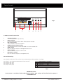
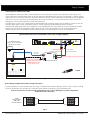
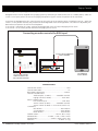
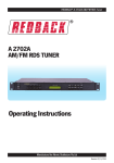
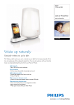
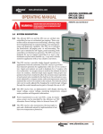
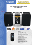
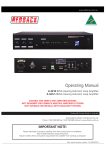
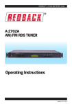
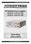
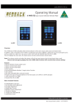
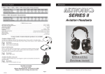
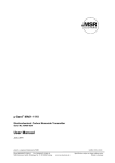
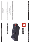
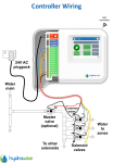
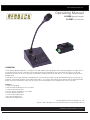
www.altronics.com.au
Operating Manual
A 4486 Paging Console
A 4487 Line Out Box
OVERVIEW
The A 4486 paging microphone is a simple to use and elegant desk top design which provides paging to a single zone. A
pre-announcement chime is available at the paging console and through the PA system. Both of these are set by DIP
switches on the rear of the unit. Provision has also been made on the rear of the unit for a 3.5mm BGM input for background music.
The A 4487 Line out box provides a MIcrophone or Line level output which can be connected directly to the input of an
amplifier. Connection between the A 4486 and A 4487 is via a Cat5e cable which carries power and the balanced audio
output from the microphone. Power for the system can be connected at the microphone or the Line Out box.
Features
• Single zone paging.
• High level balanced output via Cat 5 cable
• 3.5mm BGM input on rear
• 24V DC power supplied via Cat 5 cable
• Pre-announcement chime.
• Chime volume adjustment
• Mic volume adjustment
• BGM volume adjustment
Distributed by Altronic Distributors Pty. Ltd.
Phone: 1300 780 999 Fax: 1300 790 999 Internet: www.altronics.com.au
Redback® Proudly Made In Australia
User manual revision number: 1.1 20/02/2015
Paging Console
24VDC In
DIP Switches 1-2 Settings
On
SW
Off
PA System Chime Off
1 PA System Chime On
Internal Chime Off
2 Internal Chime On
BGM
Input
BGM Chime Mic
Volume Volume Volume
Fig 1
ON
1 2 3 4
1 2 3 4
1
2
3
4
5
6
7
A 4486 Rear Panel Connections
1
2
3
4
5
6
7
24V DC connector
2.1mm DC jack (centre pin positive).
RJ45 connector
For connection back to the A 4487. Either port can be used.
DIP switch options
These switches set the chime options.
BGM (Background Music) Input
The background music can be connected via a 3.5mm Stereo Jack.
BGM volume
Use this volume to adjust the background music level.
Chime volume
Use this volume to adjust the chime level.
Microphone volume
Use this volume to adjust the microphone level.
DIP Switch Settings
DIP switches on the rear of the unit set the Pre-announcement chime options. (See Fig 2)
DIP switch 1 sets the pre-announcement chime on or off.
DIP switch 2 Not used.
DIP switch 3 Not used
DIP Switch 4 Not used
DIP Switches 1-4 Settings
On
SW
Off
1 Pre-announce Chime On Pre-announce Chime Off
Not used
2
3
Not used
4
Not used
Fig 2
IMPORTANT NOTE:
Ensure power is switched off when adjusting DIP switches. New settings will be effective when power is
switched back on.
2 Redback® Proudly Made In Australia
www.altronics.com.au
Paging Console
Connecting the A 4486 and A 4487
The Microphone and Line out box are connected by a CAT5e cable with a maximum run distance of 300 metres. This
CAT5e cable can be connected to either of the two RJ45 ports provided on the rear of the microphone. A 24V DC power
supply rated at a minimum of 500mA is required to power the system. Power connection can be made at the microphone
itself via a 2.1mm DC Jack or by connecting power to the Line Out Box via a 2 way screw terminal. Power is then fed
through the CAT5e cable to feed the system from either end.
If powering the system at the A 4486 end we recommend fitting the power supply with the Altronics P 0602 2.1mm DC
Plug with collar which can be screwed onto the DC socket to prevent accidental disconnection of power.
The balanced audio output from the microphone is transmitted down the CAT5e cable to the Line Out Box which splits
and converts the signal to microphone and line level outputs. These are provided as screw terminal connections.
Volume controls for the microphone volume and chime volume are located on the rear of the microphone.
Typical connection of the A 4486 and A 4487 with a single amplifier
Input 1
AC Fuse (M 205)
Output
24V DC POWER SUPPLY
SUCH AS M 9391A PLUGPACK
OR SIMILAR 24V SUPPLY.
30W
Fuse
100V
OUT
1 Amp
60W
2 Amp
100W
4 Amp
CAUTION
RISK OF ELECTRIC SHOCK
OPEN BY QUALIFIED
PERSONNEL ONLY
Table 1 : DIP Switch Settings
SW
1-6,8
Not Used
SW
!
7
Input
Line input
Input Senitivity
1V 300mV
On
Off
+
2
3
4
5
6
7
8
+ _
+ _
HOT
GND
COLD
LINE OUT
24V DC
IN
A 4486 Communicator
1
Balanced
Input
Sensitivty
Fuse
3 Amp
5 Amp
7.5 Amp
24V DC
IN
Balanced
Balanced Input
Configuration
2
1
3
Resettable DC FUSE
Mic
(3mV)
Line
30W
60W
100W
Manufactured in Australia By
Altronic Distributors Pty. Ltd.
www.altronics.com.au
1 • Shield
2 • Hot
3 • Cold
Line
(2V)
-
+
MIC LEVEL SIGNAL
(TO MIC IN ON AMPLIFIER)
A 4487 Line Out Box
MIC OUT
TO PAGING
CONSOLE
POWER CAN BE CONNECTED
EITHER AT THE A 4486 PAGING
MICROPHONE OR AT THE
A 4487 LINE OUT BOX.
Output
2
R
LINE LEVEL SIGNAL
(TO LINE IN ON AMPLIFIER)
CAT5 cable
Max 300M
Volume
3
1 2 3 4 5 6 7 8
1
-
L
DIP Switches
(Refer to table1)
+ _
240VAC @ 50Hz
HOT
GND
COLD
NOTE: ONLY ONE OUTPUT SHOULD BE USED
Lock On
System Busy
P 0602
Page
Fig 3
RJ45 cabling configuration (586A ‘Straight through’)
System components are connected using “pin to pin” configuration RJ45 data cabling as shown in fig 4. When installing
ensure all connections are verified with a LAN cable tester before switching any system component on.
Failure to follow the correct wiring configuration may result in damage to system components.
and will Void the warranty.
586A
Straight Through
(both ends)
Pins Face Upwards
1 TX+
2 TX3 RX +
4
5
6 RX7
8
1 TX+
2 TX3 RX +
4
5
6 RX7
8
Fig 4
www.altronics.com.au
Redback® Proudly Made In Australia
3
Paging Console
Activating the BGM (Background Music)
Backgound music can be supplied to the paging system by connecting an audio source such as a mobile phone, tablet etc.
to the 3.5mm input jack on the rear of the paging microphone. Figure 5 shows the position of this connector.
To activate the background music, move the push to talk switch to the up position which is lablelled “Lock On”. While the
switch is in this position and only this position will the background music will be piped out. The volume is adjusted by the
BGM volume trimpot on the rear of the microphone.
If the switch is moved to the “Page” position the background music will stop and paging will be active.
If the switch is in the centre position the BGM and paging are not active.
Connecting an audio source to the BGM input
ADJUST THE BACKGROUND
MUSIC VOLUME
A 4486 Communicator
Lock On
System Busy
Page
24VDC In
DIP Switches 1-2 Settings
On
SW
Off
PA System Chime Off
1 PA System Chime On
Internal Chime Off
2 Internal Chime On
BGM
Input
BGM Chime Mic
Volume Volume Volume
ON
1 2 3 4
1 2 3 4
TO ACTIVATE THE BGM
MOVE THE SWITCH TO
THE “LOCK ON” POSITION
REAR OF A 4486
BACKGROUND
MUSIC SOURCE
Fig 5
SPECIFICATIONS
OUTPUT MIC LEVEL:.......................................................3mV
OUTPUT LINE LEVEL:.........................................................1V
BGM INPUT SENSITIVITY:...........................................500mV
OUTPUT CONNECTORS:
Audio Outputs: (A 4487).............Euroblock terminal
Paging Console (A 4486):....................... RJ45 8P8C
INPUT CONNECTORS:
Line Out Box Input:................................. RJ45 8P8C
24V DC Power (A 4487):.............Euroblock terminal
24V DC Power (A 4486):..2.1mm JACK (centre +ve)
CONTROLS:
Mic Volume:.........................................Rear Volume
Chime Volume:.....................................Rear Volume
BGM Volume:.......................................Rear Volume
POWER SUPPLY:......................................24V DC @ 0.5 Amp
DIMENSIONS:≈..................... A 4486 - 117W x 135D x 350H
DIMENSIONS:≈............................A 4487 - 90W x 52D x 30H
WEIGHT: ≈....................................................A 4486 - 0.7 kg
4 Redback® Proudly Made In Australia
www.altronics.com.au