1
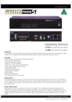
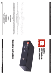
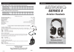
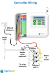
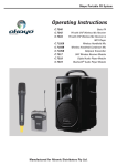
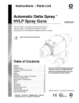
www.altronics.com.au
Operating Manual
A 1708 50 Event 4 Output 24 Hour 7 day Timer
Redback® Proudly Made In Australia
Distributed by Altronic Distributors Pty. Ltd.
Phone: 1300 780 999 Fax: 1300 790 999 Internet: www.altronics.com.au
IMPORTANT NOTE:
Please read these instructions carefully from front to back prior to installation.
They include important setup instructions.
Failure to follow these instructions may prevent the unit from working as designed.
User manual revision number: 1.0 13/05/2015
1.0 OVERVIEW
The A 1708 is a versatile timer which has four switched 24V DC outputs and four closing contacts which activate
simultaneously. It permits a total of 50 station (event) switching times. Each can be set to turn on any single day of the
week or on multiple days, from 1 sec up to 24 hours. Switching events programmed for multiple days count as only a
single station (event) and each of the 50 event times may be set to any (but not multiple) output.
Manual override is provided so that any of the four outputs can be set “ON” or “OFF” manually which overrides any of
the event times programmed for that output.
The unit has security lock out of Time Edit, Station Edit and Clear Memory Functions via DIP switch selections on the rear
of the unit.
2.0 OPERATION
On the front of the timer there are 3 groups of LED’s which provide a visual indicator of the status of each of the four
output zones. The red LED’s indicate a zone is in “Auto” mode and therefore the output of that zone will be controlled by
whatever event times have been programmed into the timer. The green LED’s indicate that a zone is in “Manual” mode
and therefore has been manually set to be either “ON” or “OFF” by the user. Once a zone is in “Manual” mode it will stay
in this mode until the user sets it back to “Auto” mode. The amber LED’s indicate the output status of the zone.
On the rear of the unit are the 24V DC switched outputs and four sets of closing contacts. If a zone is set to “ON” the
corresponding switched output will become active and 24V DC will be present at the terminals. At the same time the
closing contact for that zone will short, and stay that way until the zone is again set “OFF”.
(NOTE: the 24V DC outputs switch the voltage supplied to the unit via the 24V DC input connector. Therefore the output
voltage is determined by the voltage supplied to power the unit).
In order to setup the unit to run automatically, the station (or event) times will need to be programmed. There are five
buttons on the front of the timer which are used to program the unit and navigate the various menus.
SPECIAL NOTE ABOUT “AUTO MODE” OPERATION
If the timer is not displaying the main clock screen, where the time is changing, the unit is
not running in “Auto Mode”. This means it will not be checking any of the programmed
events and hence will not activate any outputs automatically.
Essentially this means that as soon as the Menu button is pressed the unit is no longer in
“Auto Mode”.
Make sure to return to the main screen by exiting all menu’s when not making changes.
3.0 NAVIGATING THE MENUS
When the unit is first powered up, the model number and Chipset will be displayed briefly before the current time is
shown.
Altronics A 1708
DS3231 Chipset 1
Fig 3.1
The main screen (Current Time Screen) shown in Fig 3.2 displays the current time. When this screen is displayed the unit
is running in “AUTO MODE” and therefore all outputs will work as programmed. However if the unit is in any of the sub
menu’s (Menu Mode) the unit will no longer respond to any event that has been programmed to occur, while the unit
remains in menu mode. On exiting the menu, the timer will check all programmed events and update the status of the
output zones.
Monday
07:00:00
2 Redback® Proudly Made In Australia
Fig 3.2
www.altronics.com.au
Press the “Menu” button on the front of the timer. The unit is now in “Menu Mode” and the screen should display the
Manual Select of Output Zones Screen. This is the first of 5 sub menu screens which are navigated by pressing the up and
down buttons as shown in Fig 3.3. Pressing the Menu button again will return the user to the Main Screen. Select the
desired sub menu by pressing the “Enter” button.
Main Screen
Monday
07:00:00
Menu
1) Manual select
of output zones
2) Add or edit a
Station time
Press the UP and DOWN
buttons to scroll up and
down.
Enter
Menu
Fig 3.3
3)
Edit time
on clock
Press the ENTER
button to make your
selection
Press the MENU
button to exit at any
time.
4) Clear memory
of ON/OFF times.
5) Exit Main Menu
3.1 SUB MENU’S
There are 4 options to choose from.
1) Manual Selection Of Output Zones
2) Add or Edit A Station Time
3) Edit Time on Clock
4) Clear Memory of ON/OFF Times
3.1.1 Manual Selection OF Output Zones
After selecting this option the screen should appear as shown in Fig 3.4. The square brackets indicate the cursor position
on the screen.
OUTPUT 1
[AUTO] ON
OFF
www.altronics.com.au
Fig 3.4
Redback® Proudly Made In Australia
3
To set a Zone manually, scroll to the desired zone using the up and down buttons as shown in Fig 3.5 and then press
“Enter” when you reach your selection. When finished scroll to the “Exit Manual Zone Selection” screen and press
“Enter” or press the “Menu” button to exit at any time. (NOTE: For the unit to continue in “AUTO MODE” you must exit
back to the Main Screen.)
SPECIAL NOTE:
If power is removed, all outputs will switch off and all zones will
return to Auto mode once power is restored.
Exit Manual
Zone Selection
Manual Selection Screen
1) Manual select
of output zones
Enter
OUTPUT 1
[AUTO] ON
OFF
OUTPUT 3
[AUTO] ON
OFF
OUTPUT 1
AUTO [ON]
OFF
OUTPUT 3
AUTO [ON]
OFF
OUTPUT 1
AUTO ON
[OFF]
OUTPUT 3
AUTO ON
[OFF]
Press the UP and DOWN
buttons to scroll up and
down.
Enter
Menu
Press the ENTER
button to make your
selection
Press the MENU
button to exit at any
time.
Fig 3.5
OUTPUT 2
[AUTO] ON
OFF
OUTPUT 4
[AUTO] ON
OFF
OUTPUT 2
AUTO [ON]
OFF
OUTPUT 4
AUTO [ON]
OFF
OUTPUT 2
AUTO ON
[OFF]
OUTPUT 4
AUTO ON
[OFF]
3.1.2 Add or Edit A Station Time
This option allows the user to enter the Station (Event ) information which includes the event “Turn on time”, “Duration”
and “Output Zone”.
If this is the first time an Event has been entered the memory will need to be “Cleared” first. To do this follow the
directions in the section “Clearing the Memory”.
SPECIAL NOTE FOR FIRST TIME USE:
When powering up the unit for the first time it will be necessary to
clear the memory before entering any Station (Event) times. If this is not
done the unit will not operate correctly. To do this use option 4 in the
menu. Refer to the section on “Clearing the Memory”.
Navigate to the “Add or Edit a Station Time” Sub Menu as shown in Fig 3.3. If this is the first time entering this menu the
screen should appear as shown in Fig 3.6. The number “1)” shown is the Station (or Event) number which is highlighted
by a flashing cursor.
1) DAY
Start @ 00:00:00
4 Redback® Proudly Made In Australia
Fig 3.6
www.altronics.com.au
From this point the user can scroll through all 50 stations using the up and down buttons as shown in fig 3.7. This makes
it very easy to view all Station time settings at a glance. Once the station number desired is shown on the LCD press the
“Enter” button to confirm and move to the next step which is to make changes to the station “day”.
50) DAY
Start @ 00:00:00
Station (or Event) number
2) Add or edit a
Station time
+10
Enter
Press the +10 button to
scroll up 10 stations
Press the UP and DOWN
buttons to scroll up and
down.
Enter
Menu
1) DAY
Start @ 00:00:00
2) DAY
Start @ 00:00:00
Fig 3.7
3) DAY
Start @ 00:00:00
Press the ENTER
button to make your
selection
Press the MENU
button to exit at any
time.
49) DAY
Start @ 00:00:00
The DAY represents the day of the week that the Event will take place and can be any day from Monday to Sunday or
one of many multiple day options which are listed below. Pressing the up and down buttons will scroll through the days
monday to friday and then through the multiple days.
Mon-Fri
Sat-Sun
Mon/Wed/Fri
Tue/Thu/Sat
Mon-Thur
Mon-Sun
Tue-Fri
Mon/Fri
Tue/Wed/Thu
Mon/Wed
Mon/Thur
Mon/Tue/Thu
Tue/Thur
Tue/Wed/Fri
Tue/Thu/Fri
Wed/Fri
Mon/Tue/Wed
Day of the week
1)
DAY
Start @ 00:00:00
1)
Mon/Tue/Wed
Start @ 00:00:00
1)
Monday
Start @ 00:00:00
1)
Tuesday
Start @ 00:00:00
Fig 3.8
Press the UP and DOWN
buttons to scroll up and
down.
Enter
Menu
Press the ENTER
button to make your
selection
1)
Wednesday
Start @ 00:00:00
Press the MENU
button to exit at any
time.
1) Wed/Fri
Start @ 00:00:00
Once the day or multiple days desired is shown on the LCD, press the “Enter” button to confirm. The cursor will now
move to the start time. This is the time the “Event” is to take place and is in 24 hour format.
www.altronics.com.au
Redback® Proudly Made In Australia
5
The cursor is now positioned over the hour section of the start time as shown in Fig 3.9.
Change the hour by pressing the +10, up and down
buttons and press “Enter” when finished. The cursor
will now move to the minute section of the start time.
Repeat the above procedure to change the minutes
and press “Enter” when finished. The cursor will now
move to the seconds section of the start time. Repeat
the above procedure again to change the seconds and
press “Enter” when finished. The start time is now set
for this Station (or Event).
After completing the start time, the screen will change
to the Zone and Duration options screen as shown in
Fig 3.10.
Start time
1)
Monday
Start @ 00:00:00
+10
Press the +10 button to
scroll up 10
hours/min/secs
Press the UP and DOWN
buttons to change the
hour/min/secs.
Enter
1) ZONE
OFF
DURATION
00:00:00
Menu
Fig 3.10
1)
Monday
Start @ 23:00:00
1)
Monday
Start @ 00:00:00
1)
Monday
Start @ 01:00:00
1)
Monday
Start @ 02:00:00
Press the ENTER
button to make your
selection
Press the MENU
button to exit at any
time.
1)
Monday
Start @ 22:00:00
Fig 3.9
From this point the user can scroll through all 50 stations using the up and down buttons as shown in fig 3.11. This makes
it very easy to view all Output Zone settings at a glance. Once the station number desired is shown on the LCD press the
“Enter” button to confirm and move to the next step which is to make changes to the zone output.
50) ZONE DURATION
OFF
00:00:00
Station (or Event) number
1) ZONE
OFF
+10
DURATION
00:00:00
Enter
Press the +10 button to
scroll up 10 stations
Press the UP and DOWN
buttons to scroll up and
down.
Enter
Menu
1) ZONE
OFF
DURATION
00:00:00
2) ZONE
OFF
DURATION
00:00:00
Fig 3.11
3) ZONE
OFF
DURATION
00:00:00
Press the ENTER
button to make your
selection
Press the MENU
button to exit at any
time.
6 Redback® Proudly Made In Australia
49) ZONE DURATION
OFF
00:00:00
www.altronics.com.au
Fig 3.12 illustrates the Zone Output setup procedure. There are 4 output zones to choose from. Use the up and down
buttons to change the zone output and press “Enter” when finished. The zone can also be set to “OFF” which will turn
this output off, but not affect the time settings so that it can easily be re-initiated by setting the zone output later.
Zone Output
Press the UP and DOWN
buttons to change the
zone output.
Enter
Menu
Press the ENTER
button to make your
selection
Press the MENU
button to exit at any
time.
1) ZONE
OFF
DURATION
00:00:00
1) ZONE
1
DURATION
00:00:00
1) ZONE
2
DURATION
00:00:00
1) ZONE
3
DURATION
00:00:00
1) ZONE
4
DURATION
00:00:00
Fig 3.12
The cursor is now positioned over the hour section of the Zone Duration as shown in Fig 3.13. The duration is the amount
of time the event will occur for, after the start time.
Change the hour by pressing the +10, up and down
buttons and press “Enter” when finished. The cursor
will now move to the minute section of the duration.
Repeat the above procedure to change the minutes
and press “Enter” when finished. The cursor will now
move to the seconds section of the duration. Repeat
the above procedure again to change the seconds and
press “Enter” when finished. The menu button can be
pressed at any time to exit the setup. The duration is
now set for this Station (or Event).
After completing the duration, the screen will change to
the next station ready to enter the next events details.
Zone Duration
1) ZONE
1
+10
NOTE: IF the duration is set to 00:00:00 the zone
output will be set back to “OFF” on exiting the “Set
Duration” screen.
DURATION
00:00:00
Press the +10 button to
scroll up 10
hours/min/secs
Press the UP and DOWN
buttons to change the
hour/min/secs.
Enter
Menu
1) ZONE
1
DURATION
23:00:00
1) ZONE
1
DURATION
00:00:00
1) ZONE
1
DURATION
01:00:00
1) ZONE
1
DURATION
02:00:00
1) ZONE
1
DURATION
22:00:00
Press the ENTER
button to make your
selection
Press the MENU
button to exit at any
time.
Fig 3.13
www.altronics.com.au
Redback® Proudly Made In Australia
7
3.1.3 Edit the Clock Time
This option sets the current time.
After selecting the “Edit Time on Clock” option from
the menu shown in Fig 3.3 the LCD will display the
screen shown in Fig 3.13 where the cursor flashes on the
current day.
Clock Day
3)
Edit time
on clock
Pressing the up and down buttons will scroll through the
days Monday to Sunday. Pressing “Enter” will confirm
the day and then move the cursor to the hour option as
shown in Fig 3.14.
Change the hour by pressing the +10, up and down
buttons and press “Enter” when finished. The cursor
will now move to the minute section of the clock time.
Repeat the above procedure to change the minutes
and press “Enter” when finished. The cursor will now
move to the seconds section of the clock time. Repeat
the above procedure again to change the seconds and
press “Enter” when finished. The menu button can be
pressed at any time to exit the setup. The clock time is
now set.
After completing the clock time, the screen will change
to the current time.
Sunday
00:00:00
Enter
Monday
00:00:00
Tuesday
00:00:00
Press the UP and DOWN
buttons to change the
day.
Enter
Edit
Edit
Edit
Wednesday
00:00:00 Edit
Press the ENTER
button to make your
selection
Menu
Press the MENU
button to exit at any
time.
Saturday
00:00:00
Edit
Fig 3.13
Clock Time
+10
Press the +10 button to
change the
hour/min/secs.
Press the UP and DOWN
buttons to change the
hour/min/secs.
Enter
Menu
Monday
23:00:00
Edit
Monday
00:00:00
Edit
Monday
01:00:00
Edit
Monday
02:00:00
Edit
Monday
22:00:00
Edit
Press the ENTER
button to make your
selection
Press the MENU
button to exit at any
time.
Fig 3.14
8 Redback® Proudly Made In Australia
www.altronics.com.au
3.1.4 Clearing the Memory
This function will clear the internal memory, erasing any information entered.
IMPORTANT NOTE:
The memory must be cleared before using the unit for the first time.
Navigate to the “Clear Memory of ON/OFF times” Sub Menu as shown in Fig 3.3.
Press “Enter” to activate this option. If DIP switch 4 is set to “ON” the screen will display the message shown in Fig 3.15.
Not Available
Check Settings
Fig 3.15
This is one of the security options to protect the information stored in memory. See the DIP Switch settings for more
information. Set the DIP switch 4 to “OFF” and then press “Enter” again. This time you should enter the Clearing the
Memory Sub Menu. The following two screens should be briefly displayed.
This will clear
all ON/OFF times
Are you sure?
Then you will be asked to press “Enter” to confirm you want to clear the memory or press “Menu” to exit.
Hold ENTER for Y
or MENU for No
If you press Menu you will return to the Clear Memory Sub Menu.
If you press Enter, the unit will cycle through the memory locations clearing any data stored. This will take a few minutes.
Once finished you will return back to the Clear Memory Sub Menu.
NOTE: It is advisable to now set DIP switch 4 to “ON” to prevent accidental clearing of the memory.4.0 DIP SWITCH SETTINGS
IMPORTANT NOTE:
Ensure power is switched off when adjusting DIP switches.
New settings will be effective when power is switched back on.
There are four DIP switches accessible on the rear of the A 1708 which are for selecting the backup battery and various
security lockout features (See Fig 4.1).
Switch 1 - Battery Backup
When switch 1 is set to the “ON” position the internal battery is connected to the units clock chip. If power is
ever
removed the battery will ensure the clock chip continues to run and therefore keep the current time.
NOTE : This battery does not provide backup power to the entire A 1708 unit. The display will not light up and
the unit will not function. Only the internal clock chip will still be supplied power.
If the entire A 1708 requires backup power a backup power supply can be connected to the 24V DC input.
DIP Switch Settings
SW ON
1
Battery Backup On
2
Station Edit Lockout Enabled
3
Edit Time Lockout Enabled
4
Clear Memory Lockout Enabled
www.altronics.com.au
Fig 4.1
Redback® Proudly Made In Australia
9
Switch 2 - Station Edit Lockout
When switch 2 is set to “ON” access to the Station Edit Mode will be restricted. Therefore there can be no tampering
of the Station (Event) times.
Switch 3 - Time Edit Lockout
When switch 3 is set to the “ON” access to the Time Edit Mode will be restricted. Therefore there can be no changes
made to the current time.
Switch 4 - Clear Memory Lockout
When switch 4 is set to the “ON” access to the Clear Memory Mode will be restricted. Therefore there can be no
erasing of the Station (Event) times stored in memory.
5.0 BATTERY BACKUP
Inside the unit is the battery used to backup the internal clock chip. If DIP switch 1 is set to “ON” and the unit fails to keep
the correct time after a power failure then it may be possible that the backup battery is flat. To replace the battery, remove
the lid and use a CR2032 battery (such as Altronics S 4999A) as the replacement. The location of the battery is shown in
Fig 5.1.
The backup battery is
located inside the unit
and can be accessed by
removing the lid.
Fig 5.1
Battery type CR2032
Altronics P/No: S 4999A
6.0 REAR CONNECTIONS
6.1 24V DC Connectors
DC sockets have been provided for 24V DC input and a 24V DC output. These two sockets are connected in parallel inside
the unit, so either could be used as an input or output or both as inputs. Two sockets have been provided so that the
power can be daisy chained to another device. The Altronics P 6717 DC power lead has been designed for this purpose.
The sockets also have a threaded connector so that the Altronics P 0602 2.1mm DC Plug with collar can be screwed onto
the DC socket so that the DC power lead cannot be accidentally pulled out.
P 0602
2.1mm DC Plug with collar
Fig 6.1
6.2 DC Fuse
The A 1708 is fitted with an M205 fuse holder with fuse rated at 2A.
6.3 Interface 1 and Interface 2
These are for future connection of product. Do not connect leads to these ports.
10 Redback® Proudly Made In Australia
www.altronics.com.au
6.4 Switched 24V Outputs:
These terminals have 24V DC present when the corresponding zone is set “ON”.
These may be used to operate something like an external relay used to turn on a solenoid, a lunch bell, etc.
(NOTE: The maximum current draw per output is about 120 milliamps (internally polyswitch protected), so it is advisable
to run external 24V DC relays instead of trying to drive a 24V DC device directly from these outputs. See Fig 6.2 for an
example of this).
6.5 Closing Contacts:
These contacts “close” when the output zone is set “ON”. These can be used to trigger devices such as the Altronics
A 1741MP3 Message player.
Line Out
+
+
-
–
Cancel Evac Alert
8
7
3
4
2
1
1
0
1
0
0
1
1
1
0
1
1
0
1
1
1
1
1
1
1
1
450
0
1
0
1
360
1
0
0
1
420
0
0
0
1
330
1
1
1
0
390
0
1
1
0
300
90
5
1
0
1
0
270
60
6
0
0
1
0
240
1
1
0
0
210
0
1
0
0
180
1
0
0
0
150
0
0
0
0
DIP Switches
Close
Contacts
to
Trigger
1
2
3
4
5
6
7
8
1 2 3 4 5 6 7 8
www.altronics.com.au
Triggers
R
AUTO ALERT TO EVAC SWITCHOVER TIMER SETTINGS. 0 = OFF. 1 = ON.
120
L
DIP Switch Settings
SW
TRIGGER OPERATION & ALERT/EVAC SETTINGS
5
SW
ON
OFF
6
Triggers alternate
1 Triggers momentary
7
2
Alert/Evac OFF
Alert/Evac ON
8
Front switches active Front switches de-activated
3
Delay
(Sec.)
4
Not Used
30
12-30V DC
Switched
Out
OFF
12-30V DC
IN
Manufactured in Australia
By Altronic Distributors Pty. Ltd.
Fig 6.5 demonstrates an example of how to connect the A 1708 to the A 1741. A 24V DC plugpack is used to power the
A 1708, the 24V DC output of the timer is then fed into the A 1741 using a power lead with 2.1mm DC connectors such
as the Altronics P 6717. Thus removing the need for another plugpack to power the message player.
The Zone 1 switched output of the timer is then used to trigger a 24V DC bell. As the current draw of the Bell is more
than 120mA a relay board is used to switch an external power supply. The Altronics S 4444 24V Relay Board as shown is
an inexpensive and easily installed option designed for this purpose.
In the example shown the Zone Output 2 closing contact of the timer is connected to the Input 1 trigger of the message
player. When Zone 2 is activated by the timer, message 1 of the message player will be played.
A 1741
MP3 Message Player
24V DC Power lead
(such as Altronics P 6717)
(Not supplied)
Manufactured in Australia
By Altronic Distributors Pty. Ltd.
DC Fuse 24VDC
Input
24VDC
Output
Interface 1
Interface 2
24V Switched Out
4
3
2
DIP Switch Settings
SW ON
1
Battery Backup On
2
Station Edit Lockout Enabled
1 3 Edit Time Lockout Enabled
4
Clear Memory Lockout Enabled
DIP Switches
1
+ -
+
www.altronics.com.au
4
3
2
2
3
4
5
6
7
8
+ _ + _ + _ + _
M205 2 Amp
A 1708
50 EVENT TIMER
1
+24V
GND
External
24V DC Supply
N/C1
COM1
N/O1
N/C2
COM2
N/O2
+24V
GND
24V DC Plugpack
(such as Altronics M 9391A)
24V Relay Board
(Altronics S 4444)
24V Bell
(eg school bell, lunch bell etc)
Fig 6.5
www.altronics.com.au
Redback® Proudly Made In Australia 11
7.0 EVENT TIMES RECORD
A sheet has been provided to record all of the Event(s) information for easy reference.
OUTPUT 1 =
OUTPUT 2 =
OUTPUT 3 =
OUTPUT 4 =
STATION
1
2
3
4
5
6
7
8
9
10
11
12
13
14
15
16
17
18
19
20
21
22
23
24
25
26
27
28
29
30
31
32
33
34
35
36
37
38
39
40
41
42
43
44
45
46
47
48
49
50
OUTPUT
12 Redback® Proudly Made In Australia
DAY
TURN ON TIME DURATION TURN OFF TIME
www.altronics.com.au