Download User`s Manual
Transcript
3
COM
8
10
9
Relay
AL2 5
AL3 4
COM 7
Alarm 2 output
Alarm 3 output
Common
Relay contact rating: 240 V AC, 1 A
30 V DC, 1 A (resistance load)
AL1 6
Alarm 1 output
Alarm output
Before carrying out wiring, turn off the power to the
indicator and check that cables to be connected are
not alive with a tester or the like because there is
a possibility of electric shock.
CAUTION
Allowable range: 100 to 240 V AC (⫾10%)
(free voltage)
50/60 Hz shared
N
L
SG
27
UM
Common
Resets the PV
peak and bottom values
when DI1 is changed
from OFF to ON.
UM
DI1 19
12 +
13 -
4-20 mA DC
+5V
COM
DI1
17 -
16 +
20
19
NOTE
* If 15 V DC loop power supply is used,
retransmission output cannot be used.
Load resistance: 600 Ω or less
䊏 Receiving 4-20 mA DC Current
Signals with the Indicator
250 Ω 4-20mA
Note: Connecting a 250 Ω resistor to the terminals is
optional.
Model: X010-250-2 (resistor with M3.5 crimp-on
terminal lugs)
13 -
12 +
* When receiving 4-20 mA DC current signals,
set the PV input type to 1-5 V DC (setpoint 41 ).
Correction
Installation category (overvoltage category): II (IEC1010-1)
* PV retransmission is configured at factory
before shipment.
Transistor contact
14.5-18.0VDC
(21 mA DC max.)
15 V DC loop power supply
17 -
16 +
13 -
12 +
mV/V input
13 B
12 b
11 A
RTD input
* Not configured at factory before shipment
See Initial Settings User’s Manual ,
for more information.
TC input
PV input
Retransmission output
Contact rating: 12 V DC, 10 mA or more
Contact
Contact input
21.6-28.0VDC
(30 mA DC max.)
COM 20
20
10
17
19
27
16
13
12
11
22 -
21 +
* Wiring can only be carried out
for indicators with 24 V DC
loop power supply.
24 V DC loop
power supply
9
8
7
26
25
5
6
23
24
3
22
4
21
1
2
* Wiring can only be carried out
for indicators with communication
functions.
Maximum baud rate: 9600 bps
IM 05F01D02-01E-S01
Power supply
Power supply
RDA(-)
26
* Wiring can only be carried out for
UM350-ⵧ1 or UM350-ⵧ2.
Contact rating: 250 V AC, 3 A
30 V DC, 3 A (resistance load)
1
2
NC
NO
Relay contact output
Alarm 4 output
SDA(-)
25 RDB(+)
24
23 SDB(+)
RS-485 communication
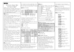
■ Model UM350 Digital Indicator with Alarms -Terminal Wiring-
User’s
Manual
Models UM350/UM330
Digital Indicator with Alarms
User’s Manual
Supplement
This supplement is for the 1st edition of "Models UM350/UM330 Digital Indicator with
Alarms"(IM05F01D02-41E).
This supplement provides with an error correction.
IM 05F01D02-01E-S01
2000.8
250 Ω 4-20mA
13 -
12 +
- 22
3
COM
Contact rating: 250 V AC, 3 A
30 V DC, 3 A (resistance load)
2
NO
11 12 13
AL3 4
Alarm 3 output
Common
AL2 5
Alarm 2 output
Relay contact rating: 240 V AC, 1 A
30 V DC, 1 A (resistance load)
Relay
COM 7
AL1 6
Alarm output
Alarm 1 output
UM
4
5
8
10
8
10
9
+5V
COM
DI1
Contact rating: 12 V DC, 10 mA or more
COM 20
Contact
Contact input
UM
DI1 19
SG
27
for indicators with communication
functions.
Maximum baud rate: 9600 bps
Before carrying out wiring, turn off the power
to the indicator and check that cables to be
connected are not alive with a tester or the like
because there is a possibility of electric shock.
CAUTION
RDA(-)
25
26
SDA(-)
RDB(+)
24
23 SDB(+)
RS-485 communication * Wiring can only be carried out
Common
Resets the PV
peak and bottom values
when DI1 is changed
from OFF to ON.
* If 15 V DC loop power supply is used,
retransmission output cannot be used.
Load resistance: 600 Ω or less
* PV retransmission is configured at factory
before shipment.
Correction
Allowable range: 100 to 240 V AC (⫾10%)
(free voltage)
50/60 Hz shared
N
L
Power supply
9
19 20
14.5-18.0VDC
(21 mA DC max.)
Power supply
6
7
3
1
2
27
21 22 23 24 25 26
16 17
16 +
17 -
13 -
Relay contact output * Wiring can only be carried out for
UM330-ⵧ1 or UM330-ⵧ2.
NC
1
Alarm 4 output
21.6-28.0VDC
(30 mA DC max.)
+ 21
* Wiring can only be carried out
for indicators with 24 V DC
loop power supply.
24 V DC loop
power supply
4-20 mA DC
15 V DC loop power supply
17 -
16 +
Retransmission output
12 +
mV/V input
13 B
12 b
11 A
RTD input
* Not configured at factory before shipment
See Initial Settings User’s Manual ,
for more information.
TC input
PV input
Installation category (overvoltage category): II (IEC1010-1)
NOTE
Note: Connecting a 250 Ω resistor to the terminals is
optional.
Model: X010-250-2 (resistor with M3.5 crimp-on
terminal lugs)
13 -
12 +
* When receiving 4-20 mA DC current signals,
set the PV input type to 1-5 V DC (setpoint 41 ).
䊏 Receiving 4-20 mA DC Current
Signals with the Indicator
■ Model UM330 Digital Indicator with Alarms -Terminal Wiring-
20
19
Transistor contact
2
IM 05F01D02-01E-S01


