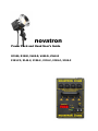
1
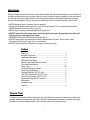
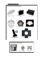
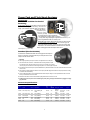
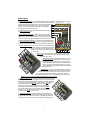
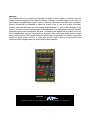
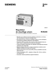
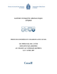
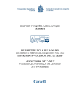
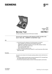
novatron Power Pack and Head User’s Guide D1500, D1000, V600-D, V400-D, V240-D 2103-FC, 2140-C, 2120-C, 2110-C, 2105-C, 2100-C Warning! Novatron Products are built with the finest components available, and engineered for performance and safety. Like all electronic devices which use high power loads of electricity, careless or improper handling can be quite hazardous and may cause injury. Please read this instruction manual carefully and thoroughly before using your new Novatron flash equipment. Failing to use proper procedure may result in voiding the warranty, injury or death. NEVER attempt to repair or open any Novatron products. All Novatron AC-power packs have a built in mechanical circuit breaker. This is an important safety feature. NEVER attempt to remove or modify it in any way. NEVER plug in or unplug flash heads while the ready light is on. ALWAYS remove from A/C power source and discharge the power pack by pressing the test button before plugging in or unplugging flash heads. NEVER touch the surface of the flashtube with bare hands. ALWAYS keep at least one (sometimes two) flash head switched to full power. See the section titled “Symmetrical Power Packs” (page 7) for more information. ALWAYS make sure all light connections and power connections are tight. Index Thank You .......................................................................................... 2 Available Accessories ......................................................................... 3 Fan Cooled Flash Head ...................................................................... 4 Switchable Flash Heads ..................................................................... 4 Standard (Non-Switchable flash heads) ............................................. 4 Flash Head Specifications .................................................................. 4 Power Packs.................................................................................... 5-6 General Operating instructions ........................................................... 6 Power Pack Specifications ................................................................. 6 Changing Reflectors (2103FC only).................................................... 6 Flash Tube Replacement (2103FC only) ............................................ 6 Internal Fan Information (2103FC only) .............................................. 6 Symmetrical Power Packs **Important ............................................... 7 Maintenance ....................................................................................... 7 Troubleshooting ................................................................................. 7 Warranty ............................................................................................. 8 Thank You! Thank you for purchasing Novatron Equipment. We realize that you have many choices when purchasing photography equipment and appreciate your trust in Novatron. Please take a few minutes to read this User’s guide thoroughly. It contains crucial information, that will ensure many years of reliable service. 2 Available Accessories Fits all Novatron Lighting equipment N7045W– Flash Umbrella (white) N4620– Coarse Honeycomb grid with gel holder N7450— Flash umbrella w/ silver reflective coating N4021—Gel Diffusion material kits N4001-A—Adjustable snoot N4001-A1—Honeycomb Grid for snoot NSC1– Standard soft case N4008— Diffusion materials N4011A— Adjustable barn doors Fits 2103-FC Fan cooled lights N2032— 6.5 inch reflector N2034— 16 inch reflector 3 Replacement flash tubes Power Pack and Flash Head Anatomy Flash Heads Fan Cooled and Non-fan Cooled Switching Flash Output Switch FLASH OUTPUT SELECTOR This switch is located on the rear of a switched head housing (for FC units see fig. 1 for non-FC unit see fig. 2) and controls the flash tube output. The up position is Modeling Light full power. The other two Output Switch (2) positions may be, Fig. 2 minus one (-1) f-stop, Fig. 1 minus two (-2) f-stops Flash Output Switch or "off" depending on model of switched flash head selected (some switching heads only allow for Modeling Light Output Switch -1 f-stop). When using multiple lights one light MUST be set to FULL power. When using ONE LIGHT ONLY use at FULL power. MODELING LIGHT OUTPUT SELECTOR This switch is located on the rear of a switched head (for FC units see fig. 1 for non-FC unit see fig. 2) and controls the modeling light output. It works in the same manner as the flash output selector. The luminance reduction is matched to that of the flash tube. Both the modeling light and the flash output controls can be used independently of each other. Standard (Non-Switchable) On Standard non-switchable flash heads the modeling light and flash output are always on at full power. These flash heads may be used by themselves or with multiple units. See restriction below. ***Important When using any Novatron power pack a minimum of one light MUST be set to full power. Fig. 3 The total maximum watt seconds of combined flash heads must be greater than or equal to the maximum power rating of the power pack you are using. For example if you are using a 1500 w/s power you need at least one 1500 w/s light at full power or two 1000 w/s lights at full power. Glass elements become extremely hot in operation! NEVER allow any flammable materials to come into contact with flash heads when the units are in use! When changing a modeling light bulb, ALWAYS turn off the power pack AND unplug the flash head from the power pack before touching the elements of the head assembly. Only the 2103FC flash head has a user-replaceable flashtube. Never attempt to change a non-user replaceable flash tube, this must be done by an authorized Novatron service center. NEVER cover the reflector end of the flash head with anything that blocks air flow when unit is in use. ALWAYS remove from A/C power source and discharge the power pack by pressing the test button before plugging in or unplugging flash heads. Flash Head Specifications Catalog No. Function Max W-S Special Features Cable Length User replaceable Flash Tube Modeling Lamp Reflectors Weight 2103FC Full/-1 stop/-2 stop 1500 3-way switching, fan cooled . 25 Foot Yes 250 Watt Halogen Lamp N2032 (6-1/2”) Removable 3.2 lbs. 2140C Full/-1 stop/-2 stop 1000 3-way switching 25 Foot No 100 Watt 6 1/2” fixed 3.0lbs. 2120C Full/-2 stop/off 1000 2-way switching 25 Foot No 100 Watt 6 1/2” fixed 2.2 lbs. 2110C Full/-1 stop/off 1000 2-way switching 25 Foot No 100 Watt 6 1/2” fixed 2.2 lbs. 2105C Full 1000 Non-switching 25 Foot No 100 Watt 6 1/2” fixed 2.2 lbs. 2100C Full 1000 Non-switching 15 Foot No 100 Watt 6 1/2” fixed 2.0 lbs. 4 Power Packs 1. RESET CIRCUIT-BREAKER— The circuit breaker protects the charging circuit of the power pack in case of malfunction. Rapid firing or continual firing of the pack over an extended period may overload the Models D1000 and D1500 transformer and trip the circuit breaker. This is caused by excessive heat build up within the transformer and associated circuits. If the circuit breaker trips, 1 wait one (1) minute before resetting and continuing. If it trips repeatedly, return the power pack to Novatron for service. 2 2. FLASH HEAD SOCKETS– This is where all 6-pin Novatron flash heads are plugged into the power pack. 3.FLASH VERIFICATION SWITCH— When this switch is in the on position if the power pack is told to fire and the flash head does not fire the “misfire” light will come on and the power pack will beep. This will also happen if the switch is on and there are no flash heads plugged into the flash head socket. 3 4 5 Fig. 4 4. FLASH FIRE VERIFICATION LIGHT— This light will come on indicating that the corresponding flash head did not fire or that there is nothing plugged into the flash head socket. This will only come on if the corresponding switch is in the on position. 5. FLASH POWER CONTROL—This control will evenly control the output of all flash heads attached to the power pack. Depending on which model power pack you have the control will either be a dial (fig. 5),an LCD readout with an up and down button (fig. 4) or a switch (fig. 6). M 6 2 6 od els 5 V4 00 -D ,V 7 8 9 10 6. READY LIGHT— This will light when the power pack has reached full charge. Recycle times will be faster for lower power settings selected by the flash power button, dial or switch. 10 60 0-D 7. TEST FIRE BUTTON—The test fire button has five main uses. 1) to calculate exposures with a Flashmeter. 2) to “dump” the circuit when changing power from high to low. 3) to “dump” the circuit if the ready light is still on but the power button is switched to the off position. 4) to check to see if your flashes are firing. 5) to create “special” flash effects by firing the flash at different or multiple times during a ling exposure. 1 7 8. SYNC SOCKET— Novatron power packs will interface with any two (2) prong style sync devices designed to plug into the socket. The Novatron 9 sync socket is electrically polarized, if a sync cord or a slave does not work when plugged into the power pack simply remove, rotate and plug back into Fig. 5 power pack. This receptacle is not a source of electrical power for other machines. NEVER plug your sync cord into an electrical wall outlet as serious injury may occur. 8 9. MODELING LIGHT SWITCH— This switch controls the modeling light of all heads plugged into the pack. This circuit is independent of the flash circuit. If this switch is in the off position. all of the modeling lights will be inoperative. If a modeling light failure occurs requiring lamp change, ALWAYS turn off the power pack AND unplug the flash head from the power pack before touching the elements of the head 6 assembly. Also if the unit has been in recent use be very cautious of han9 dling the glass elements as they get extremely hot in operation! NEVER allow any flammable materials to come into contact with flash heads when the units are in use! NEVER cover the reflector end of the flash head with anything that blocks air flow when unit is in use. 10. FLASH ON OFF SWITCH—This switch (or button) will turn off electricity going to the unit. Even though the switch is turned off there may still be an electrical charge in the unit even if the ready light is off. To discharge press the test fire button after unit is off and then wait 20 to 30 seconds before unplugging anything. 2 Mo de ls 7 5 8 1 10 Fig. 6 5 V2 40 -D General Operating Procedures 1. Plug in all the heads you require for your lighting situation. Never plug in flash heads while unit is plugged into A/C (wall ) power source. 2. Attach the power cord to the unit and plug into a grounded 120 V AC outlet. Press the power switch to the "on" position. 3. To use the modeling lights press the switch marked "model" to the "on" position. Use the modeling light to help you to pre-visualize your highlights and shadows. Use the switches on the flash heads to change lighting ratios and the power control on the power pack to change overall light intensity. See the section titled “Symmetrical Power Packs” for switching guidelines. 4. Press the test button to fire lights. 5. Connect power pack to your camera via sync cable or wireless syncing devices. Typical f/Stop STD. Head @ 10’/ISO 100 Typical Recycling Time Typical Guide Number STD. Head @10’/ISO 100 Outlets For Flash Heads Weight (lbs/ oz./) Size WxDxH (in Inches) Household Electrical Power Step Variable by 1/10 stop 1500 ws to 45 w-s Max 32+.5 min 8 Under 3 Sec at any setting 398 4 17 lbs. 6-3/8 x 10 x 7-5/8 120 VAC 15 AMP D1000 Step Variable by 1/10 stop 1000 ws to 45 w-s Max 32 min 5.6+5 Under 3 Sec at any setting 320 4 15.3 lbs 6-3/8 x 8-1/2 x 6-3/4 120 VAC 12 AMP V600D Infinitely Variable 600 W-S Max 22.25 min 5.6+5 Under 3 Sec at full 240 4 9 lbs. 6-3/8 x 8-1/2 x 6-3/4 120 VAC 6 AMP V400D Infinitely Variable 400 W-S Max 16+.8 min 5.6+5 Under 2.5 Sec at full 208 4 9 lbs 8 oz. 6-3/8 x 8 x 4-7/8 120 VAC 6 AMP V240D Switch to 120 or 240 W/S Max 11.7+ min 8+.4 Under 5 Sec at full 145 3 5 lbs. 8 oz. 5-3/8 x 6-1/4 x 4-3/4 120 VAC 4 AMP Catalog No. Power Selections D1500 Power Pack Specifications Changing Reflectors (2103FC Only) 1. 2. 3. 4. Loosen thumbscrews at the base of the reflector Rotate slightly counterclockwise. Gently remove. Be careful not to disturb the flash tube and modeling light bulb. Use the opposite procedure to put reflector back on. Flash Tube Replacement Procedure (2103FC Only) **Important**Only the 2103FC flash head has a user-replaceable flash tube. Do not attempt to change the flashtube of any other flash head unit, these flash tubes are non-user replaceable. If a non-user replaceable flashtube should need replacement return the unit to a Novatron authorized service center. Removal and replacement of the glass flash tube assembly requires no tools but we recommend using leather gloves for safety. Before attempting removal of the flash tube, unplug the unit and allow it to sit for at least 15 minutes 1. Remove the modeling lamp by unscrewing like any other standard bulb. 2. Wearing gloves, grasp the flash tube assembly carefully in one hand and the monolight housing in the other. Using a rocking motion, pull the flash assembly straight out from the mounting socket. DO NOT apply a lot of pressure to the glass envelope as this may cause the glass assembly to fracture. 3. To reinstall the flash lamp assembly, align the three mounting studs with their holes and reverse the above procedure, making certain the flash assembly is fully seated. Internal Fan information (2103FC Only) The 2103FC comes equipped with a high efficiency cooling fan. This fan will provide airflow when the modeling lamp switch is set to “on” at the power pack. There may be a 5 to 7 second delay before the fan rotates, this delay is perfectly normal. If the fan does not come on at all please discontinue use and send to a Novatron authorized service center for repair. If only using the strobe flash, the fan will not operate. 6 Symmetrical Power Packs ** Important Novatron Power Packs are considered symmetrical power generators. This means that when there are multiple flash heads plugged into a power pack the power is divided evenly among each flash head resulting in equal light from each head. If the scene requires different lighting ratios the flash heads can be individually controlled by “switching” flash heads. If the flash head has no switches it is always set to full power. The guidelines below must be followed to ensure long product life and safety. Important guidelines and considerations One flash head must always be switched to the “full” power position whether using one flash head or multiple flash heads. SEE EXCEPTIONS BELOW 1500 w/s power packs only—All current production flash head models are rated to 1000 w/s or higher. When using a 1500 w/s power pack with 1000 w/s heads, a minimum of two heads must be plugged in and set to full power. 1500 w/s power packs only—The 2103FC flash head is rated to 1500 w/s so a minimum of one flash head at full power is needed when using the 2103FC with a 1500 w/s power pack. Out of production 500 W/S flash heads—Some older production Novatron flash heads are only rated to 500 w/s if these older flash heads are in use it is important to remember that the total maximum watt second rating of combined flash heads must be greater than or equal to the maximum power rating of the power pack that is being used. If you are using a 600 w/s power pack you need at least two 500 w/s heads on at full power, If you have a 1000 w/s power pack you need at least two flash heads on at full power, 1500 w/s power packs will need three 500 w/s heads at full power. If the model numbers are different than the model numbers on this manual the flash heads may be under 1000 w/s and this needs to be taken into consideration when planning your lighting scenarios. Maintenance It is recommended that your Novatron power pack is used roughly every four weeks for a minimum of 30 minutes. Sometimes there are periods when the power pack is not used for a variety of reasons. If your power pack will not fire your lights and it has not been used for a long period of time please use the following procedure. Place power switch in the off position. Attach the power cord to the unit then to a grounded 120VAC outlet. UNPLUG ALL HEADS! Turn the power on then immediately off and wait about 30 seconds, repeat this two times. Turn the power pack on again and wait approximately 10-15 seconds, if the ready light does not turn on then return the unit to Novatron for service. When the light comes on, let it charge and 'idle" for 30 minutes. Turn the power off: DO NOT DISCHARGE. The draining resistor will reduce the charge in a short time (about 5 minutes). For maximum life of your unit we recommend that this procedure be executed pre-usage. We also recommend the unit be run at idle for 30 minutes every four (4) weeks. Operation below freezing (32º F OºC) is not recommended. Troubleshooting When troubleshooting any electronic device it is recommended that the first thing that you check when the unit is not working is to make sure all of the power sources are plugged in properly and good contacts are made. Make sure the power is switched off and the ready light is off before plugging in or unplugging any cables. 1. If the unit fails to operate, check the circuit breaker (reset). if the circuit breaker frequently trips under normal use, return the power pack to Novatron for service. Continued use of a power pack that has this symptom may result in serious damage to your unit. 2. If you are using a switched type flash head, confirm the flash tubes are turned to the "on" position. 3. If a flash head fails to fire while the modeling light is turned off. try turning the modeling lamp on. Fire the power pack repeatedly to heat up the flash tube. If this does not cure the problem, return the flash head to Novatron for service. 4. Your Novatron Power Pack is NOT a battery and will not hold a charge longer than a few seconds when not plugged into a 120 AC outlet. 7 Warranty The component parts of our products are inspected and tested at various stages of production, and each finished products is subjected to a final inspection before it is placed in its specially designed case or carton to await shipment. OmegaBrandess agrees to repair or replace any Novatron product which upon examination proves to be defective in workmanship or material for a period of one (1) year from the date of purchase. Modeling lamps and flash tubes are not warranted against breakage. In order to take advantage of this warranty, the product must be returned prepaid to OmegaBrandess or an independently owned and operated authorized service center for examination and repair. The warranty card supplied with the product must be on file at OmegaBrandess, and proof of purchase for the equipment (copy of dated sales receipt) must be included with all returned products. This warranty specifically excludes repair or replacement of products or components subjected to abuse, misuse, corrosion, or normal wear and tear. Repairs made by non-authorized service centers will relieve OmegaBrandess from further liability under this warranty. novatron by 626 Hanover Pike, Suite 102 | Hampstead, Maryland 21074 | www.omegabrandess.com | 410-374-3250 8