1
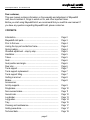
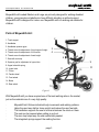
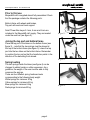
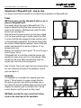
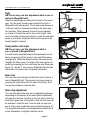
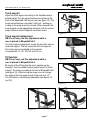
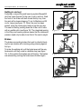
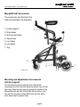
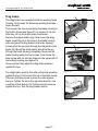
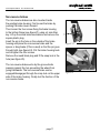
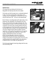
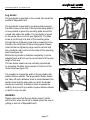
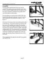
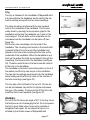
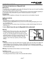
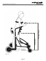
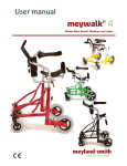
User manual
model medium and large
meyland-smith
mobility and more
www.meyland-smith.dk Tel: +45 98 96 19 85
Dear customer,
This user manual contains information on the assembly and adjustment of Meywalk®
mk3, how to maintain it, things to watch out for, and other important items.
Before you start using Meywalk® mk3, we recommend that you read this user manual. If
you have any questions regarding Meywalk® mk3, please contact us.
CONTENTS:
Introduction................................................................................
Meywalk® mk3 parts.................................................................
Prior to first use.........................................................................
Joining the top part and bottom frame.......................................
Spring loading...........................................................................
Standard adjustment – step by step..........................................
Handlebar..................................................................................
Tubes.........................................................................................
Seat...........................................................................................
Seat position and angle.............................................................
Rear stop...................................................................................
Trunk support............................................................................
Trunk support replacement........................................................
Trunk support tilting...................................................................
Getting in and out......................................................................
Brakes.......................................................................................
Accessories:
Anti-tip supports........................................................................
Dragbrakes................................................................................
Non-reverse brakes...................................................................
Swivel locks...............................................................................
Leg divider.................................................................................
Leg guides.................................................................................
Tray............................................................................................
Cleaning and maintenance........................................................
Safety precautions.....................................................................
Technical data...........................................................................
page 2
Page 2
Page 3
Page 4
Page 4
Page 4
Page 5
Page 5
Page 5
Page 6
Page 6
Page 6
Page 7
Page 7
Page 7
Page 8
Page 8
Page 9
Page 10
Page 11
Page 12
Page 13
Page 14
Page 15
Page 17
Page 17
Page 19
www.meyland-smith.dk Tel: +45 98 96 19 85
Meywalk® mk3 models Medium and Large are primarily designed for walking disabled
children, young people and adults who have difficulty standing up without support.
Meywalk® mk3 is designed for indoor use. Meywalk® mk3 is a walking aid suitable for
children.
Parts of Meywalk® mk3:
1
2
1: Trunk support
2: Handlebar
3: Handlebar spanner grips
3
4
4: Thumb screw for adjustment of trunk support height
5: Thumb screw for adjustment of tilt function
6: Thumb screw for adjustment of seat height
5
6
7: Seat with reat stop
7
8
9
8: Spanner grip for adjustment of upper tube
9: Upper tube with spring
10: Lower tube
11
11: Tilt bar
10
14
12: Fender wheel
13: Front wheel
14: Brake
12
15: Rear wheel
13
Figure 1
With Meywalk® mk3 you have acquired one of the best walking aids on the market,
just as the materials are of a very high quality.
∙
∙
∙
∙
∙
∙
Meywalk® mk3 follows individual body movements and walking patterns.
Helps the user keep his/her torso upright and makes the user feel safe.
The handlebar supports the user’s arms and reduces the strain on them.
The seat can be lowered when getting in and out.
The rear stop helps keep the user comfortably seated.
The integrated springs support the walking function.
page 3
15
www.meyland-smith.dk Tel: +45 98 96 19 85
Prior to first use
Meywalk® mk3 is supplied almost fully assembled. Check
that the package contains the following parts:
Bottom frame with wheels and brakes,
Top part with seat and trunk support.
Note! Three Allen keys of 4 mm, 5 mm and 6 mm are
included in the Meywalk® mk3 supply. They are located
under the seat bar (see figure 2).
Figure
Figur 2 2
Joining the top part and bottom frame
Place the top part in the tubes on the bottom frame (see
figure 3) – note that the two springs must be placed at
the top of the bottom frame (see figure 3). Lower the top
part into the two tubes on the bottom frame. Remember
to position the top part so that the handle bar points in the
direction of the swivelling front wheels.
Figure
Figur 3 3
Spring loading
The two springs inside the tubes (see figure 4) can be
changed to obtain harder or softer suspension. As a
guideline, the weight of the user must be able to fully
compress the springs.
There are four different spring hardness levels
corresponding to the following body weight:
White springs for minimum 20 kg
Yellow springs for minimum 45 kg
Blue springs for minimum 65 kg
Red springs for minimum 80 kg.
page 4
Figure
Figur 4 4
www.meyland-smith.dk Tel: +45 98 96 19 85
Adjustment of Meywalk® mk3 - step by step
It is always a good idea to consult our consultant before adjustment of Meywalk® mk3.
Tubes
NB! Do not carry out this adjustment while a user is
placed in Meywalk® mk3.
First roughly adjust the height of Meywalk® mk3. The
height is adjusted by lifting the lower spanner grip in the
green arrow’s direction. Simultaneously rotate the upper
spanner grip (see figure 5).
Note that when the upper spanner grip has been rotated
a bit, the lower spanner grip no longer needs to be lifted.
To ensure that the tube engages the lower spanner grips
is pressed slightly downwards. The tube will engage after
two rotations. Model Medium features 7 holes in total and
model Large features 8 at intervals of approx. 2.5 cm
between each hole.
Medium can be lifted a total of approx. 18 cm and Large a
total of approx. 20 cm.
If Meywalk® mk3 is to be lifted, rotate the spanner grip
towards the green arrow and if it is to be lowered, rotate
towards the red arrow. Make sure that both sides are
equally high; count the holes (see figure 6).
Rule of thumb: The correct height has been achieved when
the user’s elbows are abreast of the handlebar spanner
grips (see figure 7).
Figure
Figur 5 5
Figur 66
Figure
Handlebar
The handlebar is connected to two spanner grips (see
figure 7). When turned in the green arrow’s direction,
the spanner grips will open and the handlebar can rotate. When the desired handlebar angle has been found,
retighten the spanner grips by rotating them in the red
arrow’s direction until the points are fully closed.
NB! Make sure that the user cannot hurt his/her
head on the raised part of the handlebar.
page 5
Figure
Figur 77
www.meyland-smith.dk Tel: +45 98 96 19 85
Seat
NB! Do not carry out this adjustment while a user is
placed in Meywalk® mk3.
Adjust the seat height according to the length of the user’s
legs. Turn the lower thumb screw located at the front of
Meywalk® mk3 (see figure 8). The thumb screw features a
“child lock” which is released according to the press-andturn principle. When released, the seat can be adjusted
up or down. Position the seat at the correct height. Hold
your hand under the seat bar bottom to make the seat slide
easily up and down. Retighten the thumb screw when the
desired height is reached.
Figure
Figur 8 8
Seat position and angle
NB! Do not carry out this adjustment while a
user is placed in Meywalk® mk3.
The seat can be adjusted forwards and backwards on the
bar by loosening the Allen screw on the seat fitting below
(see figure 9). When the desired position has been found,
retighten the Allen screw. The angle of the seat can be adjusted by loosening the four nuts under the seat fitting (see
figure 10). Use an 11 mm spanner. Retighten the nuts after
adjustment. The seat is also completely removable.
Figure
Figur 9 9
Rear stop
The rear stop should always be tilted back when there is a
user in Meywalk® mk3. The rear stop can be put down by
pressing the small block until it is clear of the fitting. Then
the rear stop slides in under the seat.
Figur 1010
Figure
Rear stop adjustment
The rear stop behind the seat can be adjusted lengthways
depending on the position of the seat. Before adjustment,
put down the rear stop by lifting up the rear stop so that the
small block goes clear of its position. Now the rear stop can
be pushed in under the seat. From the end you can now
see an Allen screw inside the square profile (see figure 11).
The longitudinal direction can be adjusted by means of this
screw. Remember to retighten the Allen screw.
page 6
Figure
Figur 1111
www.meyland-smith.dk Tel: +45 98 96 19 85
Trunk support
Adjust the trunk support according to the individual user’s
optimal height. Turn the upper thumb screw located at the
front of the Meywalk® mk3 central tube (see figure 12). The
thumb screw features a so-called “child lock”, working according to the press-and-turn principle. When released, the
trunk support can be adjusted up and down until the correct
height has been found. Retighten the thumb screw.
Figure1212
Figur
Trunk support replacement
NB! Do not carry out this adjustment while a
user is placed in Meywalk® mk3.
For trunk support replacement, loosen the two Allen screws
under the support. The two screws fits all trunk supports.
The trunk support is available in five variants:
Circumference: 70, 90, 105,120 and 130 cm.
Tilt function
NB! Do not carry out this adjustment while a
user is placed in Meywalk® mk3.
By means of the tilt function the user’s posture can be
changed. Turn the middle thumb screw to the left to tilt the
support. The screw is located at the front of Meywalk® mk3
(see figure 14). While turning the screw, you can change
the angle of the trunk support and of the seat up to 14°.
The tilt function is continuously adjustable (see figures 15
and 16).
Figure1313
Figur
Figure 14
Figure
16
Figur 16
Figure
Figur 1515
page 7
www.meyland-smith.dk Tel: +45 98 96 19 85
Getting in and out
Featuring a unique lifting and lowering system Meywalk®
mk3 has made it easier for the user to get in and out. Grab
the front of the tilt bar with both hands and tip it up, then
the seat will be lowered approx.13 cm for Medium and 22
cm for Large (see figure 17). When the user has been
seated, close the trunk support and pull up the rear stop.
The seat is lifted by pushing down the tilt bar until it locks
with an audible click (see figure 18). The integrated gearing
in the lifting and lowering system means that the downward
pressure need only be about one third of the user’s weight.
Figure
Figur 1717
Brakes
The brakes are parking brakes that work by directly blocking the rear wheels with a braking pulley pressing against
the tyre.
To brake the walking aid, pull the brake levers all the way
backwards until they come to a definite stop (see figure
19). In this position the brakes are self-locking. The brakes
are released by pushing the brake levers forward again.
Figur 1818
Figure
Figur 1919
Figure
page 8
www.meyland-smith.dk Tel: +45 98 96 19 85
Meywalk® mk3 accessories
The accessories are attached to the
frame as indicated in the illustration:
1: Anti-tip supports
7
2: Drag brakes
3: Non-reverse brakes
4: Swivel locks
5: Leg divider
6: Leg guides
5
7: Tray
4
1
6
2 3
Figure 20
Mounting and adjustment of accessories
Anti-tip supports
Anti-tip supports are mounted on each side by first
removing one of the two bolts fixing the wheel. Use a 6 mm
Allen key. Place anti-tip supports against the outside of the
Meywalk® mk3 rear fork so that they fall into place in the
two rear fork recesses. Screw bolts back on from either
side. Remember to tighten firmly.
page 9
www.meyland-smith.dk Tel: +45 98 96 19 85
Drag brakes
The drag brakes are mounted inside the existing brake
housing. First loosen the brakes by pushing the brake
levers forward.
Then loosen the four screws fixing the brake housing to
the bottom frame (see figure 21) by means of a 4 mm
Allen key. Lift up the entire brake mechanism.
Remove the upper plastic plug. Now mount the drag
brake. Insert the pin in the hole on the brake housing
side and place the drag brake in the brake housing
ensuring that the pin goes through the drag brake (see
figure 22). Mount the small spacer and drive the pin
through the brake housing completely. Re-mount the
brake housing using the four screws. Then screw the
Allen screw with nut into the thread on the upper side of
the braking housing (see figure 23).
Screw and nut help adjust the drag brake pressure
against the tyre.
The drag brakes work by the roller at the back pressing
against the tyre. First loosen the nut on the Allen screw.
Then turn the Allen screw to press the roller against
the tyre. Tighten the nut in the opposite direction. Use
a method of trial and error to find the correct pressure
against the tyre. Test the drag brake function.
Figure 21
Figure 22
Figure 23
page 10
www.meyland-smith.dk Tel: +45 98 96 19 85
Non-reverse brakes
The non-reverse brakes are also mounted inside
the existing brake housing. First loosen the brake by
pushing the brake levers forward.
Then loosen the four screws fixing the brake housing
to the bottom frame (see figure 21) using a 4 mm Allen
key. Lift up the entire brake mechanism and remove the
square plastic plug.
Insert the pin in the hole on the outside of the brake
housing and place the non-reverse brake and the
spacer or drag brake (if this is used) so that the pin goes
through both (see figure 24). Put the brake housing back
and re-tighten the four screws.
Remove the round black plug and fit the snap lock in the
hole (see figure 25).
The non-reverse brake works by the grooved side
pressing against the tyre preventing the wheel from
going backwards. The non-reverse brake can be
engaged/disengaged through the snap lock on the upper
side of the brake housing. Finally test the function of the
non-reverse brake.
page 11
Figure2424
Figur
Figure 25
www.meyland-smith.dk Tel: +45 98 96 19 85
Swivel locks
The swivel locks are fastened to the frame of
Meywalk® mk3 directly behind the front wheels.
First make sure that the snap lock is completely fastened
to the nut on the mounting plate, if necessary use a
monkey wrench for tightening it. Pull back the top of the
snap lock and turn it 90° - the lock is now deactivated.
Each of the two mounting plates (with snap locks) is now
fastened to the underside of the triangular part of the
frame, which holds the front wheel (see figure 26). The
mounting plate is turned so that the nut faces down and
is placed so the hole in the mounting plate fits the hole
in the triangular part of the frame (the mounting plate for
the right-hand lock is inclined to the right when the snap
lock points straight forward and reversed for the lefthand lock). In this position the small knob on the upside
of the mounting plate can be fitted into a hole on the
triangle underneath the fender of the wheel.
When the mounting plate is placed correctly it is
fastened with the bolt from above, through first the
triangle and secondly the mounting plate. The hole in the
mounting plate has an inside thread so the bolt can be
screwed in with a 6 mm Allen key (see figure 27).
The front swivel wheel is locked by pulling back the snap
lock and turning it 90°.
page 12
Figure 26
Figure 27
www.meyland-smith.dk Tel: +45 98 96 19 85
Leg divider
The leg divider is mounted on the curved tube under the
saddle of Meywalk® mk3.
The leg divider is mounted by loosening and removing
the Allen screw on the side of the bent mounting plate. It
is now possible to place the mounting plate around the
curved tube under the saddle. The leg divider is turned
so the center tube is in front (see figure 28). The Allen
screw is put through one side of the mounting plate,
through the two tightening rings and is screwed into the
thread on the other side of the mounting plate. Please
note that the two tightening rings must be vertical and
the cylindrical rods must touch the sides of the mounting
plate (see figure 29).
Before the leg divider is fastened completely it can be
adjusted back and forth on the curved tube to fit the step
length of the user.
The two divider sheets can be vertically repositioned
by loosening the Allen screw placed on the front of the
center tube (see figure 30).
It is possible to change the width of the leg divider with
plastic distance sheets. The large plastic divider sheets
are taken off and a distance sheet is placed between the
divider sheet and the steel plate (on which the divider
sheets are mounted). A distance sheet increases the
width by 6 mm and it is possible to place distance sheets
on both or only one side.
WARNING:
Please make sure that the leg divider doesn’t collide
with the floor when the tilt bar is raised (when the user is
getting in and out of Meywalk® mk3).
page 13
Figure 28
Figure 29
Figure 30
www.meyland-smith.dk Tel: +45 98 96 19 85
Leg guides
The leg guides shield the feet of the user from the
wheels of the walking aid ensuring that the user’s foot
is not by accident caught under one of the wheels. With
the unique suspension brackets the leg guides will lift
over small objects and doorsteps.
The leg guides are mounted on the inside of the lower
frame by the brake unit (referred to as point 1) and the
tube holding the tilt bar (referred to as point 2) - see
figure 31.
First loosen the screws at the two mounting points with a
5 mm Allen key - at point 2 the extra key is used to stop
the screw on the outside from turning. The mounting
frame is turned so the highest vertical bar is in front and
the plates are positioned toward the middle of Meywalk®
mk3 (see figure 32). The screw at point 1 is replaced by
an M6x16 screw and at point 2 the threaded rod and flat
head bolt is replaced by the supplied ones, which are
longer. The mounting frame is fastened at each of the
two points.
point 1
Figure 31
Figure 32
This is repeated at the opposite side and the leg guides
are ready for use.
Figure 33
page 14
point 2
www.meyland-smith.dk Tel: +45 98 96 19 85
Tray
The tray is fastened to the handlebar of Meywalk® mk3.
It is placed below the handlebar and is held by the two
bent mountings along with the two tube mountings.
The tube mountings are fixed with the two supplied
bolts to the underside of the handlebar. This is most
easily done by opening the two spanner grips for the
handlebar and turning the handlebar so it rests on the
trunk support. The two bolts on the underside can be
unscrewed and the handlebar can be taken off (see
figure 35).
Pull the two tube mountings onto the ends of the
handlebar. The mountings are turned so the small catch
is placed furthest from the end of the handlebar and
placed so the hole in the mounting fits the hole on the
underside of the handlebar. When the handlebar is put
back on the walker the bolts are screwed in through the
mountings, the foam and into the handlebar (see figure
36). Therefore small holes in the foam must be made to
fit the hole in the handlebar.
The handlebar is turned to horisontal position (in front of
the walker) and the tray can be put on the handlebar.
The two bent mountings are pressed onto the handlebar
while making sure that the tray rests on the catches of
the tube mountings (see figure 37).
The tray has a thin foil fixed to the top of it. Photos etc.
can be put between tray and foil to inspire and amuse
the user of the walker. To place photos lift the foil in the
small flap that is bent upwards (see figure 37).
Tube mountings
Bent mountings
Figure 34
Figure 35
Figure 36
WARNING:
Do not lift the foil above an angle of 45° to the tray, since
that will pose a risk of damaging the foil. Do not squeeze
the foil in sharp folds since it may not be possible to
straighten them again. Do not place the tray so it is
strained by the thumb screws of Meywalk® mk3.
page 15
Figure 37
www.meyland-smith.dk Tel: +45 98 96 19 85
page 16
www.meyland-smith.dk Tel: +45 98 96 19 85
Cleaning and maintenance of Meywalk® mk3
Maintenance
The walking aid can be washed in warm water with detergent but take care not to wash the padding
on the trunk support, handle bar and rear stop.
With time the painted frame may take on a matt appearance if washed with detergent repeatedly. If
so, the frame can be polished with car polish. Follow the instructions on the polish.
Re-tightening
Regularly check the tightness of all grips, bolt, screws and nuts, and re-tighten if required.
Safety precautions
Warning:
• Meywalk® mk3 is a therapy product and should only be used as such!
• The spring system of Meywalk® mk3 may involve a risk of the walking aid toppling over if used
by a very restless user.
• Meywalk® mk3 rolls very easily and you should always consider potential dangers that the user
may roll over to.
Therefore: Never leave the user in Meywalk® mk3 unattended!
Warning:
• Always hold the tilt bar securely when a user is being lifted
or lowered. Especially when opening the tilt bar to lower
the user, you must be prepared for the upward force which
gradually increases as the tilt bar rises (see figure 38). Never
let go of the tilt bar in the middle of a lifting or lowering
operation, even if taken by surprise by the heavy weight
loading.
Big force
Little force
Figure 38
Warning:
• If fittings are removed, open tube ends may be revealed. These may have sharp inner edges and
may be dangerous for probing fingers. However, MEYWALK® mk3 is designed to avoid open
ends! If a situation with open tube ends should nevertheless arise, it is recommended that they be
closed off with plastic plugs.
Warning: Polyurethane and foam tubes are not to be consumed.
Limitations on use
• The maximum user weight permitted is 100 kg.
• The walking aid should only be used on flat, level and stable surfaces.
page 17
Figure 39
page 18
Trunk support height
Inner leg length
www.meyland-smith.dk Tel: +45 98 96 19 85
www.meyland-smith.dk Tel: +45 98 96 19 85
Technical data
Dimensions:
Length:
External width:
Internal width:
Seat height / inner leg length:
Trunk support height:
Trunk support options:
(chest circumference)
Medium:
85 cm
62 cm
47 cm
50 - 70 cm
90 - 115 cm
70 cm, 90 cm, 105 cm
120 cm, 130 cm
Large:
101 cm
69 cm
54 cm
70 - 95 cm
109 - 140 cm
70 cm, 90 cm, 105 cm
120 cm, 130 cm
30,5 kg
100 kg
33,5 kg
100 kg
Weight:
Meywalk® mk3, without accessories:
Max. load:
Materials:
Frame:
Fittings:
Padding:
Wheels:
Colour:
Powder-coated steel tubes
Matt-finish chromium plated steel
Polyurethane foam
Soft solid rubber tyres on plastic rims with service-free ball bearings
Red metallic or Blue metallic
CE markning
Meywalk® mk3 is CE marked. This guarantees that Meywalk® mk3
is in compliance with all relevant safety requirements specified in
Council Directive 93/42/EEC on medical devices.
Meywalk® mk3 is tested by Berlin Cert, Prüf- und Zertifizierstelle für
Medizinprodukte GmbH, an der Technischen Universität Berlin.
page 19
Dealer:
Manufacturer:
Meyland-Smith a/s
Industrivej 27, DK - 9830 Taars
Tel: +45 98 96 19 85
Fax: +45 98 96 19 86
[email protected]
www.meyland-smith.dk
Rev: MØC 300407