1
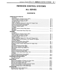
ViBE
1RU and 5RU platforms
1RU Chassis Front panel
User Manual
Release 4.2
46072085LB01
March 2011
ITALIANO
LEGGERE QUESTO AVVISO PER PRIMO!
Se non si capisce il contenuto del presente manuale
NON UTILIZZARE L’APPARECCHIATURA.
È anche disponibile la versione italiana di questo manuale, ma il costo è a carico dell’utente.
SVENSKA
LÄS DETTA FÖRST!
Om Ni inte förstår informationen i denna handbok
ARBETA DÅ INTE MED DENNA UTRUSTNING.
En översättning till detta språk av denna handbok kan också anskaffas, på Er bekostnad.
NEDERLANDS
LEES DIT EERST!
Als u de inhoud van deze handleiding niet begrijpt
STEL DEZE APPARATUUR DAN NIET IN WERKING.
U kunt tevens, op eigen kosten, een vertaling van deze handleiding krijgen.
PORTUGUÊS
LEIA O TEXTO ABAIXO ANTES DE MAIS NADA!
Se não compreende o texto deste manual
NÃO UTILIZE O EQUIPAMENTO.
O utilizador poderá também obter uma tradução do manual para o português à própria custa.
SUOMI
LUE ENNEN KÄYTTÖÄ!
Jos et ymmärrä käsikirjan sisältöä
ÄLÄ KÄYTÄ LAITETTA.
Käsikirja voidaan myös suomentaa asiakkaan kustannuksella.
FRANÇAIS
AVANT TOUT, LISEZ CE QUI SUIT!
Si vous ne comprenez pas les instructions contenues dans ce manuel
NE FAITES PAS FONCTIONNER CET APPAREIL.
En outre, nous pouvons vous proposer, à vos frais, une version française de ce manuel.
DANSK
LÆS DETTE FØRST!
Udstyret må ikke betjenes
MEDMINDRE DE TIL FULDE FORSTÅR INDHOLDET AF DENNE HÅNDBOG.
Vi kan også for Deres regning levere en dansk oversættelse af denne håndbog.
DEUTSCH
LESEN SIE ZUERST DIESEN HINWEIS!
Sollte Ihnen der Inhalf dieses Handbuches nicht klar verständlich sein, dann
BEDIENEN SIE DIESE GERÄTE NICHT!
Eine Übersetzung des Handbuches in diese Sprache ist gegen Berechnung lieferbar.
ESPAÑOL
LEA ESTE AVISO PRIMERO!
Si no entiende el contenido de este manual
NO OPERE ESTE EQUIPO.
Podemos asimismo suministrarle una traducción de este manual al (idioma) previo pago de una cantidad adicional que deberá abonar usted mismo.
Contacting Thomson Video Networks
Contacting Thomson Video Networks: http://www.thomson-networks.com/
Contacting Thomson Video Networks Support Centers
Contacting Thomson Video Networks Support Centers:
http://www.thomson-networks.com/about-us/contact-us/technical-support
Registered Trademarks and Licences
DOLBY
T A L
Dolby and the double-D symbol are registered trademarks
of Dolby laboratories.
Supply of this Implementation of Dolby technology does
not convey a license nor imply a right under any patent, or
any other industrial or intellectual property right of Dolby
Laboratories, to use this Implementation in any finished
end-user or ready-to-use final product. It is hereby notified
that a license for such use is required from Dolby Laboratories
MPEG-2 / MPEG-4 AAC audio encoding technology is
authorised
by
the
Fraunhofer
IIS
licence
(http://www.iis.fraunhofer.de/amm/)
As regards the broadcasting of televised programmes, MPEG-4 licences are unlike
MPEG-2 ones in that they are linked to services and not devices (Encoders and
Decoders). Content providers or operators are therefore requested to familiarize
themselves with the licensing conditions for MPEG4-AVC technology and to obtain
the rights from the relevant bodies before broadcasting programmes in MPEG-4.
Thomson Video Networks reserves the right to make changes at any
time without prior notice in order to improve design and supply the
best possible product.
We are taking great care of our publications. Please help us to improve
it by sending your feedback with the reference of the manual at the
email address:
[email protected]
BLANK PAGE
DOCUMENTATION ORGANISATION
vii
User documentation
DOCUMENTATION ORGANISATION AND MANUAL CONTENTS
XMS + MCC + ViBE documentation is contained on the CD-ROM shipped
together with the ViBE software CD-ROM.
A printed version of the ViBE 1RU Installation manual or ViBE 5RU Installation
manual is supplied with each ViBE chassis as these manuals contain essential safety
precautions which must be read before operating the device.
The rest of documentation is also available in printed version at an extra cost (see
section "Printed Manuals").
46072085LB01
March 2011
Thomson ViBE - Release 4.2
ViBE 1RU chassis F/P - User Manual
viii
DOCUMENTATION ORGANISATION
DOCUMENTATION CD-ROM
ViBE Documentation
(pdf files)
5RU ViBE
1RU ViBE
for ordering
for operation (reference manuals)
ViBE Configuration &
Redundancy Architectures Manual
• ViBE general overview
• Ordering references
• Redundancy architectures
ViBE 1RU Chassis Operation via the Front
Panel User Manual
• Management via the front panel LCD
ViBE Technical Specifications Manual
• Manager Function Specifications
• Encoder Function Specifications
• Decoder Function Specifications
• Front-End Function Specifications
for installation
ViBE 1RU Chassis Installation Manual
• General Safety Instructions
• Installing the chassis in a rack
• Chassis mechanical, electrical and
environmental specifications
ViBE 5RU Chassis Installation Manual
• General Safety Instructions
• Installing the chassis in a rack
• Chassis mechanical, electrical and
environmental specifications
for a quick start
Getting Started Manual
• Quick start
ViBE Operation via a Web Browser User
Manual
• Specifications
• Operation
ViBE MIB Programming Manual
• SNMP Interface & MIB Overview
• System Information, Alarms & Events
• Commands and Traps
(1)
for servicing
(2)
ViBE Servicing Manual
• Description of the local console
• Description of basic parameters
• Installing / Replacing a board
• Upgrading MPEG-2 encoder to MPEG-4
• Software options and Software downloading
• Downloading a Custom pattern
• Injecting IDs for BISS E scrambling
• Managing Web Interface Users
• Managing predefined configurations
• Managing community strings and SNMP info.
• Preventive maintenance
• Corrective maintenance
(1): A 1RU Chassis Installation manual (paper version) is supplied with each ViBE 1RU chassis.
(2): A 5RU Chassis Installation manual (paper version) is supplied with each ViBE 5RU chassis.
Alarm Documentation
Alarms & Events Manual
(pdf files)
CD-ROM Documentation
including ViBE and Alarm documentations
Thomson ViBE - Release 4.2
ViBE 1RU chassis F/P - User Manual
46072085LB01
March 2011
DOCUMENTATION ORGANISATION
ix
PRINTED MANUALS (OPTION)
As an option, the electronic manuals (PDF format) found on the Documentation
CD-ROM are also available in paper version.
ViBE User manuals
Sales references
N6000M0JAV
Optional
ENGLISH
Paper version
46072085LB01
March 2011
Manual type and comment
Manuals for ViBE, English paper version, including:
•
: 1 ViBE 1RU Chassis Installation manual;
•
: 1 ViBE 5RU Chassis Installation manual;
•
: 1 ViBE Configuration manual;
•
: 1 ViBE Technical Specification manual;
•
: 1 ViBE Getting started manual;
•
: 1 ViBE 1RU Operation from the front panel User manual;
•
: 1 ViBE Operation via a Web browser User manual;
•
: 1 ViBE MIB Programming manual;
•
: 1 ViBE Servicing manual.
•
: 1 Alarms & Events manual.
Thomson ViBE - Release 4.2
ViBE 1RU chassis F/P - User Manual
x
DOCUMENTATION ORGANISATION
BLANK PAGE
Thomson ViBE - Release 4.2
ViBE 1RU chassis F/P - User Manual
46072085LB01
March 2011
xi
PURPOSE OF THIS MANUAL
This manual describes operation via the 1RU chassis front panel. For more
information on device operation, please see the XMS 3500 User Manual if
operation is performed via the XMS 3500 Management system, or the Web
Interface User Manual if operation is performed via a Web Browser.
Notes:
• Chassis rack installation is described in the Chassis Installation guide.
• Chassis and board start-up is described in the Getting started guide.
• Advanced technical operations (installing a board, installing a software option,
etc.) are described in the Servicing manual.
46072085LB01
March 2011
Thomson ViBE - Release 4.2
ViBE 1RU chassis F/P - User Manual
xii
WHAT IS NEW IN RELEASE 4.2?
Release 4.2 features are identical to release 4.1 features.
Thomson ViBE - Release 4.2
ViBE 1RU chassis F/P - User Manual
46072085LB01
March 2011
1
CONTENTS
Contents
Contacting Thomson Video Networks ........................................................iii
Contacting Thomson Video Networks Support Centers ..........................iv
Registered Trademarks and Licences ..........................................................v
Purpose of this manual .................................................................................xi
What is new in release 4.2? .........................................................................xii
1 - Front panel description and overview................................................................ 3
1.1 - Foreword ........................................................................................................ 3
1.2 - Description and overview ............................................................................... 3
1.3 - Adjusting LCD screen contrast....................................................................... 5
2 - Screen description ............................................................................................... 6
2.1 - Screen menu tree........................................................................................... 6
2.2 - Summary of screen functions......................................................................... 7
2.3 - Device booting screen.................................................................................... 8
2.4 - Welcome screen............................................................................................. 8
2.5 - MAIN MENU screen ....................................................................................... 9
2.6 - ALARMS screen........................................................................................... 11
2.7 - BOARD screen............................................................................................. 12
2.7.1 - BOARD INFORMATION screen ....................................................... 13
2.8 - CHASSIS screen.......................................................................................... 15
2.8.1 - INFO screen (chassis) ...................................................................... 16
2.8.2 - IP SETTINGS screen ........................................................................ 17
2.8.2.1 - IP ADDRESS screen .......................................................... 18
2.8.2.2 - IP GATEWAY screen.......................................................... 19
2.8.2.3 - IP NETMASK screen .......................................................... 20
2.8.3 - RECALL screen (chassis)................................................................. 22
2.8.4 - REBOOT screen ............................................................................... 24
2.9 - [X - Y] function screen .................................................................................. 25
46072085LB01
March 2011
Thomson ViBE - Release 4.2
ViBE 1RU chassis F/P - User Manual
2
CONTENTS
2.9.1 - RECALL screen (function)................................................................. 26
2.9.2 - Predefined Encoder function configurations...................................... 27
3 - Appendix.............................................................................................................. 29
3.1 - Return your comments.................................................................................. 29
INDEX ................................................................................................31
Thomson ViBE - Release 4.2
ViBE 1RU chassis F/P - User Manual
46072085LB01
March 2011
1.1 - Foreword
3
1 - FRONT PANEL DESCRIPTION AND OVERVIEW
1.1 - Foreword
The aim of the front panel is not to replace the Management system but to provide a
basic control/command interface for the main settings.
Device operation via its front panel is limited to:
•
•
•
•
•
•
changing basic settings (IP settings, etc.);
displaying device codes and board and chassis serial numbers;
displaying installed functions and boards;
displaying the installed firmware;
displaying raised alarms;
recalling predefined function (partial configuration) or chassis (overall
configuration) configurations. These configurations can be defined via the Web
Interface or via the XMS 3500 and the Local Console. For more information, see
the Web Interface User Manual or the XMS 3500 User Manual and Servicing
guide.
• rebooting the device.
1.2 - Description and overview
The chassis front panel features an LCD screen, a 16-key keypad (0 to 9, ESC, OK
and 4 arrow keys), and a set of three LEDs providing a visual indication of overall
device operation.
POWER
UNIT FAIL
ESC
WARNING
1
3
5
7
9
2
4
6
8
0
OK
Figure 1: 1RU chassis front panel
46072085LB01
March 2011
Thomson ViBE - Release 4.2
ViBE 1RU chassis F/P - User Manual
4
1.2 - Description and overview
LEDs
The LEDs display the overall device state.
They indicate the following:
LED
Colour
Description
POWER
green
Device on
UNIT FAIL
red
At least one major alarm has been raised
WARNING
orange
At least one minor alarm has been raised
Table 1: Meaning of LEDs on 1RU chassis front panel
Keypad
The keypad features 16 keys:
• Six function keys used to display and select a menu or a setting.
Key
Functions
Move the cursor right.
Move the cursor left.
Move the cursor up.
Move the cursor down.
OK
Access the main menu, a sub-menu or confirm a setting
value.
ESC
Back to the menu above.
Table 2: Role of 1RU chassis front panel keys 1/2
• 10 numerical keys:
Keys
Functions
0 to 9
Edit setting values.
Table 3: Role of 1RU chassis front panel keys 2/2
Thomson ViBE - Release 4.2
ViBE 1RU chassis F/P - User Manual
46072085LB01
March 2011
1.3 - Adjusting LCD screen contrast
5
LCD
The LCD screen is an alphanumeric display featuring two lines each with forty
characters.
Symbols to guide operation, or markers, help to locate and/or select displayed
items:
Symbol
Indication
/
Wheeling symbol, in the top left of the welcome screen indicating that the
Manager board is operational.
>
<
Text preselection marker which can then be confirmed by pressing the
OK key on the keypad. Move using the four arrow keys.
<
Fixed marker to the right of the screen indicating that the list displayed
extends upwards.
>
Fixed marker to the right of the screen indicating that the list displayed
extends downwards.
Table 4: Meaning of 1RU chassis front panel LCD symbols
1.3 - Adjusting LCD screen contrast
For optimum readability of texts displayed on the LCD screen, it may be necessary
to adjust the contrast according to the lighting conditions:
- To increase screen contrast, press the ESC and
- To reduce screen contrast, press the ESC and
46072085LB01
March 2011
keys together.
keys together.
Thomson ViBE - Release 4.2
ViBE 1RU chassis F/P - User Manual
6
2.1 - Screen menu tree
2 - SCREEN DESCRIPTION
2.1 - Screen menu tree
BOOT MESSAGE
ViBE Launching
MAIN MENU
- Alarms
- Boards
WELCOME
SCREEN
- Chassis
- [FCT X-]
ALARMS
BOARDS
Boards
INFORMATION
CHASSIS
Chassis
INFORMATION
IP SETTINGS
IP address
IP address set
IP gateway
IP gateway set
IP netmask
IP netmask set
RECALL
REBOOT
[FCT X-Y]
RECALL
Figure 2: Menu tree of screens displayed on the 1RU chassis front panel
Thomson ViBE - Release 4.2
ViBE 1RU chassis F/P - User Manual
46072085LB01
March 2011
2.2 - Summary of screen functions
7
2.2 - Summary of screen functions
List summarising the functions which can be accessed via the screens:
Screens
Function
Function
description
Device booting screen
Indicates that the device is starting page 8
up.
Welcome screen
Indicates device name, IP
address and operation mode.
page 8
MAIN MENU screen
Displays available sub-menus and
functions installed in the chassis.
page 9
ALARMS screen
Displays alarms raised on the de- page 11
vice.
BOARD screen
Displays boards installed in the
chassis.
• BOARD INFORMATION screen
Displays board status according to page 9
the topology declared in the chassis
and board manufacturer
information.
CHASSIS screen
Displays available sub-menus.
page 15
• INFO screen (chassis)
Displays chassis manufacturer
information.
page 16
• IP SETTINGS screen
Displays device IP settings.
page 17
• IP ADDRESS screen
Used to edit device IP address.
page 18
• IP GATEWAY screen
Used to edit device IP gateway
address.
page 19
• IP NETMASK screen
Used to edit device IP netmask.
page 20
page 12
• RECALL screen (chassis)
Used to recall a predefined overall page 22
chassis configuration.
• REBOOT screen
Used to reboot all device boards.
page 24
[X - Y] function screen
Displays available sub-menu.
page 25
• RECALL screen (function)
Used to recall a predefined function page 26
configuration.
Table 5: Functions accessible via the 1RU chassis front panel screens
46072085LB01
March 2011
Thomson ViBE - Release 4.2
ViBE 1RU chassis F/P - User Manual
8
2.3 - Device booting screen
2.3 - Device booting screen
When the device is switched on, the firmware is loaded into the different device
modules. The following message is displayed while the Manager board is starting
up:
ViBE Launching
Figure 3: Booting screen - 1RU chassis LCD
Once the board is operational, the welcome screen is displayed:
/ DEVICE NAME
172.123.123.240
With
an
XMS 3500
Remotely Controlled
Figure 4: Welcome screen - 1RU chassis LCD
The welcome screen is described in section Welcome screen, page 8.
2.4 - Welcome screen
/ DEVICE NAME
XXX.XXX.XXX.XXX
Remotely Controlled
Figure 5: Welcome screen - 1RU chassis LCD
Meaning of fields:
/
Wheeling symbol indicating that the Manager board is
operational.
Thomson ViBE - Release 4.2
ViBE 1RU chassis F/P - User Manual
46072085LB01
March 2011
2.5 - MAIN MENU screen
9
DEVICE NAME
Chassis name (20 characters maximum). The name is
allocated by the Operator via the Management system.
XXX.XXX.XXX.XXX
Chassis IP address.
Remotely Controlled
Indicates that the device is being operated via an
XMS 3500 Management system (REMOTE mode). If
the device is being operated via the front panel or the
Web Interface, no message is displayed.
2.5 - MAIN MENU screen
To display the MAIN MENU screen:
• from the Welcome screen, press the OK key;
• from a sub-menu, press the ESC key once or more depending on the sub-menu
displayed.
46072085LB01
March 2011
Thomson ViBE - Release 4.2
ViBE 1RU chassis F/P - User Manual
10
2.5 - MAIN MENU screen
The following screen is displayed:
>Alarms<
Boards
Chassis
[FCT X]
[FCT X-Y]
[FCT X]
Figure 6: MAIN MENU screen - 1RU chassis LCD
To select a sub-menu, use the
or
keys and confirm with the OK key.
Available sub-menus:
Alarms
to display alarms raised on the chassis.
Boards
to get information about board reference numbers,
serial numbers and version numbers.
Chassis
to get information about the chassis reference number,
serial number and version number.
Sub-menus which can be accessed according to chassis boards:
The sub-menu headings [FCT X-Y] are made up of the type of function (FCT)
installed in the chassis followed by the chassis function board slot numbers X and Y.
The X value indicates the slot of the first function board and the Y value indicates
the slot of the last function board. If the function features only one board, only the Y
value will be displayed. The FCT function type has the following possible values:
FCT
Function type
MAN
Manager (not displayed in
the MAIN MENU screen)
ENC
Encoder
DEC
Decoder
PDH
PDH Front End
ASI
ASI Front End
HBT
IP Front End
Table 6: FCT and function type - 1RU chassis LCD
Thomson ViBE - Release 4.2
ViBE 1RU chassis F/P - User Manual
46072085LB01
March 2011
2.6 - ALARMS screen
11
Example
[ENC 2-4] indicates an Encoder function whose first board is in slot 2 and whose
last board is in slot 4.
The [FCT X-Y] sub-menus are used to recall a predefined configuration for the
function.
2.6 - ALARMS screen
The Alarms screen is used to view alarms raised on the chassis. To display this
screen, go to the MAIN MENU screen, select Alarms using the arrow keys and press
OK.
The following screen is displayed:
>Alarms<
Boards
Chassis
[FCT X]
[FCT X]
[FCT X-Y]
[FCT X]
[FCT X]
[FCT X-Y]
AID/AID_ext Critic
XX/YY
Alarm message
Figure 7: ALARMS screen - 1RU chassis LCD
Meaning of fields:
[FCT X-Y] :
indicates the function name. The syntax is described in
the previous section. [FCT X-Y] may display the value
CHASSIS if the alarm relates to the chassis.
AID/AID_ext :
indicates alarm identifiers (Alarme ID and Alarme ID
Extension) used to identify the alarm to make it easier
to find relevant information in the documentation.
46072085LB01
March 2011
Thomson ViBE - Release 4.2
ViBE 1RU chassis F/P - User Manual
12
2.7 - BOARD screen
Critic :
indicates alarm severity. The alarm can be MAJOR or
minor.
XX/YY :
XX indicates the number of the alarm in the YY list
where YY represents the total number of alarms raised.
Alarm message :
indicates the alarm description, which is identical to
the description displayed in the Management system.
The and keys are used to display the next or previous alarms. The
keys are used to scroll through the alarm text.
and
Note: The list of alarms is created when the ALARMS screen is selected. To update the
list of alarms, you will need to quit the ALARMS screen.
2.7 - BOARD screen
The BOARD screen is used to view the boards installed in the chassis. To display
this screen, go to the MAIN MENU screen, select Boards using the arrow keys and
press OK.
The following screen is displayed:
>[MANAGER]<
[ZZ ZZZ]
[
]
[XX XXXX]
[YYY YYY]
[
]
Figure 8: BOARD screen - 1RU chassis LCD
The different fields correspond to the boards detected in chassis slots 1 to 6 (rear
panel view).
Thomson ViBE - Release 4.2
ViBE 1RU chassis F/P - User Manual
46072085LB01
March 2011
2.7 - BOARD screen
13
Slot 1
Slot 4
Slot 5
Slot 2
Slot 3
Slot 6
Figure 9: 1RU chassis slots - rear view
To select a board, choose the required board using the arrow keys and confirm by
pressing the OK key.
2.7.1 - BOARD INFORMATION screen
The BOARD INFORMATION screen is used to get manufacturer information for
the boards installed in the chassis. To display this screen, go to the BOARD screen
(above), select the board using the arrow keys and press OK.
The beginning of the information list is displayed:
>Status
Active SW
: Comply with topology
: MANAGER XX.XX.XXX
Figure 10: BOARD INFORMATION screen 1/3 - 1RU chassis LCD
Press
to display the next part of the list:
>HW version
EQCODE
: N600HMANAA
: XXXX
Figure 11: BOARD INFORMATION screen 2/3 - 1RU chassis LCD
46072085LB01
March 2011
Thomson ViBE - Release 4.2
ViBE 1RU chassis F/P - User Manual
14
2.7 - BOARD screen
Press
to display the end of the list:
>EQCODE
S/N
: XXXX
: XXXXXXX
Figure 12: BOARD INFORMATION screen 3/3 - 1RU chassis LCD
Meaning of fields:
Status :
indicates whether the board installed in the slot corresponds to the board declared in the chassis topology.
Boards are declared via the XMS 3500 Management
system {Equipment Installation} application or the
Web Interface.
The following statuses may be displayed:
Comply with topology: the board installed corresponds
to the one declared (also indicates that no board has
been installed and none has been detected).
Board type mismatch: the board installed does not
correspond to the one declared.
Board missing: a board has been declared but there is
no board in the slot.
Board not declared: there is a board in the slot but it
has not been declared.
Active SW :
indicates the software release enabled on the board.
This information is available for the Manager board
and Main boards if their Status is Comply with topology.
HW version :
indicates the board version number. This information
is available for all boards.
EQCODE :
indicates the board code. The code is used to order a
software option for the board from Thomson. This
information is available for the Manager board and
Thomson ViBE - Release 4.2
ViBE 1RU chassis F/P - User Manual
46072085LB01
March 2011
2.8 - CHASSIS screen
15
Main boards. For further information about ordering
and installing software options, see the Servicing
manual.
S/N :
indicates the board serial number. This information is
available for all boards.
2.8 - CHASSIS screen
To display this screen, go to the MAIN MENU screen, select Chassis using the
arrow keys and press OK.
The following screen is displayed:
>Info<
IP settings
Recall
Reboot
Figure 13: BOARD screen - 1RU chassis LCD
Meaning of fields:
Info
used to display chassis information.
IP settings
used to configure the chassis IP settings.
Recall
used to recall a predefined chassis configuration.
These configurations can be defined via the Web Interface or via the XMS 3500 and the Local Console. For
more information, see the Web Interface User Manual
or the XMS 3500 User Manual and Servicing guide.
Reboot
used to reboot all chassis boards.
46072085LB01
March 2011
Thomson ViBE - Release 4.2
ViBE 1RU chassis F/P - User Manual
16
2.8 - CHASSIS screen
2.8.1 - INFO screen (chassis)
The INFO screen is used to get chassis manufacturer information. To display this
screen, go to the CHASSIS screen, select Info using the arrow keys and press OK.
The beginning of the information list is displayed:
>HW version
EQCODE
: N600CAC1AA 01
: XXXX
Figure 14: INFO screen 1/2 - 1RU chassis LCD
Press
to display the end of the list:
>EQCODE
S/N
: XXXX
: XXXXXXX
Figure 15: INFO screen 2/2 - 1RU chassis LCD
Meaning of fields:
HW version :
indicates the chassis version number.
EQCODE :
indicates the chassis code. This code is used to order a
software option for the chassis from Thomson.
S/N :
indicates the chassis serial number.
Thomson ViBE - Release 4.2
ViBE 1RU chassis F/P - User Manual
46072085LB01
March 2011
2.8 - CHASSIS screen
17
2.8.2 - IP SETTINGS screen
The IP SETTINGS screen is used to view the IP settings. To display this screen, go
to the CHASSIS screen, select the IP Settings sub-menu using the
ou
keys
and press OK.
The beginning of the IP settings list is displayed:
>IP Address
: 192.128.120.200
IP Gateway
: 192.008.001.002
Figure 16: IP SETTINGS screen 1/2 - 1RU chassis LCD
Press
to display the end of the list:
IP Gateway
: 192.008.001.002
>IP Netmask
: 255.255.255.000
Figure 17: IP SETTINGS screen 1/2 - 1RU chassis LCD
Meaning of fields:
IP Address :
indicates the current device IP address.
IP Gateway :
indicates the current IP Gateway address. If a
GATEWAY address is not used, the value must be set
to 000.000.000.000.
IP Netmask :
indicates the current IP Netmask address.
46072085LB01
March 2011
Thomson ViBE - Release 4.2
ViBE 1RU chassis F/P - User Manual
18
2.8 - CHASSIS screen
2.8.2.1 - IP ADDRESS screen
The IP ADDRESS screen is used to change the device IP address. To display this
screen, go to the IP SETTINGS screen, select the IP Address sub-menu using the
or keys and press OK.
The following screen is displayed:
IP Address
: 192.128.120.200
New value
: 192.128.120.155
Figure 18: IP ADDRESS screen 1/3 - 1RU chassis LCD
Meaning of fields:
IP Address :
indicates the current device IP address.
New value :
indicates the new IP address value.
Procedure for changing the IP address:
• Enter the new IP address value in the New value field using the 0 to 9 keys. You
can move quickly through the digits using the
or keys.
• Confirm the new value by pressing OK.
• If the entered value is correct, the following information screen is displayed:
Info : Use reboot to apply changes
Press OK or Esc to continue
Figure 19: IP ADDRESS screen 2/3 - 1RU chassis LCD
It prompts the user to reboot the device for the new values to be acknowledged.
Press OK or ESC to go back to the previous screen.
Thomson ViBE - Release 4.2
ViBE 1RU chassis F/P - User Manual
46072085LB01
March 2011
2.8 - CHASSIS screen
19
• If the entered value is incorrect, the following warning screen is displayed:
Error : Invalid IP Address
Press OK or Esc to continue
Figure 20: IP ADDRESS screen 3/3 - 1RU chassis LCD
It warns the user that the entered value contains an error. Press OK or ESC to go
back to the previous screen.
• Reboot the device. See section REBOOT screen, page 24.
2.8.2.2 - IP GATEWAY screen
To display the IP GATEWAY screen, go to the IP SETTINGS screen, select the IP
Gateway sub-menu using the or keys and press OK.
The following screen is displayed:
IP Gateway
: 192.128.120.200
New value
: 192.128.120.202
Figure 21: IP GATEWAY screen 1/3 - 1RU chassis LCD
Meaning of fields:
IP Gateway :
indicates the current device IP Gateway address.
New value :
indicates the new IP Gateway address value.
Procedure for changing the IP Gateway address:
• Enter the new IP Gateway address value in the New value field using the 0 to 9
keys. You can move quickly through the digits using the
or
keys.
46072085LB01
March 2011
Thomson ViBE - Release 4.2
ViBE 1RU chassis F/P - User Manual
20
2.8 - CHASSIS screen
• Confirm the new value by pressing OK.
• If the entered value is correct, the following information screen is displayed:
Info : Use reboot to apply changes
Press OK or Esc to continue
Figure 22: IP GATEWAY screen 2/3 - 1RU chassis LCD
It prompts the user to reboot the device for the new address values to be
acknowledged. Press OK or ESC to go back to the previous screen.
• If the entered value is incorrect, the following warning screen is displayed:
Error : Invalid IP Gateway
Press OK or Esc to continue
Figure 23: IP GATEWAY screen 3/3 - 1RU chassis LCD
It warns the user that the entered value contains an error. Press OK or ESC to go
back to the previous screen.
• Reboot the device. See section REBOOT screen, page 24.
2.8.2.3 - IP NETMASK screen
To display the IP NETMASK screen, go to the IP SETTINGS screen, select the IP
Netmask sub-menu using the or keys and press OK.
The following screen is displayed:
IP Netmask
: 255.255.255.000
New value
: 000.000.000.000
Figure 24: IP NETMASK screen 1/3 - 1RU chassis LCD
Thomson ViBE - Release 4.2
ViBE 1RU chassis F/P - User Manual
46072085LB01
March 2011
2.8 - CHASSIS screen
21
Meaning of fields:
IP Netmask :
indicates the current device IP Netmask address. If
Netmask is not used, the address must be set to
000.000.000.000
New value :
indicates the new IP Netmask address value.
Procedure for changing the IP Netmask address:
• Enter the new IP Netmask address value in the New value field using the 0 to 9
keys. You can move quickly through the digits using the
or keys.
• Confirm the new value by pressing OK.
• If the entered value is correct, the following information screen is displayed:
Info : Use reboot to apply changes
Press OK or Esc to continue
Figure 25: IP NETMASK screen 2/3 - 1RU chassis LCD
It prompts the user to reboot the device for the new address values to be
acknowledged. Press OK or ESC to go back to the previous screen.
• If the entered value is incorrect, the following warning screen is displayed:
Error : Invalid IP Gateway
Press OK or Esc to continue
Figure 26: IP NETMASK screen 3/3 - 1RU chassis LCD
It warns the user that the entered value contains an error. Press OK or ESC to go
back to the previous screen.
• Reboot the device. See section REBOOT screen, page 24.
46072085LB01
March 2011
Thomson ViBE - Release 4.2
ViBE 1RU chassis F/P - User Manual
22
2.8 - CHASSIS screen
2.8.3 - RECALL screen (chassis)
The RECALL screen is used to recall an overall configuration of the chassis. These
configurations can be defined via the Web Interface or via the XMS 3500 and the
Local Console. For more information, see the Web Interface User Manual or the
XMS 3500 User Manual and Servicing guide. To display the RECALL screen, go to
the CHASSIS screen, select Recall using the
or
keys and press OK.
The following screen will be displayed if configurations have been stored:
>Y : XXXX
Z : XXXXXXXXXX
Figure 27: RECALL screen with stored configurations - 1RU chassis LCD
Meaning of fields:
Y:
indicates the number of the overall configuration.
Note: function configurations (which are not overall
configurations) are not displayed.
XXXX :
indicates the name of configuration as defined on
creation.
If no configurations have been stored in the chassis, the following screen will be
displayed:
No stored configuration
Press OK or Esc to continue
Figure 28: RECALL screen without stored configuration - 1RU chassis LCD
Press OK or ESC to go back to the previous screen.
Thomson ViBE - Release 4.2
ViBE 1RU chassis F/P - User Manual
46072085LB01
March 2011
2.8 - CHASSIS screen
23
Procedure for recalling an overall configuration:
• Select the configuration in the RECALL screen using the
• Confirm the selection by pressing OK.
or
keys.
• The following screen is displayed:
Recall Global Conf = # X?
(ESC) = NO
(OK) = YES
Figure 29: RECALL screen - selecting and confirming the configuration - 1RU chassis
LCD
X indicates the number of the overall configuration.
• Press ESC to go back to the previous screen. Press OK to display the following
information screen:
Recall conf = # X in progress ...
Figure 30: RECALL screen - recalling a configuration in progress - 1RU chassis LCD
Recall Conf XX in progress indicates that the configuration is in the process of
being recalled.
• At the end of the operation:
- If the configuration has been successfully recalled, the following screen will be
displayed:
Done
Press OK or Esc to continue
Figure 31: RECALL screen - recall successful - 1RU chassis LCD
Press OK or ESC to go back to the previous screen.
46072085LB01
March 2011
Thomson ViBE - Release 4.2
ViBE 1RU chassis F/P - User Manual
24
2.8 - CHASSIS screen
- If the configuration has not been successfully recalled, the following screen
will be displayed:
YYY XXXX: ZZZZZZZZZZZZZZZZZ
Press OK or Esc to continue
Figure 32: RECALL screen - recall unsuccessful - 1RU chassis LCD
Meaning of fields:
YYY :
indicates Err or Warn.
XXXX :
indicates an error code.
ZZZZ :
indicates an error message.
2.8.4 - REBOOT screen
The Reboot screen is used to reboot all device boards. To display this screen, go to
the CHASSIS screen, select Reboot using the arrow keys and press OK.
The following screen is displayed:
Reboot device
(ESC) = NO
(OK) = YES
Figure 33: REBOOT screen 1/2 - 1RU chassis LCD
Thomson ViBE - Release 4.2
ViBE 1RU chassis F/P - User Manual
46072085LB01
March 2011
2.9 - [X - Y] function screen
25
Procedure for rebooting the device:
Press OK to reboot all the boards in the chassis. If you do not wish to reboot the
device, press ESC to quit this screen.
The following screen is displayed while the device reboots:
Reboot in progress...
Figure 34: REBOOT screen 2/2 - 1RU chassis LCD
It is then replaced by the welcome screen described on page 8.
2.9 - [X - Y] function screen
To display the [X - Y] function screen, go to the MAIN MENU screen, select the
function using the arrow keys and press OK.
The following screen is displayed:
>Recall<
Figure 35: {X - Y} function creen - 1RU chassis LCD
Le seul choix proposé dans cette version permet :
Recall
46072085LB01
March 2011
used to recall a predefined function configuration. The
configuration needs to be defined beforehand using the
Web Interface. To define a configuration, see the Web
Interface User Manual.
Thomson ViBE - Release 4.2
ViBE 1RU chassis F/P - User Manual
26
2.9 - [X - Y] function screen
2.9.1 - RECALL screen (function)
The RECALL screen is used to recall a function configuration. These configurations
are predefined via the Web Interface or via the XMS 3500 and the Local Console.
Three Encoder function configurations are predefined on chassis shipment, see the
section below. To define configurations, see the Web Interface User Manual or the
XMS 3500 User Manual and Servicing guide. To display the RECALL screen, press
OK.
The following screen will be displayed if configurations have been stored:
>Y : XXXX
Z : XXXXXXXXXX
Figure 36: RECALL screen with stored configurations - 1RU chassis LCD
Meaning of fields:
Y :
indicates the function configuration number.
Note: Overall (chassis) configurations are not displayed.
XXXX :
indicates the configuration name as defined on creation.
If no configurations have been stored, the following screen will be displayed:
No stored configuration
Press OK or Esc to continue
Figure 37: RECALL screen without stored configuration - 1RU chassis LCD
Press OK or ESC to go back to the previous screen.
Thomson ViBE - Release 4.2
ViBE 1RU chassis F/P - User Manual
46072085LB01
March 2011
2.9 - [X - Y] function screen
27
Procedure for recalling a function configuration:
The procedure is the same as the one used to recall an overall configuration. See
section RECALL screen (chassis), page 22.
2.9.2 - Predefined Encoder function configurations
Three Encoder configurations have been predefined in compliance with WBUISOG profiles. An Encoder featuring an SP ENC board can use one of the three
configurations. An Encoder featuring a DP ENC board can use the WBU-LBR
configuration.
XMS File Name WBU-LBR.mcf
Encoder
Service
WBU-HBR.mcf
WBU-MBR.mcf
Web Browser
File Name
WBU-LBR
WBU-HBR
WBU-MBR.mcf
Output Rate
8.448 Mb/s
21.502 Mb/s
11.666 Mb/s
Signaling Mode
DVB
DVB
DVB
Generate TSDT
Yes
Yes
Yes
Packet Size
188
188
188
Station Name
WBU-profile
WBU-profile
WBU-profile
TSDT
repetition rate
10 s
10 s
10 s
Service ID
256
256
256
PMT PID
128
128
128
PCR PID
256
256
256
Type
TV Service
TV Service
TV Service
Name
TV
TV
TV
Provider Name
None
None
None
Scrambling
No
No
No
Table 7 : Predefined configuration parameters
46072085LB01
March 2011
Thomson ViBE - Release 4.2
ViBE 1RU chassis F/P - User Manual
28
2.9 - [X - Y] function screen
Video
Audio 1 & 2
Profile
4:2:0 MP@ML
4:2:2@ML
4:2:2@ML
PID
256
256
256
Bitrate
7.3 Mb/s
19.8 Mb/s
9.0 Mb/s
Coding
Normal Delay
Normal Delay
Normal Delay
Source
SDI
SDI
SDI
Resolution
720x576
720x576
720x576
GOP
12
12
12
Aspect Ratio
4:3
4:3
4:3
Input
Digital
Digital
Digital
PID audio 1
4112
4112
4112
PID audio 2
4128
4128
4128
Bit Rate
256 kb/s
384 kb/s
384 kb/s
Mode
Stereo
Stereo
Stereo
Coding
MPEG-1 Layer 2 MPEG-1 Layer 2 MPEG-1 Layer 2
Table 7 : Predefined configuration parameters
Thomson ViBE - Release 4.2
ViBE 1RU chassis F/P - User Manual
46072085LB01
March 2011
3.1 - Return your comments
29
3 - APPENDIX
3.1 - Return your comments
All comments help us to improve our publications.
Do not hesitate to contact us:
Thomson Grass Valley
Integration and Networking Solutions
Département Marketing
Service Documentation
Rue du Clos-Courtel
35517 CESSON-SEVIGNE - FRANCE
Please give the manual reference.
Reader name:
Company:
Address:
Phone:
Fax:
E-mail:
46072085LB01
March 2011
Thomson ViBE - Release 4.2
ViBE 1RU chassis F/P - User Manual
30
3.1 - Return your comments
BLANK PAGE
Thomson ViBE - Release 4.2
ViBE 1RU chassis F/P - User Manual
46072085LB01
March 2011
Index
31
INDEX
A
E
Active SW (Front Panel).............................14
AID/AID_ext (Front Panel)........................11
Alarm message (Front Panel) ....................12
Alarms (Front Panel) .................................10
ALARMS screen (Front Panel) ................11
EQCODE (Front Panel). 14, (Front Panel)16
ESC (Front Panel) .......................................4
F
B
BOARD INFORMATION screen (Front Panel) ...........................................................13
Board missing (Front Panel)......................14
Board not declared (Front Panel) ..............14
BOARD screen (Front Panel) ...................12
Board type mismatch (Front Panel) ...........14
Boards (Front Panel)..................................10
C
Chassis (Front Panel) ................................10
CHASSIS screen (Front Panel) ................15
Comply with topology (Front Panel)..........14
Critic (Front Panel)....................................12
D
DEVICE NAME (Front Panel).....................9
Device, rebooting .....................................25
Dolby ..........................................................v
46072085LB01
March 2011
FCT X-Y (Front Panel)...............................11
Front panel, 1RU chassis ............................3
Function configuration (recall) .................27
Function screen (Front Panel) ..................25
H
HW version (Front Panel)14, (Front Panel)16
I
Info (Front Panel) ......................................15
INFO screen (Front Panel) .......................16
Invalid IP Address (Front Panel) ...............19
Invalid IP Gateway (Front Panel)..20, (Front
Panel) ......................................................21
IP Address (Front Panel) 17, (Front Panel)18
IP ADDRESS screen (Front Panel) ..........18
IP address, changing .................................18
IP Gateway (Front Panel)17, (Front Panel)19
IP Gateway address, changing ..................19
IP GATEWAY screen (Front Panel) ........19
IP Netmask (Front Panel)17, (Front Panel)21
IP Netmask address, changing ..................21
IP NETMASK screen (Front Panel) .........20
IP settings (Front Panel) ............................15
Thomson ViBE - Release 4.2
ViBE 1RU chassis F/P - User Manual
32
IP SETTINGS screen (Front Panel) ......... 17
Index
Recall (Front Panel) .................................. 15
RECALL screen (Front Panel) ........... 22, 26
Remotely Controlled (Front Panel) ............. 9
K
Keypad (Front Panel) ................................. 4
L
LCD (Front Panel) ..................................... 5
LCD, contrast (Front Panel) ....................... 5
LEDs (Front Panel) .................................... 4
M
S
S/N (Front Panel)............ 15, (Front Panel)16
Screen menu tree (Front Panel) .................. 6
Status (Front Panel)................................... 14
U
Update list of alarms (Front Panel) ........... 12
Use reboot to apply changes (Front Panel)18,
(Front Panel)................ 20, (Front Panel)21
MAIN MENU screen (Front Panel) ........... 9
V
N
ViBE Launching (Front Panel) .................... 8
New value (Front Panel) 18, (Front Panel)19,
(Front Panel)........................................... 21
W
O
OK (Front Panel) ........................................ 4
Overall configuration (recall) .................. 23
WBU-ISOG profiles, predefined configurations ....................................................... 27
Welcome screen (Front Panel) ................... 8
X
P
XX/YY (Front Panel) .................................. 12
Purpose of this manual .............................. xi
R
Reboot (Front Panel) ...... 15, (Front Panel)24
Reboot in progress (Front Panel) .............. 25
REBOOT screen (Front Panel) ................ 24
Thomson ViBE - Release 4.2
ViBE 1RU chassis F/P - User Manual
46072085LB01
March 2011