1
XMU 3600
eXtensible Management Unit
XMU
User Manual
Release 4.50
46072582FA01
2
ITALIANO
LEGGERE QUESTO AVVISO PER PRIMO!
Se non si capisce il contenuto del presente manuale
NON UTILIZZARE L’APPARECCHIATURA.
È anche disponibile la versione italiana di questo manuale, ma il costo è a carico dell’utente.
SVENSKA
LÄS DETTA FÖRST!
Om Ni inte förstår informationen i denna handbok
ARBETA DÅ INTE MED DENNA UTRUSTNING.
En översättning till detta språk av denna handbok kan också anskaffas, på Er bekostnad.
NEDERLANDS
LEES DIT EERST!
Als u de inhoud van deze handleiding niet begrijpt
STEL DEZE APPARATUUR DAN NIET IN WERKING.
U kunt tevens, op eigen kosten, een vertaling van deze handleiding krijgen.
PORTUGUÊS
LEIA O TEXTO ABAIXO ANTES DE MAIS NADA!
Se não compreende o texto deste manual
NÃO UTILIZE O EQUIPAMENTO.
O utilizador poderá também obter uma tradução do manual para o português à própria custa.
SUOMI
LUE ENNEN KÄYTTÖÄ!
Jos et ymmärrä käsikirjan sisältöä
ÄLÄ KÄYTÄ LAITETTA.
Käsikirja voidaan myös suomentaa asiakkaan kustannuksella.
FRANÇAIS
AVANT TOUT, LISEZ CE QUI SUIT!
Si vous ne comprenez pas les instructions contenues dans ce manuel
NE FAITES PAS FONCTIONNER CET APPAREIL.
En outre, nous pouvons vous proposer, à vos frais, une version française de ce manuel.
DANSK
LÆS DETTE FØRST!
Udstyret må ikke betjenes
MEDMINDRE DE TIL FULDE FORSTÅR INDHOLDET AF DENNE HÅNDBOG.
Vi kan også for Deres regning levere en dansk oversættelse af denne håndbog.
DEUTSCH
LESEN SIE ZUERST DIESEN HINWEIS!
Sollte Ihnen der Inhalf dieses Handbuches nicht klar verständlich sein, dann
BEDIENEN SIE DIESE GERÄTE NICHT!
Eine Übersetzung des Handbuches in diese Sprache ist gegen Berechnung lieferbar.
ESPAÑOL
LEA ESTE AVISO PRIMERO!
Si no entiende el contenido de este manual
NO OPERE ESTE EQUIPO.
Podemos asimismo suministrarle una traducción de este manual al (idioma) previo pago de una cantidad adicional que deberá abonar usted mismo.
XMU 3600, release 4.50
User Manual
46072582FA01
3
Contacting Thomson Video Networks
Contacting Thomson Video Networks: http://www.thomson-networks.com/
Thomson Video Networks reserves the right to make changes at any
time without prior notice in order to improve design and supply the
best possible product.
46072582FA01
XMU 3600, release 4.50
User Manual
4
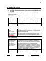
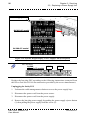
Manual Conventions
The following symbol conventions are used in this manual:
This symbol is intended to alert you to the presence of a potential for
property damage, personal injury or death.
This symbol identifies conditions or pratices that could result in
damage to this device or other property.
This symbol indicates supplemental information that helps you make
better use of the device.
This symbol indicates important information that helps you make
better use of the device.
This symbol indicates the following information will help you solve
a problem.
XMU 3600, release 4.50
User Manual
46072582FA01
5
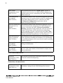
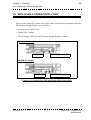
Set of XMS/XMU manuals
1. XMS/XMU documentation included in the XMS software and XMS/XMU
CD-ROM.
XMS/XMU documentation in pdf format is included within the XMS/XMU
software. It consists of:
XMS/XMU documentation
XMS/XMU
Specifications manual
(46073348CA)
This manual is a general presentation of the XMS
Management System and XMU Management Unit. It gives the
sizing, the ordering references and the list of the managed
devices with their releases. It summarizes the XMS user
application features.
XMS/XMU Alarms
manual (46072227LA)
This manual provides the list of alarms managed by
XMS/XMU Management System.
XMU documentation
XMU Installation
manual
(46073240AB)
This manual contains all the information required to set up the
XMU Management Unit. A printed copy is also provided with
the XMU Management Unit.
XMU User manual
(46072582FA)
This manual contains all the information required to use the
XMU Management Unit (including the Installation manual).
- this manual.
XMS documentation
XMS Server Platform
Installation manual
(46073347AB)
This manual explains how to set up and start up the XMS
server platform for proper operation in your Head-End. A
printed copy is also provided with each XMS server platform.
XMS Software
Installation manual
(46072194LD)
This manual provides the required conditions and the
operating procedure for upgrading the XMS Server software
onto the XMS Server platform and for installing or upgrading
the XMS client software. A printed copy is also provided with
each XMS software upgrade kit and with each XMS server
platform (for installing XMS client software).
XMS Software
Operation manual
(46072193PA)
This manual contains all the information required for the
Operator to use the applications of the XMS Management
System.
46072582FA01
XMU 3600, release 4.50
User Manual
6
XMS SNMP
Programming Guide
(46073519CA)
This document describes the {SNMP Agent} which is a
standard interface between an NMS (Network Management
System) and any device controlled by the XMS 3500 and the
XMS 3500 itself.
CAS Management
User Manual
(46073581BA)
This manual contains all the information required to provision
interfaces with CAS systems and set-up PayTV configurations
using XMS Management System. It describes the XMS
{Commercial Configuration} application and the
OpenCAS/OpenSCS gateway.
Telecom Transmission
Management User
Manual
(46073582BA)
This manual contains all the information required to set up
telecom transmissions managed by the XMS Management
System. It describes the XMS {Telecom Transmission
Desktop} application which enables the Telecom Operator to
monitor IP (and legacy ATM) transmissions and manage
profile and address books. It also describes the XMS {Web
Telecom Transmission} application which enables the user to
manage and monitor transmissions via a Web Browser.
Setup and download
tools User Manual
(46073583BA)
This manual describes different tools for performing the setup
of the equipment (including the IP address), for downloading
new product packages to one or more devices and for updating
options on devices.
Signaling Editor
User Manual
(46073584BA)
This manual describes the SigEditor user-friendly tool used for
editing all SI/PSI tables.
Time Management
User Manual
(46073585BA)
This manual contains all the information required for the
devices of the same domain (a Head-End for example) to be
time synchronized.
Flextream documentation
Flextream
Configuration Guide
(46073490CA)
This manual contains all the information required to set up the
Flextream statistical multiplexing.
Redundancy documentation
Redundancy
Configuration Guide
(46073491CA)
XMU 3600, release 4.50
User Manual
This manual contains all the information required to set up the
redundancy managed by the XMS Management System.
46072582FA01
7
2. Umbrella XMS documentation included in the Umbrella XMS CD-ROM.
XMS Umbrella
Specifications and
Operation manual
(46073417CA)
This manual contains all the information regarding the
Umbrella XMS feature.
3. High Availability XMS documentation included in the High Availability
XMS CD-ROM.
XMS High Availability
User Manual
(46073518AB)
46072582FA01
This manual aims to guide the customer to install, configure
and operate the XMS High Availability (HA). XMS High
Availability (HA) is based on Safekit Mirror architecture. It
provides a robust, efficient, and easy way to set-up 1+1 XMS
server redundancy.
XMU 3600, release 4.50
User Manual
8
Purpose of this manual
This manual contains all the information required to use the XMU Management
Unit (including the Installation manual).
It contains three chapters.
Chapter 1 - INSTALLATION and START-UP explains the
necessary on initial start up: equipment connection, power up, set-up.
operations
Chapter 2 - OPERATION describes how to save/recall a reference configuration
to/from a removable storage device (USB key).
Chapter 3 - SERVICING gives useful information about firmware, application
software upgrading and option management.
XMU SPECIFICATIONS are provided in the XMS/XMU Product
Specifications manual (ref. 46073348).
XMU REDUNDANCY is described in the XMS/XMU Redundancy
Configuration Guide (ref. 46073491).
XMU 3600, release 4.50
User Manual
46072582FA01
9
General Safety Instructions
Refer to the instructions given in the HPTM ProLiant DL360 Documentation
provided by the server manufacturer or retrieve this information from the HP web
site at the following url: http://www.hp.com
46072582FA01
XMU 3600, release 4.50
User Manual
10
BLANK PAGE
XMU 3600, release 4.50
User Manual
46072582FA01
11
Contents
Contacting Thomson Video Networks ...............................................................3
Manual Conventions .........................................................................................4
Set of XMS/XMU manuals ................................................................................5
Purpose of this manual .....................................................................................8
General Safety Instructions ...............................................................................9
CHAPTER 1
INSTALLATION AND
START-UP
1.1 - Installation procedure ..................................................................................... 17
1.2 - Rack mounting................................................................................................. 18
1.3 - Power up .......................................................................................................... 18
1.4 - Setting the initial parameters via the Command Line Interface.................. 19
1.4.1 - Accessing the Command Line Interface.................................................... 19
1.4.1.1 - Accessing the CLI via the Ethernet link ......................................... 20
1.4.1.2 - Accessing the CLI via the serial link .............................................. 22
1.4.1.3 - Accessing the CLI using a keyboard, monitor and mouse connected to
the XMU 3600 .................................................................................. 23
1.4.2 - Help ........................................................................................................... 24
1.4.3 - Setting initial parameters ........................................................................... 25
1.4.3.1 - Editing XMU 3600 IP parameters for Ethernet ports...................... 26
1.4.3.1.1 - Editing XMU 3600 IP parameters for Ethernet port 0 (NIC1) 27
1.4.3.1.2 - Editing XMU 3600 IP parameters for Ethernet port 1 (NIC2) 29
1.4.3.1.3 - Setting a static route ........................................................ 29
1.4.3.2 - Setting the system clock parameters ............................................. 30
1.4.3.2.1 - Setting the date and time ................................................. 30
1.4.3.2.2 - Editing NTP server IP parameters ................................... 31
1.4.3.3 - Declaring the serial device server (if any) ...................................... 33
46072582FA01
XMU 3600, release 4.50
User Manual
12
1.4.3.4 - Launching watchdog at XMU starting for XMU redundancy with mutual
health monitoring .............................................................................. 36
1.5 - Setting the Boot Standby parameter in the XMS {Technical Configuration} application .................................................................................................................... 38
1.6 - Connecting the cables..................................................................................... 40
1.6.1 - Wiring view.................................................................................................
1.6.1.1 - XMU - SANDAR routing switcher (9-pin)........................................
1.6.1.2 - XMU - SANDAR routing switcher (25-pin)......................................
1.6.1.3 - XMU - Grass Valley routing switcher via VM3000..........................
1.6.1.4 - XMU - LEITCH routing switcher .....................................................
1.6.1.5 - XMU - TRITON routing switcher.....................................................
1.6.1.6 - XMU - CX 2000 routing switcher ....................................................
1.6.1.7 - XMU - DBP 282M switch ................................................................
1.6.1.8 - XMU - BARCO and NEWTEC modulators .....................................
1.6.1.8.1 - XMU - BARCO modulator ................................................
1.6.1.8.2 - XMU - NEWTEC modulator..............................................
1.6.1.9 - XMU - DBD4431/4434 decoders ....................................................
1.6.1.9.1 - Point to point link ..............................................................
1.6.1.9.2 - Multipoint link....................................................................
1.6.1.10 - XMU - DBD4433/4436 decoders ..................................................
42
44
46
48
50
52
54
56
58
58
60
62
62
64
68
CHAPTER 2
OPERATION
2.1 - Removable storage device management
(USB key) .................................................................................................................. 73
2.1.1 - Storage on Hard drive and removable storage device...............................
2.1.2 - Removable storage device management ..................................................
2.1.3 - Use of removable storage device ..............................................................
2.1.3.1 - Conserving reference configurations on USB keys ........................
2.1.3.2 - To load a configuration onto another XMU 3600............................
73
73
74
74
75
CHAPTER 3
SERVICING
3.1 - Introduction ...................................................................................................... 79
3.2 - Accessing the Command Line Interface........................................................ 80
3.2.1 - Accessing the CLI via the Ethernet link ..................................................... 81
3.2.2 - Accessing the CLI via the serial link .......................................................... 82
XMU 3600, release 4.50
User Manual
46072582FA01
13
3.2.3 - Accessing the CLI using a keyboard, monitor and mouse connected to the
XMU 3600............................................................................................................. 83
3.3 - Downloading firmware and application software using the CLI ................. 84
3.3.1 - Displaying firmware or application software releases
(firm_view and appl_view) .................................................................................... 87
3.3.2 - Downloading procedure (app_view, firm_view, app_down, firm_down,
app_togg, firm_togg, update) ............................................................................... 88
3.3.3 - Procedure for returning to the previous firmware or
application software release ................................................................................. 93
3.4 - Replacing a RAID1 hard drive ........................................................................ 94
3.5 - Replacing a Power Supply Unit...................................................................... 95
3.6 - Other maintenance commands ...................................................................... 98
Return your comments ................................................................. 101
Index ................................................................................................ 103
46072582FA01
XMU 3600, release 4.50
User Manual
14
BLANK PAGE
XMU 3600, release 4.50
User Manual
46072582FA01
Chapter 1 - Installation and Start-up
15
Chapter 1
Installation and Start-up
1.1 - Installation procedure.......................................................................... 17
1.2 - Rack mounting ..................................................................................... 18
1.3 - Power up ............................................................................................... 18
1.4 - Setting the initial parameters via the Command Line Interface....... 19
1.4.1 - Accessing the Command Line Interface ......................................... 19
1.4.1.1 - Accessing the CLI via the Ethernet link ......................................... 20
1.4.1.2 - Accessing the CLI via the serial link .............................................. 22
1.4.1.3 - Accessing the CLI using a keyboard, monitor and mouse connected to
the XMU 3600........................................................................................ 23
1.4.2 - Help ................................................................................................ 24
1.4.3 - Setting initial parameters ................................................................ 25
1.4.3.1 - Editing XMU 3600 IP parameters for Ethernet ports...................... 26
1.4.3.1.1 - Editing XMU 3600 IP parameters for Ethernet port 0 (NIC1)........ 27
1.4.3.1.2 - Editing XMU 3600 IP parameters for Ethernet port 1 (NIC2)........ 29
1.4.3.1.3 - Setting a static route ..................................................................... 29
1.4.3.2 - Setting the system clock parameters ............................................. 30
1.4.3.2.1 - Setting the date and time .............................................................. 30
1.4.3.2.2 - Editing NTP server IP parameters ................................................ 31
1.4.3.3 - Declaring the serial device server (if any) ...................................... 33
1.4.3.4 - Launching watchdog at XMU starting for XMU redundancy with mutual
health monitoring ................................................................................... 36
1.5 - Setting the Boot Standby parameter in the XMS {Technical Configuration} application ....................................................................................... 38
1.6 - Connecting the cables ......................................................................... 40
1.6.1 - Wiring view ..................................................................................... 42
1.6.1.1 - XMU - SANDAR routing switcher (9-pin) .......................................
1.6.1.2 - XMU - SANDAR routing switcher (25-pin) .....................................
1.6.1.3 - XMU - Grass Valley routing switcher via VM3000 .........................
1.6.1.4 - XMU - LEITCH routing switcher .....................................................
1.6.1.5 - XMU - TRITON routing switcher ....................................................
46072582FA01
44
46
48
50
52
XMU 3600, release 4.50
User Manual
16
Chapter 1 - Installation and Start-up
1.6.1.6 - XMU - CX 2000 routing switcher .................................................... 54
1.6.1.7 - XMU - DBP 282M switch ................................................................ 56
1.6.1.8 - XMU - BARCO and NEWTEC modulators ..................................... 58
1.6.1.8.1 - XMU - BARCO modulator ............................................................. 58
1.6.1.8.2 - XMU - NEWTEC modulator........................................................... 60
1.6.1.9 - XMU - DBD4431/4434 decoders .................................................... 62
1.6.1.9.1 - Point to point link ........................................................................... 62
1.6.1.9.2 - Multipoint link................................................................................. 64
1.6.1.10 - XMU - DBD4433/4436 decoders .................................................. 68
XMU 3600, release 4.50
User Manual
46072582FA01
Chapter 1 - Installation and Start-up
1.1 - Installation procedure
17
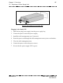
1.1 - INSTALLATION PROCEDURE
The following steps are required for device installation and initial configuration:
1. Mounting the device in a rack;
2. Powering the device;
3. Entering the initial parameters via the Command Line Interface:
-
setting the IP parameters,
adding a route,
setting the Date/Time,
setting the NTP configuration,
declaring the serial device server (if any);
4. Enabling an XMU expert parameter called Boot Standby when using a XMU
1+1 (or 1+2) redundancy scheme;
5. Rebooting the server.
6. Connecting the device to the other devices.
46072582FA01
XMU 3600, release 4.50
User Manual
18
Chapter 1 - Installation and Start-up
1.2 - Rack mounting
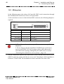
1.2 - RACK MOUNTING
Refer to the instructions given in the HPTM ProLiant DL360 Documentation
provided by the server manufacturer or retrieve this information from the HP web
site at the following url: http://www.hp.com
1.3 - POWER UP
Caution! Check that the XMU is not yet connected to the LAN as
factory-set IP addresses may cause disturbance on the LAN when the
XMU is switched on (address conflict).
Connect the power cord and switch on the device.
XMU 3600, release 4.50
User Manual
46072582FA01
Chapter 1 - Installation and Start-up
1.4 - Setting the initial parameters via the Command Line Interface
19
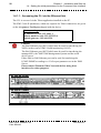
1.4 - SETTING THE INITIAL PARAMETERS VIA THE COMMAND
LINE INTERFACE
1.4.1 - Accessing the Command Line Interface
In this and the following sections, the Command Line Interface will be abbreviated
to CLI.
The CLI can be accessed in one of the following ways:
• via the Ethernet link and the PC Telnet application if the device IP address is
known;
• via the serial link and the PC hyperterminal application (or any terminal
emulator);
• or via a keyboard, monitor and mouse connected to the XMU 3600.
CLI use is the same regardless of the access mode used.
46072582FA01
XMU 3600, release 4.50
User Manual
20
Chapter 1 - Installation and Start-up
1.4 - Setting the initial parameters via the Command Line Interface
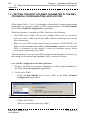
1.4.1.1 - Accessing the CLI via the Ethernet link
The CLI is accessed via the Telnet application installed on the PC.
The XMU 3600 IP parameters, which are required for Telnet connection, are given
on the Acceptance Test Report shipped with the device.
Factory settings:
IP address for eth1: 192.168.1.1
Subnet mask for eth1: 255.255.255.0
Default gateway: 192.168.1.254
Caution!
The Eth0 Ethernet port (NIC1 label) must be used for interfacing the
XMUs in the event of XMU Health monitoring (LAN2).
The Eth1 Ethernet port (NIC2 label) must be used for interfacing the
managed NEs, the XMS 3500 Management System and the serial
device server.
Either Eth0 or Eth1 Ethernet port can be used for interfacing the
ECMG/EMMG according to a CAS expert parameter set in the XMS
Server.
Please contact Thomson Video Networks before using these
interfaces for other purposes.
DL 360 G6 model
DL 360 G7 model
XMU 3600, release 4.50
User Manual
46072582FA01
Chapter 1 - Installation and Start-up
1.4 - Setting the initial parameters via the Command Line Interface
21
1. Set up the Telnet application as follows:
Terminal options
Emulation
No local echo, Block cursor, no CR LF
VT100 / ANSI
2. Set up the Telnet connection between the PC and the XMU 3600.
The welcome page displayed after connection will request the user login and
password. You must use admin and admin as login and password respectively.
Caution! The CLI is case sensitive (admin is correct, Admin is not
correct).
46072582FA01
XMU 3600, release 4.50
User Manual
22
Chapter 1 - Installation and Start-up
1.4 - Setting the initial parameters via the Command Line Interface
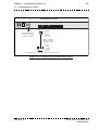
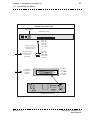
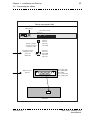
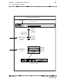
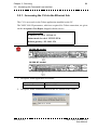
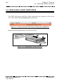
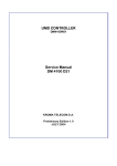
1.4.1.2 - Accessing the CLI via the serial link
The CLI is accessed via a RS232 serial link between the XMU 3600 and a terminal
or a PC emulating a terminal.
DL 360 G6 model
DL 360 G7 model
Serial port
Serial port
Figure 1.1: Serial port on the XMU rear panel
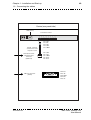
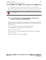
1. Set up the terminal port as follows: 9600 bauds, 8 bits, no parity, 1 start, 1 stop,
no flow control.
Figure 1.2: Terminal port setup for accessing the CLI
2. Click on OK to set up the connection between the PC and the XMU 3600.
The welcome page displayed after connection will request the user login and
password. You must use admin and admin as login and password respectively.
Caution! The CLI is case sensitive (admin is correct, Admin is not
correct).
XMU 3600, release 4.50
User Manual
46072582FA01
Chapter 1 - Installation and Start-up
1.4 - Setting the initial parameters via the Command Line Interface
23
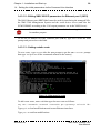
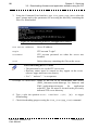
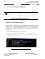
1.4.1.3 - Accessing the CLI using a keyboard, monitor and mouse
connected to the XMU 3600
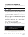
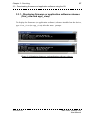
Following machine startup, BIOS startup messages and then Linux distribution
startup messages will be displayed, possibly followed by a few application software
startup messages.
After about 2 minutes, the screen will stop displaying messages.
Press the Return key. The following line will be displayed:
> <Hostname> Login:
Enter the login (admin) then press Return. The following line will be displayed:
> Password:
Enter the password (admin) then press Return.
46072582FA01
XMU 3600, release 4.50
User Manual
24
Chapter 1 - Installation and Start-up
1.4 - Setting the initial parameters via the Command Line Interface
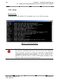
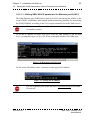
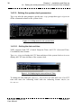
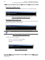
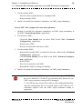
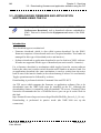
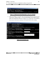
1.4.2 - Help
General help
To get the list of all available CLI commands, type help after the prompt.
Figure 1.3: General help menu
The CLI provides many commands. Some of these commands are
not, however, intended for the device user but reserved for Thomson
Video Networks use only. It is therefore important to only use the
commands described in this manual so as not to disrupt device
operation or jam the device, as this would require assistance from
Thomson Video Networks Customer Services.
XMU 3600, release 4.50
User Manual
46072582FA01
Chapter 1 - Installation and Start-up
1.4 - Setting the initial parameters via the Command Line Interface
25
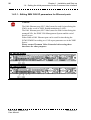
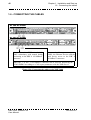
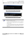
1.4.3 - Setting initial parameters
The following table lists the commands used to set the initial parameters.
User operation
Setting initial
parameters
Associated commands
Section
eth0/ipaddress, eth0/netmask,
eth0/gateway, eth1/ipaddress,
eth1/netmask, eth1/gateway
route/add
“Editing XMU 3600 IP parameters for
Ethernet ports”, page 26
ntp/utc-date & ntp/utc-sdate
ntp/cet-date & ntp/cet-sdate
“Setting the system clock parameters”,
page 30
ntp/ntp1
ntp/ntp2
“Editing NTP server IP parameters”,
page 31
serial/install_box
“Declaring the serial device server (if
any)”, page 33
watchdog/wd_startup
“Launching watchdog at XMU starting
for XMU redundancy with mutual
health monitoring”, page 36
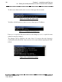
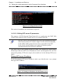
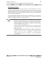
Each of these initial parameters can be set by the Operator. As indicated in the
Option menu, a change is enabled if the Operator quits the menu with the quit
command and disabled if the Operator quits the menu with the exit command.
Figure 1.4: Option menu
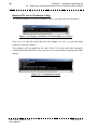
When quitting the Command Line Interface, the Operator will be asked to confirm
all changes performed during the session.
Figure 1.5: Confirmation request to confirm all changes
46072582FA01
XMU 3600, release 4.50
User Manual
26
Chapter 1 - Installation and Start-up
1.4 - Setting the initial parameters via the Command Line Interface
1.4.3.1 - Editing XMU 3600 IP parameters for Ethernet ports
Caution!
The Eth0 Ethernet port (NIC1 label) must be used for interfacing the
XMUs in the event of XMU Health monitoring (LAN2).
The Eth1 Ethernet port (NIC2 label) must be used for interfacing the
managed NEs, the XMS 3500 Management System and the serial
device server.
Either Eth0 or Eth1 Ethernet port can be used for interfacing the
ECMG/EMMG according to a CAS expert parameter set in the XMS
Server.
Please contact Thomson Video Networks before using these
interfaces for other purposes.
DL 360 G6 model
DL 360 G7 model
XMU 3600, release 4.50
User Manual
46072582FA01
Chapter 1 - Installation and Start-up
1.4 - Setting the initial parameters via the Command Line Interface
27
1.4.3.1.1 - Editing XMU 3600 IP parameters for Ethernet port 0 (NIC1)
The Eth0 Ethernet port (NIC1 label) must be used for interfacing the XMUs in the
event of XMU redundancy with mutual health monitoring (and also for interfacing
the ECMG/EMMG according to the CAS expert parameter set in the XMS Server.
Please contact Thomson Video Networks before using this interface
for another purpose.
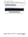
To set the IP address for Eth0, type Eth0 after the XMU prompt to get the XMU
eth0> prompt then type help to see all the commands related to the Eth0 port.
Figure 1.6: Help menu for Eth1 port
To edit a new IP address, enter ipaddress then type the IP address:
Figure 1.7: Setting the IP address
The two Ethernet ports (Eth0 and Eth1) must not belong to the same
IP network.
46072582FA01
XMU 3600, release 4.50
User Manual
28
Chapter 1 - Installation and Start-up
1.4 - Setting the initial parameters via the Command Line Interface
To edit a new subnet mask, enter netmask then type the new mask:
Figure 1.8: Setting the subnet mask
To define a default gateway, enter gateway then type its IP address:
Figure 1.9: Setting the default gateway
Enter quit to quit the Eth0 menu and save the changes (or exit to quit the menu
without saving the changes).
The changes will be applied at the end of the CLI session after the Operator’s
confirmation (this allows the Linux services to be rerun without requiring an XMU
reboot).
Figure 1.10: Confirmation request
XMU 3600, release 4.50
User Manual
46072582FA01
Chapter 1 - Installation and Start-up
1.4 - Setting the initial parameters via the Command Line Interface
29
1.4.3.1.2 - Editing XMU 3600 IP parameters for Ethernet port 1 (NIC2)
The Eth1 Ethernet port (NIC2 label) must be used for interfacing the managed NEs,
the XMS 3500 Management System and the serial device server (and also the
ECMG/EMMG according to the CAS expert parameter set in the XMS Server).
Please contact Thomson Video Networks before using this interface
for another purpose.
To set the IP address for Eth1 Ethernet port (NIC2), type Eth1 after the XMU
prompt and proceed as with Eth0.
1.4.3.1.3 - Setting a static route
To set a route , type route after the XMU prompt to get the XMU route> prompt
then type help to see all the commands related to the route(s).
Figure 11: Help menu for route
To add a new route, enter add then type the new route as follows:
any net <network> netmask <netmask> gw <gateway> eth<eth id>
Type quit to load modifications and restart Ethernet interfaces.
Type yes to confirm modifications.
46072582FA01
XMU 3600, release 4.50
User Manual
30
Chapter 1 - Installation and Start-up
1.4 - Setting the initial parameters via the Command Line Interface
1.4.3.2 - Setting the system clock parameters
Type ntp after the XMU prompt to get the XMU ntp> prompt then type help to see
all the commands related to the system clock.
Figure 1.12: Help menu for the system clock
1.4.3.2.1 - Setting the date and time
XMU supports both CET (Central European Time) and UTC (Universal Time,
Coordinated) time formats.
Type utc_date to display the UTC date and time of the system clock or date to
display the CET date and time of the system clock.
Figure 1.13: Displaying the current Date & Time
To change the date and time, type utc_sdate for UTC time and sdate for CET
time and enter the following fields with the following format: MM/DD/YY
hh:mm:ss.
XMU 3600, release 4.50
User Manual
46072582FA01
Chapter 1 - Installation and Start-up
1.4 - Setting the initial parameters via the Command Line Interface
31
Figure 1.14: Setting the Date & Time
The action is immediate (no confirmation required).
1.4.3.2.2 - Editing NTP server IP parameters
The purpose of NTP (Network Time Protocol) is to synchronize the XMU 3600
system clock with the clocks of other devices via a shared network.
The NTP service can synchronize two clocks provided that the initial
offset between these two clocks is slight. You are advised to manually
set the XMU 3600 system clock as close as possible to the NTP
server clock. Several minutes are required to achieve perfect
synchronization between the two platforms.
The XMU 3600 is set to operate as an NTP client. The external NTP server can be
backed-up so that two NTP server IP addresses can be set through the CLI: the first
one for the primary NTP server (ntp1), the second one for the backup NTP server
(ntp2).
Primary NTP server IP address
To edit the primary NTP server IP address, enter ntp1 after the XMU ntp> prompt
then type the IP address:
Figure 1.15: Setting an IP address for the primary server
46072582FA01
XMU 3600, release 4.50
User Manual
32
Chapter 1 - Installation and Start-up
1.4 - Setting the initial parameters via the Command Line Interface
Backup NTP server IP address (if any)
To edit the backup NTP server IP address, enter ntp2 then type the IP address:
Figure 1.16: Setting an IP address for the backup server (if any)
Enter quit to quit the menu and save the changes (or exit to quit the menu
without saving the changes).
The changes will be applied at the end of the CLI session after the Operator’s
confirmation (this allows the Linux services to be rerun without requiring an XMU
reboot).
Figure 1.17: Confirmation request
XMU 3600, release 4.50
User Manual
46072582FA01
Chapter 1 - Installation and Start-up
1.4 - Setting the initial parameters via the Command Line Interface
33
1.4.3.3 - Declaring the serial device server (if any)
Connect the serial device server to the XMU Eth1 port (NIC2) directly or via a
WAN.
The two Ethernet ports (Eth0 and Eth1) must not belong to the same
IP network.
Installation setup must be performed as described in the serial device server user
manual provided with the device. The IP address must be static (no DHCP use). It is
set and displayed on the MOXA server front panel.
Use the serial device server web interface to set up the appropriate type of serial link
interface. Select "RS485 - 4 Wire" among the three possible choices (RS485 2 Wire; RS485 - 4 Wire; RS 422). The selection can also be done via the LCD
interface.
Make sure that the serial device server is ON and that it is reachable on the network
from XMU (use the ping command as described in section “Enabling the ping
feature (ping)”, page 98).
For the XMU 3600, the number of managed serial ports is deduced from the
installed options. Note that for the whole system, the number of serial links is
currently limited to 8 links managed per unit.
In the CLI, type Serial to get the Serial> prompt.
Help related to the serial device server in the CLI (help)
Type help after the XMU serial> prompt to get the list of all available CLI
commands related to the serial device server.
Figure 1.18: Help related to the serial device server
46072582FA01
XMU 3600, release 4.50
User Manual
34
Chapter 1 - Installation and Start-up
1.4 - Setting the initial parameters via the Command Line Interface
Display boxes (display_boxes)
This command displays the IP list of the serial device servers already installed.
Figure 1.19: Displaying the serial device servers
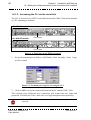
Declaring the boxes (Install_box)
This command is used to install a serial device server on the XMU 3600 and to
update the serial port list saved in the XMU.
You can install a server even if it is not connected to the XMU 3600.
Figure 1.20: Installing a serial device server
An XMU 3600 reboot is required.
- Type quit to get back to the XMU prompt.
- Type reboot after the XMU prompt.
- Confirm.
Figure 1.21: Rebooting the XMU
XMU 3600, release 4.50
User Manual
46072582FA01
Chapter 1 - Installation and Start-up
1.4 - Setting the initial parameters via the Command Line Interface
35
Uninstalling the boxes (Uninstall_box)
This command is used to uninstall a serial device server on the XMU 3600 and to
update the serial port list saved in the XMU.
Figure 1.22: Uninstalling a serial device server
This command has an immediate effect and does not require confirmation.
46072582FA01
XMU 3600, release 4.50
User Manual
36
Chapter 1 - Installation and Start-up
1.4 - Setting the initial parameters via the Command Line Interface
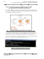
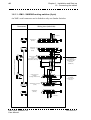
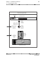
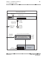
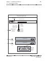
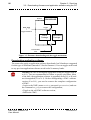
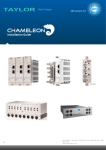
1.4.3.4 - Launching watchdog at XMU starting for XMU
redundancy with mutual health monitoring
In a XMU redundancy scheme with mutual health monitoring, all XMU must be
inter-connected through a dedicated LAN (LAN2 which uses the Eth0/NIC1 ports
of the XMUs) to monitor their "health".
Figure 1.23: Example of topology using 3 XMUs in a 1+2 redundancy scheme
A prerequisite to XMU redundancy is that all XMUs involved in the backed-up
group must have their watch-dog enabled through Telnet as described below.
Type watchdog after the XMU prompt to get the watchdog> prompt then type
wd_config to launch or not watchdog at XMU startup.
Figure 1.24: Launching watchdog at XMU startup
XMU 3600, release 4.50
User Manual
46072582FA01
Chapter 1 - Installation and Start-up
1.4 - Setting the initial parameters via the Command Line Interface
37
An XMU 3600 reboot is required.
- Type quit to get back to the XMU prompt.
- Type reboot after the XMU prompt.
- Confirm.
46072582FA01
XMU 3600, release 4.50
User Manual
38
Chapter 1 - Installation and Start-up
1.5 - Setting the Boot Standby parameter in the XMS {Technical Configuration}
application
1.5 - SETTING THE BOOT STANDBY PARAMETER IN THE XMS
{TECHNICAL CONFIGURATION} APPLICATION
When using a XMU 1+1 (or 1+2) redundancy scheme with or without mutual health
monitoring, it is required to enable an XMU expert parameter called Boot Standby
in the XMS {Technical Configuration} application.
When this parameter is enabled, the XMU behavior is the following:
• After XMU reboot, XMU will recover in standby mode (even if it was active
before the reboot). XMS will tell this XMU whether it should go active or not
after reconnection.
• When an active XMU is disconnected from the network (LINK DOWN), this
XMU becomes automatically standby (if Boot Standby is enabled). So when this
XMU is reconnected to the network, it does not configure devices before
receiving an explicit order from XMS.
This setting has to be present on all XMUs (nominal and redundant). In order to get
this setting on all (nominal and redundant) XMUs, proceed as follows:
Case of XMU configured in auto data replication:
1. Disable (if needed) the automatic redundancy on XMU group redundancy in
the XMS {Network Operation} application;
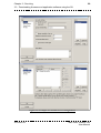
2. For the active XMU,
- Check the Boot Standby box on active XMU in the XMS {Technical
Configuration} application;
Figure 1.25: System parameters page in the XMS {Technical Configuration} application
- Reboot active XMU;
- Wait for reconnection with active XMU;
XMU 3600, release 4.50
User Manual
46072582FA01
Chapter 1 - Installation and Start-up
1.5 - Setting the Boot Standby parameter in the XMS {Technical Configuration}
39
3. For the standby XMU,
- Wait for end of synchronization on standby XMU;
- Reboot standby XMU;
4. Enable (if needed) the automatic redundancy on XMU group redundancy;
Case of XMU NOT configured in auto data replication:
1. Disable (if needed) the automatic redundancy on XMU group redundancy in
the XMS {Network Operation} application;
2. For the active XMU,
- Check the Boot Standby box on active XMU in the XMS {Technical
Configuration} application;
- Reboot active XMU;
- Wait for reconnection with active XMU;
3. For the standby XMU,
- Reinstall the standby XMU as nominal to become visible in the {Technical
Configuration} application.
- Check the Boot Standby box on XMU in the XMS {Technical Configuration} application;
- Reboot XMU;
- Wait for reconnection with XMU;
- Reinstall the XMU as backup (as initially);
4. Enable (if needed) the automatic redundancy on XMU group redundancy;
1. The former "save all" files made with Boot Standby = DISABLED
have to be deleted. If a "load all" is performed with a former file, the
XMU expert parameter setting will be damaged.
2. If a USB key have been used to make a cold configuration backup,
then the configuration has to be stored again in the USB key (i.e.
removable support) once the XMU expert parameter setting is
appropriate.
46072582FA01
XMU 3600, release 4.50
User Manual
40
Chapter 1 - Installation and Start-up
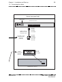
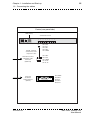
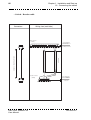
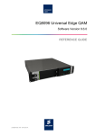
1.6 - Connecting the cables
1.6 - CONNECTING THE CABLES
DL 360 G6 model
DL 360 G7 model
Connect the other XMUs involved in
XMU redundancy with mutual health
monitoring to the NIC 1 10/100BaseT
connector.
Connect the Management system
(XMS), the Ethernet devices and the
serial device server to the NIC 2
10/100BaseT connector.
Either NIC 1 or NIC 2 10/100BaseT connector can be used for interfacing the
ECMG/EMMG according to a CAS expert parameter set in the XMS Server.
Figure 1.26: Connecting the cables to the XMU 3600
XMU 3600, release 4.50
User Manual
46072582FA01
Chapter 1 - Installation and Start-up
1.6 - Connecting the cables
41
BLANK PAGE
46072582FA01
XMU 3600, release 4.50
User Manual
42
Chapter 1 - Installation and Start-up
1.6 - Connecting the cables
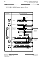
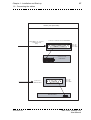
1.6.1 - Wiring view
In the following pages, the wiring of all possible XMU serial connections through
the N360HSL0AA serial device server are represented.
As the serial device server is fitted with an RJ45 connector, the following adaptor is
required:
RJ45 (Male)
SUBD15 (Female)
1
15
Pin 3 (Tx+)
<---------->
Pin 3 (Tx+)
Pin 4 (Tx-)
<---------->
Pin 11 (Tx-)
Pin 5 (Rx-)
<---------->
Pin 10 (Rx-)
Pin 6 (Rx+)
<---------->
Pin 2 (Rx+)
Pin 7 (GND)
<---------->
Pin 7 (GND)
1. The cable must be as short as possible to maintain acceptable line
adaptation.
2. Do not forget to declare/install the N360HSL0AA serial device
server via the XMU CLI before using a device (NE) that needs a
serial link in the topology managed by the XMS (refer to section
“Declaring the serial device server (if any)”, page 33).
All the connections between the serial device server and the serial devices use a
SubD15 connector on the serial device server end. Twisted pair cable impedance is
between 110 and 120Ω. The termination resistors must have the same value.
XMU 3600, release 4.50
User Manual
46072582FA01
Chapter 1 - Installation and Start-up
1.6 - Connecting the cables
43
Serial device server
Serial ports
1
I
O
1
2
8
1
3
8
1
4
8
1
5
8
1
6
8
1
7
8
1
8
8
1
8
LAN
AC POWER 100 - 240V, 47 - 63 Hz
RJ45
Pin 3: Tx+
Pin 4: TxPin 5: RxPin 6: Rx+
Pin 7: GND
to/from XMU 3600
(directly or via a hub
or switch or router)
RJ45M - SubD15F
Serial device server
adaptation cable
SUB-D15F
Pin 2: Rx+
Pin 3: Tx+
Pin 7: GND
Pin 10: RxPin 11: Tx-
to/from adaptation cables using a SUB-D15 male connector
Figure 1.27: Connections to the serial device server
46072582FA01
XMU 3600, release 4.50
User Manual
44
Chapter 1 - Installation and Start-up
1.6 - Connecting the cables
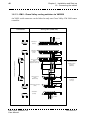
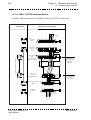
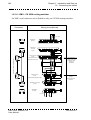
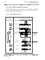
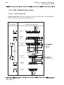
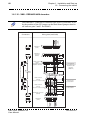
1.6.1.1 - XMU - SANDAR routing switcher (9-pin)
An XMU serial connector can be linked to only one Sandar Switcher.
Connectors
Wiring view (weld side)
110 ohms
2x
110 ohms
Termination
(female)
8
SUB-D15M
Termination
connector
(male)
8
14
15
7
15
13
6
7
12
5
6
14
5
13
11
4
12
10
3
4
9
P
2
3
11
1
2
9
10
SUB-D15M
P
Twisted pairs
SUB-D9F
cable length depending on installation
3
2
1
8
7
Cable connector
5
4
6
15 14 13 12 11 10
9
(male)
(serial device server
adaptation cable end)
P
Cable connector
(female)
(routing switcher end)
SUB-D9M
110 ohms
x2
Termination connector
(male)
Termination
(female)
8
9
5
4
5
4
9
1
6
7
3
1
2
7
8
4
6
2
3
8
9
5
7
3
6
2
1
P
to be plugged
to serial device server
adaptation cable
connector
(SubD 15F)
to be plugged
to SANDAR
routing switcher
connector
P
P
110 ohms
XMU 3600, release 4.50
User Manual
46072582FA01
Chapter 1 - Installation and Start-up
1.6 - Connecting the cables
45
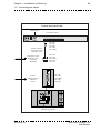
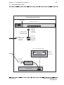
Device (rear panel side)
XMU (”NIC2”)
Serial device Server
Serial ports
1
I
O
1
2
8
1
3
8
1
4
8
1
5
8
1
6
1
8
7
8
1
8
8
1
8
LAN
AC POWER 100 - 240V, 47 - 63 Hz
Pin 3: Tx+
Pin 4: TxPin 5: RxPin 6: Rx+
Pin 7: GND
RJ45
RJ45M - SubD15F
Serial device server
adaptation cable
Serial device server
adaptation cable
connector
(SubD 15F)
Pin 2: Rx+
Pin 3: Tx+
Pin 7: GND
Pin 10: RxPin 11: Tx-
SUB-D15F
5
4
3
9
8
7
SANDAR
routing switcher
connector
(male)
2
1
6
Pin 2: Ra
Pin 3: Tb
Pin 5: GND
Pin 7: Rb
Pin 8: Ta
SANDAR Routing Switcher
46072582FA01
XMU 3600, release 4.50
User Manual
46
Chapter 1 - Installation and Start-up
1.6 - Connecting the cables
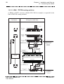
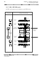
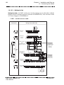
1.6.1.2 - XMU - SANDAR routing switcher (25-pin)
Connectors
Wiring view (weld side)
110 ohms
2x
110 ohms
SUB-D15M
Termination
(female)
8
Termination connector
(male)
8
14
15
7
15
SUB-D15M
SUB-D25M
cable length depending on installation
Cable connector
(male)
(serial device server
adaptation cable end)
6
8
7
15
5
6
14
4
5
13
6
14
11
12
13
7
5
13
11
4
12
9
2
3
4
12
10
3
2
3
1
P
9
10
11
P
1
1
2
10
P
9
Cable
13 12 11 10
8
7
5
4
3
2
6
9
connector
25 24 23 22 21 20 19 18 17 16 15 14
(male)
(routing switcher
end)
SUB-D25M
Termination
connector
(male)
1 10 ohms
x2
12
13
25
9
10
11
24
23
22
8
21
6
7
20
19
5
18
4
17
3
16
P
to be plugged
to SANDAR
routing switcher
connector
1
2
15
to be plugged
to serial device server
adaptation cable
connector
(SubD 15F)
14
Termination
25 24 23 22 21 20 19 18 17 16 15 14
(female)
9
44 3
13 12 11 10
1
8
7
5
2
6
P
P
110 ohms
XMU 3600, release 4.50
User Manual
46072582FA01
Chapter 1 - Installation and Start-up
1.6 - Connecting the cables
47
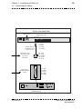
Device (rear panel side)
XMU (”NIC2”)
Serial device Server
Serial ports
1
I
O
1
2
8
1
3
8
1
4
8
1
5
8
1
6
8
1
7
8
1
8
8
1
8
LAN
AC POWER 100 - 240V, 47 - 63 Hz
RJ45
RJ45M - SubD15F
Serial device server
adaptation cable
Serial device server
adaptation cable
connector
(SubD 15F)
SANDAR
routing switcher
connector
(female)
SUB-D15F
Pin 3: Tx+
Pin 4: TxPin 5: RxPin 6: Rx+
Pin 7: GND
Pin 2: Rx+
Pin 3: Tx+
Pin 7: GND
Pin 10: RxPin 11: Tx-
1
14
Pin 14: Tb
Pin 2: Ta
Pin 7: GND
Pin 3: Ra
Pin 16: Rb
SANDAR Routing Switcher
46072582FA01
XMU 3600, release 4.50
User Manual
48
Chapter 1 - Installation and Start-up
1.6 - Connecting the cables
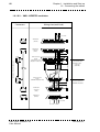
1.6.1.3 - XMU - Grass Valley routing switcher via VM3000
An XMU serial connector can be linked to only one Grass Valley VM 3000 router
controller.
Wiring view (weld side)
Connectors
110 ohms
2x
110 ohms
SUB-D15M
Termination
(female)
Termination
connector
(male)
14
15
8
7
8
7
15
12
13
6
5
6
14
5
13
11
4
9
2
3
4
12
10
3
1
2
11
1
9
10
SUB-D15M
SUB-D9M
110 ohms
x2
Termination connector
(male)
Termination
(female)
5
5
8
4
9
3
6
6
2
to be plugged
to serial device server
adaptation cable
connector
(SubD 15F)
P
to be plugged
to VM3000
connector
1
2
7
3
P
6
7
8
4
1
2
7
8
9
5
3
4
9
P
Twisted pairs
SUB-D9M
cable length depending on installation
1
8
7
6
5
4
3
2
Cable connector
15 14 13 12 11 10
9
(male)
(serial device server
adaptation cable end)
Cable connector
(male)
(VM3000 end)
P
1
P
P
110 ohms
XMU 3600, release 4.50
User Manual
46072582FA01
Chapter 1 - Installation and Start-up
1.6 - Connecting the cables
49
Device (rear panel side)
XMU (”NIC2”)
Serial device Server
Serial ports
1
I
O
1
2
8
1
3
8
1
4
8
1
5
8
1
6
8
1
7
1
8
8
8
1
8
LAN
AC POWER 100 - 240V, 47 - 63 Hz
RJ45
RJ45M - SubD15F
Serial device server
adaptation cable
Serial device server
adaptation cable
connector
(SubD 15F)
VM 3000 connector
(female)
46072582FA01
SUB-D15F
Pin 3: Tx+
Pin 4: TxPin 5: RxPin 6: Rx+
Pin 7: GND
Pin 2: Rx+
Pin 3: Tx+
Pin 7: GND
Pin 10: RxPin 11: Tx-
5
4
9
3
8
1
2
7
6
Pin 2: Ra
Pin 3: Tb
Pin 5: GND
Pin 7: Rb
Pin 8: Ta
XMU 3600, release 4.50
User Manual
50
Chapter 1 - Installation and Start-up
1.6 - Connecting the cables
1.6.1.4 - XMU - LEITCH routing switcher
An XMU serial connector can be linked to only one LEITCH router unit.
Wiring view (weld side)
Connectors
110 ohms
Termination
(female)
2x
110 ohms
Termination
connector
(male)
14
15
7
8
8
7
15
13
6
6
14
12
5
5
13
11
4
4
12
10
3
3
11
9
2
1
P
1
2
9
10
SUB-D15M
P
Twisted pairs
SUB-D9F
cable length depending on installation
Cable connector
8
7
3
2
1
6
5
4
(male)
9
15 14 13 12 11 10
(serial device server
adaptation cable end)
Cable connector
(female)
(Routing switcher end)
SUB-D9M
110 ohms
x2
Termination connector
(male)
Termination
(female)
8
9
5
4
5
4
9
1
6
7
3
1
2
7
8
4
6
2
3
8
9
5
7
3
6
2
1
to be plugged
to serial device server
adaptation cable
connector
(SubD 15F)
P
to be plugged
to remote connector
of LEITCH
routing switcher
P
P
110 ohms
XMU 3600, release 4.50
User Manual
46072582FA01
Chapter 1 - Installation and Start-up
1.6 - Connecting the cables
51
Device (rear panel side)
XMU (”NIC2”)
Serial device Server
Serial ports
1
I
O
1
2
8
1
3
1
8
4
8
1
5
8
1
6
8
1
7
8
1
8
8
1
8
LAN
AC POWER 100 - 240V, 47 - 63 Hz
Pin 3: Tx+
Pin 4: TxPin 5: RxPin 6: Rx+
Pin 7: GND
RJ45
RJ45M - SubD15F
Serial device server
adaptation cable
Serial device server
adaptation cable
connector
(SubD 15F)
Pin 2: Rx+
Pin 3: Tx+
Pin 7: GND
Pin 10: RxPin 11: Tx-
SUB-D15F
1
6
2
LEITCH
Routing switcher
connector
(male)
7
3
8
9
4
5
Pin 2: Ta
Pin 3: Rb
Pin 5: GND
Pin 7: Tb
Pin 8: Ra
LEITCH Routing Switcher
46072582FA01
XMU 3600, release 4.50
User Manual
52
Chapter 1 - Installation and Start-up
1.6 - Connecting the cables
1.6.1.5 - XMU - TRITON routing switcher
A RS485 to RS232 converter (Model 422LCOR for example) is required for the
link to TRITON routing switcher.
Connectors
Wiring view (weld side)
110 ohms
2x
110 ohms
Termination
(female)
SUB-D15M
Termination
connector
(male)
14
15
8
8
7
15
SUB-D15M
Cable connector
(male)
(serial device server
adaptation cable end)
8
13
6
7
7
15
13
13
10
3
4
12
5
6
14
11
4
5
6
14
12
5
3
11
11
P
1
2
P
9
10
3
4
12
9
2
2
10
1
P
9
to be plugged
to serial device server
adaptation cable
connector
(SubD 15F)
Twisted pairs
cable length depending on installation
Cable connector
(female)
(RS Converter RS422 end)
12
13
25
9
10
11
24
23
22
8
21
RS422 / RS232
CONVERTER
6
7
19
20
5
18
4
17
3
1
2
15
16
14
RS422 end
RS422/RS232 Converter (422LCOR Model)
RS232 end
12
13
25
9
10
11
24
23
22
8
21
6
7
20
19
5
18
4
17
3
16
1
2
15
P
14
Cable connector
(male)
(RS Converter RS232 end)
SUB-D9M
Cable connector
5
4
3
1
2
(male)
9
8
7
6
(TRITON Routing switcher end)
XMU 3600, release 4.50
User Manual
P
to be plugged
to TRITON
routing switcher
connector
46072582FA01
Chapter 1 - Installation and Start-up
1.6 - Connecting the cables
53
Device (rear panel side)
XMU (”NIC2”)
Serial device Server
Serial ports
1
I
O
1
2
8
1
3
1
8
4
8
1
5
8
1
6
8
1
7
8
1
8
8
1
8
LAN
AC POWER 100 - 240V, 47 - 63 Hz
Pin 3: Tx+
Pin 4: TxPin 5: RxPin 6: Rx+
Pin 7: GND
RJ45
RJ45M - SubD15F
Serial device server
adaptation cable
Serial device server
adaptation cable
connector
(SubD 15F)
TRITON
Routing Switcher
connector
(female)
Pin 2: Rx+
Pin 3: Tx+
Pin 7: GND
Pin 10: RxPin 11: Tx-
SUB-D15F
4
5
9
2
3
8
7
1
6
Pin 2: Tx
Pin 3: Rx
Pin 5: GND
TRITON Routing Switcher
46072582FA01
XMU 3600, release 4.50
User Manual
54
Chapter 1 - Installation and Start-up
1.6 - Connecting the cables
1.6.1.6 - XMU - CX 2000 routing switcher
An XMU serial connector can be linked to only one CX2000 routing switcher.
Wiring view (weld side)
Connectors
110 ohms
Termination
(female)
2x
110 ohms
Termination
connector
(male)
SUB-D15M
14
15
8
7
8
7
15
12
13
6
5
6
5
14
11
4
12
9
2
3
4
13
10
3
1
2
11
1
P
9
10
P
10 cm
SUB-D15M
8
7
15
5
6
14
13
4
12
3
1
2
11
10
9
P
Twisted pairs
cable length depending on installation
Cable connector
(male)
(serial device server
adaptation cable end)
SUB-D9M
10 cm
Cable connector
(male)
(CX2000 Routing Switcher end)
5
Termination connector
(male)
5
SUB-D9M
110 ohms
x2
4
9
5
110 ohms
XMU 3600, release 4.50
User Manual
8
3
to be plugged to
CX2000
Routing Switcher
connector
1
2
6
7
3
P
6
7
8
4
1
2
7
8
9
Termination
(female)
3
4
9
6
2
to be plugged
to serial device server
adaptation cable
connector
(SubD 15F)
1
P
P
110 ohms
46072582FA01
Chapter 1 - Installation and Start-up
1.6 - Connecting the cables
55
Device (rear panel side)
XMU (”NIC2”)
Serial device Server
Serial ports
1
I
O
1
2
8
1
3
8
1
4
8
1
5
1
8
6
8
1
7
8
1
8
8
1
8
LAN
AC POWER 100 - 240V, 47 - 63 Hz
Pin 3: Tx+
Pin 4: TxPin 5: RxPin 6: Rx+
Pin 7: GND
RJ45
RJ45M - SubD15F
Serial device server
adaptation cable
Serial device server
adaptation cable
connector
(SubD 15F)
Connector
of CX2000
routing switcher
(female)
46072582FA01
Pin 2: Rx+
Pin 3: Tx+
Pin 7: GND
Pin 10: RxPin 11: Tx-
SUB-D15F
5
4
9
3
8
1
2
7
6
Pin 1: GND
Pin 3: Rx+
Pin 5: TxPin 7: Rx+
Pin 9: Tx+
XMU 3600, release 4.50
User Manual
56
Chapter 1 - Installation and Start-up
1.6 - Connecting the cables
1.6.1.7 - XMU - DBP 282M switch
An XMU serial connector can be linked to several DBP devices.
Connectors
Wiring view (weld side)
110 ohms
2x
110 ohms
SUB-D15M
Termination
(female)
Termination
connector
(male)
SUB-D15M
7
8
7
6
7
2
3
4
P
1
2
11
10
P
1
9
10
3
12
1
2
11
4
13
9
3
12
5
14
10
4
5
13
6
15
11
5
14
8
12
6
15
P
9
Twisted pairs
Cable connector
(male)
(DBP end)
SUB-D15F
cable length depending on installation
Cable connector
(male)
(serial device server
adaptation cable end)
13
14
15
8
SUB-D15M
110 ohms
x2
Termination
connector
(male)
Termination
(female)
8
7
7
15
6
4
12
2
10
to be plugged
to DBP connector
P
1
P
9
2
P
1
9
10
3
1
2
3
11
4
9
3
11
12
5
10
4
5
13
6
11
5
13
14
7
12
6
14
15
8
13
14
15
8
to be plugged
to serial device server
adaptation cable
connector
(SubD 15F)
110 ohms
XMU 3600, release 4.50
User Manual
46072582FA01
Chapter 1 - Installation and Start-up
1.6 - Connecting the cables
57
Device (rear panel side)
XMU (”NIC2”)
Serial device Server
Serial ports
1
I
O
1
2
1
8
3
1
8
4
8
1
5
1
8
6
1
8
7
8
1
8
8
1
8
LAN
AC POWER 100 - 240V, 47 - 63 Hz
Pin 3: Tx+
Pin 4: TxPin 5: RxPin 6: Rx+
Pin 7: GND
RJ45
RJ45M - SubD15F
Serial device server
adaptation cable
Serial device server
adaptation cable
connector
(SubD 15F)
DBP connector
(female)
Pin 2: Rx+
Pin 3: Tx+
Pin 7: GND
Pin 10: RxPin 11: Tx-
SUB-D15F
1
2
9
3
10
4
11
5
12 13
6
7
14
8
15
Pin 2: TxDH_EXP
Pin 3: RxDH_EXP
Pin 7: GND
Pin 10: TxDL_EXP
Pin 11: RxDL_EXP
DBP 282M
46072582FA01
XMU 3600, release 4.50
User Manual
58
Chapter 1 - Installation and Start-up
1.6 - Connecting the cables
1.6.1.8 - XMU - BARCO and NEWTEC modulators
An XMU serial connector can be connected to several BARCO or NEWTEC
devices. As the BARCO and NEWTEC protocols are different, separate, dedicated
serial ports must be used for both models.
1.6.1.8.1 - XMU - BARCO modulator
Connectors
Wiring view (weld side)
110 ohms
2x
110 ohms
SUB-D15M
Termination
(female)
Termination
connector
(male)
SUB-D15M
7
8
7
15
8
5
6
14
7
15
12
13
6
5
13
13
2
3
11
4
12
9
10
3
4
12
5
6
14
11
4
2
1
9
10
3
11
1
2
P
1
9
10
P
P
Twisted pairs
SUB-D9F
cable length depending on installation
Cable connector
(male)
(serial device server
adaptation cable end)
14
15
8
Cable connector
(female)
(BARCO modulator end)
SUB-D9M
110 ohms
x2
Termination
connector
(male)
Termination
(female)
9
5
8
4
5
4
9
1
6
7
3
P
1
2
7
8
4
6
2
3
8
9
5
7
3
6
2
to be plugged
to serial device server
adaptation cable
connector
(SubD 15F)
1
to be plugged
to remote connector
of BARCO modulator
P
P
110 ohms
XMU 3600, release 4.50
User Manual
46072582FA01
Chapter 1 - Installation and Start-up
1.6 - Connecting the cables
59
Device (rear panel side)
XMU (”NIC2”)
Serial device Server
Serial ports
1
I
O
1
2
8
1
3
8
1
4
8
1
5
8
1
6
8
1
7
8
1
8
8
1
8
LAN
AC POWER 100 - 240V, 47 - 63 Hz
RJ45
RJ45M - SubD15F
Serial device server
adaptation cable
Serial device server
adaptation cable
connector
(SubD 15F)
SUB-D15F
1
Connector on
BARCO modulator
(male)
6
7
2
3
8
9
4
5
Pin 3: Tx+
Pin 4: TxPin 5: RxPin 6: Rx+
Pin 7: GND
Pin 2: Rx+
Pin 3: Tx+
Pin 7: GND
Pin 10: RxPin 11: Tx-
Pin 2: TxB
Pin 3: RxB
Pin 4: TxA
Pin 5: RxA
Pin 7: GND
BARCO Modulator
46072582FA01
XMU 3600, release 4.50
User Manual
60
Chapter 1 - Installation and Start-up
1.6 - Connecting the cables
1.6.1.8.2 - XMU - NEWTEC modulator
Connectors
Wiring view (weld side)
110 ohms
Termination
(female)
2x
110 ohms
Termination
connector
(male)
SUB-D15M
SUB-D15M
7
15
8
12
5
6
14
7
15
13
6
7
8
5
13
6
14
11
4
12
5
13
10
3
4
3
11
1
1
2
10
3
4
12
9
2
11
9
2
P
P
1
9
10
P
Twisted pairs
Cable connector
(male)
(NEWTEC modulator end)
SUB-D9F
cable length depending on installation
Cable connector
(male)
(serial device server
adaptation cable end)
14
15
8
SUB-D9M
110 ohms
x2
Termination
connector
(male)
Termination
(female)
4
5
9
4
5
9
3
to be plugged
to remote connector
of NEWTEC modulator
1
2
P
6
7
3
P
6
7
8
4
1
2
7
8
9
5
3
8
to be plugged
to serial device server
adaptation cable
connector
(SubD 15F)
6
2
P
1
110 ohms
XMU 3600, release 4.50
User Manual
46072582FA01
Chapter 1 - Installation and Start-up
1.6 - Connecting the cables
61
Device (rear panel side)
XMU (”NIC2”)
Serial device Server
Serial ports
1
I
O
1
2
8
1
3
8
1
4
1
8
5
1
8
6
1
8
7
8
1
8
8
1
8
LAN
AC POWER 100 - 240V, 47 - 63 Hz
RJ45
RJ45M - SubD15F
Serial device server
adaptation cable
Serial device server
adaptation cable
connector
(SubD 15F)
Connector on
NEWTEC modulator
(female)
SUB-D15F
Pin 3: Tx+
Pin 4: TxPin 5: RxPin 6: Rx+
Pin 7: GND
Pin 2: Rx+
Pin 3: Tx+
Pin 7: GND
Pin 10: RxPin 11: Tx-
5
4
9
3
8
1
2
7
6
Pin 3: RxB
Pin 4: TxB
Pin 5: GND
Pin 6: TxA
Pin 9: RxA
NEWTEC Modulator
46072582FA01
XMU 3600, release 4.50
User Manual
62
Chapter 1 - Installation and Start-up
1.6 - Connecting the cables
1.6.1.9 - XMU - DBD4431/4434 decoders
1.6.1.9.1 - Point to point link
Point to point link: an XMU serial port is used for one decoder with the RS485 to
RS232 converter (reference N29HDONGAA).
Connectors
Wiring view (weld side)
110 ohms
1
2
3
4
5
6
7
9
10
9
10
P
11
12
11
12
13
14
13
14
1
2
1
3
2
3
4
6
4
6
7
5
7
8
5
8
10
2
1
Twisted pairs
11
3
P
12
4
9
13
14
15
SUB-D15M
Cable length depending on installation
Cable connector
(male)
(serial device server
adaptation cable end)
15
Termination
connector
(female)
15
SUB-D15F
Termination
(male)
8
2x
110 ohms
P
6
7
8
6
7
8
4
3
2
1
5
4
3
2
1
P
5
6
7
8
9
Termination
(male)
to be plugged to the
converter (RS485 connector)
9
110 ohms
x2
Termination
connector
(female)
9
SUB-D9F
5
SUB-D9M
Cable connector
(male)
(Converter end)
to be plugged
to serial device server
adaptation cable
connector
(SubD 15F)
110 ohms
XMU 3600, release 4.50
User Manual
46072582FA01
Chapter 1 - Installation and Start-up
1.6 - Connecting the cables
63
Device (rear panel side)
XMU (”NIC2”)
Serial device Server
Serial ports
1
I
O
1
2
8
1
3
8
1
4
8
1
5
8
1
6
8
1
7
8
1
8
8
1
8
LAN
AC POWER 100 - 240V, 47 - 63 Hz
RJ45
RJ45M - SubD15F
Serial device server
adaptation cable
Serial device server
adaptation cable
connector
(SubD 15F)
SUB-D15F
Pin 3: Tx+
Pin 4: TxPin 5: RxPin 6: Rx+
Pin 7: GND
Pin 2: Rx+
Pin 3: Tx+
Pin 7: GND
Pin 10: RxPin 11: Tx-
Connector of DBD 4431/4434
5
4
9
3
8
2
7
1
6
Pin 2: Rx
Pin 3: Tx
Pin 5: GND
Connector
of converter
RS485
Converter
N29HDONGAA
RS232
DBD 4431/4434
RS232 REMOTE
46072582FA01
XMU 3600, release 4.50
User Manual
64
Chapter 1 - Installation and Start-up
1.6 - Connecting the cables
1.6.1.9.2 - Multipoint link
Multipoint link: An XMU serial port is used to manage up to 8 decoders with the
RS485 to RS232 switch/converter (reference N29HREPAAA). The reference of the
AC Power Supply is N29HPS00AA.
• XMU - switch/converter cable
Connectors
Wiring view (weld side)
110 ohms
1
2
3
4
5
9
10
11
9
10
P
11
13
12
13
14
12
14
15
4
3
2
1
6
5
4
3
2
1
7
5
7
8
6
8
P
9
10
11
12
13
14
15
SUB-D15M
Twisted pairs
to be plugged
to serial device server
adaptation cable
connector
(SubD 15F)
1
2
3
4
15
6
7
8
9
14
15
16
17
18
19
20
21
P
14
15
16
18
17
19
20
21
22
23
22
24
P
10
23
to be plugged
to MASTER PORT
connector of the
Switch/Converter
13
12
11
10
9
8
7
6
1
5
4
3
2
1
13
12
11
10
9
8
7
6
15
4
3
2
1
14
15
16
17
18
19
20
21
22
23
24
25
Termination
(male)
25
110 ohms
x2
24
25
Termination
connector
(female)
SUB-D25F
11
13
12
Cable connector
(male)
(Switch/Converter
end)
SUB-D25M
cable length depending on installation
Cable connector
(male)
(serial device server
adaptation cable end)
6
15
Termination
connector
(female)
SUB-D15F
7
8
Termination
(male)
2x
110 ohms
110 ohms
XMU 3600, release 4.50
User Manual
46072582FA01
Chapter 1 - Installation and Start-up
1.6 - Connecting the cables
65
Device (rear panel side)
XMU (”NIC2”)
Serial device Server
Serial ports
1
I
O
1
2
8
1
3
8
1
4
8
1
5
1
8
6
8
1
7
8
1
8
8
1
8
LAN
AC POWER 100 - 240V, 47 - 63 Hz
Pin 3: Tx+
Pin 4: TxPin 5: RxPin 6: Rx+
Pin 7: GND
RJ45
RJ45M - SubD15F
Serial device server
adaptation cable
Serial device server
adaptation cable
connector
(SubD 15F)
MASTER PORT
connector of
Switch/Converter
(female)
Pin 2: Rx+
Pin 3: Tx+
Pin 7: GND
Pin 10: RxPin 11: Tx-
SUB-D15F
Connector of Switch/Converter N29HREPAA
13
25
RS232 to
DBD 4431/4434
(see next diagram)
46072582FA01
11
12
24
10
23
9
8
22 21 20
7
19
6
18
5
17
4
3
16
2
15 14
1
Pin 7: GND
Pin 14: Tx+
Pin 15: TxPin 16: Rx+
Pin 17: Rx-
Switch/Converter
N29HREPAA
XMU 3600, release 4.50
User Manual
66
Chapter 1 - Installation and Start-up
1.6 - Connecting the cables
• Switch - Decoder cable
Connectors
Wiring view (weld side)
Switch connector
(female)
2
1
3
4
1
5
6
7
8
9
10
11
12
13
P
14
15
16
18
17
19
20
21
22
23
24
25
SUB-D25F
To be plugged to
DTE PORTS A - H
of Switch/Converter
Twisted pairs
cable length depending on installation
Decoder connector
(female)
6
P
1
2
3
4
5
XMU 3600, release 4.50
User Manual
7
8
9
SUB-D9F
To be plugged to
RS 232 REMOTE
of decoder
46072582FA01
Chapter 1 - Installation and Start-up
1.6 - Connecting the cables
67
Device (rear panel side)
DTE PORT A - H connector
of Switch/Converter
(male)
Connector of Switch/Converter N29HREPAA
1
3
2
14
15
4
16
5
6
7
17 18 19 20
8
21
9
10 11
12 13
22 23 24 25
Pin 2: TD
Pin 3: RD
Pin 7: GND
Switch/Converter
N29HREPAA
5 4 3 2 1
Connector of
DBD 4431/4434
9 8 7 6
Pin 2: Rx
Pin 3: Tx
Pin 5: GND
DBD 4431/4434
RS232 REMOTE
46072582FA01
XMU 3600, release 4.50
User Manual
68
Chapter 1 - Installation and Start-up
1.6 - Connecting the cables
1.6.1.10 - XMU - DBD4433/4436 decoders
The DBD 4433 / DBD 4436 connector type (RS232 or RS485) is set
by the position of the JP3 jumper on the main board (jumper must be
set between pins 2 and 3 for RS485).
Connectors
Wiring view (weld side)
110 ohms
2
1
9
10
11
12
9
10
P
11
12
13
1
1
3
2
3
4
2
4
5
6
5
6
P
9
10
11
12
13
14
Twisted pairs
to be plugged
to serial device server
adaptation cable
connector
(SubD 15F)
6
7
8
9
P
1
2
3
4
5
to be plugged
to the decoder 1
6
7
8
9
P
1
2
3
4
5
to be plugged
to the decoder n
6
7
8
9
P
3
1
4
1
3
5
2
4
2
5
6
7
8
9
110 ohms
110 ohms
XMU 3600, release 4.50
User Manual
3
4
5
14
15
Termination
(male)
13
7
Termination connector
(female)
110 ohms
x2
14
7
Cable connector
(female)
(Decoder n connector end)
SUB-D9F
6
7
Cable connector
(female)
(Decoder 1 connector end)
SUB-D9F
8
Cable connector
(male)
(serial device server
adaptation cable end)
SUB-D9F
Cable length depending on installation
SUB-D15M
8
Termination
connector
(female)
15
SUB-D15F
15
Termination
(male)
8
2x
110 ohms
46072582FA01
Chapter 1 - Installation and Start-up
1.6 - Connecting the cables
69
Device (rear panel side)
XMU (”NIC2”)
Serial device Server
Serial ports
1
I
O
1
2
8
1
3
8
1
4
8
1
5
8
1
6
1
8
7
8
1
8
1
8
8
LAN
AC POWER 100 - 240V, 47 - 63 Hz
RJ45
RJ45M - SubD15F
Serial device server
adaptation cable
Serial device server
adaptation cable
connector
(SubD 15F)
SUB-D15F
Pin 3: Tx+
Pin 4: TxPin 5: RxPin 6: Rx+
Pin 7: GND
Pin 2: Rx+
Pin 3: Tx+
Pin 7: GND
Pin 10: RxPin 11: Tx-
DBD 4433/4436
REMOTE
Rear connector
(male)
DBD 4433/4436
REMOTE
Rear connector
(male)
1
2
6
46072582FA01
3
7
5
4
8
9
Pin 1: Tx+
Pin 5: GND
Pin 6: TxPin 8: Rx+
Pin 9: Rx-
XMU 3600, release 4.50
User Manual
70
Chapter 1 - Installation and Start-up
1.6 - Connecting the cables
BLANK PAGE
XMU 3600, release 4.50
User Manual
46072582FA01
Chapter 2 - Operation
71
Chapter 2
Operation
2.1 - Removable storage device management
(USB key)..................................................................................................
2.1.1 - Storage on Hard drive and removable storage device ...................
2.1.2 - Removable storage device management .......................................
2.1.3 - Use of removable storage device ...................................................
73
73
73
74
2.1.3.1 - Conserving reference configurations on USB keys ....................... 74
2.1.3.2 - To load a configuration onto another XMU 3600 ........................... 75
46072582FA01
XMU 3600, release 4.50
User Manual
72
Chapter 2 - Operation
BLANK PAGE
XMU 3600, release 4.50
User Manual
46072582FA01
Chapter 2 - Operation
2.1 - Removable storage device management (USB key)
73
2.1 - REMOVABLE STORAGE DEVICE MANAGEMENT
(USB KEY)
2.1.1 - Storage on Hard drive and removable storage device
To store the configuration of the supervised system, the XMU 3600 features:
• an internal hard drive;
• a USB interface for inserting a USB Key.
When the USB key is synchronized with the internal hard drive (the concept of
synchronization will be explained in the next section), all parameters received by
the XMU 3600 concerning the following elements will be automatically stored on
the internal hard drive and the removable storage device:
• the entire system topology,
• the entire access control configuration,
• the entire configuration of each device operated by the XMU 3600,
• the automatic redundancy configuration,
• the maintenance and redundant states.
1. XMU can operate without any USB keys as the database is stored
on the redundant 1 + 1 RAID 1 Hard Drive.
2. USB key features: standard USB2 key. It must support the "EXT3"
file format. Recommended size: 1GB.
2.1.2 - Removable storage device management
The removable storage device (USB key) is managed as follows:
• In main mode, the configuration saved on the removable storage device is the
same as the local one. Each local configuration change is copied onto the
removable device;
46072582FA01
XMU 3600, release 4.50
User Manual
74
Chapter 2 - Operation
2.1 - Removable storage device management (USB key)
• The configuration saved on the removable storage device serves as a reference
on startup (if the configuration is valid). This means that each time the XMU is
started up, the content of the removable device is copied to the XMU memory
and becomes the new local configuration;
• If there is a mismatch between the local configuration and the configuration
saved on the removable storage device on insertion, an alarm will be raised and
the Operator will be able to choose between:
- keeping the local configuration and copying it onto the removable device to
have the same content on the removable device as on the local memory. To
do this, use the "Save in removable support" command in the XMS 3500
{Network Operation} application;
- applying the configuration saved on the removable device, which will
become the new local configuration. An XMU reboot is required to use the
removable storage device as a reference.
• An alarm is raised when the removable device is found to be write protected on
startup or when it is inserted. This alarm will fall when the removable device is
extracted.
2.1.3 - Use of removable storage device
Saving configurations to removable storage devices is useful for conserving
reference configurations or loading configurations onto other XMU 3600s.
2.1.3.1 - Conserving reference configurations on USB keys
1. Plug the USB key into the XMU 3600;
2. Save the local configuration stored on the hard drive using the Save in
removable support command in the XMS 3500 {Network Operation}
application. The configuration stored on the hard drive will be copied onto the
removable storage device;
3. Unplug the USB key.
XMU 3600, release 4.50
User Manual
46072582FA01
Chapter 2 - Operation
2.1 - Removable storage device management (USB key)
75
2.1.3.2 - To load a configuration onto another XMU 3600
1. To retrieve a configuration, ensure that the software and hardware
options on the second XMU 3600 (used to load the configuration)
are identical to those on the first XMU 3600 (used to save the
configuration).
2. In the case of XMU 3600 cold redundancy, 1 XMU must be
switched on (either the nominal XMU or backup XMU). The two
XMUs must have the same device parameters (IP addresses, etc.),
options and licenses. Each one must be connected to the devices it is
supervising and the XMS 3500(s) managing it. Each XMU has its
own serial device server.
On the first XMU 3600,
1. Plug the USB key into the XMU 3600 if it is not already present;
2. Save the local configuration using the Save in removable support command in
the XMS 3500 {Network Operation} application. The current configuration is
copied to the removable storage device;
3. Extract the USB key;
On the second XMU 3600,
4. Plug the above-mentioned USB key into the second XMU 3600;
5. Switch on this XMU or restart it from the XMS 3500 {Network Operation}
application if already switched on.
The configuration stored on the removable storage device will be copied to the hard
drive and applied to the supervised system. The key and hard drive will then be
synchronized. All changes made to the supervised system configuration by the
XMS 3500 will be stored at the same time on the 2 types of storage media.
46072582FA01
XMU 3600, release 4.50
User Manual
76
Chapter 2 - Operation
2.1 - Removable storage device management (USB key)
BLANK PAGE
XMU 3600, release 4.50
User Manual
46072582FA01
Chapter 3 - Servicing
77
Chapter 3
Servicing
3.1 - Introduction .......................................................................................... 79
3.2 - Accessing the Command Line Interface ............................................ 80
3.2.1 - Accessing the CLI via the Ethernet link .......................................... 81
3.2.2 - Accessing the CLI via the serial link ............................................... 82
3.2.3 - Accessing the CLI using a keyboard, monitor and mouse connected to
the XMU 3600 ...................................................................................... 83
3.3 - Downloading firmware and application software using the CLI ...... 84
3.3.1 - Displaying firmware or application software releases
(firm_view and appl_view) .................................................................... 87
3.3.2 - Downloading procedure (app_view, firm_view, app_down, firm_down,
app_togg, firm_togg, update) ............................................................... 88
3.3.3 - Procedure for returning to the previous firmware or
application software release ................................................................. 93
3.4 - Replacing a RAID1 hard drive ............................................................. 94
3.5 - Replacing a Power Supply Unit .......................................................... 95
3.6 - Other maintenance commands........................................................... 98
46072582FA01
XMU 3600, release 4.50
User Manual
78
Chapter 3 - Servicing
BLANK PAGE
XMU 3600, release 4.50
User Manual
46072582FA01
Chapter 3 - Servicing
3.1 - Introduction
79
3.1 - INTRODUCTION
This chapter describes the following servicing operations:
• Accessing the Command Line Interface;
• Downloading firmware and software (performed via the Command Line
Interface);
• Replacing a RAID1 hard drive;
• Replacing a Power Supply Unit;
• Using some maintenance commands;
46072582FA01
XMU 3600, release 4.50
User Manual
80
Chapter 3 - Servicing
3.2 - Accessing the Command Line Interface
3.2 - ACCESSING THE COMMAND LINE INTERFACE
In this and the following sections Command Line Interface will be abbreviated to
CLI.
The CLI can be accessed in one of the following ways:
• via the Ethernet link and the PC Telnet application if the device IP address is
known;
• via the serial link and the PC hyperterminal application (or any terminal
emulator);
• or via a keyboard, monitor and mouse connected to the XMU 3600.
CLI use is the same regardless of the access mode used.
XMU 3600, release 4.50
User Manual
46072582FA01
Chapter 3 - Servicing
3.2 - Accessing the Command Line Interface
81
3.2.1 - Accessing the CLI via the Ethernet link
The CLI is accessed via the Telnet application installed on the PC.
The XMU 3600 IP parameters, which are required for Telnet connection, are given
on the Acceptance Test Report shipped with the device.
Factory settings:
IP address for eth1: 192.168.1.1
Subnet mask for eth1: 255.255.255.0
Default gateway: 192.168.1.254
DL360 G6 model
DL360 G7 model
1. Set up the Telnet application as follows:
Terminal options
Emulation
No local echo, Block cursor, no CR LF
VT100 / ANSI
2. Set up the Telnet connection between the PC and the XMU 3600.
46072582FA01
XMU 3600, release 4.50
User Manual
82
Chapter 3 - Servicing
3.2 - Accessing the Command Line Interface
The welcome page displayed after connection will request the user login and
password. You must use admin and admin as login and password respectively.
Caution! The CLI is case sensitive (admin is correct, Admin is not
correct).
3.2.2 - Accessing the CLI via the serial link
The CLI is accessed via a RS232 serial link between the XMU 3600 and a terminal
or a PC emulating a terminal.
DL 360 G6 model
DL 360 G7 model
Serial port
Serial port
Figure 3.1: Serial port on the XMU rear panel
1. Set up the terminal port as follows: 9600 bauds, 8 bits, no parity, 1 start, 1 stop,
no flow control.
Figure 3.2: Terminal port setup for accessing the CLI
XMU 3600, release 4.50
User Manual
46072582FA01
Chapter 3 - Servicing
3.2 - Accessing the Command Line Interface
83
2. Click on OK to set up the connection between the PC and the XMU 3600.
The welcome page displayed after connection will request the user login and
password. You must use admin and admin as login and password respectively.
Caution! The CLI is case sensitive (admin is correct, Admin is not
correct).
3.2.3 - Accessing the CLI using a keyboard, monitor and
mouse connected to the XMU 3600
Following machine startup, BIOS startup messages and then Linux distribution
startup messages will be displayed, possibly followed by a few application software
startup messages.
After about 2 minutes, the screen will stop displaying messages.
Press the Return key. The following line will be displayed:
Prompt <Hostname> Login:
Enter the login (admin) then press Return. The following line will be displayed:
Prompt Password:
Enter the password (admin) then press Return.
46072582FA01
XMU 3600, release 4.50
User Manual
84
Chapter 3 - Servicing
3.3 - Downloading firmware and application software using the CLI
3.3 - DOWNLOADING FIRMWARE AND APPLICATION
SOFTWARE USING THE CLI
It is also possible (and recommended) to use the {XMU, ViBE and
NetProcessor Download} tool to download software embedded in
XMU. This tool is located in the Equipment tools menu of the XMS
Server.
Introduction
Two download types are authorized:
• Firmware download, which is also called system download. For the XMU,
firmware comprises a Linux kernel and a set of required modules. Two banks are
managed for this type of download (active and inactive);
• Software download or application download is used to load new XMU software.
N banks are supported for this type of download (one active and N-1 inactive).
For a firmware download, a mechanism which toggles from the current software
bank to the other one is used to switch from the active bank to an inactive bank. For
an application download, the same mechanism is used to switch from the active
bank to one of the inactive banks (to be selected among N where N is not limited).
Toggle operation must be followed by a reboot.
Downloading is performed with the Command Line and TELNET.
An FTP server which supports the firmware or application software files to be
downloaded onto the XMU 3600 must be installed on the PC. Although the
downloading feature is compatible with all standard FTP servers, Thomson Video
Networks recommends the use of FileZilla Server (you can get it on the Web via
this link:
http://heanet.dl.sourceforge.net/sourceforge/filezilla/FileZilla_Server-0_9_18.exe).
Downloading is performed in passive mode (the XMU 3600 sets up the
connection).
XMU 3600, release 4.50
User Manual
46072582FA01
Chapter 3 - Servicing
3.3 - Downloading firmware and application software using the CLI
85
Downloading firmware
The XMU 3600 features two firmware memories. After downloading, one of these
memories contains the firmware which has just been downloaded (but which is not
installed), and the other contains the current firmware. The firm_togg command,
which triggers a reboot, is used to install the downloaded firmware and uninstall the
other one (without changing it).
If using downloaded firmware causes the device to malfunction, you can toggle to
the previous firmware release. See section Procedure for returning to the previous
firmware or application software release, page 93.
• This operation should be very rare. Do not perform any firmware
download or toggle without a good reason and a written instruction.
Moreover check if the firmware is compatible with the XMU
hardware platform (most of the time a firmware is associated to
only one XMU hardware platform).
• Current limitation: when firmware N and N-1 are installed, do not
toggle back from N to N-1. You may experience an unstable XMU
platform situation!
• After any firmware download and toggle, you need to uninstall and
re-install the serial device service under XMU (through telnet
session with the CLI commands: uninstall_box,
install_box, reboot) in order to recover serial link
communications.
46072582FA01
XMU 3600, release 4.50
User Manual
86
Chapter 3 - Servicing
3.3 - Downloading firmware and application software using the CLI
Reboot
Firm_togg
=
Toggle & Reboot
PROCESSOR
Toggle
Active
Package
Downloaded
Package
Downloaded
files
Figure 3.3: Firmware downloading and the toggle mechanism
Downloading application software
The same rules apply to application software downloads, but N banks are supported
for this type of download (instead of 2 for the firmware). You can toggle each board
to any previous application software saved in the N memory banks.
Warning: In case of downgrade application software (toggle from N
to N-1), you are recommended to follow a specific procedure. Most
of the time, the application software is upgraded (from N-1 to N) and
not downgraded (N to N-1). Before downgrading a XMU software
version (N to N-1), you need to remove the complete configuration
of XMU:
• Login to the XMU (name: maint, password: passmaint) and run
the command rm_cfg to remove the configuration;
• Toggle to the old XMU software version;
• Reboot the XMU.
XMU 3600, release 4.50
User Manual
46072582FA01
Chapter 3 - Servicing
3.3 - Downloading firmware and application software using the CLI
87
3.3.1 - Displaying firmware or application software releases
(firm_view and appl_view)
To display the firmware (or application software) releases installed on the device,
type firm_view (or app_view) after the XMU> prompt:
Figure 3.4: Displaying firmware and application software releases
46072582FA01
XMU 3600, release 4.50
User Manual
88
Chapter 3 - Servicing
3.3 - Downloading firmware and application software using the CLI
3.3.2 - Downloading procedure (app_view, firm_view,
app_down, firm_down, app_togg, firm_togg, update)
Caution! Unlike Software, Firmware changes are very rare. Do not
proceed with any Firmware download or toggle without a good
reason and a written instruction. In particular, with Firmware N and
Firmware N-1 installed, do not toggle back from N to N-1 because
you may experience an unstable XMU platform situation. In other
words: do not downgrade the firmware!
1. Put the firmware or application software files to be downloaded on the FTP
server;
2. Configure the FTP server.
For example, with a FileZilla Server:
- create an anonymous user;
- no account password is required;
- add the shared folder.
XMU 3600, release 4.50
User Manual
46072582FA01
Chapter 3 - Servicing
3.3 - Downloading firmware and application software using the CLI
89
Figure 3.5: Example of FileZilla Server configuration
46072582FA01
XMU 3600, release 4.50
User Manual
90
Chapter 3 - Servicing
3.3 - Downloading firmware and application software using the CLI
3. Using the Command Line Interface, type firm_down (app_down) after the
XMU> prompt and set the parameters for accessing the directory containing the
files to be downloaded:
Figure 3.6: Downloading firmware and application software
FTP Server Address
Server IP address.
Login
FTP account "Login".
Password
FTP account password set when the server was
installed.
Path
Path to directory containing the files on the server.
Notes concerning the Path field:
• The path must be set via the FTP server root;
• Directory names must be entered as they appear on the server
(observe upper and lower case letters);
• Use " / " and not " \ " as a separator.
Package to download
Name of the file to be downloaded onto device
(XMU_firmwareversion-down.tgz for firmware and
XMU_applicationversion.rpm
for
application
software). This file must be located in the previously
indicated FTP server directory.
4. Type Y after the question Start
downloading:
Download
(Y/N)
[N]?
to trigger
5. Check downloading progress using the firm_view (app_view) command.
XMU 3600, release 4.50
User Manual
46072582FA01
Chapter 3 - Servicing
3.3 - Downloading firmware and application software using the CLI
91
Figure 3.7: Displaying downloading progress - firm_view command
6. When downloading is complete (after the downloaded firmware has been saved
in the inactive firmware bank, i.e. after the downloading and installation steps),
enable the downloaded software by typing firm_togg (app_togg followed
by the name of the inactive package to be loaded) after the XMU> prompt:
Downloading step
Installation step
Downloaded firmware saved
in the inactive firmware bank
Figure 3.8: Downloading steps
46072582FA01
XMU 3600, release 4.50
User Manual
92
Chapter 3 - Servicing
3.3 - Downloading firmware and application software using the CLI
Figure 3.9: Firmware software toggling - firm_togg command
Figure 3.10: Application software toggling - app_togg command
1. The firm_togg command includes an automatic reboot, which
allows the new firmware to be run;
2. The app_togg command automatically runs the new application
software (no reboot is required in this case, but the application is
stopped and rerun);
3. In the Command Line Interface, the update command followed
by the software name enables a software download to be followed by
immediate application of the new software (similar to app_down +
app_togg).
XMU 3600, release 4.50
User Manual
46072582FA01
Chapter 3 - Servicing
3.3 - Downloading firmware and application software using the CLI
93
3.3.3 - Procedure for returning to the previous firmware or
application software release
You may need to return to the previous firmware or application software release if
running downloaded software causes the device to malfunction.
Type firm_togg or app_togg followed by the name of the inactive package to be
activated after the XMU> prompt.
Caution! When firmware N and N-1 are installed, do not toggle
back from N to N-1. You may experience an unstable XMU platform
situation.
46072582FA01
XMU 3600, release 4.50
User Manual
94
Chapter 3 - Servicing
3.4 - Replacing a RAID1 hard drive
3.4 - REPLACING A RAID1 HARD DRIVE
The XMU 3600 detects hard drive faults and informs the Operator via the Alarm
view in the XMS {Network Operation} application.
Figure 3.11: Alarm view in the XMS {Network Operation} application
Replace the hot-plug hard drive as soon as possible:
Figure 3.12: Unplugging the faulty hard drive
XMU 3600, release 4.50
User Manual
46072582FA01
Chapter 3 - Servicing
3.5 - Replacing a Power Supply Unit
95
3.5 - REPLACING A POWER SUPPLY UNIT
In the event of one PSU failure, the colors of the LED on the front panel and in the
HP Systems Insight Display are as follows:
• System power LED: Green
• Health LED: Amber
• Power Supply LED in the HP Systems Insight Display: Amber
DL360 G6 model
Health LED
System power LED
DL360 G7 model
Health LED
System power LED
Figure 3.13: System power LED and Health LED (Front panel)
46072582FA01
XMU 3600, release 4.50
User Manual
96
Chapter 3 - Servicing
3.5 - Replacing a Power Supply Unit
Power Supply LEDs
DL360 G6 model
DL360 G7 model
Figure 3.14: Systems Insight Display, Power Supply LED (Front panel)
PSU location:
DL360
G6 and G7 models
PSU2
PSU1
Replace the hot-plug PSU according to the following instructions (extracted from
the HPTM ProLiant DL 360 Documentation provided by the server manufacturer):
Unplugging the faulty PSU
1. Unfasten the cable management solution to access the power supply bays.
2. Disconnect the power cord from the power source.
3. Disconnect the power cord from the power supply.
4. Remove the hot-plug power supply by pushing the power supply ejector button
(1) then pulling the power supply from the server (2).
XMU 3600, release 4.50
User Manual
46072582FA01
Chapter 3 - Servicing
3.5 - Replacing a Power Supply Unit
97
Figure 3.15: Unplugging the faulty PSU
Plugging in the faulty PSU
1. Slide the hot-plug power supply into the power supply bay;
2. Connect the power cord to the power supply;
3. Install the cable management arm, if removed;
4. Route the power cord through the cable management arm or power cord anchor;
5. Close the cable management arm;
6. Connect the power cord to the power source;
7. Be sure that the power supply LED is green.
46072582FA01
XMU 3600, release 4.50
User Manual
98
Chapter 3 - Servicing
3.6 - Other maintenance commands
3.6 - OTHER MAINTENANCE COMMANDS
The CLI provides many commands. Some of these commands are
not, however, intended for the device user but reserved for Thomson
Video Networks use only. It is therefore important to only use the
commands described in this manual so as not to disrupt device
operation or jam the device, as this would require assistance from
Thomson Video Networks Customer Services.
Enabling the ping feature (ping)
The Ping feature is a network tool used to test whether a particular host can be
reached via an IP network. Ping works by sending ICMP “echo request” packets to
the target host and listening for ICMP “echo response” replies. Using interval
timing and response rates, ping estimates the round-trip time and packet loss rate
between hosts.
To "ping" a host from the XMU, proceed as follows:
1. Using the Command Line Interface, type tools to get the XMU tools>
prompt and help after the XMU tools> prompt to display all the commands
related to the tools feature.
Figure 3.16: Help menu related to the Tools feature
XMU 3600, release 4.50
User Manual
46072582FA01
Chapter 3 - Servicing
3.6 - Other maintenance commands
99
2. Type ping followed by the IP address of the host to be reached.
Figure 3.17: Pinging a host device
46072582FA01
XMU 3600, release 4.50
User Manual
100
Chapter 3 - Servicing
3.6 - Other maintenance commands
BLANK PAGE
XMU 3600, release 4.50
User Manual
46072582FA01
Return your comments
All comments help us to improve our publications.
Do not hesitate to contact us:
Thomson Video Networks
Département Marketing - Service Documentation
Rue du Clos-Courtel
35517 CESSON-SEVIGNE - FRANCE
-----------------------------------------------------------------------------Please give the manual reference:
Reader name:
Company:
Address:
Phone:
Fax:
Email:
Your comments:
46072582FA01
XMU 3600, release 4.50
User Manual
BLANK PAGE
XMU 3600, release 4.50
User Manual
46072582FA01
Index
103
Index
C
N
Cables ......................................................40
Command Line Interface .........................19
NTP server ...............................................31
Backup NTP server ............................32
Primary NTP server ...........................31
D
Date and time ...........................................30
Downloading
Downloading application software ....86
Downloading firmware ......................85
Returning to the previous release ......93
H
Health monitoring
Launching watchdog at XMU startup 36
Help .........................................................24
I
Initial parameters .....................................19
Installation procedure ..............................17
IP parameter
Eth0 port ............................................27
Eth1 port ......................................26, 29
NTP server .........................................31
46072582FA01
P
Ping ..........................................................98
Power up ..................................................18
Purpose of this manual ..............................8
R
Rack mounting .........................................18
Removable storage device management .73
Replacing a RAID1 hard disk ............94, 95
S
Serial device server(MOXA)
Declaring the boxes ...........................34
Display boxes ....................................34
Help ...................................................33
Uninstalling the boxes .......................35
Serial link .................................................22
Setting initial parameters .........................25
System clock parameters .........................30
XMU 3600, release 4.50
User Manual
104
Index
W
Wiring
Adaptor cable .................................... 42
XMU - BARCO and NEWTEC
modulators ......................................... 58
XMU - DBD4431/4434 decoders ..... 62
XMU - DBD4433/4436 decoders ..... 68
XMU - DBP 282M switch ................ 56
XMU - LEITCH routing switcher ..... 50
XMU - SANDAR routing switcher 44, 46
XMU - THOMSON routing switcher via
VM3000 ............................................ 48
XMU - TRITON routing switcher 52, 54
XMS 3500 - Release V4.23
User Manual
46072582FA01