1
thermal line printer
TM-L60
Operator’s Manual
400179501
All rights reserved., No part of this publication may be reproduced, stored in a retrieva
system, or transmitted in any form or by any means, mechanical, photocopying
recording, or otherwise, without the prior written permission of Seiko Epson Corporation
No patent liability is assumed with respect to the use of the information contained herein
While every precaution has been taken in the preparation of this book, Seiko Epsor
Corporation assumes no responsibility for errors or omissions. Neither is any liability
assumed for damages resulting from the use of the information contained herein.
Neither Seiko Epson Corporation nor its affiliates shall be liable to the purchaser of this
product or third parties for damages, losses, costs, or expenses incurred by purchase
or third parties as a result of: accident, misuse, or abuse of this product or unauthorized
modifications, repairs, or alterations to this product, or (excluding the U.S.) failure to
strictly comply with Seiko Epson Corporation’s operating and maintenance instructions
Seiko Epson Corporation shall not be liable against any damages or problems arising
from the use of any options or any consumable products other than those designated a:
Original Epson Products or Epson Approved Products by Seiko Epson Corporation.
Epson and ESC/POS™ are registered trademarks by Seiko Epson Corporation.
NOTICE:
The contents of this manual are subject to change without notice.
Copyright © 1992 by Seiko Epson Corporation, Nagano, Japan
CC CLASS A
FCC COMPLIANCE STATEMENT FOR AMERICAN USERS
This equipment has been tested and found to comply with the limits for a
Class A digital device, pursuant to Part 15 of the FCC Rules. These limits
are designed to provide reasonable protection against harmful interference
when the equipment is operated in a commercial environment.
This equipment generates, uses, and can radiate radio frequency energy
and, if not installed and used in accordance with the instruction manual,
may cause harmful interference to radio communications. Operation of this
equipment in a residential area is likely to cause harmful interference, in
which case the user will be required to correct the interference at his own
expense.
WARNING
The connection of a non-shielded printer interface cable to this printer will
invalidate the FCC Verification of this device and may cause interference
levels which exceed the limits established by the FCC for this equipment.
You are cautioned that changes or modifications not expressly approved by
the party responsible for compliance could void your authority to operate the
equipment.
FOR CANADIAN USERS
This digital apparatus does not exceed the Class A limits for radio noise
emissions from digital apparatus as set out in the radio interference regulations of the Canadian Department of Communications.
Le present appareil numérique n’émet pas de bruits radioélectriques depassant les limites applicables aux appareils numériques de Class A prescrites dans le règlement sur le brouillage radioélectrique édicté par le Minstère des Communications du Canada.
INTRODUCTION
The TM-L60 is a available as a simplificative bar code printer for the following
uses:
l One-station printer for ECR and POS use
l Output device for scaling or measuring
l Ticket issuing device
l Small scale instore-marking
The TM-L60 has the following features:
l Either label paper or thermal paper is selectable.
l A light, ultra-compact printer.
12 lines/second (12 X 24 font).
l High speed printing:
l Low noise thermal printing.
l High reliability due to a stable mechanism.
l Easy maintenance, such as head cleaning.
l The command protocol is based on ESC/POW™, a widely used standard.
l The interface cable, drawer control cable, and power cable can be routed in any
of four directions: both sides, underneath, and out the back of the case.
l The power switch is on a panel in front of the printer body, providing easy
operation, so both side and the back are still available.
l Barcode (UPC-A, UPC-E, JAN13(EAN), JAN8(EAN), CODE39, ITF, CODABAR)
printing is possible using a bar code command.
l Characters can be rotated 90°.
l Repeated operation and copy printing are possible by macro definition.
l 2 drawer controls are possible using the drawer kick-out interface.
l Since label paper can be ejected by label eject command, it is not necessary to
feed more paper than required.
l Easy label insertion.
l Serial number is possible on label papers.
Please be sure to read the instructions in this manual carefully before using
your new Epson printer.
About this manual
* Chapter 1 contains information on unpacking the printer, choosing the place for
the printer, and names and functions of parts.
* Chapter 2 and Chapter 3 contain information on connecting and setting up the
printer.
* Chapter 4 contains information on testing the printer.
* Chapter 5 contains information on using the printer.
* Chapter 6 contains information on software control including printer command
descriptions.
APPENDIX
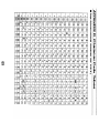
Appendixes contain information on general specifications, character code
tables and a list of commands.
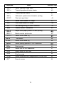
CONTENTS
Chapter 1 Unpacking the Printer . . . . . . . . . . . . . . . . . . . . . . . . . . . . . . . . . . . . . . . . . . . . . . . . . . . . . . . . . . . . . . . . . . . . .
1-1 Checking the Contents of the Box ...........................................................
1-2 Choosing a Place for the Printer ..............................................................
1-3 Removing the Protective Material ............................................................
1-4 Names and Functions of Parts ................................................................
Chapter 2 Before Setting Up ............................................................................
2-l Connecting the Power Supply to the Printer ............................................
2-2 Connecting the Host Computer to the Printer ..........................................
Chapter 3 Installing the Parts ..........................................................................
2
2
3
3
4
6
6
7
8
3-1 Installing the Roll Paper ...........................................................................
8
3-2 Adjusting the Paper-end Detector ............................................................ 10
3-3 Setting the DIP Switches ......................................................................... 12
III
Chapter 4 The Self Test . . . . . . . . . . . . . . . . . . . . . . . . . . . . . . . . . . . . . . . . . . . . . . . . . . . . . . . . . . . . . . . . . . . . . . . . . . . . . . . . . . . .
14
4-l Checking Operation with the Self Test . . . . . . . . . . . . . . . . . . . . . . . . . . . . . . . . . . . . . . . . . . . . . . . . . . . . 14
Chapter 5 Cautions while Using the Printer . . . . . . . . . . . . . . . . . . . . . . . . . . . . . . . . . . . . . . . . . . . . . . . . . . .
16
5-1 Panel Switches and Commands ..............................................................
5-2 Printable Area and Label Paper Conditions.. ...........................................
5-3 Miscellaneous Notes ................................................................................
5-4 Error Correction .......................................................................................
5-5 Cleaning the Head ...................................................................................
5-6 The Cover-open Detector ........................................................................
5-7 Removing Jammed Paper .......................................................................
16
17
18
20
23
24
24
Chapter 6 Software Control .............................................................................
25
6-l Printer Control ..........................................................................................
6-2 Command Descriptions ...........................................................................
6-3 Commands ..............................................................................................
6-4 Program Description ................................................................................
25
26
26
54
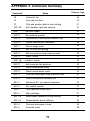
APPENDIX ..........................................................................................................
61
APPENDIX A General Specifications ...........................................................
APPENDIX B Connectors .............................................................................
APPENDIX C Interfaces ...............................................................................
APPENDIX D Character Code Tables.. ........................................................
APPENDIX E Command Summary ..............................................................
iv
61
65
67
69
72
1. SETTING UP
Chapter 1 Unpacking the Printer
1-1 Checking the Contents of the Box
g
Checking the parts
Remove the printer and other parts from the box.
•
•
Roll paper
•
Operator’s Manual
Printer
Make sure no parts are missing or damaged.
If you find any damaged or missing parts, please contact your dealer for assistance.
n Maintenance
Keep the packing case and packing materials in case you ever need to transport
or store your printer.
n Optional parts
Power supply (PS-130), Power supply DC cable (1.5 m)
2
1-2 Choosing a Place for the Printer
n
n
n
n
n
Avoid locations that are subject to direct sunlight or excessive heat (near
heaters).
Avoid using or storing the printer in places subject to excessive temperatures
or moisture.
Do not use or store the printer in a dusty or dirty location.
When setting up the printer, choose a stable, horizontal location.
Intense vibration or shock may damage the printer.
Ensure the printer has enough space to be used easily.
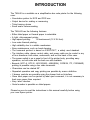
1-3 Removing the Protective Material
An orange plastic spacer is put into the printing mechanism section to protect the
printer from damage during transportation. Before you turn on the printer, be sure
to remove the spacer according to the following steps.
1. Open the printer cover.
2. Raise the head-open lever to remove the spacer.
3. Store it in the hollow space. Reinsert the spacer when transporting.
4. Lower the head-open lever.
Protective Material
Head-open Lever
3
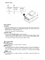
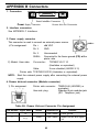
1-4 Names and Functions of Parts
n Part names
À Roll-paper cover
Á Operation panel
 Power connector
à Interface connector
Ä Drawer kick-out connector
Å DIP switches (* 1)
À
Á
Å
Â
Ã
Ä
* 1: The DIP switches are located behind the small cover on the bottom of the
printer.
n Operation panel
Panel switches
POWER
Press the POWER button to turn the printer ON and OFF. When the button is
pushed down, the power is on. When pressed again, the button returns to its
original position, turning the power off.
Do not turn the power off during printing.
PAPER FEED
Press the PAPER FEED button to feed roll paper.
Pressing the PAPER FEED button recovers from waiting state of label
ejection command (GS FF) execution or from self-test printing standby state.
You cannot feed paper when the printer cover is open.
l
l
l
Panel Lights (LED)
POWER (green)
The POWER light is on when power is turned on.
ERROR (red)
The ERROR light is on when the roll-paper cover is not closed completely, or
when the paper roll is near the end. The light blinks during an error condition,
or in the print-waiting state (for macro execution or for self-test printing standby
state).
PAPER (red)
The PAPER light is on when roll paper is not loaded, on when the paper roll is
near the end.
5
Chapter 2 Before Setting Up
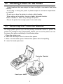
2-1
Connecting the Power Supply to the Printer
n Plugging in AC adapter
The printer must be connected to an external power supply.
Be sure to use a power supply unit that matches the specifications.
CAUTIONS:
Before connecting the printer to the power supply, make sure that the
voltage (24 VDC) and power specifications match the printer’s requirements.
Using an incorrect power supply can cause serious damage to the printer.
l
l
Connect the power unit according to the following procedure.
Make sure the printer and the power unit are turned off.
Plug the power cable’s connector into the printer’s power connector with the
arrow mark facing downward.
Remove the power cable by grasping the connector firmly at the arrow mark
and pulling straight out.
Plug the power cord into an outlet, and turn on the power unit.
l
Power Cable Connector
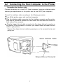
2-2 Connecting the Host Computer to the Printer
n Connecting the interface cable
Connect the printer to a host ECR (host computer) using an interface cable
matching the specifications of the printer and the host ECR (host computer).
Connect the interface cable according to the following procedure.
Turn off the printer, power unit, and host computer.
Plug the interface cable connector into the interface connector on the printer;
then insert a screwdriver between the rear rubber feet and fasten the screws on
both sides of the connector.
Plug the drawer kick-out cable connector into the drawer kick-out connector on
the printer (if this connector is covered, you cannot attach a drawer kick-out
cable to your printer).
Remove the drawer kick-out cable by pressing in on the connector’s clip and
pulling out.
•
Serial Interface Cable
Drawer Kick-out Connector
7
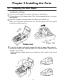
Chapter 3 Installing the Parts
3-1
Installing the Roll Paper
n Installing the roll paper
Be sure to use roll paper that matches the printer’s specifications.
Using scissors, cut the leading edge of the roll paper perpendicular to the paper
feed direction.
Open the roll-paper cover and raise the release lever toward you.
Make sure to pull the release lever out until the paper slot of the printer
mechanism will be faced up.
Paper Slot
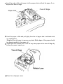
Load the roll paper while lightly pressing the right roll paper holder outward.
Release the holder after fitting the paper core onto the holder. Make sure the
roll paper turns freely.
When loading roll paper, make sure to insert so that it rotates in the correct
direction.
l
Correct
Incorrect
8
Insert the edge of the roll paper into the paper slot and feed the paper 5 cm
beyond the tear-off edge.
Tear-off -Edge
Paper Slot
Unroll the paper a little and pull lightly from the roll paper side to eliminate twist
or misalignment.
Retighten the roll paper to remove any slack. Both edges of the paper should
be aligned parallel to the paper roll.
Push down the release lever. Tear off any extra paper at the tear-off edge by
pulling the paper toward you.
Close the roll-paper cover.
3-2 Adjusting the Paper-end Detector
n The paper-end detector
The paper-end detector senses when the paper is nearing its end and turns on the
PAPER lamp.
The paper-end detector can be adjusted according the thickness of the paper.
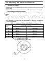
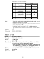
n How to adjust the paper-end detector
Roll paper may differ in spool size, so it may be necessary to adjust the paper-end
detector.
Use the specified thermal paper roll with a core inside diameter (d1) of 12 mm
and an outside diameter (d2) of 18 mm, or the specified thermal label paper
with a core inside diameter (d1) of 12 mm and an outside diameter (d2) of 22
mm.
The thickness of the spool can vary; use the table to determine the paper-end
detector adjustment.
Table 3-l. Adjustment Values of the Paper-end Detector
Adjustment
Value
Dimension of T (mm)
Specified thermal paper
Specified thermal label paper
#l
Approx. 0
Do not use
#2
Approx. 2
Approx. 0
#3
Approx. 4
Approx. 2
#4
Approx. 6
Approx. 4
#5
Approx. 8
Approx. 6
#6
Approx. 10
Approx. 8
d2 018 (specified thermal paper)
022 (specified thermal label paper)
10
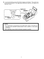
Loosen the adjusting screw that holds the paper-end detector. Then set the top
of the positioning plate to the appropriate adjustment position, and tighten the
adjusting screw.
NOTES:
The T dimensions corresponding to the adjustment values in the table are
calculated from standard measurements; some variations in the actual
mechanism.
After adjusting, ensure that the detector operates smoothly.
l
l
11
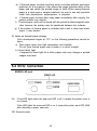
3-3 Setting the DIP Switches
n Locating the DIP switches
On the underside of your printer are a number of DIP switches that can be set to
perform a number of different functions.
You can change the function of your printer by turning DIP switches on or off.
Current DIP-switch settings are printed out during the self test.
The switches numbered from left to right are SW1 -1 through SW1 -10 (See figure
below).
Each switch functions as described in the lists on the following page.
l
l
l
l
n Setting the DIP switches
Follow these steps when changing DIP-switch settings.
Turn the printer power supply off. Always make DIP-switch setting changes
when the power supply is turned off.
Remove the screw to secure the small cover on the printer’s bottom.
Flip the DIP switches using tweezers or other narrow-ended tool.
Switches in the up position are ON; those in the down position are OFF.
NOTE:
Changes made with the power on have no effect until the power supply
is turned off and then on again.
l
12
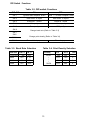
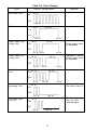
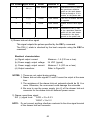
n DIP-Switch Functions
Table 3-2. DIP-switch Functions
ON
OFF
SW-1
Ignores data reception errors
Prints “?” for data reception errors
SW-2
Data buffer 45 bytes
Data buffer 4 Kbytes
SW-3
XON/XOFF control
DSR/DTR control
SW-4
With parity
without parity
SW-5
Even parity
Odd parity
DIP SW
SW-6
Change baud rate (Refer to Table 3-3)
SW-7
SW-8
Change print density (Refer to Table 34)
SW-9
SW-10
Thermal label paper
Table 3-3. Baud Rate Selection
Baud Rate
1200 bps
SW 1-6
SW 1-7
ON
ON
4800
OFF
O N
9600
ON
OFF
19200
OFF
OFF
Thermal paper
Table 3-4. Print Density Selection
Print Density
LIGHT
I
I
I
DARK
13
SW 1-8
SW 1-9
Level
ON
ON
1
OFF
OFF
2
ON
OFF
3
OFF
ON
4
Chapter 4 The Self Test
4-1
Checking Operation with the Self Test
n The purpose of the self test
The self test checks whether the printer has any problems.
When the printer does not function properly, please contact the dealer.
n The self test checks the following
l
l
l
Control circuit functions
Printer mechanism
Print quality
l
l
Control ROM version
DIP-switch settings
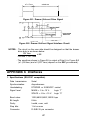
n Running the self test
Run the self test only when thermal roll paper or label paper is loaded the printer.
Make sure the roll-paper cover is closed and the roll paper is installed correctly.
Turn on the power while holding down the FEED switch. The self test begins.
The following contents are printed for printer current status printing first.
Control ROM version
DIP-switch settings
Interface settings
Print density
After printing the printer
current status, the printer
blinks the ERROR LED and
enters the test printing
standby state.
Press the FEED switch to
restart test printing.
l
l
l
l
After the printer completes
a certain number of lines, it
prints” *** completed **
* ", and stops printing automatically.
* The printer goes off-tine
during and after self-test
printing. Turn the power off
and on again to put the
printer on-line before
transmitting data from the
host computer.
Label paper (44%)
Thermal paper (44%)
Self test Printing Samples
14
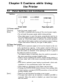
II. REFERENCE
Chapter 5 Cautions while Using
the Printer
5-1
Panel Switches and Commands
n Switches
(1) Power switch
[Function]
Turns the power supply on/off.
l The RAM is initialized after turning off the circuit power supply.
[Note]
l Do not touch the power supply switch during printing.
l When label paper is used, the printer automatically sets the label at the starting position for printing just after turning the power
switch on. When label paper is selected, the printer automatically detects label paper position and performs paper feeding.
(Paper feed amount varies by the type of label paper.)
(2) Paper-feed switch
If this switch is pressed, paper is fed one line based on the cur[Function]
rently specified line spacing. If this switch is held for 200 ms or
more, paper is fed as long as the switch is pressed, and stops
when the switch is released. If line spacing is set to 0, paper is
fed while the switch is pressed.
l The defined macro is executed when the switch is pressed in
the macro executing command standby state.
l Paper is fed by operating this switch, except during printing, in
an error state, and in the macro executing command standby
state.
l When label is selected, paper feeding is performed in label units
regardless of the predetermined paper feed amount.
l Paper feeding is performed at the paper near-end state.
l Pressing the PAPER FEED button recovers from waiting state
of label ejection command (GS FF) execution or from self-test
printing standby state.
[Note]
l Paper is not be fed when the printer cover is open.
l The paper-feed switch can be enabled or disabled with ESC c5
command. When this switch is disabled, you cannot feed paper
with the switch.
16
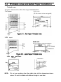
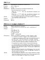
5-2 Printable Area and Label Paper Conditions
n Printable area
The print area must be within the range indicated below.
Roll paper
[Units: mm]
(All the numeric values are typical.)
Label paper
n Label paper conditions
Label paper
NOTE:
Hole dimensions
Do not use anything other than label rolls with the dimensions shown
above. Do not mix labels with different length in one label.
17
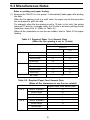
5-3 Miscellaneous Notes
n Notes on printing and paper feeding
(1) Because the TM-L60 is a line printer, it automatically feeds paper after printing
the data.
When the line spacing is set to a small value, the paper may be fed more than
the set amount to print the data.
For example, when the line spacing is set to 10 dots (10/180 inch), the printer
feeds just 10 dots for a carriage return; but 24 dots is fed when printing normal
characters using Font A. (Refer to Table 5-l.)
When all the characters on one line are rotated, refer to Table 5-2 for paper
feeding.
Table 5-1. Required Paper Feed Amount Dots
(When the line spacing is set to 10 dots)
Required Paper Feed Amount (dots)
Underline
Font A
Font B
without
with
Normal characters
24
32
Double-height
4 8
53
Double-width
2 4
32
Quadruple
48
53
Normal characters
17
24
Double-height
34
37
Double-width
17
24
Quadruple
34
37
Bit image
24
Table 5-2. Required Paper Feed Amount Dots
(When all the characters on one line are rotated)
Required Paper Feed Amount (dots)
Font A
Font B
Normal characters
12
Double-height
24
Double-width
12
Quadruple
24
Normal characters
9
Double-height
18
Double-width
9
Quadruple
18
18
(2) When the printer goes to the standby (data-waiting) state during printing, the
printer stops printing and feeding paper temporarily. When the printer restarts,
the paper may shift 1 to 3 dots at the start of printing. Graphics printing is
especially affected by this.
n Notes on the power supply
l
l
l
Turn the external power supply on after connecting it to the power supply
connector.
Be sure you do not connect the external power supply with the wrong polarity.
If it is connected incorrectly, the internal circuit fuse may blow or the external
power supply may be damaged.
The power supply voltage should be 24 VDC ±7%. The voltage fluctuation
between no-load and printing should be ±2% or less. If the power supply
voltage fluctuates more than this, print quality will be poor.
n Notes on handling the printer mechanism
l
l
l
l
l
l
Do not pull paper out (forward/backward directions) while the print head is
down.
The thermal elements of the head and driver IC are liable to be damaged;
avoid touching them with anything made of metal.
The areas around the print head and motor surface are very hot during and
just after printing; do not touch directly with your fingers.
Do not operate the head-open lever except when necessary.
Do not touch the surface of the head thermal elements directly with your
fingers. (Dust and dirt can stick to the surface, which will affect the thermal
elements.)
Thermal paper containing Na¯, K¯, and Cl¯ ions will affect the head thermal
elements. Be sure to use only the paper specified.
n Notes on handling thermal paper and label paper
(1) Notes on using thermal paper
Chemicals and oil that come into contact with the thermal paper may cause
discoloration, and can also cause the printing to fade.
Therefore, pay attention to the following:
a) Use water-based paste, starch paste, polyvinyl paste, or CMC paste when
gluing thermal paper.
b) Volatile organic solvents such as alcohol, ester, and ketone can cause
discoloration.
c) Some adhesive tapes may cause discoloration, and may also cause the
printed image to fade.
19
d) If thermal paper touches anything which includes phthalic acid ester
plasticizer for a long period, it can reduce the image formation ability of the
paper and can cause the printed image to fade. When storing thermal
paper in a card case or sample notebook, be sure to use only products
made from polyethylene, polypropylene, or polyester.
e) If thermal paper touches diazo copy paper immediately after copying, the
printed surface may discolor.
f) Thermal paper must not be stored with the printed surfaces against each
other because the printing may be transferred between the surfaces.
g) If the surface of thermal paper is scratched with a nail or other hard metal
object, it may discolor.
(2) Notes on thermal paper storage
Color development begins at 70°C, so the following precautions should be
taken.
a) Store paper away from high temperature and humidity.
Do not store thermal paper near a heater or in direct sunlight.
b) Avoid direct light.
If exposed to direct light for a while, paper color may change or printed
images may fade.
5-4 Error Correction
n ERROR LED (red)
On: If this LED lights when the near-end LED is off, it means the printer cover is
not closed.
If this LED lights the near-end LED is on, it means the printer went OFF-LINE
after detecting a paper near-end.
Off: Normal mode.
20
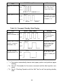
Table 5-3. Error Display
Recovery
ON/OFF Timing Pattern
Error
150 ms
RAM check error
Impossible to recover.
ON
OFF
150 ms
Transistor error
Impossible to recover.
1800 ms
150 ms
O N
OFF
150 ms
300 ms
Power supply, high
voltage error
ON
impossible to recover.
1500 ms
150 ms
(Power supply should
be inspected.)
OFF
150 ms
150 ms 300 ms
Power supply, low
voltage error
150 ms
impossible to recover,
1200 ms
ON
(Power supply should
be inspected.)
OFF
150 ms
Print head thermistor
error
ON
150 ms
300 ms
Impossible to recover.
900 ms
150 ms
OFF
150 ms
Internal data
processing error
300 ms
150 ms
Recovered by turning
the power off and on.
150 ms
ON
OFF
150 ms
Print head paper
out error
ON
1950 ms
Recovered by closing
the cover after
150 ms
inserting paper.
OFF
150 ms
1650 ms
21
ON/OFF Timing Pattern
Error
Print head overheating
Recovers automatically when the print
head temperature
150 ms
ON
error
Recovery
drops back down.
OFF
150 ms
Label paper out error
1350 ms
Recovered by closing
300 ms
ON
the printer cover after
specified label paper
is loaded. (*1)
OFF
900 ms
300 ms
Table 5-4. Command Standby State Display
ON/OFF Timing Pattern
Error
Waiting for
ON
macro execution (*2)
300 ms
Recovery
Recovered after
executing the
macro by pressing
the paper-feed
OFF
switch.
300 ms
ejection command
Recovered by pressing the paper feed
600 ms
Waiting state of label
ON
switch to execute
execution (*2)
label ejection
OFF
command.
600 ms
Self-test printing
standby state (*3)
Recovered by press-
1.2 s
ing the paper feed
ON
switch to restart printing.
OFF
1.2 s
( * 1): The printer automatically detects label paper position and performs paper
feeding.
( * 2): See 6-3 Commands for the macro command and the label ejection command.
( * 3): See 4-l Checking Operation with the Self Test for self test printing standby
state.
22
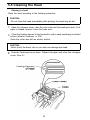
5-5 Cleaning the Head
n Cleaning the head
Clean the head according to the following procedure.
CAUTION:
Do not clean the head immediately after printing; the head may be hot.
l
Open the roll-paper cover, raise the auto-cutter and the head-open lever. If roll
paper is loaded, remove it from the head area.
l
Clean the heating element of the head with a cotton swab containing an alcohol
solvent (ethanol, methanol, or IPA).
Clean the cutter also with an alcohol solvent.
CAUTION:
Never touch the head; oils on your skin can damage the head.
l
Push the head-open lever down. Reload roll paper and close the roll-paper
cover. See 3-l.
23
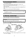
5-6 The Cover-open Detector
n The cover-open detector
This unit has an cover-open detector located inside the roll-paper cover.
Data is not printed when the printer cover is open.
Opening the cover sets the printer OFF-LINE; data cannot be received when the
printer is OFF-LINE.
Paper cannot be fed with the paper-feed switch when the roll-paper cover is
open.
Closing the cover sets the printer ON-LINE automatically.
l
l
l
l
NOTE:
The roll-paper cover cannot be closed unless the head-release lever and the
head-open lever are down.
5-7 Removing Jammed Paper
Remove jammed paper according to the following steps.
Open the roll-paper cover and raise the head-open lever.
CAUTION:
The print head is very hot immediately after printing.
Always remove jammed paper after the print head has cooled.
l
Or remove the screw
and take the paper entrance away, instead of step .
Remove any jammed paper.
Push the head-open lever down. Reload roll paper and close the roll-paper
cover. See 3-1 to .
24
Chapter 6 Software Control
6-1 Printer Control
n Controlling the printer with commands
The printer is controlled by “commands” that can change the size of the characters, and perform other functions.
See the character code table.
There are two types of commands.
One-byte commands
HT Horizontal tab
Print and line feed
LF
l
l
l
l
Several-byte commands
ESC SP
Set character right-side spacing
Set line spacing using minimum units
ESC 3 n
n How to use this table.
Horizontal by vertical hex
ie. 4A = J
< >H
denotes hexadecimal
< >
denotes decimal numbers
(Refer to APPENDIX D Character Code Tables)
Hexadecimal
I
Binary
I
Decimal numbers
Hexadecimal Binary
25
6-2 Command Descriptions
n Command descriptions
XXX Command
[Name]
The name of the command.
[Format]
The code sequence.
In this description, < > H denotes hexadecimal numbers, < > denotes decimal numbers and < > B denotes binary numbers.
[ ] k indicates the contents of the [ ] should be repeated k times.
[Range]
The allowable range for the arguments.
[Description]
Description of the command function.
[Notes]
(Included only when necessary.)
[Default]
The default values for the commands.
[Reference]
Related commands.
[Example]
Example of using the commands.
6-3 Commands
HT
[Name]
[Format]
[Description]
Horizontal tab
<09> H
Moves the print position to the next horizontal tab position.
This command is ignored unless the next horizontal tab position
has been set.
Horizontal tab positions are set using ESC D.
The default horizontal tab positions are at intervals of 8 characters (9th column, 17th, 25th ...) for Font A.
ESC D
l
[Notes]
l
l
[Reference]
26
LF
[Name]
[Format]
[Description]
[Reference]
Print and line feed
<OA> H
Prints the data in the print buffer and performs 1 line feed based
on the current line spacing.
l Sets the print starting position to the beginning of the line.
ESC 2, ESC 3, 5-3 Miscellaneous Notes
FF
[Name]
[Format]
[Description]
[Notes]
[Reference]
Print and position label to start printing
<OC> H
Prints the data in the print buffer and positions the next label for
printing.
l This command is effective only when label printing mode is selected.
l This command will not work correctly after a label has been
moved manually using the paper feed knob. Position the label
using the paper feed switch or issue GS <.
l A FF or GS FF command must be sent after transmitting print
data for one label.
GS FF
ESC SP n
[Name]
[Format]
[Range]
[Description]
[Notes]
[Default]
Set character right-side spacing
<1B> H <20> H <n>
0
n 32
Sets the character right-side spacing in dot units (1/180 inch units).
l The character right-side spacing for double-width mode is twice
the set value.
n=0
ESC ! n
[Name]
[Format]
[Range]
[Description]
Set print mode
<1B> H <21> H <n>
0
n
255
Sets a print mode.
27
l
Each bit of n is used as follows:
Value
[Note]
Bit
Function
0
1
0
Character font
Font A
Font B
1
Undefined
2
Undefined
3
Emphasized
Canceled
Set
4
Double-height
Canceled
Set
5
Double-width
Canceled
Set
6
Undefined
7
Underline
Canceled
Set
When both double-height mode and double-width mode are set,
quadruple characters are printed.
Underlines can be printed for all characters, but not for the
space skipped by an HT.
Underlines cannot be printed for 90° rotated characters.
The thickness of an underline is set by ESC - (default value =
1.)
n=0
ESC E, ESC F, ESC -
l
l
l
l
[Default]
[Reference]
ESC $ n1 n2
[Name]
[Format]
[Range]
[Description]
Set absolute position
<1B> H <24> H <n1> <n2>
0
n1
255
0
n2 1
Sets the print starting position to the specified number of dots
(1/180 inch units) from the beginning of the line.
Divide the number of dots by 256. The integer answer is n2 and
the remainder is n1. Therefore, the print starting position becomes n1 + n2 X 256 from the beginning of the line.
Any specification that exceeds the printable area is ignored.
Not defined
ESC ¥
l
[Notes]
[Default]
[Reference]
l
28
ESC % n
[Name]
[Format]
[Range]
[Description]
Select/cancels user-defined character set.
<1B> H <25> H <n>
0 n
255
Selects or cancels the user-defined character set.
Only the lowest bit of n is valid.
When n = < ******* 1>B, the user-defined character set
is selected.
When n = < ******* 0>B, the user-defined character set
is canceled (and the internal character set is selected.)
The user-defined characters and a down-loaded bit image can
not be defined at the same time.
n=0
ESC &
l
[Notes]
[Default]
[Reference]
l
ESC & s n m [a[p] s Xa]m-n+l
[Name]
[Format]
[Range]
[Description]
Define user-defined characters
<1B>H<26>H<s><n><m>[<a><p1><p2>---<psXa>]m-n+1
s=3
32 n
m
126
0 a 12 (Font A)
0 a 9 (Font B)
0 p1 ... psXa 255
Defines user-defined characters for ANK character codes.
“s” specifies the number of bytes in the vertical direction.
. “n” specifies the beginning ASCII code for the definition and "m"
the final code. If only one character is defined, use n = m.
The allowable character code range is from ASCII code <20> H
to <7E> H and the maximum number of characters is 95.
“a” specifies the number of dots in the horizontal direction.
“p” is the dot data for the characters. The pattern for a dots is in
the horizontal direction from the left side. The remaining dot
pattern on the right side is space. The amount of data to be
defined is s X a.
After user-defined characters are defined once, they are available until another definition is made, until ESC @ is executed, or
until the printer is turned off.
The user-defined characters and a down-loaded bit image
cannot be defined at the same time. If this command is executed, the down-loaded bit image will be cleared.
l
l
l
l
l
[Notes]
l
29
[Default]
[Reference]
[Example]
The same as the internal character set.
ESC %
Font A is selected:
l
l
Font B is selected.
ESC * m n1 n2 [d] k
[Name]
[Format]
[Range]
Set bit image mode
<1B>H<2A>H<m><n1><n2>[<d>]k
m = 0, 1, 32, 33
O n1 255
O n2 3
O d 255
k=n1+256Xn2(m=0,1)
k=(n7+256Xn2)X3(m=32,33)
30
[Description]
Sets the bit-image mode using m and the number of dots using
n1 and n2.
l Divide the number of dots to be printed by 256. The integer answer is n2 and the remainder is n1. Therefore, the number of
dots in the horizontal direction is: n1 + 256 X n2.
l If the bit-image data input exceeds the number of dots to be
printed on a line, the excess data is ignored.
l "d" indicates the bit image data. Set a corresponding bit to 1 to
print a dot, otherwise set it to 0.
l The bit image modes selectable by m are as follows:
Vertical Direction
m
Mode
Number of
dots
Dot
Density
Horizontal Direction
Density
Maximum
Number of Dots
Normal Label
0
8-dot single-density
8
60 DPI
90 DPI
192
184
1
8-dot double-density
8
80 DPI
180 DPI
384
368
32
24-dot single-density
24
180 DPI
90 DPI
192
184
33
24-dot double-density
24
180 DPI
180 DPI
384
368
[Notes]
If m is out of range, n1 and the data following will be processed
as normal data.
l After printing a bit image, the printer returns to normal data processing mode.
l The relationship between the image data and the dots to be
printed is as follows:
.
Single-density
31
Double-density
l 24-dot bit image
ESC 2
[Name]
[Format]
[Description]
Set 1/6 inch line spacing
<1B>H<32>H
Sets the line spacing to 1/6 of an inch.
ESC 3 n
[Name]
[Format]
[Range]
[Description]
[Default]
[Reference]
Set line spacing using minimum units
<1B>H<33>H<n>
0 n 255
Sets the line spacing to n/360 of an inch.
n = 60 (1/6 inch)
5-3 Miscellaneous Notes
ESC = n
[Name]
[Format]
[Range]
[Description]
Select device
<1B>H<3D>H<n>
0
n 255
Selects a device to receive data from the host computer.
If the printer is not selected, the TM-L60 ignores all received
data (the data is lost) until it is selected by this command.
l
32
l
Each bit of n is used as follows:
Value
[Notes]
[Default]
Bit
Device
0
1
0
Printer
Invalid
Valid
1
Undefined
2
Undefined
3
Undefined
4
Undefined
5
Undefined
6
Undefined
7
Undefined
Even when the printer is not selected, it may enter the BUSY
state due to printer operation.
n=1
l
ESC @
[Name]
[Format]
[Description]
[Note]
Initialize printer
<1B>H<40>H
Clears the data in the print buffer and resets the printer mode (to
the same state as when the power is turned on).
l The DIP switches are not read again.
l The data in the receive buffer is not cleared.
l Adjustment amount of the label starting position using < GS A >
command is not cleared.
ESC D [n]kNUL
[Name]
[Format]
[Range]
[Description]
Set horizontal tab positions
<1B>H<44>H[<n>]k<00>H
1 n 255
0
k 32
Sets horizontal tab positions.
l "n” specifies the column number from beginning of the line for
setting a horizontal tab position.
[n= (Column number) - 1]. For example, when a tab is to be set
at column 9, n = 8.
l "k" indicates the total number of horizontal tab positions to be
Set.
33
A horizontal tab position is stored as the absolute value of
(character width X n ) measured from the beginning of the line.
The character width includes the character right-side spacing,
and double-width characters should be set with twice the width
of normal characters.
Up to 32 tab positions can be set. Data which exceeds 32 tab
positions will be ignored.
Set <n> k in ascending order and place a NUL code <00> H at
the end.
ESC D NUL clears all tabs. Any HT commands received after
clearing will be ignored.
[Notes]
When a data value <n> k is less than or equal to the preceding
value <n> k-1, the setting is considered to be finished. In this
case, the following data is processed as normal data.
When a data value <n> k exceeds the number of characters
printable on one line, the setting is considered to be finished. In
this case, the following data is processed as normal data.
Horizontal tab positions remain unchanged if the character
widths are changed after setting the horizontal tab positions.
[Default]
The default tab positions are at interval of 8 characters (9th column, 17th, 25th, ...) for Font A.
[Reference] HT
l
l
l
l
l
l
l
ESC E n
[Name]
[Format]
[Range]
[Description]
Select/cancel emphasized mode
<1B>H<45>H<n>
0 n
255
Prints or cancels the emphasized characters.
This command is available for all character types.
When emphasized mode is selected, one dot is added to the
right side of the dots in normal mode.
Only the lowest bit of n is valid.
When n = < * * * * * * * 1>B, the emphasized characters are
selected.
When n = <* * * * * * * 0>B, the emphasized characters are
canceled.
ESC !
l
l
l
[Reference]
34
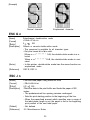
[Example]
Emphasized character
Normal character
ESC G n
[Name]
[Format]
[Range]
[Description]
Select/cancel double-strike mode
<1B>H<47>H<n>
0 n
255
Selects or cancels double-strike mode.
This command is available for all character types.
Only the lowest bit of n is valid.
When n = < * * * * * * * 1>B, the double-strike mode is s e lected.
When n =<* * * * * * * 0>B, the double-strike mode is canceled.
In this printer, double-strike mode has the same function as
emphasized mode.
ESC E, ESC H
l
l
[Notes]
[Reference]
l
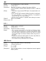
ESC J n
[Name]
[Format]
[Range]
[Description]
Print and feed paper using minimum units
<1B>H<4A>H<n>
0 n 255
Prints the data in the print buffer and feeds the paper n/360
inches.
The predetermined line spacing remains unchanged.
Sets the print starting position to the beginning of the line.
When the paper-feed amount which specifies over a range of
the label paper length is set, the paper is fed to the beginning
print position of the next label paper.
Not defined.
5-3 Miscellaneous Notes
l
l
l
[Default]
[Reference]
l
35
ESC R n
[Name]
[Format]
Select international character set
<1B>H<52>H<n>
[Range]
0
[Description]
n
n selects an international character set from the following table.
n
0
1
2
3
4
5
6
7
8
9
10
[Default]
[Reference]
10
Character Set
U.S.A.
France
Germany
U.K.
Denmark I
Sweden
Italy
Spain
Japan
Norway
Denmark II
n=0
APPENDIX D Character Code Tables
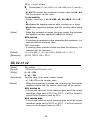
ESC V n
[Name]
[Format]
[Range]
[Description]
[Default]
Set/cancel 90° cw rotated characters
<1B>H<56>H<n>
0 n 1
Sets or cancels the 90° cw rotation of characters.
l When n = 1, 90° cw rotated characters are set.
l When n = 0, 90° cw rotated characters are canceled.
n=0
36
ESC ¥ n1 n2
[Name]
[Format]
[Range]
[Description]
Set relative position
<1B>H<5C>H<nl><n2>
0 n1 255
0
n2 255
Moves the print starting position to the specified number of dots
(1/180 inch units) from the current position.
A positive number specifies movement to the right, and a
negative number specifies movement to the left.
Negative numbers are specified using the supplement of N:
-N = 65536 - N
Divide the number of dots by 256. The integer answer is n2 and
the remainder is nl.
Any specification exceeding the printable area will be ignored.
Not defined
ESC $
l
l
l
[Notes]
[Default]
[Reference]
l
ESC - n
[Name
[Format]
[Range]
[Description]
Turn underline mode on/off
<1B>H<2D>H<n>
O n 2
Turns underline mode on/off.
. When n = 0, underline mode is turned off.
When n = 1, underline mode (1 -dot line thickness) is selected.
When n = 2, underline mode (2-dot line thickness) is selected.
Underlines can be printed for all characters, but not for the
space skipped by an HT.
Underlines cannot be printed for 90° cw rotated characters.
ESC !
l
l
[Notes]
l
l
[Default]
ESC a n
[Name]
[Format]
Align positions
<1B>H<61>H<n>
[Range]
[Description]
Aligns all the data in one line to the specified position.
37
l
[Notes]
[Default]
[Example]
n specifies the alignment as follows:
n
Position
0
Align left
1
Align center
2
Align right
Valid only when input at the beginning of a line.
n=0
l
Align right
Align center
Align left
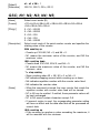
ESC c 4 n
[Name]
[Format]
Select paper detectors to stop printing
<1B>H<63>H<34>H<n>
[Range]
[Description]
Selects the paper detectors used to stop printing.
Each bit of n is used as follows:
l
Value
Bit
Function
0
1
0
Journal near-end
Invalid
Valid
1
2
Undefined
Undefined
3
Undefined
4
Undefined
5
Undefined
6
Undefined
Undefined
7
38
l
[Notes]
[Default]
In the TM-L60, only the journal near-end detector can be selected and only the lowest bit of n is valid.
When a paper-end is detected by the journal detector, the
printer goes OFF-LINE after printing stops.
l If a paper-end is detected by paper detectors when thermal label
paper is selected, the printer goes OFF-LINE after printing data
for one label.
n = 0
l
ESC c 5 n
[Name]
[Format]
Enable/disable panel switches
<1B>H<63>H<35>H<n>
[Range]
[Description]
[Notes]
[Default]
Enables or disables the paper-feed switch.
l Only the lowest bit of n is valid.
When n = <* * * * * * * 0>B, the paper feed switch is enabled.
When n = < * * * * * * * 1>B, the paper feed switch is disabled.
l If the panel switches are disabled by this command, the paper
feed switch is disabled. Therefore, paper cannot be fed with the
paper feed switch.
n = 0
ESC d n
[Name]
[Format]
[Range]
[Description]
[Default]
[Reference]
Print and feed paper n lines
<1B>H<64>H<n>
Prints the data in the print buffer and performs n lines feeds.
l Sets the print starting position to the beginning of the line.
l The predetermined line spacing remains unchanged.
Not defined.
5-3 Miscellaneous Notes
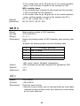
ESC p m n1 n2
[Name]
[Format]
[Range]
Generate pulse
<1B>H<70>H<m><n1><n2>
m=O,1
39
[Description]
The pulse defined by nl and n2 is output on connector pin m.
m is specified as follows:
l
m
l
Connector pin
0
Drawer kick-out connector pin 2
1
Drawer kick-out connector pin 5
ON time is nl X 2 ms and OFF time is n2 X 2 ms.
The circuit on the user side should be designed so that the
drawer drive duty is as shown below.
l
ON time
(ON time + OFF time)
[Notes]
[Default]
It is recommended that n2 be four times as much as nl or more.
If m is out of range, the printer reads n1 and n2 but does not
output a pulse.
Neither m, n1, nor n2 is defined.
l
ESC t n
[Name]
[Format]
Select character code table
<1B>H<74>H<n>
[Range]
[Description]
[Default]
[Reference]
Selects page n from the character code table.
n=0
APPENDIX D Character Code Tables
ESC u n
[Name]
[Format]
[Range]
[Description]
Transmit printer status
<1B>H<75>H<n>
n=0
Transmit the current status of connector pin.
n is specified as follows:
l
n
Connector pin
0
Drawer kick-out connector pin 3
40
[Notes]
l
l
l
l
l
The transmitted status is only one byte and the data is as shown
in the following table.
If nothing is connected with Drawer kick-out connector, bit 0 of n
is always “1".
When DTR/DSR control is selected, one byte is transmitted after confirming that the host computer is ready to receive data
(DSR is SPACE).
When XON/XOFF control is selected, one byte is transmitted
without checking the DSR signal.
When DTR/DSR control is selected, if the host computer is not
ready to receive data (DSR is MARK), the printer waits until it
becomes ready.
Value
Bit
Function
0
1
0
Pin 3 level
"LOW"
"HIGH"
1
Undefined
2
Undefined
3
Undefined
4
Unused
5
Undefined
6
Undefined
7
Undefined
Fixed to 0
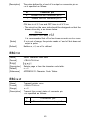
ESC v
[Name]
[Format]
[Description]
[Notes]
Transmit printer status
<1B>H<76>H
The current printer status is transmitted to the host computer.
The transmitted status is only one byte and the data is as shown
in the following table.
When DTR/DSR control is selected, one byte is transmitted after confirming that the host computer is ready to receive data
(DSR is SPACE).
When XON/XOFF control is selected, one byte is transmitted
without checking the DSR signal.
When DTR/DSR control is selected, if the host computer is not
ready to receive data (DSR is MARK), the printer waits until it
becomes ready.
l
l
l
l
41
Value
B i t
0
1
Function
0
1
Journal near-end Paper is present
Paper is out
Undefined
2
Unused
3
Undefined
4
Unused
5
Undefined
6
Undefined
7
Undefined
Fixed to 0
Fixed to 0
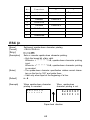
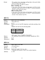
ESC {n
[Name]
[Format]
Set/cancel upside-down character printing
<1B>H<7B>H<n>
[Range]
[Description]
[Notes]
[Default]
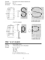
[Example]
Sets or cancels upside-down character printing.
l Only the lowest bit of n is valid.
When n = < * * * * * * * 1>B, upside-down character printing
is set.
When n = <* * * * * * * 0>B, upside-down character printing
is canceled.
l The upside-down character specification rotates normal characters on the line by 180° and prints them.
l Valid only when input at the beginning of a line.
n = O
When upside-down character
printing is canceled.
When upside-down
character printing is set.
A B C D E F G
0 1 2 3 4 5 6
Paper-feed direction
42
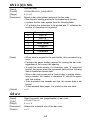
GS FF
[Name]
[Format]
[Description]
[Notes]
Print and eject label
<1D>H<OC>H
Prints the data in the print buffer on the label and ejects it.
l Ejects the label until it can be peeled off by fingers.
l After ejection, an error LED is lit and waits until the paper feed
switch is pressed.
l When the paper feed switch is pressed, it is assumed that the
label has been peeled off, and then paper feeding is performed
in the reverse direction to set the next label at the starting position for printing.
l After checking the error LED is lit, remove the label and then
press the paper feed switch once.
l This command is effective only when “label print” is selected.
l A FF or GS FF command must be sent after transmitting print
data for one label.
[Reference] FF
GS*n1n2[d]n1xn2x8
[Name]
[Format]
Define down-loaded bit image
<1D>H<2A>H<n1><n2>[<d]n1Xn2X8
[Range]
[Description]
Defines a down-loaded bit image with the number of dots specified by nl and n2.
l
[Notes]
[Reference]
The number of dots in the horizontal direction is n 1 X 8, and in
the vertical direction is n2 X 8.
l “d" specifies the bit image data.
l After a down-loaded bit image is defined once, it is available
until another definition is made, until ESC @ is executed, until
ESC & is executed, or the printer is turned off.
l The relationship between the bit image data and the transmitted dots is as follows:
l The user-defined characters and a down-loaded bit image cannot be defined at the same time. If this command is executed,
the user-defined characters will be cleared.
GS/
43
GS/m
[Name]
[Format]
Print down-loaded bit image
<1D>H<2F>H<m>
[Range]
[Description]
Prints a down-loaded bit image using the mode specified by m.
l m selects the print mode from the following table.
m
[Notes]
l
l
l
l
l
[Default]
[Reference]
Mode
Vertical Direction
Horizontal Direction
Dot Density
Dot Density
0
Normal mode
180 DPI
180 DPI
1
Double-width mode
180 DPI
90 DPI
2
Double-height mode
90 DPI
180 DPI
3
Quadruple mode
90 DPI
90 DPI
If any data is present in the print buffer, this command is ignored.
If a down-loaded bit image has not been defined, this command
is ignored.
If the down-loaded bit image data exceeds one line, the exceeds image data will not be printed.
The user-defined characters and a down-loaded bit image cannot be defined at the same time.
If the down-loaded bit image data exceeds label paper, it is
printed on the next label.
Not defined.
GS*
GS :
Set starting/ending of macro definition
<1D>H<3A>H
Specifies the starting or ending of the macro definition.
If this command is received while defining the macro, it ends the
definition.
l If the macro range exceeds 2048 bytes, the exceeds data is not
[Notes]
defined.
l Even if the ESC @0 command (initialize the printer) is performed,
the macro definition is not cleared. Therefore, it is possible to
include ESC @ in the macro definition.
l Normal printing operation is possible while defining the macro.
[Default]
Macro is not defined.
[Reference] GS
[Name]
[Format]
[Description]
GS <
[Name]
[Format]
[Description]
[Notes]
Initialize printer mechanism
<1D>H<3C>H
Positions the label for printing.
l This command takes effect on the third and following labels.
This is because the difference in detection level between label
and base sheet is determined using the first label on a sheet
and the label length and distance between labels using the second label.
l Because the maximum label length is 4 inches, any labels exceeding 4 inches in length will cause error.
l The contents set by commands will not change.
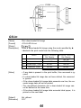
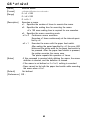
GS A m n
[Name]
[Format]
[Range]
[Description]
Adjust label paper position to start printing
<1D>H<41>H<m><n>
0 ≤ m ≤ 255
0 ≤ n ≤ 255
Sets the label position in terms of adjustment amount against
default position.
45
“m indicates adjusting direction.
When m = < * * * * * 0>B, positioning is adjusted in the
normal direction.
When m = <* * * * * * 0>B, positioning is adjusted in the
reverse direction.
"n” means the adjustment amount. It is n/360 inches.
The setting beyond the tip of a label is not available. If the
adjustment amount that goes beyond the label tip is specified,
the starting position will be set to the label tip.
Thus, any adjustment amount that will cause the printing width
on a label to be narrower than 255/360 inches (see the figure
below) cannot be set. Specifying such an amount will cause the
starting position to be set at 255/360 inches.
The default setting for the starting position is about 1.5 mm be
low the label tip.
This command is effective only when ‘label print” is selected.
Make sure to set the starting position by considering the alignment of the starting position will be split out approx. ±1 mm be
cause the paper is bent.
This command is valid only after setting for the starting position
by executing commands (FF, GS FF, GS <), pressing the PAPER FEED switch or turning the power on.
When position is adjusted in the reverse direction, the position of
the first label may shift approx. ±1 mm. To prevent this, feed the
first label through the machine without printing on it.
u
l
l
[Notes]
l
l
l
l
l
l
b
•••••••••
default
position
b Starting position
[Default]
None
[Reference]
FF, GS FF
I
I
(set by this command
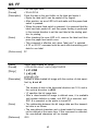
GS C 0 m n
[Name]
[Format]
[Range]
[Description]
Select counter print mode
<1D>H<43>H<30>H<m><n>
0 ≤ m≤ 5
0≤ n≤ 2
Selects print mode for the serial number counter.
l "m" indicates the number of digits to be printed.
m = O:
Prints the actual digits indicated by numerical value.
In this case “n” has no meaning.
46
l
m = 1 to 5: The maximum number of digits to be printed. When
the numerical value of the counter value is larger
than that specified by this command, prints lower
“m” digits of the counter value.
“n” specifies the printing position within the entire range of
printed digits.
n = O:
Prints with right adjusted. The empty specified
digits will be filled with spaces.
n =1 :
Prints with right adjusted. The empty specified
digits will be filled with is.
n = 2:
Prints with left adjusted. The empty specified digits
will be filled with spaces.
m=3, n=O
[Example]
m=3, n = 1
m=3, n=2
∆ indicates space
[Notes]
[Default]
[Reference]
If “m” or “n” is set outside of the defined range, that setting has
no effect.
m = 0
GS Cl, GS C2, GS c, GS C;
l
GS C1 n1 n2 n3 n4 n5 n6
[Name]
[Format]
[Range]
[Description]
Select count mode (A)
<1D>H<43>H<31>H<n1><n2><n3><n4><n5><n6><
0 ≤ n1 ≤ 2 5 5
O ≤ n2 ≤ 2 5 5
O ≤ n3 ≤ 2 5 5
0 ≤ n4 ≤ 255,
O ≤ n5 ≤ 2 5 5
O ≤ n6 ≤ 2 5 5
Selects count mode for the serial number counter.
With count-up
Counts up if n1 + n2x 256 < n3 + n4 x 256, n5 ≠ 0, and n6 ≠ 0.
n1 + n2 x 256 means the minimum counter value and n3 + n4 x
256 the maximum counter value.
l
l
47
With count-down
l Counts down n1 + n2 x 256 > n3 + n4 x 256, n5 ≠ 0, and n6 ≠
0.
n1 + n2 x 256 means the maximum counter value and n3 + n4 x
256 the minimum counter value.
To stop counting
Stops counting if n1 + n2 x 256 = n3 + n4 x 256, n5 = 0, or n6 =
0.
n5 indicates the stepping amount when counting up or down.
n6 indicates repetition number with the counter value being
fixed.
When this command is issued, the inner counter that indicates
the repetition number specified by n6 will be cleared.
With count-up
If counting up reaches a value exceeding the maximum, it is
resumed with the minimum value.
With count-down
If counting down reaches a value less than the minimum, it is
resumed with the maximum.
n1 + n2 x 256 = 1, n3 + n4 x 256 = 65535, n5 = 1, n6 = 1
GS CO, GS C2, GS c, GS C;
l
l
l
l
[Notes]
l
l
l
[Default]
[Reference]
GS C2 n1 n2
[Name]
[Format]
[Range]
[Description]
Set counter
<1D>H<43>H<32>H<n1><n2>
0 ≤ n1 ≤ 2 5 5
0 ≤ n2 ≤ 2 5 5
Sets the value of the serial number counter.
n1 + n2 x 256 is the counter value.
When this command is issued, the inner counter that counts
repetition number with the counter value fixed will be cleared.
With counting up
If the counter value set by this command goes out of the counter
operation range set by GS Cl or GS C;, it will be forced to
convert to the minimum value by GS c.
With counting down
If the counter value set by this command goes out of the counter
operation range set by GS Cl or GS C;, it will be forced to
convert to the maximum value by GS c.
l
[Notes]
l
l
l
48
[Default]
[Reference]
n1 + n2 x 256 = 1
GS CO, GS Cl, GS c, GS C;
GSC; N1; N2; N3; N4; N5;
[Name]
[Format]
[Range]
[Description]
Select count mode (B)
<1D>H<43>H<3B>H<N1><3B>H<N2><3B>H<N3><3B>H
<N4><3B>H<N5><3B>H
0 ≤ N1 ≤ 65535
0 ≤ N2 ≤ 65535
0 ≤ N3 ≤ 255
0 ≤ N4 ≤ 255
0 ≤ N5 ≤ 65535
Select count mode of the serial number counter and specifies the
starting value of the counter.
With counting up
Counts up if N1<N2, N3 ≠ 0, and N4 ≠ 0.
N1 means the minimum value of the counter, and N2 the
maximum value.
With counting down
Counts down if N1>N2, N3 # 0, and N4 ≠ 0.
N1 means the maximum value of the counter, and N2 the
minimum value.
To stop counting
Stops counting when N1 = N2, N3 = 0, or N4 = 0.
N3 indicates stepping amount while counting up or down.
N4 indicates repetition number with the counter value fixed.
N5 indicates the counter value.
When this command is issued, the inner counter that counts the
repetition number with counter value fixed will be cleared.
N7 to N5 can be omitted. If omitted, those parameter values will
be kept unchanged.
N7 to N5 cannot contain characters except O-9.
If incorrect syntax is used, the corresponding parameter setting
will have no effect and the data after that will be processed as
normal data.
With counting up
If the counting up reaches a value exceeding the maximum, it
will be resumed with the minimum.
l
l
l
l
l
l
l
l
[Notes]
l
l
l
l
l
49
If the counter value set by N5 goes out of the counter operation
range, it will be forced to convert to the minimum by GS c.
With counting down
If the counting down reaches the value less than the minimum,
it will be resumed with the maximum.
If the counter value set by N5 goes out of the counter operation
range, it will be forced to convert to the maximum by G3 c.
N1 = 1, N2 = 65535, N3 = 1, N5 =1
GS CO, GS Cl, GS C2, GS c
l
l
l
[Default]
[Reference]
GS H n
[Name]
[Format]
[Range]
[Description]
Select printing position of HRI characters
<1D>H<48>H<n>
O≤n≤3
Selects the printing position of HRI characters when printing a bar
code.
n selects the printing position from the following table.
l
n
Printing position
0
Not printed
1
Above the bar code
2
Below the bar code
3
Both above and below the bar code
HRI means Human Readable Interpretation.
HRI characters are printed using the font specified by GS f.
n=0
GS f
l
[Notes]
[Default]
[Reference]
l
GS c
[Name]
[Format]
[Description]
Print counter
<1D>H<63>H
Prints the serial counter.
Sets the current counter value in the print buffer as a print data
(character string) and then counts up or down the counter based
on the count mode set.
l
50
[Notes]
The syntax to be used when setting data in the print buffer
should be based upon GS CO.
For count mode, see GS Cl or GS C;.
With counting up
If the counter value set by this command goes out of the counter
operation range set by GS Cl or GS C;, it will be forced to
convert to the minimum by GS c.
With counting down
If the counter value set by this command goes out of the counter
operation range set by GS C1 or GS C;, it will be forced to
convert to the maximum by GS c.
l
l
l
l
GS f n
[Name]
[Format]
[Range]
[Description]
Select font for HRI characters.
<1D>H<66>H<n>
n = 0, 1
Selects a font for the HRI characters used when printing a bar
code.
n selects the font from the following table.
l
n
Font
0
Font A
1
Font B
HRI means Human Readable Interpretation.
HRI characters are printed at the position specified by GS H.
n=0
GSH
l
[Notes]
[Default]
[Reference]
l
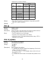
GS h n
[Name]
[Format]
[Range]
[Description]
Select height of bar code
<1D>H<68>H<n>
1 ≤ n ≤ 255
Selects the height of the bar code.
n specifies the number of dots in the vertical direction.
n= 162
l
[Default]
51
GS k n [d] k NUL
[Name]
[Format]
[Range]
[Description]
Print bar code
<1D>H<6B>H<n> [<d>]k<00>H
0≤n≤6
Selects a bar code system and prints the bar code.
l Sets the print starting position to the beginning of the line.
l n selects the bar code system from the following table.
l “d” indicates the characters to be printed and “k” indicates the
number of characters to be printed.
n
0
Bar code system
UPC-A
1
2
UPC-E
3
4
[Notes]
[Default]
JAN13 (EAN)
5
JAN8 (EAN)
CODE39
ITF
6
CODABAR
When data is present in the print buffer, this command is ignored.
l Performs the paper feeding required for printing the bar code,
regardless of the current line spacing.
l In each bar code system, if a character code ”d” cannot be
printed, the printer prints the processed data and the following
data is treated as normal data.
l When a bar code system with a fixed number of printing characters is selected, the number of characters "K" shouId be agreed
with that number.
l If the horizontal size exceeds one line, the excess data is not
printed.
l If data exceeds label paper, it is printed on the next label.
n=0
l
GS w n
[Name]
[Code]
[Range]
[Description]
[Default]
Select horizontal size (magnification) of bar code.
<1D>H<77>H<n>
2≤n≤4
Selects the horizontal size of the bar code.
n=3
52
GS ^ n1 n2 n3
[Name]
[Format]
Execute macro
<1D>H<5E>H<n1><n2><n3>
0 ≤ n1 ≤ 255
0 ≤ n2 ≤ 255
0 ≤ n3 ≤ l
[Description]
Executes a macro.
n1: Specifies the number of times to execute the macro.
n2: Specifies the waiting time for executing the macro.
n2 x 100 msec waiting time is required for one execution.
n3: Specifies the macro executing mode.
n3 = 0 Continuous macro execution.
Executes n1 times continuously at the interval specified by n2.
n3 = 1 Executes the macro with the paper feed switch.
After waiting the period specified by n2, the error LED
blinks and the printer waits for the paper feed switch to
be pressed. After the paper feed switch is pressed,
the printer executes the macro once.
The printer repeats this operation n1 times.
If this command is received while defining the macro, the macro
[Notes]
definition is aborted, and the definition is cleared.
If the macro is not defined or if n1 is 0, nothing is executed.
Paper cannot be fed with the paper feed switch while executing
the macro when n3 is 1.
[Default]
Not defined.
[Reference] GS :
[Range]
l
l
l
l
l
53
6-4 Program Descriptions
1. Introduction
The TM-L60 is connected to the host computer by an RS-232C Interface.
The TM-L60 is easily controlled by sending data and commands from the host
computer. The following examples use the main commands from MS-DOS
BASIC.
2. Before printing
À Connect TM-L60 to the host computer, power supply, and the drawer while
referring to Chapter 2.
Á Check that the RS-232C cable is connected properly, and the host computer
DIP-switches are set properly.
 Check the TM-L60 DIP-switches using the self test. To print on roll paper, set
the DIP SW-10 to the OFF position. To label paper, set the DIP SW-10 to ON
position.
à Connect the RS-232C cable to the host computer while referring to the
computer’s manual.
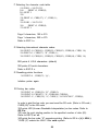
3. How to write program
3-1. Printing on the roll paper
NOTE: Omit step and if the drawer kick-out connector is covered (the
drawer kick-out function is not available).
À For all programs, always first open device RS-232C.
100 OPEN “COMl: N81NN” AS #l
Á Initialize the TM-L60
110 PRINT #l, CHR$(27); “@“;
“PRINT #1", is the order that sends data and commands through the device.
This device is opened in step À .
“CHR$ (27)” is the ESC code.
In order to execute ESC @ (Initialize the printer) send “@” following the ESC
code. Always write “," at the end of the commands or BASIC will send a CR
and LF code.
54
 Send Print Data
120 PRINT #1, “ABCDEF”; CHR$( 10);
Always send a LF code (CHR$ (10)) after print data. To execute printing, send
a LF code or ensure the line is filled.
à Selecting Character Font B
130 PRINT #1, CHR$(27); "!“; CHR$( 1);
140 PRINT #l , “ABCDEF”; CHR$( 10);
The number code that follows “!" alters the font, and also the mode for
character size. Therefore, the example above sets character Font B in lines
130 and 140; the style of “ABCDEF” is changed to the style of Font B.
Font
code
size
code
size
code
size
code
size
A
CHR$(0) Normal
CHR$(16) Double- CHR$(32) Double- CHR$(48) Quadwidth
ruple
height
B
CHR$(1) Normal
CHR$(17) Double- CHR$(33) Double- CHR$(49) Quadruple
width
height
Font B and the size are selected until CHR$ (27); “!“; CHR$ (X); is executed
again or initialized.
Ä Selecting character Font A and Double-width
150 PRINT #l , CHR$(27); “!"; CHR$(48);
160 PRINT #l , “ABCDEFGHIJK”; CHR$( 10);
Font A (normal):
42 character per line
Font A (double-width):
21 characters per line
Å Resetting the style to Normal
170 PRINT #l, CHR$(27); “!"; CHR$(0);
180 PRINT #l , “ABCDEFGHIJK”; CHR$( 10);
170 sets Font A to Normal. 180 sets the characters for printing.
55
Æ Selecting the character code table.
190 FOR I = 240 TO 255
PRINT #l, CHR$(I);
200
210 NEXT I
220 ’
230 PRINT #l , CHR$(27); “t”; CHR$( 1);
240 ’
250 FOR I = 240 TO 255
260
PRINT #l, CHR$(I);
270 NEXT I
Page 0 characters, 190 to 210.
Page 1 characters, 250 to 270.
Refer to ESC t n.
Ç Selecting International character codes
280 PRINT #l, CHR$(91); CHR$(92); CHR$(93); CHRS(94); CHR$( 10);
290 PRINT #l , CHR$(27); “R”; CHR$( 1);
300 PRINT #l, CHR$(91); CHR$(92); CHR$(93); CHRS(94); CHR$( 10);
280 prints 4 U.S.A characters. (default)
300 prints 4 French characters.
Refer to ESC R n.
È Resetting printer functions
310 PRINT #l , CHR$(27); “@“;
Initialize printer again.
É Printing bar codes
320 PRINT #1, CHR$(29); “H”; CHR$(2);
330 PRINT #l, CHR$(27); “$“; CHR$(40); CHR$(0);
340 PRINT #l , CHR$(29); “k”; CHR$(2); “012345678901”; CHR$(0);
In order to print the bar code, you must send the GS code. (Refer to GS code.)
CHR$ (29)” is the GS code.
320 prints HRI (Human Readable Interpretation) as bar codes. Refer to
GS H n.
330 sets the print starting position to the specified number of dots (40).
Refer to ESC $ n1 n2.
340 prints the bar code; “K" executes printing. (Refer to GS k n [d] k NUL.)
“CHR$ (2)” selects the JAN 13 Bar code system.
56
The 12 characters, “012345678901” are print data.
A check-digital is added by the printer because 12 characters are sent, and
“012345678901” is printed.
“CHR$ (0)” must always be used as the last command (representing end of
data.)
Using the drawer kick-out
350 PRINT #l, CHR$(27); “P”; CHR$(0); CHR$( 10); CHR$( 100);
The “p” generates a specified pulse; Refer to ESC p m n1 n2.
In line 350, the module terminal of the drawer kick-out outputs a 20 ms pulse
followed by a 200 ms wait.
How to read the status of the drawer kick-out
360 PRINT #l, CHR$(27); “u”; CHR$(0);
370 A$ = INPUT!$(l, #l)
380 IF A$ = CHR$(0) THEN PRINT “DRW: L”
380 IF A$ = CHR$( 1) THEN PRINT “DRW: H”
The “u” command in line 360 transmits the status of the drawer kick-out to
printer. Refer to ESC u n.
370 receives the data from the printer through RS-232C.
380 and 390 display the status of the drawer kick-out on the CRT.
Close RS-232C
400 CLOSE #l
RS-232C must be closed using this command.
57
g
Sample Program onto thermal paper
100 OPEN “COMl : N81 NN” AS #1
110 PRINT #l , CHR$(27); “@ ";
120 PRINT #1, “ABCDEF”; CHR$( 10);
130 PRINT #l, CHR$(27); “!"; CHR$( 1);
140 PRINT #l, “ABCDEF”; CHR$( 10);
150 PRINT #l, CHRS(27), “!“; CHR$(48);
160 PRINT #l, “ABCDEFGHIJK”; CHR$( 10);
170 PRINT #l, CHR$(27); “!“; CHR$(0);
180 PRINT #l, “ABCDEFGHIJK”; CHR$( 10);
190 FOR I = 240 TO 255
200
PRINT #l, CHR$( I);
210 NEXT I
220 ’
230 PRINT #l, CHR$(27); “t”; CHR$( 1);
240 ’
250 FOR I 240 TO 255
260
PRINT # 1, CHR$( I);
270 NEXT I
280 PRINT #l, CHR$(91); CHR$(92); CHR$(93); CHR$(94); CHR$( 10);
290 PRINT #l, CHR$(27); “R”; CHR$( 1);
300 PRINT #l, CHR$(91); CHR$(92); CHR$(93); CHR$(94); CHR$( 10);
310 PRINT #l, CHR$(27); “@“;
320 PRINT #l, CHR$(29); “H”; CHR$(2);
330 PRINT #l, CHR$(27); “$“; CHR$(40); CHRS(0);
340 PRINT #l, CHR$(29); “k”; CHR$(2); “01234567890 1”; CHR$(0);
350 PRINT #l, CHR$(27); “p”; CHR$(0); CHR$( 10); CHR$( 100);
360 PRINT #1, CHR$(27); “u”; CHR$(0);
370 PRINT A$ = INPUT$( 1, #l)
380 If A$ = CHR$(0) THEN PRINT “DRW: L”
380 If A$ = CHR$( 1) THEN PRINT “DRW: H”
400 CLOSE #l
58
3-2. Printing on label paper
À Open device RS-232C.
100 OPEN “COM 1: N81NN” AS #l
Á Initialize the printer mechanism.
110 PRINT #1, CHR$(29); “<“;
 Send print mode
120 PRINT #l, “ABCDEF”; CHR$( 10);
à Position label to start printing
130 PRINT#l, CHR$(12);
130 positions the next label printing. To position label to start printing, send
a FF code or GS <.
Ä Print serial number counter
140 PRINT #l, CHR$(29); “CO”; CHR$(3); CHR$(0);
150 PRINT #l, CHR$(29); “Cl “; CHR$( 1); CHR$(0); CHR$( 10); CHR$(0);
CHR$(1); CHR$(1);
160 PRINT #l, CHR$(29); “C2”; CHR$( 1); CHR$(0);
170 FOR I = 1 TO 10
180 PRINT #l, CHR$(29); “c”;
190 PRINT #l, CHR$( 12);
200 NEXT I
In lines 140 to 160, it selects the print mode for the serial number counter.
140 selects print format for the serial number counter. CHR$(3) (value of m)
indicates the number of digits to be printed. CHR$(0) (value of n) specifies
the printing position within the entire range of printed digits. In case n = 0, it
prints with right adjusted.
150 selects counter operation range for the serial number counter. In this
case, it counts up from 1 to 10 by 1.
160 sets the initial value of the counter. It indicates 1.
In line 170 to 190, it executes the serial number counting and to position label
to start printing.
Always send a FF code after print data.
59
Å Print and eject label
210 PRINT #l, “ABCDEF”; CHR$( 10);
220 PRINT #l, CHR$(29); CHR$( 12);
210 prints data, then 220 ejects label. After ejection, an ERROR LED is lit and
waits until the paper feed switch is pressed. When the paper feed switch is
pressed after ejecting label, paper feeding is performed to set the next label
at the starting position for printing.
Æ Close RS-232C
230 CLOSE #l
RS-232C must be closed using this command.
n Sample Program onto thermal label paper
100 OPEN “COMl: N81NN” AS #l
110 PRINT #l, CHR$(29); "<”;
120 PRINT #l, “ABCDEF”; CHR$( 10);
130 PRINT #l, CHR§( 12);
140 PRINT #l, CHR$(29); “CO”; CHR$(3); CHR$(0);
150 PRINT #l, CHR$(29); “C1“; CHR$( 1); CHR$(0); CHR$( 10); CHR$(0);
CHR$( 1); CHR$(1);
160 PRINT #l, CHR$(29); “C2”; CHR$( 1); CHR$(0);
170 FOR I = 1 TO 10
180 PRINT #1, CHR$(29); ”c”;
190 PRINT #l, CHR$(12);
200 NEXT I
210 PRINT #l, “ABCDEF”; CHR$( 10);
220 PRINT #l, CHR$(29); CHR$(12);
230 CLOSE #1
60
APPENDIX
APPENDIX A General Specifications
1. Printing specifications
Printing method:
Thermal line printing
Dot density:
180 dpi
Printing direction:
Uni-directional with friction feed
When the GS FF command is executed printing
is performed in the reverse direction.
Print width:
54 mm, 384-dot positions
Characters per line:
Normal paper:
42 (Font B)
32 (Font A)
Label paper:
40 (Font B)
30 (Font A)
Character spacing:
0.28 mm (Font A)
0.28 mm (Font B)
Programmable by control command.
Printing speed:
Approx. 12 lines/second (1/6 inch feed) (* 1)
Approx. 18 lines/second (1/9 inch feed) (* 1)
Approx. 2.0 inches/second (* 1)
Printing speed may slow down depending on the
data transmission speed and combination of control commands.
Paper feeding speed:
Approx. 2.0 inches/second (* 1)
(Approx. 50.0 mm/second)
Line spacing:
1/6 inch (4.23 mm) default
Programmable by control command.
(Minimum 1/360 inch)
(* 1): These speed values indicate approximate printing and paper feeding
speeds between the beginning and ending of a given label.
2. Characters specifications
Character sets:
Alphanumeric:
95
Enlarged graphics:
128 X 2 pages
International:
32
61
Character structure:
12 x 24 (includes the horizontal 2dot space)
9 x 17 (includes the horizontal 2dot space)
Font A:
Font B:
Font A
Default:
Character size:
1.41 mm (W) X 3.39 mm (H) (Font A)
0.99 mm (W) X 2.40 mm (H) (Font B)
Table A-l. Character Sizes
Standard
Double-height
Double-Width
Quadruple
WXH(mm) CPL WXH (mm) CPL WXH (mm) CPL WXH(mm) CPL
Font A
(12 X 24)
1.41 X 3.39
Font B
0.99 X 2.40
(9 x 17)
32
30
1.41 X6.77
32 2.82 X 3.39 16 2.82 X 6.77 16
30
15
15
42
0.99 X 4.80
42 1.98 X 2.40 21 1.98 X 4.80 21
40
40
20
20
Space between characters is not included.
CPL = Character per line.
NOTE: Concerning CPL in the table above, the upper value is for thermal paper
and the lower for label paper.
3. Near-end detector
Detection method:
Micro switch
Roll paper core diameter:
Specified thermal paper:
Inside diameter:
Outside diameter:
12 mm
18 mm
Specified thermal label paper:
Inside diameter:
12 mm
Outside diameter:
22 mm
Adjustment mechanism:
Adjusting screw
The near-end detection processing is
program table by control command.
Adjustment units:
Approx. 2 mm/scale division
4. Paper
4.1 Thermal paper
Paper type:
Specified thermal paper
Paper thickness:
65 ±5 µm
Form:
Roll paper
62
Paper width:
60 ± mm
Roll size:
Roll diameter
Max. ø83 mm
Taken up paper roll width: 60 ±
mm
Specified paper:
Roll paper model No.:
NTP060-80
(NAKAGAWA MFG. Co., Ltd.)
[Original paper model No.:TFSOKS-E)
(JUJO PAPER CO., LTD)]
Roll paper core:
Inside diameter: 12 mm
Outside diameter: 18 mm
Paper should never be pasted to the paper core.
4.2 Thermal label paper
Paper type:
Specified thermal label paper
Paper thickness:
143 ± 15 µm (total)
Form:
Roil paper
Paper width:
60 ± mm
Roll size:
Roll diameter
Max. ø83 mm
Taken up paper roll width: 60 ±
Specified paper:
mm
Thermal label paper:
NTLO60-80
(NAKAGAWA MFG. Co., Ltd.)
Original paper model No.: HD75 (JUJO
PAPER CO., LTD)
Roll paper core:
Inside diameter:
12 mm
Outside diameter:
22 mm
Paper should never be pasted to the paper core.
NOTES:
l
l
l
l
Make sure that it can not be printed in 1.5 mm line spacing in the lower
area of the label paper. (See 5-2 Printable Area and Label Paper
Conditions)
It is recommended to issue GS FF command to position the cutter to the
base sheet of the label paper in order to cut the label paper easily.
Make sure to issue FF or GS FF command just after sending data per
label paper.
Do not use other than specified paper.
5. Receive buffer
Either 4 K or 45 bytes is selectable by a DIP switch
63
6. Electrical characteristics
Supply voltage:
24 VDC ± 7% (Optional power supply:
Current consumption:
Operating:
PS-130)
Mean:
Approx. 1.3 A
(Print duty: 30%)
Peak:
Approx. 6.0 A
(Print duty: 100%)
Approx.
Stand-by:
7.
100 mA
EMI (by using Epson PS-130)
The cables using a shielded wire are used.
FCC:
Class A
VDE:
Class B
8. Reliability
MCBF:
3.5 million lines (equivalent to 0.5 million l-inch
labels at Font A)
9. Environmental conditions
Temperature
Humidity
Operating:
5 to 40°C
Storage:
-10 to 50°C (except for paper)
Operating:
30 to 85% (non-condensing)
Storage:
30 to 90%
(non-condensing, except for paper)
10. External dimensions and weight
Height:
124 mm
Width:
123 mm
Depth:
201 mm
Weight:
Approx. 0.8 kg
11. Case color
EPSON standard gray
64
APPENDIX B Connectors
1. Connectors
Serial Interface Connector
Drawer Kick-out Connector
Power Supply Connector
2. Interface connectors
See APPENDIX C Interfaces
2
3. Power supply connector
This connector is used to connect an external power source.
1) Pin
assignment:
2) Model: User side:
SHELL
Pin 1:
+24 VDC
Pin 2:
GND
Pin 3:
Unconnected
SHELL:
Connected to the frame ground (FG) at the
printer side.
1
3
Connector:
TCP8927-63-1110
(Hoshiden or equivalent)
Cable:
2-core shielded (AWG22 X 2)
Printer side: TCS7960-53-2010 (Hoshiden or equivalent)
NOTE: Start the external power supply after connecting the external power
supply.
4. Drawer kick-out connector (Modular connector)
1) Pin assignment:
Printer side connector:
User-side plug:
TM5RJ3-66 (HIROSE) or
equivalent
Standard 6-pin modular jack
(R11 Telephone jack)
Table B-l. Drawer Kick-out Connector Pin Assignment
Pin Number Signal Name
1
FG
2
L1 (-)
Sender
Printer
Connected to:
Function
Cash drawer
Frame ground
Cash drawer
Drawer kick-out drive signal
L1.
65
Pin Number Signal Name
Sender
Connected to:
Function
3
SW (+)
Cash drawer
Cash drawer
Connected to the (+) side of
the open/close detection
switch on the cash drawer.
Pulled up through a 10 k Ω
resistor on the printer side.
4
L (+)
Printer
Cash drawer
+24 VDC for drawer kick-out
is supplied.
5
L2 (-)
Printer
Cash drawer
Drawer kick-out drive signal
L2.
6
SW (-)
-----
Cash drawer
Connected to the (-) side
of the open/dose detection
switch on the cash drawer.
Connected to the signal
ground on the printer side.
I
I
2) Drawer kick-out drive signal
This signal outputs the pulses specified by the ESC p command.
The SW (+) state is checked by the host computer using the ESC u
command.
Electrical characteristics:
(a) Signal output current:
Maximum -1 A (510 ms or less)
(b) Power supply output voltage:
24 VDC (typical)
(c) Power supply output current:
Maximum 1 A (510 ms or less)
(d) Output waveform:
Refer to Figure B-l
NOTES: 1. These are not output during printing.
2. Drawer kick-out drive signals L1 and L2 cannot be output at the same
time.
3. The resistance of the drawer kick-out solenoids should be 24 Ω or
more. Otherwise, the overcurrent could damage the solenoids.
4. Be sure to use the power supply (pin 4) of the drawer kick-out
connector for the drawer kick-out solenoid power source.
3) Drawer open/close signal
SW (+) signal level: “LOW = 0 to 0.5 V
“HIGH” = 3 to 5 V
NOTE: Do not connect anything otherthan a solenoid to the drive signal terminal
of the drawer kick-out connector.
66
n1 x 2 ms
n2 x 2 ms
Figure B-1. Drawer Kick-out Drive Signal
User side
Printer side
Figure B-2. Drawer Kick-out Signal Interface Circuit
NOTES: The circuit on the user side should be designed so that the drawer
drive duty is as shown below.
ON time
≤ 0.2
ON time + OFF time
l
l
The waveform shown in Figure B-l is output at Point A in Figure B-2
(n1 (ON time) and n2 (OFF time) depend on the ESC p command.)
APPENDIX C Interfaces
1. Specifications (RS-232C compatible)
Data transmission:
Serial
Synchronization:
Asynchronous
Handshaking:
DTR/DSR or XON/XOFF control
Signal level:
MARK = -3 to -15 V:
Logic “1”
SPACE = +3 to + 15 V:
Logic “0”
Baud rates:
1200,4800,9600,19200 bps
Bit length:
8 bits
Parity:
Invalid, even, odd
Stop bits:
1 bit or more
Connector:
D-SUB 25 pin connector
67
2. Interface connector terminal assignments and signal functions
Function
Pin Number Signal Name Signal Direction
-
I
Frame ground
1
FG
2
TXD
output
Transmit data
3
RXD
Input
Receive data
6
DSR
Data set ready
7
GND
Input
-
20
DTR
output
Data terminal ready
Signal GND
3. Serial interface timing
a) Receive data
Either DTR/DSR or XON/XOFF control is selectable. Changes in DTR signal
and XON/XOFF transmission are as follows:
[DTR MARK]
l
l
l
l
l
l
l
[DTR SPACE]
l
l
[XON Transmission]
[XOFF Transmission]
l
l
The period from when the power is turned on to when
the printer first becomes ready to receive data.
In an error state.
When the remaining space in the receive buffer be
comes 10 bytes.
When feeding paper with the paper feed switch.
In paper feed switch waiting state with <GS FF>
command.
In paper feed switch waiting state during macro execution.
When printing down-loaded bit image with <GS />.
When the printer first becomes ready to receive data
after power-on.
When the remaining space in the receive buffer be
comes 20 bytes.
When DTR becomes SPACE.
When DTR becomes MARK.
b) Transmit data (Status information transmission)
When DTR/DSR control is selected, data is transmitted after confirming that
DSR is SPACE. When DTR/DSR control is not selected, data is transmitted
regardless of the DSR state.
68
International character set
71
APPENDIX E Command Summary
Name
Command
Reference Page
HT
Horizontal tab
26
LF
Print and line feed
27
FF
Print and position label to start printing
27
ESC SP
Set character right-side spacing
27
ESC
Set print mode
27
ESC $
Set absolute position
28
ESC %
Select/cancel user-defined character set
29
ESC &
Define user-defined characters
29
ESC *
Set bit image mode
30
ESC 2
Set 1/6 inch line spacing
32
ESC 3
Set line spacing using minimum units
32
ESC =
Select device
32
Initialize printer
33
ESC @
ESC D
Set horizontal tab positions
33
ESC E
Select emphasized mode
34
ESC G
Select double-strike mode
35
ESC J
Print and feed paper using minimum units
35
ESC R
Select international character set
36
ESC V
Set/cancel 90° cw rotated characters
36
ESC ¥
Set relative position
37
ESC -
Turn underline mode on/off
37
ESC a
Align positions
37
ESC c 4
Select paper detectors to stop printing
38
ESC c 5
Enable/disable panel switches
39
ESC d
Print and feed paper n lines
39
ESC p
Generate pulse
39
Command
ESC t
Name
I Select character code table
Reference Page
40
ESC u
Transmit peripheral device status
40
ESC v
Transmit printer status
41
ESC {
Set/cancel upside-down character printing
42
GS FF
Print and eject label
43
GS*
Define down-loaded bit image
43
GS /
Print down-loaded bit image
44
GS :
Set starting/ending of macro definition
45
GS<
Initialize printer mechanism
45
Adjust label paper position to start printing
GS C 0
Select counter print mode
GSCl
Select count mode (A)
GS C2
GSC;
Set counter
46
48
49
Select count mode (B)
Select printing position of HRI characters
Print counter
50
GSf
Select font for HRI characters
51
GSh
Select height of bar code
51
GSk
Print bar code
52
GSw
Select horizontal size (magnification) of bar code
52
GS”
Execute macro
53
73