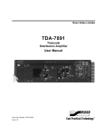
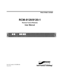
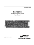
1
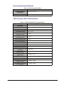
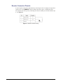
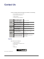
Ross Video Limited
TES3 and TES5
Multi-Standard VBI Processors
Hardware User Manual
TES3 and TES5 • Multi-Standard VBI Processors Hardware User Manual
•
Ross Part Number: TES3DR-004A-02
•
Release Date: September 29, 2010. Printed in Canada.
The information contained in this manual is subject to change without notice or obligation.
Copyright
© 2010 Ross Video Limited. All rights reserved.
Contents of this publication may not be reproduced in any form without the written permission of
Ross Video Limited. Reproduction or reverse engineering of copyrighted software is prohibited.
Patents
This product is protected by the following US Patents: 4,205,346; 5,115,314; 5,280,346;
5,561,404; 7,034,886; 7,508,455. This product is protected by the following Canadian Patents:
2039277; 1237518; 1127289. Other patents pending.
Notice
The material in this manual is furnished for informational use only. It is subject to change without
notice and should not be construed as commitment by Ross Video Limited. Ross Video Limited
assumes no responsibility or liability for errors or inaccuracies that may appear in this manual.
Trademarks
•
is a registered trademark of Ross Video Limited.
•
Ross, ROSS, ROSS are registered trademarks of Ross Video Limited.
•
openGear® is a registered trademark of Ross Video Limited.
•
DashBoard Control System™ is a trademark of Ross Video Limited.
•
All other product names and any registered and unregistered trademarks mentioned in
this guide are used for identification purposes only and remain the exclusive property of
their respective owners.
®
Information to User
The following warning is provided in compliance with the regulations of the United States
Federal Communications Commission (FCC):
“This equipment has been tested and found to comply with the limits for a Class A digital device,
pursuant to Part 15 of the FCC Rules. These limits are designed to provide reasonable protection
against harmful interference when the equipment operates in a commercial environment. This
equipment generates, uses and can radiate radio frequency energy and, if not installed and used in
accordance with the instruction manual, may cause harmful interference in which case the user
will be required to correct the interference at his own expense.
Any changes or modifications not expressly approved by Ross Video could void the user's
authority to operate the equipment.”
Environmental Information
The equipment that you purchased required the extraction and use of natural
resources for its production. It may contain hazardous substances that could
impact health and the environment.
To avoid the potential release of those substances into the environment and to diminish the need
for the extraction of natural resources, Ross Video encourages you to use the appropriate
take-back systems. These systems will reuse or recycle most of the materials from your
end-of-life equipment in an environmentally friendly and health conscious manner.
The crossed-out wheeled bin symbol invites you to use these systems.
If you need more information on the collection, reuse, and recycling systems, please contact your
local or regional waste administration. You can also contact Ross Video for more information on
the environmental performances of our products.
Contents
Introduction
1
Overview.............................................................................................................................. 1-2
Features.................................................................................................................. 1-2
Hardware Overview
2
Before You Begin ................................................................................................................ 2-2
Static Discharge..................................................................................................... 2-2
Unpacking.............................................................................................................. 2-2
Front Panel ........................................................................................................................... 2-3
Rear Panel ............................................................................................................................ 2-4
Installation
3
Mounting the TES3 and TES5 in a Rack............................................................................. 3-2
Before You Begin.................................................................................................. 3-2
Installing the TES3 and TES5 in the Rack............................................................ 3-2
Troubleshooting
4
Troubleshooting ................................................................................................................... 4-2
Replacing a Fuse.................................................................................................... 4-2
Fails to Start........................................................................................................... 4-2
Stays in Bypass...................................................................................................... 4-2
Cannot Decode Data Encoded by the TES3 and TES5......................................... 4-3
Other Operating Difficulties.................................................................................. 4-3
Specifications
5
Technical Specifications ...................................................................................................... 5-2
Electrical Specifications ........................................................................................ 5-2
AC Power Specifications....................................................................................... 5-2
Mechanical Specifications..................................................................................... 5-2
Environmental Specifications................................................................................ 5-3
TES3 Program Video Specifications..................................................................... 5-3
TES5 Program Video Specifications..................................................................... 5-4
Cabling Information............................................................................................................. 5-5
Serial Port .............................................................................................................. 5-5
Remote Connector Pinouts .................................................................................... 5-6
TES3 and TES5 Hardware User Manual (Iss. 02)
Contents • i
ii • Contents
TES3 and TES5 Hardware User Manual (Iss. 02)
Introduction
In This Chapter
This chapter contains the following sections:
•
Overview
A Word of Thanks
Congratulations on choosing the TES3 and TES5 Multi-standard VBI Processors. Your TES3 and
TES5 are part the Ross Terminal Equipment family of products, backed by Ross Video’s
experience in engineering and design expertise since 1974.
You will be pleased at how easily your new TES3 and TES5 fits into your overall working
environment. Equally pleasing is the product quality, reliability and functionality. Thank you for
joining the group of worldwide satisfied Ross Video customers!
Should you have a question pertaining to the installation or operation of your TES3 and TES5,
please contact us at the numbers listed on the back cover of this manual. Our technical support
staff is always available for consultation, training, or service.
TES3 and TES5 Hardware User Manual (Iss. 02)
Introduction • 1–1
Overview
This manual is a hardware reference for two new models in Ross Video's established family of
TV data encoders. The TES3 and TES5 models described in this manual comply with the
Restrictions on Hazardous Substances (RoHS) of the European Union. In all respects, they are
fully compatible with Ross Video’s existing TES3 and TES5 VBI encoders. They offer both
modem and LAN interfaces in a compact 1 rack-unit enclosure, while retaining exactly the same
programming interface as the earlier TES3 and TES5 products.
The TES3 is a broadcast-quality VBI encoder and decoder unit for analog video. It can insert data
in various formats into a program video feed. As well it can decode CEA-608 captioning from
both the program input and an auxiliary analog video input.
The TES5 performs exactly the same functions as the TES3, except that its program video input
and output are serial digital (SMPTE 259) instead of analog video.
Features
The main features of the TES3/TES5 are as follows
1–2 • Introduction
•
Encodes multiple VBI formats simultaneously, including CEA-608 captioning, CEA-516
(NABTS) and WST. This allows a single TES3 or TES5 to perform the functions of
several encoders, minimizing system cost and maximizing reliability.
•
The CEA-608 decoder on the program video input allows captioning and XDS (Extended
Data Services) to be added to incoming CEA-608 data.
•
The CEA-608 decoder on the auxiliary video input permits bridging of captioning
between two video signals (for example, between 525 and 625-line signals).
•
33.6 kbps modem
•
10/100-baseT Ethernet LAN interface
•
3 serial RS232 ports
•
Broadcast-quality video processing
•
Compatible with 525 and 625-line video signals
•
“Master inserter” or “VBI sidechain” function allows the active portion of selected VBI
lines from a synchronous video signal on the auxiliary video input to be inserted into the
program output.
•
Program video bypass if power supply fails.
•
Front panel video bypass switch.
•
On loss of program video, the TES3 or TES5 normally goes into bypass. The user can
optionally set it to instead route the auxiliary input to the program output on loss of
program input.
•
Remote control connector can be used to put the unit into bypass and to indicate bypass
status.
TES3 and TES5 Hardware User Manual (Iss. 02)
Hardware Overview
In This Chapter
This chapter provides an overview of the hardware.
The following topics are discussed:
•
Before You Begin
•
Front Panel
•
Rear Panel
TES3 and TES5 Hardware User Manual (Iss. 02)
Hardware Overview • 2–1
Before You Begin
Before proceeding with the instructions in this manual, review the following notes.
Static Discharge
Throughout this chapter, please heed the following cautionary note:
ESD Susceptibility — Static discharge can cause serious damage to sensitive
semiconductor devices. Avoid handling circuit boards in high static environments such as
carpeted areas and when synthetic fiber clothing is worn. Always exercise proper grounding
precautions when working on circuit boards and related equipment.
Unpacking
Unpack each TES3 and TES5 you received from the shipping container and ensure that all items
are included. If any items are missing or damaged, contact your sales representative or Ross
Video directly.
2–2 • Hardware Overview
TES3 and TES5 Hardware User Manual (Iss. 02)
Front Panel
Figure 2.1 shows the front panel controls and indicators on the TES3 and TES5. The TES3 is
used for illustration, but the controls and indicators are identical on the TES5.
Figure 2.1 TES3 Front Panel Controls and Indicators
1. STATUS
This indicator can be either red or green. It is red when the unit is first powered on and then turns
green approximately 30 seconds later. If it does not, this may indicate that there is a problem; see
Chapter 4, Troubleshooting. After power-up, application software controls the color of the
indicator; for example, the color of the indicator changes to red when the unit is writing to its
flash memory. It is thus normal for this indicator to turn red briefly and then return to green, after
setup changes.
2. Ports A, B, C
These indicators are green when serial data is being received or sent using the corresponding
serial port A, B or C.
3. Auxiliary Channel Indicators
4.
•
AUX VIDEO: This indicator is green when video is present on the cable attached to the
AUXILIARY BNC connector on the rear panel.
•
AUX DECODE: This indicator is green when CEA-608 data is received in the auxiliary
video input.
MODEM and LAN Indicators
These indicators show activity on the MODEM and LAN ports.
5. Program Channel Indicators
•
PGM VIDEO: This indicator is green when video is present on the cable attached to the
Program BNC connector on the rear panel.
•
PGM DECODE: This indicator is green when CEA-608 data is received in the Program
video feed.
•
INSERT: This indicator is green when the unit is inserting any data into the PROGRAM
video feed.
6. BYPASS Indicator
This indicator is red when the PROGRAM video input is in the bypass state. This can be caused
by either the front panel switch or the rear panel REMOTE connector. It is also normally red if
there is no video signal present on the PROGRAM VIDEO IN BNC.
7. BYPASS Switch
When this push-button is approximately flush with the front panel (ACTIVE), the PROGRAM
video feed passes through the encoding circuitry and data insertion can occur. When the
push-button protrudes from the front panel (BYPASS), the PROGRAM video is connected from
the PROGRAM IN BNC directly to the PROGRAM OUT BNC.
TES3 and TES5 Hardware User Manual (Iss. 02)
Hardware Overview • 2–3
Rear Panel
Figure 2 shows the rear panel controls and connectors on the TES3 or TES5. The TES3 is used
for illustration; the control and connectors are identical on the TES5, except that its Program
Video Input and Output are SDI (SMPTE 259).
Figure 2.2 TES3 Rear Panel Connections and Controls
1. Power Switch
2. Fuse Holder
Behind this panel is an AC fuse.
3. Power cord connection
This jack accepts a power cord supplying 120/220 volt, 50/60 Hz power to the unit.
4. AUXILIARY VIDEO IN
This BNC provides the auxiliary video signal to the unit. This is analog composite video on both
the TES3 and TES5.
5. PROGRAM VIDEO OUT
This BNC provides the local program video signal output containing the inserted VBI data. It is
the same type as the PROGRAM VIDEO IN jack.
6. PROGRAM VIDEO IN
This BNC provides the program video input signal to the unit. This is analog composite video for
the TES3, and SDI (259) for the TES5.
7. LOAD
This push-button switch is located behind a small hole in the rear panel and is accessible using a
pointed object, such as a pencil. The software reads this switch during power up and, if the switch
is pressed, jumps to a secondary program instead of the normal application software. This switch
is intended for use in loading new software into the unit.
8. REMOTE
This connector allows remote control of the bypass switch and provides the signals necessary to
drive a remote bypass LED.
9. MODEM
This RJ-11 connector is used to connect the internal modem to a telephone line.
10. PORTS A, B, C
These 9 pin male D connectors can be used to connect the TES3 or TES5 to serial RS232 devices.
11. PARALLEL
This 9 pin female D connector is intended for general-purpose input or output connections.
12. LAN
This RJ-45 connector is used to connect the internal LAN adaptor to an Ethernet network.
2–4 • Hardware Overview
TES3 and TES5 Hardware User Manual (Iss. 02)
Installation
In This Chapter
This chapter describes how to mount the TES3 or TES5 in the rack and provides a general
overview of how to install the TES3 and TES5.
The following topics are discussed:
•
Mounting the TES3 and TES5 in a Rack
TES3 and TES5 Hardware User Manual (Iss. 02)
Installation • 3–1
Mounting the TES3 and TES5 in a Rack
This section describes how to mount the TES3 and TES5 in the rack. In using these instructions,
consult Figure 3.1. Note that the TES3 and TES5 should be attached to both the front and rear of
the rack; because of the weight of the potentially large number of cables connected to the rear of
the TES3 and TES5, rear rack mounting is strongly advised.
Before You Begin
These instructions can be used for racks having a total depth from the front to the rear rails in the
range 24-30.25” (61-77 cm).
•
For racks that are shallower than 24", a modified procedure is described in step 2.
•
For racks deeper than 30.25", use a mounting shelf.
Figure 3.1 TES3 and TES5 Rear View — Rack-mounting Detail
Installing the TES3 and TES5 in the Rack
Use the following procedure to install the TES3 and TES5 in the rack:
1. Attach the rear TES brackets (41-10543-01) to both sides of the chassis using the
mounting holes near the rear of the TES. Use the #8-32 flat-head screws, and insert them
through the countersunk holes in the bracket into the mounting holes on the TES. See
item 3 in Figure 3.1. Install four nut clips to the front of the rack, and attach the TES
front panel to these clips, using four 3/4” #10-32 screws.
2. If your rack is shallower than 24" (61 cm), and it has side-mounting rails, use the
following procedure. Otherwise, proceed to step 3.
•
Skip steps 3 through 5.
•
Instead, mount the rear nut clips to the rear side rails and attach the TES brackets
directly to these side rails, using 3/4” #10-32 screws through the slots in the
brackets.
•
Proceed to step 6.
3. Install four nut clips to the rear of the rack at the same height as those used to mount the
front of the TES.
3–2 • Installation
TES3 and TES5 Hardware User Manual (Iss. 02)
4. Attach the two rear rack brackets (41-10544-01) to the nut clips installed in the
preceding step, using two 3/4” #10-32 screws for each bracket. See item 4 in Figure
3.1. Before tightening the screws, ensure that these brackets contact the inner side of the
brackets mounted to the TES; that is, they should be closer to the center of the rack than
the ones on the TES. The slots in these brackets should also be approximately aligned
with the screw holes in the TES brackets.
5. Install two 3/8” #10 screws through the slots in each rear bracket into the captive nuts
near the rear end of the TES brackets. See item 5 in Figure 4.
6. Plug the power cord into the receptacle on the rear of the TES.
7. Insert a tie-wrap through the strain relief bridge on the rack bracket near the TES power
entry module; see item 6 in Figure 3.1. Pass the tie-wrap around the power cord and
tighten it to prevent the power cord from being inadvertently pulled out of the TES.
8. Insert the TEST’s power plug into a 110 or 220 VAC outlet. The use of conditioned
power from an uninterrupted power source (UPS) is strongly recommended, in order to
ensure that the processing of the video and VBI data is not disturbed by power outages.
9. Most uses of the TES require connecting a video input to the PROGRAM IN jack, and
connecting the PROGRAM OUT jack to another piece of equipment that uses the
video. It is essential to always use high-quality coaxial cable with 75 ohm BNC plugs for
these connections. In particular, SDI video connections require digital video cable such
as Belden type 8281.
10. Most applications also require connection of one or more data ports (RS232, LAN or
modem). Please note the following points related to the RS-232 ports A, B and C:
•
When connecting to another device such as a PC that is wired as Data Terminal
Equipment (DTE), you need to use a null modem cable such as the one supplied
with the TES. Additional cables can be purchased by contacting your Ross Video
sales representative. The part number is CBL-SER-ENC or 91-09497-01.
Alternatively, you can build your own cable or find an equivalent one available
from a cable supplier, using the wiring table provided in section 2.3.6.
•
When connecting to a device that is wired as Data Communications Equipment
(DCE), such as a modem, you need to use a “straight-through” 9-pin cable instead
of the null-modem. This cable is not supplied with the TES, but is readily available
from data cable suppliers.
•
Although you will use PORT A for your initial setup, you do not have to dedicate it
to this purpose alone. If you enable setup to occur through the LAN, PORT A is
then available for data transmission. Also, PORT A can be used alternately for
setup and data transmission, provided your application allows the data transmission
to be suspended whenever you need to change the setup.
11. Consult the user manual for the software which was supplied with the unit for further
installation and setup instructions.
TES3 and TES5 Hardware User Manual (Iss. 02)
Installation • 3–3
3–4 • Installation
TES3 and TES5 Hardware User Manual (Iss. 02)
Troubleshooting
In This Chapter
This chapter contains the following sections:
•
Troubleshooting
TES3 and TES5 Hardware User Manual (Iss. 02)
Troubleshooting • 4–1
Troubleshooting
Other error conditions not outlined in this section may depend on the software modules loaded
into the TES3 and TES5, and on the application software that provides the data for encoding.
Please refer to the manuals for these software packages for additional troubleshooting assistance.
Replacing a Fuse
The AC power to the TES3 and TES5 is protected by a 1-ampere fuse; this is located behind a
small cover on the rear-panel power entry module. If the power cord is attached to the TES3 and
TES5 and plugged into a live AC outlet, and the power switch is in the ON position, yet none of
the LEDs on the TES3 and TES5's front panel come on, the fuse has probably blown.
In order to change it, use the following procedure:
1. Remove the power cord from the receptacle on the rear of the TES3 and TES5.
2. Insert a small screwdriver or equivalent tool into the small slot at the upper edge of the
fuse holder in the centre of the power entry module. Press downwards and pull slightly
outwards to disengage the upper clip.
3. Repeat the preceding step on the lower clip of the fuse holder.
4. If necessary, repeat steps 2 and 3 to fully release the fuse holder.
5. Carefully pull the fuse holder out of its housing, and be prepared to catch the fuse if it
falls out.
6. Replace the live (upper) fuse by the spare one in the lower container marked “spare
fuse”.
7. If you have a supply of fuses available, place a new one in the “spare” location.
8. Carefully return the fuse holder to its housing, and press lightly until it clicks into place.
Note that it is keyed so that you cannot insert it incorrectly.
9. Plug the power cord back into the TES3 and TES5's receptacle, and turn the power
switch to the on (up) position.
The two fuses supplied with the TES3 and TES5 are Littelfuse part number 218001.
Fails to Start
The STATUS LED on the front panel is red when the unit is first powered on. After initialization,
the LED should turn green.
If the indicator is red for more than 1 minute after power-on, turn the unit off for several seconds
and then back on. If the indicator is still red after 1 minute, contact Ross Video Technical Support.
Note that if this LED occasionally switches between red and green during operation, this does not
necessarily indicate a problem.
Stays in Bypass
The TES3 and TES5 requires the following conditions to switch from bypass to active:
4–2 • Troubleshooting
•
power on;
•
front-panel bypass switch pressed in;
•
bypass switch contacts on REMOTE connector open;
TES3 and TES5 Hardware User Manual (Iss. 02)
•
VIDEO IN present.
If the bypass LED stays on after the TES has fully powered up, even though all the above
conditions are met, please check that the video input is the correct type (analog for the TES3,
259M SDI for the TES5). If so, there may be an internal fault in the TES. Contact Ross Technical
Support.
Cannot Decode Data Encoded by the TES3 and TES5
If the TES3 and TES5 is out of bypass, and it has been set up to encode VBI services, these
services should be injected into the designated lines of the Video Out signal. If you believe that
they are not, please check the following:
•
The PGM VIDEO and INSERT LEDs should both be illuminated green. The INSERT
LED may be blinking if the data is not continuous.
•
If PGM VIDEO is green and INSERT is off, no data is being provided for insertion. Use
the setup software to check the settings. Check that the data port that should be providing
the data (e.g. Port A-C, LAN or MODEM) is connected and that the data source is
operating.
•
If using one of the RS232 connections Port A-C, check that the baud rate is set properly
and that the cable is the proper null modem type, as defined in section 2.3.6. If the LED
for the specified port is on or flashing green, data is being received and there is probably
an incorrect setting in the TES. If the LED for the specified port is solidly off, the
problem is with the data source or the cable.
•
If using the LAN connection, check that the LAN LED is on. Check that the LAN
settings of the TES (IP address etc.) match those used by the application that is sending
the data. Make sure that the sending application is running.
•
If both PGM VIDEO and INSERT LEDs are green, encoding is taking place. If you are
unable to decode the data from the expected line downstream, check the following
possibilities. The TES may be setup to encode with a different VBI format, or in a
different line than those expected by the decoding equipment; check the settings. There
may be equipment downstream from the TES that is damaging the inserted data; try
connecting the decoding device directly to the video output of the TES, to check this. If
you have access to a waveform monitor or video analyzer, connect the TES Video Out to
it, to verify the presence and coding of the encoded data.
Other Operating Difficulties
The operation of the TES is strongly dependent on the software that is installed in it. This manual
therefore does not discuss all aspects of operating the TES. If you should experience difficulty in
operating the TES, please refer to the TES3 and TES5 Encoder Software User Manual. For
additional assistance, please contact Ross Technical Support.
TES3 and TES5 Hardware User Manual (Iss. 02)
Troubleshooting • 4–3
4–4 • Troubleshooting
TES3 and TES5 Hardware User Manual (Iss. 02)
Specifications
In This Chapter
This chapter provides the technical specification information for the TES3 and TES5. Note that
technical specifications are subject to change without notice.
The following topics are discussed:
•
Technical Specifications
TES3 and TES5 Hardware User Manual (Iss. 02)
Specifications • 5–1
Technical Specifications
This section provides technical information on the TES3 and TES5.
Electrical Specifications
Table 5.1 TES3 and TES5 Electrical Specifications
Connector
Specification
PORT A
RS232, up to 115.2K bits/sec, see 2.3.6 for pinouts
PORT B
RS232, up to 115.2K bits/sec, see 2.3.6 for pinouts
PORT C
RS232, up to 115.2K bits/sec, see 2.3.6 for pinouts
AUXILIARY VIDEO IN
Analog composite, 1 Vpp into 75 ohms
TES3: Analog composite, 1.0 Vpp, 75 ohms.
PROGRAM VIDEO IN
TES5: SMPTE 259 component SDI, 800 mv, 270
Mbit/sec, 75 ohms
TES3: Analog composite, 1.0 Vpp, 75 ohms.
PROGRAM VIDEO OUT
MODEM
LAN
REMOTE
PARALLEL
TES5: SMPTE 259 component SDI, 800 mv, 270
Mbit/sec, 75 ohms
Analog telephone line
Ethernet connection, 10/100-baseT
TTL in and out, see Table 2 8 for pinouts
TTL in and out. Not presently used.
AC Power Specifications
Table 5.2 AC Power Specifications
Category
Voltage
Frequency
Current
Fuse
Specification
90 to 250 VAC
47 to 63 Hz
0.2 A
1A
Mechanical Specifications
Table 5.3 Mechanical Specifications
Category
5–2 • Specifications
Dimension
Width
19" (48.3 cm)
Height
1.72" (4.4 cm)
Depth
12.2" (31cm)
Weight
6.6 lbs (3.0 kg)
TES3 and TES5 Hardware User Manual (Iss. 02)
Environmental Specifications
Table 5.4 AC Power Specifications
Category
Operating Ambient
Temperature
Relative Humidity
Specification
0-40° C (32-104° F)
10-90% non-condensing
TES3 Program Video Specifications
Table 5.5 TES3 and TES5 Electrical Specifications
Category
Specification
Video Gain
100% ± 0.2%
2T pulse/bar ratio
100% ± 0.2%
1T pulse/bar ratio
100% ± 0.2%
0.5T pulse/bar ratio
100% ± 0.2%
Chroma/Luma Gain
inequality (12.5T)
< 0.2%
Chroma/Luma Delay
inequality (12.5T)
< 10 ns
Field square-wave tilt
< 0.2%
Line Time Distortion
< 0.2%
Luma non-linearity
< 0.2%
Blanking Level (DC bounce) 0V ±10 mV
Clamp time (DC bounce)
< 4 ms
Spurious (e.g. switching
transients)
< 10 mVp-p
Random noise
Frequency Response
(multi-burst)
< 60 dB
0-5 MHz: < 0.2%
Differential Gain
< 0.2%
Differential Phase
< 0.2°
Input Return Loss Power
On (multi-burst)
> 46 dB to 5 MHz
Input Return Loss Power
Off or Bypass
> 40 dB to 5 MHz
TES3 and TES5 Hardware User Manual (Iss. 02)
Specifications • 5–3
TES5 Program Video Specifications
Table 5.6 TES5 Program Video Specifications
Category
Input cable equalization
(pathological signal)
Output jitter
Specification
> 300 m of type 8281 cable
< 0.08 UI
Input return loss (active)
> 15 dB to 270 MHz
Input return loss (bypass)
> 13 dB to 270 MHz
5–4 • Specifications
TES3 and TES5 Hardware User Manual (Iss. 02)
Cabling Information
This section provides additional cabling information for the TES3 and TES5.
Serial Port
The pin connections for PORT A, PORT B and PORT C are shown in the following table. These
D9 jacks are the same type commonly found on PCs.
Table 5.7 D9 Pin Connections
Pin
Signal
Direction
1
DCD
Input to TES
2
RXD
Input to TES
3
TXD
Output to TES
4
DTR
Output to TES
5
GND
Ground reference
6
DSR
Input to TES
7
RTS
Output from TES
8
CTS
Input to TES
9
RI
Not connected
The following table shows the wiring of the 91-09497-01 null modem cable supplied with the
TES3 and TES5. This table can be used to construct a cable to connect PORT A, PORTB or
PORTC to a COM port on a PC or other such equipment. This shows, for example, that the DTR
signal on pin 4 of the TE9 drives pins1 (DCD) and 6 (DSR) on the PC.
Table 5.8 Connection from TES3 and TES5 to a PC
TES3 and TES5 Connector
PC D9 Connector
Pin
Name
2
RXD
3
TXD
3
TXD
2
RXD
4
DTR
1
DCD
6
DSR
5
GND
5
GND
1
DCD
6
DSR
4
DTR
7
RTS
8
CTS
8
CTS
7
RTS
9
No connection
9
No Connection
TES3 and TES5 Hardware User Manual (Iss. 02)
Pin
Name
Specifications • 5–5
Remote Connector Pinouts
A remote bypass switch can be implemented by connecting one side of a single pole single throw
switch to pin 1 of the REMOTE connector and the other side to pin 2. An indication of the
active/bypass state can be given by connecting the anode of a LED to pin 3 and the cathode to pin
2. See Figure 5.1.
Figure 5.1 Remote Connector Wiring
5–6 • Specifications
TES3 and TES5 Hardware User Manual (Iss. 02)
Notes:
Contact Us
Contact our friendly and professional support representatives for the following:
•
Name and address of your local dealer
•
Product information and pricing
•
Technical support
•
Upcoming trade show information
PHONE
General Business Office
and Technical Support
613 • 652 • 4886
After Hours Emergency
613 • 349 • 0006
Fax
613 • 652 • 4425
General Information
[email protected]
Technical Support
[email protected]
Ross Video Limited
8 John Street,
Iroquois, Ontario, Canada
K0E 1K0
Ross Video Incorporated
P.O. Box 880,
Ogdensburg, New York, USA
13669-0880
E-MAIL
POSTAL
SERVICE
Visit Us
Please visit us at our website for:
•
Company information
•
Related products and full product lines
•
On-line catalog
•
News
•
Testimonials
Ross Part Number: TES3DR-004A-02