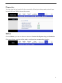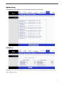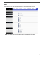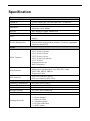
1
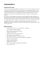
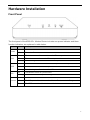
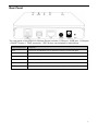
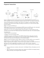
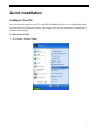
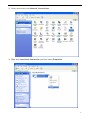
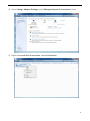
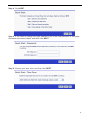
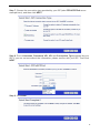
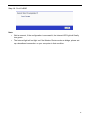
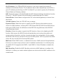
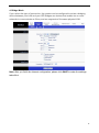
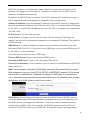
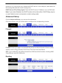
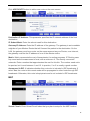
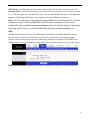
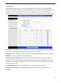
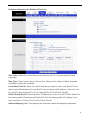
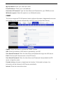
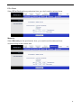
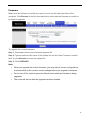
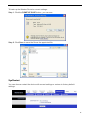
CAR2-701U Combo Port ADSL2/2+ Modem Router User Manual V1.0 © 2011 * Note: Before using your product, please read this manual instruction carefully CONTENTS INTRODUCTION .......................................................................................................................................... 1 Product Overview .......................................................................................... 1 Main Features ............................................................................................... 1 HARDWARE INSTALLATION ................................................................................................................. 2 Front Panel .................................................................................................... 2 Rear Panel..................................................................................................... 3 Physical Connection ...................................................................................... 4 QUICK INSTALLATION............................................................................................................................. 5 Configure Your PC......................................................................................... 5 Install Your Modem Router .......................................................................... 13 SOFTWARE CONFIGURATION .......................................................................................................... 17 Quick Start ................................................................................................... 17 Interface Setup ............................................................................................ 17 Internet ........................................................................................................................................................... 18 LAN ................................................................................................................................................................. 25 Advanced Setup .......................................................................................... 27 Firewall ........................................................................................................................................................... 27 Routing ........................................................................................................................................................... 27 NAT ................................................................................................................................................................. 28 QoS ................................................................................................................................................................ 32 VLAN .............................................................................................................................................................. 34 ADSL .............................................................................................................................................................. 36 Access Management ................................................................................... 36 ACL ................................................................................................................................................................. 37 Filter................................................................................................................................................................ 38 SNMP ............................................................................................................................................................. 39 UPnP .............................................................................................................................................................. 40 DDNS ............................................................................................................................................................. 40 CWMP ............................................................................................................................................................ 41 Maintenance ................................................................................................ 42 i Administration ............................................................................................................................................... 42 Time Zone...................................................................................................................................................... 43 Firmware ........................................................................................................................................................ 45 SysRestart ..................................................................................................................................................... 46 Diagnostics .................................................................................................................................................... 47 Status .......................................................................................................... 47 Device Info .................................................................................................................................................... 48 System Log ................................................................................................................................................... 49 Statistics ........................................................................................................................................................ 49 Help ............................................................................................................. 50 SPECIFICATION ....................................................................................................................................... 51 CERTIFICATION ....................................................................................................................................... 52 CE Mark Warning ........................................................................................ 52 ii Introduction Product Overview Thank you for choosing this ADSL2/2+ Modem Router. This product is designed to provide a simple and cost-effective ADSL internet connection for a private Ethernet network. It is connected to network devices via standard Ethernet ports. The ADSL connection is made using ordinary telephone line with standard connectors. Multiple workstations can be networked to internet using a single Digital Subscriber Line (DSL) and single global IP address. Quick Start of the Web based Setup Wizard is supplied and friendly help messages are provided for the configuration. Network and Router management is done through the Web based Setup Wizard which can be accessed through local Ethernet using any web browser. This ADSL Modem Router supports full-rate ADSL2/2+ connectivity conforming to the ITU and ANSI specifications. In addition to the basic DMT physical layer functions, the ADSL2/2+ PHY support dual latency ADSL2/2+ framing (fast and interleaved) and the I.432 ATM Physical Layer. Main Features Provides 1 RJ11 DSL Port, 1 RJ45 LAN port, 1 USB port Up to 24Mbps downstream speed Reach of 6.5km from your ISP DSLAM Supports Build-in PPPoE DHCP Server/Relay/Client, UPnP, DDNS NAT, Static routing ,and DMZ host QoS prioritization based on IP type of service Easy Setup Assistant provides quick & hassle free installation Supports web management Supports firmware upgrade Supports flow statistics Built-in firewall supporting IP/Mac address filtering Built-in DHCP server 1 Hardware Installation Front Panel The front panel of the ADSL2/2+ Modem Router includes one power indicator and three function indicators, as explained in table below: LED Power LAN Status Description On Power is on Off Power is off On There is a successful connection on the Ethernet port Off There is no connection on the Ethernet port or the connection is abnormal Blinking Data is being transferred over the Ethernet port USB On There is a successful connection on USB port but no activity Off There is no connection on USB port or the connection is abnormal Blinking Data is being transferred over the USB connection DSL Internet On The Modem Router is synchronized Blinking The Modem Router is synchronizing Green A successful PPP connection has been built Off The DSL port is linked down or the Modem Router works in Bridge mode Red The PPP connection failed to be established 2 Rear Panel The rear panel of the ADSL2/2+ Modem Router includes 1 DSL port, 1USB port, 1 LAN port, 1 ON/OFF button, 1 PWR connector, 1 RST button, as explained in table below: Interface/Button Function DSL Connect to the Modem port of splitter or directly to the wall jack USB Connect to your USB device LAN Connect to your network device ON/OFF Turn on/off the power of ADSL2/2+ Modem Router PWR Connect with a power adapter RST Restore to factory default settings by pressing and holding for 5 seconds 3 Physical Connection Before installing the device, please make sure your broadband service provided by your ISP is available. If there is any problem, please contact your ISP. You need to connect the device to the phone jack, the power outlet, and your computer or network. Before cable connection, turn off the power supply and keep your hands dry. You can follow the steps below to install it. Step 1: Connect the ADSL Line. Method one: Plug one end of the twisted-pair ADSL line into the DSL port on the rear panel of this ADSL Modem Router, and insert the other end into the wall socket. Method two: You can use a separate splitter. External splitter can divide data and voice, and then you can access the Internet and make calls at the same time. The external splitter has three ports: • LINE: Connect to the wall jack. • PHONE: Connect to the phone sets. • MODEM: Connect to the DSL port of this ADSL Modem Router. Plug one end of the twisted-pair ADSL line into the DSL port on the rear panel of this ADSL Modem Router. Connect the other end to the Modem port of the external splitter. Step 2: Connect the Ethernet cable. Attach one end of a network cable to your computer’s Ethernet port or a regular hub/switch port, and the other end to the LAN port. Step 3: Attach the power adapter. Connect the AC power adapter to the PWR connector on the rear of the device and plug in the adapter to a wall outlet or power extension. Step 4: Turn on this ADSL Modem Router and power on the computers and LAN devices. Note: If you currently use a modem, disconnect it, the Modem Router will replace your old modem. After the physical connection please check whether the LEDs of the Modem Router display normally as the diagram below describes. 4 Quick Installation Configure Your PC After you directly connect your PC to this ADSL Modem Router or to a Hub/Switch which has connected to this Modem Router, we suggest you set your computer to obtain the IP address automatically. For Windows XP/2000 1) Click Start > Control Panel. 5 2) Select and double click Network Connections. 3) Right click Local Area Connection and then select Properties. 6 4) Select Internet Protocol (TCP/IP) and click Properties. 5) Select Obtain an IP address automatically and Obtain DNS server address automatically. Then click OK. 7 6) Run the Ping command in the command prompt to verify the network connection. Click Start menu on your desktop, select Run tab, type cmd in the field. 8 7) Then type ping 192.168.1.1, press Enter. If the screen looks like the following, you have succeeded For Windows Vista/7: 1) Click Start>Control Panel. 9 2) Click Network and Internet. 3) Click Network and Sharing Center. 10 4) Go to Change Adapter Settings (win7)/Manage Network Connections (Vista). 5) Right click Local Area Connection, choose Properties. 11 6) Select Internet Protocol Version 4 (TCP/IPv4) and click Properties. 7) Select Obtain an IP address automatically and Obtain DNS server address automatically. Then click OK. Note: After your computer is configured successfully, go to the next section to configure the Modem Router via web. Otherwise, refer to the question 1 in Troubleshooting section to reset the modem. 12 Install Your Modem Router To configure the device, you can run the Web based Setup Wizard. For first-time installation, follow the step-by-step instructions to finish the installation. After the initial configuration is done, you can login to the Web based Setup Wizard to configure do some additional settings. Here we introduce how to set it up via Web based Setup Wizard. Step 1: Open your web browser, in the address bar, type in 192.168.1.1 Step 2: You are prompt to enter the Username/Password (preset as admin/admin) which you can found on the label at the bottom of your router, and then click OK. Step 3: Go to Quick Start tab, and then click RUN WIZARD. 13 Step 4: Click NEXT. Step 5: If you want to change the login password, put in the new password in this page. Otherwise just leave it blank, and then click NEXT. Step 6: Choose your time zone, and then click NEXT. 14 Step 7: Choose the connection type provided by your ISP (take PPPoE/PPPoA as an example here), and then click NEXT. Step 8: Put in Username, Password, VPI, VCI and Connection Type provided by your ISP. If you are not sure about the information, please confirm with your ISP. Then click NEXT. Step 9: Click NEXT. 15 Step 10: Click CLOSE. Note: Wait a moment, if the configuration is successful, the Internet LED light will finally turn green. The Internet light will not light on if the Modem Router works as bridge, please set up a broadband connection on your computer in that condition. 16 Software Configuration This User Manual recommends using the Quick Installation Guide for first-time installation. For advanced users, if you want to know more about this device and make use of its functions adequately, maybe you will get help from this chapter to configure the advanced settings through the Web based Setup Wizard. After your successful login, you can configure and manage the device. There are main menus on the top of the Web based Setup Wizard; submenus will be available after you click one of the main menus. In the center of the Web based Setup Wizard, there are the detailed configurations or status information. To apply any settings you have altered on the page, please click APPLY/SAVE button. Quick Start Please refer to Install Your Modem Router. Interface Setup Choose Interface Setup, you can see two submenus: Internet, LAN. Click any of them, you will be able to configure the corresponding function. 17 Internet ATM VC: ATM settings are used to connect to your ISP. Your ISP provides VPI (Virtual Path Identifier), VCI (Virtual Channel Identifier) settings to you. In this Device, you can totally setup 8 VCs on different encapsulations, if you apply 8 different virtual circuits from your ISP. You need to activate the VC to take effect. For PVCs management, you can use ATM QoS to setup each PVC traffic priority. Virtual Circuit: Select the VC number you want to setup, PVC0~PVC7. Status: If you want to use a designed VC, you should activate it. VPI: Identify the virtual path between endpoints in an ATM network. The valid range is from 0 to 255. Please input the value provided by your ISP. VCI: Identify the virtual channel endpoints in an ATM network. The valid range is from 32 to 65535 (1 to 31 is reserved for well-known protocols). Please input the value provided by your ISP. PVCs Summary: You can view the summary information about the PVCs. QoS: Select the Quality of Service types for this Virtual Circuit, including CBR (Constant Bit Rate), UBR (Unspecified Bit Rate) and VBR (Variable Bit Rate). These QoS types are all controlled by the parameters specified below, including PCR (Peak Cell Rate), SCR (Sustained Cell Rate) and MBS (Maximum Burst Size), please configure them according your needs. 18 Encapsulation: There are four connection types: Dynamic IP Address, Static Address, PPPoA/PPPoE and Bridge Mode. Please choose the designed type that you want to use. After that, you should follow the configuration below to proceed. 1. Dynamic IP Address Select this option if your ISP provides you an IP address automatically. This option is typically used for Cable services. Please enter the Dynamic IP information accordingly. Encapsulation: Select the encapsulation mode for the Dynamic IP Address, you can leave it default. Bridge Interface: Activate the option, and the Router can also work in Bridge mode. NAT: Select this option to Enable/Disable the NAT (Network Address Translation) function for this VC. The NAT function can be activated or deactivated per PVC basis. Default Route: If enable this function, the current PVC will be considered as the default gateway to internet from this device. TCP MTU Option: Enter the TCP MTU as you desire. Dynamic Route: Select this option to specify the RIP (Routing Information protocol) version for WAN interface, including RIP1, RIP2-B and RIP2-M. RIP2-B and RIP2-M are 19 both sent in RIP2 format, the difference is that RIP2-M using Multicast, while RIP2-B using Broadcast format. Direction: Select this option to specify the RIP direction. None is for disabling the RIP function. Both means the ADSL Router will periodically send routing information and accept routing information, and then incorporate them into routing table. IN only means the ADLS router will only accept but will not send RIP packet. OUT only means the ADLS router will only send but will not accept RIP packet. Multicast: Select IGMP version, or disable the function. IGMP (Internet Group Multicast Protocol) is a session-layer protocol used to establish membership in a multicast group. The ADSL ATU-R supports both IGMP v1 and IGMP v2. Select Disabled to disable this function. 20 2.Static IP Address Select this option if your ISP provides static IP information to you. You should set static IP address, IP subnet mask, and gateway address on the screen below. Note: Each IP address entered in the fields must be in the appropriate IP form, which is four IP octets separated by a dot (x.x.x.x), such as 192.168.1.100. The Router will not accept the IP address if it is not in this format. 21 3. PPPoA/PPPoE Select this option if you have a username and password to access internet. This option is typically used for DSL services. Select Dynamic to obtain an IP address automatically for your PPP connection. Select Static to use a static IP address for your PPP connection. Please enter the information accordingly. Service name: This is optional, if you don’t have a service name, leave it blank. Username: Enter your username for your PPPoA/PPPoE connection. Password: Enter your password for your PPPoA/PPPoE connection. Encapsulation: For both PPPoA/PPPoE connection, you need to specify the type of Multiplexing, either LLC or VC -Mux. Bridge Interface: Activate the option, the Router can also work in Bridge mode. Connection: For PPPoA/PPPoE connection, you can select Always on, Connect on-Demand or Connect Manually. Connect on demand is dependent on the traffic. If there is no traffic (or Idle) for a pre-specified period of time, the connection will tear down automatically. And once there is traffic sending or receiving, the connection will be automatically on. TCP MSS Option: Enter the TCP MSS as you desire. 22 Get IP Address: For PPPoA/PPPoE connection, you need to specify the public IP address for this Modem Router. The IP address can be either dynamically (via DHCP) or given IP address provided by your ISP. For Static IP, you need to specify the IP address, Subnet Mask and Gateway address. NAT: Select this option to Enable/Disable the NAT (Network Address Translation) function for this VC. The NAT function can be activated or deactivated per PVC basis. Default Route: Select Yes to configure the PVC as the default gateway to internet from this device. TCP MTU Option: Enter the TCP MTU as you desire. Dynamic Route: Select this option to specify the RIP (Routing Information protocol) version for WAN interface, including RIP1, RIP2-B and RIP2-M. RIP2-B and RIP2-M are both sent in RIP2 format, the difference is that RIP2-M using Multicast, while RIP2-B using Broadcast format. Direction: Select this option to specify the RIP direction. None is for disabling the RIP function. Both means the ADSL Router will periodically send routing information and accept routing information, and then incorporate them into routing table. IN only means the ADLS router will only accept but will not send RIP packet. OUT only means the ADSL router will only send but will not accept RIP packet. Multicast: Select IGMP version, or disable the function. IGMP (Internet Group Multicast Protocol) is a session-layer protocol used to establish membership in a multicast group. The ADSL ATU-R supports both IGMP v1 and IGMP v2. Select Disabled to disable this function. MAC Spoofing: Enable the MAC Spoofing, and enter a MAC address to configure the WAN port. It makes your inside network appear as a device with this MAC address to the outside world. 23 4. Bridge Mode If you select this type of connection, the modem can be configured to act as a bridging device between your LAN and your ISP. Bridges are devices that enable two or more networks to communicate as if they are two segments of the same physical LAN. Note: After you finish the Internet configuration, please click SAVE to make the settings take effect. 24 LAN Router Local IP: These are the IP settings of the LAN interface for the device. These settings may be referred to as private settings. You may change the LAN IP address if necessary. The LAN IP address is private to your internal network and cannot be seen on the Internet. IP Address: Modem Router’s local IP Address, you can access to the Web based Setup Wizard via the IP Address, the default value is 192.168.1.1. IP Subnet Mask: Enter the Subnet Mask, the default value is 255.255.255.0. Dynamic Route: Select this option to specify the RIP (Routing Information protocol) version for LAN interface, including RIP1, RIP2-B and RIP2-M. RIP2-B and RIP2-M are both sent in RIP2 format, the difference is that RIP2-M using Multicast, while RIP2-B using Broadcast format. Multicast: Select IGMP version, or disable the function. IGMP (Internet Group Multicast Protocol) is a session-layer protocol used to establish membership in a multicast group. The ADSL ATU-R supports both IGMP v1 and IGMP v2. Select Disabled to disable this function. IGMP Snoop: Activate the IGMP Snoop function if you need. DHCP: Select Enabled, then you will see the screen below. The Modem Router will work as a DHCP server, it becomes the default gateway for DHCP clients connected to it. DHCP stands for Dynamic Host Control Protocol. The 25 DHCP Server gives out IP addresses when a device is booting up and request an IP address to be logged on to the network. That device must be set as a DHCP client to obtain the IP address automatically. By default, the DHCP Server is enabled. The DHCP address pool contains the range of the IP address that will automatically be assigned to the network clients. Starting IP Address: Enter the starting IP address for the DHCP server's IP assignment. Because the default IP address for the Router is 192.168.1.1, the default Start IP Address is 192.168.1.2, and the Start IP Address must be 192.168.1.2 or greater, but smaller than 192.168.1.254. IP Pool Count: The max user pool size. Lease Time: The length of time for the IP lease. After the dynamic IP address has expired, the user will be automatically assigned a new dynamic IP address. The default is 259200 seconds. DNS Relay: If you want to disable this feature, you just need to set both Primary and secondary DNS IP to 0.0.0.0. If you want to use DNS relay, you can setup DNS server IP to 192.168.1.1 on their computer. If not, the device will perform as no DNS relay. Primary DNS Server: Type in your preferred DNS server. Secondary DNS Server: Type in your secondary DNS server. Current Pool Summary: Click this button, you can view the IP addresses that the DHCP Server gives out. Note: If Automatically is selected in DNS Relay, this router will accept the first received DNS assignment from one of the PPPoA, PPPoE or MER/DHCP enabled PVC(s) during the connection establishment. If Manually is selected in DNS Relay, it is necessary for you to enter the primary and optional secondary DNS server IP addresses. After typing in the address, click SAVE button to save it and invoke it. DHCP Relay: Select Relay, the Router will work as a DHCP Relay. A DHCP relay is a computer that forwards DHCP data between computers that request IP addresses and the DHCP server that assigns the addresses. Each of the device's interfaces can be configured as a DHCP relay. If it is enabled, the DHCP requests from local PCs will forward to the DHCP server runs on WAN side. To have this function working properly, 26 please run on router mode only, disable the DHCP server on the LAN port, and make sure the routing table has the correct routing entry. DHCP Server IP for Relay Agent: Enter the DHCP server IP Address runs on WAN side. Note: If you select Disabled, the DHCP function will not take effect. DHCP Relay may be no use if default route is not dynamic or static routing mode. Advanced Setup Choose Advanced Setup, you can see the submenus. Click any of them, and you will be able to configure the corresponding function. Firewall Firewall: Select this option can automatically detect and block Denial of Service (DoS) attacks, such as Ping of Death, SYN Flood, Port Scan and Land Attack. SPI: If you enable SPI, all traffics initiated from WAN would be blocked, including DMZ, Virtual Server, and ACL WAN side. Routing 27 Click ADD ROUTE button to add a new route on the next screen. Destination IP Address: This parameter specifies the IP network address of the final destination. IP Subnet Mask: Enter the subnet mask for this destination. Gateway IP Address: Enter the IP address of the gateway. The gateway is an immediate neighbor of your Modem Router that will forward the packet to the destination. On the LAN, the gateway must be a router on the same segment as your Router; over Internet, the gateway must be the IP address of one of the remote nodes. Metric: Metric represents the cost of transmission for routing purposes. IP Routing uses hop count as the measurement of cost, with a minimum of 1 for directly connected networks. Enter a number that approximates the cost for this link. The number need not to be precise, but it must between 1 and 15. In practice, 2 or 3 is usually a good number. Announced in RIP: It indicates whether this route rule is included in RIP broadcasts. If select Yes, the route to this remote node will be propagated to other hosts through RIP broadcasts. Otherwise, this route is kept private and is not included in RIP broadcasts. NAT Virtual Circuit: Enter Virtual Circuit Index that you plan to setup for the NAT function. 28 NAT Status: This field shows the current status of the NAT function for the current VC. Number of IPs: This field is to specify how many IPs are provided by your ISP for current VC. It can be single IP or multiple IPs. Only if we choose Multiple the menu of IP Address Mapping (for Multiple IP Service) can appear. We select Multiple to explain. Note: For VCs with single IP, they share the same DMZ and Virtual Servers; for VCs with multiple IPs, each VC can set DMZ and Virtual Servers. Furthermore, for VCs with multiple IPs, they can define the Address Mapping rules; for VCs with single IP, since they have only one IP, there is no need to individually define the Address Mapping rule. DMZ A DMZ (demilitarized zone) is a host between a private local network and the outside public network. It allows outside users to access to a server that has company data directly. Users of the public network outside the company can access to the DMZ host. Please assign a static IP address to the destination computer before you use this feature. DMZ Host IP Address: Enter the specified IP Address for DMZ host on the LAN side. 29 Virtual Server Virtual Server is the server or server(s) behind NAT (on the LAN), for example, Web server or FTP server, which you can make visible to the outside world even though NAT makes your whole inside network appear as a single machine to the outside world. Please assign a static IP address to the destination computer before you use this feature. Rule Index: The Virtual Server rule index for this VC. You can specify 10 rules maximally. All the VCs with single IP will use the same Virtual Server rules. Application: The Virtual Servers can be used for setting up public services on your LAN. Protocol: The protocol used for this application. Start & End Port Number: Enter the specific Start and End Port number you want to forward. If it is one port only, you can enter the End port number the same as Start port number. For example, you want to set the FTP Virtual Server, you can set the start and end port number to 21. Local IP Address: Enter the IP Address for the Virtual Server in LAN side. Virtual Server Listing: This displays the information about the Virtual Servers you establish. 30 IP Address Mapping (for Multiple IP Service) Rule Index: Select the Virtual Server rule index for this VC. You can specify 8 rules maximally. Rule Type: There are four types: One-to-One, Many-to-One, Many-to-Many Overload and Many-to-Many No-overload. Local Start & End IP: Enter the local IP Address you plan to map. Local Start IP is the starting local IP address and Local End IP is the ending local IP address. If the rule is for all local IPs, then the Start IP is 0.0.0.0 and the End IP is 255.255.255.255. Public Start & End IP: Enter the public IP Address you want to do NAT. Public Start IP is the starting public IP address and Public End IP is the ending public IP address. If you have a dynamic IP, enter 0.0.0.0 as the Public Start IP. Address Mapping List: This displays the information about the Mapping addresses. 31 QoS Quality of Service: This option will provide better service of selected network traffic over various technologies. By attaching special identification marks or headers to incoming packets, QoS determines which queue the packets enter, based priority. QoS: Select this option to Activate/Deactivate the IP QoS on different types. Rule: Configure the rules for QoS. If the traffic complies with the rule, then the Router will take the corresponding action to deal with it. Rule Index: Select the index for the rule you want to configure. Active: You can activate or deactivate this function, the rule can take effect only when it is activated. Application: Select the application that the rule aimed at. Physical Ports: Select the port whose traffic flow are controlled by the rule. Destination MAC & IP & Mask & Port Range: Enter the IP information about the Destination host for the rule. Source MAC & IP & Mask & Port Range: Enter the IP information about the Source host for the rule. 32 Protocol ID: Select one among TCP/UDP, TCP, UDP or ICMP protocols for the application. Vlan ID Range: Enter the Vlan range, and the rule will be effective to the selected Vlans. IPP/DS Field: Select the type of the action to assign the priority. When you select IPP/TOS, you can assign the priority via IP information. IP QoS function is intended to deliver guaranteed as well as differentiated Internet services by giving network resource and usage control to the Network operator. IP Precedence Range: Enter the IP precedence range that the Router takes to differentiate the traffic. Type of Service: Select the type of service that the Router takes to deal with the traffic. DSCP Range: Enter the DSCP range to differentiate the traffic. 802.1p: Select the priority range for the rule. When you select DSCP, you can assign the priority via DHCP (the header of IP group). It maps the IP group into corresponding service class. IP Precedence Remarking: Select the number to remark the priority for IP precedence. Type of Service Remarking: Select the type to remark the service. DSCP Remarking: Enter the number to remark the DSCP priority. 802.1p Remarking: Select the type to remark the 802.1p priority. Queue: Select the priority type for the action. 33 VLAN Virtual LAN (VLAN) is a group of devices on one or more LANs that are configured so that they can communicate as if they were attached to the same LAN, when in fact they are located on a number of different LAN segments. Because VLANs are based on logical instead of physical connections, it is very flexible for user/host management, bandwidth allocation and resource. Assign VLAN PVID for each Interface. PVID: Each physical port has a default VID called PVID (Port VID). PVID is assigned to untagged frames or priority tagged frames (frames with null (0) VID) received on this port. 34 Define VLAN Group VLAN Index: Select the VLAN index for this VC. You can specify 8 groups maximum. VLAN ID: This indicates the VLAN group. ATM VCs: Select the ATM VCs as members of VLAN, and if you leave the Tagged blank, the tag in frames will be deleted when transmitted from the VC. Ethernet & USB: Select the Ethernet or USB port as a member of VLAN. VLAN Group Summary: This displays the information about the VLAN Groups. 35 ADSL The ADSL feature can be selected when you meet the physical connection problem. Please check the proper settings with your Internet service provider. ADSL Mode: Select the ADSL operation mode which your ADSL connection uses. ADSL Type: Select the ADSL operation type which your ADSL connection uses. Access Management Click any of them, and you will be able to configure the corresponding function. 36 ACL You can specify the client to access the ADSL Router once setting his IP as a Secure IP Address through selected applications. ACL: If Activated, the IP addresses which are contained in the Access Control List can access the Modem. If Deactivated, all IP addresses can access the Modem. ACL Rule Index: Select the ACL rule index for the entry. Active: Enable the ACL rule. Secure IP Address: Select the IP addresses which are permitted to access to the Router remotely. With the default IP 0.0.0.0, any client would be allowed to remotely access the Modem Router. Application: Select the application for the ACL rule, and then you can access the Router through it. Interface: Select the interface for access: LAN, WAN or Both. Access Control of Listing: This displays the information about the ACL Rules. 37 Filter The filtering feature includes IP/MAC Filter, Application Filter and URL Filter. The feature makes it possible for administrators to control user's access the Internet, protect the networks. Filter Type Selection: Select the filter type for the configuration below. IP/MAC Filter Rule Index: Select the Set index for the IP Filter entry. This index can match with sixteen IP / MAC Filter Rule Indexes. Interface: Select the interface for the entry. Direction: Select the direction for this IP/Mac Filter rule. There are three filtering directions: Both, Incoming and Outgoing. Rule Type: You can choose IP or Mac. Active: Select Yes to make the rule to take effect. Source IP address & Subnet Mask & Port Number: Enter the source IP address for the rule. You can enter 0.0.0.0; it means that all IP addresses are controlled by the rule. 38 Destination IP Address & Subnet Mask & Port Number:Enter the destination IP address for the rule. You can enter 0.0.0.0, it means that all IP addresses are controlled by the rule. The set of Subnet Mask and Port Number are same as Source IP Address. Protocol: TCP, UDP or ICMP in the drop-down list for the connection between the Source IP address and Destination IP address. Rule Unmatched: If the rule is mismatch you can choose to execute the next one or stop the performance. IP/MAC Filter Listing: This displays the information about the IP Filter rules. SNMP The SNMP (Simple Network Management Protocol) is used to exchange information between network devices. Get Community: Set password for incoming Get and get next requests from the management station. Set Community: Set password for incoming Set and set requests from the management station. 39 UPnP UPnP (Universal Plug and Play) is a distributed, open networking standard that uses TCP/IP for simple peer-to-peer network connectivity between devices. An UPnP device can dynamically join a network, obtain an IP address, convey its capabilities and learn about other devices on the network. In turn, a device can leave a network smoothly and automatically when it is no longer in use. UPnP broadcasts are only allowed on the LAN. UPnP: Activate or Deactivate the UPnP function. Auto-Configured: If you activate the function, then the UPnP network devices can automatically configure network addressing, announce their presence in the network to other UPnP devices and enable exchange of simple product and service descriptions. DDNS The router offers a Dynamic Domain Name System (DDNS) feature. The feature lets you use a static host name with a dynamic IP address. User should type the host name, user name and password assigned to your Modem Router by your Dynamic DNS provider. User also can decide to turn on DDNS Wildcard or not. Dynamic DNS: Activate the DDNS function or not. Service Provider: This field displays the service provider of DDNS. 40 My Host Name: Enter your host name here. E-mail Address: Enter your e-mail address. Username & Password: Type the User Name and Password for your DDNS account. Wildcard support: Select the option to use Wildcard function. CWMP The function supports TR-069 protocol which collects information, diagnoses the devices and configures the devices automatically via ACS (Auto-Configuration Server). CWMP: Select Activated to activate the CWMP function. URL: Enter the website of ACS which is provided by your ISP. User Name/Password: Enter the User Name and password to login the ACS server. Path: Enter the path that connects to the ACS server. User Name/Password: Enter the User Name and Password that provided the ACS server to login the router. Periodic Inform: Activate or deactivate the function. If Activated is chosen, the information will be informed to ACS server periodically. Interval: Enter the interval time here. 41 Maintenance Choose Maintenance, you can see these submenus. Click any of them, and you will be able to configure the corresponding function. Administration Note: There is only one account that can access web management interface. The default account is admin, and the password is admin. Admin has read/write access privilege. When you change the password, you should enter the new password twice, and then click SAVE to make the new password take effect. 42 Time Zone The system time is the time used by the device for scheduling services. There are three methods to configure the time. You can manually set the time, specify the PC’s Clock as the device’s system time or connect to a NTP (Network Time Protocol) server. If you manually set the time, you may also set Daylight Saving dates and the system time will automatically adjust to those dates. If a NTP server is set, you will only need to set the time zone. If PC’s Clock is selected, the device will get the PC’s Clock by way of the system time. NTP Server automatically Select NTP Server automatically as the synchronize time, you only need to set the time zone. Note: The ADSL Router built-in some NTP Servers, when the Router connects to the Internet, the Router will get the system time automatically from the NTP Server. You can also configure the NTP Server address manually, and then the Router will get the time from the specific Server firstly. 43 PC’s Clock Select PC’s Clock as the synchronize time, you don’t need to set any items. Manually Select Manually as the synchronize time, you need to set the date and time corresponding to the current time. 44 Firmware Make sure the firmware or romfile you want to use is on the local hard drive of the computer. Click Browse to find the local hard drive and locate the firmware or romfile to be used for upgrade. To upgrade the router's firmware: Step 1: Download a more recent firmware upgrade file. Step 2: Type the path and file name of the update file into the ‘New Firmware Location’ field. Or click Browse to locate the update file. Step 3: Click UPGRADE. Note: When you upgrade the router's firmware, you may lose its current configurations, so please back up the router’s current settings before you upgrade its firmware. Do not turn off the router or press the Reset button while the firmware is being upgraded. The router will reboot after the upgrade has been finished. 45 To back up the Modem Router’s current settings: Step 1: Click the ROMFILE SAVE button, you can see: Step 2: Click Save to save the file as the appointed file. SysRestart You can choose restart the device with current settings or restore to factory default settings. 46 Diagnostics You can view the test results for the connectivity of the physical layer and protocol layer for both LAN and WAN sides on the screen. Status Choose Status, you can see these submenus: Device Info, System Log and Statistics. Click any of them, and you will be able to configure the corresponding function. 47 Device Info You are able to view the device information, including LAN, WAN and ADSL. The information will vary depending on the settings of the Router configured on the Interface Setup screen. 48 System Log You can check the System Log of the Modem Router in this page. Statistics Interface: You can select Ethernet and ADSL to view the corresponding network traffic over different ports. 49 Help In this page, you can view the help information for configuration of any function. Note: Click the tab, and you will be able to get the corresponding information. 50 Specification Basic IEEE Standards Interfaces LED Indicators Data Rate Security VPN Pass Through QoS Device Management IEEE802.3, IEEE802.3u 1 x RJ11 DSL Port, 1 x RJ45 LAN Port, 1 x USB Port Power, LAN, USB, DSL, Internet Downstream: Up to 24Mbps Upstream: Up to 1Mbps NAT and SPI Firewall, Packet Filter IPSec/PPTP/L2TP Pass-through IP Type of service(ToS) 802.1p HTTP, Telnet Administration and operation software (Firmware) upgradable locally by web(HTTP) ADSL ADSL Features ATM Features PPP Features Full-rate ANSI T1.413 Issue 2 ITU-T G.992.1 (G.dmt) ITU-T G.992.2 (G.lite) ITU-T G.994.1 (G.hs) ITU-T G.992.3 (G.dmt.bis) ITU-T G.992.5 Supports Annex A/L Max 6 kilometers UNI 3.1, ATM Adaptation Layer Type 5-AAL5 Multiprotocol encapsulation over ATM (RFC 1483) UBR, CBR, VBR-rt, VBR-nrt Supports 8 PVCs PPP over ATM (RFC 2364) PPP over Ethernet (RFC 2516) Others Operating Temperature 0°C~40°C (32°F~104°F) Storage Temperature Operating Humidity Storage Humidity Certifications -20°C~70°C (-4°F~158°F) 10%~90%, Non-condensing 5%~90%, Non-condensing CE, RoHS 1 x ADSL2/2+ Modem Router 1 x Power Adapter 1 x Ethernet Cable 2 x Telephone Cable 1 x B-Type USB Cable 1 x ADSL Splitter Package Contents 51 Certification CE Mark Warning Marking with the above symbol indicates compliance with the essential requirements and other relevant provisions of Directive 2004/108/EC. This is a class B product. In a domestic environment, this product may cause radio interference, in which case the user may be required to take adequate measures. 52