1
MD24
Firmware Version 1.2
User Manual
Updated 2013-04-17
Additional documentation available at:
http://forum.highlyliquid.com/
© 2010 Sonarcana LLC
Page 1 / 17
Highly Liquid
Table of Contents
1.0 Overview...............................................2
2.0 MIDI Configuration..............................3
2.1 Overview..........................................3
2.2 MIDI Configuration SysEx Message
.................................................................3
2.2.1 Pulse Length (pp).....................3
2.2.2 Output Number (nn).................3
2.2.3 Output Mode (mm)...................3
2.2.4 MIDI Channel (ch)...................3
2.2.5 Selector (ss)..............................3
2.3 DIP Switch Channel Selection.........4
2.4 Default Configuration......................4
2.5 Examples..........................................4
3.0 PWM Configuration............................13
3.1 Overview........................................13
3.2 PWM Configuration SysEx Message
...............................................................13
3.2.1 Output Number (nn)...............13
3.2.2 Minimum Pulse Width (ww). .13
3.2.3 Pulse Width Step (ss)..............13
3.2.4 Initial Position (pp).................13
3.2.5 Maximum Pulse Width...........14
3.3 Refresh Rate...................................14
3.4 Default Configuration....................14
3.5 Examples........................................14
4.0 Initialization Jumper...........................17
5.0 Indicator LEDs....................................17
1.0 Overview
The MD24 has 24 outputs, each of which can
change state in response to a wide range of
incoming MIDI events including note, controller
("CC"), program change, and start/stop/continue
messages.
Each MD24 output is independently configured
via MIDI System Exclusive (SysEx) message.
MD24 Firmware Version 1.2
The MIDI Configuration SysEx Message
specifies the output mode for one or more MD24
outputs. There are several possible output
modes, each of which is categorized as either a
logic mode or a servo mode.
A logic mode output can change between one of
two logic states: “on” (5V) or “off” (0V). The
mapping of MIDI event to logic state depends
on the specific output mode and other settings in
the MIDI Configuration SysEx Message.
A servo mode output generates a servo control
signal. The arm of a servo connected to an
MD24 servo mode output will change position
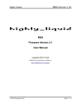
in response to MIDI events. The MD24 divides
the range of servo arm travel into 128 equallyspaced positions corresponding to the 128
possible values of a MIDI control parameter, as
shown in Figure 3-4. The output's mode and
other settings in the MIDI Configuration SysEx
Message determine which MIDI parameter
controls the output.
The characteristics of the signal generated by a
servo mode output can be adjusted via the PWM
Configuration SysEx Message. The message
can be used to alter the range of motion of a
connected servo. It also allows the MD24 to
control servos of differing control signal
specifications.
Logic mode outputs are
unaffected by settings in the PWM
Configuration SysEx Message.
Some MD24 output modes are MIDI channelspecific. Each MD24 output uses either an
independent channel setting or the “global”
channel setting specified by DIP switch SW1.
The contents of the MIDI Configuration SysEx
Message determine which type of channel
setting is used.
The MD24 ships preloaded with a default
configuration. The default configuration can be
restored at any time via the Initialization Jumper.
Instructions for using a PC to create and send
SysEx messages can be found at:
http://highlyliquid.com/hl2012/blog/61
© 2010 Sonarcana LLC
Page 2 / 17
Highly Liquid
MD24 Firmware Version 1.2
2.0 MIDI Configuration
2.2.2 Output Number (nn)
2.1 Overview
Parameter nn specifies which MD24 output is
configured by the three bytes that follow it. The
valid range is 00 to 17 hex, corresponding to
MD24 outputs 0 to 23.
The MD24 ships with a preloaded default MIDI
configuration. The MIDI Configuration SysEx
Message is used to alter the behavior of one or
more MD24 outputs.
2.2 MIDI Configuration SysEx
Message
Figure 2-1 shows the format of the MIDI
Configuration SysEx Message. The message
consists of a fixed header, a variable length
body, and a fixed footer.
The body of the message consists of a single
“pulse length” variable plus one or more 4 byte
blocks, each specifying the configuration of a
single MD24 output. The configuration of
outputs not specified in the message will remain
unchanged.
2.2.3 Output Mode (mm)
Parameter mm specifies the output mode for the
output specified by nn. Valid range is 00 to 2E
hex. The meanings of ch and ss depend on the
value of mm. Table 2-2 lists each output mode
and the associated meanings of ch and ss.
Each output mode is categorized as a logic mode
or servo mode. The characteristics of servo
mode outputs can be adjusted via the PWM
Configuration SysEx Message.
The Activity LED blinks three times upon
receipt of a properly formatted SysEx
configuration message. If no indication is given,
the MD24 configuration has not been changed.
Servo modes are available in both “Forward”
and “Reverse”. The direction refers to the travel
(clockwise / counter-clockwise) of the servo arm
in response to a change in the MIDI control
parameter. Arm travel for some servo models is
the opposite of travel for other models. Use
trial-and-error to determine whether “forward”
or “reverse” is the correct choice for your
application.
Configuration is retained when the MD24 is
disconnected from a power supply.
2.2.4 MIDI Channel (ch)
2.2.1 Pulse Length (pp)
The MD24 can generate output pulses in
response to MIDI notes. See “note trigger”
modes 01h and 02h. The value of pp determines
the behavior of all outputs using these modes.
When pp=00h, the duration of the MIDI note
will determine the duration of the output pulse.
When pp>00h, the output pulse will have a fixed
length, independent of the note's duration. The
length of the pulse is determined by the formula:
Some output modes respond to channel-specific
MIDI messages (see Table 2-2). Outputs thus
configured can respond to the channel specified
by DIP switch SW1, a specific channel
independent of other outputs, or to all channels
(“Omni”). See Table 2-3.
2.2.5 Selector (ss)
The meaning of ss depends on the value of the
corresponding mm. See Table 2-2.
(pp-1) × 4ms < pulse length < pp × 4ms
The valid range for pp is 00h to 7Fh.
© 2010 Sonarcana LLC
Page 3 / 17
Highly Liquid
MD24 Firmware Version 1.2
2.4 Default Configuration
2.3 DIP Switch Channel
Selection
Each MD24 output can use either an
independent MIDI channel setting or the
“global” channel setting specified by DIP switch
SW1. The contents of the MIDI Configuration
SysEx Message determine which outputs, if any,
use the DIP switch channel setting.
The MD24 ships with a preloaded default MIDI
configuration which can be expressed as an
equivalent SysEx configuration message. See
Figure 2-2. In the default configuration, MD24
outputs use “note trigger” mode for a block of
MIDI notes beginning with Middle C. Each
output uses the MIDI channel specified by the
DIP switch SW1.
Note: Changes to the DIP switch setting take
effect only at power-up.
2.5 Examples
Table 2-1 shows the SW1 settings for each
channel.
Table 2-1: MIDI Channel Selection
MIDI
Channel
SW1 Setting
1
2
3
4
1
off
off
off
off
2
off
off
off
on
3
off
off
on
off
4
off
off
on
on
5
off
on
off
off
6
off
on
off
on
7
off
on
on
off
8
off
on
on
on
9
on
off
off
off
10
on
off
off
on
11
on
off
on
off
12
on
off
on
on
13
on
on
off
off
14
on
on
off
on
15
on
on
on
off
16
on
on
on
on
© 2010 Sonarcana LLC
Figure 2-3 shows a configuration which uses
MIDI CC messages to control each MD24
output in servo mode. MIDI controllers 0 to 23
are used.
Figure 2-4 uses 14 bits from the bank number
(CC #0 and #32) and 7 bits from the program
number to control the state of 21 logic outputs.
Each bank/program combination will cause a
unique combination of on/off output states.
Figure 2-5 assigns a pair of outputs to each of 12
notes. The first output in each pair is a note
trigger. The second output in each pair is a
servo mode output which sets the servo arm
position in response to the velocity of the
corresponding note.
Page 4 / 17
Highly Liquid
MD24 Firmware Version 1.2
Figure 2-1: MIDI Configuration SysEx Message Format (Hex)
Header
(6 bytes)
Pulse Length
(1 byte)
F0 00 01 5D 03 01
pp
MIDI Configuration
(repeat as desired)
nn
mm
ch
Footer
(1 byte)
ss
F7
Table 2-2: Output Modes
mm
Type Mode Description
(Hex)
00
N/A
Disabled
Output is "off".
ch
ss
Ignored
Ignored
01
Note Trigger
MIDI
Logic Output is "on" for the duration of a corresponding MIDI note, and "off"
channel
otherwise. A fixed length pulse can be specified using parameter pp.
Note
number
(hex)
02
Inverted Note Trigger
MIDI
Logic Output is "off" for the duration of a corresponding MIDI note, and "on"
channel
otherwise. A fixed length pulse can be specified using parameter pp.
Note
number
(hex)
03
Note Toggle
MIDI
Logic Output state is toggled & latched upon receipt of a matching Note On message.
channel
Initial output state is “off”.
Note
number
(hex)
04
Note Number – Bit 0
MIDI
Logic Output state corresponds to bit 0 of the note number of the most recent Note On
channel
message. Bit 0 is the least significant bit.
Ignored
05
Note Number – Bit 1
MIDI
Logic Output state corresponds to bit 1 of the note number of the most recent Note On
channel
message.
Ignored
06
Note Number – Bit 2
MIDI
Logic Output state corresponds to bit 2 of the note number of the most recent Note On
channel
message.
Ignored
07
Note Number – Bit 3
MIDI
Logic Output state corresponds to bit 3 of the note number of the most recent Note On
channel
message.
Ignored
08
Note Number – Bit 4
MIDI
Logic Output state corresponds to bit 4 of the note number of the most recent Note On
channel
message.
Ignored
09
Note Number – Bit 5
MIDI
Logic Output state corresponds to bit 5 of the note number of the most recent Note On
channel
message.
Ignored
0A
Note Number – Bit 6
MIDI
Logic Output state corresponds to bit 6 of the note number of the most recent Note On
channel
message. Bit 6 is the most significant bit.
Ignored
0B
Note Velocity – Bit 0
MIDI
Logic Output state corresponds to bit 0 of the note velocity of the most recent Note On
channel
message. Bit 0 is the least significant bit.
Ignored
0C
Note Velocity – Bit 1
MIDI
Logic Output state corresponds to bit 1 of the note velocity of the most recent Note On
channel
message.
Ignored
© 2010 Sonarcana LLC
Page 5 / 17
Highly Liquid
MD24 Firmware Version 1.2
Table 2-2: Output Modes (Continued)
mm Mode
Mode Description
(Hex) Type
ch
ss
0D
Note Velocity – Bit 2
MIDI
Logic Output state corresponds to bit 2 of the note velocity of the most recent Note On
channel
message.
Ignored
0E
Note Velocity – Bit 3
MIDI
Logic Output state corresponds to bit 3 of the note velocity of the most recent Note On
channel
message.
Ignored
0F
Note Velocity – Bit 4
MIDI
Logic Output state corresponds to bit 4 of the note velocity of the most recent Note On
channel
message.
Ignored
10
Note Velocity – Bit 5
MIDI
Logic Output state corresponds to bit 5 of the note velocity of the most recent Note On
channel
message.
Ignored
11
Note Velocity – Bit 6
MIDI
Logic Output state corresponds to bit 6 of the note velocity of the most recent Note On
channel
message. Bit 6 is the most significant bit.
Ignored
12
Controller – Bit 0
MIDI
Logic Output state corresponds to bit 0 of the controller (CC) position. Bit 0 is the least
channel
significant bit.
Controller
number
(hex)
13
Logic
Controller – Bit 1
Output state corresponds to bit 1 of the controller (CC) position.
MIDI
channel
Controller
number
(hex)
14
Logic
Controller – Bit 2
Output state corresponds to bit 2 of the controller (CC) position.
MIDI
channel
Controller
number
(hex)
15
Logic
Controller – Bit 3
Output state corresponds to bit 3 of the controller (CC) position.
MIDI
channel
Controller
number
(hex)
16
Logic
Controller – Bit 4
Output state corresponds to bit 4 of the controller (CC) position.
MIDI
channel
Controller
number
(hex)
17
Logic
Controller – Bit 5
Output state corresponds to bit 5 of the controller (CC) position.
MIDI
channel
Controller
number
(hex)
18
Controller – Bit 6
MIDI
Logic Output state corresponds to bit 6 of the controller (CC) position. Bit 6 is the
channel
most significant bit.
Controller
number
(hex)
19
Program Change – Bit 0
MIDI
Logic Output state corresponds to bit 0 of the current program number. Bit 0 is the
channel
least significant bit.
Ignored
1A
Logic
Program Change – Bit 1
Output state corresponds to bit 1 of the current program number.
MIDI
channel
Ignored
1B
Logic
Program Change – Bit 2
Output state corresponds to bit 2 of the current program number.
MIDI
channel
Ignored
1C
Logic
Program Change – Bit 3
Output state corresponds to bit 3 of the current program number.
MIDI
channel
Ignored
© 2010 Sonarcana LLC
Page 6 / 17
Highly Liquid
MD24 Firmware Version 1.2
Table 2-2: Output Modes (Continued)
mm Mode
Mode Description
(Hex) Type
ch
ss
1D
Logic
Program Change – Bit 4
Output state corresponds to bit 4 of the current program number.
MIDI
channel
Ignored
1E
Logic
Program Change – Bit 5
Output state corresponds to bit 5 of the current program number.
MIDI
channel
Ignored
1F
Program Change – Bit 6
MIDI
Logic Output state corresponds to bit 6 of the current program number. Bit 6 is the
channel
most significant bit.
Ignored
20
Sync: Run
Logic MIDI Start and Continue messages latch output “on.”
latches output "off.”
MIDI Stop message Ignored
Ignored
21
Note Number - Forward
MIDI
Servo Servo position corresponds to the note number from the most recent Note On
channel
message.
Ignored
22
Note Number - Reverse
MIDI
Servo Servo position corresponds to the note number from the most recent Note On
channel
message.
Ignored
23
Note Velocity - Forward
MIDI
Servo Servo position corresponds to the note velocity from the most recent Note On
channel
message.
Note
number
24
Note Velocity - Reverse
MIDI
Servo Servo position corresponds to the note velocity from the most recent Note On
channel
message.
Note
number
25
Servo
Aftertouch - Forward
Servo position corresponds to aftertouch value.
MIDI
channel
Note
number
26
Servo
Aftertouch - Reverse
Servo position corresponds to aftertouch value.
MIDI
channel
Note
number
27
Servo
Controller - Forward
Servo position corresponds to controller position.
MIDI
channel
Controller
number
28
Servo
Controller - Reverse
Servo position corresponds to controller position.
MIDI
channel
Controller
number
29
Servo
Program Change - Forward
Servo position corresponds to the current program number.
MIDI
channel
Ignored
2A
Servo
Program Change - Reverse
Servo position corresponds to the current program number.
MIDI
channel
Ignored
2B
Servo
Channel Pressure - Forward
Servo position corresponds to channel pressure value.
MIDI
channel
Ignored
2C
Servo
Channel Pressure - Reverse
Servo position corresponds to channel pressure value.
MIDI
channel
Ignored
2D
Servo
Pitch Wheel - Forward
Servo position corresponds to pitch wheel position.
MIDI
channel
Ignored
2E
Servo
Pitch Wheel - Reverse
Servo position corresponds to pitch wheel position.
MIDI
channel
Ignored
© 2010 Sonarcana LLC
Page 7 / 17
Highly Liquid
MD24 Firmware Version 1.2
Table 2-3: MIDI Channel
ch (Hex)
Channel Setting
00
Channel as specified by DIP switch SW1.
01
Channel 1
02
Channel 2
03
Channel 3
04
Channel 4
05
Channel 5
06
Channel 6
07
Channel 7
08
Channel 8
09
Channel 9
0A
Channel 10
0B
Channel 11
0C
Channel 12
0D
Channel 13
0E
Channel 14
0F
Channel 15
10
Channel 16
11
Omni: events on all channels are used to update output state.
© 2010 Sonarcana LLC
Page 8 / 17
Highly Liquid
MD24 Firmware Version 1.2
Figure 2-2: Default Equivalent MIDI Configuration SysEx Message
Section
Bytes (Hex)
Header
F0 00 01 5D 03 01 Fixed Data
Pulse Length
00
Note duration determines note trigger pulse length.
Output 0 Configuration
00 01 00 3C
Note Trigger: Note #60 (Middle C)
Output 1 Configuration
01 01 00 3D
Note Trigger: Note #61
Output 2 Configuration
02 01 00 3E
Note Trigger: Note #62
Output 3 Configuration
03 01 00 3F
Note Trigger: Note #63
Output 4 Configuration
04 01 00 40
Note Trigger: Note #64
Output 5 Configuration
05 01 00 41
Note Trigger: Note #65
Output 6 Configuration
06 01 00 42
Note Trigger: Note #66
Output 7 Configuration
07 01 00 43
Note Trigger: Note #67
Output 8 Configuration
08 01 00 44
Note Trigger: Note #68
Output 9 Configuration
09 01 00 45
Note Trigger: Note #69
Output 10 Configuration 0A 01 00 46
Note Trigger: Note #70
Output 11 Configuration 0B 01 00 47
Note Trigger: Note #71
Output 12 Configuration 0C 01 00 48
Note Trigger: Note #72
Output 13 Configuration 0D 01 00 49
Note Trigger: Note #73
Output 14 Configuration 0E 01 00 4A
Note Trigger: Note #74
Output 15 Configuration 0F 01 00 4B
Note Trigger: Note #75
Output 16 Configuration 10 01 00 4C
Note Trigger: Note #76
Output 17 Configuration 11 01 00 4D
Note Trigger: Note #77
Output 18 Configuration 12 01 00 4E
Note Trigger: Note #78
Output 19 Configuration 13 01 00 4F
Note Trigger: Note #79
Output 20 Configuration 14 01 00 50
Note Trigger: Note #80
Output 21 Configuration 15 01 00 51
Note Trigger: Note #81
Output 22 Configuration 16 01 00 52
Note Trigger: Note #82
Output 23 Configuration 17 01 00 53
Note Trigger: Note #83
Footer
Fixed Data
© 2010 Sonarcana LLC
F7
Meaning
Page 9 / 17
Highly Liquid
MD24 Firmware Version 1.2
Figure 2-3: Servo Control via MIDI CC Message
Section
Bytes (Hex)
Meaning
Header
F0 00 01 5D 03 01 Fixed Data
Pulse Length
00
Note duration determines note trigger pulse length.
Output 0 Configuration
00 27 00 00
Servo Control: CC #0
Output 1 Configuration
01 27 00 01
Servo Control: CC #1
Output 2 Configuration
02 27 00 02
Servo Control: CC #2
Output 3 Configuration
03 27 00 03
Servo Control: CC #3
Output 4 Configuration
04 27 00 04
Servo Control: CC #4
Output 5 Configuration
05 27 00 05
Servo Control: CC #5
Output 6 Configuration
06 27 00 06
Servo Control: CC #6
Output 7 Configuration
07 27 00 07
Servo Control: CC #7
Output 8 Configuration
08 27 00 08
Servo Control: CC #8
Output 9 Configuration
09 27 00 09
Servo Control: CC #9
Output 10 Configuration 0A 27 00 0A
Servo Control: CC #10
Output 11 Configuration 0B 27 00 0B
Servo Control: CC #11
Output 12 Configuration 0C 27 00 0C
Servo Control: CC #12
Output 13 Configuration 0D 27 00 0D
Servo Control: CC #13
Output 14 Configuration 0E 27 00 0E
Servo Control: CC #14
Output 15 Configuration 0F 27 00 0F
Servo Control: CC #15
Output 16 Configuration 10 27 00 10
Servo Control: CC #16
Output 17 Configuration 11 27 00 11
Servo Control: CC #17
Output 18 Configuration 12 27 00 12
Servo Control: CC #18
Output 19 Configuration 13 27 00 13
Servo Control: CC #19
Output 20 Configuration 14 01 00 14
Servo Control: CC #20
Output 21 Configuration 15 01 00 15
Servo Control: CC #21
Output 22 Configuration 16 01 00 16
Servo Control: CC #22
Output 23 Configuration 17 01 00 17
Servo Control: CC #23
Footer
Fixed Data
© 2010 Sonarcana LLC
F7
Page 10 / 17
Highly Liquid
MD24 Firmware Version 1.2
Figure 2-4: On/Off by Bank Select & Program Change
Section
Bytes (Hex)
Header
F0 00 01 5D 03 01 Fixed Data
Pulse Length
00
Note duration determines note trigger pulse length.
Output 0 Configuration
00 19 00 00
Program Change: Bit 0
Output 1 Configuration
01 1A 00 00
Program Change: Bit 1
Output 2 Configuration
02 1B 00 00
Program Change: Bit 2
Output 3 Configuration
03 1C 00 00
Program Change: Bit 3
Output 4 Configuration
04 1D 00 00
Program Change: Bit 4
Output 5 Configuration
05 1E 00 00
Program Change: Bit 5
Output 6 Configuration
06 1F 00 00
Program Change: Bit 6
Output 7 Configuration
07 12 00 20
Controller #32 (Bank Select L): Bit 0
Output 8 Configuration
08 13 00 20
Controller #32 (Bank Select L): Bit 1
Output 9 Configuration
09 14 00 20
Controller #32 (Bank Select L): Bit 2
Output 10 Configuration 0A 15 00 20
Controller #32 (Bank Select L): Bit 3
Output 11 Configuration 0B 16 00 20
Controller #32 (Bank Select L): Bit 4
Output 12 Configuration 0C 17 00 20
Controller #32 (Bank Select L): Bit 5
Output 13 Configuration 0D 18 00 20
Controller #32 (Bank Select L): Bit 6
Output 14 Configuration 0E 12 00 00
Controller #0 (Bank Select H): Bit 0
Output 15 Configuration 0F 13 00 00
Controller #0 (Bank Select H): Bit 1
Output 16 Configuration 10 14 00 00
Controller #0 (Bank Select H): Bit 2
Output 17 Configuration 11 15 00 00
Controller #0 (Bank Select H): Bit 3
Output 18 Configuration 12 16 00 00
Controller #0 (Bank Select H): Bit 4
Output 19 Configuration 13 17 00 00
Controller #0 (Bank Select H): Bit 5
Output 20 Configuration 14 18 00 00
Controller #0 (Bank Select H): Bit 6
Output 21 Configuration 15 00 00 00
Disabled
Output 22 Configuration 16 00 00 00
Disabled
Output 23 Configuration 17 00 00 00
Disabled
Footer
Fixed Data
© 2010 Sonarcana LLC
F7
Meaning
Page 11 / 17
Highly Liquid
MD24 Firmware Version 1.2
Figure 2-5: Note Trigger Logic & Note Velocity Servo
Section
Bytes (Hex)
Meaning
Header
F0 00 01 5D 03 01 Fixed Data
Pulse Length
00
Note duration determines note trigger pulse length.
Output 0 Configuration
00 01 00 3C
Note Trigger: Note #60 (Middle C)
Output 1 Configuration
01 23 00 3C
Servo: Note Velocity: Note #60
Output 2 Configuration
02 01 00 3D
Note Trigger: Note #61
Output 3 Configuration
03 23 00 3D
Servo: Note Velocity: Note #61
Output 4 Configuration
04 01 00 3E
Note Trigger: Note #62
Output 5 Configuration
05 23 00 3E
Servo: Note Velocity: Note #62
Output 6 Configuration
06 01 00 3F
Note Trigger: Note #63
Output 7 Configuration
07 23 00 3F
Servo: Note Velocity: Note #63
Output 8 Configuration
08 01 00 40
Note Trigger: Note #64
Output 9 Configuration
09 23 00 40
Servo: Note Velocity: Note #64
Output 10 Configuration 0A 01 00 41
Note Trigger: Note #65
Output 11 Configuration 0B 23 00 41
Servo: Note Velocity: Note #65
Output 12 Configuration 0C 01 00 42
Note Trigger: Note #66
Output 13 Configuration 0D 23 00 42
Servo: Note Velocity: Note #66
Output 14 Configuration 0E 01 00 43
Note Trigger: Note #67
Output 15 Configuration 0F 23 00 43
Servo: Note Velocity: Note #67
Output 16 Configuration 10 01 00 44
Note Trigger: Note #68
Output 17 Configuration 11 23 00 44
Servo: Note Velocity: Note #68
Output 18 Configuration 12 01 00 45
Note Trigger: Note #69
Output 19 Configuration 13 23 00 45
Servo: Note Velocity: Note #69
Output 20 Configuration 14 01 00 46
Note Trigger: Note #70
Output 21 Configuration 15 23 00 46
Servo: Note Velocity: Note #70
Output 22 Configuration 16 01 00 47
Note Trigger: Note #71
Output 23 Configuration 17 23 00 47
Servo: Note Velocity: Note #71
Footer
Fixed Data
© 2010 Sonarcana LLC
F7
Page 12 / 17
Highly Liquid
3.0 PWM Configuration
3.1 Overview
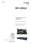
A servo is controlled by a pulse width
modulation (PWM) signal—a continuously
repeating 5V pulse. The frequency of pulses is
called the “refresh rate”. At any point in time,
servo arm position is set by the width of the
most recent pulse—changes to pulse width cause
motion of the servo arm.
Different servo models require different ranges
of pulse width.
Consult your servo
documentation for the characteristics of the
required control signal.
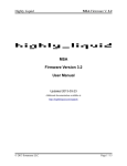
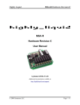
Typical radio control (“RC”) servos accept
pulse widths between 1ms and 2ms for
approximately 90º of arm travel (Figure 3-1).
MD24 servo mode outputs using the default
PWM configuration will generate pulses in this
range.
The PWM signal generated by an MD24 servo
mode output can be adjusted via the PWM
Configuration SysEx Message. Each output can
be adjusted independently to alter the range of
arm travel for a connected servo or to
accommodate servos with differing PWM
control requirements.
MD24 Firmware Version 1.2
The Activity LED blinks three times upon
receipt of a properly formatted SysEx
configuration message. If no indication is given,
the MD24 configuration has not been changed.
Configuration is retained when the MD24 is
disconnected from a power supply.
The direction (clockwise / counter-clockwise) of
servo arm travel in response to a given change in
control parameter value is determined by the
output mode as specified in the MIDI
Configuration SysEx Message.
3.2.1 Output Number (nn)
Parameter nn specifies which MD24 output is
configured by the three bytes that follow it. The
valid range is 00 to 17 hex, corresponding to
MD24 outputs 0 to 23.
3.2.2 Minimum Pulse Width (ww)
Parameter ww specifies the minimum pulse
width of the PWM servo control signal, based
on the following formula:
minimum pulse width = (ww + 1) × 64μs
The valid range for ww is 00 to 3F hex.
3.2.3 Pulse Width Step (ss)
3.2 PWM Configuration SysEx
Message
Figure 3-2 shows the format of the PWM
Configuration SysEx Message. The message
consists of a fixed header, a variable length
body, and a fixed footer.
The body of the message consists of one or more
4 byte blocks, each specifying the PWM
configuration of a specific MD24 output. The
configuration of outputs not specified in the
message will remain unchanged.
Outputs which are configured in logic modes are
unaffected by the settings from the PWM
Configuration SysEx Message.
© 2010 Sonarcana LLC
Parameter ss specifies the change in pulse width
for each increment or decrement in the
associated MIDI control value, based on the
following formula:
pulse width step = (ss + 1) × 0.25μs
The valid range for ss is 00 to 7F hex.
3.2.4 Initial Position (pp)
Parameter pp specifies the initial position of the
servo upon MD24 power-up. Valid range is 00
to 7F hex.
Page 13 / 17
Highly Liquid
3.2.5 Maximum Pulse Width
The maximum pulse width can be calculated
using the values ww and ss as follows:
maximum pulse width =
[(ww + 1) × 64μs] + [(ss + 1) × 32μs]
3.3 Refresh Rate
The MD24 refreshes each servo mode output in
series. By default, the MD24 will initiate
refresh cycles at 20 ms intervals, for a refresh
rate of 50 Hz.
The quantity and configuration of servo mode
outputs may affect the servo refresh rate. At any
time, the actual refresh period will be the greater
of 20 ms or the sum of all servo mode output
pulse lengths.
3.4 Default Configuration
The MD24 ships with a preloaded PWM
configuration which can be expressed as an
equivalent SysEx configuration message. See
Figure 3-3.
MD24 Firmware Version 1.2
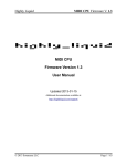
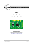
Figure 3-5 shows the altered range of servo arm
travel, given that the step width is reduced by
half. Note that the range of arm travel has also
been reduced by half (from 90º to 45º). The
servo responds to the full range (0-127) of the
MIDI control parameter, but each increment in
the value causes a smaller movement.
Figure 3-6 shows the effect of changes to ww.
Because the value for ss is the same as that in
figure Figure 3-5, the servo arm covers a range
of 45º. But because the minimum pulse width
has been increased by approximately 0.5ms, the
range of travel is shifted by 45º.
Choice of values for ww and ss will depend both
on the characteristics of the connected servo and
on the desired range of servo arm travel.
Most servos are mechanically limited to a 180º
range of arm travel. If the control signal
specifies a position outside the mechanical range
of the servo arm, the servo may “strain” against
its mechanical stop. If maximum arm travel is
desired, use trial-and-error to find the
appropriate PWM configuration.
The default PWM configuration is intended to
accommodate typical “radio control”-type
servos. Under default settings, a servo mode
output will generate a signal with a pulse width
varying between approximately 1ms and 2ms.
This will cause a 90º range of motion of the
servo arm. Some servo models may require
adjustment of the PWM configuration.
Note that the default PWM settings are unused
unless an output is configured in servo mode by
a MIDI Configuration SysEx Message.
3.5 Examples
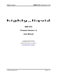
Figure 3-4 shows servo arm position as a
function of MIDI control parameter value,
assuming that the servo is a typical RC servo,
and that the MD24 output uses the default PWM
configuration.
© 2010 Sonarcana LLC
Page 14 / 17
Highly Liquid
MD24 Firmware Version 1.2
Figure 3-1: RC Servo Arm Travel & PWM Signal
Figure 3-2: PWM Configuration SysEx Message Format (Hex)
Header
(7 bytes)
PWM Configuration
(repeat as desired)
F0 00 01 5D 03 02 00
nn
ww
ss
Footer
(1 byte)
pp
F7
Figure 3-3: Default Equivalent PWM Configuration SysEx Message
Section
Bytes (Hex)
Meaning
Header
F0 00 01 5D 03 02 00 Fixed Data
Output nn Configuration
for nn = [00..17] hex
nn 0F 1D 3F
Minimum Pulse Width = 1.02ms;
Pulse Width Step = 7.5μs;
Maximum Pulse Width = 1.98ms;
Initial Position = 63
Footer
F7
Fixed Data
© 2010 Sonarcana LLC
Page 15 / 17
Highly Liquid
MD24 Firmware Version 1.2
Figure 3-4: Servo Arm Travel (RC Servo; ww = 0Fh; ss = 1Dh)
Figure 3-5: Servo Arm Travel (RC Servo; ww = 0Fh; ss = 0Eh)
Figure 3-6: Servo Arm Travel (RC Servo; ww = 17h; ss = 0Eh)
© 2010 Sonarcana LLC
Page 16 / 17
Highly Liquid
MD24 Firmware Version 1.2
4.0 Initialization Jumper
At any time, the default MIDI configuration and
default
PWM
configuration
can
be
simultaneously restored by connecting the two
terminals of the “INIT” jumper JP1 and
simultaneously powering up the MD24. Upon
use of the INIT Jumper, the Activity LED will
blink 6 times, and any user-specified
configuration
will
be
lost.
5.0 Indicator LEDs
The MD24 has two indicator LEDs: PWR
(Power) and ACT (Activity).
The Power LED indicates the presence of a
connected power supply. If the Power LED
switches off or “dims” during operation, an
inadequate power supply or overloading of
MD24 outputs is indicated.
The Activity LED blinks briefly when the MD24
processes any MIDI event that affects the state
of any output. MIDI events which do not match
the configured output modes will not cause an
activity indication.
When any properly formatted SysEx
configuration message is received, the Activity
LED will blink three times. Use of the INIT
Jumper will cause the Activity LED to blink six
times.
The Activity LED performs a brief self-test upon
power-up.
© 2010 Sonarcana LLC
Page 17 / 17