1
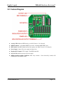
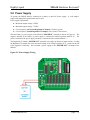
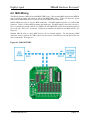
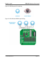
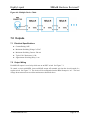
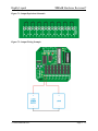
Highly Liquid
MSA-R Hardware Revision C
MSA-R
Hardware Revision C
User Manual
Updated 2009-01-28
Additional documentation available at:
http://highlyliquid.com/support/
© 2008 Sonarcana LLC
Page 1 / 11
Highly Liquid
MSA-R Hardware Revision C
Table of Contents
1.0 Important Safety Information...................................................................................................2
2.0 Assembly Instructions...............................................................................................................2
3.0 Feature Diagram........................................................................................................................5
4.0 Mechanical Drawing.................................................................................................................6
5.0 Power Supply............................................................................................................................7
6.0 MIDI Wiring.............................................................................................................................8
7.0 Outputs....................................................................................................................................10
7.1 Electrical Specifications.....................................................................................................10
7.2 Output Wiring.....................................................................................................................10
1.0 Important Safety Information
To prevent damage to the MSA-R and connected devices, and to prevent personal injury:
●
Carefully follow the assembly instructions. Assembly errors can cause overheating and excess
power consumption. The electrolytic capacitors contained in the kit may explode if mounted
backwards.
●
Take reasonable static-control precautions when assembling & handling the kit. This product
includes ESD-sensitive parts.
●
Use an appropriate power source.
●
Do not exceed the electrical specifications of the MSA-R relay outputs.
2.0 Assembly Instructions
The MSA-R consists of a printed circuit board (PCB, Figure 2.1) and several electronic components
which must be mounted on the PCB by soldering. Use conventional tin/lead solder or lead-free solder.
When soldering, always wear eye protection and work in a well-ventilated area.
Before assembly, examine all of the components in the kit and identify them using the parts list (Table
2-1). Some parts may be packaged separately inside the kit for easier identification.
Follow the assembly instructions for each component in Table 2-1. Location is indicated by the white
legend on the PCB. Mount & solder the smallest components first, then proceed with components of
increasing size.
Insert parts into the top (legend side) of the board and apply solder to the underside. Masking tape may
be used to temporarily hold smaller components in place. After soldering is complete, trim the
component leads from the underside of the PCB.
© 2008 Sonarcana LLC
Page 2 / 11
Highly Liquid
MSA-R Hardware Revision C
Figure 2.1: MSA-R PCB
Table 2-1: Parts List
Part
Image Notes
C1 –
C4
0.1μF capacitor. Polarity: none.
C5 C6
Electrolytic capacitor. Polarity: the positive lead (the longer of the two) must match the "+" symbol on
the circuit board legend.
D1
Small signal diode. Polarity: dark band on diode must match the white band on the circuit board
legend.
D2
Rectifier diode. Polarity: white band on diode must match the white band on the circuit board legend.
IC1
Microcontroller. Mount socket on circuit board first, then insert IC into socket. Notched end must
match notch in the circuit board legend.
© 2008 Sonarcana LLC
Page 3 / 11
Highly Liquid
MSA-R Hardware Revision C
Table 2-1: Parts List (Continued)
Part
Image Notes
IC2
Mount socket on circuit board first, then insert IC into socket. End marked with dot must match notch
in the circuit board legend.
IC3
Pin 1 is on the left in the photo. Pin 1 must match dot on the circuit board legend.
IC4
Hex inverter. Mount socket on circuit board first, then insert IC into socket. Notched end must match
notch in the circuit board legend.
K0 - K7
Reed relay. Pin 1 is marked with an angled edge on the top of case or a notch on the label side of case.
Relay must be inserted so that pin 1 matches the marked end of the circuit board legend.
LED1 LED2
Polarity: the short lead must match the flat side on the circuit board legend.
0Ω resistor, marked with a single black band.
R0 - R7
Mount resistor vertically (on end).
R8
10kΩ resistor, marked with the following color bands: brown, black, orange, gold.
R9 R13
220Ω resistor, marked with the following color bands: red, red, brown, gold.
R14 R15
1kΩ resistor, marked with the following color bands: brown, black, red, gold.
RN1
Resistor Netowrk. Pin 1 (marked with a dot) must be inserted in the small box on the circuit board
legend.
SW1
DIP Switch. Numbers on switch should match numbers on circuit board legend.
© 2008 Sonarcana LLC
Page 4 / 11
Highly Liquid
MSA-R Hardware Revision C
3.0 Feature Diagram
●
Activity LED: Indicates MIDI activity (see MSA Firmware User Manual).
●
MIDI Terminals: 1 x Standard MIDI IN port and 2 x Standard MIDI THRU port.
●
DIP Switch: Sets MIDI channel and/or note response (see MSA Firmware User Manual).
●
Power Input: Connect DC power supply or battery here.
●
Regulated 5V Output: 5VDC output. Not MIDI-controlled.
●
Power LED: Indicates presence of power supply.
●
MIDI-Controlled Output Terminals: Reed relay contacts.
terminal pair acts an SPST switch.
© 2008 Sonarcana LLC
Each electrically isolated A/B
Page 5 / 11
Highly Liquid
MSA-R Hardware Revision C
4.0 Mechanical Drawing
© 2008 Sonarcana LLC
Page 6 / 11
Highly Liquid
MSA-R Hardware Revision C
5.0 Power Supply
To operate, the MSA-R must be connected to a battery or other DC power supply. A “wall adapter”
supply with appropriate specifications may be used.
Power supply requirements:
●
Maximum output voltage: 12VDC
●
Minimum output voltage: 7.5VDC
●
Current capacity (no load on Regulated 5V Output): 110mA or greater
●
Current capacity (loaded Regulated 5V Output): Varies with 5V load current
Wire the battery or power supply to the MSA-R “POWER IN” terminals as shown in Figure 5.1. The
negative terminal of the battery or power supply is connected to MSA-R ground, marked “G”. The
positive terminal of the power supply or battery is connected to the terminal marked “+”.
The Regulated 5V Output (“POWER OUT” terminals) can supply up 500mA of output current. Loading
the Regulated 5V Output may cause increased heating of the voltage regulator (IC3). Attach a heat sink
to the regulator if necessary. Do not attach a power supply to the “POWER OUT” terminals of the
MSA-R.
Figure 5.1: Power Supply Wiring
© 2008 Sonarcana LLC
Page 7 / 11
Highly Liquid
MSA-R Hardware Revision C
6.0 MIDI Wiring
The MSA-R features a MIDI IN and dual MIDI THRU ports. The incoming MIDI signal on the MIDI IN
port is replicated exactly and output on each of the MIDI THRU ports. Figure 6.1 shows the typical
connection to other MIDI devices. Either or both of the THRU ports can be used.
MSA-R MIDI ports may be wired to MIDI connectors. The MIDI standard specifies a 5-position DIN
connector. Figure 6.2 shows MIDI receptacle pin numbering. The MIDI signal is carried by pins 4 & 5.
Pin 2 is connected to ground at the OUT or THRU side of the MIDI link, and is left unconnected at the IN
side of the link. Pins 1 & 3 are unused. Connector pin numbers are marked on the MSA-R PCB. See
Figure 6.3.
Multiple MSA-R units (or other MIDI devices) can be chained together. For this purpose, MIDI
connectors can be bypassed: the THRU port of one unit can be wired directly to the IN port of the next
device in the chain. See Figure 6.4.
Figure 6.1: MIDI IN/THRU
© 2008 Sonarcana LLC
Page 8 / 11
Highly Liquid
MSA-R Hardware Revision C
Figure 6.2: MIDI Receptacle Pin Numbering
Figure 6.3: MSA-R Remote MIDI Receptacle Wiring
© 2008 Sonarcana LLC
Page 9 / 11
Highly Liquid
MSA-R Hardware Revision C
Figure 6.4: Multiple-Device Chain
7.0 Outputs
7.1 Electrical Specifications
●
Contact Rating: 10W
●
Maximum Switching Voltage: 24 VAC
●
Maximum Switching Current: 500 mA
●
Typical "On" Resistance: 0.2 Ω
●
Approximate Switching Delay: 1 ms
7.2 Output Wiring
Each MSA-R output is a reed relay which acts as an SPST switch. See Figure 7.1.
To control a circuit with MIDI, insert an MSA-R output A/B terminal pair into the circuit instead of a
regular switch. See Figure 7.2. The circuit will be completed when the MSA-R output is “on”. The load
voltage & current must not exceed the maximums as described above.
© 2008 Sonarcana LLC
Page 10 / 11
Highly Liquid
MSA-R Hardware Revision C
Figure 7.1: Output Equivalent Schematic
Figure 7.2: Output Wiring Example
© 2008 Sonarcana LLC
Page 11 / 11