1
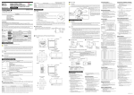
■ For DC Relay Wiring
3. How to Install
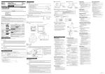
Model UP550
Program Controller
User’s Manual for Single-loop Control
Installation
Contents
Thank you for purchasing the UP550 program controller.
The controller is shipped from the factory with 7 hardcopy user’s manuals (A2 size) and 1 user’s manual on CD-ROM.
The 7 user’s manuals in hardcopy format describe the operating procedures required for basic use (factory-set to single-loop control
mode). It is recommended that you refer to these user’s manuals to understand [1] installation, [2] initial settings, [3] program settings
and [4] operating procedures of the controller.
The CD-ROM contains an User’s Manual (Reference) with descriptions of various functions and setting ranges that can be set as
necessary. The manual also contains information on operations used to carry out control other than single-loop control.
Moreover, the use of an optional parameter setting tool (model: LL100-E10) allows you to easily perform settings and adjustments with
a PC.
Description
A2-size paper,
back and front
Describes examples of setting PV input types and
control output types. Making settings described herein
and program creation in Programming User’s Manual
allows you to carry out basic control.
Describes examples of creating basic programs. The
use of the program pattern setup charts included in the
Program Parameters User’s Manual is recommended
A2-size paper,
back and front
General understandProgram Parameters
ing of programming
operations
Operating
Operations
procedures
and troubleshooting
Contains a parameter map that serves as a guide to
creating programs. Also includes a brief explanation
of the functions of program parameters.
Describes key operation sequences. For operation
control through external contact inputs, see the back of
Installation User’s Manual.
A2-size paper,
back and front
Brief operation
Contains the parameter map used as a guideline for
setting parameters.
Briefly describes the functions of parameters. In addition,
each parameter table has a User Setting column, where
you can record your setpoints when setting them in the
controller.
A2-size paper,
back and front
A2-size paper,
back and front
Explains more advanced applications than those found
in the 7 hardcopy user’s manuals (A2 size).
CD-ROM
Parameter Map
Function description
and setpoint
recording
Parameters
Detailed description User’s Manual
of functions
(Reference)
Rear of
controller
Unit: mm
A2-size paper,
back and front
100
General installation
[(N-1)96+92]
Make sure that all of the precautions are strictly adhered to. Yokogawa Electric Corporation assumes no liability for any
damage resulting from use of the instrument in contradiction to the precautions.
Also, Yokogawa Electric Corporation assumes no liability to any party for any loss or damage, direct or indirect, caused
by the use or any unpredictable defect of the instrument.
■ Regarding Protection, Safety, and Prohibition Against Unauthorized Modification
(1) In order to protect the product and the system controlled by it against damage and ensure its safe use, make certain that
all of the instructions and precautions relating to safety contained in this document are strictly adhered to. Yokogawa
does not guarantee safety if products are not handled according to these instructions.
(2) Modification of the product is strictly prohibited.
145 min.
“N” stands for the number of controllers to be
installed.
However, the measured value applies if N 5.
92
+0.8
0
92
+0.8
0
(25)
Large bracket
Panel
Direction to insert the
controller
Insert the controller
into the opening at
the front of the panel.
2. Model and Suffix Codes
(bottom mounting hardware)
Description
Program controller (provided with retransmission output and 15 VDC loop power supply as standard)
Standard type
Position proportional type
Heating/cooling type
None
With communication, auxiliary analog input (Note), and 1 additional DI
Recommended
tightening torque
:0.4N m
4. How to Connect Wires
1) Before carrying out wiring, turn off the power to the controller and check that the cables to be connected are not
alive with a tester or the like because there is a possibility of electric shock.
2) For the protection and safe use of the controller, be sure to place a circuit breaker (conforms with IEC60947,
5A, 100V or 220V AC) near the controller where the breaker can easily be operated. In addition, be sure to
indicated that it is the instrument to cut the power supply of the controller.
3) Wiring must be carried out by personnel who have basic electrical knowledge and practical experience.
Check that the following items are provided:
Program controller (of ordered model): ......................................................... 1
Brackets (mounting hardware): ...................................................................... 1 pair
Unit label: ....................................................................................................... 1
User’s Manuals for Single-loop Control: ....................................................... 7 (A2 size)
User’s Manual (Reference) (CD-ROM Version): ........................................... 1
NOTE
■ Correspondence between the Model and Suffix Codes, and the Contact Input/
Output Terminals Provided
Check the model ordered and the presence/absence of contact inputs and outputs in the following table.
✓ indicate that the contacts are available.
1
(top mounting hardware)
CAUTION
Note: Not used in single-loop control.
UP550-
After opening the mounting hole on the
panel, follow the procedures below to install the controller:
1. Insert the controller into the opening
from the front of the panel so that the
terminal board on the rear is at the far
Terminal board
side.
2. Set the brackets in place on the top and
bottom of the controller as shown in the
Insert a screwdriver into the
figure on the left, then tighten the
brackets to tighten the screws.
screws of the brackets. Take care not to
overtighten them.
Small bracket
Before using the controller, check that the model and suffix codes match your order.
Contact output terminals
DI2
DI3
DI4
DI5
DI6
DI7
✓
✓
✓
✓
✓
✓
✓
✓
✓
✓
✓
✓
3.7mm
or
Safety and EMC Standards
• Safety: Compliant with IEC/EN61010-1: 2001, approved by
CSA1010, approved by UL508.
Installation category : CAT. II (IEC/EN61010, CSA1010)
Pollution degree : 2 (IEC/EN61010, CSA1010)
Measurement category : I (CAT. I : IEC/EN61010)
Rated measurement input voltage : 10V DC max.(across
terminals), 300V AC max.(across ground)
Rated transient overvoltage : 1500V (Note)
Note : It is a value on the safety standard which is assumed
by IEC/EN61010-1 in measurement category I, and is not
the value which guarantees an apparatus performance.
For UP550
Part Number
T9115YD
Sales Unit
1
CAUTION
This equipment has Measurement category I, therefore do not use the equipment for measurements
within measurement categories II, III and IV.
Fold the cover in the direction
of the arrow.
Figure A
Measurement category
1
2
DI8
DO1
DO2
DO3
DO4
DO5
DO6
DO7
✓
✓
✓
✓
✓
✓
✓
✓
✓
✓
✓
✓
✓
✓
✓
Note: For details on the functions of contact inputs/outputs, see “Terminal Wiring Diagrams” on the back of the manual.
Remarks
Description
CAT.1 For measurements performed
on circuits not directly
connected to MAINS.
CAT.2 For measurements performed
on circuits directly connected
to the low voltage installation.
CAT.3 For measurements performed
in the building installation.
CAT.4 For measurements performed
at the source of the low-voltage
installation.
Appliances, portable
equipments, etc.
Distribution board,
circuit breaker, etc.
Overhead wire, cable
systems, etc.
Internal Wiring
3
1) Provide power from a single-phase instrument power supply. If there is a lot of noise in the power line, insert an
insulating transformer into the primary side of the line and use a line filter (recommended part: ZAC2205-00U
from TDK) on the secondary side.
As a countermeasures against noise, do not place the primary and secondary power cables close to each other.
2) For thermocouple input, use shielded compensating lead wires for wiring. For RTD input, use shielded wires
that have low conductor resistance and cause no significant differences in resistance between the three wires.
The cables to be used for wiring, terminal specifications, and recommended parts are as shown below.
3) Control output relays may be replaced. However, because they have a life of 100,000 times that of the resistance load, use auxiliary relays to turn on/off a load.
4) The use of inductance (L) loads such as auxiliary relays, motors and solenoid valves causes malfunction or
relay failure; always insert a CR filter for use with alternating current or a diode for use with direct current, as
a spark-removal surge suppression circuit, into the line in parallel with the load.
5) When there is possibility of being struck by external lightening surge, use the arrester to protect the instrument.
PV Input Signals
• Number of inputs: 1 (terminals 11 - 12 - 13 )
• Input type: Universal input system. The input type can be
selected with the software.
• Sampling period: Can be selected from 100, 200 and 500 ms.
• Burnout detection: Functions at TC, RTD, standard signal
(0.4 to 2 V or 1 to 5 V)
Upscale, downscale, and off can be specified.
For standard signal, burnout is determined to have occurred
if it is 0.1 V or less.
• Input bias current: 0.05 A (for TC or RTD b-terminal)
• Measurement current (RTD): About 0.13 mA
• Input resistance: 1 M or more for thermocouple or mV input
About 1 M for DC voltage input
• Allowable signal source resistance: 250 or less for
thermocouple or mV input
Effects of signal source resistance: 0.1 V/ or less
2 k or less for DC voltage input
Effects of signal source resistance: About 0.01%/100 • Allowable wiring resistance: for RTD input
Maximum 150 /wire: Conductor resistance between three
wires should be equal
However, 10 /wire for a maximum range of -150.0 to
150.0C.
Wire resistance effect: 0.1C /10 • Allowable input voltage: 10 V DC for thermocouple, mV, or
RTD input
20 V DC for DC voltage input
• Noise rejection ratio: 40 dB (50/60 Hz) or more in normal mode
120 dB (50/60 Hz) or more in common mode
• Reference junction compensation error: 1.0C (15 to 35C)
1.5C (0 to 15C, 35 to 50C)
• Applicable standards: JIS, IEC, DIN (ITS-90) for thermocouples
and RTD
Auxiliary Analog Input Signals
Available only for controllers with auxiliary analog input terminals.
These signals are not used in single-loop control, however.
• Number of inputs: 1 (terminals 21 - 22 )
• Input type: Settable in a range of 0-2, 0-10, 0.4-2.0, or 1-5 V DC
• Sampling period: 100, 200 and 500 ms
The sampling period of an auxiliary analog input signal is
associated with the PV input’s sampling period.
• Input resistance: About 1 M
• Input accuracy: 0.3% 1 digit of input span for 0 to 2 V DC
0.2%1 digit of input span for 0 to 10 V DC
0.375%1 digit of input span for 0.4 to 2.0 V DC
0.3%1 digit of input span for 1 to 5 V DC
Under standard operating conditions (232C, 5510%
RH, power frequency of 50/60 Hz)
Feedback Resistance Input
Provided for position proportional type only (terminals 45 - 46 - 47 )
• Slide resistance value: 100 to 2.5 k of overall resistance
(burnout detection for sliding wire provided)
• Measuring resolution: 0.1% of overall resistance
2
T
1
Outlet
5. Hardware Specifications
Turn off the power to the controller before installing it on the panel because there is a possibility of electric shock.
✓
✓
3.7mm
Entrance 4
Cable
IMPORTANT
DI1
0.8 N·m or less
+0.8
0
CAUTION
0
• PV display:
5-digit, 7-segment, red LEDs, character height of 20 mm
• Setpoint display: 32128 dot LCD with back lighting
• Status indicating lamps: LEDs
Figure B
■ Exemption from Responsibility
UP550-
0.3 to 1.65 mm2
8
Display Specifications
Tightening torque
Side-by-side close installation
117 min.
(53)
Contact input terminals
Applicable wire size
1
Purpose: Event output, FAIL output, and others
Number of outputs: 7 points
Relay contact rating: 240 V AC, 1 A, or 30 V DC, 1 A
Transistor contact rating: 24 V DC, 50 mA
3
Indicates that operating the hardware or software in a particular manner may damage it or result in a system failure.
Model and Suffix
Codes
Shielded wires
4
Draws attention to information that is essential for understanding the operation and/or features of the controller.
•
•
•
•
•
Other signals
7
UP550-
Contact Outputs
•
•
•
•
1 to 10 mm (Panel thickness)
■ How to Install
0
1
Shielded wires (three conductors), UL2482 (Hitachi Cable)
0
-
Small bracket
NOTE
Optional functions
RTD
2. Fit the holes on the top and bottom of the terminal cover
the projections on the brackets (Fig. B) and lock in
place. The figure right shows the attachment of a
terminal cover to UP controller.
The following symbols are used in the hardcopy user’s manuals and in the user’s manual supplied on the CD-ROM.
Type
-
A2-size paper,
back and front
This symbol on the controller indicates that the operator must refer to an explanation in the user’s manual in order to
avoid the risk of injury or death of personnel or damage to the instrument. The manual describes how the operator
should exercise special care to avoid electric shock or other dangers that may result in injury or loss of life.
-0
-1
-2
X-
Number of Inputs
UP550-
• Input type: Non-voltage contact or transistor open collector input
• Input contact rating: 12 V DC, 10 mA or more
• On/off determination: For non-voltage contact input, contact
resistance of 1 k or less is determined as “on” and contact
resistance of 20 k or more as “off.”
For transistor open collector input, input voltage of 2 V or
less is determined as “on” and leakage current must not
exceed 100 A when “off.”
• Minimum status detection hold time: PV input’s sampling
period 3
Fit the cover hold
over the protrusion
on the mounting bracket.
CAUTION
UP550
Shielded compensating lead wires, JIS C 1610,
(See Yokogawa Electric’s GS 6B1U1-E.)
Large bracket
PVE1
PVE2
The following symbol is indicated on the controller to ensure safe use.
Suffix Code
Thermocouple
1. Before attaching the terminal cover, bend the side with
the groove inward as shown in Fig. A. Be careful not to
bend it backwards. This not only marks it harder to
attach the cover but will also weaken its hold.
1. Safety Precautions
Model
Name and Manufacturer
Power supply, grounding, relay contact outputs 600 V PVC insulated wires, JIS C 3307, 0.9 to 2.0 mm2
● Terminal Covers (Optonal parts)
UP550
11
CR filter
(Mount it directly
to the relay coil
terminal (socket).)
+0.8
0
Programming
Must not
exceed 30
30
96
Relay
(Use one with a relay coil
rating less than the UP’s
contact rating.)
● Recommended Terminal Lugs
92
Program creation
Purpose
Front panel
of controller
96
Initial Settings
Install the controller at an angle within 30° from horizontal
with the front panel facing upward. Do not install it facing
downward. The position of right and left sides should be horizontal.
UP’s contact
● Cable Specifications and Recommended Cables
Target Model
Media
Describes the tasks (installation, wiring, and others)
required to make the controller ready for operations.
Basic operation
150mm
150mm
■ External Dimensions and Panel Cutout Dimensions
■ How to Use the Manuals
Installation
Relay
(Use one with a relay coil rating
less than the UP’s contact rating.)
● Installation Position
Introduction
Setup
150mm
150mm
Diode
(Mount it directly
to the relay coil
terminal (socket).)
UP’s contact
Never place the controller directly on flammable items or equipment.
If the controller has to be installed close to flammable items or equipment, be sure to provide shielding panels all
around the controller, at least 150mm away from every side; the panels should be made of either 1.43mm-thick
metal-plated steel plates or 1.6mm-thick uncoated steel plates.
1. Safety Precautions
2. Model and Suffix Codes
3. How to Install
4. How to Connect Wires
5. Hardware Specifications
6. Terminal Wiring Diagrams
Signal Isolations
• PV input terminals: Isolated from other input/output terminals.
Not isolated from the internal circuit.
• Auxiliary analog input terminals: Isolated from other input/
output terminals and the internal circuit
• 15 V DC loop power supply terminals: Not isolated from analog
current output nor voltage pulse control output. Isolated
from other input/output terminals and internal circuit.
• Analog current output terminals (for control output and
retransmission): Not isolated between current outputs nor
from 15 V DC loop power supply and voltage pulse control
output. Isolated from other input/output terminals and
internal circuit.
• Voltage pulse control output terminals: Not isolated from current
outputs and 15 V DC loop power supply. Isolated from
other input/output terminals and internal circuit.
• Relay contact control output terminals: Isolated between contact
output terminals and from other input/output terminals and
internal circuit.
• Contact input terminals: Not isolated between contact input
terminals and from communication terminals. Isolated from
other input/output terminals and internal circuit.
• Relay contact output terminals: Not isolated between relay
contact outputs. Isolated from other input/output terminals
and internal circuit.
• Transistor contact output terminals: Not isolated between
transistor contact outputs. Isolated from other input/output
terminals and internal circuit.
• RS-485 communication terminals: Not isolated from contact
input terminals. Isolated from other input/output terminals
and internal circuit.
• Feedback slide resistance input terminals: Not isolated from
analog current output terminals (control, retransmission), 15 V
DC sensor power supply, and voltage pulse control outputs.
Isolated from other input/output terminals and internal
circuit.
• Power terminals: Isolated from other input/output terminals and
internal circuit.
• Grounding terminals: Isolated from other input/output terminals
and internal circuit.
R
R
7 mm or less
This manual describes installation, wiring, and other tasks required to make the controller ready for operation.
Manual Title
External AC power supply
Contact Inputs
• Purpose: Program pattern no. selection, and run/reset switching
• Number of inputs: Differs with model and suffix codes as shown
in the table below.
Model and Suffix Codes
To install the controller, select a location where:
(1) no one may accidentally touch the terminals,
(2) mechanical vibrations are minimal,
(3) corrosive gas is minimal,
(4) temperature can be maintained at about 23°C and the fluctuation is minimal,
(5) no direct radiant heat is present,
(6) no magnetic disturbances are caused,
(7) no wind blows against the terminal board (reference junction compensation
element),
(8) no water is splashed,
(9) no flammable materials are around,
7 mm or less
3rd Edition: Sep 30, 2004
Purpose
UP550
External DC power supply
O.C Relay
112
IM 05E01C02-01E
UP550
NOTE
91.8
User’s
Manual
■ For AC Relay Wiring
Loop Power Supply
Power is supplied to a two-wire transmitter.
(15 V DC: terminals 14 - 15 )
A resistor (10 to 250 ) connected between the controller
and transmitter converts a current signal into a voltage
signal, which is then read via the PV input terminal.
Supply voltage: 14.5 to 18.0 V DC, max. 21 mA (provided
with a protection circuit against a field short-circuit)
Retransmission Output
•
•
•
•
Either PV, program setpoint, or control output is output.
Either the retransmission output or the loop power supply
can be used with terminals 14 - 15 .
Number of outputs: 1 or 2 (terminals 14 - 15 , terminals 16 - 17 )
Output signal: 4-20, 0-20, 20-4, or 20-0 mA DC (where,
outputting signal levels of less than 0 mA is not feasible)
Load resistance: 600 or less
Output accuracy: 0.1% of span (5% of span for 1 mA or
less.) under standard operating conditions (23 2C, 55
10% RH, power frequency of 50/60 Hz)
• EMC standards: Complies with EN61326.
The instrument continues to operate at a measuring
accuracy of within 20% of the range during tests.
Environmental Conditions
• Normal operating conditions:
Amient temperature: 0 to 50C (40C or less for side-by-side
close installation)
Temperature change rate: 10C/h or less
Ambient humidity: 20 to 90% RH (no condensation allowed)
Magnetic field: 400 A/m or less
Continuous vibration at 5 to 14 Hz: Full amplitude of 1.2 mm or
less
Continuous vibration at 14 to 150 Hz: 4.9 m/s2 or less
Short-period vibration: 14.7 m/s2, 15 seconds or less
Shock: 147 m/s2 or less, 11 ms
Installation height: Height above sea level of 2000 m or less
Warm-up time: 30 minutes or more after power on
• Transportation and storage conditions:
Temperature: -25 to 70C
Temperature change rate: 20C/h or less
Humidity: 5 to 95% RH (no condensation allowed)
• Effects of changes in operating conditions
- Effects from changes in ambient temperature:
- On voltage or thermocouple input, 1 V/C or 0.01%
of F.S./C, whichever is larger
- On auxiliary analog input, 0.02% of F.S./C
- On RTD input, 0.05C /C (ambient temperature) or less
- On analog output, 0.05% of F.S./C or less
- Effects from power supply fluctuation (within rated voltage
range)
- On analog input, 1 V/10 V or 0.01% of F.S./10 V,
whichever is larger
- On analog output, 0.05% of F.S./ 10 V or less
Construction, Installation, and Wiring
• Construction: Only the front panel is dust-proof and drip-proof
(protection class IP55)
For side-by-side close installation the controller loses its
dust-proof and drip-proof protection.
• Material: ABS resin and polycarbonate
• Case color: Black
• Weight: About 1 kg or less
• Dimensions:
96 (W) 96 (H) 100 (depth from panel face) mm
• Installation: Panel-mounting type. With top and bottom
mounting hardware (1 each)
• Panel cutout dimensions:
92+0.8
(W) 92+0.8
(H) mm
0
0
• Installation position: Up to 30° upward facing
(not designed for facing downward)
• Wiring: M3.5 screw terminals (for signal wiring and power/
ground wiring as well)
Control Output
Universal output system, The output type can be selected
with the software.
Relay contact output(s) for the position proportional type
• Current output
(Standard type: terminals 16 - 17 ; heating-side output:
terminals 16 - 17 , cooling-side output: terminals 46 - 47 )
Number of outputs
1 or 2 (two for heating/cooling type),
switched between a voltage pulse output
and current output.
Output signal
4-20, 0-20, 20-4, or 20-0 mA DC
Load resistance
600 or less
Output accuracy
0.1% of span
(5% of span for 1 mA or less)
Under standard operating conditions (23 2 C,
55 10% RH, power frequency of 50/60 Hz)
• Voltage pulse output
(Standard type: terminals 16 - 17 ; heating-side output:
terminals 16 - 17 , cooling-side output: terminals 46 - 47 )
Number of
outputs
1 or 2 (two for heating/cooling type),
switched between a voltage pulse output and current output.
Power Supply Specifications
•
•
•
•
•
Power supply: Rated voltage of 100 to 240 V AC (10%), 50/60 Hz
Power consumption: Max. 20 VA (8.0 W max.)
Internal fuse rating: 250 V AC, 1.6A time-lug fuse
Data backup: Lithium battery with life expectancy of 10 years
Withstanding voltage
- Between primary terminals* and secondary terminals**:
At least 1500 V AC for 1 minute
- Between primary terminals* and grounding terminal:
At least 1500 V AC for 1 minute
- Between grounding terminal and secondary terminals**:
At least 1500 V AC for 1 minute
- Between secondary terminals**:
At least 500 V AC for 1 minute
* Primary terminals indicate power terminals and relay
output terminals
** Secondary terminals indicate analog I/O signal, voltage
pulse output, and contact input terminals
• Insulation resistance: 20 M or more at 500 V DC between
power terminals and grounding terminal
• Grounding : Class D grounding (grounding resistance of 100 or less)
Output signal On-voltage = 12 V or more (load resistance: 600 Ω or more)
Off-voltage = 0.1 V DC or less
Resolution
10 ms or 0.1% of output, whichever is larger
• Relay contact output
(Standard type: terminals 1 - 2 - 3 , heating-side output:
terminals 1 - 2 - 3 , cooling-side output: terminals 48 - 49 50 , position proportional type: terminals 48 - 49 - 50 )
Number of outputs
1 or 2 (two for heating/cooling type)
Output signal
Three terminals (NC, NO, and common)
Contact rating
250 V AC or 30 V DC, 3 A (resistance load)
Resolution
10 ms or 0.1% of output, whichever is larger
IM 05E01C02-01E (1)
NOTE
6. Terminal Wiring Diagrams
Do not use unassigned terminals as relay terminals.
■ UP550 Standard Type (Model UP550-0䊐) or Heating/Cooling Type (Model UP550-2䊐), Single-loop Control
RS-485 communication * Wiring can only be carried out
for controllers with
communication functions.
Maximum baud rate: 9600 bps
23 SDB(+)
Control output
Relay contact output
NC
1
NO
2
COM
3
24
* Time event 5 is output
when “relay” is not
selected as the type of
control output.
26
RDA(-)
27
SG
Before carrying out wiring, turn off the power
to the controller and check that cables to be
connected are not alive with a tester or the like
because there is a possibility of electric shock.
1
41
31
21
11
2
42
32
22
12
3
43
33
23
13
4
44
34
24
14
5
45
35
25
15
6
46
36
26
16
7
10
Allowable range: 100-240 V AC (10%)
(free voltage)
50/60 Hz shared
47
37
27
48
38
28
18
9
49
39
29
19
10
50
40
30
UP
Relay
Note: Select this option from the OT1 parameter.
* Retransmission output 2 is available only when
“relay” is selected as the type of control output.
Current / voltage
pulse output
14 +
Retransmission
output 2*
15 -
Default: Unspecified
retransmission type
16 +
17 -
20
2
3
4
5
6
7
8
9
UP
DI1 19
Contact
17 -
* Factory-set to “PV retransmission.”
4-20 or
0-20 mA DC
15 V DC loop power supply*
0-20mADC,
4-20mADC
DI2
DI1 ON OFF ON OFF ON OFF ON OFF ON OFF ON OFF ON OFF ON
DI2 OFF ON ON OFF OFF ON ON OFF OFF ON ON OFF OFF ON ON
DI2 18
DI3 OFF OFF OFF ON ON ON ON OFF OFF OFF OFF ON ON ON ON
DI3 40
+5V
DI4 39
+5V
Start of program operation when
DI5 changes from OFF to ON
DI5 38
+5V
DI4 OFF OFF OFF OFF OFF OFF OFF ON ON ON ON ON ON ON ON
DO4 34
Transistor
DO5 33
Stop of program operation when
DI6 changes from OFF to ON
DI6 37
Time event 3
output
DO6 32
Start of local-mode operation when
DI7 changes from OFF to ON
DI7 36
Time event 4
output
DO7 31
Common
COM 20
+5V
DI3
DI4
DI5
DI6
+5V
DI7
14 +
15 -
COM 30
Common
* Time event 5 is
Relay contact output
output when “relay”
1
is not selected as NC
the type of heating2
side control output. NO
Note: Select this option from the
OT1 parameter.
* Time proportional PID relay contact
output is configured at factory
before shipment.
22 -
18
Contact rating: 250 V AC, 3 A
30 V DC, 3 A (resistance load)
Power supply
Power supply
L
8
N
CAUTION
Before carrying out wiring, turn off the power
to the controller and check that cables to be
connected are not alive with a tester or the like
because there is a possibility of electric shock.
9
10
Allowable range: 100-240 V AC (10%)
(free voltage)
50/60 Hz shared
1
41
31
21
11
2
42
32
22
12
3
43
33
23
13
4
44
34
24
14
5
45
35
25
15
6
46
36
26
16
7
47
37
27
17
8
48
38
28
18
40
Relay
COM 7
Time event 1
output
Transistor
Time event 2
output
Specify in a range of
1-5 V DC, 0-2 V DC,
or 0-10 V DC.
* The heating / cooling type controller (UP550-2ⵧ) only
“Current output terminal ( 46 and 47 )” can be used for retransmission output 2.
38
37
36
* OT1 is a setup parameter.
You can change the settings of the parameter OT1 to change the control output type.
See Initial Settings User’s Manual .
28
OT1=0 (factory-set default)
OT1=1
OT1=2
OT1=3
30
Time proportional control
Relay output
(terminals 1 , 2 and 3 )
Time proportional control
Voltage pulse output
(terminals 16 and 17 )
Current output
(terminals 16 and 17 )
On-off control
Relay output
(terminals 1 , 2 and 3 )
PV event 2 output DO2 5
Instrument alarm
1 output
DO3 4
Common
COM 7
1
41
31
21
11
2
42
32
22
12
3
43
33
23
13
4
44
34
24
14
5
45
35
25
15
6
46
36
26
16
7
47
37
27
17
8
48
38
28
18
9
49
39
29
19
10
50
40
30
20
13 -
Retransmission output 1 * PV retransmission is configured at factory
before shipment.
14 +
Retransmission
output 2
Default: Unspecified
retransmission type
16 +
17 -
0-20mADC,
4-20mADC
External contact inputs
Switch between the ON and OFF states of the DI1 to DI4
contact inputs to select from program pattern numbers 1 to 15.
(Select a number during a RESET state.)
2
3
4
5
6
7
8
9
UP
DI1 19
10 11 12 13 14 15
DI1 ON OFF ON OFF ON OFF ON OFF ON OFF ON OFF ON OFF ON
DI2 OFF ON ON OFF OFF ON ON OFF OFF ON ON OFF OFF ON ON
DI2 18
DI3 OFF OFF OFF ON ON ON ON OFF OFF OFF OFF ON ON ON ON
DI3 40
DI4 OFF OFF OFF OFF OFF OFF OFF ON ON ON ON ON ON ON ON
DI4 39
Time event 1
output
DO4 34
Time event 2
output
DO5 33
Stop of program operation when
DI6 changes from OFF to ON
DI6 37
DO6 32
Start of local-mode operation when
DI7 changes from OFF to ON
DI7 36
COM 20
Time event 4
output
DO7 31
Common
Common
COM 35
ON when using 16 or more of program patterns
Contact
+5V
Transistor contact
DI1
+5V
DI2
+5V
DI3
+5V
DI4
+5V
DI5 38
+5V
+5V
DI5
DI6
DI7
19
15 -
4-20 mA DC,
0-20 mA DC
Default: 4-20 mA DC
15 V DC loop power supply*
14 +
Load resistance: 600 Ω or less
* If 15 V DC loop power supply is used,
retransmission output 1 cannot be used.
14.5-18.0VDC
(21 mA DC max.)
15 -
Common
䊏 15 V DC Power Supply Wired to Sensor in
Two-wire System Configuration
18
12
External
resistor 100
(Note)
40
39
PV input
0.4-2.0 V DC
signal
13
38
37
Two-wire
transmitter
14
36
Loop power
supply
14.518.0 V DC
COM
20
+5V
Relay contact rating: 240 V AC, 1 A
30 V DC, 1 A (resistance load)
Transistor contact rating: 24 V DC, 50 mA
Note: Connecting a 250 Ω resistor to the terminals is
optional.
Model: X010-250-2 (resistor with M3.5 crimp-on terminal
lugs)
12 +
* The functions of a contact input can be varied by changing
the setting of the contact input registration parameter.
Start of program operation when
DI5 changes from OFF to ON
Time event 3
output
250 Ω 4-20mA
13 -
mV/V input
Default: 4-20 mA DC
UP
12 +
12 b
13 -
DI8 28
COM 30
DI8
COM
4-20mADC
15
28
30
Note: Connecting a 100 resistor to the terminals is optional.
Model: X010-100-2 (resistor with M3.5 crimp-on terminal lugs)
Contact rating: 12 V DC, 10 mA or more
䊏 Receiving 4-20 mA DC Current
Signals with the Controller
PV input * Not configured at factory before shipment
See Initial Settings User’s Manual .
* When receiving 4-20 mA DC current signals,
RTD input
TC input
set the PV input type to 1-5 V DC (setpoint “41”).
11 A
12 +
12 +
12 b
250 Ω 4-20mA
13 13 -
13 B
Specify in a range of
1-5 V DC, 0-2 V DC,
or 0-10 V DC.
mV/V input
Note: Connecting a 250 Ω resistor to the terminals is
optional.
Model: X010-250-2 (resistor with M3.5 crimp-on terminal
lugs)
12 +
13 -
Retransmission output 1*
Note: Select this option from the OT1 parameter.
* Retransmission output 2 is available only when
“relay” is selected as the type of heating-side
control output.
Heating-side
control output
Current / voltage
pulse output
Retransmission
output 2*
16 +
14 +
15 -
Default: Unspecified
retransmission type
9
49
39
29
19
10
50
40
30
20
17 -
0-20mADC,
4-20mADC
Voltage pulse (12 V)
17 -
4-20 or
0-20 mA DC
Default: 4-20 mA DC
15 V DC loop power supply*
0-20mADC,
4-20mADC
14 +
15 -
* Factory-set to “PV retransmission.”
Load resistance: 600 Ω or less
* Retransmission output 1 is not available if
a 15 V DC loop power supply is used.
14.5-18.0 V DC
(21 mA DC max.)
External contact inputs
Switch between the ON and OFF states of the DI1 to DI4
contact inputs to select from program pattern numbers 1 to 15.
(Select a number during a RESET state.)
1
PV event 2 output DO2 5
Common
9
1
* The functions of a contact input can be varied by changing
the setting of the contact input registration parameter.
UP
PV event 1 output DO1 6
DO3 4
8
Before carrying out wiring, turn off the power
to the controller and check that cables to be
connected are not alive with a tester or the like
because there is a possibility of electric shock.
NOTE
39
16 +
External contact outputs
Instrument alarm
1 output
45
CAUTION
PV event 1 output DO1 6
Default: 4-20 mA DC
* The functions of a contact output can be varied by changing
the setting of the contact output registration parameter.
46
100%
set the PV input type to 1-5 V DC (setpoint “41”).
12 +
Default: 1-5 V DC
External contact outputs
Default: 1-5 V DC
3
COM
21 +
SG
22 -
47
* The functions of a contact output can be varied by changing
the setting of the contact output registration parameter.
* When “relay contact output” is selected as the type of cooling-side
control output, “current output terminal ( 46 and 47 )” can be used for retransmission output 2.
Retransmission output value is same as 16 and 17 terminals.
Cooling-side control Cooling-side control
RS-485 communication * Wiring can only be carried out for controllers
output
output
with communication functions.
Maximum baud rate: 9600 bps
* Time event 6 is
Current/voltage pulse output Relay contact output Note: Select this option from
23 SDB(+)
output when “relay”
the OT1 parameter.
* Wiring can only be carried out for
NC
48
is not selected as
* Time proportional PID
controllers with auxiliary analog input.
24 SDA(-)
+ 46
the type of cooling0-20 mA DC
relay contact output is
This input is not used in single-loop
NO
49
4-20 mA DC,
side control output.
configured at factory
voltage pulse (12 V)
control, however.
25 RDB(+)
- 47
Not available when
before shipment.
COM
50
Auxiliary analog input
OT1= 7 to 12.
26 RDA(-)
27
SG
10
■ UP550 Heating/Cooling Type (Model UP550-2䊐), Single-loop Heating/Cooling Control
Heating-side control output
0%
L
14.5-18.0 V DC
(21 mA DC max.)
Contact rating: 12 V DC, 10 mA or more
Contact rating: 250 V AC, 3 A
30 V DC, 3 A (resistance load)
50
* Retransmission output 1 is not available if
a 15 V DC loop power supply is used.
Correspondence between parameter OT1 and control output types
COM
COM
27
21 +
Feedback input
Power supply
Transistor
Relay contact rating: 240 V AC, 1 A
30 V DC, 1 A (resistance load)
Transistor contact rating: 24 V DC, 50 mA
DI8 28
49
RDA(-)
* When receiving 4-20 mA DC current signals,
RTD input
13 B
Power supply
19
20
DI8
L
(Reverse)
26
䊏 Receiving 4-20 mA DC Current
Signals with the Controller
11 A
Auxiliary analog input
Allowable range: 100-240 V AC (10%)
(free voltage)
50/60 Hz shared
COM
ON when using 16 or more of program patterns
48
N
+5V
COM 35
H
(Direct)
Load resistance: 600 Ω or less
Transistor contact
+5V
25
RDB(+)
Contact rating: 250 V AC, 3 A Resistance: 100 to 2.5 k
30 V DC, 3 A (resistance load)
Default: 4-20 mA DC
16 +
0-20mADC,
4-20mADC
Voltage pulse (12 V)
+5V
DI1
10 11 12 13 14 15
Time event 2
output
Common
Relay contact output
Relay
Time event 1
output
Switch between the ON and OFF states of the DI1 to DI4
contact inputs to select from program pattern numbers 1 to 15.
(Select a number during a RESET state.)
1
PV event 2 output DO2 5
COM 7
Position proportional control output
External contact inputs
PV event 1 output DO1 6
Common
Retransmission output 1*
* The functions of a contact input can be varied by changing
the setting of the contact input registration parameter.
External contact outputs
DO3 4
Note: Connecting a 250 Ω resistor to the terminals is
optional.
Model: X010-250-2 (resistor with M3.5 crimp-on terminal
lugs)
13 -
Default: 4-20 mA DC
* The functions of a contact output can be varied by changing
the setting of the contact output registration parameter.
Instrument alarm
1 output
mV/V input
Control output
24
TC input
13 -
13 B
12 +
17
8
250 Ω 4-20mA
SDA(-)
PV input * Not configured at factory before shipment
See Initial Settings User’s Manual .
out for controllers with
* Wiring can only be carried out
communication functions.
for controllers with auxiliary
Maximum baud rate:
analog input.
9600 bps
This input is not used in
single-loop control, however.
23 SDB(+)
12 +
13 -
Default: 1-5 V DC
CAUTION
9
set the PV input type to 1-5 V DC (setpoint “41”).
11 A
Specify in a range of
1-5 V DC, 0-2 V DC,
or 0-10 V DC.
22 -
Note: Select this option from
the OT1 parameter.
* Time proportional PID relay
contact output is configured
at factory before shipment.
Power supply
N
RTD input
12 b
21 +
RS-485 communication * Wiring can only be carried
* When receiving 4-20 mA DC current signals,
12 +
25 RDB(+)
Power supply
8
TC input
Auxiliary analog input
Contact rating: 250 V AC, 3 A
30 V DC, 3 A (resistance load)
L
䊏 Receiving 4-20 mA DC Current
Signals with the Controller
PV input * Not configured at factory before shipment
See Initial Settings User’s Manual .
* Wiring can only be carried out for
controllers with auxiliary analog input.
This input is not used in single-loop
control, however.
SDA(-)
■ UP550 Position Proportional Type (Model UP550-1䊐) Single-loop Position Proportional Control
2
3
4
5
6
7
8
9
UP
DI1 19
+5V
Contact
+5V
10 11 12 13 14 15
DI1 ON OFF ON OFF ON OFF ON OFF ON OFF ON OFF ON OFF ON
DI2 OFF ON ON OFF OFF ON ON OFF OFF ON ON OFF OFF ON ON
DI2 18
DI3 OFF OFF OFF ON ON ON ON OFF OFF OFF OFF ON ON ON ON
DI3 40
DI4 OFF OFF OFF OFF OFF OFF OFF ON ON ON ON ON ON ON ON
DI2
+5V
DI3
+5V
DI4
DI4 39
DO4 34
Start of program operation when
DI5 changes from OFF to ON
DO5 33
Stop of program operation when
DI6 changes from OFF to ON
DI6 37
+5V
DI5 38
Time event 3
output
DO6 32
Start of local-mode operation when
DI7 changes from OFF to ON
DI7 36
Time event 4
output
DO7 31
Common
COM 20
Common
COM 35
ON when using 16 or more of program patterns
Transistor contact
DI1
+5V
DI5
DI6
+5V
DI7
19
18
40
39
38
37
36
COM
20
+5V
Relay contact rating: 240 V AC, 1 A
30 V DC, 1 A (resistance load)
Transistor contact rating: 24 V DC, 50 mA
DI8
DI8 28
COM
COM 30
Common
28
30
Contact rating: 12 V DC, 10 mA or more
* OT1 is a setup parameter.
You can change the settings of the parameter OT1 to change the control output type. See Initial Settings User’s Manual .
Correspondence between parameter OT1 and heating-side output types/cooling-side output types
OT1=4 (factory-set default)
OT1=5
OT1=6
OT1=7
OT1=8
OT1=9
OT1=10
OT1=11
OT1=12
Heating side: Relay output
(terminals 1 , 2 and 3 )
Cooling side: Relay output
(terminals 48 , 49 and 50 )
Heating side: Voltage pulse output
(terminals 16 and 17 )
Cooling side: Relay output
(terminals 48 , 49 and 50 )
Heating side: Current output
(terminals 16 and 17 )
Cooling side: Relay output
(terminals 48 , 49 and 50 )
Heating side: Relay output
(terminals 1 , 2 and 3 )
Cooling side: Voltage pulse output
(terminals 46 and 47 )
Heating side: Voltage pulse output
(terminals 16 and 17 )
Cooling side: Voltage pulse output
(terminals 46 and 47 )
Heating side: Current output
(terminals 16 and 17 )
Cooling side: Voltage pulse output
(terminals 46 and 47 )
Heating side: Relay output
(terminals 1 , 2 and 3 )
Cooling side: Current output
(terminals 46 and 47 )
Heating side: Voltage pulse output
(terminals 16 and 17 )
Cooling side: Current output
(terminals 46 and 47 )
Heating side: Current output
(terminals 16 and 17 )
Cooling side: Current output
(terminals 46 and 47 )
The types of control output, “relay output” and “voltage pulse output” shown in the table above refer to those of time proportional control.
To change to a relay output for on-off control, select “Relay Terminals” and change the setpoint of the proportional band to “0.”
IM 05E01C02-01E (2)
The following operating procedure describes an example of setting a K-type thermocouple (-200.0 to 500.0⬚C) and a measurement range of 0.0 to 200.0⬚C.
Setup Procedure
User’s
Manual
Model UP550
Program Controller
User’s Manual for Single-loop Control
Initial Settings
IM 05E01C02-02E
Denotes a step that must always be followed.
Power-on
1.
PV2
PV
PVE2
(Factory-set to “unspecified.”)
TME
1
2
3
4
See “2. Setting PV Input Type (Setting First at Power-on),”
or “3. Changing PV Input Type.”
AL
1
PRG
RST
HLD
LOC
MAN
CAS
MODE
2.
Set the control
output.
See “5. Calibrating Valve Position.”
SET/ENT
Press the
key once to display the parameter
IN1 (PV input type).
MENU:UPMD/IN
input 1 type select
Be sure to follow this
step whenever a change of setting
is made to the PV input type.
SET/ENT
3.
NOTE
Set setup
parameters.
PVE1
PVE2
1.
2.
When initializing parameters is excuted, the controller initializes
the operating parameter and setup parameters. Therefore, check
that the appropriate value are set for the parameters after
initializing parameters. If changed to initial values, set them to the
appropriate values again.
Set operating
parameters.
3.
4.
Event indicator lamps
12.
and
8.
The AL1 lamp comes on in orange if instrument alarm 1 occurs.
15. RESET key
8.
Press the
Blinks during
change.
S
type S
R
type R
N
type N
E
type E
L(DIN)
type L
Thermocouple
#3
SETUP
200.0
=
type U1
U(DIN)
SET/ENT
DISP
RUN
type B
RESET
key once to register the setpoint.
RH1
type U2
MODE
DISP
PT.No
RESET
9.
RUN
RESET
W
type W
Platinel 2
Plati 2
PR20-40
PR2040
W97Re3W75Re25
W97Re3
SET/ENT
Press the
key once to display the parameter
“RL1” (minimum value of PV input range).
#1
MENU:UPMD/IN
input 1 range low
SETUP
typeK3
=
SET/ENT
B
RL1
#4
SETUP
-200.0
=
MODE
5.
SET/ENT
DISP
RUN
SET/ENT
10.
JPt100
DISP
PT.No
Press the
key once to display the parameter
“UNI1” (PV input unit).
parameter “IN1” for the PV input type, and use the
key to display the input range code to use, then press
the
key to resister it. Then, set the maximum value (RH1) and minimum value (RL1) of the PV input
range (for voltage input, set the maximum value (SH1) and minimum value (SL1) of the PV input scale). See
the operating procedure below for more details.
The controller is configured to the default of each parameter at the factory before shipment.
First check these defaults listed in Parameters User’s Manual , and change their values if necessary.
MODE
RESET
RUN
RESET
JPt2
Press the
or
key to display the required
setpoint.
The figure below shows an example of setting the
minimum value of the PV input range to 0.0°C.
Pt1
RTD
Pt100
Pt2
•
UNI1
SET/ENT
Example of Temperature Input
-270.0°C
1370.0°C
Example of Voltage Input
1V
2V
800.0°C
Maximum value of
PV input range (RH1)
Parameters to be set for temperature input
1. PV input type (IN1): Set according to a sensor
2. Maximum value of PV input range (RH1): Set the
maximum value of the range to be controlled.
3. Minimum value of PV input range (RL1): Set the
minimum value of the range to be controlled.
5V
(input signal)
6.
Instrument
input range
Instrument
input range
Set a range
to be
controlled
4V
PV input range
RL1
=
MODE
RUN
SET/ENT
Set a range to
be controlled
Parameters to be set for voltage input
1. PV input type (IN1): Set according to an input signal
2. Maximum value of PV input range (RH1): Set the maximum value of an input signal.
3. Minimum value of PV input range (RL1): Set the minimum value of an input signal.
4. Position of PV input decimal point (SDP1): Set the position of the decimal point for PV input display.
5. Maximum value of PV input scale (SH1): Set the maximum value of the scale to be controlled.
(Set a reading for the maximum value of the input signal.)
6. Minimum value of PV input scale (SL1): Set the minimum value of the scale to be controlled.
(Set a reading for the minimum value of the input signal.)
How to return to a menu
Presents a display for switching between the hold, advance, local, AUTO and MAN modes.
Press the DISP key once during parameter setting. This lets you return to the
parameter menu.
Press the
#3
SET/ENT
RUN
DC voltage
RESET
key once to register the setpoint.
MENU:UPMD/IN
input 1 range low
RL1
#4
SETUP
0.0
=
Standard
signal
0.4 to 2 V
1 to 5 V
0 to 2 V
0 to 10 V
-10 to 20 mV
0 to 100 mV
0.4 to 2 V
1 to 5 V
0 to 2 V
0 to 10 V
mV1
mV2
*
Performance in the standard operating conditions (at 23⫾2⬚C, 55⫾10%RH, and 50/60 Hz power frequency)
Note1: The accuracy is ⫾0.3⬚C of instrument range ⫾1 digit for a temperature range from 0⬚C to 100⬚C.
Note2: The accuracy is ⫾0.5⬚C of instrument range ⫾1 digit for a temperature range from -100⬚C to 200⬚C.
*
To receive a 4-20 mA DC signal, select a standard signal of 1 to 5 V DC and connect it to a 250⍀ resistor. This resistor is optional.
Model: X010-250-2 (resistor with M3.5 crimp-on terminal lugs)
NOTE
SET/ENT
MODE
PT.No
3
50.0m /h
Maximum value of
PV input scale (SH1)
11.
Blinks during
change.
DISP
PT.No
SETUP
500.0
=
MODE
Pt3
#4
changing!
0.0
=
RESET
SET/ENT
RH1
0.0m /h
RL1
Press the
key once to display the parameter
“RH1” (maximum value of PV input range).
RH1
Minimum value of
PV input scale (SL1)
MENU:UPMD/IN
input 1 range low
DISP
MENU:UPMD/IN
input 1 range high
PV input scale
3
#2
SETUP
°C
PT.No
Used to switch or register a parameter. Pressing the key for more than 3 seconds allows you to switch
between the operating display and the main menu for operating parameter setting display alternately.
Used to switch between displays. Pressing this key while any operating display is shown
lets you switch to another prearranged operating display. Pressing this key while any
display other than an operating display is shown lets you go one display back.
(One to four presses (maximum) of this key lets you return to the current operating display,
though the number of presses depends on the operating status.)
MENU:UPMD/IN
input 1 unit select
Instrument
Measurement Accuracy
Input Range
Set the data item PV Input Type "IN1" to the OFF option to leave the PV input
type undefined.
-270.0 to 1370.0⬚C
-450.0 to 2500.0⬚F
-270.0 to 1000.0⬚C
-450.0 to 2300.0⬚F ⫾0.1% of instrument range ⫾1 digit at 0⬚C or more
-200.0 to 500.0⬚C
⫾0.2% ⫾1 digit for temperatures below 0⬚C,
-200.0 to 1000.0⬚F where the accuracy is: ⫾2% of instrument range ⫾1
-200.0 to 1200.0⬚C digit for temperatures below -200.0⬚C for a type-K
-300.0 to 2300.0⬚F thermocouple, or ⫾1% of instrument range ⫾1 digit for
temperatures below -200.0⬚C for a type-T thermocouple.
-270.0 to 400.0⬚C
-450.0 to 750.0⬚F
0.0 to 400.0⬚C
-200.0 to 750.0⬚F
0.0 to 1800.0⬚C ⫾0.15% of instrument range ⫾1 digit at 400⬚C or more
32 to 3300⬚F
⫾5% of instrument range ⫾1 digit at less than 400⬚C
0.0 to 1700.0⬚C
32 to 3100⬚F
⫾0.15% of instrument range ⫾1 digit
0.0 to 1700.0⬚C
32 to 3100⬚F
⫾0.1% of instrument range ⫾1 digit
-200.0 to 1300.0⬚C
⫾0.25% of instrument range ⫾1 digit for temperatures
-300.0 to 2400.0⬚F
below 0⬚C
-270.0 to 1000.0⬚C
-450.0 to 1800.0⬚F
-200.0 to 900.0⬚C
⫾0.1% of instrument range ⫾1 digit at 0⬚C or more
-300.0 to 1600.0⬚F ⫾0.2% ⫾1 digit for temperatures below 0⬚C, where the
accuracy is:⫾1.5% of instrument range ⫾1 digit for
-200.0 to 400.0⬚C
temperatures below -200.0⬚C for a type-E thermocouple.
-300.0 to 750.0⬚F
0.0 to 400.0⬚C
-200.0 to 1000.0⬚F
0.0 to 2300.0⬚C
⫾0.2% of instrument range ⫾1 digit
32 to 4200⬚F
0.0 to 1390.0⬚C
⫾0.1% of instrument range ⫾1 digit
32.0 to 2500.0⬚F
0.0 to 1900.0⬚C ⫾0.5% of instrument range ⫾1 digit at 800⬚C or more
No accuracy is guaranteed at less than 800⬚C
32 to 3400⬚F
0.0 to 2000.0⬚C
⫾0.2% of instrument range ⫾1 digit
32 to 3600⬚F
-200.0 to 500.0⬚C
⫾0.1% of instrument range ⫾1 digit (Note1) (Note2)
-300.0 to 1000.0⬚F
-150.00 to 150.00⬚C
⫾0.2% of instrument range ⫾1 digit (Note1)
-200.0 to 300.0⬚F
-200.0 to 850.0⬚C
-300.0 to 1560.0⬚F
⫾0.1% of instrument range ⫾1 digit (Note1) (Note2)
-200.0 to 500.0⬚C
-300.0 to 1000.0⬚F
-150.00 to 150.00⬚C
⫾0.2% of instrument range ⫾1 digit (Note1)
-200.0 to 300.0⬚F
0.400 to 2.000 V
1.000 to 5.000 V
⫾0.1% of instrument range ⫾1 digit
0.000 to 2.000 V
Display range is scalable in a range of -19999 to 30000.
0.00 to 10.00 V
Display span is 30000 or less.
-10.00 to 20.00 mV
0.0 to 100.0 mV
SET/ENT
DISP
RUN
RESET
MODE
DISP
PT.No
RUN
RESET
If the type of input is voltage, also configure the
PV Input Decimal Point Position (SDP1),
Maximum Value of PV Input Scale (SH1) and
Minimum Value of PV Input Scale (SL1)
parameters that follow this step.
12.
Press the
SET/ENT
key for more than 3 seconds. This returns you to the display shown at power-on (figure below).
PV2
RST lamp
ON.
PV
The controller may automatically initialize the registered operating parameter setpoints if any change is made to the
data item PV Input Type (IN1), Maximum Value of PV Input Range (RH1), Minimum Value of PV Input Range
(RL1), PV Input Decimal Point Position (SDP1), Maximum Value of PV Input Scale (SH1) or Minimum Value of
PV Input Scale (SL1). After a change has been made to any of these data items, be sure to verify the registered
operating parameter setpoints to ensure that they are correct. If any data item has been changed to its default, set it
to a required value.
Ranges Selectable for PV Input
PVE1
PVE2
Thermocouple
TME
1
2
3
4
AL
1
PRG
RST
HLD
LOC
MAN
CAS
SET/ENT
MODE
PT.No
SP:
DISP
RUN
RESET
PTNO: 0
TM=-------
0.0°C
SEGNO: 0/ 0
RCY: 0/ 0
RTD
DC voltage(mV,V)
typeK1, K2, K3, J, T1, T2, B, S, R, N, E, L, U1, U2, W, Plati2, PR2040
JPt1, JPt2, Pt1, Pt2, Pt3, Pt4
0.4 to 2 V, 1 to 5 V, 0 to 2 V, 0 to 10 V, mV1, mV2
Used to change numerical values. On setting displays for various parameters, you can change target
setpoints, parameters, and output values (in manual operation). Pressing the
key decreases a
numerical value, while pressing the
key causes it to increase. You can hold down a key to gradually
increase the speed of change. These keys also switch between menu displays when main menu on
submenu of parmeter setting display is shown.
keys
14. RUN key
RUN
MENU:UPMD/IN
input 1 range high
key once to register the setpoint.
IN1
The controller dislays an operating display when the power is turned on. The submenu “IN” appears at this
point if the type of PV input has not been defined yet. In this case, first press the
key once to display the
0.0°C
Instrument alarm
indicator lamp
13. PT.No key
MODE
PT.No
Minimum value of
PV input range (RL1)
Displays the name and value of a program setpoint (SP), output (OUT), deviation trend,
valve opening, or a parameter.
Displays an error code if an error occurs.
and
SET/ENT
SET/ENT
PV input range
Setpoint display (LCD)
12.
Blinks during
change.
SET/ENT
7.
DISP
Press the
2. Setting PV Input Type (Setting First at Power-on)
15. RESET key
14. RUN key
Displays PV.
Displays an error code (in red) if an error occurs.
11. DISP key
type T2
DISP
PT.No
#1
MENU:UPMD/IN
input 1 type select
SET/ENT
Process variable (PV)
display
MODE
4.
Controller operation
•
6.
10. MODE key
=
keys
Interface for an adapter cable used when setting and storing parameters from a PC.
This requires an optional parameter setting tool.
SET/ENT key
type T1
JPt1
Light-loader interface
9.
MODE
type J
T
#3
changing!
200.0
=
RESET
changing!
typeK3
PT.No
NOTE
5.
SET/ENT
J
11. DISP key
Is lit (in green) to indicate the status of operation or control.
PRG:Is lit when in program mode.
RST:Is lit when in reset mode.
HLD:Is lit when in hold mode.
LOC:Is lit when in local mode.
MAN:Is lit when in manual mode.
CAS:Not used in single-loop control.
Status indicator
lamps
RUN
MENU:UPMD/IN
input 1 type select
SET/ENT
Function
Is lit when secondary PV is displayed in PV display.
Not used in single-loop control.
: Is lit (in green) when a program setpoint is increasing.
: Is lit (in green) when a program setpoint is constant.
: Is lit (in green) when a program setpoint is decreasing.
Show the statuses of PV events, time events and instrument alarms in orange.
PVE1 and PVE2 lamps: Come on when PV event 1 and PV event 2 turn on.
TME1 to TME4 lamps: Come on when time event 1 to time event 4 turn on.
AL1 lamp: Comes on when instrument alarm 1 turns on.
Program monitor lamps
SET/ENT
DISP
Press the
or
key to display the required
setpoint.
The figure below shows an example of setting a Ktype thermocouple (-200.0°C to 500.0°C). See
“Instrument Input Range Codes.”
See Programming User’s Manual
5. Light-loader
interface
9. SET/ENT key
13. PT.No key
Name of Part
Indicator lamp for
PV2 display
MODE
RH1
Set program
patterns.
6. Process
variable (PV) display
7. Setpoint
display
10. MODE key
type K2
type K3
MENU:UPMD/IN
input 1 range high
SETUP
OFF
=
IN1
2. Program monitor
lamps
OFF
K
Press the
or
key to display the required
setpoint.
The figure below shows an example of setting the
maximum value of the PV input range to 200.0°C.
#1
Instrument Input
Range Code
type K1
See “6. Initializing Parameters.”
1. Names and Functions of Front Panel Parts
Type
Unspecified
See “4. Setting Control Output Type.”
IN1
Initialize
parameters.
7.
(Factory-set to “Time Proportional Relay Output.”)
PT.No
1. Names and Functions of Front Panel Parts
2. Setting PV Input Type (Setting First at Power-on)
3. Changing PV Input Type
4. Setting Control Output Type (except for a Posotion Proportional Controller)
5. Calibrating Valve Position (for a Position Proportional Controller Only)
6. Initializing Parameters
1. Indicator lamp for
PV2 display
input set
SETUP sub menu
RESET
Input
In steps 2 and later, illustrations of the LCD are cited to explain the procedure.
Calibrate valve
position.
Contents
3. Event indicator
lamps
8. Instrument alarm
indicator lamp
4. Status indicator
lamps
RUN
No
Yes
This manual describes examples of setting PV input types, control output types. Carrying out settings described herein
allows you to perform basic control. Refer to examples of various settings to understand how to set parameters required.
Refer to Parameter Map User’s Manual for an easy to understand explanation of setting various parameters. If you
cannot remember how to carry out an operation during setting, press the DISP key no more than four times. This brings you
to the display (operating display) that appears at power-on. After carrying out the setting describes here, create programs in
Programming User’s Manual .
IN
DISP
PT.No
Position
proportional
controller?
The PV display in the figure on the left
shows the error code for input burnout
(
) if PV input wiring is not yet
complete. The error code disappears
when you wire the PV input terminals
correctly.
Displays
submenu “IN”.
PVE1
SET/ENT
3rd Edition: Sep 30, 2004
Select the unit from the UNIT parameter.
Display view at power-on
Denotes a step that should be followed as necessary.
Set PV input.
■ Instrument Input Range Codes
PT.No
Use this key when the controller is at a reset to select a program pattern number on
an operating display.
RUN
Pressing this key for more than 2 seconds while an operating display is shown starts the
controller.
RESET
Pressing this key for more than 2 seconds while an operating display is shown stops the
controller.
■ Setting of Main Parameters at the Factory before Shipment
Item
Control output
Control action
PID parameter
Factory-set defaults
for standard type
controllers
Factory-set defaults
for heating/cooling type controllers
Time proportional PID Heating side: Time proportional PID relay output (variable)
relay output (variable) Cooling side: Time proportional PID relay output (variable)
Reverse action (variable)
Not specified
P = 5.0%, I = 240 seconds, D = 60 seconds.
Factory-set defaults for
position proportional type
controllers
Relay output (fixed)
IM 05E01C02-02E (1)
3. Changing PV Input Type
4. Setting Control Output Type (except for a Position Proportional Controller)
The following operating procedure describes an example of changing PV input terminal
the setting of K-type thermocouple (-200.0 to 500.0⬚C) to RTD Pt100 Thermocouple/mV/V input.............................. 12 - 13
(-200.0 to 500.0⬚C) and a measurement range of 0.0 to 200.0⬚C.
RTD input .................................................. 11 - 12 - 13
The following operating procedure describes an ex- Control output terminal Values in parentheses are setpoints
ample of changing time proportional PID relay out- Time proportional PID relay (0)/on-off(3) output........................... 1 - 2 - 3
put (0: factory-set default) to current output (2).
Current (2)/time proportional PID voltage pulse (1) output............. 16 - 17
For details on the output terminals for heating/cooling control, see “6.
Terminal Wiring Diagrams ” in Installation User’s Manual .
1.
Bring the operating display into view (display appears at power-on)
PV2
RST lamp
ON.
PV
1.
Bring the operating display into view (display appears at power-on).
PVE1
PVE2
PV2
TME
1
2
3
4
AL
1
PRG
RST
HLD
LOC
MAN
CAS
SET/ENT
MODE
PT.No
SP:
DISP
RUN
0.0°C
PTNO: 0
TM=-------
RESET
RST lamp
ON.
SET/ENT
Press the
key for more than 3 seconds to call
up the main menu “PROG”.
10.
Press the
PVE2
AL
1
PRG
RST
HLD
LOC
MAN
CAS
SET/ENT
programming
main menu
MODE
SP:
DISP
RUN
IN1
SET/ENT
Press the
key for more than 3 seconds to call
up the main menu “PROG”.
SETUP
Pt2
=
MODE
PT.No
SET/ENT
DISP
RUN
MODE
RUN
7.
Press the
“OUT”.
PROG
Press the
“STUP”.
key once to display the main menu
11.
Press the
“UNI1”.
SET/ENT
password input
main menu
MODE
MODE
PT.No
4.
SET/ENT
UNI1
SET/ENT
#2
SETUP
°C
=
MODE
12.
SET/ENT
RUN
MODE
PT.No
RUN
5.
Press the
“UPMD”.
RH1
SET/ENT
8.
MODE
PT.No
RH1
SET/ENT
DISP
RUN
OT1
SET/ENT
RUN
Press the
“MD”.
SET/ENT
RUN
MODE
Press the
MODE
PT.No
MODE
9.
RH1
SET/ENT
RUN
PT.No
7.
MODE
RUN
#1
SET/ENT
MODE
OT1
RUN
SET/ENT
RUN
MODE
RUN
MODE
V.AT
SET/ENT
#1
changing!
ON
=
MODE
RESET
10.
5.
Press the
“UPMD”.
key once to display the main menu
10.
Press the
SET/ENT
RUN
Press the
“STUP”.
SET/ENT
SET/ENT
RESET
MODE
OT1
SET/ENT
DISP
RUN
#1
Press the
“UPMD”.
RUN
MODE
V.AT
SET/ENT
DISP
RUN
key once to display the main menu
Press the
“MD”.
MODE
4.
Press the
“PARA”.
#1
MODE
SET/ENT
11.
RUN
RESET
SET/ENT
RUN
MENU:UPMD/VALV
valve auto tuning
V.AT
MODE
RUN
MODE
SET/ENT
DISP
RUN
RL1
=
5.
Press the
“UPMD”.
MODE
MODE
IN1
Press the
“MD”.
SET/ENT
key once to display the submenu
12.
SET/ENT
MODE
PT.No
#1
RUN
Press the
SET/ENT
key for more than 3 seconds. This returns you to the display shown at power-on (figure below).
PV2
MENU:UPMD/VALV
valve auto tuning
V.AT
SET/ENT
MODE
RL1
DISP
RST lamp
ON.
7.
PVE1
PVE2
TME
1
2
3
4
PRG
RST
HLD
LOC
MAN
CAS
SET/ENT
MODE
PT.No
#4
changing!
0.0
=
MODE
RESET
=
6.
Press the
“MD”.
MENU:UPMD/IN
input 1 type select
IN1
SET/ENT
MODE
PT.No
Press the
DISP
RUN
SET/ENT
RUN
SP:
DISP
MODE
Blinks during
change
DISP
PT.No
RUN
RESET
10.
SET/ENT
Press the
key once. The display momentarily
becomes blank (which is normal), indicating the
parameters have been initialized.
MENU:UPMD/INIT
Parameter initialize
INI
#1
SETUP
ON
=
MODE
SET/ENT
SET/ENT
DISP
RUN
MODE
DISP
PT.No
RESET
RUN
RESET
key once to display the submenu
UP mode set
SETUP sub menu
SETUP
ERR
RUN
MODE
PT.No
DISP
RUN
RESET
RESET
RUN
RESET
11.
SET/ENT
key for more than 3 seconds. This returns you to the display shown at power-on (figure below).
RST lamp
ON.
valve control
SETUP sub menu
SEGNO: 0/ 0
RCY: 0/ 0
Press the
PV2
VALV
0.0°C
PTNO: 0
TM=-------
● List of Control Output Types
Parameter
Symbol
Name of Parameter
Blinks during
change.
Setpoint
0
1
2
3
RESET
MODE
PT.No
Control Output Types
Time proportional PID relay contact output (terminals 1 - 2 - 3 )
Time proportional PID voltage pulse output (terminals 16 - 17 )
Current output (terminals 16 - 17 )
On/off control relay contact output (terminals 1 - 2 - 3 )
The following 4 to 12 are displayed only for heating/ cooling type controllers.
key once to register the setpoint.
MENU:UPMD/IN
input 1 range low
RL1
Blinks during
change.
RESET
#4
SETUP
0.0
=
SET/ENT
DISP
RUN
=
RESET
PV
PVE1
PVE2
TME
1
2
3
4
AL
1
PRG
RST
HLD
LOC
MAN
CAS
MODE
DISP
PT.No
RUN
MODE
PT.No
OT1
#1
changing!
Pt2
=
17.
#1
changing!
ON
MD
#1
Press the
key three times to display the
submenu “VALV”.
SET/ENT
DISP
PT.No
Press the
or
key to display the required
setpoint. The figure below shows an example of
setting the PV input type to a Pt100 resistance
temperature detector (-200.0°C to 500.0°C).
key to display “ON”.
SET/ENT
UP550 configuration
SETUP main menu
DISP
13.
Press the
SET/ENT
DISP
RUN
Control output type
4
5
6
7
8
9
10
11
12
SP:
DISP
RUN
RESET
PTNO: 0
TM=-------
0.0°C
SEGNO: 0/ 0
RCY: 0/ 0
RESET
key for more than 3 seconds. This returns you to the display shown at power-on (figure below).
PRG lamp or
LOC lamp ON.
PV2
PV
PVE1
PVE2
TME
1
2
3
4
AL
1
PRG
RST
HLD
LOC
MAN
CAS
SET/ENT
9.
RESET
PV
RESET
MENU:UPMD/IN
input 1 range low
SET/ENT
RUN
Press the
UPMD
SET/ENT
Calibration has ended unsuccessfully if the
indication changes from “ON” to “ERR”.
Check the feedback input wiring and carry out
automatic calibration again.
UP mode set
SETUP sub menu
RESET
#4
Press the
or
key to display the required
setpoint. The figure below shows an example of
setting the minimum value of the PV input range to
0.0°C.
SETUP
typeK3
=
9.
INI
SET/ENT
MENU:UPMD/IN
input 1 type select
RUN
MENU:UPMD/INIT
parameter initialize
#1
SETUP
OFF
PT.No
DISP
DISP
PT.No
RESET
16.
DISP
PT.No
key once to display the main menu
SET/ENT
11.
SETUP
-200.0
=
SET/ENT
DISP
SET/ENT
MODE
RESET
RESET
MD
MENU:UPMD/IN
input 1 range low
Press the
key once to display the parameter
“IN1” (PV input type).
=
DISP
UP mode set
SETUP sub menu
1
8.
#1
SETUP
OFF
RESET
Go to step 13.
MD
RUN
key once to display the parameter
INI
key once to display the main menu
SET/ENT
Calibration has ended successfully when the
indication changes from “ON” to “OFF”.
UP550 configuration
SETUP main menu
6.
MODE
SET/ENT
MENU:UPMD/INIT
parameter initialize
setup parameter
SETUP main menu
DISP
PT.No
key once to display the submenu
SET/ENT
Press the
“INI”.
PARA
DISP
#3
RESET
8.
password input
main menu
SETUP
ON
=
RESET
key once to display the main menu
PT.No
SET/ENT
RESET
RESET
MENU:UPMD/VALV
valve auto tuning
UPMD
SETUP
2
=
PT.No
RESET
RUN
key once to register the setpoint.
5.
UP550 configuration
SETUP main menu
DISP
PT.No
STUP
Blinks
during change.
Press the
key once. The controller
automatically calibrates the valve position (fully open
or closed).
setup parameter
SETUP main menu
RESET
MENU:UPMD/OUT
output 1 select
UPMD
MODE
RESET
SET/ENT
PARA
Blinks during
change.
RUN
DISP
PT.No
key once to display the main menu
SET/ENT
DISP
DISP
PT.No
RESET
Press the
“PARA”.
parameter initialize
SETUP sub menu
RESET
MENU:UPMD/VALV
valve auto tuning
#1
changing!
2
=
4.
key twice to display the submenu
INIT
programming
main menu
PT.No
SET/ENT
Press the
“INIT”.
key to display “ON”.
DISP
RUN
7.
PROG
3.
RESET
MENU:UPMD/OUT
output 1 select
AL
RUN
9.
SEGNO: 0/ 0
RCY: 0/ 0
DISP
PT.No
Press the
0.0°C
PTNO: 0
TM=-------
RESET
SET/ENT
input set
SETUP sub menu
PT.No
MODE
RESET
RUN
SET/ENT
SETUP
OFF
=
SP:
DISP
Press the
key for more than 3 seconds to call
up the main menu “PROG”.
PT.No
Blinks during
change.
Press the
key once to display the parameter
“RL1” (minimum value of PV input range).
IN
MODE
RUN
key once to display the main menu
PT.No
SET/ENT
SET/ENT
DISP
password input
main menu
DISP
PT.No
15.
MODE
PT.No
SETUP
200.0
=
RESET
key once to display the submenu “IN”.
2.
V.AT
MODE
In steps 2 and later, illustrations of the LCD are cited to explain the procedure.
key once to display the parameter
MENU:UPMD/VALV
valve auto tuning
STUP
Press the
or
key to display the required
setpoint. The figure below shows an example of
setting to current output (4 to 20 mA DC).
DISP
PT.No
Press the
3.
Press the
“STUP”.
key once to register the setpoint.
DISP
RUN
SET/ENT
DISP
PT.No
PRG
RST
HLD
LOC
MAN
CAS
PT.No
PT.No
#1
#3
MENU:UPMD/IN
input 1 range high
UP mode set
SETUP sub menu
SET/ENT
SET/ENT
MODE
RESET
key once to display the main menu
SET/ENT
6.
MD
SET/ENT
SETUP
0
=
1
2
3
4
SET/ENT
DISP
PT.No
14.
RESET
RESET
changing!
200.0
=
RESET
key once to display the submenu
SEGNO: 0/ 0
RCY: 0/ 0
SET/ENT
SET/ENT
PT.No
6.
Press the
“V.AT”.
programming
main menu
Press the
key once to display the parameter
“OT1” (control output type).
setup parameter
SETUP main menu
MENU:UPMD/IN
input 1 range high
UP550 configuration
SETUP main menu
8.
PROG
PT.No
Press the
“PARA”
DISP
Press the
or
key to display the required
setpoint. The figure below shows an example of
setting the maximum value of the PV input range to
200.0°C.
UPMD
SET/ENT
MODE
PT.No
13.
RUN
MENU:UPMD/OUT
output 1 select
SETUP
500.0
=
RESET
key once to display the main menu
PTNO: 0
TM=-------
RESET
PVE2
TME
1
SET/ENT
DISP
PT.No
4.
#3
MODE
PV
PVE1
AL
RESET
MENU:UPMD/IN
input 1 range high
DISP
RUN
0.0°C
DISP
PT.No
PARA
SET/ENT
MODE
RESET
key once to display the main menu
SET/ENT
setup parameter
SETUP main menu
RUN
SET/ENT
output set
SETUP sub menu
STUP
Press the
key once to display the parameter
“RH1” (maximum value of PV input range).
PARA
DISP
Press the
key for more than 3 seconds to call
up the main menu “PROG”.
DISP
PT.No
RESET
key once to display the main menu
MODE
.SP:
L
SET/ENT
3.
Press the
“STUP”.
SET/ENT
Press the
“PARA”.
2.
PT.No
DISP
RUN
SET/ENT
RST lamp
ON.
In steps 2 and later, illustrations of the LCD are cited to explain the procedure.
OUT
password input
main menu
SET/ENT
1
key twice to display the submenu
DISP
PT.No
key once to display the parameter
MENU:UPMD/IN
input 1 unit select
STUP
PV2
PRG
RST
HLD
LOC
MAN
CAS
RESET
SET/ENT
3.
Bring the operating display into view (display appears at power-on).
PVE2
AL
MAN lamp
ON.
SEGNO: 0/ 0
RCY: 0/ 0
DISP
PT.No
RESET
Initializing the above parameter setpoints may initialize the registered operating/setup parameter setpoints. Check
that they are correct. If any of them has been changed to its initial value, set it to a required value.
1.
PV
In steps 2 and later, illustrations of the LCD are cited to explain the procedure.
2.
#1
CAUTION
PVE1
1
2
3
4
0.0°C
PTNO: 0
TM=-------
RESET
programming
main menu
SET/ENT
PV2
PT.No
key once to register the setpoint.
6. Initializing Parameters
Be sure to follow the steps below after a change of setting has been made to the data item PV Input Type, PV Input Range or
PV Input Scale.
TME
PT.No
MENU:UPMD/IN
input 1 type select
PROG
PRG lamp or
LOC lamp ON.
PVE1
1
2
3
4
(for a Position Proportional Controller Only)
Bring the operating display into view (display appears at power-on).
TME
SEGNO: 0/ 0
RCY: 0/ 0
SET/ENT
1.
PV
In steps 2 and later, illustrations of the LCD are cited to explain the procedure.
2.
5. Calibrating Valve Position
The following operation describes a procedure of inputting a feedback signal from a control valve to calibrate the full closed and full
open positions of the valve automatically. To calibrate the valve position, you need to carry out wire connections and bring the controller
into manual mode. For connections, see “6. Terminal Wiring Diagrams” in Installation User’s Manual and for entering the manual
mode, see “6. Switching between AUTO and MAN” in Operations User’s Manual .
If the controller is in RESET mode, you need to bring the controller into program operation (RUN) or local operation (LOCAL). For
entering the program operation, see “5. Switching between RUN and RESET Modes” in Operations User’s Manual , and entering
the local operation, see “11, Switching to Local-mode (LOCAL) Operation” in Operations User’s Manual
MODE
PT.No
.SP:
L
DISP
RUN
RESET
PTNO: 0
TM=-------
0.0°C
SEGNO: 0/ 0
RCY: 0/ 0
Heating-side relay output (terminals 1 - 2 - 3 ), cooling-side relay output (terminals 48 - 49 - 50 )
Heating-side pulse output (terminals 16 - 17 ), cooling-side relay output (terminals 48 - 49 - 50 )
Heating-side current output (terminals 16 - 17 ), cooling-side relay output (terminals 48 - 49 - 50 )
Heating-side relay output (terminals 1 - 2 - 3 ), cooling-side pulse output (terminals 46 - 47 )
Heating-side pulse output (terminals 16 - 17 ), cooling-side pulse output (terminals 46 - 47 )
Heating-side current output (terminals 16 - 17 ), cooling-side pulse output (terminals 46 - 47 )
Heating-side relay output (terminals 1 - 2 - 3 ), cooling-side current output (terminals 46 - 47 )
Heating-side pulse output (terminals 16 - 17 ), cooling-side current output (terminals 46 - 47 )
Heating-side current output (terminals 16 - 17 ), cooling-side current output (terminals 46 - 47 )
RESET
If the type of Input is voltage, also configure
the PV Input Decimal Point Position (SDP1),
Maximum Value of PV Input Scale (SH1), and
Minimum Value of PV Input Scale (SL1)
parameters that follow this step.
18.
Press the
SET/ENT
key for more than 3 seconds. This returns you to the display shown at power-on (figure below).
PV2
RST lamp
ON.
PV
PVE1
PVE2
TME
1
2
3
4
AL
1
PRG
RST
HLD
LOC
MAN
CAS
SET/ENT
MODE
PT.No
SP:
DISP
RUN
RESET
PTNO: 0
TM=-------
0.0°C
SEGNO: 0/ 0
RCY: 0/ 0
IM 05E01C02-02E (2)
2. Example of Program Pattern Setup Charts
User’s
Manual
Model UP550
Program Controller
User’s Manual for Single-loop Control
Programming
IM 05E01C02-03E
3rd Edition: Sep 30, 2004
This manual explains how to create programs by citing specific examples. Create user programs by referring to the given
programming examples. Use the parameter map included in “2. Program Parameter Map,” in Program Parameters
User’s Manual , in order to further familiarize yourself with the required operations.
Be sure to carry out the settings instructed in Initial Settings User’s Manual before beginning any of the tasks discussed
in this manual.
3. Creating Program Patterns
Complete the following setup chart before setting programs in the controller. Filling in the chart makes it easier for you to input
program data into the controller. See “1. Program Pattern Setup Charts”, in Program Parameters User’s Manual .
In the following chart, fill in the fields with bold-face borders.
1.
2.
3.
4.
5.
6.
7.
8.
Maximum value of PV input range: Setpoint of the “Maximum Value of PV Input Range (RH1)” setup parameter
Minimum value of PV input range: Setpoint of the “Minimum Value of PV Input Range (RL1)” setup parameter
PV input unit: Setpoint of the “PV Input Unit (UNI1)” setup parameter
Program time unit: Setpoint of the “Program Time Unit (TMU)” setup parameter
Segment setting method: Setpoint of the “Segment Setting Method (SEG.T)” setup parameter
Starting target setpoint: Setpoint of the “Starting Target Setpoint (SSP1)” program parameter
Start code: Setpoint of the “Start Code (STC)” program parameter
Final target setpoint, Segment time, Events (PV event and Time event), and Junction code: Setpoint of each program
parameter
9. Draw the program pattern.
Example of Chart Entries
6 25°C
Starting target setpoint 1 (SSP1)
Starting target setpoint 2 (SSP2)
Contents
7
Start code (STC)
1st group of wait zones (1.WZ1)
1. Overview of Program Patterns
2. Example of Program Pattern Setup Charts
3. Creating Program Patterns
4. Changing Program Patterns
1st group of wait times (1.WTM)
2nd group of wait zones (2.WZ1)
2nd group of wait times (2.WTM)
0
Define this parameter
when using the
controller as a
program pattern
generator. See User’s
Manual (Reference)
(CD-ROM version) for
more information.
TIME
Before creating the program, reverify the Maximum Value of PV Input Range (RH1), Minimum Value of PV Input
Range (RL1), Program Time Unit (TMU), and Segment Setting Method (SEG.T) parameters.
If the setting of the setup parameter “SEG.T” is changed, the program patterns created and stored so far will be all
cleared (initialized) !! Be careful.
Program time unit (TMU)
4 Hour, minute
Segment setting method (SEG.T) 5 Time setting
PV
PVE1
Unit 3 °C
1
2
3
4
Maximum value of PV input range (RH1)
100%
1
MODE
Temperature
RUN
2
80°C
1
Press the
9.
2
3.
Press the
“LOC”.
SET/ENT
RUN
SET/ENT
PT.No
SSP1 =
SET/ENT
#3
19.
PV event type (TY1)/on time of time event (ON1)
PV event setpoint (PE1)/off time of time event (OFF1)
PT.No
4.
21
1
7
0 min
Press the
“PRG”.
80 min.
10 min.
RUN
MODE
PT.No
RESET
29.
DISP
RUN
RESET
SET/ENT
Press the
key once to display the Segment Time
parameter “TIME” for segment 2.
#29
MENU:PROG/PRG
segment time
changing!
21
=
TIME
10.
MENU:PROG/PRG
start code select
STC
=
MODE
SET/ENT
DISP
RUN
=
SET/ENT
=
-
MODE
RESET
PT.No
30.
Press the
or
#29
DISP
RUN
RESET
key to display the required setpoint.
MENU:PROG/PRG
segment time
21
MODE
MODE
PT.No
#5
20.
0
PT.No
11.
#26
TIME
#26
changing!
1h20
=
SET/ENT
SET/ENT
key once to display the submenu
SET/ENT
DISP
RUN
SET/ENT
MENU:PROG/PRG
PV event 1 type
RUN
PT.No
Press the
key once to dispay the PV Event Type
parameter “TY1”.
DISP
MODE
RESET
31.
Press the
SET/ENT
#30
DISP
RUN
RESET
key once to register the setpoint.
MENU:PROG/PRG
segment time
#26
RESET
=
OFF
TIME
=
1h20
SET/ENT
Press the
key once to display the Target
Setpoint parameter “TSP1” for segment 1. At this
point, the PV display shows “01.01” (the first two
digits denote the pattern number and the last two
digits the segment number).
SET/ENT
programming
sub menu
MODE
PT.No
21.
Press the
or
SET/ENT
DISP
RUN
MODE
PT.No
RESET
key to display the required setpoint.
32.
DISP
RUN
RESET
SET/ENT
Press the
key once to display the Event Number
parameter “EV1”.
The figure below shows an example of the parameter
set to “Deviation high and low limits Alarm” (setpoint 7).
MENU:PROG/PRG
target set point 1
PRG
TSP1
=
#24
MENU:PROG/PRG
PV event 1 type
25.0°C
TY1
PV event type (TY3)/on time of time event (ON3)
MENU:PROG/PRG
event 1 no. select
#30
changing!
7
=
EV1
#29
=
0
PV event setpoint (PE3)/off time of time event (OFF3)
SET/ENT
MODE
PT.No
Not used in this example.
Outputs an alarm if the temperature goes beyond the range “program setpoint ⫾5°C.”
8
PV event type (TY4)/on time of time event (ON4)
PV event setpoint (PE4)/off time of time event (OFF4)
Event number (EV5)
PV event type (TY5)/on time of time event (ON5)
ON
OFF
PV event setpoint (PE5)/off time of time event (OFF5)
Event number (EV6)
Time event 1
PV event type (TY6)/on time of time event (ON6)
RUN
MODE
RESET
PT.No
DISP
RUN
Not used in this example.
5.
SET/ENT
Press the
key once to display the Pattern
Number parameter “PTN”. At this point, the PV
display shows “01.00” (the first two digits denote the
pattern number and the last two digits the segment
number).
12.
Press the
setpoint.
or
key to display the required
22.
Press the
PTN
=
#1
MENU:PROG/PRG
target set point 1
1
TSP1
Event number (EV8)
SET/ENT
MODE
PT.No
PV event type (TY8)/on time of time event (ON8)
0
0
6.
SET/ENT
DISP
RUN
PT.No
SET/ENT
(Note) This parameter is shown for segment PID parameters when the setup paramater “ZON” is set to 0.
MODE
RESET
Press the
key once to display the Segment
Number parameter “SEG”.
MENU:PROG/PRG
SEGno. input
13.
Press the
SET/ENT
=
SET/ENT
SET/ENT
=
PT.No
7.
SET/ENT
DISP
RUN
RESET
PT.No
SET/ENT
Press the
key once to display the Starting
Target Setpoint parameter “SSP1”.
MENU:PROG/PRG
start set point 1
SSP1 =
14.
24.
=
Press the
or
PT.No
SET/ENT
DISP
RUN
Press the
setpoint.
or
PT.No
key to display the required
The figure below shows an example of the
parameter set to “25.0°C”.
MENU:PROG/PRG
start set point 1
#3
changing!
25.0°C
SSP1 =
15.
Press the
setpoint.
or
MODE
MODE
#26
PE1
PT.No
RUN
RESET
SET/ENT
RUN
RESET
key once to register the setpoint.
EV1
#29
=
1
SET/ENT
DISP
RUN
MODE
RESET
PT.No
35.
DISP
RUN
RESET
SET/ENT
Press the
key once to display the On Time of Time
Event parameter “ON1”.
MENU:PROG/PRG
time event 1 ON time
#31
changing!
5.0°C
=
ON1
=
#30
OFF
SET/ENT
MODE
DISP
RUN
RUN
RESET
MENU:PROG/PRG
segment time
Press the
SET/ENT
PT.No
PT.No
DISP
RUN
RESET
key once to register the setpoint.
36.
MENU:PROG/PRG
PV event 1 set point
PE1
#26
SET/ENT
DISP
RUN
RESET
Press the
or
key to display the required setpoint.
The figure below shows an example of the parameter
set to “0 min. (setpoint 0h00)”.
changing!
0h20
=
MODE
MODE
RESET
DISP
The figure below shows an example of the
parameter set to “20 min. (0h20)”.
TIME
Press the
DISP
MENU:PROG/PRG
event 1 no. select
key to display the required
SET/ENT
DISP
34.
#31
MENU:PROG/PRG
PV event 1 set point
=
26.
#31
MODE
ON1
SET/ENT
DISP
RUN
Press the
key once to display the Event Number
parameter “EV2”.
MENU:PROG/PRG
event 2 no. select
SET/ENT
=
#32
0
MODE
PT.No
37.
Press the
RESET
DISP
RUN
RESET
key once to register the setpoint.
MENU:PROG/PRG
time event 1 ON time
ON1
SET/ENT
DISP
RUN
MODE
PT.No
SET/ENT
#30
changing!
0h00
=
RESET
SET/ENT
EV2
MENU:PROG/PRG
time event 1 ON time
5.0°C
PT.No
SET/ENT
PT.No
The figure below shows an example of the parameter
set to “5.0°C”.
25.
8.
MODE
-
MODE
RESET
SET/ENT
0.0°C
PT.No
MODE
#29
changing!
1
=
RESET
key to display the required setpoint.
SET/ENT
SET/ENT
RUN
RESET
MENU:PROG/PRG
segment time
TIME
=
PT.No
Press the
key once to display the Segment
Time parameter “TIME” for segment 1.
0.0°C
MENU:PROG/PRG
event 1 no. select
#24
DISP
RUN
RESET
key to display the required setpoint.
DISP
MENU:PROG/PRG
PV event 1 set point
SET/ENT
#3
MODE
80.0°C
MODE
RUN
RESET
MENU:PROG/PRG
target set point 1
=
or
EV1
SET/ENT
key once to register the setpoint.
TSP1
Press the
#30
Press the
key once to display the PV Event
Setpoint parameter “PE1”.
PE1
#2
0
MODE
33.
7
PT.No
23.
DISP
RUN
DISP
#24
SET/ENT
SEG
PT.No
The figure below shows an example of the parameter
set to “time event 1 (setpoint 1)”.
changing!
80.0°C
=
MODE
RESET
The figure below shows an example of the
parameter set to “80.0°C”.
PV event setpoint (PE7)/off time of time event (OFF7)
PV event setpoint (PE8)/off time of time event (OFF8)
RUN
key once to register the setpoint.
TY1
PV event type (TY7)/on time of time event (ON7)
DISP
MENU:PROG/PRG
PV event 1 type
MENU:PROG/PRG
PTno.input
0
SET/ENT
PV display
Event number (EV7)
Junction code (JC)
SET/ENT
MODE
RESET
PT.No
PV event setpoint (PE6)/off time of time event (OFF6)
The output turns on after 20 minutes have elapsed since the start of program operation.
Then, it turns off after 100 minutes have elapsed from the start of program operation.
SET/ENT
DISP
SET/ENT
Event number (EV4)
PV event 1
80.0°C
RESET
PV display
Event number (EV3)
Start of program operation
RUN
MENU:PROG/PRG
event 1 no. select
DISP
5°C 80 min
PV event setpoint (PE2)/off time of time event (OFF2)
Time
SET/ENT
DISP
=
#24
The figure below shows an example of the parameter
set to “1 hr. and 20 min. (setpoint 1h20)”.
PV event type (TY2)/on time of time event (ON2)
0°C
MODE
key once to register the setpoint.
Press the
key once to display the Start Code
parameter “STC”.
RESET
Event number (EV2)
20 min.
SET/ENT
TY1
20 min 80 min 10 min
PID number (PID) (Note)
Event number (EV1)
Segment time for segment 3
Press the
Final target setpoint 2 (TSP2)
25°C
MENU:PROG/PRG
target set point 1
25.0°C
MODE
RESET
DISP
RUN
RESET
key once to register the setpoint.
1 2 3 4 5 6 7 8 9 10 11 12 1
MODE
RUN
SET/ENT
TSP1
key to display the required setpoint.
EV1
MENU:PROG/PRG
start set point 1
local mode set
sub menu
80°C 80°C 0°C
DISP
Press the
key once to dispay the Target Setpoint
parameter “TSP1” for segment 2. The setpoint of this
parameter is not changed in this example. At this point,
the PV display shows “01.02” (the first two digits
denote the pattern number and the last two digits the
segment number).
0
MENU:PROG/PRG
event 1 no. select
SEGNO: 0/ 0
RCY: 0/ 0
DISP
key once to display the submenu
SET/ENT
Starting target
setpoint (SSP1)
28.
#29
=
PT.No
LOC
0
Final target setpoint 1 (TSP1)
3
Segment time for segment 2
or
SET/ENT
programming
main menu
25°C
Segment time (TIME/TM.RT)
Segment time for segment 1
Press the
EV1
Segment No.
Target setpoint
(TSP1) to be reached
by segment 3
Target setpoint
(TSP1) to be reached
by segment 1
EV1
0.0°C
PTNO: 0
TM=-------
RESET
PROG
PT.No
Minimum value of PV input range (RL1)
0%
PT.No
SET/ENT
MENU:PROG/PRG
event 1 no. select
18.
SP:
DISP
Press the
key for more than 3 seconds to call
up the main menu “PROG”.
MODE
MODE
RESET
80°C
Define when using the controller
as a program pattern generator.
See User’s Manual (Reference)
(CD-ROM version) for more
information.
Target setpoint
(TSP1) to be reached
by segment 2
RUN
0
The figure below shows an example of the parameter
set to “PV event 1” (setpoint 21).
SET/ENT
SET/ENT
Example of Creating Program Pattern 1
=
SET/ENT
DISP
Press the
key once to display the Event
Number parameter “EV1”.
For steps 2 and later, illustrations of the LCD are cited to explain the procedure.
100
JC
#53
PV display
PRG
RST
HLD
LOC
MAN
CAS
SET/ENT
9
MENU:PROG/PRG
junction code select
TME
1
2.
SET/ENT
Press the
key once to display the Junction Code
parameter “JC” for segment 1.
The setpoint of this parameter is not changed in this
example.
#26
PVE2
AL
End-of-repetition segment number (REN)
Event output
• Set a deviation of 5°C on both the positive and negative sides of a program setpoint to allow the controller to output an
event signal if the temperature goes beyond the deviation range.
• Let the controller output an event signal when the temperature stabilizes to 80°C.
17.
PT.No
Displays a
process variable
(PV) value.
PT.No
Start-of-repetition segment number (RST)
27.
0h20
MODE
Bring the operating display into view (appears at power-on).
RST lamp
ON.
Number of repetitions (RCY)
=
PT.No
SET/ENT
1.
5th group of wait times (5.WTM)
The programming example given here demonstrates how to do the tasks outlined below.
1. Program the controller to start program operation at 25°C and raise the temperature up to 80°C in 20 minutes.
2. When the temperature reaches 80°C, keep it at this level for 80 minutes.
3. Finally, lower the temperature to 0°C in 10 minutes.
SET/ENT
The programming example given in this manual includes the following steps.
• Step 5 selects the program pattern number (PTN).
• Steps 7 to 9 configure the parameter Starting Target Setpoint (SSP1) (so that the program starts from 25°C).
• Steps 11 to 13 configure the Final Target Setpoint (TSP1) parameter for segment 1.
• Steps 14 to 16 configure the Segment Time (TIME) parameter for segment 1.
• Steps 17 to 25 configure the PV Event parameters (EV1, TY1 and PE1).
• Step 28 configures the Final Target Setpoint (TSP1) parameter for segment 2 (not changed in this example).
• Steps 29 to 31 configure the Segment Time (TIME) parameter for segment 2.
• Steps 32 to 40 configure the Time Event parameters (EV1, ON1 and OFF1).
• Steps 43 to 45 configure the Final Target Setpoint (TSP1) parameter for segment 3.
• Steps 46 to 48 configure the Segment Time (TIME) parameter for segment 3.
See User’s Manual
(Reference) (CD-ROM
version) for more
information.
5th group of wait zones (5.WZ1)
key once to register the setpoint.
MENU:PROG/PRG
segment time
PV2
4th group of wait times (4.WTM)
■ Programming Overview
SET/ENT
NOTE
3rd group of wait times (3.WTM)
4th group of wait zones (4.WZ1)
Press the
The following operating procedure describes an example of creating the program discussed in “1. Overview of Program
Patterns.”
3rd group of wait zones (3.WZ1)
1. Overview of Program Patterns
16.
=
#30
0h00
MODE
PT.No
DISP
RUN
RESET
IM 05E01C02-03E (1)
38.
SET/ENT
Press the
key once to display the Off Time of Time
Event parameter “OFF1”.
44.
Press the
setpoint.
or
key to display the required
Bring the operating display into view (appears at power-on).
1.
PV2
RST lamp
ON.
The figure below shows an example of the
parameter set to “0.0°C”.
MENU:PROG/PRG
time event 1 OFF time
OFF1 =
#31
MENU:PROG/PRG
target set point 1
OFF
TSP1
PVE1
PVE2
1
2
3
4
AL
#24
1
PRG
RST
HLD
LOC
MAN
CAS
SET/ENT
MODE
PT.No
SP:
DISP
RUN
0.0°C
PTNO: 0
TM=-------
RESET
● HOLD (program operation hold) mode
The UP550 has the following four types of operation modes:
• RUN (program operation start) mode
• HOLD (program operation hold) mode
• LOCAL (local operation) mode
• RESET (program operation stop) mode
TME
changing!
0.0°C
=
Operation Modes
Displays a
process variable
(PV) value.
PV
SEGNO: 0/ 0
RCY: 0/ 0
The controller temporarily interrupts the program operation
Pressing the MODE key on the front panel temporarily interrupts the program operation, which can also be interrupted by
means of an external contact input or communication. The HLD indicator lamp on the front panel is lit in Hold mode.
For steps 2 and later, illustrations of the LCD are cited to explain the procedure.
SET/ENT
MODE
PT.No
39.
Press the
or
SET/ENT
DISP
RUN
MODE
RESET
DISP
PT.No
key to display the required setpoint.
45.
Press the
SET/ENT
RUN
SET/ENT
Press the
key for more than 3 seconds to call
up the main menu “PROG”.
2.
RESET
key once to register the setpoint.
MENU:PROG/PRG
target set point 1
TSP1
=
programming
main menu
#24
0.0°C
SET/ENT
MODE
PT.No
PT.No
40.
Press the
SET/ENT
SET/ENT
DISP
RUN
MENU:PROG/PRG
time event 1 OFF time
46.
RUN
Press the
“LOC”.
3.
RESET
SET/ENT
#31
MENU:PROG/PRG
segment time
TIME
=
41.
SET/ENT
DISP
RUN
47.
EV2
Press the
setpoint.
#32
=
#26
or
RUN
Press the
“PRG”.
4.
RESET
key to display the required
MENU:PROG/PRG
segment time
0
MODE
PT.No
TIME
42.
MENU:PROG/PRG
junction code select
48.
Press the
MODE
SET/ENT
43.
RUN
=
SET/ENT
MODE
PT.No
2
MODE
PTN
RUN
PT.No
RUN
(LOC=1)
10.
The control status of each operation mode for UP550 is described below.
SET/ENT
Press the
key once to display the Target
Setpoint parameter “TSP1” for segment 1.
MENU:PROG/PRG
target set point 1
TSP1
SET/ENT
RUN
=
#24
RUN
0%
HOLD mode
LOCAL
Setpoint for local-mode
operation (LSP)
RUN
Target setpoint for each
segment
• Output value modification (in MAN
AUTO: Result of control
mode)
computation.
• RESET of operation
MAN: Manipulated output. • LOCAL operation starting
• HOLD mode
HOLD
Setpoint when the mode is
changed to HOLD, or
setpoint in HOLD mode
modified by key operation in
the case of soak segment.
• Output value modification (in MAN
mode)
• Segment remaining time
AUTO: Result of control
modification (in the case of soak
computation.
segment)
MAN: Manipulated output.
• RESET of operation
• LOCAL operation starting
• Program operation starting
RESET
11.
SET/ENT
Press the
key seven times to display the Target
Setpoint parameter “TSP1” for segment 2. At this
point, the PV display shows “01.02” (the first two
digits denote the pattern number and the last two
digits the segment number).
#1
MENU:PROG/PRG
target set point 1
● RUN (program operation start) mode
The controller executes the control operation using the program pattern.
Pressing the RUN key on the controller’s front panel starts a control operation using the selected program pattern, which
can also be started by means of an external contact input or communication. The PRG indicator lamp on the front panel
is lit in RUN mode.
MODE
TSP1
SET/ENT
DISP
=
#24
Applicabe key operation
• Program patern selection
Preset output.
• Program operation starting
• Local operation starting
• LSP modification
AUTO: Result of control
• Output value modification (in MAN
computation.
mode)
MAN: Manipulated output. • RESET of operation
• Program operation starting
80.0°C
RUN
MODE
DISP
PT.No
RESET
RUN
RESET
Auto-tuning Function
SET/ENT
Press the
key once to display the Segment
Number parameter “SEG”.
6.
12.
Press the
or
key to display the required setpoint.
The figure below shows an example of the
parameter set to “90.0°C”.
MENU:PROG/PRG
SEGno. input
#2
=
MENU:PROG/PRG
target set point 1
0
MODE
TSP1
SET/ENT
DISP
RUN
MODE
DISP
PT.No
SET/ENT
Press the
key twice to display the Start Code
parameter “STC”.
13.
Press the
SET/ENT
The auto-tuning function is used to have the controller measure process characteristics and automatically set the most
appropriate PID constant. This function cannot be used for on/off control.
As the function is started, control outputs are temporarily varied in steps and the responses are used for computing the
proper PID constant - this is called a limited-cycle method.
changing!
90.0°C
=
RESET
#24
RUN
RESET
key once to register the setpoint.
The auto-tuning function should not be applied to the following processes:
• Control processes with quick response such as flow control or pressure control
• Processes where even temporary output on/off results in inconvenience
• Processes where a large output change at control element results in inconvenience
• Processes where variations in PV may exceed an allowable range, adversely affecting product quality.
● Operating parameter AT
RESET
MENU:PROG/PRG
start code select
PV2
RESET
Control output
DISP
PT.No
1
PT.No
SET/ENT
Target setpoint
(HOLD=1)
RUN mode
80.0°C
MODE
RESET
=
SET/ENT
Programming is now complete. Press the
shown at power-on (figure below).
Operation mode
MODE key
RESET
#24
key for more than 3 seconds. This returns you to the display
STC
#5
=
MENU:PROG/PRG
target set point 1
0
TSP1
=
#24
90.0°C
PV
SET/ENT
RST lamp
ON.
2 sec.
RESET
DISP
RUN
MODE key
2 sec.
2 sec.
80.0°C
PT.No
RUN key
DISP
SEG
MODE
RUN key
DISP
PT.No
DISP
MENU:PROG/PRG
PTno. input
7.
49.
=
RESET
SET/ENT
PV display
SET/ENT
RUN
Press the
key once to display the Pattern
Number parameter “PTN”.
#26
Press the
key once to display the Target
Setpoint parameter for segment 3.
At this point, the PV display shows “01.03” (the first
two digits denote the pattern number and the last
two digits the segment number).
=
SET/ENT
DISP
RESET
SET/ENT
TSP1
■ Control Status
#5
RUN key 2 sec.
SET/ENT
0h10
MODE
RESET
MENU:PROG/PRG
target set point 1
key once to register the setpoint.
STC
key once to register the setpoint.
TIME
DISP
RUN
SET/ENT
RESET key
programming
sub menu
PT.No
PT.No
Press the
PRG
#26
MENU:PROG/PRG
segment time
0
MODE
Selecting the LOCAL operation using the MODE key on the front panel starts the local control operation, which can also
be started by means of an external contact input or communication. The LOC indicator lamp on the front panel is lit in
LOCAL mode.
RESET
MENU:PROG/PRG
start code select
key once to dispay the submenu
SET/ENT
SET/ENT
The controller executes the local control operation.
LOCAL mode
PV display
#53
=
9.
DISP
PT.No
SET/ENT
JC
MODE
RESET
Press the
key once to dsiplay the Junction
Code parameter “JC” for segment 2.
The setpoint of this parameter is not changed in this
example.
RESET mode
changing!
0h10
=
SET/ENT
DISP
RUN
RUN
● LOCAL (local operation) mode
(LOC=1)
Operation Mode and Control Status
5.
SET/ENT
MODE key
DISP
PT.No
local mode set
sub menu
The figure below shows an example of the
parameter set to “10 min. (setpoint 0h10)”.
MENU:PROG/PRG
event 1 no. select
MODE
RESET
Operation modes RUN, HOLD, LOCAL, and RESET can be switched as described below.
DISP
PT.No
Press the
key once to display the Event
Number parameter “EV2”.
RUN
Pressing the RESET key on the front panel stops the program operation, which can also be stopped by means of an
external contact input or communication. The RST indicator lamp on the front panel is lit in RESET mode, and all event
functions are turned off.
■ Operation Modes Switching Function
changing!
2
=
The controller stops the program operation.
-
MODE
RESET
SET/ENT
DISP
LOC
PT.No
PT.No
SET/ENT
#5
● RESET (program operation stop) mode
The operation modes switching function and the control state for each mode are described below.
SET/ENT
Press the
key once to display the Segment
Time parameter “TIME” for segment 3.
1h20
MODE
STC
key once to display the submenu
SET/ENT
SET/ENT
key to display the required setpoint.
RESET key 2 sec.
DISP
PT.No
key once to register the setpoint.
OFF1 =
MODE
RESET
or
MENU:PROG/PRG
start code select
PROG
MENU:PROG/PRG
#31
time event 1 OFF time
changing!
OFF1 =
1h20
MODE
Press the
The figure below shows an example of the parameter
set to “time-prioritized PV start (setpoint 2)”.
The figure below shows an example of the parameter
set to “1 hr. and 20 min. (setpoint 1h20)”.
SET/ENT
8.
PVE1
MODE
PT.No
PVE2
SET/ENT
DISP
RUN
RESET
MODE
DISP
PT.No
RUN
RESET
Description
Disable auto-tuning
Perform auto-tuning on the specified
PID group
Perform auto-tuning to all PID groups
Setpoint
OFF
1 to 8
9
TIP
Factory-set default
When PID setpoint is switched using
segment-PID, setpoints 1 to 8 are not effective.
Only availale for zone-PID
■ Auto-tuning in Zone-PID Control
When auto-tuning is performed for zone-PID with the parameter AT set between 1 and 8, the optimum PID constants are
obtained by using the current target setpoint value at the start of auto-tuning as a tuning point. The obtained PID values
are saved as PID parameters for the PID number of the specified auto-tuning number. For example, if AT=2 is executed in
zone 1, which is controlled with 1.PID parameters, the obtained PID constants will be saved as 2.PID parameters.
On the other hand, when auto-tuning is performed with parameter AT=9, the optimum PID constants for all the group
numbers in use are obtained automatically, using the median value of each set reference point as tuning point.
For example, the following points will be the tuning points.
• Median value of “the minimum value of PV input range” and “reference point 1”
• Median value of “reference point 1” and “reference point 2”
• Median value of “reference point 2” and “the maximum value of PV input range”
Since auto-tuning is performed progressively by processing to successive reference points, reference points 2 to 6 should
be set so that the temperature during auto-tuning does not rise above the maximum limit for the controlled process. If
there are any unused reference points, set them at the same value as the maximum value of the PV input range.
In heating/cooling control, when a certain zone is set for on/off control (proportional band parameter, n.P or n.Pc, is set at
“0”) however, auto-tuning skips that zone and proceeds to the next zone.
TME
1
2
3
4
AL
1
PRG
RST
HLD
LOC
MAN
CAS
SET/ENT
MODE
PT.No
SP:
DISP
RUN
RESET
PTNO: 0
TM=-------
14.
0.0°C
Changing the program is now complete. Press the
display shown at power-on (figure below).
SEGNO: 0/ 0
RCY: 0/ 0
PV2
RST lamp
ON.
4. Changing Program Patterns
When controlling equipment such as heating furnaces, the PV input range must be set at a proper value (for example,
setting room-temperature as the minimum value) when:
• The gap between reference point 1 and the minimum value of PV input range is large.
• The gap between the top reference point and the maximum value of the PV input range is large.
key for more than 3 seconds. This returns you to the
Being auto-tuned
Auto-tuning ends
at 3rd peak
PV
PVE1
PVE2
TME
1
2
3
4
AL
1
The following operating procedure describes an example of changing the program pattern created in “3. Creating Program
Patterns” to the program pattern shown in the figure below.
SET/ENT
PRG
RST
HLD
LOC
MAN
CAS
SET/ENT
The figure below is the example of setting two reference points.
MODE
PT.No
SP:
DISP
RUN
PTNO: 0
TM=-------
RESET
Example of Changing Program Pattern 1
Setpoint
0.0°C
Maximum value of
PV input range
(RH1)
SEGNO: 0/ 0
RCY: 0/ 0
3rd group of
PID constants
PV
The Target Setpoint
(TSP1) parameter for
segment 2 is changed from
80.0°C to 90.0°C.
Temperature
90°C
80°C
Starting target
setpoint (SSP1)
Error Indication at Program Pattern Creation and Editing
Error code
20 min.
Start of program operation
80 min.
10 min.
Time
No error
Normal end
01
Pattern creation or editing is disable
during program or local operation.
Adding,
deleting,
of theoperation
program (PROG)
pattern, segment,
The
current
modeor
is copying
the program
mode. or event was excuted
during program or local operation.
02
Pattern number error
The specified pattern number does not exist.
Only when using communication (The Pattern numbers : 1 to 30
error code is stored in register B0005.)
03
Segment number error
The specified segment number does not exist.
Only when using communication (The Segment numbers : 1 to 99
error code is stored in register B0105.)
11
Pattern information read error
Pattern read was attempted during pattern read. Pattern read was excuted when the
Only when using communication (The parameters in “PRG” and “EDIT” program parameter submenus are displayed on the
error code is stored in register B0005.) LCD.
12
Pattern information write error
Pattern wirte was attempted during pattern wirte. Pattern write was excuted when the
Only when using communication (The parameters in “PRG” and “EDIT” program parameter submenus are displayed on the
error code is stored in register B0005.) LCD.
21
Segment read error
Segment read was attempted during pattern read. Segment read was excuted when
Only when using communication (The the parameters in the “PRG” and “EDIT” program parameter submenus are displayed
error code is stored in register B0105.) on the LCD.
22
Segment write error
The total number of segments exceeded 300.
Only when using communication (The
error code is stored in register B0105.)
Segment insert error
23
■ Details of the Change
Before change: Program operation begins with the starting target
setpoint (SSP1).
After change: Program operation begins with the current PV value.
The time setpoints of segment 1 precede others.
Before change: The Target Setpoint (TSP1) program parameter for
segment 2 was set to “80.0°C”.
After change: The Target Setpoint (TSP1) program parameter for
segment 2 is set to “90.0°C”.
Change the setpoint of the
Start Code (STC) program
parameter to “2”.
Any segment cannot be deleted during program operation. The specifed segment is
missing.
25
Exceeded segment count error
The number of segments exceeded 300.
31
Pattern copy error
No pattern is present at the source or patterns already exist at the destination.
Only when using communication (The
error code is stored in register B0065.)
32
Change the setpoint of the Target
Setpoint (TSP1) program
parameter for segment 2 to “90.0”.
During program operation, the total number of segments exceeded 300 or numbers in
a pattern exceeded 99, and therefore a new segment cannot be register or added.
The specified segment is missing.
Segment delete error
24
33
41
51
ON
Control
output
Cause of error
0
25°C
0°C
Error information
Pattern source specification error
No pattern is present at the source or program operation is being excuted when the
source of pattern copy is specified.
Pattern destination specification error
Patterns already exist at the destination.
Pattern delete errror
At pattern delete operation, specified pattern does not exist or program operation is
being excuted.
ON
OFF
ON
OFF
Reference point 2
(2.RP1)
Time
2nd group of
PID constants
PID control according to
PID constant obtained
by auto-tuning
AT=ON
Reference point 1
(1.RP1)
Auto-tuning function
1st group of
PID constants
■ Auto-tuning in Segment-PID Control
Minimum value of
PV input range
(RL1)
When auto-tuning is performed for segment-PID, the most proper PID constant can be obtained for the current target
setpoint. The obtained PID constant is saved to the set PID constant parameter. When PID number 2 is set for segment
1 and AT=1 is executed, for example, obtained PID constant is saved as PID number 2.
● The auto-tuning parameter (AT) setpoints, its corresponding tuning point, and the
tuned PID group number for “segment-PID” control (zone-PID selection parameter
ZON is set at “0”) are:
AT setpoints
1
2
3
4
5
6
7
8
Tuning point (SP at which auto-tuning is performed)
Currrent target setpoint (SP) at the starting of auto-tuning
Tuned PID group number
PID number assigned for the
segment being used.
Reference point medians
Time
Auto-tuning in Zone-PID Control (when AT=9)
● The auto-tuning parameter (AT) setpoints, corresponding tuning points and tuned
PID group numbers for “zone-PID” control (zone-PID selection parameter ZON is
set at “1”) are:
AT setpoints
1
2
3
4
5
6
7
8
9 (AUTO)
Tuning point (SP at which auto-tuning is performed)
Currrent target setpoint (SP) at the starting of auto-tuning
Currrent target setpoint (SP) at the starting of auto-tuning
Currrent target setpoint (SP) at the starting of auto-tuning
Currrent target setpoint (SP) at the starting of auto-tuning
Currrent target setpoint (SP) at the starting of auto-tuning
Currrent target setpoint (SP) at the starting of auto-tuning
Currrent target setpoint (SP) at the starting of auto-tuning
Currrent target setpoint (SP) at the starting of auto-tuning
Median of each zone
Tuned PID group number
1
2
3
4
5
6
7
8
1 to 8
Event write error
The number of events exceeded 400.
Only when using communication (The Or the number of remaining events is less than 8. (Wirte is disabled when remaining
error code is stored in register B0105.) settable events are less tha 8)
IM 05E01C02-03E (2)
1.
User’s
Manual
Model UP550
Program Controller
User’s Manual for Single-loop Control
Program Parameters
IM 05E01C02-04E
Program Pattern Setup Charts
For details on how to use the program pattern setup chart, see “1. Overview of Program Patterns” and “2. Examle of Program Pattern Setup Charts” in Programming User’s Manual .
You can register as many as 30 program patterns with the UP550 controller. Create as many copies of the chart as necessary.
First fill in the fields with bold-face borders in the order from number 1 to number 9. Then, input the data into the controller.
1.
2.
3.
4.
5.
6.
7.
8.
9.
3rd Edition: Sep 30, 2004
Maximum value of PV input range: Setpoint of the “Maximum Value of PV Input Range (RH1)” setup parameter
Minimum value of PV input range: Setpoint of the “Minimum Value of PV Input Range (RL1)” setup parameter
PV input unit: Setpoint of the “PV Input Unit (UNI1)” setup parameter
Program time unit: Setpoint of the “Program Time Unit (TMU)” setup parameter
Segment setting method: Setpoint of the “Segment Setting Method (SEG.T)” setup parameter
Starting target setpoint: Setpoint of the “Starting Target Setpoint (SSP1)” program parameter
Start code: Setpoint of the “Start Code (STC)” program parameter
Final target setpoint, Segment time, Events (PV event and Time event), and Junction code: Setpoint of each program parameter
Draw the program pattern.
This manual briefly explains the functions of program parameters. In addition, it contains a program pattern setup chart. Completely fill in the
chart before you set a program in the UP550 program controller.
Define this parameter when using the controller as a program pattern
generator.
See User’s Manual (Reference) (CD-ROM version) for
more information.
6
Starting target setpoint 1 (SSP1)
Starting target setpoint 2 (SSP2)
7
Start code (STC)
Contents
1st group of wait zones (1.WZ1)
1st group of wait times (1.WTM)
1. Program Pattern Setup Charts
2. Program Parameter Map
3. Lists of Program Parameters
4. Explanation of Program Functions
2nd group of wait zones (2.WZ1)
2nd group of wait times (2.WTM)
3rd group of wait zones (3.WZ1)
3rd group of wait times (3.WTM)
See User’s Manual (Reference) (CD-ROM version) for
more information.
4th group of wait zones (4.WZ1)
4th group of wait times (4.WTM)
5th group of wait zones (5.WZ1)
System name
5th group of wait times (5.WTM)
Program No.
Program name
UP550 -
Model
Program time unit (TMU)
4
Number of repetitions (RCY)
Segment setting method (SEG.T)
5
Start-of-repetition segment number (RST)
End-of-repetition segment number (REN)
Serial No.
9
3
Unit
Maximum value of PV input range (RH1) 1
100%
Minimum value of PV input range (RL1) 2
0%
Define this parameter when using
the controller as a program pattern
generator. See User’s Manual
(Reference) (CD-ROM version)
for more information.
1
Segment No.
2
3
4
5
6
7
8
9
10
11
12
13
14
15
16
17
18
19
20
Final target setpoint 1 (TSP1)
Final target setpoint 2 (TSP2)
Segment time (TIME/TM.RT)
PID number (PID)
Event number (EV1)
Time setting (TIME) when the
Segment Setting Method
(SEG.T) parameter is set as
SEG.T = 0; ramp setting
(TM.RT) when the parameter
is set as SEG.T = 1
Factory-set to Time setting
(TIME).
PV event type (TY1)/on time of time event (ON1)
PV event setpoint (PE1)/off time of time event (OFF1)
Event number (EV2)
PV event type (TY2)/on time of time event (ON2)
PV event setpoint (PE2)/off time of time event (OFF2)
Event number (EV3)
PV event type (TY3)/on time of time event (ON3)
Shown for segment PID
parameters when the setup
parameter “ZON” is set to 0.
PV event setpoint (PE3)/off time of time event (OFF3)
Event number (EV4)
PV event type (TY4)/on time of time event (ON4)
8
PV event setpoint (PE4)/off time of time event (OFF4)
Event number (EV5)
PV event type (TY5)/on time of time event (ON5)
PV event setpoint (PE5)/off time of time event (OFF5)
Event number (EV6)
PV event type (TY6)/on time of time event (ON6)
PV event setpoint (PE6)/off time of time event (OFF6)
Event number (EV7)
PV event type (TY7)/on time of time event (ON7)
PV event setpoint (PE7)/off time of time event (OFF7)
Event number (EV8)
PV event type (TY8)/on time of time event (ON8)
PV event setpoint (PE8)/off time of time event (OFF8)
Junction code (JC)
2.
Program Parameter Map
Operating display
SET/ENT
key
Press this key for more than
3 seconds.
Press the
key
for more than
3 seconds to switch
to an operating
display.
SET/ENT
PROG
programming
main menu
SET/ENT
key
DISP
key
Program Parameter Setting Display
key or
key
A
LOC
key or
local mode set
key
PRG
key or
SET/ENT
EDIT
key
programming
program edit
sub menu
key
DISP
key
sub menu
sub menu
SET/ENT
SET/ENT
key
DISP
key
Program pattern 1
LSP1
Setpoint for
local-mode operation
PID
PID group number for
local-mode operation
E21A
Local event-21
type
E21B
Local event-21
setpoint
E22A
Local event-22
type
MENU:PROG/PRG
PTno. input
PTN
SET/ENT
Local event-22
setpoint
E23A
Local event-23
type
E23B
Local event-23
setpoint
E24A
Local event-24
type
E24B
Local event-24
setpoint
E25A
Local event-25
type
E25B
Local event-25
setpoint
E26A
Local event-26
type
E26B
Local event-26
setpoint
key or
SEG
MENU:PROG/PRG
PTno. input
key
1
MENU:PROG/PRG
SEGno. input
PTN
=
#2
key or
key
0
MENU:PROG/PRG
SEGno. input
SEG
SET/ENT
key
=
key
Segment 2
#2
key or
MENU:PROG/PRG
SEGno. input
key
1
SEG
SET/ENT
key
=
or
#2
key
2
MENU:PROG/PRG
SEGno. input
SEG
SET/ENT
key
key
Segment 3
=
or
key
or
#2
key
3
key
MENU:PROG/PRG
SEGno. input
SET/ENT
=
Starting target
setpoint
TSP1
Final target setpoint
TIME
Time-set
segment time
TR.RT
Ramp-set
segment time
PID
PID group number
STC≠ –1
STC
Start code
#2
99
MENU:PROG/PRG
SEGno. input
SEG
=
#2
“TIME” is shown when the Segment
Setting Method (SEG.T) parameter
is set using a time setpoint; “TM.RT”
is shown when the Segment Setting
Method (SEG.T) parameter is set
using a ramp grade setpoint.
The controller is factory-set to
show “TIME”.
PTN.S
key
ALL.E
Shows the number of
remaining unused
events.
COPY
Program pattern
copying
CLEAR
Program pattern
clearance
0
TSP1
Final target setpoint
TSP1
Final target setpoint
TSP1
Final target setpoint
TIME
Time-set
segment time
TIME
Time-set
segment time
TIME
Time-set
segment time
TR.RT
Ramp-set
segment time
TR.RT
Ramp-set
segment time
TR.RT
Ramp-set
segment time
PID
PID group number
PID
PID group number
PID
PID group number
EVn
Event number
EVn
Event number
EVn
Event number
ONn
On time of
time event
ONn
On time of
time event
ONn
On time of
time event
The parameter “PID” is shown for
segment PID parameters when the
setup parameter “ZON” is set to 0.
STC= –1
EVn
Event number
E27A
Local event-27
type
1.WTM
1st group of
wait times
ONn
On time of
time event
E27B
Local event-27
setpoint
2.WZ1
2nd group of
wait zones
OFFn
Off time of
time event
OFFn
Off time of
time event
OFFn
Off time of
time event
OFFn
Off time of
time event
E28A
Local event-28
type
2.WTM
2nd group of
wait times
TYn
PV event type
TYn
PV event type
TYn
PV event type
TYn
PV event type
E28B
Local event-28
setpoint
3.WZ1
3rd group of
wait zones
PEn
PV event setpoint
PEn
PV event setpoint
PEn
PV event setpoint
PEn
PV event setpoint
3.WTM
3rd group of
wait times
4.WZ1
4th group of
wait zones
4.WTM
4th group of
wait times
JC
Junction code
JC
Junction code
JC
Junction code
JC
Junction code
5.WZ1
5th group of
wait zones
5.WTM
5th group of
wait times
RCY
Number of
repetitions
RST
Start-of-repetition
segment number
REN
End-of-repetition
segment number
SET/ENT
IM 05E01C02-04E (1)
SET/ENT
n = 1 to 8.
If EVn = 1 to 16, then this parameter
refers to time events 1 to 16.
If EVn = 21 to 28, then this parameter
refers to PV events 1 to 8.
SET/ENT
key
key
Parameters of program pattern 1
key
SET/ENT
key
Shows the number of
remaining unused
segments.
Shows the number of
segments within
a pattern.
key
1st group of
wait zones
The parameter “PID” is shown for segment
PID parameters when the setup parameter
“ZON” is set to 0.
key
key
or
1.WZ1
key
ALL.S
2
Segment 99
SEG
key
=
#1
SET/ENT
SSP1
DISP
Program pattern 2
#1
Segment 1
SET/ENT
E22B
=
key
Pressing the DISP key once during programming
returns to the display marked A .
key
These parameter symbols
appear on the PV display.
3. Lists of Program Parameters
● Local Setpoint Parameters
Located in: Main menu =
Parameter
Symbol
LSP1
PID
E21A
E21B
E22A
E22B
E23A
E23B
E24A
E24B
E25A
E25B
E26A
E26B
E27A
E27B
E28A
E28B
PROG ; Submenu = LOC
Name of Parameter
* Parameters relating to PV or program setpoints should all be
set in real numbers. For example, use temperature values to
define program setpoints and PV event setpoints for
temperature input.
Setting Range and Description
Initial Value
Setpoint for local-mode
operation
0.0 to 100.0% of PV input range
PID group number for
local-mode operation
1
Shown for segment PID parameters when the
setup parameter “ZON” is set to 0. This
parameter is factory-set so as not to appear.
1: Uses the 1st group of PID parameters.
2: Uses the 2nd group of PID parameters.
3: Uses the 3rd group of PID parameters.
4: Uses the 4th group of PID parameters.
5 to 8: Likewise, selecting these numbers uses
the 5th to 8th groups of PID parameters.
OFF, 1 to 10, 28 to 31
OFF
1: PV high limit (energized, no stand-by action)
2: PV low limit (energized, no stand-by action)
3: Deviation high limit (energized, no stand-by action)
4: Deviation low limit (energized, no stand-by action)
5: Deviation high limit (de-energized, no stand-by
action)
6: Deviation low limit (de-energized, no stand-by action)
7: Deviation high/low limits (energized, no stand-by action)
8: Deviation within high/low limits (energized, no stand-by
action)
9: PV high limit (de-energized, no stand-by action)
10: PV low limit (de-energized, no stand-by action)
See Parameter Map User’s Manual for details on other
alarm types.
Local event-21 type
Local event-21
setpoint
Local event-22 type
PV/SP alarm: -100.0 to 100.0% of PV input
range
Deviation alarm: -100.0 to 100.0% of PV
input range span
Output value alarm: -5.0 to 105.0%
User
Setting
Target Item
in CD-ROM
* The “Target Item in CD-ROM” column in the table below provided references from User’s Manual (Reference) (CD-ROM version)
which describes items in more detail and items that are not contained in this manual.
● Program Parameters (Parameters for Setting the Final Target Setpoints and Segment
Times)
Located in: Main menu =
0.0% of PV input range
Parameter
Symbol
PROG ; Submenu = PRG
Name of Parameter
Same as the E21B parameter.
Local event-23 type
Same as the E21A parameter.
Local event-23
setpoint
Same as the E21B parameter.
Local event-24 type
Same as the E21A parameter.
Local event-24
setpoint
Same as the E21B parameter.
Local event-25 type
Same as the E21A parameter.
Local event-25
setpoint
Same as the E21B parameter.
Local event-26 type
Same as the E21A parameter.
Local event-26
setpoint
Same as the E21B parameter.
Local event-27 type
Same as the E21A parameter.
Local event-27
setpoint
Same as the E21B parameter.
Local event-28 type
Same as the E21A parameter.
Local event-28
setpoint
Same as the E21B parameter.
Time-set segment time
TM.RT
Ramp-set segment time
Time setpoint: - (unregistered)
0.00 to 99.59 (“hour, minute” or “minute, second”)
Without a time setpoint, it is not possible to create programs.
For ramp segments (ramp setpoint): - (unregistered), 0.0 to 100.0% of PV input
range span per hour or minute
For soak segments (time setpoint): 0.00 to 99.59 (“hour, minute” or “minute, second”)
Without a time setpoint or a ramp grade setpoint, it is not possible to create programs.
PID
PTN
Pattern number
Located in: Main menu =
PV/SP high limit alarm:
100.0% of PV input range.
Deviation alarm:
0.0% of PV input range span.
Other PV/SP low limit alarms:
0.0% of PV input range.
Output high limit alarm: 100.0%
Output low limit alarm: 0.0%
Parameter
Symbol
EVn
SEG
Segment number
SSP1
STC
Starting target setpoint
Start code
This parameter is shown for segment PID parameters when
the setup parameter “ZON” is set to 0.
This parameter is factory-set so as not to appear.
1 to 8
Name of Parameter
Event number
PEn
Ref.5.1(1)
Ref.5.1(2)
User
Setting
Target Item
in CD-ROM
—
PV event setpoint
Junction code
JC
—
0.0% of PV
input range
Ref.5.2(1)
1.WZ1
1.WTM
PROG ; Submenu = PRG
Name of Parameter
1st group of wait
zones
1st group of wait
times
OFF: No function
0.0 to 10.0% of PV input range span
OFF: No function
0.01 to 99.59 (“hour, minute” or “minute, second”)
Use the TMU setup parameter to set the time unit.
Initial Value
User
Setting
Target Item
in CD-ROM
Located in: Main menu =
Symbol on
PV display
OFF
Number of remaining
unused segments.
OFF
Same as the 1st group of wait zones.
2nd group of wait
times
Same as the 1st group of wait times.
3rd group of wait
zones
Same as the 1st group of wait zones.
Initial Value
User
Setting
3rd group of wait
times
Same as the 1st group of wait times.
4th group of wait
zones
Same as the 1st group of wait zones.
4th group of wait
times
Same as the 1st group of wait times.
5th group of wait
zones
Same as the 1st group of wait zones.
5th group of wait
times
Same as the 1st group of wait times.
Number of repetitions
0 to 999: The controller repeats the segment specified by the RST
and REN parameters as many times as defined by this parameter.
CONT: The controller indefinitely repeats the segment specified
by the RST and REN parameters.
0
RST
REN
Start-of-repetition
segment number
End-of-repetition
segment number
1ⱕRSTⱕRENⱕ99
1
(COPY)
Program pattern clearance
(CLEAR)
1
Ref.5.2(6)
Controller Settings
- Configure the 1st group of PID constants
(1.P, 1.I and 1.D operating parameters).
Final target
setpoint
Final target setpoint set for
segment immediately preceding
or the starting target setpoint
if this is the point of starting
program operation
Minimum value of
PV input range (RL1)
Segment 2
Segment 1
● Selection of PID Constants when the Control Range Is Split into Three Zones
As shown in the figure on the right, three zones are set for the
controller to automatically switch from one group of PID constants to another. Two zones can also be set for the controller to
switch between two groups of PID constants.
[1] The controller uses the 1st group of PID constants if the
PV input value is within the zone set off by the minimum
value of the PV input range and reference point 1.
[2] The controller uses the 2nd group of PID constants if the
PV input value is within the zone set off by reference point
1 and reference point 2.
[3] The controller uses the 3rd group of PID constants if the
PV input value is within the zone set off by reference point
2 and the maximum value of the PV input range.
Maximum value of
PV input range (RH1)
Program setpoint
3 3rd group of
PID constants
Reference point 2
(2.RP1)
2 2nd group of
PID constants
Reference point 1
(1.RP1)
PV input value
1 1st group of
PID constants
Minimum value of
PV input range (RL1)
Segment 1
Segment 2
Ref.5.2(4)
Ref.5.3(6)
Controller Settings
• Splitting the control range into two zones
- To split the control range into two zones, define reference point 1 (i.e., the 1.RP1 setup parameter).
- Define the 1st and 2nd groups of PID constants (i.e., the 1.P, 1.I and 1.D operating parameters for the 1st group and the 2.P, 2.I and 2.D
operating parameters for the 2nd group).
• Splitting the control range into three zones
- To split the control range into three zones, define reference points 1 and 2 (i.e., the 1.RP1 and 2.RP1 setup parameters).
- Define the 1st, 2nd and 3rd groups of PID constants (i.e., the 1.P, 1.I and 1.D operating parameters for the 1st group, the 2.P, 2.I and 2.D
operating parameters for the 2nd group and the 3.P, 3.I and 3.D operating parameters for the 3rd group).
PID constants can be selected according to the deviation in two ways. One method is to select a group of PID constants only by a deviation
from a program setpoint. The other method is to use a reference point, as discussed earlier, as well as a deviation from a program setpoint, to
switch between groups of PID constants.
Maximum value of
PV input range (RH1)
[2]
[2]
Reference
deviation (RDV1)
Reference
deviation (RDV1)
[1]
Ramp upgrade of
5°C per minute
50°C
Method 2:
As shown in the figure on the right, the controller selects
an appropriate group of PID constants for each zone and,
if the PV input value goes beyond the given deviation
from the program setpoint, selects the PID constants of
the group number set in PID group number (GRP).
Program setpoint
[1]
[2]
Minimum value of
PV input range (RL1)
Segment 1
Segment 2
PV input value
Maximum value of
PV input range (RH1)
[3]
[3]
Reference
deviation (RDV1)
Reference
deviation (RDV1)
[2]
[2]
Reference point 1
(1.RP1)
[1]
[1] The controller uses the 1st group of PID constants if
Program setpoint
[1]
the PV input value is both within the zone set off by
[3]
the minimum value of the PV input range and
reference point 1 and within the given reference
Minimum value of
deviation bandwidth.
PV input range (RL1)
Segment 1
Segment 2
[2] The controller uses the 2nd group of PID constants
if the PV input value is both within the zone set off
by reference points 1 and the maximum value of the PV input range, and within the given reference deviation bandwidth.
[3] The controller uses the PID constants of the group number set in PID group number (GRP).
Time
Setpoint
Segment 1
1. Letting the controller run from a starting target setpoint
Segment 2
A starting target setpoint refers to a setpoint from which program
operation begins. The controller operates in such a manner that the
setpoint changes to the final target setpoint over the segment time Starting target setpoint
set for segment 1, irrespective of what the PV value is.
Final target setpoint
Program
setpoint
Time
Segment time
Start of program operation
Set the STC (Start Code) program parameter to “0”.
Method 1:
As shown in the figure on the right, the controller selects
the PID constants of the group number set in PID group
number (GRP) if the PV input value goes beyond the given
deviation from the program setpoint.
[1] The controller uses the 1st group of PID constants.
[2] The controller uses the PID constants of the group
number set in PID group number (GRP).
Final target
setpoint
100°C
Controller Settings
Segment 3
[1]
Segment time
Define as
“hour and minute” or
“minute and second.”
Segment 1
You can determine how the controller should behave at the start of
program operation.
Ref.5.2(3)
1st group of
PID constants
PV input value
PV input value
■ Controller Behavior at the Start of Program Operation
0
■ Retaining the End-of-Program State (Hold-mode End)
This function keeps the controller in the same state as when program operation was
completed. When in hold operation, the controller retains its states of control output and event output. To cancel hold operation, use either key operation or external
contact input. When the hold operation is cancelled, the control output is set to 0% Setpoint
or OFF, and the event output is set to OFF.
To retain the end-of-program state, set the Junction Code program parameter of the
segment in question to “1”.
End of program
2. Letting the controller start from the current setpoint and run according to time settings defined for segment 1
This method is not available if the SEG.T (Segment Setting Method)
parameter is set to “ramp setting.”
Initial Value
User
Setting
Target Item
in CD-ROM
Ref.5.3(2)
Starting Point Controller Behavior
of Operation
a
Begins to run from point a
the time setting defined for
b
Begins to run from point b
the time setting defined for
c
Begins to run from point c
the time setting defined for
d
Begins to run from point d
the time setting defined for
e
Begins to run from point e
the time setting defined for
Time
Setpoint
a
according to
segment 1.
according to
segment 1.
according to
segment 1.
according to
segment 1.
according to
segment 1.
■ Suspending the Progress of a Program (Wait Function)
Final target setpoint
b
Program
setpoint
c
d
When a running program moves from one segment to another, the wait function places the program in a wait (stand-by) state, by using a wait
zone and a wait time, until any deviation is cancelled. A wait zone is a deviation bandwidth from which the degree of PV input tracking is
judged. A wait time is the length of time that elapses until the PV input enters the wait zone. The program progresses if the PV input fails to
re-enter the wait zone within the wait time.
When the program is in wait state, the time setpoints of Segment Time and Time Event parameters temporarily cease to be passed. At this
point, the output based on the Time Event parameter is retained.
See User’s Manual (Reference) (CD-ROM version) for more information.
e
Segment
Start of 1
program operation
Segment Segment Segment
2
3
4
Segment
5
Time
Ref.5.3(3)
(ALL.E)
Program pattern copying
Program setpoint
Maximum value of
PV input range (RH1)
● Selecting PID Constants According to the Deviation
Target Item
in CD-ROM
(PTN.S)
Ref.5.2(4)
Setpoint of TMU (Program Time Unit) Setup Parameter
hh:mm (factory-set default)
mm:ss
To change the temperature linearly over a minute, set the TMU parameter to “mm:ss”
(minute and second) before you begin programming. When programming the controller, set the Segment Time (TM.RT) parameter for segment 1 to 5°C. This allows
the controller to raise the setpoint in increments of 5°C per minute during the interval of segment 1.
Ref.5.3(1)
Number of remaining
unused events.
Time
For example, configure segment 1 so the temperature rises in increments of 5°C per
Setpoint
minute from 50°C to 100°C, as shown in the figure on the right.
Read-only
Number of segments
within a pattern.
2nd group of wait
zones
Define the ramp grade as the
amount of change in the
setpoint per hour or per minute.
Ramp
grade
Time
(ALL.S)
2.WZ1
2.WTM
3.WZ1
3.WTM
4.WZ1
4.WTM
5.WZ1
5.WTM
RCY
Final target setpoint set for
segment immediately preceding
or the starting target setpoint
if this is the point of starting
program operation
Ref.3.4(5)
PROG ; Submenu = EDIT
Setting Range and Description
As shown in the figure on the right, the controller uses one group
of PID constants over the range from the minimum value to the
maximum value of the PV input range.
Setpoint
Setting Range and Description
Name of Parameter
Time
When creating a soak segment during programming, set a time (“hour and minute” or “minute and second”) rather than a ramp grade.
● Program Parameters (Parameters for Editing Programs)
Setting Range and Description
Segment time
Note: The “Program Time Unit (TMU)” parameter is the time unit you use when creating programs.
PV/SP high limit alarm: 100.0% of
PV input range.
Deviation alarm: 0.0% of PV input
range span.
Other PV/SP low limit alarms: 0.0%
of PV input range.
Output high limit alarm: 100.0%
Output low limit alarm: 0.0%
The junction code (JC) basically used to specify the condition
for moving from one segment to the next and the intra-segment
operating condition.
0: Switching for continuation
1: Hold-on switching (the controller holds the end-of-segment
setpoint when the segment is completed, to perform control).
2: Local-mode end (the controller switches to a local setpoint
when the segment is completed).
11 to 15: Wait during switching between segments (see the
CD-ROM version user’s manual).
21 to 25: Wait within a segment interval (see the CD-ROM
version user’s manual).
INSERT: Allows a segment to be added to the end of a specified
segment.
DELETE: Allows a specified segment to be deleted.
101 to 130: Linked to patterns 1 to 30.
For example, when setting “102” in JC of the final segment,
the operation for pattern 2 is started after the end of pattern 1.
< Notes at pattern-link >
- Parameter STC is available.
- PV envent and time evnet are reset.
- Parameter SST is not available.
Final target
setpoint
Final target
setpoint
When changing the setpoint linearly over an hour
When changing the setpoint linearly over a minute
PROG ; Submenu = PRG
Name of Parameter
Setpoint
Setpoint
Ref.3.4(6)
● Program Parameters (Junction Code Parameter)
Parameter
Symbol
● When One Group of PID Constants Is Used (factory-set default)
This single definite line is
referred to as a segment.
Controller Settings
OFF, 1 to 10, 28 to 31
OFF
1: PV high limit (energized, no stand-by action)
2: PV low limit (energized, no stand-by action)
3: Deviation high limit (energized, no stand-by
action)
4: Deviation low limit (energized, no stand-by
action)
5: Deviation high limit (de-energized, no stand-by
action)
6: Deviation low limit (de-energized, no stand-by
action)
7: Deviation high/low limits (energized, no stand-by
action)
8: Deviation within high/low limits (energized, no
stand-by action)
9: PV high limit (de-energized, no stand-by action)
10: PV low limit (de-energized, no stand-by action)
See ■ List fo PV Event Types and Instrument Alarm
Types in Parameter Map User’s Manual for
details on other alarm types.
PV/SP alarm: -100.0 to 100.0% of PV input
range
Deviation alarm: -100.0 to 100.0% of PV
input range span
Output value alarm: -5.0 to 105.0%
Ref.3.4(5)
As shown in the figure on the right, this method
creates programs by setting a final target setpoint
and a ramp grade on a segment-by-segment basis. Define the ramp grade as the amount of
change in the setpoint per hour or per minute.
Ref.3.4(6)
OFF: Unused.
OFF
0.00 to 99.59 (“hour, minute” or “minute, second”)
PV event type
2. Creating programs by setting final target setpoint and ramp
0
Off time of time event
0
-1: Shows parameters for setting the wait and repeat actions. 0
0: Program operation begins with the starting target setpoint .
1: Ramp-prioritized PV start (program operation begins with
the PV value by giving priority to the ramp of segment 1)
2: Time-prioritized PV start (program operation begins with
the PV value by giving priority to the time of segment 1)
TIP: The option “-1” is not a setpoint.
0: Unregistered.
1: Time event 1 (terminal numbers 34 - 35 )
2: Time event 2 (terminal numbers 33 - 35 )
3: Time event 3 (terminal numbers 32 - 35 )
4: Time event 4 (terminal numbers 31 - 35 )
5 to 16: Time events 5 to 16 (see the CD-ROM version user’s manual for details on the terminal number)
21: PV event 1 (terminal numbers 6 - 7 )
22: PV event 2 (terminal numbers 5 - 7 )
23 to 28: PV events 3 to 8 (see the CD-ROM
version user’s manual for details on the terminal
number)
Target Item
in CD-ROM
The parameters listed below are shown when the Start Code (STC) parameter is set to “-1”.
Parameter
Symbol
segment time
As shown in the figure on the right, this method creates programs by
setting a segment time and a final target setpoint on a segment-bysegment basis.
Final target setpoint set for
segment immediately preceding
or the starting target setpoint
if this is the point of starting
program operation
User
Setting
The UP550 offers two methods of PID switching. One of the methods is to automatically switch between groups of PID constants according
to the temperature zone. The other method is to automatically switch between groups of PID constants on a segment-by-segment basis. This
paragraph explains the method of switching between groups of PID constants according to the temperature zone. You can set a maximum of
seven temperature zones. When shipped from the factory, the UP550 is configured so that it operates in zone 1 only and uses only one group
of PID constants.
Choose the desired method and unit from the two programming methods and time unit options discussed above. Then, create
programs according to the chosen options.
1. Creating programs by setting final target setpoint and
1
Initial Value
OFF: Unused.
OFF
0.00 to 99.59 (“hour, minute” or “minute, second”)
Located in: Main menu =
Initial Value
Setting Range and Description
On time of time event
● Program Parameters (Parameters for Setting the Wait and Repeat Actions)
Located in: Main menu =
Setpoint of SEG.T (Segment Setting Method) Setup Parameter
0 (factory-set default)
1
PROG ; Submenu = PRG
Ref.5.2(9)
ONn
OFFn
TYn
Setting Range and Description
1: Program pattern 1
2: Program pattern 2
3: Program pattern 3
4 to 30: Likewise, specifying these numbers sets their
corresponding program pattern numbers.
0: Shows parameters for setting the starting target setpoint,
start code, etc.
1 to 99: Specify the corresponding segment numbers.
Specify “0” when creating a program for the first time.
0.0 to 100.0% of PV input range
Controller Settings
You can set a maximum of eight units each for the parameters listed below for each individual segment.
PROG ; Submenu = PRG
Name of Parameter
Target Item
in CD-ROM
You can create programs using either method 1 or 2 described below. The controller is factory-set to “method 1”. To create programs using
method 2, change the setpoint of the SEG.T (Segment Setting Method) setup parameter to “1”.
Before you begin programming, determine whether your programs are created using the time unit of “hour and minute” or “minute and
second.” The controller is factory-set to the “hour and minute” time unit. To create programs using the “minute and second” time unit, change
the setpoint of the TMU (Program Time Unit) setup parameter to “mm:ss”.
● Program Prameters (Parameters for Setting the Event Action)
Use the program pattern setup chart discussed in “1. Program Pattern Setup Charts” of this manual, to record your setpoints of program
parameters.
Parameter
Symbol
User
Setting
■ Programming
Time setting (method 1)
Ramp setting (method 2)
TSP1
TIME
● Program Parameters (Parameters for Setting the Conditions of Program Operation
Startup)
Located in: Main menu =
Initial Value
The final target setpoint of each segment.
Same as the E21A parameter.
Local event-22
setpoint
Setting Range and Description
Final target setpoint
Segment PID group
number
■ PID Switching (Zone PID)
4. Explanation of Program Functions
* The “User Setting” column in the table below is provided for the customer to record setpoints.
Controller Settings
Specify the numbers of the source-of-copying
program pattern and target-of-copying program
pattern. (1 to 30)
Ref.5.3(4)
Specify the number of the program pattern to be
cleared.
(1 to 30)
Ref.5.3(5)
Set the STC (Start Code) program parameter to “2”.
3. Letting the controller start from the current setpoint and run according to ramp settings defined for segment 1
Starting Point Controller Behavior
of Operation
Begins to run from point C1 (ignores the
a
time setting defined for segment 1).
b
Begins to run from point C1 (ignores the
time setting defined for segment 1).
c
Begins to run from point C1 (ignores the
time setting defined for segment 1).
d
Begins to run from point D1 according to
the preset ramp setting (the time setting
defined for segment 1 is reduced).
e
Begins to run from point E1 according to
the preset ramp setting.
Setpoint
a
A1
B1
b
e
Program
setpoint
C1
c
d
D1
E1
Segment
Start of 1
program operation
Segment Segment Segment
2
3
4
Segment
5
Time
Controller Settings
Set the STC (Start Code) program parameter to “1”.
IM 05E01C02-04E (2)
User’s
Manual
Model UP550
Program Controller
User’s Manual for Single-loop Control
Operations
IM 05E01C02-05E
● Heating/Cooling OUT Display
On the Setpoint display (LCD), the controller displays the current setpoint (SP), the PID number (PID) being used, and
the heating-side (HEAT) and cooling-side (COOL) control output values.
● Deviation Trend Display
On the Setpoint display (LCD), the controller displays the deviation trend.
● Pattern Display
On the Setpoint display (LCD), the controller displays the selected program pattern.
● Event Display
On the Setpoint display (LCD), the controller displays the event number for which an event has occurred.
3.
Setting PID Manually
1.
PV2
PRG lamp
ON.
PVE2
1
3rd Edition: Sep 30, 2004
Displays the
currrent setpoint
(SP).
PVE1
1
2
3
4
PRG
RST
HLD
LOC
MAN
CAS
SET/ENT
MODE
PT.No
25.0°C
PTNO: 1
TM=0h20
SEGNO: 1/ 3
RCY: 0/ 0
This manual describes key entries for operating the controller. For operations using external contact inputs, see “6. Terminal
Wiring Diagrams” in Installation User’s Manual . If you cannot remember how to carry out an operation during setting,
press the DISP key no more than four times. This brings you to the display (operating display) that appears at power-on.
DISP
Monitoring-purpose Operating Displays Available during Operation
Performing/Canceling Auto-tuning
Setting PID Manually
Selecting Program Pattern Number (PT.No)
Switching between RUN and RESET Modes
Switching between AUTO and MAN
Manipulating Control Output during Manual Operation
Enabling/Disabling Hold Mode of Program Operation
Changing Program Setpoints when in Hold Mode
Executing “Advance” Function
Switching to Local-mode (LOCAL) Operation
Changing Setpoints during Local-mode Operation
Troubleshooting
For monitoring only.
However, allows the setpoint and segment time
to be changed during hold mode operation
(soak segment).
key
DISP
RUN
RESET
SP:
10.0°C
PTNO: 1
TM= 0h20
SEGNO: 1/ 3
RCY: 0/ 0
SP=
25.0°C / 80.0°C
PTNO= 1
Target SP display
SEGNO: 1/ 3
6.
Press the
“1.P”.
SET/ENT
MODE
MENU:LP1/1.PID
proportional band
1.P
=
SET/ENT
DISP
RUN
SET/ENT
3.
Heating/Cooling OUT
display
Allows the control output value to be changed
during manual operation.
Press the
“LP1”.
2.
DISP
PT.No
key twice to display the main menu
7.
Press the
setpoint.
or
RUN
loop 1 parameter
main menu
key to display the required
1.P
MODE
=
SET/ENT
DISP
PT.No
RUN
Deviation Trend display
0
#1
1
MODE
Press the
“PAR”.
SET/ENT
8.
Press the
SET/ENT
RUN
key once to register the setpoint.
Pattern display
SET/ENT
MODE
=
SET/ENT
DISP
PV
#1
MAN lamp is
ON in MAN.
18.0%
MODE
PVE1
PVE2
TME
1
2
3
4
PRG
RST
HLD
LOC
MAN
CAS
5.
key
Press the
“1.PID”.
RUN
PT.No
RESET
key once to display the submenu
RUN
RESET
Event display
21
The same steps can be used for integral time (1.I) and
derivative time (1.D) that are displayed after this.
7.
RUN
3
SET/ENT
DISP
key
MODE
PT.No
Performing/Canceling Auto-tuning
9.
Press the
SET/ENT
Control output cannot be changed if the controller is in the RESET mode. In this case, the preset output value
(operating parameter PO) will be output.
DISP
RUN
RESET
key for more than 3 seconds. This returns you to the display shown at power-on (figure below).
A control output value is linked with a display value changed using the
as displayed without requiring the
key.
PV2
PRG lamp
ON.
1.
PVE2
TME
1
2
3
4
AL
1
PRG
RST
HLD
LOC
MAN
CAS
SET/ENT
Bring manual operating display into view. For switching to manual operation, see “6. Switching between AUTO
and MAN”.
PV2
MODE
PT.No
DISP
RUN
RESET
SP:
10.0°C
PTNO: 1
TM= 0h20
SEGNO: 1/ 3
RCY: 0/ 0
PV
PVE1
PVE2
MAN lamp
ON.
TME
1
2
3
4
AL
1
PRG
RST
HLD
LOC
MAN
CAS
SET/ENT
4.
Selecting Program Pattern Number (PT.No)
The following operating procedure selects program pattern 1. A program pattern number can only be selected when the
controller is in a RESET mode.
MODE
2.
Press the
or
25.0°C
SEGNO: 1/ 3
RCY: 0/ 0
DISP
SP display
key
For monitoring only.
However, allows the setpoint and segment time
to be changed during hold mode operation
(soak segment).
RUN
PVE1
1
MAN lamp
OFF.
Displays the
current setpoint
(SP).
PRG
RST
HLD
LOC
MAN
CAS
SET/ENT
MODE
PT.No
DISP
RUN
RESET
SP:
10.0°C
PTNO: 1
TM= 0h20
SEGNO: 1/ 3
RCY: 0/ 0
25.0°C / 80.0°C
PTNO= 1
SEGNO: 1/ 3
DISP
35.0%
DISP
DV-trend /scan=
For monitoring only.
2.
Press the
key for more than 3 seconds to call
up the main menu “PROG”.
1.
PV2
RST lamp
ON.
PVE2
MAN lamp
ON.
TME
1
2
3
4
AL
1
PRG
RST
HLD
LOC
MAN
CAS
SET/ENT
MODE
Allows the control output value to be changed
during manual operation.
* Displays the value opening (0 to 100%) in position proportional control.
OUT display
AL
1
=
Press the
PT.No
MODE
Press the
“LP1”.
RST lamp
ON.
RUN
MENU:LP1/PAR
auto tuning switch
For monitoring only.
loop 1 parameter
main menu
MODE
AT
PT.No
RUN
Blinks during
change.
MODE
RESET
5.
PVE1
PVE2
TME
1
2
3
4
1.
RUN
4.
Press the
SET/ENT
key to display the submenu “PAR”.
7.
DISP
RUN
RESET
PV2
key
TME 1
PVE
ALM
Event display
21
RST lamp
ON.
RESET
MENU:LP1/PAR
auto tuning switch
parameter
sub menu
AT
=
#1
PVE1
PVE2
TME
1
2
3
4
AL
1
PRG
RST
HLD
LOC
MAN
CAS
SET/ENT
2.
Press the
RUN
PV2
PRG lamp
ON.
DISP
RUN
RESET
MODE
PT.No
■ Operating Displays for Single-loop Heating/Cooling Control
● SP Display
On the Setpoint display (LCD), the controller displays the current setpoint (SP), the program pattern number (PTNO)
selected, the segment number (SEGNO) for which operation is in progress, the number of segments included in the
selected program pattern, the remaining time of the segment (TM) for which operation is in progress, the current
number of repetitions (RCY), and the total sum of repetitions.
● Target SP Display
On the Setpoint display (LCD), the controller displays the current setpoint (SP) and final target setpoint (TSP), the
program pattern number (PTNO) selected, the segment number (SEGNO) for which operation is in progress, the
number of segments included in the selected program pattern, the program pattern name (only displayed when setting
the program pattern name using an optional parameter setting tool (model: LL100-E10).
8.
SET/ENT
DISP
RUN
MODE
PV2
PVE2
1
2
3
4
1
MAN lamp
blinks.
PV2
RST lamp
ON.
TME
PRG
RST
HLD
LOC
MAN
CAS
SET/ENT
PT.No
DISP
RUN
RESET
Auto-tuning is complete when the MAN lamp goes off.
OUT:
100.0%
SEGNO: 0/ 3
RCY: 0/ 0
PRG
RST
HLD
LOC
MAN
CAS
MODE
SP=
25.0°C
PID: 1
C= 0.0%
H= 0.0%
DISP
PT.No
RUN
CooL
RESET
Cooling-side
output
Heating/Cooling OUT
display
● Controller behavior and control output manipulation when the dead band is positive
The following is an example when the DB parameter is set at 12.4%.
If you hold down the
key with the heating-side output under manipulation (i.e., cooling-side output C = 0.0%), the
heating-side output (H =) decreases.
Consequently, both the heating-side and cooling-side outputs change to 0.0%. If you keep the
key held down longer, you
enter the state of manipulating the cooling-side output, and its value begins to increase.
Inversely, if you hold down the
key with the cooling-side output under manipulation (i.e., heating-side output H = 0.0%),
the cooling-side output (C =) decreases. Consequently, both the heating-side and cooling-side outputs go to 0.0%. If you
keep the
key held down longer, you enter the state of manipulating the heating-side output, and its value begins to
increase.
Dead band:
Operating parameter DB
-12.4
MODE
DISP
RUN
RESET
SP:
25.0°C
PTNO: 1
TM= 0h20
SEGNO: 1/ 3
RCY: 0/ 0
PV
0
Cooling-side
manipulated output
12.4
Heating-side
manipulated output
DB=12.4
Change in manipulated output when the dead band is positive
The time reading
changes to "-------".
PVE1
TME
1
2
3
4
1
MODE
SET/ENT
PVE2
AL
SP = 10.0°C
PID: 1
PTNO: 1 SEGNO: 1/ 3
PTNO: 1
TM=-------
key for 2 seconds. The running program stops.
Stop of operation
PV
PVE1
AL
RESET
AL
PRG
RST
HLD
LOC
MAN
CAS
PVE2
PT.No
Press the
1
2
3
4
Displays the time
of segment 1.
RESET
3.
During auto-tuning, the panel indications become as shown below.
PRG lamp
ON.
RUN
25.0°C
PVE1
1
2
3
4
DISP
PT.No
RESET
SP:
PV
SET/ENT
SET/ENT
Heating-side
output
TME
TME
1
key
MAN lamp
ON.
key for 2 seconds. The selected program pattern starts.
Start of operation
1
PV
PVE1
PVE2
Output (%)
MODE
PT.No
AL
DISP
SEGNO: 0/ 3
RCY: 0/ 0
Select the program
pattern number of the
controller being operated.
SET/ENT
Press the
key once to register the setpoint.
(This starts auto-tuning.)
If the
key is pressed when AT = OFF, autotuning will be cancelled. In this case, PID contains
the value existing before auto-tuning.
PAR
For monitoring only.
3
25.0°C
PTNO: 1
TM= 0h20
PV
SET/ENT
DISP
SP:
Brings the operating display into view (appears at power-on).
To cancel auto-tuning, set AT = OFF.
For monitoring only.
PRG
RST
HLD
LOC
MAN
CAS
MODE
PV2
1
Select the program
pattern number of the
controller being operated.
Switching between RUN and RESET Modes
DISP
PT.No
SEGNO: 0/ 0
RCY: 0/ 0
The following operating procedure switches the RUN mode and the RESET mode.
changing!
1
=
SET/ENT
DISP
#1
0.0°C
PTNO: 0
TM=-------
RESET
PV
RESET
Press the
or
key to display the required
setpoint. Tuning for 1st group of PID is AT = 1.
LP1
SET/ENT
Pattern display
6.
RUN
DISP
PT.No
key twice to display the main menu
SP:
DISP
key. This selects the program pattern number.
PV2
OFF
MODE
RESET
40.0%
Showing the Heating/Cooling OUT display.
PT.No
key
PTN
1
SEG
1
AT
2.
#1
SET/ENT
-
DISP
MENU:LP1/PAR
auto tuning switch
SET/ENT
RUN
OUT:
RESET
■ Manipulating Control Output during Heating/Cooling Control
PRG
RST
HLD
LOC
MAN
CAS
SET/ENT
Press the
key once again to display the
parameter “AT”.
DISP
PT.No
3.
Deviation Trend display
MODE
RUN
PVE2
1
2
3
4
1
SET/ENT
SP = 25.0°C
PID: 1
PTNO: 1 SEGNO: 1/ 3
DISP
TME
AL
20sec
0
5.
programming
main menu
key
+
PV
PVE1
SET/ENT
PROG
key
SP=
25.0°C
PID: 1
PTNO: 1
SEGNO: 1/ 3
OUT:
Target SP display
key.
Bring the operating display into view (appears at power-on).
PT.No
SET/ENT
SET/ENT
PVE1
In steps 2 and later, illustrations of the LCD are cited to explain the procedure.
SP=
30.0%
PV
PV
PVE2
AL
OUT:
RESET
key to change a control output value. You don’t need to press the
PV2
If contact input, which is used to select between program pattern numbers is on, any program pattern number
cannot be selected by key operation.
TME
1
2
3
4
SP = 25.0°C
PID: 1
PTNO: 1 SEGNO: 1/ 3
DISP
PT.No
NOTE
Bring the operating display into view (display appears at power on).
PRG lamp
ON.
key. Note that the control output changes
PV
PVE1
NOTE
When on-off control is being used, auto-tuning cannot be carried out. Moreover, do not perform auto-tuning when
controlling any of the following processes.
• Control processes with quick response such as flow control or pressure control
• Processes where even temporary output on/off results in inconvenience
• Processes where a large output change at control element results in inconvenience
• Processes where variations in PV may exceed an allowable range, adversely affecting product quality
or
SET/ENT
Perform auto-tuning when you have finished creating program patterns. Make sure the controller is in program (RUN) mode
and in automatic (AUTO) mode before carrying out auto-tuning. See “5. Switching between RUN and RESET Modes” to
change to RUN or “6. Switching between AUTO and MAN” to change to AUTO.
PID constants are obtained by using the current program setpoint value at the start of auto-tuning.
See the back of Programming User’s Manual for more information.
PV2
PTNO: 1
TM=0h20
40.0%
Manipulating Control Output during Manual Operation
PT.No
SP:
OUT:
RESET
NOTE
PID parameter SPno.1
sub menu
For monitoring only.
SP = 30.0°C
PID: 1
PTNO: 1 SEGNO: 1/ 3
DISP
* MAN lamp is OFF in AUTO.
1.PID
TME 1
1.
MODE
DISP
PT.No
PT.No
#4
changing!
MAN1
RESET
SET/ENT
SET/ENT
For monitoring only.
RUN
Press the
key once. The controller switches to either MAN-mode or AUTO-mode operation.
The figure below is an example of the display after a change from the AUTO mode to the MAN mode.
PV2
1.P
MODE DISPLAY
AUTO/MAN1 select
DISP
MODE :
RESET
MENU:LP1/1.PID
proportional band
parameter
key
MODE
DISP
PT.No
key once to display the submenu
PRG
RST
HLD
LOC
MAN
CAS
PT.No
3.
4.
PTN
1
SEG
1
2.
SEGNO: 1/ 3
RCY: 0/ 0
PV
SET/ENT
1
● SP Display
On the Setpoint display (LCD), the controller displays the current setpoint (SP), the program pattern number (PTNO)
selected, the segment number (SEGNO) for which operation is in progress, the number of segments included in the
selected program pattern, the remaining time of the segment for which operation is in progress, the current number of
repetitions (RCY), and the total sum of repetitions.
● Target SP Display
On the setpoint display (LCD), the controller displays the current setpoint (SP) and final target setpoint (TSP), the
program pattern number (PTNO) selected, the segment number (SEGNO) for which operation is in progress, the
number of segments included in the selected program pattern, the program pattern name (only displayed when setting
the program pattern name using an optional parameter setting tool (model: LL100-E10).
● OUT Display
On the Setpoint display (LCD), the controller displays the current setpoint (SP), the PID number (PID) being used, the
program pattern number (PTNO), the segment number (SEGNO) for which operation is in progress, the number of
segments included in the selected program pattern, and the control output value (OUT), however, the value opening (0
to 100%) in position proportional control.
● Deviation Trend Display
On the Setpoint display (LCD), the controller displays the deviation trend.
● Pattern Display
On the Setpoint display (LCD), the controller displays the selected program pattern.
● Event Display
On the Setpoint display (LCD), the controller displays the event number for which an event has occurred.
30.0°C
PTNO: 1
TM= 0h18
PVE2
1
2
3
4
AL
Blinks during
change.
RESET
sub menu
PVE
ALM
SP:
TME
For monitoring only.
-
DISP
RESET
PVE1
20sec
+
PV2
changing!
18.0%
key
SET/ENT
■ Operating Displays for Single-loop and Position Proportional Single-loop
Control
RUN
To change from AUTO to MAN mode
Press the MODE key several times to display the MODE:MAN1 mode parameter.
To change from MAN to AUTO mode
Press the MODE key several times to display the MODE:AUTO1 mode parameter.
AL
The monitoring-purpose operating displays available during operation include those for controllers of single-loop and singleloop position proportional control and those for controllers of single-loop heating/cooling control.
The Process Variable (PV) display always displays the value of PV input.
DISP
RESET
MENU:LP1/1.PID
proportional band
LP1
For description of Operation Mode, see the back of Programming User’s Manual .
Monitoring-purpose Operating Displays Available during Operation
MODE
#1
5.0%
MODE
RESET
PAR
1.
PRG
RST
HLD
LOC
MAN
CAS
The figure below is an example of changing the AUTO mode to the MAN mode.
CooL
DISP
Displays the
current setpoint
(SP).
PVE1
PVE2
1
2
3
4
PT.No
programming
main menu
For monitoring only.
PV
TME
key once to display the parameter
key
SP=
25.0°C
PID: 1
C= 0.0%
H= 0.0%
DV-trend /scan=
PV2
PRG lamp or
LOC lamp ON.
1
SET/ENT
Press the
key for more than 3 seconds to call
up the main menu “PROG”.
PT.No
DISP
Brings the operating display into view (appears at power-on).
AL
2.
SET/ENT
DISP
1.
In steps 2 and later, illustrations of the LCD are cited to explain the procedure.
PROG
Contents
1.
2.
3.
4.
5.
6.
7.
8.
9.
10.
11.
12.
13.
SP display
If AUTO and MAN have been switched using contact input, when the contact input is ON, switching between
AUTO and MAN cannot be achieved by keystroke.
PV
TME
Switching between AUTO and MAN
NOTE
Bring the operating display into view (display appears at power on).
AL
SP:
6.
If you know the values to be set or if suitable PID constants cannot be obtained by auto-tuning, follow the procedure below
to set values.
PRG
RST
HLD
LOC
MAN
CAS
SET/ENT
MODE
PT.No
DISP
RUN
RESET
SP:
25.0°C
PTNO: 1
TM=-------
SEGNO: 0/ 3
RCY: 0/ 0
When in the RESET mode, the controller provides the following
PV input
input/output values.
Value of process variable
Control output
Preset output value (factory-set to 0%)
Event output
OFF, if there is any event.
IM 05E01C02-05E (1)
● Controller behavior and control output manipulation when the dead band is negative
How to Change the Target Setpoint in the Segment being in Operation
The following is an example when the DB parameter is set at -12.4%.
If you hold down the
key with the heating-side output under manipulation (i.e., cooling-side output C = 0.0%), the
heating-side output (H =) decreases. If the output H falls below 24.8%, the cooling-side output C begins to increase from
key held down longer and the output C rises above 24.8%, the output H goes to 0.0% and you enter
0.0%. If you keep the
the state of manipulating the cooling-side output.
1. Set the program operation in the hold mode.
2. Change the target setpoint of the corresponding segment of operation program on the program parameter
setting display.
3. When the hold mode of program operation is disabled, the controller resumes the control toward the changed
target setpoint.
Note: To perform the above, specify “programming by setting segment times” for segment setting method (SEG.T
setup parameter), and do not change the hold SP and hold time on the operating display in HOLD mode.
Output (%)
13. Troubleshooting
■ Remedies if Power Failure Occurs during Operations
■ Troubleshooting Flow
If the operating display does not appear after turning on the controller’s power, follow the measures in the procedure below.
If a problem appears complicated, contact our sales representative.
Is the instrument
defective?
Yes
24.8
10. Executing “Advance” Function
The following operating procedure advances the controller from segment 1 to segment 2. If you execute the “advance”
function during hold-mode operation, the hold mode is disabled.
-12.4
0
Cooling-side
manipulated output
1.
Bring the current operating display for program operation into view.
PV2
DB=-12.4
PRG lamp
ON.
Change in manipulated output when the dead band is negative
Indicates the controller is
running on segment 1.
PVE1
PVE2
TME
1
2
3
4
AL
1
■ Manipulating the Control Output during Position Proportional Control
PV
PRG
RST
HLD
LOC
MAN
CAS
SET/ENT
MODE
PT.No
The controller continues to provide control output as long as the
key : Closes the valve.
key : Opens the valve.
or
RUN
RESET
key is being pressed.
SP:
30.0°C
PTNO: 1
TM= 0h17
SEGNO: 1/ 3
RCY: 0/ 0
2.
Press the
PV
1
2
3
4
PVE1
PVE2
AL
1
PRG
RST
HLD
LOC
MAN
CAS
SET/ENT
MODE
SP=
25.0°C
PID: 1
PTNO: 1
SEGNO: 1/ 3
DISP
PT.No
RUN
OUT:
RESET
Displays the
valve opening
(0 to 100%).
35.0%
AL
1
Press the
SET/ENT
MODE
DISP
RUN
RESET
PV
Enabling/Disabling Hold Mode of Program Operation
1
2
3
4
AL
1
No communication
capability.
Is
key lock
enabled?
Yes
Correct the
error(s).
MODE
PT.No
DISP
RUN
RESET
SP:
80.0°C
PTNO: 1
TM= 1h20
SEGNO: 2/ 3
RCY: 0/ 0
Displays the current
setpoint (SP).
PVE1
PVE2
TME
1
2
3
4
PRG
RST
HLD
LOC
MAN
CAS
AL
1
SET/ENT
MODE
DISP
PT.No
RUN
RESET
SP:
80.0°C
PTNO: 1
TM= 1h20
SEGNO: 2/ 3
RCY: 0/ 0
Yes
Yes
Ask the vendor for repair.
Disable
key lock.
Find the cause.
IMPORTANT
Take note of the parameter settings when asking the vendor for repair.
The controller can be switched to local-mode operation when it is in program operation or in a RESET mode.
The following operating procedure switches the controller to local-mode operation during program operation.
1.
Bring the current display for program operation into view.
PV2
PRG or RST
lamp ON.
To enable the hold mode of program operation
Press the MODE key once to diaplay the HOLD:ON mode parameter.
To disable the hold mode of program operation
Press the MODE key once to display the HOLD:OFF mode parameter.
Indicates the controller is
running on segment 1.
PV
PVE1
The following table shows errors that may be detected by the fault diagnosis function when the power is turned on.
Display
position
(Note)
PVE2
1
2
3
4
1
PRG
RST
HLD
LOC
MAN
CAS
SET/ENT
MODE
PT.No
DISP
RUN
RESET
SP:
40.0°C
PTNO: 1
TM= 0h14
SEGNO: 1/ 3
RCY: 0/ 0
1
2.
PV
PV2
MODE
Error indication
Description
of error
Faulty RAM
E001
Faulty ROM
E002
System data error Undefined
key several times to display the LOC:ON mode parameter.
PV2
Control
output
PV
E000
PV decimal point blinks.
The figure below is an example of enabling the hold mode of program operation.
Press the
None
0% or less
or OFF
Alarm
output
Retransmission
Communication Remedy
output
OFF
0% or less
Undefined
Undefined
Stopped
Normal action Normal action Normal action Normal action
(out of
(out of
(out of
(out of
accuracy)
accuracy)
accuracy)
accuracy)
Faulty calibration
value
PV
Normal
action
PVE1
PVE2
Blinks during change.
TME
PRG
RST
HLD
LOC
MAN
CAS
1
2
3
4
AL
1
SET/ENT
PVE1
PVE2
Blinks during change.
TME
MODE
MODE DISPLAY
PROG-hold switch
DISP
PT.No
RUN
1
2
3
4
#1
AL
1
changing!
ON
RESET
HOLD :
PRG
RST
HLD
LOC
MAN
CAS
SET/ENT
MODE
PT.No
Press the
SET/ENT
MODE DISPLAY
local drive switch
DISP
RUN
LOC
:
key once. The controller switches to either hold mode or non-hold mode.
3.
PV
PV2
HLD lamp is ON in Hold.
HLD lamp is OFF in non-Hold.
Press the
SET/ENT
key once. The controller begins running with a local setpoint (L.SP).
The figure below is an example of operating the controller with the local setpoint of 50.0°C.
PVE1
PVE2
1
2
3
4
1
PRG
RST
HLD
LOC
MAN
CAS
SET/ENT
PV2
MODE
DISP
PT.No
RUN
RESET
SP:
80.0°C
PTNO: 1
TM= 0h20
SEGNO: 2/ 3
RCY: 0/ 0
LOC lamp
ON.
The symbol “L” represents
a local setpoint.
PVE2
TME
1
2
3
4
AL
1
PRG
RST
HLD
LOC
MAN
CAS
* Other operating procedures for disabling the hold mode:
[1] Press the RUN key for two seconds during hold-mode operation. In this case, the controller resumes program operation.
[2] Execute the “advance” function during hold-mode operation. In this case, the segment is advanced.
MODE
PT.No
RUN
SP:
50.0°C
PTNO: 1
TM=-------
SEGNO: 0/ 3
RCY: 0/ 0
L.
DISP
RESET
The following operating procedure changes program setpoints when program operation (in soak segment) is put in the hold
mode.
When you have finished changing the setpoints, disable the hold mode of program operation as instructed in “8. Enabling/
Disabling Hold Mode of Program Operation.” The controller resumes program operation when the hold mode is disabled.
PV2
PV
PVE2
TME
1
2
3
4
AL
1
PV2
LOC lamp
ON.
SET/ENT
MODE
PT.No
DISP
RUN
RESET
SP:
80.0°C
PTNO: 1
TM= 0h20
SEGNO: 2/ 3
RCY: 0/ 0
1
2
3
4
AL
Press the
or
PVE1
AL
1
SET/ENT
MODE
PT.No
DISP
RUN
RESET
SP:
80.0°C
PTNO: 1
TM= 0h20
SEGNO: 2/ 3
RCY: 0/ 0
Press the
or
PV
Blinks during change.
4
3
2
Setup
parameters
Range data
UP mode
–
6
–
Error Code
2
2
50.0°C
PTNO: 1
TM=-------
SEGNO: 0/ 3
RCY: 0/ 0
1
SET/ENT
PT.No
4.
Press the
SET/ENT
2
4
1
2
0
3
2
2
3
SP:
DISP
RUN
RESET
PTNO: 1
TM= 0h20
85.0 ?
2
1
2
2
2
0
PVE1
PVE2
TME
1
2
3
4
AL
1
PRG
RST
HLD
LOC
MAN
CAS
SET/ENT
MODE
PT.No
DISP
RUN
RESET
SP:
85.0°C
PTNO: 1
TM= 0h20
SEGNO: 2/ 3
RCY: 0/ 0
Continues action before power failure. (Factory-set default)
For position-proportional type, when V.MOD = Valve position estimating type, starts
action from 0%.
MAN
Outputs preset output value (PO) as control output and continues action set before power
failure in MAN mode.
For position-proportional type, when V.MD = Valve position feedback type, starts
action from feedback input condition at recovery from power failure. When V.MD =
Valve position estimating type, starts action from 0%.
For heating/cooling control, starts action from heating-side output value and coolingside output value of 50% of control computation output.
RESET
Outputs preset output value (PO) as control output and continues action set before
power failure in AUTO mode.
For position-proportional type, when V.MD = Valve position feedback type, starts
action from feedback input condition at recovery from power failure. When V.MD =
Valve position estimating type, starts action from 0%.
For heating/cooling control, starts action from heating-side output value and coolingside output value of 50% of control computation output.
If your control tasks are not successful, check the preset parameters and controller wiring before concluding the controller to
be defective. The following show some examples of troubleshooting you should refer to in order to avoid the possibility of
other problems.
● The controller does not show the correct measured input (PV).
• The UP550 controllers have a universal input.
The type of PV input can be set/changed using the parameter “IN1”. At this point, the controller must be wired correctly
according to the selected type of PV input. Check the wiring first if the controller fails to show the correct PV value. To
do this, refer to Initial Settings User’s Manual .
With the parameters “RH1”, “RL1”, “SDP1”, “SH1” and “SL1”, it is possible to scale the input signal and change its
number of decimal places. Also check that these parameters are configured correctly.
● The controller does not provide any control output or the control output does not
change at all.
• The UP550 controllers have a universal output.
The type of control output can be set/changed using the parameter “OT1”.
At this point, the controller must be wired correctly according to the selected type of control output. Check the wiring
first if the controller provides no control output. To do this, refer to “6. Terminal Wiring Diagrams,” in Installation
User’s Manual .
With the parameters “OH” and “OL”, it is possible to set/change the high and low limits of control output. The control
output may not change at all, however, because of restrictions on these parameters. Also check the restrictions on these
parameters.
• The control output can only be changed when the controller is in the MAN mode.
If the MAN lamp is off (i.e., the controller is in the AUTO mode), you cannot change the control output using key
operation.
● The control output does not change soon after the target setpoint (SP) has been
changed.
The following shows possible errors occurring during operations.
Blinks during change.
Display
position
(Note)
MODE
PT.No
Press the
SET/ENT
SP:
L.
DISP
RUN
RESET
PTNO: 1
TM=-------
60.0 ?
SEGNO: 0/ 3
RCY: 0/ 0
key once to register the setpoint.
PV2
3
The question mark
changes to “°C”.
PV
PVE1
Error indication
Description
of error
PVE2
Displays “RJC” and
PV alternately
RJC error
E300
ADC error
PV
Control output
Alarm Retransmis- Commuoutput sion output nication
1
2
3
4
B.OUT
PT.No
RUN
SP:
60.0°C
PTNO: 1
TM=-------
SEGNO: 0/ 3
RCY: 0/ 0
L.
DISP
RESET
Normal action
OVER or -OVER
Excessive PV
-5% or 105%
Out of -5 to 105%
Normal action
E200
Auto-tuning
failure
(Time-out)
Action with PID
existing before
auto-tuning
PRG
RST
HLD
LOC
MAN
CAS
MODE
Measured
with RJC=OFF
Remedy
Faulty
Contact us for repair.
105%
In AUTO:
Dependent on the Preset value output
BSL parameter
In MAN:
PV burnout error
Up-scale: 105% Normal action
Down-scale: -5%
TME
Normal
action
Check wires and
sensor.
Normal Check process.
action
Check process. Press
any key to erase error
indication.
Normal
action
Stopped
Stopped
Check the feedback
resistor.
Normal action
Normal
action
Check wires and
communication
parameters, and make
resetting. Recovery at
normal receipt
2
SEGNO: 2/ 3
RCY: 0/ 0
The question mark
changes to “°C”.
PV
CONT
Error code 21 is displayed.
1
Blinking dot in the most
left on LCD.
Faulty
communication
line
key once to register the setpoint.
PV2
Differs with setting of setup parameter “R.MD”(restart mode).
• If this happens, check the setpoint of the parameter “MOD1”. In cases where fixed-point control is selected as the PID
control mode (MOD1 = 1), tracking based on the I-term works to prevent the control output from changing suddenly
even if the target setpoint (SP) is varied.
The control output therefore may appear to be working incorrectly at first; however it gradually adapts itself to the new
target setpoint.
0
1
1
Feedback resistor
burnout
Normal
action
MODE
Cancelled.
Control action
■ Possible Errors during Operation
TME
AL
5
2
PVE2
PRG
RST
HLD
LOC
MAN
CAS
Auto-tuning
Setpoint display unit
PVE1
1
2
3
4
0
1
Custom
Calibration data
computing
data
For example, if an error occurs with the operating parameter and calibration data, the error code will be as follows:
PRG
RST
HLD
LOC
MAN
CAS
SET/ENT
PV2
RESET
PVE1
1
key to change the setpoint.
Continues. Alarm with standby function will enter standby status.
PVE2
1
2
3
4
AL
3.
Alarm action
TME
3.
PRG
RST
HLD
LOC
MAN
CAS
RUN
SP:
L.
DISP
PV
Make sure the “ ”
symbol is shown.
PVE2
1
2
3
4
● Power failure of more than about 2 seconds
The following show effects caused in “settings” and “operation status.”
key to change the local setpoint.
PV2
”.
TME
MODE
PT.No
1
PV
5
Operating
parameters
PRG
RST
HLD
LOC
MAN
CAS
SET/ENT
PV2
6
Operation mode/output
The symbol “L” represents
a local setpoint.
PVE2
TME
AL
key once to display the symbol “
Action before power failure continues.
PV
PVE1
1
2.
PRG
RST
HLD
LOC
MAN
CAS
Control action
Change the controller to local-mode operation. To do this, see “11. Switching to Local-mode (LOCAL)
Operation.”
This symbol appears for
soak segments only.
PVE1
Bit No.
Parameter
to be checked
2
1.
Set program operation in the hold mode. To do this, see “8. Enabling/Disabling Hold Mode of Program
Operation.”
Press the
An error code is displayed in the event of an error, according to its type.
An error code is a two-digit figure in which a combination of 6 bits of on and off is converted into a decimal number.
The following shows the relationship between each bit and parameter to be checked for abnormality.
The following operating procedure changes setpoints during local-mode operation.
SET/ENT
2.
Normal action Normal action
Note: 1 : PV display 2: Setpoint display
Bit No.
12. Changing Setpoints during Local-mode Operation
Changing Program Setpoints when in Hold Mode
SET/ENT
0% or less
or OFF
Normal action
PV
PVE1
SET/ENT
HLD lamp
ON.
Error code
Parameter error
(See description below.)
Check and
set the
initialized
parameters.
TME
AL
1.
2
Faulty
Contact us
for repair.
#3
changing!
ON
RESET
Cancelled.
■ Troubleshooting When the Controller Fails to Operate Correctly
■ Errors at Power On
TME
AL
Auto-tuning
Check the specifications
of communication
counterpart.
Correct?
PRG
RST
HLD
LOC
MAN
CAS
SET/ENT
Set contents of each parameter are retained.
Check
communication wiring.
11. Switching to Local-mode (LOCAL) Operation
PV
PV2
9.
Check the
communication-related
parameters.
Bring the operating display into view (appears at power-on).
PRG lamp
ON.
3.
Does the code
include a communication
option?
TME
Enabling/disabling the hold mode of program operation should be done when the controller is in operation.
The following operating procedure is an example of setting program operation in the hold mode.
2.
No
No
Indicates the controller is
running on segment 2.
PVE1
Continues. Alarm with standby function will enter standby status.
Setting parameter
R.MD setting Control action after recovery from power failure
MODE DISPLAY
#2
PROG-advance switch
changing!
ADV :
ON
PVE2
Check the
instrument's suffix
code.
No
key once. The controller resumes operation from the target setpoint of segment 1.
PV2
1.
Check the
instrument’s I/O
specifications.
Alarm action
Setting parameter Set contents of each parameter are retained.
Blinks during change.
PT.No
Note : Manual output is not limited to output high limit(OH) and output low limit(OL).
8.
Turn off power, and
then turn it on
again.
Yes
Check the specifications
of I/O counterpart for
wrong polarity.
No
PRG
RST
HLD
LOC
MAN
CAS
SET/ENT
3.
OUT display
Yes
Check the supply
voltage.
PVE1
TME
Is
communication
link faulty?
No
Is I/O
signal faulty?
Yes
Check the key lock
setting.
PV
PVE2
1
2
3
4
Yes
key twice to display the ADV:ON mode parameter.
TME
MAN lamp
ON.
Yes
No
Is display
faulty?
Normal?
MODE
PV2
PV2
DISP
No
Is key
operation
faulty?
Check wiring on the
power supply
terminals.
12.4
Heating-side
manipulated output
No
Totally
inoperable?
The operation status and remedies after a power failure differ with the length of power failure time:
● Instantaneous power failure of 20 ms or less
A power failure is not detected. Normal operation continues.
● Power failure of about 2 seconds or less
The following show effects caused in “settings” and “operation status.”
1
Decimal point at right end Runaway (due to
lights.
defective power Undefined
or noise)
No
All indications off
display
Note: 1 : PV display,
2: LCD,
Power off
0% or less or OFF
OFF
0% or
less
Faulty if power off/on
does not reset start
the unit. Contact us for
Stopped repair.
None
Check for abnormal
power.
3: Display showing the PV of the loop in which the error has been caused.
IM 05E01C02-05E (2)
User’s
Manual
Model UP550
Program Controller
User’s Manual for Single-loop Control
Parameter Map
IM 05E01C02-06E
Basic Key Operation Sequence
Settings herein are described in “2. Setting PV Input Type
(Setting First at Power-on)”, in Initial Settings User’s Manual .
Determine PV input type first.
Display example
Display example
PV
PV2
Power on
key
PV
PV2
PV2
After PV input type (IN1), input/output
parameters such as PV input unit (UNI1),
maximum value of PV input range (RH1),
and minimum value of PV input range (RL1)
will be displayed.
PV
PV
PV2
or
SET/ENT
PVE1
PVE2
TME
1
2
3
4
AL
1
key
PVE2
1
2
3
4
AL
1
PRG
RST
HLD
LOC
MAN
CAS
key
SET/ENT
key
PVE1
TME
PRG
RST
HLD
LOC
MAN
CAS
PVE1
PVE2
TME
1
2
3
4
AL
1
PVE1
PVE2
TME
PRG
RST
HLD
LOC
MAN
CAS
1
2
3
4
AL
1
1. Setting display can be switched (moved) using the
SET/ENT
key.
2. A numerical value is changed by
(1) Using the
PRG
RST
HLD
LOC
MAN
CAS
or
key to change a displayed value (“changing” blinking) and
SET/ENT
(2) Pressing the
key to register it.
SET/ENT
SET/ENT
MODE
3rd Edition: Sep 30, 2004
PT.No
No
Yes
PV input type
IN1=OFF
SET/ENT
DISP
RUN
MODE
RESET
SET/ENT
DISP
PT.No
RUN
RESET
input set
IN1
SETUP sub menu
#1
1.
This manual contains a parameter map as a guideline for setting parameters
RUN
Blinks during
change.
RESET
MENU:UPMD/IN
input 1 type select
SETUP
OFF
=
SET/ENT
DISP
PT.No
MENU:UPMD/IN
input 1 type select
IN
MODE
IN1
MODE
PT.No
RUN
RESET
MENU:UPMD/IN
input 1 type select
#1
changing
typeK1
=
3. Pressing the
key on an operating display (for more than 3 seconds) brings you to the
operating parameter setting display.
DISP
IN1
Use the
or
key to set a numerical value.
See Instrument Input Range Codes in
Initial Settings User’s Manual .
SETUP
typeK1
=
4. Pressing the
key on the operating parameter setting display (for more than 3 seconds)
returns you to the operating display.
To change from the operating parameter setting display to the operating parameter menu
display, press the DISP key.
SET/ENT
A
From the back
To the back
D
#1
SET/ENT
2.
Press the
the value.
key to register
SET/ENT
5. Pressing the
key on the setup parameter setting display (for more than 3 seconds)
returns you to the operating display.
To change from the setup parameter setting display to the setup parameter menu display,
press the DISP key.
PV input type is set to “OFF” when shipped.
Operating Display
?
If you are unsure of the key operation sequence,
press the
key no more than four times.
This displays a screen at power on
(i.e., operating display).
Operating Display for Heating/Cooling Control
Key
DISP
DISP
key
DISP
PV
PV2
1
2
3
4
1
PV2
DISP
PVE1
PVE2
TME
AL
PV
PV2
key
DISP
PVE1
PVE2
TME
1
2
3
4
PRG
RST
HLD
LOC
MAN
CAS
SET/ENT
AL
1
MODE
PT.No
RUN
PV
1
2
3
4
RESET
AL
1
MODE
PT.No
key
RUN
RESET
SP:
25.0°C
SP=
PTNO: 0
TM=-------
SEGNO: 0/ 3
RCY: 0/ 0
PTNO= 1
SP display
PV2
key
DISP
PVE1
PVE2
1
2
3
4
AL
1
MODE
PT.No
RUN
1
2
3
4
AL
1
MODE
RESET
PT.No
SEGNO: 1/ 3
OUT:
Target SP display
key
RUN
RESET
PVE1
1
2
3
4
1
MODE
RUN
1
2
3
4
AL
1
MODE
RESET
RUN
PTN
1
SEG
1
20sec
+
0
Deviation Trend display
RESET
PVE
ALM
Pattern display
key
PT.No
21
3
SET/ENT
DISP
RUN
1
2
3
4
RESET
AL
1
MODE
PT.No
RUN
25.0°C
SP=
SEGNO: 0/ 3
RCY: 0/ 0
PTNO= 1
SP display
1
2
3
4
AL
1
MODE
key
RUN
RESET
1
2
3
4
AL
1
MODE
PT.No
SP=
25.0°C
PID: 1
C= 0.0%
H= 0.0%
25.0°C / 80.0°C
CooL
Heating/Cooling
OUT display
SEGNO: 1/ 3
Target SP display
PV
PV2
DISP
PVE1
PVE2
key
TME
PRG
RST
HLD
LOC
MAN
CAS
SET/ENT
DISP
PT.No
RESET
PTNO: 0
TM=-------
PV2
DISP
PVE1
PVE2
TME
PRG
RST
HLD
LOC
MAN
CAS
SET/ENT
DISP
SP:
Event display
key
TME
1
PV
PV2
DISP
PVE1
PVE2
PRG
RST
HLD
LOC
MAN
CAS
1
2
3
4
AL
MODE
PV
PV2
DISP
PVE1
PVE2
TME
TME 1
-
OUT display
key
PRG
RST
HLD
LOC
MAN
CAS
SET/ENT
DISP
PT.No
PV
PV2
DISP
TME
PRG
RST
HLD
LOC
MAN
CAS
SET/ENT
DISP
PV
PV2
PVE2
AL
PT.No
35.0%
PV
PVE1
PVE2
TME
PRG
RST
HLD
LOC
MAN
CAS
SET/ENT
DISP
DV-trend /scan=
SP=
25.0°C
PID: 1
PTNO: 1
SEGNO: 1/ 3
25.0°C / 80.0°C
PV2
DISP
TME
PRG
RST
HLD
LOC
MAN
CAS
SET/ENT
DISP
PV
PVE1
PVE2
TME
PRG
RST
HLD
LOC
MAN
CAS
SET/ENT
DISP
PV
PV2
DISP
PVE1
PVE2
TME
PRG
RST
HLD
LOC
MAN
CAS
SET/ENT
DISP
key
TME
RUN
RESET
1
2
3
4
PRG
RST
HLD
LOC
MAN
CAS
SET/ENT
DISP
AL
1
MODE
PT.No
DV-trend /scan=
20sec
+
0
PV
PVE1
PVE2
SET/ENT
DISP
RUN
PRG
RST
HLD
LOC
MAN
CAS
RESET
PT.No
PTN
1
SEG
1
DISP
RUN
RESET
TME 1
PVE
ALM
-
Deviation Trend display
MODE
Pattern display
21
3
Event display
key
MODE
HOLD
Pause of program
operation
ADV
Advance of segment
LOC
Local-mode operation
Displayed during program operation
SET/ENT
key
key
DISP
Press this key for
more than 3 seconds
to move to the
operating parameter
setting display.
From the back
MODE
key
Press this key
to move to the
operating
display.
C
A/M1
AUTO/MAN switching
SST
Start-of-program segment
number
Operating Parameter Setting Display
or
or
or
key
PROG
key
key
AL
programming
or
DISP
linearizer 1 para.
key
DISP
Go to “2. Program Parameter Map”
in Program Parameters User’s Manual .
parameter
key
key
1.PID
PID parameter SPno.1
sub menu
sub menu
key
key
2.PID
PID parameter SPno.2
sub menu
key
key
key
3.PID
key
PID parameter SPno.3
sub menu
key
key
4.PID
PID parameter SPno.4
sub menu
key
key
5.PID
PID parameter SPno.5
sub menu
key
key
6.PID
PID parameter SPno.6
sub menu
key
key
7.PID
PID parameter SPno.7
sub menu
8.PID
SET/ENT
key
DISP
key
B
PID parameter SPno.8
sub menu
To the back
SET/ENT
SET/ENT
key
DISP
Instrument alarm-1
setpoint
AT
Auto-tuning
A2
Instrument alarm-2
setpoint
SC
SUPER function
A3
Instrument alarm-3
setpoint
BS
PV input bias
A4
Instrument alarm-4
setpoint
FL
PV input filter
key
SET/ENT
To switch the parameter display, press the
SET/ENT
SET/ENT
key
A1
ORB
ON/OFF rate
detection band
ORH
ON/OFF rate high limit
ORL
ON/OFF rate low limit
S.TM
Displayed when in
LOCAL or PROG
mode and in
automatic operation
Starting time of program
pattern operation
key
key.
Displays a menu of operating parameters in
a hierarchical manner in the format “main menu/submenu.”
MENU:LP1/PAR
super control switch
Displays a guidance message for
the operating parameter.
main menu
SET/ENT
key
PAR
key
password input
key
key
DISP
STUP
main menu
or
key
key
PYS1
main menu
key
SET/ENT
key
loop 1 parameter
main menu
SET/ENT
key
or
LP1
alarm set point
main menu
SET/ENT
key
#2
SET/ENT
SC
=
OFF
key
DISP
SET/ENT
key
key
DISP
key
SET/ENT
key
DISP
key
SET/ENT
key
DISP
key
SET/ENT
key
DISP
key
SET/ENT
key
DISP
key
SET/ENT
key
DISP
key
SET/ENT
key
DISP
key
1.P
Proportional band /
heating-side
proportional band
2.P
Proportional band /
heating-side
proportional band
3.P
Proportional band /
heating-side
proportional band
4.P
Proportional band /
heating-side
proportional band
5.P
Proportional band /
heating-side
proportional band
6.P
Proportional band /
heating-side
proportional band
7.P
Proportional band /
heating-side
proportional band
8.P
Proportional band /
heating-side
proportional band
1.I
Integral time / heating-side
integral time
2.I
Integral time / heating-side
integral time
3.I
Integral time / heating-side
integral time
4.I
Integral time / heating-side
integral time
5.I
Integral time / heating-side
integral time
6.I
Integral time / heating-side
integral time
7.I
Integral time / heating-side
integral time
8.I
Integral time / heating-side
integral time
1.D
Derivative time /
heating-side
derivative time
2.D
Derivative time /
heating-side
derivative time
3.D
Derivative time /
heating-side
derivative time
4.D
Derivative time /
heating-side
derivative time
5.D
Derivative time /
heating-side
derivative time
6.D
Derivative time /
heating-side
derivative time
7.D
Derivative time /
heating-side
derivative time
8.D
Derivative time /
heating-side
derivative time
2.OH
Output high limit /
heating-side output
high limit
3.OH
Output high limit /
heating-side output
high limit
4.OH
Output high limit /
heating-side output
high limit
5.OH
Output high limit /
heating-side output
high limit
6.OH
Output high limit /
heating-side output
high limit
7.OH
Output high limit /
heating-side output
high limit
8.OH
Output high limit /
heating-side output
high limit
Not displayed for ON/OFF
control
1.a1
Ten-segment
linearizer 1 input-1
1.b1
Ten-segment
linearizer 1 output-1
1.a2
Ten-segment
linearizer 1 input-2
1.b2
Ten-segment
linearizer 1 output-2
1.a3
Ten-segment
linearizer 1 input-3
1.b3
Ten-segment
linearizer 1 output-3
1.a4
Ten-segment
linearizer 1 input-4
1.b4
Ten-segment
linearizer 1 output-4
1.a5
Ten-segment
linearizer 1 input-5
1.OH
Output high limit /
heating-side output
high limit
1.OL
Output low limit /
cooling-side output
high limit
2.OL
Output low limit /
cooling-side output
high limit
3.OL
Output low limit /
cooling-side output
high limit
4.OL
Output low limit /
cooling-side output
high limit
5.OL
Output low limit /
cooling-side output
high limit
6.OL
Output low limit /
cooling-side output
high limit
7.OL
Output low limit /
cooling-side output
high limit
8.OL
Output low limit /
cooling-side output
high limit
1.MR
Manual reset
2.MR
Manual reset
3.MR
Manual reset
4.MR
Manual reset
5.MR
Manual reset
6.MR
Manual reset
7.MR
Manual reset
8.MR
Manual reset
1.H
ON/OFF control hysteresis /
heating-side ON/OFF
control hysteresis
2.H
ON/OFF control hysteresis /
heating-side ON/OFF
control hysteresis
3.H
ON/OFF control hysteresis /
heating-side ON/OFF
control hysteresis
4.H
ON/OFF control hysteresis /
heating-side ON/OFF
control hysteresis
5.H
ON/OFF control hysteresis /
heating-side ON/OFF
control hysteresis
6.H
ON/OFF control hysteresis /
heating-side ON/OFF
control hysteresis
7.H
ON/OFF control hysteresis /
heating-side ON/OFF
control hysteresis
8.H
ON/OFF control hysteresis /
heating-side ON/OFF
control hysteresis
2.DR
Direct/reverse
action switching
3.DR
Direct/reverse
action switching
4.DR
Direct/reverse
action switching
5.DR
Direct/reverse
action switching
6.DR
Direct/reverse
action switching
7.DR
Direct/reverse
action switching
8.DR
Direct/reverse
action switching
1.b5
Ten-segment
linearizer 1 output-5
2.Pc
Cooling-side
proportional band
3.Pc
Cooling-side
proportional band
4.Pc
Cooling-side
proportional band
5.Pc
Cooling-side
proportional band
6.Pc
Cooling-side
proportional band
7.Pc
Cooling-side
proportional band
8.Pc
Cooling-side
proportional band
1.a6
Ten-segment
linearizer 1 input-6
2.Ic
Cooling-side integral time
3.Ic
Cooling-side integral time
4.Ic
Cooling-side integral time
5.Ic
Cooling-side integral time
6.Ic
Cooling-side integral time
7.Ic
Cooling-side integral time
8.Ic
Cooling-side integral time
1.b6
Ten-segment
linearizer 1 output-6
Not displayed for heating/
cooling control or position
proproprtional control
1.DR
Direct/reverse
action switching
1.Pc
Cooling-side
proportional band
1.Ic
Cooling-side integral time
1.Dc
Cooling-side derivative time
2.Dc
Cooling-side derivative time
3.Dc
Cooling-side derivative time
4.Dc
Cooling-side derivative time
5.Dc
Cooling-side derivative time
6.Dc
Cooling-side derivative time
7.Dc
Cooling-side derivative time
8.Dc
Cooling-side derivative time
1.a7
Ten-segment
linearizer 1 input-7
1.Hc
Cooling-side
ON/OFF control hysteresis
2.Hc
Cooling-side
ON/OFF control hysteresis
3.Hc
Cooling-side
ON/OFF control hysteresis
4.Hc
Cooling-side
ON/OFF control hysteresis
5.Hc
Cooling-side
ON/OFF control hysteresis
6.Hc
Cooling-side
ON/OFF control hysteresis
7.Hc
Cooling-side
ON/OFF control hysteresis
8.Hc
Cooling-side
ON/OFF control hysteresis
1.b7
Ten-segment
linearizer 1 output-7
1.DB
Dead band
2.DB
Dead band
3.DB
Dead band
4.DB
Dead band
5.DB
Dead band
6.DB
Dead band
7.DB
Dead band
8.DB
Dead band
1.a8
Ten-segment
linearizer 1 input-8
1.PO
Preset output / heating-side
preset output
2.PO
Preset output / heating-side
preset output
3.PO
Preset output / heating-side
preset output
4.PO
Preset output / heating-side
preset output
5.PO
Preset output / heating-side
preset output
6.PO
Preset output / heating-side
preset output
7.PO
Preset output / heating-side
preset output
8.PO
Preset output / heating-side
preset output
1.b8
Ten-segment
linearizer 1 output-8
1.Oc
Cooling-side preset output
2.Oc
Cooling-side preset output
3.Oc
Cooling-side preset output
4.Oc
Cooling-side preset output
5.Oc
Cooling-side preset output
6.Oc
Cooling-side preset output
7.Oc
Cooling-side preset output
8.Oc
Cooling-side preset output
1.a9
Ten-segment
linearizer 1 input-9
1.b9
Ten-segment
linearizer 1 output-9
1.a10
Ten-segment
linearizer 1 input-10
1.b10
Ten-segment
linearizer 1 output-10
1.a11
Ten-segment
linearizer 1 input-11
1.b11
Ten-segment
linearizer 1 output-11
1.PMD
Ten-segment
linearizer 1 mode
Displayed for heating/cooling
control
Displayed for heating/cooling
control or position
proportional control
Displayed for heating/cooling
control
SET/ENT
key
SET/ENT
key
SET/ENT
key
SET/ENT
key
SET/ENT
key
SET/ENT
key
SET/ENT
key
key
1Gr
2Gr
3Gr
4Gr
5Gr
6Gr
7Gr
8Gr
PID parameters
PID parameters
PID parameters
PID parameters
PID parameters
PID parameters
PID parameters
PID parameters
Displays an operating parameter.
Displays a setpoint.
SET/ENT
key
IM 05E01C02-06E (1)
To the front
To the front
C
D
DISP
From the front
B
SET/ENT
key
SET/ENT
Press this key
to move
to the operating
parameter setting
display.
NOTE
The table below shows the types and actions of PV event, Local event and Instrment alarm.
In the table, codes 1 to 10 are not provided with stand-by actions, while codes 11 to 20 (available for Instrument Alarm only) are provided with stand-by actions.
Changing the registered value of a setup parameter may cause the registered value of an operating
parameter to be initialized automatically. Thus,
when you have changed a setup parameter, always
check that the registered value of the operating
parameter is appropriate. If it is initialized to default, reset it to the required value.
key
Press this key for
more than
3 seconds to move
to the operating
display.
■ List of PV Event Types, Local Event Types, and Instrument Alarm Types
Setup Parameter Setting Display
Alarm type code
Alarm action
Alarm type
Contact
“Open/close” shows status of relay contact, closes
if alarm
and “lit” and “unlit” shows status of lamp
occurs
No alarm
key
or
key
or
CMLP
setup parameter
SETUP main menu
key
De-energized
on deviation low
limit alarm
1
or
CONF
common parameter
SETUP main menu
key
Open (unlit)
Closed (lit)
UPMD
user configuration
SETUP main menu
Contact
“Open/close” shows status of relay contact, closes
if alarm
and “lit” and “unlit” shows status of lamp
occurs
Alarm type
PV
UP550 configuration
SETUP main menu
Open (lit)
6
Closed
(unlit)
Deviation
setpoint
11
Alarm setpoint
Contact
opens
if alarm
occurs
Hysteresis
Hysteresis
PV high limit
or
PARA
Contact
opens
if alarm
occurs
OFF
key
Alarm type code
Alarm action
16
PV
Target SP
Hysteresis
Hysteresis
Hysteresis
SET/ENT
key
DISP
SET/ENT
key
or
SP
key
SET/ENT
key
DISP
key
DISP
SET/ENT
key
key
or
key
key
key
key
key
key
key
ALM
alarm cotrol
SETUP sub menu
SETUP sub menu
CTL
CSEL
control parameter
SETUP sub menu
select display set
SETUP sub menu
DO
2
key
DISP
PV low limit
key
key
SP control
key
Closed (lit)
Deviation high
and low limits
Open (unlit)
Alarm setpoint
12
PV
key
DISP
SET/ENT
key
key
DISP
SET/ENT
key
key
DISP
SET/ENT
key
key
DISP
SET/ENT
key
DISP
digital input set
SETUP sub menu
SET/ENT
key
Hysteresis
key
DISP
Deviation high
limit
key
SP tracking
selection
PEH1
PV event 1
hysteresis
MOD1
C.S1
SELECT display-1
registration
DO1
Relay output flag
registration for DO1
PROG
Start of program operation
PID control mode
C.S2
SELECT display-2
registration
DO2
Relay output flag
registration for DO2
RST
Stop of program operation
Output velocity limiter
Program time unit
PEH2
SEG.T
Segment setting
method
PEH3
PV event 3
hysteresis
AR1
Anti-reset windup
C.S3
SELECT display-3
registration
DO3
Relay output flag
registration for DO3
LOC
Start of local-mode operation
PT2.G
Program pattern-2
retransmission
PEH4
PV event 4
hysteresis
ZON
Zone PID selection
C.S4
SELECT display-4
registration
DO4
HOLD
Start of hold-mode operation
PNC
Program pattern
number clearance
PEH5
PV event 5
hysteresis
Open-collector
transistor output flag
registration for DO4
R.MD
PEH6
PV event 6
hysteresis
DO5
SPH1
Program setpoint-1
limiter upper limit
Open-collector
transistor output flag
registration for DO5
SPL1
Program setpoint-1
limiter lower limit
SPH2
Program setpoint-2
limiter upper limit
SPL2
Program setpoint-2
limiter lower limit
Displayed
when
parameter
“PT2.G = ON”
key
R.TM
SET/ENT
PV event 7
hysteresis
GRP
PID group number
PEH8
PV event 8
hysteresis
1.RP1
Zone PID
reference point-1
AL1
Instrument
alarm-1 type
2.RP1
Zone PID
reference point-2
3.RP1
Zone PID
reference point-3
Instrument
alarm-2 type
Instrument
alarm-3 type
key
DO6
Open-collector
transistor output flag
registration for DO6
DO7
Open-collector
transistor output flag
registration for DO7
SELECT Display
Parameters
SET/ENT
Displayed when
parameter
“ZON = 1”
(Displayed when
n.RP parameter
“n⬉GRP-2”)
Zone PID
reference point-4
4.RP1
AL4
Instrument
alarm-4 type
5.RP1
Zone PID
reference point-5
HY1
Instrument alarm-1
hysteresis
6.RP1
Zone PID
reference point-6
HY2
Instrument alarm-2
hysteresis
RHY1
Zone switching
hysteresis
HY3
Instrument alarm-3
hysteresis
RDV1
Reference deviation
HY4
Instrument alarm-4
hysteresis
AMD
Alarm mode
SET/ENT
SELECT display-5
registration
Restart timer
PEH7
AL3
Program Setpoint-related
Parameters
C.S5
Restart mode
key
Contact Output Registration
Parameters
ADV
Advance of segment
A/M1
Loop-1 AUTO/MAN
operation mode switching
A/M2
Loop-2 AUTO/MAN
operation mode switching
L/C
Local/Cascade
operation mode switching
PTN.0
Bit 0 of program pattern
number
PTN.1
Bit 1 of program pattern
number
PTN.2
Bit 2 of program pattern
number
PTN.3
Bit 3 of program pattern
number
PTN.4
Bit 4 of program pattern
number
MG1
Interruptive message
display 1
MG2
Interruptive message
display 2
MG3
Interruptive message
display 3
MG4
Interruptive message
display 4
Displayed
when
parameter
“GRP⭌2”
key
SET/ENT
key
key
DISP
Deviation low
limit
Deviation setpoint
key
SP high
limit
DISP
key
RET
retransmission
SETUP sub menu
key
SP low
limit
key
TRND
DV trend set
SETUP sub menu
LOCK
A
key & menu lock
SETUP sub menu
SET/ENT
key
key
DISP
SET/ENT
key
key
DISP
key
SET/ENT
key
DISP
key
A.BS1
Analog input-1
bias
RET1
Retransmission
output-1 type
A.FL1
Analog input-1
filter
RTH1
A.SR1
Analog input-1
square-root
computation
Maximum value of
retransmission
output-1 scale
RTL1
A.LC1
Analog input-1
low signal cut off
Minimum value of
retransmission
output-1 scale
RET2
Retransmission
output-2 type
RTH2
Maximum value of
retransmission
output-2 scale
RTL2
Minimum value of
retransmission
output-2 scale
Not used in
single-loop control
Not used in
single-loop control
A.SR3
Not used in
single-loop control
A.LC3
Not used in
single-loop control
Displayed
only for the
controller with
auxiliary
analog input
SET/ENT
SET/ENT
key
15
key
Alarm setpoint
Hysteresis
Closed (lit)
28
Output high limit
Alarm setpoint
Displayed
when
parameter
“RET 1=1,2,5,6”
SET/ENT
TSC1
Deviation trend scale
▼/▲
Locking of front panel up/down
keys (▲and▼)
TTM
Deviation trend time
PT.No
Locking of front panel PT.No key
RUN
Locking of front panel RUN key
MODE
Locking of front panel MODE key
PROG
Locking of operating parameter
main menu PROG display
LP1
Operating parameter main menu
[LP1] lock
key
Deviation Trend
Parameters
Displayed when parameter
“RET 2=1,2,5,6”
key
Retransmission Output
Parameters
Analog Input Computation
Parameters
SET/ENT
LP2
Not used in sigle-loop control
PID
Operating parameter main menu
[PID] lock
USR
Not used in sigle-loop control
PYS1
Operating parameter main menu
[PYS1] lock
PYS2
Not used in sigle-loop control
PWD
Password setting
key
Output low limit
SET/ENT
key
Displays a setup
parameter.
key
SET/ENT
=
output set
key
key
R485
RS485 condition set
SETUP sub menu
SETUP sub menu
key
DISP
SET/ENT
key
key
DISP
SET/ENT
key
Controller mode
(UP mode)
IN1
PV input type
OT1
Control output
type
SMP
PV sampling period setting
UNI1
PV input unit
CT1
Control output
cycle time
Not displayed
for position
proportional
controllers
Cooling-side
control output
cycle time
Displayed for
heating/cooling
controllers
key
Sampling period error counter
(reading only)
UP Mode
Parameters
Displayed for PV input type
is voltage input
Displayed only for controllers
with remote input
#1
SETUP
1
key
OUT
UPM
SMEC
SET/ENT
DISP
Indicates that a setup
parameter is being shown
on the display.
Displays a setpoint.
SET/ENT
RH1
Maximum value of
PV input range
RL1
Minimum value of
PV input range
SDP1
PV input
decimal point position
(displayed at voltage input)
SH1
SL1
CTc1
AO1
Analog output-1
type
AO2
Analog output-2
type
Maximum value of
PV input scale
(displayed at voltage input)
AO3
Analog output-3
type
Minimum value of
PV input scale
(displayed at voltage input)
A1H
Analog output-1
100% segmental
point
BSL1
Selection of PV input
burnout action
A1L
Analog output-1
0% segmental
point
RJC1
Presence/absence of
PV input reference
junction compensation
A2H
Analog output-2
100% segmental
point
IN3
Not used in
sigle-loop control
A2L
UNI3
Not used in
sigle-loop control
Analog output-2
0% segmental
point
RH3
Not used in
sigle-loop control
A3H
Analog output-3
100% segmental
point
RL3
Not used in
sigle-loop control
A3L
Analog output-3
0% segmental
point
SDP3
Not used in
sigle-loop control
SH3
Not used in
sigle-loop control
SL3
Not used in
sigle-loop control
BSL3
Not used in
sigle-loop control
P.UN1
PV unit
P.DP1
PV decimal point position
P.RH1
Maximum value of
PV range
P.RL1
Minimum value of
PV range
key
Input-related
Parameters
SET/ENT
⬚C
Treated
as normal
Output value
key
key
VALV
VALVE control
SETUP sub menu
key
key
INIT
parameter initialize
SETUP sub menu
Displayed for
heating/cooling
controllers
key
DISP
key
SET/ENT
DISP
key
PSL1
Protocol
selection
V.AT
Automatic valve
adjustment
BPS1
Baud rate
V.RS
Valve position
setting reset
PRI1
Parity
V.L
Fully-closed
valve position setting
STP1
Stop bit
V.H
Fully-opened
valve position setting
DLN1
Data length
RT.T
Valve traveling
time
ADR1
Address
V.MD
Valve adjusting
mode
RP.T1
Minimum
response time
SET/ENT
SET/ENT
key
SET/ENT
key
INI
SET/ENT
Abnormal
The alarm
output turns on.
Low limit of
alarm setpoint
TEST
test mode entry
SETUP sub menu
DISP
Normal
The alarm output does not
turn on in this region even
if the PV value is below the
low limit of the alarm setpoint.
key
key
SETUP sub menu
Security-related
Parameters
MENU:PARA/ALM
alarm 1 type select
AL1
input set
31
Open (unlit)
Alarm setpoint
It is effective in the following cases
where;
- the power is turned on
- the instrument alarm type
is changed
This parameter is not to be set.
Displays a menu of setup parameters
in a hierarchical manner in the format
“main menu/submenu.”
Displays a guidance
message for
the setup parameter.
key
Alarm setpoint
Hysteresis
Closed (lit)
29
30
Open (unlit)
Output value
Open (unlit)
SP
20
PV
Note1: The fault diagnosis output turns on in case of input burnout, A/D converter failure, or reference junction compensation (RJC) failure.
For input burnout or A/D converter failure, the control output is set to the setpoint of the Preset Output Value operating parameter (PO).
Note2: The FAIL output is on during normal operation and turns off in case of failure.
key
IN
Closed
(unlit)
Open (lit)
The following alarm type are used only for “Instrument Alarm.”
25: Sensor grounding alarm
26: Fault diagnosis output (Note1)
27: FAIL output (Note2)
Displayed first after power on
key
UP mode set
SETUP sub menu
A.FL3
Deviation
setpoint
Target SP
Alarm setpoint
19
Alarm setpoint
10
De-energized on
PV low limit
Hysteresis
Closed (lit)
From the front
MD
A.BS3
PV
Hysteresis
Open (unlit)
SP
Open (lit)
5
Closed (lit)
key
key
Closed
(unlit)
14
Hysteresis
or
key
9
De-energized on
PV high limit
Stand-by Action
or
analog input
SETUP sub menu
Open (unlit)
4
Open (lit)
PV
18
Hysteresis
Deviation setpoint
De-energized on
Closed
deviation high
(unlit)
limit alarm
PV
Deviation setpoint
Hysteresis
Contact Input Registration
Parameters
key
SET/ENT
Closed (lit)
key
AIN
13
8
Target SP
PV
key
Alarm-related
Parameters
SET/ENT
7
17
Hysteresis Closed Hysteresis
(lit)
Open
(unlit)
Target SP
Control Action-related
Parameters
SET/ENT
PV
Open
(unlit)
Hysteresis
TMU
PV event 2
hysteresis
AL2
SET/ENT
OPR1
Deviation within
high and low
limits
Closed (lit)
Open (unlit)
PV
Target SP
SPT
Closed
(lit)
Deviation setpoint
DI
digital output set
SETUP sub menu
key
Open
(unlit)
Target SP
3
SET/ENT
Closed
(lit)
Power-on
Time
key
Parameter
initialization
key
key
key
Displayed only for position
proportional controllers
Displayed for
heating / cooling
controllers
(UP550-2䊐)
Displayed only for controllers
with communication function
Valve Calibration-related
Parameters
Communication
Parameters
key
Output-related
Parameters
IM 05E01C02-06E (2)
* The “User Setting” column in the table below is provided for the customer to record setpoints.
User’s
Manual
Model UP550
Program Controller
User’s Manual for Single-loop Control
Parameters
IM 05E01C02-07E
* The column “Target Item in CD-ROM” in the table below provides references from User’s Manual (Reference) (CD-ROM
Version) which describes items in more detail and items that are not contained in this manual.
ON/OFF control hysteresis
Heating-side ON/OFF
control hysteresis
(in heating/cooling control)
1.H
In ON/OFF control: 0.0 to 100.0% of PV input range
span
Position proportional PID control or heating/cooling
control: 0.0 to 100.0%
3rd Edition: Sep 30, 2004
Hysteresis can be set in the program setpoint when
the controller is performing ON/OFF control.
Point of
ON/OFF action
Output
(Program setpoint)
On
MODE
Parameter
Symbol
Name of Parameter
1.DR
Direct/reverse action
switching
HOLD
ADV
LOC
A/M1
Pause of program
operation
Advance of segment
key on the instrument’s front panel)
Local-mode
operation
AUTO/MAN
switching
Set as “HOLD = ON” to enable the hold mode of program operation.
Ref.5.2(5)
Set as “ADV = ON” to advance from the current segment to the next segment.
Start-of-program
segment number
Ref.5.2(9)
1.Oc
A1
Instrument alarm-1
setpoint
A2
Instrument alarm-2
setpoint
A3
Instrument alarm-3
setpoint
A4
Instrument alarm-4
setpoint
Setting Range and Description
Allows alarm action to be set irrespective of the
program.
PV alarm / SP alarm: -100.0 to 100.0% of
PV input range
Deviation alarm: -100.0 to 100.0% of PV
input range span
Output alarm: -5.0 to 105.0%
Initial Value
User
Setting
PV high limit/SP high
limit alarm: 100.0% of
PV input range
Deviation alarm: 0.0% of
PV input range span
Other PV/SP low limit
alarm: 0.0% of PV input range
Output high limit
alarm: 100.0%
Output low limit
alarm: 0.0%
Target Item
in CD-ROM
OFF, 1 to 6000 sec.
60 sec.
0.0 to 100.0%
0.5%
In heating/cooling control: -100.0 to 50.0%
In position proportional PID control: 1.0 to 10.0%
3.0%
—
—
—
—
-5.0 to 105.0%
In heating/cooling control: Heating side 0.0 to 105.0%
In RESET mode, fixed control output can be generated.
0.0 to 105.0%
In RESET mode, cooling-side fixed control
output can be generated.
—
0.0%
If you are using two or more groups of PID parameters, use the following table to record their values.
Parameter
n=2
n=3
n=4
n=5
n=6
n=7
n=8
n.I
n.D
Ref.3.4(1)
n.H
n.DR
n.Pc
n.Dc
n.Hc
OFF: No auto-tuning
OFF
1: Auto-tuning for 1st group of PID 2: Auto-tuning for 2nd group of PID
3: Auto-tuning for 3rd group of PID 4: Auto-tuning for 4th group of PID
5 to 8: Perform auto-tuning on a group basis in the same way as 1 to 4
9: Performs auto-tuning to all groups 1 to 8.
OFF: Disable
1: Overshoot suppressing function
Suppresses overshoots generated by abrupt changes in the target setpoint or by
disturbances.
2: Hunting suppressing function (Stable mode)
Suitable to stabilize the state of control when the load varies greatly, or the target
setpoint is changed.
Enables to answer the wider characteristic changes compared with Response mode.
3: Hunting suppressing function (Response mode)
Enables quick follow-up and short converging time of PV for the changed target setpoint.
Target Item
in CD-ROM
—
Ref.2.1(5)
Ref.2.1(6)
Do not use hunting suppressing function when control process with response such as flow
or pressure control.
PV input bias
FL
ORB
PV input filter
ORH
ORL
S.TM
ON/OFF rate
high limit
ON/OFF rate
low limit
Starting time of
program pattern
operation
ON/OFF rate
detection band
-100.0% to 100.0% of PV input range span
Used to correct the PV input value.
0.0% of PV
input range
span
OFF
OFF, 1 to 120 sec
Used when the PV input value fluctuates.
0.0 to 100.0% of PV input range span
100.0 %
-5.0% to ORH - 1 digit
0.0%
0.00 to 99.59 (“hour, minute” or “minute, second”)
The controller begins control when the specified time has
passed after power-on.
Setting Range and Description
Ref.3.4(4)
0.00
Ref.5.2(2)
Initial Value
Proportional band/Heatingside proportional band
(in heating/cooling control)
0.1 to 999.9% of PV input range
In heating/cooling control: 0.0 to 999.9%
(heating-side on/off control applies when 0.0)
5.0%
1.I
Integral time
Heating-side integral time
(in heating/cooling control)
Derivative time
Heating-side derivative time
(in heating/cooling control)
Output high limit
Heating-side output high limit
(in heating/cooling control)
OFF, 1 to 6000 sec.
240 sec.
-5.0 to 105.0%
Heating-side limiter in heating/cooling control:
0.0 to 105.0% (1.OL < 1.OH)
100%
Heating/cooling
control: 100.0%
Output low limit
Cooling-side output high
limit (in heating/cooling
control)
-5.0 to 105.0%
Cooling-side limiter in heating/cooling control:
0.0 to 105.0% (1.OL < 1.OH)
SD (shutdown): Set in manual operation in
4-20 mA control output. Output is 0 mA.
-5.0 to 105.0%
(enabled when integral time “1.I” is OFF)
The manual reset value equals the output value
when PV = SP is true. For example, if the
manual reset value is 50%, the output value is
50% when PV = SP becomes true.
0.0%
Heating/cooling
control: 100.0%
1.OH
1.OL
1.MR
Manual reset
User
Setting
Target Item
in CD-ROM
—
—
OFF, 1 to 6000 sec.
60 sec.
Ten-segment
linearizer
biasing
1.a2 1.a3 1.a4
1.a5 1.a6 1.a8
1.a7
● Ten-segment linearizer approximation
Ten-segment
linearizer output
1.a1
1.b1
1.a2
1.b2
1.a4
1.b4
1.a5
1.b5
1.a7
1.b7
Name of Parameter
Ten-segment
linearizer 1 input-1
Ten-segment
linearizer 1
output-1
Ten-segment
linearizer 1 input-2
Ten-segment
linearizer 1
output-2
Ten-segment
linearizer 1 input-3
Ten-segment
linearizer 1
output-3
Ten-segment
linearizer 1 input-4
Ten-segment
linearizer 1
output-4
Ten-segment
linearizer 1 input-5
Ten-segment
linearizer 1
output-5
Ten-segment
linearizer 1 input-6
Ten-segment
linearizer 1
output-6
Ten-segment
linearizer 1 input-7
Ten-segment
linearizer 1
output-7
The parameters 1.b5 to
1.b11 are equalized to
the parameter 1.b4.
1.b4
PV input
range after
ten-segment
linearizer
approximation
Parameter
Symbol
0.0% of PV input range span 0.0% of
PV input range when in ten-segment
linearizer approximation
0.0% of PV input range
-66.7% to 105.0% of PV input range span
-66.7% to 105.0% of PV input range when in
ten-segment linearizer approximation
0: Ten-segment linearizer biasing
1: Ten-segment linearizer approximation
0.0% of PV input range span 0.0% of
PV input range when in ten-segment
linearizer approximation
0
Setting Range and Description
SPT
SP tracking selection
OFF, ON
Tracking is performed when the mode changes from program to
Local (The local setpoint keeps track of the program setpoint.)
OFF
TMU
Program time unit
hh:mm
SEG.T
Segment setting
method
PT2.G
Program pattern-2
retransmission
Sets the time unit of a program.
hh:mm: “hour, minute”
mm:ss: “minute, second”
Defines the method of programming. Note that changing the
setpoint of this parameter deletes the program in question.
0: Programming by setting segment times
1: Programming by setting segment ramps
The controller can serve as a program pattern generator.
Thus, another program pattern can be created in addition to the
control-purpose program pattern. Note that the segment time
setpoints of the created program pattern are the same as those
of the control-purpose program pattern.
OFF: Not used.
ON: used.
The controller resets (clears) the program pattern number on
the operating display to “0” at the end of program operation.
OFF: Not cleared.
ON: Cleared. (Set the program No. before restart program operation)
Place limits on the program setpoints when the controller is in
program operation.
0.0% to 100.0% of PV input range.
Note that SPL1 < SPH1
PNC
Program pattern
number clearance
SPH1
SPL1
SPH2
SPL2
Program setpoint-1
limiter upper limit
Program setpoint-1
limiter lower limit
Program setpoint-2
limiter upper limit
Program setpoint-2
limiter lower limit
Place limits on the program setpoints when the controller is in
program pettern-2 retransmission.
0.0% to 100.0% of PV input range.
Note that SPL2 < SPH2
1.b2
Restart timer
GRP
PID group number
2.RP1
Zone PID reference
point-2
3.RP1
Zone PID reference
point-3
The example below sets reference points 1 and 2 to provide 3 zones to
switch PID constants automatically.
4.RP1
Zone PID reference
point-4
5.RP1
Zone PID reference
point-5
Ten-segment
linearizer input
Setting Range and Description
1.a1
1.a2
1.a3
1.a4
Actual PV input range
1.a11
Ten-segment
linearizer input
User
Setting
RHY1
Zone switching
hysteresis
0.0 to10.0% of PV input range span
Allows hysteresis to be set for switching at a reference point.
RDV1
Reference deviation
Used to select a group of PID parameters according to a deviation from the
given program setpoint. The controller uses the PID paramters of the number
selected in PID group number (GRP) if the PV input falls outside the given
deviation range. The following example shows a case when only the
reference deviation is set without setting any reference point. The selected
group of PID parameters is as follows.
Since region 1 is within the deviation range, the controller uses the 1st
group of PID parameters.
Since region 2 is outside the deviation range, the controller uses the PID
paramters of the number selected in PID group number (GRP).
Instrument alarm-3
type
AL4
Instrument alarm-4
type
HY1
Instrument alarm-1
hysteresis
HY2
Instrument alarm-2
hysteresis
HY3
Instrument alarm-3
hysteresis
-66.7% to 105.0% of PV input range span
-66.7% to 105.0% of PV input range when in
ten-segment linearizer approximation
-66.7% to 105.0% of PV input range
0.0% of PV input range span 0.0% of
PV input range when in ten-segment
linearizer approximation
0.0% of PV input range
HY4
Instrument alarm-4
hysteresis
-66.7% to 105.0% of PV input range span
-66.7% to 105.0% of PV input range when in
ten-segment linearizer approximation
-66.7% to 105.0% of PV input range
0.0% of PV input range span 0.0% of
PV input range when in ten-segment
linearizer approximation
0.0% of PV input range
-66.7% to 105.0% of PV input range span
-66.7% to 105.0% of PV input range when in
ten-segment linearizer approximation
-66.7% to 105.0% of PV input range
0.0% of PV input range span 0.0% of
PV input range when in ten-segment
linearizer approximation
0.0% of PV input range
-66.7% to 105.0% of PV input range span
-66.7% to 105.0% of PV input range when in
ten-segment linearizer approximation
-66.7% to 105.0% of PV input range
0.0% of PV input range span 0.0% of
PV input range when in ten-segment
linearizer approximation
0.0% of PV input range
-66.7% to 105.0% of PV input range span
-66.7% to 105.0% of PV input range when in
ten-segment linearizer approximation
-66.7% to 105.0% of PV input range
0.0% of PV input range span 0.0% of
PV input range when in ten-segment
linearizer approximation
0.0% of PV input range
-66.7% to 105.0% of PV input range span
-66.7% to 105.0% of PV input range when in
ten-segment linearizer approximation
-66.7% to 105.0% of PV input range
0.0% of PV input range span 0.0% of
PV input range when in ten-segment
linearizer approximation
0.0% of PV input range
Alarm mode
Located in: Main menu = CMLP ; Submenu = AIN
—
Target Item
in CD-ROM
Ref.3.4(3)
Hysteresis
Ref.3.4(5)
PV value
0.0 to 100.0% of PV input range span
1
Parameter
Symbol
Name of Parameter
Setting Range and Description
A.BS1
Analog input-1 bias
A.FL1
A.SR1
Analog input-1 filter
Used to correct the PV input value beforehand.
When in normal operation, use the PV Input Bias (BS) operating
parameter.
-100. 0% to 100.0% of PV input range span
OFF: Disable
1 to 120 sec.
Performs square-root computation for the PV input value.
OFF: Do not compute the square root
ON: Compute the square root
0.0% to 5.0%
The slope equals “1” at levels below the low-signal cutoff point.
A.LC1
A.BS3
A.FL3
A.SR3
A.LC3
Parameter
Symbol
2
RET1
Analog input-1
square-root
computation
Analog input-1 low
signal cutoff
OPR1
Output velocity
limiter
MOD1
PID control mode
AR1
Anti-reset windup
(Excess integration
prevention)
ZON
Zone PID selection
0.0% of PV input range span 0.0% of
PV input range when in ten-segment
linearizer approximation
Restart mode
Initial Value
User
Setting
0.0% of PV
input range
span
Ref.1.1(6)
OFF
OFF
Ref.1.1(3)
1.0%
Ref.1.1(6)
Although not used in single-loop control, it is shown on the display.
Although not used in single-loop control, it is shown on the display.
Ref.1.1(3)
Although not used in single-loop control, it is shown on the display.
Name of Parameter
Retransmission
output-1 type
RET
Setting Range and Description
OFF: Disable
1: PV1, 2: SP1, 3: OUT1, 4: LPS loop power supply (15 V),
5: PV2, 6: SP2, 7: OUT2
Setpoints 5 to 7 are not available for single-loop control.
Retransmission output 1 is always provided via terminals 14
and 15.
Initial Value
User
Setting
Allows margins to be set for an alarm setpoint.
With the hysteresis settings, it is possible to prevent relays from chattering.
0.5% of PV
input range
span
Output
alarm: 0.5%
Hysteresis for PV high limit alarm
Point of ON/OFF action
(Alarm setpoint)
Ref.3.4(3)
Output
On
Off
RTH1
RTL1
Hysteresis
RET2
Allows the instrument alarm function to be enabled or disabled
according to the operating condition.
0: Always active
1: Not active when in RESET mode
2: Not active when in RESET mode or manual operation
Maximum value
of retransmission
output-1 scale
Minimum value
of retransmission
output-1 scale
Retransmission
output-2 type
0
Ref.3.4(2)
Setting Range and Description
OFF (0)
0.1 to 100.0%/sec
Can limit control output velocity
0: Standard PID control (with output bump at SP change)
1: Fixed -point control (without output bump at SP change)
Choose “Fixed-point Control” when controlling pressure or flow rate.
AUTO (0), 50.0 to 200.0%
The larger Setting, the sooner PID computation (integral computation) stops.
Used when the control output travels up to 100% or down to 0% and
stays at this point.
0: Segment PID
1: Zone PID
If set to “Segment PID,” allows PID constants to be selected for each
segment.
If set to “Zone PID,” automatically selects PID constants according
to the temperature range set in the given Reference Point parameter.
CONT: Continues action set before power failure.
MAN: Starts from manual operation status
RESET: Contnues action set before power failure and starts computation from
the preset output value.
Initial Value
User
Setting
Target Item
in CD-ROM
OFF
—
0
Ref.2.1(2)
AUTO
Ref.2.1(4)
RTH2
RTL2
Maximum value
of retransmission
output-2 scale
Minimum value
of retransmission
output-2 scale
In position proportional control, a valve opening signal (0%
to 100%) is transmitted if setpoint “3” is selected.
In heating/cooling control, an output value before allocation
to heating/cooling control is transmitted if setpoint “3” is
selected.
(0% to 50%: Cooling-side output; 50% to 100%: Heating-side
output)
RET1=1, 2: RTL1 + 1 digit to 100.0% of PV input range
Target Item
in CD-ROM
1
Ref.2.2(1)
2
0.0 to 100.0% of PV input range span
Output alarm: 0.0 to 100.0%
Target Item
in CD-ROM
Although not used in single-loop control, it is shown on the display.
Ref.3.4(1)
1
Segment 2
● Analog Input Computation Parameters
—
User
Setting
Segment 1
—
Located in: Main menu = PARA ; Submenu = CTL
Name of Parameter
Reference deviation (RDV1)
Reference deviation (RDV1)
OFF: Disable
0.0% to 100.0% of PV input range span
● Control Action-related Parameters
Parameter
Symbol
—
Target setpoint
—
PV value
Ref.1.1(2)
[1]
Located in: Main menu = CMLP ; Submenu =
0.0% of PV input range
—
[1]
● Retransmission Output Parameters
-66.7% to 105.0% of PV input range
-66.7% to 105.0% of PV input range span
-66.7% to 105.0% of PV input range when in
ten-segment linearizer approximation
100.0% of PV
input range
0.0% of PV
input range
100.0% of PV
input range
0.0% of PV
input range
On
OFF, 1 to 20, 25 to 31
1: PV high limit (energized, no stand-by action)
2: PV low limit (energized, no stand-by action)
3: Deviation high limit (energized, no stand-by action)
4: Deviation low limit (energized, no stand-by action)
5: Deviation high limit (de-energized, no stand-by action)
6: Deviation low limit (de-energized, no stand-by action)
For other alarm types, see “■ List of PV Event Types and
Instrument Alarm Types” in Parameter Map User’s Manual .
0.5% of PV
input range
span
OFF
[2]
A slope is set to vary
the program setpoint.
—
AL3
AMD
[2]
PV event 8 hysteresis
Instrument alarm-1
type
Zone 1
The controller is operated with
the 1st group of PID constants.
Time
Maximum value of
PV input range
RH1
OFF
Instrument alarm-2
type
Target Item
in CD-ROM
PV input
value
Minimum value of
PV input range
RL1
PV event 7 hysteresis
-66.7% to 105.0% of PV input range
Initial Value
Zone 2
The controller is operated with
the 2nd group of PID constants.
Reference point 1
1.RP1
[2]
AL2
PV event 6 hysteresis
Zone 3
The controller is operated with
the 3rd group of PID constants.
Setpoint
Reference point 2
2.RP1
[1]
0.5% of PV
input range
span
Off
Ref.5.1(2)
Maximum value of
PV input range
RH1
RL1
Minimum value of
PV input range
Allows margins to be set for a PV event setpoint.
With the hysteresis settings, it is possible to prevent relays from chattering.
PV event 5 hysteresis
100.0% of
PV input
range
Zone PID reference
point-6
Ref.2.2(2)
PV event 1 hysteresis
PV event 4 hysteresis
—
PV input value
PEH1
PEH2
PEH3
PEH4
PEH5
PEH6
PEH7
PEH8
AL1
PV event 3 hysteresis
—
6.RP1
OFF
Initial Value
Hysteresis for PV high limit alarm
Point of ON/OFF action
Output
(PV event setpoint)
8
Zone PID reference
point-1
Ref.5.1(1)
0
Setting Range and Description
PV event 2 hysteresis
Target Item
in CD-ROM
0 sec.
1.RP1
Ref.1.1(2)
User
Setting
0 to 10 sec.
Sets time between power on and the instant where controller
starts computation.
Allows you to determine how many groups of setpoint, alarm and
PID parameters the controller should show.
1: Show one set.
2: Show two sets.
3: Show three sets. 4: Show four sets.
5 to 8: Show as many groups of parameters as have been set.
0.0 to 100.0% of PV input range.
Note that 1.RP1 2.RP1 3.RP1 4.RP1 5.RP1 6.RP1.
Sets reference points at which switching is carried out between groups
of PID constants according to the given temperature zone. You can set
a maximum of six reference points and therefore a maximum of seven
temperature zones.
Ref.5.2(3)
Name of Parameter
1.b1
The parameters 1.a5 to
1.a11 are equalized to
the parameter 1.a4.
Initial Value
Parameter
Symbol
R.MD
—
-66.7% to 105.0% of PV input range span
-66.7% to 105.0% of PV input range when in
ten-segment linearizer approximation
-66.7% to 105.0% of PV input range
Name of Parameter
1.b3
-66.7% to 105.0% of PV input range
1.a6
1.b6
50.0%
1.b6
1.b3 1.b4
—
Ref.2.1(3)
Actual input
1.b5
1.a3
1.b3
1.P
1.D
Correction
(Actual input + Tensegment linearizer biasing)
Parameter
Symbol
Located in: Main menu = LP1 ; Submenu = 1.PID
Name of Parameter
Located in: Main menu = PYS1
Ref.1.1(1)
● PID-related Parameters
Parameter
Symbol
● Ten-segment Linearizer1 Parameters
1.a1
1.0% of PV
input range
span
ORL + 1 digit to 105.0%
n.Oc
● Ten-segment linearizer biasing (factory-set default)
OFF
Note: Use “SUPER” function (SC) 2 or 3 in PID control or PI control.
“SUPER” function 2 or 3 is not available in the following control:
1) ON/OFF control
2) P control (control for proportional band only)
3) PD control (control for proportional band and derivative item only)
4) Heating/cooling control
BS
n.PO
-66.7% to 105.0% of PV input range
“SUPER” function
User
Setting
Ten-segment linearizer output
SC
Auto-tuning
Initial Value
0.0% of PV input range span 0.0% of
PV input range when in ten-segment
linearizer approximation
0.0% of PV input range
Located in: Main menu = PARA ; Submenu = ALM
n.Ic
Setting Range and Description
-66.7% to 105.0% of PV input range span
-66.7% to 105.0% of PV input range when in
ten-segment linearizer approximation
-66.7% to 105.0% of PV input range
● Alarm-related Parameters
-66.7% to 105.0% of PV input range span
AT
Name of Parameter
0.0% of PV input range
n.OL
n.DB
Parameter
Symbol
-66.7% to 105.0% of PV input range
n.OH
n.MR
LP1 ; Submenu = PAR
0.0% of PV input range span 0.0% of
PV input range when in ten-segment
linearizer approximation
● Program Setpoint-related Parameters
Ref.2.1(8)
0.0%
n.P
● Operation-related Parameters
Located in: Main menu =
5.0%
Cooling-side derivative
time
Cooling-side ON/OFF
control hysteresis
Dead band
Preset output/Heatingside preset output
(in heating/cooling control)
Cooling-side preset
output
-66.7% to 105.0% of PV input range span
-66.7% to 105.0% of PV input range when in
ten-segment linearizer approximation
R.TM
Located in: Main menu = PARA ; Submenu = SP
+
Deviation
(PV-SP)
• When performing heating/cooling control:
When setting any positive value, there is a region
where none of the heating- and cooling-side output is
presented; when setting any negative value, there is
a region where both of heating- and cooling-side
outputs are presented.
• When performing position proportional control:
set the range so none of the outputs turn on.
1.PO
Located in: Main menu = AL
Name of Parameter
Direct
action
240 sec.
—
● Instrument Alarm Setting Parameters
Ref.2.1(1)
0.0 to 999.9% of PV input range
(Cooling-side ON/OFF control applies when 0.0)
OFF, 1 to 6000 sec.
—
key.
key.
1
■ Operating Parameters
Parameter
Symbol
1.Pc
1.Ic
1.Dc
1.Hc
1.DB
0.0% of PV input range
■ Setup Parameters
Cooling-side
proportional band
Cooling-side integral
time
SET/ENT
SET/ENT
SST
Ref.5.2(7)
Set as “LOC = ON” to switch from program operation or RESET mode to local-mode operation.
To switch between AUTO and MAN:
To switch to AUTO mode, display “MODE: AUTO1”, then press the
To switch to MAN mode, display “MODE: MAN1”, then press the
1 to 99
Program operation begins with the segment whose number is specified
by this parameter.
Target Item
in CD-ROM
-66.7% to 105.0% of PV input range
REVERSE
100%
0%
User
Setting
1.a11
1.b11
1.PMD
REVERSE: reverse action, DIRECT: direct action
Control output
-
Initial Value
Ten-segment
linearizer 1 input-9
Ten-segment
linearizer 1
output-9
Ten-segment
linearizer 1 input-10
Ten-segment
linearizer 1
output-10
Ten-segment
linearizer 1 input-11
Ten-segment
linearizer 1
output-11
Ten-segment
linearizer 1 mode
—
Hysteresis
Reverse
action
Setting Range and Description
1.a9
1.b9
1.a10
1.b10
PV value
■ Operation Mode Parameters
Located in: MODE key (
Ten-segment
linearizer 1 input-8
Ten-segment
linearizer 1
output-8
Off
This manual describes the functions of parameters briefly. In addition, each parameter table has a “User Setting” column,
where you can record your setpoints when setting them in the controller.
* Parameters relating to PV or program setpoints should all be set in real
numbers. For example, use temperature values to define program
setpoints and PV event setpoints for temperature input.
ON/OFF control: 0.5%
of PV input range span
Position proportional
PID control and
heating/cooling control:
0.5%
1.a8
1.b8
Ref.2.2(3)
100.0% of PV
input range
RET1=1, 2: 0.0% of PV input range to RTH1 - 1 digit
0.0% of PV
input range
Retransmission output-2 is available when the type of control
output is not “current” or “voltage pulse.” The output is
provided via terminals 16 and 17.
OFF: Disable
1: PV1, 2: SP1, 3: OUT1, 4: LPS loop power supply (15 V),
5: PV2, 6: SP2, 7: OUT2
Setpoints 5 to 7 are not available for single-loop control.
OFF
Ref.2.2(1)
Ref.2.2(1)
Ref.2.2(3)
In position proportional control, a valve opening signal (0%
to 100%) is transmitted if setpoint “3” is selected.
In heating/cooling control, an output value before allocation
to heating/cooling control is transmitted if setpoint “3” is
selected.
(0% to 50%: Cooling-side output; 50% to 100%: Heating-side
output)
RET2=1, 2: RTL2 + 1 digit to 100.0% of PV input range
-
RET2=1, 2: 0.0% of PV input range to RTH2 - 1 digit
-
Ref.2.2(1)
● Deviation Trend Parameters
Located in: Main menu = CMLP ; Submenu = TRND
1
Ref.5.1(2)
Parameter
Symbol
Name of Parameter
TSC1
Deviation trend scale
Allows the deviation axis of the Deviation Trend operating
display to be rescaled.
0.1 to 100.0% of PV input range span
0.5% of PV
input range
span
TTM
Deviation trend time
Allows the time axis of the Deviation Trend operating display
to be rescaled.
1 to 600 sec.
5 sec.
CONT
—
Setting Range and Description
Initial Value
User
Setting
Target Item
in CD-ROM
Ref.6.1(2)
IM 05E01C02-07E (1)
● Security-related Parameters
● UP Mode Parameters
● Output-related Parameters
● Communication Parameters
Located in: Main menu = CMLP ; Submenu = LOCK
Located in: Main menu = UPMD ; Submenu = MD
Located in: Main menu = UPMD ; Submenu = OUT
Located in: Main menu = UPMD ; Submenu = R485
▼/▲
PT.No
RUN
MODE
PROG
Locking of front panel
up/down keys (▲and▼)
Locking of front panel
PT.No key
Locking of front panel
RUN key
OFF: Unlock
ON: Lock
OFF: Unlock
ON: Lock
OFF: Unlock
ON: Lock
OFF
Locking of front panel
MODE key
OFF: Unlock
ON: Lock
OFF
Locking of operating
parameter main menu
PROG display
Operating parameter
main menu [LP1] lock
OFF: Unlock
ON: Lock
OFF
LP1
LP2
PID
USR
PYS1
PYS2
PWD
Setting Range and Description
Initial Value
User
Setting
Target Item
in CD-ROM
OFF
Ref.7.1(2)
OFF
OFF: Unlock
ON: Lock
Controller mode
(UP mode)
SMP
PV sampling period
setting
SMEC
Sampling period
error counter
(reading only)
OFF
OFF: Unlock
ON: Lock
IN1
OFF
OFF: Unlock
ON: Lock
UNI1
0
0: Password not set
1 to 30000
Note: If a password is set, the setup parameters cannot be
displayed without entering the correct password.
Ref.7.1(1)
RH1
RL1
Name of Parameter
PV input type
(INPUT 1 terminals)
Terminals 11 , 12
and 13
PV input unit
Max. value of PV
input range
Min. value of PV
input range
● SELECT Display Parameters
Located in: Main menu = CONF ; Submenu = CSEL
Parameter
Symbol
Name of Parameter
C.S1
SELECT display-1
registration
C.S2
SELECT display-2
registration
C.S3
SELECT display-3
registration
C.S4
SELECT display-4
registration
C.S5
SELECT display-5
registration
Setting Range and Description
Initial Value
User
Setting
Target Item
in CD-ROM
SDP1
OFF
OFF, 101 to 1023
Select the desired parameter from among the operating
and setup parameters, then register the number
(D register No.) accompanying that parameter.
For example, registering “231” for C.S1 allows you
to change instrument alarm-1 setpoint in operating display.
Numbers for registering instrument alarm SP parameter
for operating display:
Instrument alarm-1 setpoint: 231
Instrument alarm-2 setpoint: 232
Instrument alarm-3 setpoint: 233
Instrument alarm-4 setpoint: 234
SH1
SL1
Ref.6.1(1)
BSL1
RJC1
● Contact Output Registration Parameters
Located in: Main menu = CONF ; Submenu = DO
Parameter
Symbol
DO1
DO2
DO3
DO4
DO5
DO6
DO7
Name of Parameter
Setting Range and Description
Initial Value
Relay output flag
registration for DO1
Relay output flag
registration for DO2
Relay output flag
registration for DO3
Open-collector transistor
output flag registration
for DO4
Open-collector transistor
output flag registration
for DO5
Open-collector transistor
output flag registration
for DO6
Open-collector transistor
output flag registration
for DO7
The following setpoints are registration numbers for single-loop
control only.
5705: PV event 1 output
0: No function
5706: PV event 2 output
5689: Instrument alarm 1 output
5129: Time event 1 output
5130: Time event 2 output
5131: Time event 3 output
5133: Time event 4 output
User
Setting
Target Item
in CD-ROM
UNI3
RH3
5706
5689
RL3
5129
Ref.3.2(2)
5130
See “External contact output” in “6. Terminal Wiring
Diagrams,” of Installation User’s Manual .
5133
P.UN1
Located in: Main menu = CONF ; Submenu = DI
PROG
RST
LOC
HOLD
ADV
A/M1
A/M2
L/C
PTN.0
PTN.1
PTN.2
PTN.3
PTN.4
MG1
MG2
MG3
MG4
Start of program operation
(When “DIn” changes from
OFF to ON)
Stop of program operation
(When “DIn” changes from
OFF to ON)
Start of local-mode operation
(When “DIn” changes from
OFF to ON)
Start of hold-mode operation
(When “DIn” changes from
OFF to ON)
Advance of segment
(When “DIn” changes from
OFF to ON)
Loop-1 AUTO/MAN switching
(AUTO when contact input is ON;
MAN when contact input is OFF)
Loop-2 AUTO/MAN switching
LOCAL/CASCADE switching
Not used for single-loop
control.
Bit 0 of program pattern
number
Bit 1 of program pattern
number
Bit 2 of program pattern
number
Bit 3 of program pattern
number
Bit 4 of program pattern
number
Interruptive message
display 1
Interruptive message
display 2
Interruptive message
display 3
Interruptive message
display 4
SDP3
SH3
SL3
BSL3
5131
Name of Parameter
IN3
5705
● Contact Input Registration Parameters
Parameter
Symbol
Initial Value
User
Setting
Target Item
in CD-ROM
1
1: Single-loop control
For another Controller mode, see User’s Manual (Reference)
(CD-ROM version).
100, 200 and 500 ms
The controller restarts if any change is made to the PV sampling
period; this does not affect other parameter settings at all, however.
0 to 30000
—
Parameter
Symbol
OT1
Name of Parameter
Control output
type
200 ms
Ref.1.1(4)
Shows 0 at
power-on.
P.DP1
Setting Range and Description
Initial Value
These parameters determine which contact input to use to
make selections/switches listed on the left.
DI1: 5161
No function: 0
DI2: 5162
DI3: 5163
DI4: 5164
DI5: 5165
DI6: 5166
DI7: 5167
DI8: 5168
The contact inputs are factory-set as shown below.
Contact inputs 1 to 4 (DI1 to DI4): Program pattern number
selection (see below)
Contact input 5 (DI5): Start of program operation
Contact input 6 (DI6): Stop of program operation
Contact input 7 (DI7): Start of local-mode operation
Contact input 8 (DI8): ON when using 16 or more of
program patterns
1
2
3
4
5
6
7
8
DI1
ON
OFF
ON
OFF
ON
OFF
ON
OFF
DI2
OFF
ON
ON
OFF
OFF
ON
ON
OFF
DI3
OFF
OFF
OFF
ON
ON
ON
ON
OFF
DI4
OFF
OFF
OFF
OFF
OFF
OFF
OFF
ON
9
10
11
12
13
14
15
ON
OFF
ON
OFF
ON
OFF
ON
DI2
OFF
ON
ON
OFF
OFF
ON
ON
DI3
OFF
OFF
OFF
ON
ON
ON
ON
DI4
ON
ON
ON
ON
ON
ON
ON
See “External contact input” in “6. Terminal Wiring Diagrams,”
of Installation User’s Manual .
PV decimal point
position
5165
P.RH1
5166
P.RL1
5167
0
0
0
0
5161
5162
DI1
Presence/absence
of PV input
reference junction
compensation
Auxiliary analog
input type
(INPUT 3 terminals)
Terminals 21 and 22
Auxiliary analog
input unit
Maximum value of
auxiliary analog input
range
Minimum value of
auxiliary analog input
range
Auxiliary analog input
decimal point
position
Max. value of auxiliary
analog input scale
Min. value of auxiliary
analog input scale
Auxiliary analog input
burnout action
selection
PV unit
User Target Item
Setting in CD-ROM
0
Program pattern number selection
PV input decimal
point position
(shown when in
voltage-input mode)
Max. value of PV
input scale
(shown when in
voltage-input mode)
Min. value of PV
input scale
(shown when in
voltage-input mode)
Selection of PV
input burnout action
5163
5164
5168
0
0
0
Ref.3.1(7)
Maximum value
of PV range
Minimum value of
PV range
Setting Range and Description
Initial Value
Specify the type of PV input as a range code.
See “Instrument Input Range Codes” in Initial Settings
User’s Manual .
OFF
Select the unit of PV input.
%: Percent
F: Fahrenheit
C: Degree Celsius
-: No unit
Set the PV input range (RL1 < RH1).
Depends on
the PV
input type.
Depends on
the PV
input type.
- For temperature input Set the range of temperature that is actually controlled.
- For voltage input Set the range of a voltage signal that is applied.
The scale across which the voltage signal is actually controlled
should be set using the parameters Maximum Value of PV Input
Scale (SH1) and Minimum Value of PV Input Scale (SL1).
Set the position of the decimal point of voltage-mode PV input.
0 to 4
0: No decimal place,
1: One decimal place,
2 to 4: Two, three, four decimal places
Set the read-out scale of voltage-mode PV input.
-19999 to 30000, where SL1 < SH1, SH1 - SL1 30000
Target Item
in CD-ROM
—
—
—
CT1
—
Time proportional PID relay contact output (terminals 1 - 2 - 3 )
Time proportional PID voltage pulse output (terminals 16 - 17 )
Current output (terminals 16 - 17 )
ON/OFF control relay contact output (terminals 1 - 2 - 3 )
Heating-side relay output (terminals 1 - 2 - 3 ), cooling-side
relay output (terminals 48 - 49 - 50 )
Heating-side pulse output (terminals 16 - 17 ), cooling-side relay
5
output (terminals 48 - 49 - 50 )
Heating-side current output (terminals 16 - 17 ), cooling-side
6
relay output (terminals 48 - 49 - 50 )
Heating-side relay output (terminals 1 - 2 - 3 ), cooling-side
7
pulse output (terminals 46 - 47 )
Heating-side pulse output (terminals 16 - 17 ), cooling-side pulse
8
output (terminals 46 - 47 )
Heating-side current output (terminals 16 - 17 ), cooling-side
9
pulse output (terminals 46 - 47 )
10 Heating-side relay output (terminals 1 - 2 - 3 ), cooling-side
current output (terminals 46 - 47 )
11 Heating-side pulse output (terminals 16 - 17 ), cooling-side
current output (terminals 46 - 47 )
12 Heating-side current output (terminals 16 - 17 ), cooling-side
current output (terminals 46 - 47 )
1 to 1000 sec.
Control output cycle
time
Heating-side control
output cycle time in
heating/cooling
control
Depends on
the PV
input type.
Depends on
the PV
input type.
—
Off
10 sec
On-state duration: 2 sec.
Off-state duration: 8 sec.
—
CTc1
AO1
AO2
—
ON
—
Although not used in single-loop control, it is shown on the display.
Although not used in single-loop control, it is shown on the display.
—
Off
BPS1
PRI1
Baud rate
STP1
DLN1
Stop bit
ADR1
Address
RP.T1
Minimum response time
Parity
AO3
A1H
A1L
A2H
A2L
A3H
A3L
Cooling-side control
output cycle time
Analog output-1 type
(OUTPUT 1:
Terminals 16 and 17 )
Analog output-2 type
(OUTPUT 2:
Terminals 46 and 47 )
Analog output-3 type
(OUTPUT 3:
Terminals 14 and 15 )
Analog output-1 100%
segmental point
Analog output-1 0%
segmental point
Analog output-2 100%
segmental point
Analog output-2 0%
segmental point
Analog output-3 100%
segmental point
Analog output-3 0%
segmental point
10 sec
On-state duration: 5 sec.
Off-state duration: 5 sec.
Valve auto tuning
Although not used in single-loop control, it is shown on the display.
Although not used in single-loop control, it is shown on the display.
Same as the
unit of PV input
-
Ref.1.1(8)
V.RS
Valve position setting
reset
V.L
Fully-closed valve
position setting
V.H
Fully-opened valve
position setting
TR.T
Valve traveling time
On-state duration: 8 sec.
Off-state duration: 2 sec.
1 to 1000 sec.
30 sec.
Allows control output or retransmission output to be presented
as one of the following current signals.
0: 4 to 20 mA
1: 0 to 20 mA
2: 20 to 4 mA
3: 20 to 0 mA
0
—
0
0
Set the values of segmental points for the 0% and 100% output
levels at which the values are presented via OUTPUT-1
(terminals 16 and 17 ). See “■ Performing Split Computations” below.
-5.0% to 105.0%, where A1L < A1H
100.0 %
Ref.2.1(7)
0.0 %
Valve adjusting mode
V.MOD
Located in: Main menu = UPMD ; Submenu =
0.0 %
Parameter
Symbol
■ Performing Split Computations
The figure on the right shows an example where both analog outputs-1 and 3 are
set to the current signal of 4 to 20 mA DC. The type of output signal can be
determined separately for each of the analog outputs listed above, using the following three parameters.
Analog output-1: Analog output-1 type (AO1)
Analog output-2: Analog output-2 type (AO2)
Analog output-3: Analog output-3 type (AO3)
Analog output-3
100% segmental
point (A3H)
Analog output-1
100% segmental
point (A1H)
Analog output-3
50
8
25
Analog output-1
Analog output-3
0% segmental
point (A3L)
Analog output-1
0% segmental
point (A1L)
0
4
0
25
50
75
100
Parameter initialization
16
OFF: ON: Initialize parameters
and “Analog OUTPUT-3 (terminals
14
and
mA
%
0
100
0
—
Undefined
—
—
60 sec.
—
0
—
Initial Value
User
Setting
Target Item
in CD-ROM
OFF
—
0% to 100%
Output (%)
Heating/cooling
computation
0% to 50%
50% to 100%
Cooling-side
output limiter
Heating-side
output limiter
Cooling-side MV
output
0% to 100%
Heating-side MV
output
0% to 100%
100
Heating-side
output
Cooling-side
output
Heating-side
output
15 )”
0
Analog output-3
100% segmental
point (A3H)
Target Item
in CD-ROM
In heating/cooling control, the controller outputs the result of computation after splitting it into heating-purpose and coolingpurpose signals. In addition, the controller can perform PID control or ON/OFF control on the heating and cooling sides
separately. When performing ON/OFF control, set the proportional band to “0”.
The controller splits the result of computation (0 to 100%) into heating-side and cooling-side signals, as described below.
• 0% to 50% of the computation result is presented as a 0% to 100% coolingSP
Communication
PV
side output.
• 50% to 100% of the computation result is presented as a 0% to 100% heatingPID computation
Manual MV output
side output.
100
17 )”
User
Setting
—
Setting Range and Description
Output (%)
and
Initial Value
■ Tips about Heating/Cooling Control (for heating/cooling controllers only)
Cooling-side
output
The following explains an example of letting “Analog OUTPUT-1 (terminals
present the parallel-mode characteristics of split computations.
[1] Set the Control Output Type (OT1) parameter to “2”.
This sets the control output to “current output.”
[2] Set the Retransmission Output1 (RET1) parameter to “3”.
This sets the retransmission output to “control output retransmission.”
[3] Set the Analog Output-1 100% Segmental Point (A1H) parameter to
“100%”.
[4] Set the Analog Output-1 0% Segmental Point (A1L) parameter to
“25%”.
[5] Set the Analog Output-3 100% Segmental Point (A3H) parameter to
“75%”.
[6] Set the Analog Output-3 0% Segmental Point (A3L) parameter to
“0%”.
0
INIT
Heating/cooling control provides two methods in which either none of the heating- and cooling-side outputs are presented or both of the heating- and coolingside outputs are presented, as shown in the following figures.
%
Output value before split computation
• Parallel-mode Output
The figure on the right shows an example where both analog outputs-1 and 3
are set to the current signal of 20 to 0 mA DC. The type of output signal can
be determined separately for each of the analog outputs listed above, using
the following three parameters.
Analog output-1: Analog output-1 type (AO1)
Analog output-2: Analog output-2 type (AO2)
Analog output-3: Analog output-3 type (AO3)
Name of Parameter
INI
12
1
Undefined
0.0 %
75
8
Pressing the SET/ENT key with valve position
set to the fully-opened position causes the
adjusted value to be stored. When V.H.
adjustment is complete, V.H. stops blinking.
5 to 300 sec.
Used to operate a valve according to the estimated
valve position. Set the time required for the valve to
open fully from a state of being fully closed. Confirm
the valve traveling time by consulting the datasheet of
the valve’s specifications.
The valve traveling time is only effective when Valve
Adjustment Mode (V.MD) is set to 1 or 2.
0: Valve position feedback type
1: Valve position feedback type (moves to the estimating
type if a feedback input error or burnout occurs.)
2: Valve position estimating type
● Parameter-initializing Parameters
16
Communication
Function
OFF
100.0 %
100
9600
Automatically adjusts the fully-closed and fully-opened
positions of a valve. When this function is used, there is no
need for adjustment using the parameters V.RS, V.L and V.H.
OFF: ON: Start automatic adjustment
The parameters V.RS, V.L and V.H are designed for
manual adjustment of valve positions.
Setting V.RS to 1 resets the valve adjustment
settings and causes the indication “V.RS” to blink.
Pressing the SET/ENT key with valve position
set to the fully-closed position causes the
adjusted value to be stored.
Set the values of segmental points for the 0% and 100% output
levels at which the values are presented via OUTPUT-3
(terminals 14 and 15 ). See “■ Performing Split Computations” below.
-5.0% to 105.0%, where A3L < A3H
20
Target Item
in CD-ROM
0
Setting Range and Description
100.0 %
%
User
Setting
1
Set the values of segmental points for the 0% and 100% output
levels at which the values are presented via OUTPUT-2
(terminals 46 and 47 ). See “■ Performing Split Computations” below.
-5.0% to 105.0%, where A2L < A2H
mA
Initial Value
EVEN
7, 8;
7 is fixed for MODBUS (ASCII)
8 is fixed for MODBUS (RTU), Ladder
1 to 99
However, the maximum number of stations
connectable is 31.
0 to 10 ( 10 ms)
Name of Parameter
—
10 sec
0: PC link communication
1: PC link communication (with sum check)
2: Ladder communication
3: Coordinated master station
7: MODBUS (ASCII)
8: MODBUS (RTU)
600, 1200, 2400, 4800, 9600 (bps)
NONE: None
EVEN: Even
ODD: Odd
1, 2
Data length
V.AT
Cycle time
The following explains an example of letting “Analog OUTPUT-1 (terminals
and 17 )” and “Analog OUTPUT-3 (terminals 14 and 15 )” present the V-mode
characteristics of split computations.
[1] Set the Control Output Type (OT1) parameter to “2”.
This sets the control output to “current output.”
[2] Set the Retransmission Output1 (RET1) parameter to “3”.
This sets the retransmission output to “control output retransmission.”
[3] Set the Analog Output-1 100% Segmental Point (A1H) parameter to
“100%”.
[4] Set the Analog Output-1 0% Segmental Point (A1L) parameter to “25%”.
[5] Set the Analog Output-3 100% Segmental Point (A3H) parameter to “0%”.
[6] Set the Analog Output-3 0% Segmental Point (A3L) parameter to “75%”.
Although not used in single-loop control, it is shown on the display.
Maximum value
of PV input
range or scale
Minimum value
of PV input
range or scale
Protocol selection
Parameter
Symbol
16
Although not used in single-loop control, it is shown on the display.
Under normal operation, set the same value as in the PV Input
Decimal Point Position (SDP1) parameter.
To shift the decimal point for temperature input, use this parameter.
For example, set as “P.DP1 = 0” to change a temperature
reading of one decimal place to that of no decimal places.
This involves reconfiguring the P.RH1 and P.RL1 parameters.
0 to 4
Under normal operation, keep the values of these parameters
between the maximum and minimum values of the PV input
range.
-19999 to 30000
P.RL1 < P.RH1, where P.RH1– P.RL1 30000
PSL1
Setting Range and Description
Located in: Main menu = UPMD ; Submenu = VALV
30 sec.
• V-mode Output
F: Fahrenheit
-: No unit
Name of Parameter
For 20% of Control Output For 50% of Control Output For 80% of Control Output
—
Although not used in single-loop control, it is shown on the display.
Set the unit of PV.
%: Percent
C: Degree Celsius
Parameter
Symbol
● Valve Calibration-related Parameters (Displayed for Position Proportional Controllers)
Relay’s Behavior when Cycle Time = 10 sec.
Depends on
the PV
input type.
Although not used in single-loop control, it is shown on the display.
0
Heating/
cooling
type : 4
On
On
Cycle time
—
Allows the PV input value to be determined as shown below in
case of PV input burnout.
• 105% of PV input range if set to “Upcsale”
• -5.0% of PV input range if set to “Downscale”
OFF: Disable
UP: Upscale
DOWN: Downscale
Allows input compensation to be applied to thermocouple input.
OFF: Absent
ON: Present
0
1
2
3
User Target Item
Setting in CD-ROM
Initial
Value
4
Ref.1.1(5)
User
Setting
Setting Range and Description
The following 4 to 12 are displayed only for heating/ cooling
type controllers.
Located in: Main menu = UPMD ; Submenu = IN
Parameter
Symbol
Although not used in single-loop control, it is shown on the display.
Password setting
UPM
Setting Range and Description
● Input-related Parameters
Although not used in single-loop control, it is shown on the display.
Operating parameter
main menu [PYS1] lock
Name of Parameter
OFF
Although not used in single-loop control, it is shown on the display.
Operating parameter
submenu [PID] lock
Parameter
Symbol
Output value after computation
Name of Parameter
Output value after computation
Parameter
Symbol
Analog output-1
100% segmental
point (A1H)
0
50
Dead band
0
100(%)
Value of control output before split into
heating- and cooling-side outputs
0
50
100(%)
Dead band
Value of control output before split into
heating- and cooling-side outputs
Analog output-3
5
75
Analog output-1
10
50
15
25
Analog output-3
0% segmental
point (A3L)
20
■ Tips about Position Proportional Control (for position proportional controllers only)
Analog output-1
0% segmental
point (A1L)
0
0
25
50
75
Output value before split computation
Precautions in Heating/Cooling Control
• Keep the ratio of the heating-side proportional band (P) to the cooling-side proportional band (Pc) equal to or below 5.
• If neither the heating-side nor the cooling-side is performing ON/OFF control, setting the integral time (I or Ic) of one
side to “0” results in the Integral Time parameters of both sides being set to “OFF”, irrespective of the integral time
setting of the other side.
100
%
Position proportional control can be of either feedback type or estimating type.
In feedback-type position proportional control, the controller obtains a valve position signal from a feedback slide-wire
resistor attached to a valve.
In estimating-type position proportional control, you set the operating time required for a valve to change from the fullyclosed position to the fully-open position beforehand. With the preset operating time, the controller controls the valve by
estimating its position. In the case of estimating-type position proportional control, there is no need for feedback input
wiring.
Feedback-type position proportional control is superior to the estimating type in terms of control performance. When in
manual operation, you can directly manipulate the controller’s output terminals. Pressing the
key sends the valve into
opening motion while pressing the
key sends it into closing motion.
Controller
The figure on the right shows a schematic representation of a loop configured for
Control computation
position proportional control.
Feedback
input
Control
output
Direct action
Comparator
0
Valve position
signal
Reverse
action
M
Slide-wire resistor
Motor-driven
valve
IM 05E01C02-07E (2)