1
1.
User’s
Manual
Model UP550
Program Controller
User’s Manual for Single-loop Control
Program Parameters
IM 05E01C02-04E
Program Pattern Setup Charts
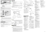
For details on how to use the program pattern setup chart, see “1. Overview of Program Patterns” and “2. Examle of Program Pattern Setup Charts” in Programming User’s Manual .
You can register as many as 30 program patterns with the UP550 controller. Create as many copies of the chart as necessary.
First fill in the fields with bold-face borders in the order from number 1 to number 9. Then, input the data into the controller.
1.
2.
3.
4.
5.
6.
7.
8.
9.
3rd Edition: Sep 30, 2004
Maximum value of PV input range: Setpoint of the “Maximum Value of PV Input Range (RH1)” setup parameter
Minimum value of PV input range: Setpoint of the “Minimum Value of PV Input Range (RL1)” setup parameter
PV input unit: Setpoint of the “PV Input Unit (UNI1)” setup parameter
Program time unit: Setpoint of the “Program Time Unit (TMU)” setup parameter
Segment setting method: Setpoint of the “Segment Setting Method (SEG.T)” setup parameter
Starting target setpoint: Setpoint of the “Starting Target Setpoint (SSP1)” program parameter
Start code: Setpoint of the “Start Code (STC)” program parameter
Final target setpoint, Segment time, Events (PV event and Time event), and Junction code: Setpoint of each program parameter
Draw the program pattern.
This manual briefly explains the functions of program parameters. In addition, it contains a program pattern setup chart. Completely fill in the
chart before you set a program in the UP550 program controller.
Define this parameter when using the controller as a program pattern
generator.
See User’s Manual (Reference) (CD-ROM version) for
more information.
6
Starting target setpoint 1 (SSP1)
Starting target setpoint 2 (SSP2)
7
Start code (STC)
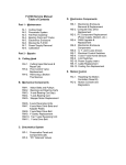
Contents
1st group of wait zones (1.WZ1)
1st group of wait times (1.WTM)
1. Program Pattern Setup Charts
2. Program Parameter Map
3. Lists of Program Parameters
4. Explanation of Program Functions
2nd group of wait zones (2.WZ1)
2nd group of wait times (2.WTM)
3rd group of wait zones (3.WZ1)
3rd group of wait times (3.WTM)
See User’s Manual (Reference) (CD-ROM version) for
more information.
4th group of wait zones (4.WZ1)
4th group of wait times (4.WTM)
5th group of wait zones (5.WZ1)
System name
5th group of wait times (5.WTM)
Program No.
Program name
UP550 -
Model
Program time unit (TMU)
4
Number of repetitions (RCY)
Segment setting method (SEG.T)
5
Start-of-repetition segment number (RST)
End-of-repetition segment number (REN)
Serial No.
9
3
Unit
Maximum value of PV input range (RH1) 1
100%
Minimum value of PV input range (RL1) 2
0%
Define this parameter when using
the controller as a program pattern
generator. See User’s Manual
(Reference) (CD-ROM version)
for more information.
1
Segment No.
2
3
4
5
6
7
8
9
10
11
12
13
14
15
16
17
18
19
20
Final target setpoint 1 (TSP1)
Final target setpoint 2 (TSP2)
Segment time (TIME/TM.RT)
PID number (PID)
Event number (EV1)
Time setting (TIME) when the
Segment Setting Method
(SEG.T) parameter is set as
SEG.T = 0; ramp setting
(TM.RT) when the parameter
is set as SEG.T = 1
Factory-set to Time setting
(TIME).
PV event type (TY1)/on time of time event (ON1)
PV event setpoint (PE1)/off time of time event (OFF1)
Event number (EV2)
PV event type (TY2)/on time of time event (ON2)
PV event setpoint (PE2)/off time of time event (OFF2)
Event number (EV3)
PV event type (TY3)/on time of time event (ON3)
Shown for segment PID
parameters when the setup
parameter “ZON” is set to 0.
PV event setpoint (PE3)/off time of time event (OFF3)
Event number (EV4)
PV event type (TY4)/on time of time event (ON4)
8
PV event setpoint (PE4)/off time of time event (OFF4)
Event number (EV5)
PV event type (TY5)/on time of time event (ON5)
PV event setpoint (PE5)/off time of time event (OFF5)
Event number (EV6)
PV event type (TY6)/on time of time event (ON6)
PV event setpoint (PE6)/off time of time event (OFF6)
Event number (EV7)
PV event type (TY7)/on time of time event (ON7)
PV event setpoint (PE7)/off time of time event (OFF7)
Event number (EV8)
PV event type (TY8)/on time of time event (ON8)
PV event setpoint (PE8)/off time of time event (OFF8)
Junction code (JC)
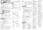
2.
Program Parameter Map
Operating display
SET/ENT
key
Press this key for more than
3 seconds.
Press the
key
for more than
3 seconds to switch
to an operating
display.
SET/ENT
PROG
programming
main menu
SET/ENT
key
DISP
key
Program Parameter Setting Display
key or
key
A
LOC
key or
local mode set
key
PRG
key or
SET/ENT
EDIT
key
programming
program edit
sub menu
key
DISP
key
sub menu
sub menu
SET/ENT
SET/ENT
key
DISP
key
Program pattern 1
LSP1
Setpoint for
local-mode operation
PID
PID group number for
local-mode operation
E21A
Local event-21
type
E21B
Local event-21
setpoint
E22A
Local event-22
type
MENU:PROG/PRG
PTno. input
PTN
SET/ENT
Local event-22
setpoint
E23A
Local event-23
type
E23B
Local event-23
setpoint
E24A
Local event-24
type
E24B
Local event-24
setpoint
E25A
Local event-25
type
E25B
Local event-25
setpoint
E26A
Local event-26
type
E26B
Local event-26
setpoint
key or
SEG
MENU:PROG/PRG
PTno. input
key
1
MENU:PROG/PRG
SEGno. input
PTN
=
#2
key or
key
0
MENU:PROG/PRG
SEGno. input
SEG
SET/ENT
key
=
key
Segment 2
#2
key or
MENU:PROG/PRG
SEGno. input
key
1
SEG
SET/ENT
key
=
or
#2
key
2
MENU:PROG/PRG
SEGno. input
SEG
SET/ENT
key
key
Segment 3
=
or
key
or
#2
key
3
key
MENU:PROG/PRG
SEGno. input
SET/ENT
=
Starting target
setpoint
TSP1
Final target setpoint
TIME
Time-set
segment time
TR.RT
Ramp-set
segment time
PID
PID group number
STC≠ –1
STC
Start code
#2
99
MENU:PROG/PRG
SEGno. input
SEG
=
#2
“TIME” is shown when the Segment
Setting Method (SEG.T) parameter
is set using a time setpoint; “TM.RT”
is shown when the Segment Setting
Method (SEG.T) parameter is set
using a ramp grade setpoint.
The controller is factory-set to
show “TIME”.
PTN.S
key
ALL.E
Shows the number of
remaining unused
events.
COPY
Program pattern
copying
CLEAR
Program pattern
clearance
0
TSP1
Final target setpoint
TSP1
Final target setpoint
TSP1
Final target setpoint
TIME
Time-set
segment time
TIME
Time-set
segment time
TIME
Time-set
segment time
TR.RT
Ramp-set
segment time
TR.RT
Ramp-set
segment time
TR.RT
Ramp-set
segment time
PID
PID group number
PID
PID group number
PID
PID group number
EVn
Event number
EVn
Event number
EVn
Event number
ONn
On time of
time event
ONn
On time of
time event
ONn
On time of
time event
The parameter “PID” is shown for
segment PID parameters when the
setup parameter “ZON” is set to 0.
STC= –1
EVn
Event number
E27A
Local event-27
type
1.WTM
1st group of
wait times
ONn
On time of
time event
E27B
Local event-27
setpoint
2.WZ1
2nd group of
wait zones
OFFn
Off time of
time event
OFFn
Off time of
time event
OFFn
Off time of
time event
OFFn
Off time of
time event
E28A
Local event-28
type
2.WTM
2nd group of
wait times
TYn
PV event type
TYn
PV event type
TYn
PV event type
TYn
PV event type
E28B
Local event-28
setpoint
3.WZ1
3rd group of
wait zones
PEn
PV event setpoint
PEn
PV event setpoint
PEn
PV event setpoint
PEn
PV event setpoint
3.WTM
3rd group of
wait times
4.WZ1
4th group of
wait zones
4.WTM
4th group of
wait times
JC
Junction code
JC
Junction code
JC
Junction code
JC
Junction code
5.WZ1
5th group of
wait zones
5.WTM
5th group of
wait times
RCY
Number of
repetitions
RST
Start-of-repetition
segment number
REN
End-of-repetition
segment number
SET/ENT
IM 05E01C02-04E (1)
SET/ENT
n = 1 to 8.
If EVn = 1 to 16, then this parameter
refers to time events 1 to 16.
If EVn = 21 to 28, then this parameter
refers to PV events 1 to 8.
SET/ENT
key
key
Parameters of program pattern 1
key
SET/ENT
key
Shows the number of
remaining unused
segments.
Shows the number of
segments within
a pattern.
key
1st group of
wait zones
The parameter “PID” is shown for segment
PID parameters when the setup parameter
“ZON” is set to 0.
key
key
or
1.WZ1
key
ALL.S
2
Segment 99
SEG
key
=
#1
SET/ENT
SSP1
DISP
Program pattern 2
#1
Segment 1
SET/ENT
E22B
=
key
Pressing the DISP key once during programming
returns to the display marked A .
key
These parameter symbols
appear on the PV display.