1
3. Changing PV Input Type
4. Setting Control Output Type (except for a Position Proportional Controller)
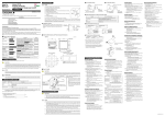
The following operating procedure describes an example of changing PV input terminal
the setting of K-type thermocouple (-200.0 to 500.0⬚C) to RTD Pt100 Thermocouple/mV/V input.............................. 12 - 13
(-200.0 to 500.0⬚C) and a measurement range of 0.0 to 200.0⬚C.
RTD input .................................................. 11 - 12 - 13
The following operating procedure describes an ex- Control output terminal Values in parentheses are setpoints
ample of changing time proportional PID relay out- Time proportional PID relay (0)/on-off(3) output........................... 1 - 2 - 3
put (0: factory-set default) to current output (2).
Current (2)/time proportional PID voltage pulse (1) output............. 16 - 17
For details on the output terminals for heating/cooling control, see “6.
Terminal Wiring Diagrams ” in Installation User’s Manual .
1.
Bring the operating display into view (display appears at power-on)
PV2
RST lamp
ON.
PV
1.
Bring the operating display into view (display appears at power-on).
PVE1
PVE2
PV2
TME
1
2
3
4
AL
1
PRG
RST
HLD
LOC
MAN
CAS
SET/ENT
MODE
PT.No
SP:
DISP
RUN
0.0°C
PTNO: 0
TM=-------
RESET
RST lamp
ON.
SET/ENT
Press the
key for more than 3 seconds to call
up the main menu “PROG”.
10.
Press the
PVE2
AL
1
PRG
RST
HLD
LOC
MAN
CAS
SET/ENT
programming
main menu
MODE
SP:
DISP
RUN
IN1
SET/ENT
Press the
key for more than 3 seconds to call
up the main menu “PROG”.
SETUP
Pt2
=
MODE
PT.No
SET/ENT
DISP
RUN
MODE
RUN
7.
Press the
“OUT”.
PROG
Press the
“STUP”.
key once to display the main menu
11.
Press the
“UNI1”.
SET/ENT
password input
main menu
MODE
MODE
PT.No
4.
SET/ENT
UNI1
SET/ENT
#2
SETUP
°C
=
MODE
12.
SET/ENT
RUN
MODE
PT.No
RUN
5.
Press the
“UPMD”.
RH1
SET/ENT
8.
MODE
PT.No
RH1
SET/ENT
DISP
RUN
OT1
SET/ENT
RUN
Press the
“MD”.
SET/ENT
RUN
MODE
Press the
MODE
PT.No
MODE
9.
RH1
SET/ENT
RUN
PT.No
7.
MODE
RUN
#1
SET/ENT
MODE
OT1
RUN
SET/ENT
RUN
MODE
RUN
MODE
V.AT
SET/ENT
#1
changing!
ON
=
MODE
RESET
10.
5.
Press the
“UPMD”.
key once to display the main menu
10.
Press the
SET/ENT
RUN
Press the
“STUP”.
SET/ENT
SET/ENT
RESET
MODE
OT1
SET/ENT
DISP
RUN
#1
Press the
“UPMD”.
RUN
MODE
V.AT
SET/ENT
DISP
RUN
key once to display the main menu
Press the
“MD”.
MODE
4.
Press the
“PARA”.
#1
MODE
SET/ENT
11.
RUN
RESET
SET/ENT
RUN
MENU:UPMD/VALV
valve auto tuning
V.AT
MODE
RUN
MODE
SET/ENT
DISP
RUN
RL1
=
5.
Press the
“UPMD”.
MODE
MODE
IN1
Press the
“MD”.
SET/ENT
key once to display the submenu
12.
SET/ENT
MODE
PT.No
#1
RUN
Press the
SET/ENT
key for more than 3 seconds. This returns you to the display shown at power-on (figure below).
PV2
MENU:UPMD/VALV
valve auto tuning
V.AT
SET/ENT
MODE
RL1
DISP
RST lamp
ON.
7.
PVE1
PVE2
TME
1
2
3
4
PRG
RST
HLD
LOC
MAN
CAS
SET/ENT
MODE
PT.No
#4
changing!
0.0
=
MODE
RESET
=
6.
Press the
“MD”.
MENU:UPMD/IN
input 1 type select
IN1
SET/ENT
MODE
PT.No
Press the
DISP
RUN
SET/ENT
RUN
SP:
DISP
MODE
Blinks during
change
DISP
PT.No
RUN
RESET
10.
SET/ENT
Press the
key once. The display momentarily
becomes blank (which is normal), indicating the
parameters have been initialized.
MENU:UPMD/INIT
Parameter initialize
INI
#1
SETUP
ON
=
MODE
SET/ENT
SET/ENT
DISP
RUN
MODE
DISP
PT.No
RESET
RUN
RESET
key once to display the submenu
UP mode set
SETUP sub menu
SETUP
ERR
RUN
MODE
PT.No
DISP
RUN
RESET
RESET
RUN
RESET
11.
SET/ENT
key for more than 3 seconds. This returns you to the display shown at power-on (figure below).
RST lamp
ON.
valve control
SETUP sub menu
SEGNO: 0/ 0
RCY: 0/ 0
Press the
PV2
VALV
0.0°C
PTNO: 0
TM=-------
● List of Control Output Types
Parameter
Symbol
Name of Parameter
Blinks during
change.
Setpoint
0
1
2
3
RESET
MODE
PT.No
Control Output Types
Time proportional PID relay contact output (terminals 1 - 2 - 3 )
Time proportional PID voltage pulse output (terminals 16 - 17 )
Current output (terminals 16 - 17 )
On/off control relay contact output (terminals 1 - 2 - 3 )
The following 4 to 12 are displayed only for heating/ cooling type controllers.
key once to register the setpoint.
MENU:UPMD/IN
input 1 range low
RL1
Blinks during
change.
RESET
#4
SETUP
0.0
=
SET/ENT
DISP
RUN
=
RESET
PV
PVE1
PVE2
TME
1
2
3
4
AL
1
PRG
RST
HLD
LOC
MAN
CAS
MODE
DISP
PT.No
RUN
MODE
PT.No
OT1
#1
changing!
Pt2
=
17.
#1
changing!
ON
MD
#1
Press the
key three times to display the
submenu “VALV”.
SET/ENT
DISP
PT.No
Press the
or
key to display the required
setpoint. The figure below shows an example of
setting the PV input type to a Pt100 resistance
temperature detector (-200.0°C to 500.0°C).
key to display “ON”.
SET/ENT
UP550 configuration
SETUP main menu
DISP
13.
Press the
SET/ENT
DISP
RUN
Control output type
4
5
6
7
8
9
10
11
12
SP:
DISP
RUN
RESET
PTNO: 0
TM=-------
0.0°C
SEGNO: 0/ 0
RCY: 0/ 0
RESET
key for more than 3 seconds. This returns you to the display shown at power-on (figure below).
PRG lamp or
LOC lamp ON.
PV2
PV
PVE1
PVE2
TME
1
2
3
4
AL
1
PRG
RST
HLD
LOC
MAN
CAS
SET/ENT
9.
RESET
PV
RESET
MENU:UPMD/IN
input 1 range low
SET/ENT
RUN
Press the
UPMD
SET/ENT
Calibration has ended unsuccessfully if the
indication changes from “ON” to “ERR”.
Check the feedback input wiring and carry out
automatic calibration again.
UP mode set
SETUP sub menu
RESET
#4
Press the
or
key to display the required
setpoint. The figure below shows an example of
setting the minimum value of the PV input range to
0.0°C.
SETUP
typeK3
=
9.
INI
SET/ENT
MENU:UPMD/IN
input 1 type select
RUN
MENU:UPMD/INIT
parameter initialize
#1
SETUP
OFF
PT.No
DISP
DISP
PT.No
RESET
16.
DISP
PT.No
key once to display the main menu
SET/ENT
11.
SETUP
-200.0
=
SET/ENT
DISP
SET/ENT
MODE
RESET
RESET
MD
MENU:UPMD/IN
input 1 range low
Press the
key once to display the parameter
“IN1” (PV input type).
=
DISP
UP mode set
SETUP sub menu
1
8.
#1
SETUP
OFF
RESET
Go to step 13.
MD
RUN
key once to display the parameter
INI
key once to display the main menu
SET/ENT
Calibration has ended successfully when the
indication changes from “ON” to “OFF”.
UP550 configuration
SETUP main menu
6.
MODE
SET/ENT
MENU:UPMD/INIT
parameter initialize
setup parameter
SETUP main menu
DISP
PT.No
key once to display the submenu
SET/ENT
Press the
“INI”.
PARA
DISP
#3
RESET
8.
password input
main menu
SETUP
ON
=
RESET
key once to display the main menu
PT.No
SET/ENT
RESET
RESET
MENU:UPMD/VALV
valve auto tuning
UPMD
SETUP
2
=
PT.No
RESET
RUN
key once to register the setpoint.
5.
UP550 configuration
SETUP main menu
DISP
PT.No
STUP
Blinks
during change.
Press the
key once. The controller
automatically calibrates the valve position (fully open
or closed).
setup parameter
SETUP main menu
RESET
MENU:UPMD/OUT
output 1 select
UPMD
MODE
RESET
SET/ENT
PARA
Blinks during
change.
RUN
DISP
PT.No
key once to display the main menu
SET/ENT
DISP
DISP
PT.No
RESET
Press the
“PARA”.
parameter initialize
SETUP sub menu
RESET
MENU:UPMD/VALV
valve auto tuning
#1
changing!
2
=
4.
key twice to display the submenu
INIT
programming
main menu
PT.No
SET/ENT
Press the
“INIT”.
key to display “ON”.
DISP
RUN
7.
PROG
3.
RESET
MENU:UPMD/OUT
output 1 select
AL
RUN
9.
SEGNO: 0/ 0
RCY: 0/ 0
DISP
PT.No
Press the
0.0°C
PTNO: 0
TM=-------
RESET
SET/ENT
input set
SETUP sub menu
PT.No
MODE
RESET
RUN
SET/ENT
SETUP
OFF
=
SP:
DISP
Press the
key for more than 3 seconds to call
up the main menu “PROG”.
PT.No
Blinks during
change.
Press the
key once to display the parameter
“RL1” (minimum value of PV input range).
IN
MODE
RUN
key once to display the main menu
PT.No
SET/ENT
SET/ENT
DISP
password input
main menu
DISP
PT.No
15.
MODE
PT.No
SETUP
200.0
=
RESET
key once to display the submenu “IN”.
2.
V.AT
MODE
In steps 2 and later, illustrations of the LCD are cited to explain the procedure.
key once to display the parameter
MENU:UPMD/VALV
valve auto tuning
STUP
Press the
or
key to display the required
setpoint. The figure below shows an example of
setting to current output (4 to 20 mA DC).
DISP
PT.No
Press the
3.
Press the
“STUP”.
key once to register the setpoint.
DISP
RUN
SET/ENT
DISP
PT.No
PRG
RST
HLD
LOC
MAN
CAS
PT.No
PT.No
#1
#3
MENU:UPMD/IN
input 1 range high
UP mode set
SETUP sub menu
SET/ENT
SET/ENT
MODE
RESET
key once to display the main menu
SET/ENT
6.
MD
SET/ENT
SETUP
0
=
1
2
3
4
SET/ENT
DISP
PT.No
14.
RESET
RESET
changing!
200.0
=
RESET
key once to display the submenu
SEGNO: 0/ 0
RCY: 0/ 0
SET/ENT
SET/ENT
PT.No
6.
Press the
“V.AT”.
programming
main menu
Press the
key once to display the parameter
“OT1” (control output type).
setup parameter
SETUP main menu
MENU:UPMD/IN
input 1 range high
UP550 configuration
SETUP main menu
8.
PROG
PT.No
Press the
“PARA”
DISP
Press the
or
key to display the required
setpoint. The figure below shows an example of
setting the maximum value of the PV input range to
200.0°C.
UPMD
SET/ENT
MODE
PT.No
13.
RUN
MENU:UPMD/OUT
output 1 select
SETUP
500.0
=
RESET
key once to display the main menu
PTNO: 0
TM=-------
RESET
PVE2
TME
1
SET/ENT
DISP
PT.No
4.
#3
MODE
PV
PVE1
AL
RESET
MENU:UPMD/IN
input 1 range high
DISP
RUN
0.0°C
DISP
PT.No
PARA
SET/ENT
MODE
RESET
key once to display the main menu
SET/ENT
setup parameter
SETUP main menu
RUN
SET/ENT
output set
SETUP sub menu
STUP
Press the
key once to display the parameter
“RH1” (maximum value of PV input range).
PARA
DISP
Press the
key for more than 3 seconds to call
up the main menu “PROG”.
DISP
PT.No
RESET
key once to display the main menu
MODE
.SP:
L
SET/ENT
3.
Press the
“STUP”.
SET/ENT
Press the
“PARA”.
2.
PT.No
DISP
RUN
SET/ENT
RST lamp
ON.
In steps 2 and later, illustrations of the LCD are cited to explain the procedure.
OUT
password input
main menu
SET/ENT
1
key twice to display the submenu
DISP
PT.No
key once to display the parameter
MENU:UPMD/IN
input 1 unit select
STUP
PV2
PRG
RST
HLD
LOC
MAN
CAS
RESET
SET/ENT
3.
Bring the operating display into view (display appears at power-on).
PVE2
AL
MAN lamp
ON.
SEGNO: 0/ 0
RCY: 0/ 0
DISP
PT.No
RESET
Initializing the above parameter setpoints may initialize the registered operating/setup parameter setpoints. Check
that they are correct. If any of them has been changed to its initial value, set it to a required value.
1.
PV
In steps 2 and later, illustrations of the LCD are cited to explain the procedure.
2.
#1
CAUTION
PVE1
1
2
3
4
0.0°C
PTNO: 0
TM=-------
RESET
programming
main menu
SET/ENT
PV2
PT.No
key once to register the setpoint.
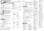
6. Initializing Parameters
Be sure to follow the steps below after a change of setting has been made to the data item PV Input Type, PV Input Range or
PV Input Scale.
TME
PT.No
MENU:UPMD/IN
input 1 type select
PROG
PRG lamp or
LOC lamp ON.
PVE1
1
2
3
4
(for a Position Proportional Controller Only)
Bring the operating display into view (display appears at power-on).
TME
SEGNO: 0/ 0
RCY: 0/ 0
SET/ENT
1.
PV
In steps 2 and later, illustrations of the LCD are cited to explain the procedure.
2.
5. Calibrating Valve Position
The following operation describes a procedure of inputting a feedback signal from a control valve to calibrate the full closed and full
open positions of the valve automatically. To calibrate the valve position, you need to carry out wire connections and bring the controller
into manual mode. For connections, see “6. Terminal Wiring Diagrams” in Installation User’s Manual and for entering the manual
mode, see “6. Switching between AUTO and MAN” in Operations User’s Manual .
If the controller is in RESET mode, you need to bring the controller into program operation (RUN) or local operation (LOCAL). For
entering the program operation, see “5. Switching between RUN and RESET Modes” in Operations User’s Manual , and entering
the local operation, see “11, Switching to Local-mode (LOCAL) Operation” in Operations User’s Manual
MODE
PT.No
.SP:
L
DISP
RUN
RESET
PTNO: 0
TM=-------
0.0°C
SEGNO: 0/ 0
RCY: 0/ 0
Heating-side relay output (terminals 1 - 2 - 3 ), cooling-side relay output (terminals 48 - 49 - 50 )
Heating-side pulse output (terminals 16 - 17 ), cooling-side relay output (terminals 48 - 49 - 50 )
Heating-side current output (terminals 16 - 17 ), cooling-side relay output (terminals 48 - 49 - 50 )
Heating-side relay output (terminals 1 - 2 - 3 ), cooling-side pulse output (terminals 46 - 47 )
Heating-side pulse output (terminals 16 - 17 ), cooling-side pulse output (terminals 46 - 47 )
Heating-side current output (terminals 16 - 17 ), cooling-side pulse output (terminals 46 - 47 )
Heating-side relay output (terminals 1 - 2 - 3 ), cooling-side current output (terminals 46 - 47 )
Heating-side pulse output (terminals 16 - 17 ), cooling-side current output (terminals 46 - 47 )
Heating-side current output (terminals 16 - 17 ), cooling-side current output (terminals 46 - 47 )
RESET
If the type of Input is voltage, also configure
the PV Input Decimal Point Position (SDP1),
Maximum Value of PV Input Scale (SH1), and
Minimum Value of PV Input Scale (SL1)
parameters that follow this step.
18.
Press the
SET/ENT
key for more than 3 seconds. This returns you to the display shown at power-on (figure below).
PV2
RST lamp
ON.
PV
PVE1
PVE2
TME
1
2
3
4
AL
1
PRG
RST
HLD
LOC
MAN
CAS
SET/ENT
MODE
PT.No
SP:
DISP
RUN
RESET
PTNO: 0
TM=-------
0.0°C
SEGNO: 0/ 0
RCY: 0/ 0
IM 05E01C02-02E (2)