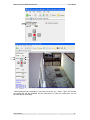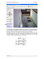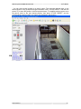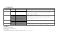
1
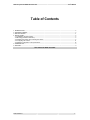
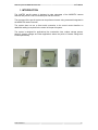
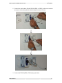
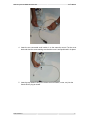
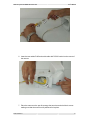
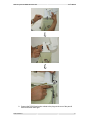
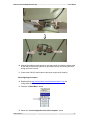
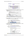
PAN-TILT MOTOR
for
MOBOTIX cameras M1, M10, M12
User’s Manual V03_EN
2007
PAN-TILT system for MOBOTIX cameras V03
User’s Manual
Table of Contents
1. INTRODUCTION..................................................................................................................................................... 2
2. PACKAGE CONTENT ............................................................................................................................................ 3
3. SPECIFICATIONS .................................................................................................................................................. 4
4. INSTALLATION....................................................................................................................................................... 5
4.1 Establishing the best location............................................................................................................................ 5
4.2 Mounting (hardware installation) ....................................................................................................................... 5
4.3 Installing the camera and connecting the cables.............................................................................................. 5
4.4 Configuring the camera ................................................................................................................................... 11
4.5 Software configuration of the pan-tilt motor .................................................................................................... 13
5. COMMAND SET ..................................................................................................................................................... 0
6. SUPPORT ............................................................................................................................................................... 0
This manual is dated June 2007
www.mobotix.ro
1
PAN-TILT system for MOBOTIX cameras V03
User’s Manual
1. INTRODUCTION
The LANTEC pan-tilt system is designed to take advantage of the MOBOTIX camera
features and provide a low cost outdoor pan and tilt functions.
The command of the pan-tilt system can be performed remote using commands integrated in
the MOBOTIX camera’s screen.
The system does not use a direct serial connection to the control center therefore no
additional cabling is required for the control of the pan-tilt system.
The system is designed for applications like construction sites, outdoor storage spaces,
harbors, airports, garages and other applications where the points of interest change their
location periodically.
www.mobotix.ro
2
PAN-TILT system for MOBOTIX cameras V03
User’s Manual
2. PACKAGE CONTENT
The items that you will identify upon opening the package are shown below. When
you open the equipment package, make sure using this list of items, that you received the full
content.
•
Pan-tilt motor
•
Serial cable with RS-232 outlet to
connect to the camera
•
Serial cable with RS-232 outlet to
connect to the motor
•
Power cord (230VAC)
•
Screws to install the camera on
the pan-tilt motor
(A)
(B)
(C)
(D)
(E)
www.mobotix.ro
3
PAN-TILT system for MOBOTIX cameras V03
User’s Manual
3. SPECIFICATIONS
Pan-tilt Motor:
Input voltage:
AC 24V/220V 50Hz
Angular level:
Pan 350°
Tilt +20° ~ -90°
Speed:
Pan 6°/sec.
Tilt 3°/sec.
Limit stop:
Mechanically adjustable
Load rating:
15 Kg.
Operating temperature:
-35°C ~ +60°C
Construction:
Aluminum alloy casting
Dimensions (mm.):
225(L) X 180(W) X 260(H)
Pan-tilt Interface:
Location
Operating
temperature:
Control mode:
Compatibility:
Control:
Commands:
Included in the motor’s housing
-35°C ~ +60°C
Solid state switching (no relays)
Compatible with all MOBOTIX cameras M1, M10 and M12 (except the
“basic” and “web” versions)
Control via RS-232 interface of the camera using soft buttons and LANTEC
pan-tilt configurator
UP – cancels any other eventual movement and moves the camera
upwards until the mechanical limit is reached or the STOP button is
pressed.
DOWN – cancels any other eventual movement and moves the camera
downwards until the mechanical limit is reached or the STOP button is
pressed.
LEFT – cancels any other eventual movement and moves the camera left
until the mechanical limit is reached or the STOP button is pressed.
RIGHT – cancels any other eventual movement and moves the camera
right until the mechanical limit is reached or the STOP button is pressed.
STOP – stops any performing movement of the camera.
Preset 1…20 – Moves the motor to the position stored under the current
preset no.
Store Preset – When pressed, the following press of a “Preset” button,
stores the current position into the corresponding preset no.
www.mobotix.ro
4
PAN-TILT system for MOBOTIX cameras V03
User’s Manual
4. INSTALLATION
In order to ensure the proper operation of the equipment please follow the following
steps:
• Establish the best location
• Mounting (Hardware installation)
• Installing the camera and connecting the cables
• Configuring the camera
• Software configuration of the pan-tilt motor
4.1 Establishing the best location
In order to determine the best location for the pan-tilt system, please consider the
following:
•
If you use wired connections, the length of the Ethernet cables that connects the
MOBOTIX camera to the network must not exceed 100 meters.
•
For power supply, use only a reliable 230 VAC connection secured of accidental
over-voltages and lightning.
•
Make sure that during the complete range of rotation and tilt the assembly does not
touch any structure near the pan-tilt system. The rotating force of the motor is very
high and important damages may occur if the moving assembly touches any fixed
structures while in motion.
4.2 Mounting (hardware installation)
The pan-tilt system will be mounted horizontally, by means simply placing it on a flat
surface and securing it with 4 screws.
The surface must be level and strong enough to hold the weight of the pan-tilt system
together with its cables and camera.
4.3 Installing the camera and connecting the cables
1. Unscrew the bottom screw and remove the cover.
www.mobotix.ro
5
PAN-TILT system for MOBOTIX cameras V03
User’s Manual
2. Connect the serial cable (B) with RS-232 (DB-9 or DB-15) outlet to the camera
and secure it; then that pass the cable through the camera’s mount.
3. Connect the RS-232 (DB-9 or DB-15) plugs as shown.
www.mobotix.ro
6
PAN-TILT system for MOBOTIX cameras V03
User’s Manual
4. Insert the two connected serial outlets in to the camera’s mount. Put the cover
back and wind the screw making sure that the cover is well positioned in its place.
5. Insert the two cables RJ45 (from camera and from switch, router, etc) into the
female RJ-45 plug as shown.
www.mobotix.ro
7
PAN-TILT system for MOBOTIX cameras V03
User’s Manual
6. Insert the two cables RJ45 and serial cable with RS-232 outlet into the mount of
the camera.
7. Place the camera on the pan-tilt, arrange the two wires and wind the 4 screws
making sure that the mount is well positioned in its place.
www.mobotix.ro
8
PAN-TILT system for MOBOTIX cameras V03
User’s Manual
8. Connect the RS-232 and mains outlets to the plugs at the rear of the pan-tilt
motor and screw them tight.
www.mobotix.ro
9
PAN-TILT system for MOBOTIX cameras V03
User’s Manual
9. Set the mechanical limits (clipper) of the pan-tilt motor to match the desired range
of movement.
www.mobotix.ro
10
PAN-TILT system for MOBOTIX cameras V03
User’s Manual
10. Arrange the cables to make sure they are long enough to match the whole range
of pan and tilt without being broken or get stocked in any surrounding structure
during the motor’s motion.
11. Connect the 230VAC mains cable to the power supply at the location.
4.4 Configuring the camera
12. Download from http://www.mobotix.ro/ro/firmware/pantilt-m12.zip the
configuration file and save it in your computer:
13. Press the “Admin Menu” button:
14. Select the “Load configuration from local computer” option
www.mobotix.ro
11
PAN-TILT system for MOBOTIX cameras V03
User’s Manual
15. Select the location where you downloaded the configuration file on your computer
and then press “Upload” button, after you extract pantilt-m12.cfg from
pantilt-m12.zip:
16. From the “Replace” drop-down menu select the “Everything except the parts
checked below” option and press the “Merge” button:
17. Uncheck the sections “Page (language, soft buttons, multi view” and “Serial
Interface (modem, data)”
www.mobotix.ro
12
PAN-TILT system for MOBOTIX cameras V03
User’s Manual
18. Store the configuration into flash and then reboot the camera
4.5 Software configuration of the pan-tilt motor
19. Set the duration of pan-tilt movement (seconds), horizontal range (degrees),
vertical range (degrees) by connecting to http://www.mobotix.ro/pan-tilt and select
the desired limits. After that you can store from 1 to 24 preset into the camera.
Attention: The pan-tilt must be configured so as to move inside the
mechanical limits (clippers).
The mechanical limits (clippers) of the pan-tilt are shown in the images above. The pan-tilt
can move horizontal or to the vertical.
In order to configure the pan-tilt you must follow these steps:
- make sure that the pan-tilt does not hit anything while rotating on horizontally and vertically.
- type http://www.mobotix.ro/pan-tilt in a web browser.
- Type the camera’s address in the "MOBOTIX camera" box. If you don’t set any port, it will
start by default on the port 80.
www.mobotix.ro
13
PAN-TILT system for MOBOTIX cameras V03
User’s Manual
- before performing any command, if you press one of the, “up”, ‘”down”, “right”, ”left” arrows,
the camera will ask the password and the username of it. After you insert them you can
proceed with the next steps.
www.mobotix.ro
14
PAN-TILT system for MOBOTIX cameras V03
User’s Manual
- to establish the length of movement vertically or horizontally, type in the “Duration” box the
duration you wish. This will be written in seconds, as for instance 0.5 meaning half a second,
2 meaning 2 seconds.
- the next step you must calibrate the pan-tilt. After you press "CALIBRATE", the pan-tilt will
rotate horizontally to the left until it reaches the mechanical clipper (a complete rotation takes
1 minute), and then will move vertically down until the mechanical clipper (the complete
movement takes 30 seconds).
www.mobotix.ro
15
PAN-TILT system for MOBOTIX cameras V03
User’s Manual
- The next step is establishing the vertical and horizontal limits (down and across).
Considering that you have already established the mechanical limits of the pan-tilt now you
can also establish the software limits. These will be set so as through the vertical or
horizontal movement the pan-tilt not touch the mechanical limits you set before.
For instance if you insert “180” degrees in the "Horizontal range" box, the pan-tilt will rotate
horizontally 180 degrees. If you insert “90” degrees in the "Vertical range" box, the pan-tilt
will rotate vertically 90 degrees. In this example, the mechanical limits must allow
movements of minimum 190° horizontally and 100° vertically.
www.mobotix.ro
16
PAN-TILT system for MOBOTIX cameras V03
User’s Manual
- You can store several presets to a pan-tilt motor. First move the pan-tilt motor to the
desired position using up-down-left-right commands. Press "STORE PRESET" and then the
preset "01" to store the position in the first preset memory. To establish another preset, move
the pan-tilt motor to the next desired position, then press "STORE PRESET" and the
corresponding preset’s number you want to be registered in that position.
www.mobotix.ro
17
5. COMMAND SET
Command set
Command
MXL packet
Comments
Move calibrate
Down left
8X 01 06 00 03 00 00 FF
Set limits
Horizontal
Vertical
8X 01 06 00 10 0G GG FF
8X 01 06 00 11 0G GG FF
Move absolute
Stop
Up
Down
Left
Right
Duration
Up
Down
Left
Right
Store
Preset
8X
8X
8X
8X
8X
8X
8X
8X
8X
8X
8X
8X
Move duration
Preset strings
01
01
01
01
01
01
01
01
01
01
01
01
06
06
06
06
06
06
06
06
06
06
06
06
01
01
01
01
01
01
02
02
02
02
03
03
00
01
02
03
04
10
01
02
03
04
00
01
FF
FF
FF
FF
FF
TT
TT
TT
TT
TT
FF
PP
TT
TT
TT
TT
TT
FF
FF
FF
FF
FF
FF
Sets the absolute limits of vertical and horizontal movement from
origin in degrees. 0G GG is from 00 00 to 03 50 horizontal and
from 00 00 to 00 90 vertical. Time conversion to degrees:
Horizontal: 180° = 30seconds
Vertical: 45° = 15seconds
No more than one output active at a time
A new command stops the previous.
The movement is as long as the duration TT TT set with the
“Duration command” from 00 01 to 99 99 in 1/10 seconds. Default
value of duration is 1 second.
TT TT time from 00 01 to 99 99 in 1/10 seconds
PIC does not execute a command before completion of the previous.
PP preset position no. (from 01 to 24). As long as any movement
is active, no preset or store commands are accepted.
8X = Header
01 = com mode
06 = categ mode (movement)
Message = UU VV, TT TT, GG GG, PP
FF = Terminator
The commands will be sent without any spaces (ex. Duration 14.6 sec is 8X010601100146FF)
6. SUPPORT
For technical support contact:
LANTEC ROMANIA
Str. Ing. V. Cristescu 17
021984 Bucharest
ROMANIA
Tel: +40(21)3204707
Fax: +40(21)3028903
GSM: +40(749)054444
Email: [email protected]