1
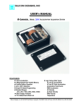
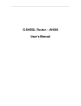
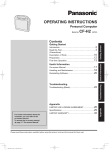
He/O2 Analyzer User’s Manual ON OFF MENU CAL MODE ESC He/O2 Analyzer July 2012, EN Content Safety warning . . . . . . . . . . . . . . . . . . . . . . . . . . . . . . . . . . . . . . . . . . . . . . . . . . . . . . . 5 1. About firmware and hardware versions . . . . . . . . . . . . . . . . . . . . . . . . . . . . . . . . . . 6 2. Measuring principle . . . . . . . . . . . . . . . . . . . . . . . . . . . . . . . . . . . . . . . . . . . . . . . 7 3. Description of the analyzer . . . . . . . . . . . . . . . . . . . . . . . . . . . . . . . . . . . . . . . . . . 8 4. Operating the analyzer . . . . . . . . . . . . . . . . . . . . . . . . . . . . . . . . . . . . . . . . . . . . . 9 5. Measuring O2 and He concentration . . . . . . . . . . . . . . . . . . . . . . . . . . . . . . . . . . . 10 6. Display modes . . . . . . . . . . . . . . . . . . . . . . . . . . . . . . . . . . . . . . . . . . . . . . . . . . . 11 6.1 Calibration of the oxygen sensor . . . . . . . . . . . . . . . . . . . . . . . . . . . . . . . . . . . . . 13 7. Other functions . . . . . . . . . . . . . . . . . . . . . . . . . . . . . . . . . . . . . . . . . . . . . . . . . . 7.1 Continuous analysis . . . . . . . . . . . . . . . . . . . . . . . . . . . . . . . . . . . . . . . . . . . . . . . 7.2 Gas mixing solver . . . . . . . . . . . . . . . . . . . . . . . . . . . . . . . . . . . . . . . . . . . . . . . . . 7.3 Gas mixing simulation . . . . . . . . . . . . . . . . . . . . . . . . . . . . . . . . . . . . . . . . . . . . . 7.4 Ambient pressure . . . . . . . . . . . . . . . . . . . . . . . . . . . . . . . . . . . . . . . . . . . . . . . . . 14 14 14 16 16 8. Special accessories . . . . . . . . . . . . . . . . . . . . . . . . . . . . . . . . . . . . . . . . . . . . . . . 8.1 Flow regulator . . . . . . . . . . . . . . . . . . . . . . . . . . . . . . . . . . . . . . . . . . . . . . . . . . . . . 8.2 Pressure measuring . . . . . . . . . . . . . . . . . . . . . . . . . . . . . . . . . . . . . . . . . . . . . . . 8.3 Measuring of pressure and tank temperature . . . . . . . . . . . . . . . . . . . . . . . . . . . 8.4 Voltage measuring . . . . . . . . . . . . . . . . . . . . . . . . . . . . . . . . . . . . . . . . . . . . . . . . 8.5 Resistance measuring . . . . . . . . . . . . . . . . . . . . . . . . . . . . . . . . . . . . . . . . . . . . . . 8.6 Emergency disconnection of filling station . . . . . . . . . . . . . . . . . . . . . . . . . . . . 17 17 18 18 20 21 21 9.Set-up . . . . . . . . . . . . . . . . . . . . . . . . . . . . . . . . . . . . . . . . . . . . . . . . . . . . . . . . 9.1Preferences . . . . . . . . . . . . . . . . . . . . . . . . . . . . . . . . . . . . . . . . . . . . . . . . . . . . . . 9.2 Measurement units . . . . . . . . . . . . . . . . . . . . . . . . . . . . . . . . . . . . . . . . . . . . . . . . 9.3 Mixing of gases . . . . . . . . . . . . . . . . . . . . . . . . . . . . . . . . . . . . . . . . . . . . . . . . . . . 9.4 Continual analysis . . . . . . . . . . . . . . . . . . . . . . . . . . . . . . . . . . . . . . . . . . . . . . . . 23 23 23 24 24 10. Charging and battery status . . . . . . . . . . . . . . . . . . . . . . . . . . . . . . . . . . . . . . . . . 25 11.Maintenance . . . . . . . . . . . . . . . . . . . . . . . . . . . . . . . . . . . . . . . . . . . . . . . . . . . 26 11.1 Battery replacement . . . . . . . . . . . . . . . . . . . . . . . . . . . . . . . . . . . . . . . . . . . . . . . 26 11.2 Oxygen sensor replacement . . . . . . . . . . . . . . . . . . . . . . . . . . . . . . . . . . . . . . . . . 26 He/O2 Analyzer | 3| 11.3 Flow adjusting . . . . . . . . . . . . . . . . . . . . . . . . . . . . . . . . . . . . . . . . . . . . . . . . . . . . 27 11.4 Disassembly of the instrument . . . . . . . . . . . . . . . . . . . . . . . . . . . . . . . . . . . . . . 28 12. Connecting to a computer . . . . . . . . . . . . . . . . . . . . . . . . . . . . . . . . . . . . . . . . . . 29 13. Defects and removal thereof . . . . . . . . . . . . . . . . . . . . . . . . . . . . . . . . . . . . . . . . . 30 13.1 Error messages . . . . . . . . . . . . . . . . . . . . . . . . . . . . . . . . . . . . . . . . . . . . . . . . . . . 30 13.2 Instrument malfunctions . . . . . . . . . . . . . . . . . . . . . . . . . . . . . . . . . . . . . . . . . . . 31 14. Technical data . . . . . . . . . . . . . . . . . . . . . . . . . . . . . . . . . . . . . . . . . . . . . . . . . . 32 Appendix . . . . . . . . . . . . . . . . . . . . . . . . . . . . . . . . . . . . . . . . . . . . . . . . . . . . . . . . . . 33 | 4 | He/O2 Analyzer Safety warning Safety warning This analyzer is designed for measuring the content of oxygen and helium in an air-oxygen-helium gas mixture. It cannot be used to analyze mixes containing other gases, including, for instance, mixes prepared using anything but pure gases or mixes in which air has been replaced with pure nitrogen (without atmospheric argon). The physical and chemical principles of the sensors used do not guarantee that the sensors will be selectively sensitive to a specific gas (oxygen, helium); there are a number of gases to which the sensors respond. Therefore, the gas composition shown by the analyzer does not mean by itself that the real composition of the mix is equal to the displayed values. The displayed mix composition is invalid unless the mixing technology ensures that there are no other gases present in the mix except air, pure oxygen and pure helium. The analyzer is not a certified measuring instrument. The results of measuring are only informative and it is not possible to use such results where a certified measuring instrument is required. When analyzing mixes in situations where the incorrect composition of the mixes could cause material damage, injury to health or threaten human health or life, for example in the case of breathing mixes for diving, the results of the analysis may not be used as confirmation of the correct mix composition. In these cases, the analyzer can only be used as an aid for increasing the probability that such incorrect mix composition will be detected before its use. The correctness of the mix composition must be established by the technology used to prepare it. The correct preparation of breathing mixes for diving (nitrox – oxygen-enriched air, trimix – a mixture of air, oxygen and helium, heliox – a mixture of oxygen and helium) requires special knowledge and experience which is possible to gain, for example, through an appropriate course. A failure to apply such knowledge can lead to an incorrect mix, even though the results of the analysis are seemingly correct. Such a situation can also be the result of a failure to take into account the influence of temperature and compressibility, an insufficient blending of the mix and other factors. Please remember that the analyzer can be broken or damaged and that the oxygen sensor is by its nature subject to ageing and thus its properties deteriorate. Therefore always verify the measured data in another way, such as by precise preparation of the mix, another analytical method, etc. In addition, the measured value must be subject to critical assessment using a common-sense approach and if it differs from the allowable variation of mixing accuracy, it must be considered invalid. He/O2 Analyzer | 5| About firmware and hardware versions 1. About firmware and hardware versions The He/O2 analyzer is equipped with a microprocessor whose program (firmware) is continuously updated. This manual is for firmware release 2.18., but the manual can be applied to any hardware version. Manual is primarily written for hardware version 2.4. Older versions of hardware analyzers are not equipped with certain elements and are therefore not able to perform some functions described in the manual. | 6 | He/O2 Analyzer Measuring principle 2. Measuring principle The described measuring principle is valid only for mixes of air, oxygen and helium. An electrochemical sensor is used to determine the oxygen content. The voltage at the sensor’s output is proportional to the oxygen content in the analyzed mix. The sensor has a limited service life and the proportionality of the dependence of voltage on the oxygen content changes over time; therefore, it has to be regularly calibrated. It is possible to choose between single-point, two-point and three-point calibration. Single-point calibration is fast, especially if air is chosen as the calibrating mix. For greater accuracy of the measurement, two-point calibration is used with two different mixes, typically air and pure oxygen. For strongly hypoxic mixes, i.e. mixes containing less than approximately 15% oxygen, three-point calibration is recommended. In this case, the third calibration gas should be a gas with zero oxygen content, i.e. pure helium or argon. Helium content is determined on the basis of measuring the speed of sound in the analyzed mix. The speed of sound depends on the content of helium and oxygen, and the temperature of the mix. The dependence of the speed of sound on pressure is small and can be disregarded under normal atmospheric pressure. At 0º C the speed of sound is approximately 970 m/s in pure helium, 330 m/s in air and 315 m/s in pure oxygen. Raising the temperature by one degree increases the speed of sound by 0.175 %. The speed of sound in the mix is described by a non-linear function of temperature, oxygen content and helium content. The content of helium is determined by measuring the speed of sound, temperature of the mix and the content of oxygen. When measuring the concentration of helium, it is therefore necessary to have the oxygen sensor correctly calibrated or to know the oxygen content and enter it into the instrument. The speed of sound is measured directly as the time it takes for an acoustic impulse to travel between two microphones. This measurement is performed alternately in both directions to make it possible to eliminate the influence of the gas flow-rate in the probe on the calculation. The acoustic impulses are heard as weak “clicks” from the probe in the helium-measuring mode. Gas is delivered to the analyzer from a sampler connected to the compressed-gas tank and the gas flow is controlled using a nozzle to provide the volume needed for the analysis. He/O2 Analyzer | 7| Description of the analyzer 3. Description of the analyzer The analyzer is manufactured from high-strength aluminum alloy, which guarantees stable dimensions and resistance against mechanical damage. The surface is hard-anodized to protect it against scratching. On the front side, the analyzer features a membrane keypad and an OLED display on which the measured values are shown. Measured gas is fed into the analyzed-mix inlet on the back of the analyzer and passes through the helium-concentration sensor. From there, it enters the oxygen-sensor block and is expelled into the air by the mix exhaust. The rated flow of the analyzed mix is 0.2 L/min The analyzer is powered by a standard nine-volt battery (type 6F22) or by an external power supply connected to the left side. The battery is accessible from the bottom by removing the two screws of the retaining cover. On the back of the analyzer, there is a connector for attaching auxiliary devices (for measuring pressure, tank temperature, electrical voltage, etc.). A USB connector is located on the side for transferring data to a computer and for updating firmware. Keypad Display 5 x 21 characters USB connector Power-supply connector Exhaust Connector for attaching auxiliary devices Analyzed-gas inlet | 8 | He/O2 Analyzer Operating the analyzer 4. Operating the analyzer The analyzer is operated using the keys on its front panel. It is activated by pressing the ON ON/OFF key for approximately MENU CAL MODE OFF one second. Upon activation, an automatic check of the instrument is performed and the analyzer automatically switches to the measuring ESC mode. When this key is pressed, the firmware version code and serial number of the analyzer are displayed. If you need to read this information, just hold the key down longer when activating the unit. The analyzer is deactivated by pressing the ON/OFF key for about one second again. The MENU key displays the available options. The menu changes in individual measuring modes, depending on the functions relevant to the applicable mode. The key is used to enter the selected menu item, confirm a changed value or perform the prepared action. The selected menu item can also be called up by repeatedly pressing the MENU key. The ESC key is used to exit the menu or return from the value editing mode without saving the changed value. The and keys are used to browse the menu or change the value of a number above the cursor. The MODE key is used to change the display mode or to change the cursor position in the number editing mode. Other functions of the keys are described in the relevant chapters. He/O2 Analyzer | 9| Measuring O2 and He concentration 5. Measuring O2 and He concentration The flow limiter with nozzle is used in the basic configuration (see illustration). Attach the sampler to the compressed gas bottle and use the hose to connect it to the analyzer. The hose is slightly inserted into both components. Discharge valve Limiting nozzle Connector to tank valve DIN G 5/8 Plug To the analyzer The analyzer switches into the helium and oxygen measuring mode upon activation, so there is no need for you to set up anything. Open the valve on the bottle to let the gas flow in. The gas composition is displayed after approximately 5–10 seconds. If the pressure inside the bottle is distinctly lower than 200 bars, the gas flow through the sampler will be slower and the measuring result will take somewhat longer to determine. With the key, you can suspend and, by pressing it again, resume measuring. When measuring is suspended, the last measured values remain displayed. During measuring, the key can be used for temporarily increasing the brightness of the display to maximum (e.g. if the display is exposed to sunlight). When the measuring is completed, close the valve on the tank and by loosening the discharge valve (generally ½ turn suffices) discharge the excess pressure of the gas so that the flow limiter can be unscrewed from the tank valve. Warning: Do not unscrew the discharge-valve spindle completely; a steal ball is contained inside which upon opening could be expelled and cause injury or be lost. | 10 | He/O2 Analyzer Display modes 6. Display modes Upon activation, the analyzer is normally in the O2/He measuring mode, in one of the two display formats. The basic format shows the oxygen and helium content in the mixture in percent in separate lines and, for information, also the temperature at which the gas was measured. After the measuring begins, the helium concentration may appear in square brackets for several seconds in the basic format. This means that the result is interim, with lower accuracy. When the brackets disappear, the accuracy of the result is final. In case of a measuring error, for instance at a pneumatic shock in the inlet hose, the value of the measured helium concentration disappears for the time of duration of the error state. The well-arranged format shows the composition in a way used by divers to call the mixtures: — Air: air with the oxygen content between 20.5 % and 21.5 %. — EAN, for instance EAN 36, is air enriched with oxygen, in this case up to 36 % oxygen. — TMX, for instance TMX 18/45, is trimix or the mixture of air, oxygen and helium, in this particular case containing 18 % oxygen and 45 % helium. — Heliox, for instance Heliox 16 % O2, is a mixture of oxygen and helium. — Foul Air, for instance Foul Air (10 % O2), is foul or vitiated air with a reduced oxygen content. It cannot be mixed with gases designed for preparation of breathing mixes commonly avail able to the diver (air, oxygen, helium); therefore, its presence indicates a problem. This may include ongoing corrosion inside the bottle or contamination of the mix with argon, carbon dioxide or another gas. Such air cannot be used for breathing under any circumstances. In addition to the mix composition, this well-arranged format shows approximate values of the maximum operating depth (MOD) and an equivalent narcotic depth (END). MOD indicates the depth to which the diver can dive for a short time under otherwise ideal conditions. The limit of partial oxygen pressure equal to 1.6 kPa is used in the calculation, and seawater and the static pressure at sea level are taken into account. This reading is for orientation only, and for an actual dive it must be calculated using the data of the specific dive. The following formula is used for the calculation: MOD = kde Pmax RO2 − P0 Pmax P 0 RO2 ρ g ρg is the maximum allowable partial oxygen pressure, chosen as 160,000 Pa is the static pressure at sea level, 101,325 Pa relative molar concentration of oxygen in the interval 0 to 1 is the seawater density, 1028 kg m−3 is the standard acceleration of gravity, 9.80665 m s−2 He/O2 Analyzer | 11 | Display modes Warning: The maximum operating depth (MOD) calculated for an actual dive is usually lower than the depth indicated by the analyzer. END is the depth at which the narcotic effect of the mix on the diver is identical to that of air. It is specified in the percentage of a dive depth with air, i.e. for instance the END of 45 % means that at a depth of 100 m with an analyzed mix, the diver will perceive the same narcotic effects as if diving to 45 m with air. There are a number of various formulas for the calculation of END, each giving different results. The value displayed by the analyzer uses only one of them and is used for orientation purposes only. For an actual dive, it is necessary to calculate the END using the data of the specific dive and the tested formulas of your preference. The following formula is used for calculation: END = 100 − 77 RHe kde RHe is the relative molar concentration of helium in the ration 0 to 1 The formula is based on the following conditions: — relative narcotic potential of nitrogen = 1 — relative narcotic potential of oxygen = 1 — relative narcotic potential of helium = 0.23 Warning: The equivalent narcotic depth (END) indicated by the calculation is for orientation purposes only and is different from the END values calculated using different methodologies. Warning: To determine the END and MOD values, always use the procedures and formulas that you learned in specialized courses of diving with mixes. The values indicated by the analyzer are for orientation purposes only and are not sufficient for correct dive planning. | 12 | He/O2 Analyzer Display modes 6.1 Calibration of the oxygen sensor The oxygen sensor’s properties change over time and it is therefore necessary to recalibrate it. We recommend that such calibration be performed at least once a month. Analyzer with the older version than 2.4, the calibration is always necessary when changing altitude. Version 2.4 has a built-in barometer sensor, which corrects itself. If you require the most precise results, calibrate the sensor before each measuring. Calibration of the sensor is performed as either single-point or two-point or three-point. During single-point calibration, the content of oxygen in air, which is known and constant (20.95 %), is measured by the sensor. The calibration constant of the sensor is set so that the instrument displays 21.0 % (after rounding). Two-point calibration proceeds in the same manner as single-point calibration, but uses two calibration gases – pure oxygen and air. Two-point calibration is more arduous as it requires the use of oxygen. However, it provides more precise results during measuring. Thee-point calibration is recommended for measuring hypoxic mixes, containing less than approximately 15 % oxygen. In this case, the third calibration gas should be a gas with zero oxygen content, i.e. pure helium or argon. Calibration of the oxygen sensor is started by pressing the CAL key at any time during the measuring. As the first step of calibration, we must choose between single-point, two-point or three-point calibration using the and keys and confirm the selection using the key. It is then necessary to choose the oxygen content in the calibration mixture. The oxygen content is adjusted by tenths of a percent by pressing the key (to increase the content) or the key (to decrease the content). Use the MODE key to choose whether to make adjustments by tenths, whole units, or units of ten percentage points. Upon setting the desired values, confirm the data using the key. For quickly setting typical values when setting the oxygen content it is possible to use the CAL key, which sets the oxygen content at 21 % in the case of the first calibration point or 100 % at the second point and 0 % at the third point. Upon setting and confirming the calibration of gases, calibration of the sensor begins. The current calibration point, sensor voltage in millivolts and the temperature of the gas appear on the display. After the temperature and voltage have stabilized (however, at least after ten seconds), the STABLE prompt appears, which means that it is possible to confirm the performed calibration using the key. If the measured values change before the key is pressed, the STABLE sign disappears and calibration proceeds until further steady values are attained. If multi-point calibration is set up, then calibration according to the other gases proceeds similarly. He/O2 Analyzer | 13 | Other functions 7. Other functions 7.1 Continuous analysis The Menu/Continual Analysis option activates the function of continuous-filling monitoring. This mode makes it possible to set up the upper and lower limit of oxygen and helium content. The analyzer continuously measures the concentration of these components and if the preset limits are exceeded, it makes a beeping sound. This mode is applied when the analyzer is used as a safety component during continuous nitrox filling, where a defect of the mixing apparatus could cause increased oxygen concentration potentially resulting in a fire or an explosion of the compressor. In the continual analysis mode can press the MENU button to set the limits of all measured values. 7.2 Gas mixing solver When the Menu/Gas mix solver option is selected, the gas-mixing solver function is activated. The solver computes the procedure for mixing the required gas mix of up to three gases. It can even include the remaining mix in the bottle to be filled in the calculation. The gases are displayed in the following order: the remaining gas in the bottle, added mix 1–3, the required mix. For each mix, the composition, volume of the bottle (the actual, „water“ volume of the bottle is specified) and gas pressure in the bottle are specified. If the volume of the gas is unlimited (for instance, if supplied by a compressor at a constant pressure), enter the bottle volume as zero. The mix composition may be entered either manually (after pressing the CAL, or the analyzer can be switched to the measuring mode by pressing the key and the relevant mix can be measured directly. After pressing the CAL is necessary to change the values press . Then you can enter values . Press MENU to move the cursor in the order. Confirm the selected value . After the data are entered, initiate the calculation by choice MENU/ SOLVE (because it is a first menu item, just double press MENU). The calculation may take up to one minute. Upon completion, results are displayed in one of the three possible forms, which can be switched between using the MODE key (see the example). | 14 | He/O2 Analyzer Other functions Example There is remaining air with the pressure of 120 bars in the twin bottles with the volume of 2 x 12 liters (total volume of 24 liters). The required mix is trimix 18/40 with the required pres sure of 200 bars. You have fifty-liter distribution bottles containing oxygen and helium and a compressor with the output of 330 bars. Enter: A: 1: 2: 3: D: Air 24L120 He 50L200 O2 50L200 Air300 18.0/40.024L200 and run the calculation. When the calculation is completed, the following data are displayed: Disch. He O2 Air to to to to 79.5 159.5 173.2 200.0 bar bar bar bar meaning that the twin should be discharged to the pressure of 79.5 bars, then He added until the pressure of 159.5 bars is achieved, then oxygen added to 173.2 bars and, finally, air added to reach 200 bars. When the MODE key is pressed, the same result is displayed; however, it is expressed in pressure to add or to discharge: Disch. Add Add Add -40.5 bar 80.0 bar He 13.7 bar O2 26.8 bar Air or decrease the pressure by 40.5 bars, increase the pressure by 80 bars by adding helium, add 13.7 bars of oxygen and 26.8 bars of air. The last mode is similar, but as it is designed for gravimetric filling (using a chemical balance), the amount of gas is specified in kilograms: Disch. Add Add Add -1.2382 kg 0.3392 kg 0.4669 kg 0.8230 kg He O2 Air Please note that the solver takes into account the pressure drop in the gas charging bottles; therefore it does not try to recommend adding oxygen to reach 200 bars (which would be impossible anyway, given the limited oxygen supply); rather, it allows air to be partly discharged and oxygen is only added to reach the realistic 173.2 bars, with the rest of the air to be added by the compressor. At the same time, however, the solver saves the mix already contained in He/O2 Analyzer | 15 | Other functions the bottle to the maximum possible extent; therefore, it does not let it discharge completely. Instead, only the necessary part of the mix is discharged. 7.3 Gas mixing simulation Option Menu/Gas mix simulator is for Gas mix simulator function. Simulator will compute mixture content mixed up to from four gases. At every mixture is displayed composition and quantity of added gas in pressure units. You can enter mix composition manually (by pressing CAL) or switch to measurement mode by pressing and directly measure concrete mixture. Calculation of final mixture proceed continuously and mixture constitution is displayed on last row. Input values is the same as in the previous case. 7.4 Ambient pressure Analyzer is equipped with a barometric pressure sensor. Thanks to this device can be calibrated for the atmospheric conditions and altitude. The atmospheric pressure and altitude can be displayed in the menu ambient pressure. Altitude is calculated from the ambient pressure and, depending on atmospheric conditions may differ from reality. | 16 | He/O2 Analyzer Special accessories 8. Special accessories 8.1 Flow regulator For taking a gas sample for analysis, it is possible to use the flow regulator. It is used in a similar manner as the limiter. However, thanks to the use of a reduction valve, there is no decrease in flow and the measuring period is thus extended even with lower pressure in the tank. Its use is therefore suitable in filling stations and dive centers in which the content of half-empty tanks is checked. The regulator is constructed from the Divesoft M12 modular system. The illustration shows only one of the possible configurations. Because the leads of the distribution block are equivalent, it is possible to freely reconfigure individual elements according to the user’s needs. Similarly, it is possible to replace the limiting nozzle with a reduction valve without the necessity of buying a full regulator assembly. The regulator is connected similarly as the limiter. Besides the tank valve, it is possible to close off the gas output directly with the gas-output cut-off Warning: Over-tightening of the gas-output cut-off can damage or prematurely wear out the reduction-valve seat. Discharge valve Regulator Cut-off valve Connector to tank valve DIN G 5/8 Plug To the analyzer He/O2 Analyzer | 17 | Special accessories 8.2 Pressure measuring A pressure sensor can be connected to the analyzer. The pressure sensor is generally attached to the connector with the regulator described in the preceding chapter (instead of the plug), so that it is possible to cut off the gas output and measure only the pressure. Of course, it is possible to simultaneously measure the pressure and the gas composition. The attachment equipped with a pressure sensor (and other elements) is shown in the illustration in the following chapter. After plugged in pressure sensor in basic format display shows measured pressure in the range 0―400 bars, například Oxygen: Helium: Temperature: Pressure: 20.1 % 30.5 % 25.5 °C 202.6 bar As in the basic mode, Temperature data shows the temperature of the gas inside the analyzer. With the MODE key it is possible to format the display in which are shown the absolute and relative pressure, e.g.: Pressure: Relative: 202.6 bar 52.6 bar In this format, the CAL key can be used to nullify the relative pressure and thus measure, for example, the increase of pressure in the tank. In the stated example, the pressure was nullified when reaching absolute pressure of 150.0 bars and from that time a pressure increase of 52.6 bars occurred. This option is useful when blending mixes using the partial pressures method. Connection of the pressure sensor is involved in some of the analyzer’s other functions. In gas-mixing calculation, the display shows the immediate pressure, which makes it possible to directly fill the tank according to the displayed procedure. In the continual analysis mode, the measured pressure is used as an additional quantity for sounding of the alarm. When measuring the gas composition in the calculation and simulation of gas mixing, the gas pressure is automatically taken over. The pressure sensor can be connected to the analyzer 8.3 Measuring of pressure and tank temperature When filling a pressure tank with gas, the temperature of the gas (and thus the tank) increases by up to ten degrees Celsius. According to Gay-Lussac’s law, less gas will thus go into a warm tank than into a cold one at the same pressure. A direct consequence of this phenomenon is the fact known from experience that the pressure in a freshly filled tank gradually decreases. Depending on the ambient temperature, this decrease persists for up to several hours, which complicates the preparation of a gas mix | 18 | He/O2 Analyzer Special accessories using the partial pressures method and its precision depends on the blender’s experience and estimation. If we know the current gas pressure, tank temperature, gas composition and ambient temperature, we can predict the extent of this decrease on the base of a calculation according to the state equation. The analyzer can perform this calculation automatically if the temperature sensor is attached to the pressure sensor. The complete assembly for simultaneous measuring of the gas composition and pressure including the tank temperature is shown in the illustration. The temperature sensor is attached to the tank with a flexible Velcro strap. After connecting the temperature sensor, the measured pressure is shown in the basic display format. In the scale of 0–400 bars, similarly as in the case of separate pressure measuring but supplemented with other data which show the anticipated pressure after the tank cools, for example bars, similarly as in the case of separate pressure measuring but supplemented with other data which show the anticipated pressure after the tank cools, for example Oxygen: Helium: Temperature: 0 202.6 bar @ \ 190.0 bar @ 20.1 % 30.5 % 25.5 °C 32.1 °C 25.5 °C The fourth line shows the actual pressure and temperature of the tank; the fifth line shows the pressure after cooling to the stated temperature. The state equation is used for calculating the measured gas composition. The temperature of the tank after cooling can be selected in Menu/Preferences/Ref.temp. source. When selecting the Ambient variant, the current ambient temperature (or, more precisely, the temperature of the analyzer’s aluminum body) is used; with the Defined variant, the temperature set in the following menu item (Ref. temperature) is used. With the MODE key, it is possible to select the third display format which shows the absolute and relative pressure, both as current and anticipated after cooling, for exampled bar Actual @ 25.5 °C Abs:202.6190.0 Rel: 52.6 49.3 Tank temp.: 32.1 °C The measured tank temperature is used also in some of the He/O2 analyzer’s other modes (display of the results of the gas-blending calculation, emergency disconnection of the filling station). He/O2 Analyzer | 19 | Special accessories Discharge valve Connector DIN G 5/8 Flow regulator Cut-off valve Tank pressure sensor Tank temperature sensor 8.4 Voltage measuring Optional measuring cables can be attached to the analyzer to measure electric voltage. After the “V” connector is plugged in, the analyzer automatically switches to the mode of a simple low-voltage voltmeter. The voltmeter is designed to be used as a tool when repairing diving equipment in the field (diving lamp, storage or plain battery check, etc.) The maximum allowed DC voltage is 40V (any polarity) or 28V AC with sinusoidal wave. The effective value (RMS) is measured for AC voltage. Warning: The voltmeter must not in any case be connected to the power distribution network or to any equipment connected to mains! | 20 | He/O2 Analyzer Special accessories Warning: If the voltmeter is exposed to the mains voltage, the analyzer will be destroyed and/or personal injury or death due to electric shock may occur! 8.5 Resistance measuring Optional measuring cables can be attached to the analyzer to measure electrical resistance. After the connector “Ω” is plugged in, the analyzer automatically switches to the mode of a simple low voltage ohmmeter. The ohmmeter is designed to be used as a tool when repairing diving equipment in the field (diving lamp, storage or plain battery check etc.). The measuring range is 0–1000 Ω. By pressing the MODE key, the ohmmeter can be switched to the acoustic signaling mode for resistance below 200 Ω (the ring tone). Warning: In any case, the ohmmeter must not be connected to the power distribution network or to any equipment connected to mains! Warning: If the ohmmeter is connected to the mains voltage, the analyzer will be destroyed and/or personal injury or death due to electric shock may occur! 8.6 Emergency disconnection of filling station To the analyzer can be attached cable for disconnection of nitrox or trimix continual filling device. After cable connection analyzer automatically will switch to the watch continual filling mode. On last row display will display current state relay outputs in form Re:123. At shutdown some relay is his number replaced by dash, for example Re:–23. Standardly is measured content of O2 and He. Metering is possible to extend by pressure sensor, e.g for pressure measuring on compressor outlet, and external sensor of temperature in −55―125 °C. At overrun some of monitored values will immediately switched off relay 1. If value is not returned to the allowed limits within 30 seconds, will switched off also relay 2. Same progress is also when analyzer battery are discharged. When analyzer is switched off, all relays are immediately also switched off. He/O2 Analyzer | 21 | Special accessories Preset delay and limiting values you can change after pressing button MENU. Recommended cable wiring: relay 1 for alerting and relay 2 for disconnection of filling station. Maximum relay contacts load is 24V / 500mA. Realy must not be in any case used directly for shut down of compressor, but only for controll circuit (e. g. power relays). Warning: Power circuit wiring and circuits connected to electric power must be made expertly and in agreement with valid safety standards, regulations and law. Warning: At power circuits and circuits connected to electric power incorrectly wiring the analyzer will be destroyed and/or you risk serious injury or death by electric power! | 22 | He/O2 Analyzer Set-up 9. Set-up 9.1 Preferences It is possible to change select properties of the analyzer in the basic mode (measuring of He/O2) in Menu/Preferences. Individual parameters have the following significance: Brightness of the display in the scale of 1 to 127. The selection of low brightness (1) preserves the battery; the highest brightness (127) is suitable for use in strongly lit places. For temporarily increasing the display’s brightness, simply hold down the pressed .key. When activating the Heighten brightness option, the brightness is automatically increased to maximum if the analyzer is powered with an external power-supply adapter. The option O2 cell used is activated as standard. When deactivating, the O2 value is ignored and replaced with the value shown in the following O2 substitute parameter. This option allows emergency use of the analyzer with a worn-out oxygen sensor for measuring the concentration of helium. In such a case, the correct setting of the oxygen concentration in the analyzed mix increases the precision of measuring the concentration of helium (on the order of tenths of a percent). Averaging activates the calculation of the moving average from the set number of values of the He concentration. The number of averaged values is set with the Values to avg. parameter. When activating averaging, the He concentration is displayed in square brackets (e.g. [25.7]) if the required number of values for calculating the average is not available. Send data to USB activates the sending of measured values to the USB interface. Partial pressure O2 is the maximum allowed partial pressure of oxygen used for calculating MOD. The Ref. temp. source option determines whether ambient temperature (Ambient) or defined temperature (Defined) entered in the following Ref. temperature parameter is used for calculating the estimated pressure in the tank (by using plug-in thermometer only). 9.2 Measurement units Other settings are available in Menu/Measurement units. Here the analyzer can be switched to metric mode (Metric units), imperial-units mode (U.S. units) or the display of individual units can be selected separately for individual values (temperature, depth, pressure, volume, mass). The unit settings do not affect the calculations (with the exception of final rounding), as the analyzer works in SI units internally. Notice: Meters and feet are indicated as units of depth, though in reality this concerns hydrostatic pressure (pressure at the indicated depth in seawater). He/O2 Analyzer | 23 | Set-up 9.3 Mixing of gases The Menu/Gas properties setting is available in the gas-mixing calculation and simulation modes. Individual parameters have the following significance: The State equation option is chosen if the mixing calculations will work with the ideal gas (the status equation PV=RT is used) or with the real gas (state equation according to Redlich and Kwong). The variant with the actual gas is more complicated in terms of calculation, and calculation can thus take a long time. The ideal gas is sufficient for ordinary use. Ref. temperature is the temperature of the gas used for calculations. 9.4 Continual analysis Here the boundary values are set. When these values are exceeded, an alarm is triggered: Alarm O2 low, Alarm O2 high, Alarm He low, Alarm He high, Alarm pressure low, Alarm pressure high, Alarm temperature low, Alarm temperature high. The last of the adjustable values is Delay Re1 -> Re2 , which sets the period of time which must elapse from the sounding of the alarm (Relay Re1) in order to shut off the compressor (Relay Re2). Not all values are necessarily available in the menu – the visibility of menu items changes according to which of the auxiliary devices are connected to the analyzer. | 24 | He/O2 Analyzer Charging and battery status 10. Charging and battery status At any time when the analyzer is turned on, you can check the battery status by pressing . The value of the battery charge expresses double line at the bottom of display. Range is defined between 0 to 100% charging. When the battery is close to discharged, connect the charger to power-supply connector. When the charger is connected, you can check the status of charge press . If the battery is not fully charged, the row of arrows is displayed on a scale from 0 to 100%. If it is already charged, a long double line is displayed. All features of the analyzer are avilable during charging. He/O2 Analyzer | 25 | Maintenance 11. Maintenance 11.1 Battery replacement The instrument uses a 9V alkaline battery of the 6F22 type. The battery is placed under the cover on the bottom side of the analyzer. Use only alkaline batteries when replacing. A no. 1 Philips screwdriver is suitable to remove the cover. 11.2 Oxygen sensor replacement The oxygen sensor has a limited service life. The analyzer automatically checks the sensor’s condition and, at the end of its life, the message “Oxygen sensor expired” is displayed upon activating the instrument. In this case the sensor should be replaced as soon as possible, as the accuracy of measuring the concentration of oxygen can no longer be guaranteed. If you are not sure whether you are able to replace the sensor correctly, ask your supplier, vendor or service technician to change it. To replace the sensor, first remove the battery cover, then unscrew the three screws fastening the cover of the instrument. Carefully lift the cover, remove the connector from the oxygen sensor and remove the sensor and the attached aluminum inlet block. | 26 | He/O2 Analyzer Maintenance Warning: The cover is connected to the instrument by several cables. When replacing the sensor, take care not to put excessive tension on the cables or disconnect them. During the replacement, the cables must remain bent by their own weight and flexibility; their full tensioning by moving the cover too far from the instrument is not allowed. Unscrew the old sensor and install the new one in such a way that the o-ring on the sensor closely attaches to the inlet block. Do not use excessive strength to tight the sensor to avoid damaging the thread. Slightly lift upper cover Move sensor off Unplug connector to oxygen sensor Careful with other cables PInstall the inlet block with the sensor in the lower half of the open instrument. The pins of the block must easily fit into the holes in the body of the instrument. During the installation of the block ensure that the two o-rings remain fixed to the pins. If need be, use spare o-rings included in the analyzer package. A no. 1 Philips screwdriver and a 2.5 mm hexagonal key are needed to replace the sensor. After each sensor replacement, the instrument has to be recalibrated. 11.3 Flow adjusting In most cases is generally gas-flowing in the flow limiter suitable for wide range of the input pressure. When is often analyzed the gas under low pressure, can be flow too low and so is stabilizing of measured value slow. In this case is possible set the flow on higher value. He/O2 Analyzer | 27 | Maintenance Adjusting of limiting nozzle Connect sampler to the tank, open the valve and set the gas-flowing at the desired value with 2 mm socket-screw key. Setting range is relatively small, maximally ¼ rev. Do not more loosen the setting screw, it can be released and blow out by the gas pressure Correct flow in the right adjusted sampler is 0.2 liter/min. Adjusting is possible verify approximately by connecting a hose to the sampler and second end immerse to a glass with water. For right adjust must from the hose end leakage continuous flow of little bubbles. After test dry hose, else water enter to the analyzer. If you are not sure about correct adjusting, contact with this act your dealer or service. 2 mm socket-screw key is needed for this adjusting. 11.4 Disassembly of the instrument Warning: Do not remove the printed circuit board from the analyzer. Replacing the circuit board requires a special procedure and calibration instrument. | 28 | He/O2 Analyzer Connecting to a computer 12. Connecting to a computer The analyzer can be connected to a computer using a USB cable. Measured values are transferred to the PC via a virtual serial port. If you have not installed a suitable driver for the virtual serial port on the USB, use the free driver provided by the manufacturer of the USB chip used in the analyzer. This driver can be downloaded from the Internet at http://www.ftdichip.com/Drivers/VCP.htm. The specific driver can be selected from the VCP (virtual com port) category, depending on the PC and operating system used. Use the instructions attached with the driver to install it. Data transfer must be activated in the analyzer by the option Menu/Preferences/Send Data to USB = On. Any terminal emulation utility can be used for data reception; for instance HyperTerminal is sufficient for Microsoft Windows. This utility is included in the basic Windows installation. The measured data are transferred in the text mode. Every second, the analyzer transmits data in the following format: He xxx.x O2 yyy.y CR LF where xxx.x is helium content in percent, where yyy.y is oxygen content in percent, CR is the ASCII carriage return symbol (decimal 13, hexadecimal 0D), LF is the ASCII line feed symbol (decimal 10, hexadecimal 0A). If there is an error in the measurement, the faulty entry is replaced with asterisks in the following form: ***.*. Sent data are available also at the rear connector. The output is in serial form in the format 8N1 (8 bits, no parity bit, one stopbit), speed 115200 bit/s, TTL level. Connector pinout is shown in the appendix. He/O2 Analyzer | 29 | Defects and removal thereof 13. Defects and removal thereof Upon activation, the analyzer is automatically tested to identify one of the following errors. All the error messages can be confirmed by the key and the instrument will continue to work; however in some circumstances in a limited operation mode. The overvoltage message (see below) is an exception, as it may be displayed at any time. 13.1 Error messages Error 1 Helium sensor doesn‘t work correctly • There is an error in the electronic or mechanical section of the helium sensor. The instrument can be used in an emergency mode for measuring the oxygen concentration. The analyzer must be repaired to be able to measure helium. Error 2 Oxygen sensor damaged or missing • The oxygen sensor is removed, disconnected or destroyed. The measuring of the oxygen concentration will be incorrect. The sensor can be temporarily deactivated (Menu/O2 cell used = Off ), the oxygen concentration measured by another instrument and entered manually as a constant (Menu/O2 substitute = n). The method of displaying the measured values cannot be changed, nor can oxygen sensor calibration performed. Warning Oxygen sensor switched off • This message is displayed every time the O2 sensor is switched off. Error 3 Oxygen sensor expired • The oxygen sensor is old and its output voltage is too low. The measuring will be inaccurate (the “Incorrect” warning is displayed next to the value of the O2 concentration) and some measuring modes cannot be activated. The sensor must be immediately replaced with a new one of the recommended type. • This error may also occur if the instrument is filled with a hypoxic mix (a mix with low oxygen content) upon activation, for example immediately after previous measurement or if the measured hypoxic mix is delivered before the analyzer is activated. In such a case, switch off the instrument for a while, or connect it to a source of air before its activation. Never use your mouth to blow air in the inlet or the outlet of the analyzer to avoid vapor condensation inside the instrument (careful aspiration of gas by mouth is possible). Error 4 Device is too cold • The temperature of the analyzer is too low and the measuring may be inaccurate. Warm up the analyzer in a warm room to increase its temperature above the freezing point (32°F). Do not use a hot-air blower, air dryer, an oven or any other similar method to warm up the analyzer. | 30 | He/O2 Analyzer Defects and removal thereof Error 5 Device is too warm • The temperature of the analyzer is too high (for instance, if it was exposed to sunlight or stored in a car heated by sunlight); the measurement may be inaccurate. Cool down the analyzer below 40 degrees Celsius (104°F). Warning Battery low • The battery is almost empty, it has to be replaced or use the external power source. Error 6 External power overvoltage • The allowed voltage of the external power source was exceeded. This may be caused by mains excessive voltage or by the use of an inappropriate or faulty adapter. After sending this message, the analyzer will immediately shut down to avoid the overheating of voltage stabilizer circuits. When the defect of the adapter is removed or if the battery is used, the analyzer can be reactivated. 13.2 Instrument malfunctions Helium content not displayed • The probe measures the speed of helium in both directions. If these data differ, measuring is deemed incorrect and the helium content is not displayed. This situation can be encountered if the measured gas flows through the probe too fast (lower flow speeds are compensated for by the calculation), or there is significant background noise (for example, in the vicinity of a running compressor or gas motor). • Lower the gas flow speed (this applies to the analyzer not connected using the genuine sampler), move farther from the source of the noise. The instrument shows less than 0 % or more than 100 % helium in the mixture • The displayed value arises directly from the measured and calculated value and has in no way been altered in the background. The possible measuring error is symmetrical and, for example, when measuring a mixture without any helium content, 0.2 % or −0.2 % helium can be displayed. Accordingly, when measuring pure helium, e.g. 99.8 % or 100.2 % can be displayed. If the deviation is within the measuring tolerance, this is not the result of a defect. The instrument shows less than 0 % or more than 100 % of oxygen in the mixture • The displayed value arises directly from the measured and calculated value and has in no way been altered in the background. The possible measuring error is symmetrical and, for example, when measuring a mixture without any oxygen content, 0.5 % or −0.5 % oxygen can be displayed. Accordingly, when measuring pure oxygen, e.g. 99.5 % or 100.5 % can be displayed. If the deviation is within the measuring tolerance, this is not the result of a defect. In the case of a greater deviation, recalibrate the oxygen sensor. If the problem persists, replace the sensor. He/O2 Analyzer | 31 | Technical data 14. Technical data Dimensions of the analyzer: 82 x 200 x 37 mm (3 1/4 x 7 7/8 x 1 1/2 inches) Weight: 720 g (1.6 lb) Range of measuring the concentration of oxygen: 0 to 100 % Range of measuring the concentration of helium: 0 to 100 % Measuring temperature: 0 to +40° C (32 – 104° F) Mixture pressure: consistent with ambient pressure, in the range of 700–1100 millibars (20–32 inches of Hg) which corresponds to the standard atmosphere at an elevation in the range of 0 to 3000 m (0–10000 feet) above sea level. Rated gas throughput: 0.2 L/min Basis of measuring the speed of sound: 800 mm Measuring frequency: 2 kHz Oxygen sensor: Teledyne R-17D or compatible Power source: 9V alkaline battery, type 6F22 or 12V adapter DC. The connection dimensions of the sampler: standard for a “DIN” valve (EN 144-2) for 200/300 bars (G 5/8 thread). Samplers with a connection to any standardized or common valves are available on request or as optional equipment. | 32 | He/O2 Analyzer Appendix Appendix 1 2 9 10 11 12 13 14 15 16 3 4 5 6 7 8 17 18 19 20 21 22 23 24 1 2 3 4 5 6 7 8 9 10 11 12 13 14 15 16 17 18 19 20 21 22 23 24 C1 C2 C3 C4 C5 RL1C RL2C RL3C TXD XI1 XI2 XI3 XI4 RL1NO RL2NO RL3NO RXD 5V_SW GND GND 9V_SW RL1NC RL2NC RL3NC XO1 TEMP PSEN REFout 9V VOLT OHM AUX1 AUX2 GND C1 C2 C3 C4 C5 relay 1, common, max. 24 V / 500 mA = relay 2, common, max. 24 V / 500 mA = relay 3, common, max. 24 V / 500 mA = serial output, TTL level attachment code attachment code attachment code attachment code relay 1, normally open relay 2, normally open relay 3, normally open serial input, TTL level 5 V, stabilized, switched by ON/OFF 9 V from battery or external power, switched by ON/OFF relay 1, normally closed relay 2, normally closed relay 3, normally closed TTL output external DS 18S20 programming mode voltage reference 4.095V 9 V from battery or external power analog input ± 40.96V analog input, 0–1000 Ohm analog input, pressure sensor 0–10 V analog input, 0–10 V He/O2 Analyzer | 33 |