1
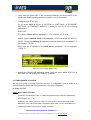
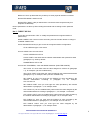
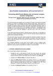
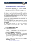
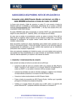
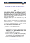
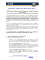
AEQ PHOENIX AUDIOCODECS. APPLICATION NOTE 0-E
AEQ Phoenix Studio units through Internet. Complex scenario
configuration
Through LOCAL network(s), DHCP not used, manual NAT. Using SIP Direct mode
The most convenient and reliable way to connect an IP codec to a remote one through
Internet is by means of a dedicated, exclusive Internet access (DSL, cable modem). In
this application note, a way to achieve the same result will be proposed when this is not
possible as Internet access is shared with other equipments connected within a
managed, LOCAL LAN and DHCP is not available or convenient. This application note
describes the recommended procedure when AEQ SIP Proxy is not reachable or we
don’t want to use it, and SIP signaling is used from end to end, with no servers
involved.
As we need to get access to Internet, a shared resource in this case, it is mandatory to
contact the network administrator in order to have the required resources enabled and
gather all the necessary information.
This document shows the specific steps to make this connection possible in the most
general way possible, although some verification procedures have been omitted in
order to ease the reading, and some particular situations may be easier to solve that
the presented one.
For a detailed explanation of every step, and for details on how to configure other
options that may be more convenient for other cases, the reading of the rest of
application notes, as well as User Manual’s chapter 4, is recommended
1. NETWORK ADMINISTRATION INVOLVEMENT
We will need that the Network Administrator…
1. Provides us with a valid internal IP within the local network, for example
172.26.5.59, for sending SIP signaling as well as audio using RTP protocol.
Both IP will be the same in both cases, and we will refer to it as LOCAL IP.
2. Indicates us the Network Mask, for example 255.255.0.0
3. Tell us the DNS server IP address, for example 172.26.1.1 or a valid external
DNS server for the country we are working at. If it is not provided, we will still be
able to operate provided that we know the IP address of the SIP Proxy
(although it is always recommended to specify it by its DNS name)
4. Provides the Gateway IP address, as an example 172.26.1.1
5. Indicates us the network Public IP address. In most cases, there will be a
single public IP for SIP signaling and RTP traffic. We will refer to it as PUBLIC
IP, for example, 212.170.180.170
APLICACIONES ELECTRONICAS QUASAR S.A.
TEL: (34) 91 686 13 00 - FAX: (34) 91 686 44 92 - E-mail: [email protected] - Web:
1
www.aeq.eu
6. Opens the required ports for audio and signaling. These ports are, by default:
•
SIP signaling PORT (SIP LOCAL PORT): we will obtain it from the
equipment, which will assign port number 5061 by default when in the NAT
TRAVERSAL “MANUAL” mode. It is recommended that port 5062 is also
opened, just in case we want to use both channels of the unit using two
different SIP proxy servers.
•
Ports for audio transmission and control (RTP and RTCP protocols): 5004
and 5005, respectively.
•
STUN ports: 3478 & 3479.
7. Assigns public ports for SIP, RTP and RTCP, for example 8000, 8002 and 8003
respectively, and do a port forwarding that translates the (PUBLIC IP, public
port) pairs to each (LOCAL IP, Phoenix configured port) pair*.
• SIP PUBLIC PORT to SIP LOCAL PORT
(for example, PUBLIC_IP:8000 to LOCAL_IP:5061)
• RTP PUBLIC PORT to RTP LOCAL PORT
(for example, PUBLIC_IP:8002 to LOCAL_IP:5004)
• RTCP PUBLIC PORT to RTCP LOCAL PORT
(for example, PUBLIC_IP:8003 to LOCAL_IP:5005)
*Note that public port numbers can be the same as local ones (5061, 5004, 5005…),
unless the administrator decides the opposite because they are already in use or there
are other IP codecs or SIP equipment in that local area network.
2. CONNECTING AND CONFIGURING THE UNITS
The physical connection will be done to a LAN port.
•
Connect the network cable to the LAN1 port at the back of the AEQ Phoenix
Studio. Connect the other end to the Ethernet port we have been assigned
within the LAN.
•
Connect the analog or digital audio inputs and outputs to the connectors at the
back of the AEQ Phoenix Studio.
•
Connect the IEC mains cable to the back of the AEQ Phoenix Studio.
•
Turn the power switch ON and verify that the front display shows the AEQ logo
after some seconds.
APLICACIONES ELECTRONICAS QUASAR S.A.
TEL: (34) 91 686 13 00 - FAX: (34) 91 686 44 92 - E-mail: [email protected] - Web:
2
www.aeq.eu
•
Verify that the green LED in the connected Ethernet port at the back of the
equipment blinks indicating that there is traffic in the IP connection.
•
Configuring the ETH1 port:
Go to menu MAIN STATUS
SYSTEM
8.SETTINGS
ETHERNET
SETTINGS
ETHERNET MODULE 1, where we will set up the following
parameters:
DHCP OFF
IP: type the LOCAL IP from paragraph 1.1, for example 172.26.5.59
MASK: type the network mask from paragraph 1.2 in, for example 255.255.0.0
GWAY: fill with the Gateway IP address for Internet access from paragraph 1.4,
for example: 172.26.1.1
DNS: type the IP address of the DNS server (paragraph 1.3), for example:
172.26.1.1
Ethernet 1 port configuration screen
•
Select the PROXY SIP operating mode, from the menu MAIN STATUS
SYSTEM
5. INTERFACES
NET 1
MODE
3. OTHER POINTS TO CHECK
We are now going to quickly overview the rest of configuration menus where it is
recommended to check that every parameter is correctly configured.
At MAIN STATUS…
Chn1: Net 1 ONLY G722 OK
(Press the encoder button “SEL” to modify the parameters this channel’s parameters):
INTERFACE: Net 1 ( IP)
CODING( List) : ONLY_G722 for a start, we can test other modes with better quality
afterwards. If the coding lists need to be edited, select option 10 from SYSTEM menu.
AUDIO IN SOURCE: ANALOG for analog XLR inputs.
APLICACIONES ELECTRONICAS QUASAR S.A.
TEL: (34) 91 686 13 00 - FAX: (34) 91 686 44 92 - E-mail: [email protected] - Web:
3
www.aeq.eu
BACK UP: Set it up afterwards only if backup on other physical interface is needed.
RX BUFFER MODE: ADAPTATIVE
RX BUFFER ( MAX): 1000 (in milliseconds. It should be reduced dynamically if no
dropouts are detected)
Rest of parameters: set them up after reading the manual and according to each particular
need.
Net 1 : DIRECT SIP OK.
(Press the encoder button “SEL” to modify the parameters this logical interface’s
parameters):
MODE: DIRECT SIP. If this is not the set mode, press the encoder button to change it
to MODE: DIRECT SIP.
Press ADVANCED soft key to gain access to the logical interface configuration:
Go to USER and type a user name.
Access AUDIO menu and check that:
LOCAL INTERFACE is ETH1
LOCAL PORT is the same that the network administrator has opened for audio
(paragraph 1.6), 5004 by default.
SYMMETRICAL RTP is ON
Access NAT TRAVERSAL, check that MODE: MANUAL (ROUTER CONFIG):
SIP LOCAL IP: must match with the value assigned to LOCAL IP (paragraph
1.1), for example: (can’t be modified here)
SIP LOCAL PORT: must match the value provided by the network administrator
(paragraph 1.6), for example, 5061 (can’t be modified here)
SIP PUBLIC IP: here you must type the PUBLIC_IP value provided by the
network administrator according to paragraph 1.5, for example:
212.170.180.170
SIP PUBLIC PORT: here you must type the value provided by the network
administrator in paragraph 1.7, for example, 8000
RTP LOCAL IP: (can’t be modified here). Must match the value assigned by the
network administrator according to paragraph 1.1, for example: 172.26.5.59
RTP LOCAL PORT: (can’t be modified here). Must match the value provider by
the network administrator according to paragraph 1.6, for example: 5004
RTP PUBLIC IP: here you must type the PUBLIC_IP value provided by the
network administrator in paragraph 1.5, for example: 212.170.180.170
RTP PUBLIC PORT: here you must type the value assigned by the
administrator in paragraph 1.7, for example: 8002
APLICACIONES ELECTRONICAS QUASAR S.A.
TEL: (34) 91 686 13 00 - FAX: (34) 91 686 44 92 - E-mail: [email protected] - Web:
4
www.aeq.eu
4. MAKING A TEST CALL TO PHOENIX MASTER
Finally, we are going to revise the adequate configuration of the equipment, and
prepare it to make a test call to an unit called [email protected] , that AEQ
maintains at the disposal of its customers, continuously transmitting audio and with
reachable in the public IP 212.170.163.189 (at the time of writing this document)
We recommend that a pair of headphones is plugged to the front outlet, or a couple of
monitor speakers are connected to the back side XLR outputs.
It is also advisable that the PHOENIX MASTER and PHOENIX MASTER 2 are added
to the phone book for future tests:
Go to MAIN STATUS
SYSTEM
2. CONTACTS, screen PHONE BOOK.
Press the soft key INSERT.
Following the guidelines in chapter 3.1.2 of the User Manual, fill a name and
URI for Phoenix Master (have in mind that “*” key switches between upper
case, lower case and numbers, and that the space is inserted with key “0”):
NAME: PHOENIX MASTER
TEL: <leave this field blank >
TEL2: <leave this field blank>
URI: [email protected]:5061 (case sensitive)
NAME: PHOENIX MASTER2
TEL: <leave this field blank >
TEL2: <leave this field blank >
URI: [email protected]
Note that PHOENIX MASTER URI has a port number, preceded by the “:”
symbol, after the IP address. In the case of PHOENIX MASTER 2, the port
used for SIP is 5060, the standard one, so we don’t need to add “:5060” at the
end.
Return to MAIN STATUS screen and place the cursor over Chn1.
Press the CALL key associated to the first channel of the audiocodec, which is the
leftmost one of two keys at the front panel of AEQ Phoenix Studio. This will present
the connection configuration menu, CH1 CALL MENU
Press PHONE BOOK, place the cursor over “PHOENIX MASTER” or “PHOENIX
MASTER2” entries that we previously created, and press DIAL soft key to initiate the
call.
APLICACIONES ELECTRONICAS QUASAR S.A.
TEL: (34) 91 686 13 00 - FAX: (34) 91 686 44 92 - E-mail: [email protected] - Web:
5
www.aeq.eu
The OLED screen (sometimes fast) the status call status and the different phases it
steps through: CALLING, CONNECTING, SYNCHRONIZING and finally
CONNECTED.
Verify that the SYNC LED situated under the CALL key is lit in green color, as an
indication that the communication has been correctly established and
synchronized. You should hear audio from Phoenix Master in the headphones.
Established connection detail
Be sure that ON AIR is activated for that communications channel in order to allow
the full-duplex audio transmission from/to the associated XLR connectors.
Once the connection is well established, it can be repeated as many times as
necessary varying the audio coding algorithm until the best possible quality is
reached given the network conditions. (Menu CH1 STATUS
CODING (List).)
The audio coding algorithm lists are created by entering MAIN STATUS
SYSTEM
10. SIP CODEC PROFILES
5. MAKING A CALL TO OTHER PHOENIX CODEC OR TO A N/ACIP COMPLIANT
CODEC
The calls to Phoenix Master or Phoenix Master 2 have been automatically answered.
To make a manual call to other codec, it is necessary to configure the second one the
same way, if it is connected to a managed local network, or in a simpler way if it is
connected to Internet directly through an ADSL router or cable modem with DHCP
server (as explained in the corresponding application notes AN0A or AN0B).
Once the reporter unit can connect properly to Phoenix Master (-2), you can create in
the phone book a contact with the name and URI of the other unit as explained for the
Phoenix Master contact in the previous chapter, and the call can be directly made.
You can also send the call without having previously created a contact in the Phone
Book. Just select the Chn 1 line in the MAIN STATUS screen, press the CALL
corresponding to CH1 (the leftmost one), and you will reach CH1 CALL MENU. Then
select the URI line and edit it in order to type the other equipment’s URI. Now just
validate by pressing the encoder button and press the DIAL soft key.
APLICACIONES ELECTRONICAS QUASAR S.A.
TEL: (34) 91 686 13 00 - FAX: (34) 91 686 44 92 - E-mail: [email protected] - Web:
6
www.aeq.eu
The other equipment CALL LED will blink and the buzzer will sound if it is configured to
do so. When you press the blinking CALL key, the communication should be
established, and the SYNC LED should become green in both ends of the
communication. If you press the ON AIR key the audio from the XLR input will be sent,
and the audio from the opposite unit should be received in the headphones.
In order to set the buzzer, go to MAIN STATUS
select BUZZER = ON
SYSTEM
8 – SETTINGS and
For more information and other configuration options, please read the User Manual and
Application Notes corresponding to other scenarios. If you still have doubts, please
don’t hesitate to contact one of our assistance services:
[email protected]
[email protected]
APLICACIONES ELECTRONICAS QUASAR S.A.
TEL: (34) 91 686 13 00 - FAX: (34) 91 686 44 92 - E-mail: [email protected] - Web:
7
www.aeq.eu