1
FUJITSU Server
PRIMEQUEST 2000 Series
General Description
CA92344-0534-01
Preface
Preface
This manual describes the functions and features of the PRIMEQUEST 2000 series. The manual is intended for system
administrators.
For details on the regulatory compliance statements and safety precautions, see the PRIMEQUEST 2000 Series Safety
and Regulatory Information (CA92344-0523).
Organization of this manual
This manual is organized as follows.
CHAPTER 1 Product Overview
Chapter 1 describes the features, specifications, structural concept, system configuration, hardware technologies, and
software technologies of the PRIMEQUEST 2000 series.
CHAPTER 2 Hardware Configuration
Chapter 2 describes the hardware configurations and system specifications of the PRIMEQUEST 2000 series and the
specifications of individual hardware components.
CHAPTER 3 Software Configuration
Chapter 3 describes the supported operating systems, bundled software, firmware, and operations management software
for the PRIMEQUEST 2000 series.
CHAPTER 4 Functions provided by the PRIMEQUEST 2000 series
Chapter 4 describes the functions and architecture of the system provided by the PRIMEQUEST 2000 series.
CHAPTER 5 Partitioning
Chapter 5 describes the partitioning functions, including PPAR and Flexible I/O, used in the PRIMEQUEST 2000 series.
CHAPTER 6 Redundancy
Chapter 6 describes the redundancy of components for the PRIMEQUEST 2000 series.
CHAPTER 7 Applicable Components for Hot Maintenance
Chapter 7 describes the hot maintenance of hardware components for the PRIMEQUEST 2000 series.
CHAPTER 8 Operations Management Tools
Chapter 8 provides an overview of the operations management tools used in the PRIMEQUEST 2000 series.
CHAPTER 9 Server Maintenance
Chapter 9 describes the considerations to take into account in system design for server maintenance.
CHAPTER 10 Hardware Installation and Connection
Chapter 10 provides a link to the PRIMEQUEST 2000 Series Hardware Installation Manual.
Appendix A Component Mounting Locations
Appendix A provides a link to Appendix B Physical Mounting Locations and Port Numbers in the PRIMEQUEST 2000
Series Administration Manual.
Appendix B Mounting Locations, BUS numbers, and Slot numbers
Appendix B provides a link to Appendix D Physical Locations and BUS Numbers of Built-in I/O, and PCI Slot Mounting
Locations and Slot Numbers in the PRIMEQUEST 2000 Series Administration Manual.
Appendix C Status checks with LEDs
Appendix C provides a link to Appendix F Status Checks with LEDs in the PRIMEQUEST 2000 Series Administration
Manual.
Appendix D Component Mounting Conditions
i
CA92344-0534-01
Preface
Appendix D provides a link to Appendix G Component Mounting Conditions in the PRIMEQUEST 2000 Series
Administration Manual.
Appendix E Cable (Specifications
Appendix E provides a link to Chapter 2 Connection Information in the PRIMEQUEST 2000 Series Hardware Installation
Manual.
Appendix F Tree Structure of the MIB provided with the PRIMEQUEST 2000 series
Appendix F provides a link to Appendix H Tree Structure of the MIB Provided with the PRIMEQUEST 2000 Series in the
PRIMEQUEST 2000 Series Administration Manual.
Appendix G Linkage functions and Services
Appendix G describes the linkage functions and services provided by the PRIMEQUEST 2000 series.
ii
CA92344-0534-01
Preface
Revision History
Edition
01
Date
2014-08-12
Revised location (type) (*1)
Description
- The edition is initialized to "01"
All pages
for changing manual code
*1: Chapter, section, and item numbers in the "Revised location" column refer to those in the latest edition of the
document. However, a number marked with an asterisk (*) denotes a chapter, section, or item in a previous
edition of the document.
iii
CA92344-0534-01
Preface
Product operating environment
This product is a computer intended for use in a computer room environment. For details on the product operating
environment, see the following manual:
PRIMEQUEST 2000 Series Hardware Installation Manual (CA92344-0535)
Safety Precautions
Alert messages
This manual uses the following alert messages to prevent users and bystanders from being injured and to prevent
property damage.
This indicates a hazardous (potentially dangerous) situation that is likely to result in death or serious
personal injury if the user does not perform the procedure correctly.
This indicates a hazardous situation that could result in minor or moderate personal injury if the user
does not perform the procedure correctly. This also indicates that damage to the product or other
property may occur if the user does not perform the procedure correctly.
This indicates information that could help the user use the product more efficiently.
Alert messages in the text
An alert statement follows an alert symbol. An alert statement is indented on both ends to distinguish it from regular text.
Similarly, one space line is inserted before and after the alert statement.
Only Fujitsu certified service engineers should perform the following tasks on this product and the
options provided by Fujitsu. Customers must not perform these tasks under any circumstances.
Otherwise, electric shock, injury, or fire may result.
-
Newly installing or moving equipment
-
Removing the front, rear, and side covers
-
Installing and removing built-in options
-
Connecting and disconnecting external interface cables
-
Maintenance (repair and periodic diagnosis and maintenance)
The List of important alert items table lists important alert items.
List of important alert items
This manual does not contain important alert items.
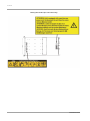
Warning labels
Never remove the warning labels.
iv
CA92344-0534-01
Preface
Warning label location (the main cabinet top)
v
CA92344-0534-01
Preface
Warning label location (the main cabinet left)
Warning label location (PCI_Box)
vi
CA92344-0534-01
Preface
Notes on Handling the Product
About this product
This product is designed and manufactured for standard applications. Such applications include, but are not limited to,
general office work, personal and home use, and general industrial use. The product is not intended for applications that
require extremely high levels of safety to be guaranteed (referred to below as "safety-critical" applications). Use of the
product for a safety-critical application may present a significant risk of personal injury and/or death. Such applications
include, but are not limited to, nuclear reactor control, aircraft flight control, air traffic control, mass transit control, medical
life support, and missile launch control. Customers shall not use the product for a safety-critical application without
guaranteeing the required level of safety. Customers who plan to use the product in a safety-critical system are requested
to consult the Fujitsu sales representatives in charge.
Storage of accessories
Keep the accessories in a safe place because they are required for server operation.
Adding optional products
For stable operation of the PRIMEQUEST 2000 series server, use only a Fujitsu-certified optional product as an added
option.
Note that the PRIMEQUEST 2000 series server is not guaranteed to operate with any optional product not certified by
Fujitsu.
Exportation/release of this product
Exportation/release of this product may require necessary procedures in accordance with the regulations of the Foreign
Exchange and Foreign Trade Control Law of Japan and/or US export control laws.
Maintenance
Only Fujitsu certified service engineers should perform the following tasks on this product and the
options provided by Fujitsu. Customers must not perform these tasks under any circumstances.
Otherwise, electric shock, injury, or fire may result.
-
Newly installing or moving equipment
-
Removing the front, rear, and side covers
-
Installing and removing built-in options
-
Connecting and disconnecting external interface cables
-
Maintenance (repair and periodic diagnosis and maintenance)
Only Fujitsu certified service engineers should perform the following tasks on this product and the
options provided by Fujitsu. Customers must not perform these tasks under any circumstances.
Otherwise, product failure may result. PRIMEQUEST 2000 Series General Description
-
Unpacking an optional Fujitsu product, such as an optional adapter, delivered to the customer
Modifying or recycling the product
Modifying this product or recycling a secondhand product by overhauling it without prior approval
may result in personal injury to users and/or bystanders or damage to the product and/or other
property.
Note on erasing data from hard disks when disposing of the product or transferring it
vii
CA92344-0534-01
Preface
Disposing of this product or transferring it as is may enable third parties to access the data on the hard disk and use it for
unforeseen purposes. To prevent the leakage of confidential information and important data, all of the data on the hard
disk must be erased before disposal or transfer of the product.
However, it can be difficult to completely erase all of the data from the hard disk. Simply initializing (reformatting) the hard
disk or deleting files on the operating system is insufficient to erase the data, even though the data appears at a glance to
have been erased. This type of operation only makes it impossible to access the data from the operating system.
Malicious third parties can restore this data.
If you save your confidential information or other important data on the hard disk, you should completely erase the data,
instead of simply carrying out the aforementioned operation, to prevent the data from being restored. To prevent important
data on the hard disk from being leaked when the product is disposed of or transferred, you will need to take care to erase
all the data recorded on the hard disk on your own responsibility.
Furthermore, if a software license agreement restricts the transfer of the software (operating system and application
software) on the hard disk in the server or other product to a third party, transferring the product without deleting the
software from the hard disk may violate the agreement. Adequate verification from this point of view is also necessary.
Support and service
Product and service inquiries
For all product use and technical inquiries, contact the distributor where you purchased your product, or a Fujitsu sales
representative or systems engineer (SE). If you do not know the appropriate contact address for inquiries about the
PRIMEQUEST 2000 series, use the Fujitsu contact line.
Fujitsu contact line
We accept Web inquiries. For details, visit our website:
https://www-s.fujitsu.com/global/contact/computing/PRMQST_feedback.html
Warranty
If a component failure occurs during the warranty period, we will repair it free of charge in accordance with the terms of the
warranty agreement. For details, see the warranty.
Before requesting a repair
If a problem occurs with the product, confirm the problem by referring to 11.2 Troubleshooting in the PRIMEQUEST 2000
Series Administration Manual (CA92344-0537). If the error recurs, contact your sales representative or a field engineer.
Confirm the model name and serial number shown on the label affixed to the right front of the device and report it. Also
check any other required items beforehand according to 11.2 Troubleshooting in the PRIMEQUEST 2000 Series
Administration Manual (CA92344-0537).
The system settings saved by the customer will be used during maintenance.
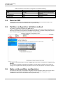
Manual
How to use this manual
This manual contains important information about the safe use of this product. Read the manual thoroughly to understand
the information in it before using this product. Be sure to keep this manual in a safe and convenient location for quick
reference.
Fujitsu makes every effort to prevent users and bystanders from being injured and to prevent property damage. Be sure to
use the product according to the instructions in this manual.
viii
CA92344-0534-01
Preface
Exportation/release of this document may require necessary procedures in accordance with the regulations of the Foreign
Exchange and Foreign Trade Control Law of Japan and/or US export control laws.
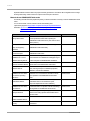
Manuals for the PRIMEQUEST 2000 series
The following manuals have been prepared to provide you with the information necessary to use the PRIMEQUEST 2000
series.
You can access HTML versions of these manuals at the following sites:
Japanese-language site: http://jp.fujitsu.com/platform/server/primequest/manual/2000/
Global site: http://www.fujitsu.com/global/services/computing/server/primequest/
http://manuals.ts.fujitsu.com/
Title
Description
PRIMEQUEST 2000 Series
Describes what manuals you should read and how to
Getting Started Guide
access important information after unpacking the
Manual code
CA92344-0522
PRIMEQUEST 2000 series server. (This manual comes
with the product.)
PRIMEQUEST 2000 Series
Contains important information required for using the
Safety and Regulatory
PRIMEQUEST 2000 series safely.
CA92344-0523
Information
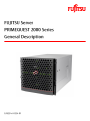
PRIMEQUEST 2000 Series
Describes the functions and features of the
General Description
PRIMEQUEST 2000 series.
SPARC Enterprise/
Provides the necessary information and concepts you
PRIMEQUEST Common
should understand for installation and facility planning for
Installation Planning Manual
SPARC Enterprise and PRIMEQUEST installations.
PRIMEQUEST 2000 Series
Includes the specifications of and the installation location
CA92344-0534
C120-H007EN
CA92344-0535
Hardware Installation Manual requirements for the PRIMEQUEST 2000 series.
PRIMEQUEST 2000 Series
Describes how to set up the PRIMEQUEST 2000 series
Installation Manual
server, including the steps for installation preparation,
CA92344-0536
initialization, and software installation.
PRIMEQUEST 2000 Series
Describes how to use the Web-UI and UEFI to assure
User Interface Operating
proper operation of the PRIMEQUEST 2000 series
Instructions
server.
PRIMEQUEST 2000 Series
Describes how to use tools and software for system
Administration Manual
administration and how to maintain the system
CA92344-0538
CA92344-0537
(component replacement and error notification).
PRIMEQUEST 2000 Series
Provides information on operation methods and settings,
Tool Reference
including details on the MMB and UEFI functions.
PRIMEQUEST 2000 Series
Lists the messages that may be displayed when a
Message Reference
problem occurs during operation and describes how to
CA92344-0539
CA92344-0540
respond to them.
PRIMEQUEST 2000 Series
Describes REMCS service installation and operation
CA92344-0542
REMCS Installation Manual
PRIMEQUEST 2000 Series
Defines the PRIMEQUEST 2000 series related terms and CA92344-0541
Glossary
abbreviations.
ix
CA92344-0534-01
Preface
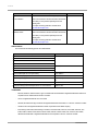
Related manuals
The following manuals relate to the PRIMEQUEST 2000 series.
You can access these manuals at the following site:
http://manuals.ts.fujitsu.com/
Contact your sales representative for inquiries about the ServerView manuals.
Title
Description
Manual code
ServerView Suite ServerView Describes how to install and start ServerView Operations None
Operations Manager Quick
Manager in a Windows environment.
Installation (Windows)
ServerView Suite ServerView Describes how to install and start ServerView Operations None
Operations Manager Quick
Manager in a Linux environment.
Installation (Linux)
ServerView Suite ServerView Describes the installation procedure using ServerView
Installation Manager
ServerView Suite ServerView Provides an overview of server monitoring using
Operations Manager Server
ServerView Operations Manager, and describes the user
Management
interface of ServerView Operations Manager.
ServerView Suite ServerView Describes RAID management using ServerView RAID
RAID Management User
None
Installation Manager.
None
None
Manager.
Manual
ServerView Suite Basic
Describes basic concepts about ServerView Suite.
None
ServerView Operations
Describes installation and update installation of
None
Manager Installation
ServerView Linux Agent.
Concepts
ServerView Agents for Linux
ServerView Operations
Describes installation and update installation of
Manager Installation
ServerView Windows Agent.
None
ServerView Agents for
Windows
ServerView Mission Critical
Describes the necessary functions unique to
Option User Manual
PRIMEQUEST (cluster linkage) and ServerView Mission
None
Critical Option (SVmco), which is required for supporting
these functions.
ServerView RAID Manager
Describes the installation and settings required to use
VMware vSphere ESXi 5
ServerView RAID Manager on the VMware vSphere
Installation Guide
ESXi 5 server.
MegaRAID SAS Software
Provides technical information on using array controllers.
None
None
Refer to the manual from the second DVD for ServerView
Suite which you can purchase optionally or from the
following URL:
The Fujitsu Technology Solutions manuals server
http://manuals.ts.fujitsu.com/
x
CA92344-0534-01
Preface
Title
Description
Manual code
MegaRAID SAS Device
Provides technical information on using array controllers.
Driver Installation
Refer to the manual from the second DVD for ServerView
None
Suite which you can purchase optionally or from the
following URL:
The Fujitsu Technology Solutions manuals server
http://manuals.ts.fujitsu.com/
Modular RAID Controller
Provides technical information on using array controllers.
Installation Guide
Refer to the manual from the second DVD for ServerView
None
Suite which you can purchase optionally or from the
following URL:
The Fujitsu Technology Solutions manuals server
http://manuals.ts.fujitsu.com/
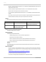
Abbreviations
This manual uses the following product name abbreviations.
Formal product name
Abbreviation
Microsoft ® Windows Server ® 2012 R2 Datacenter
Windows, Windows Server 2012
Microsoft ® Windows Server ® 2012 R2 Standard
Microsoft ® Windows Server ® 2012 Datacenter
Microsoft ® Windows Server ® 2012 Standard
Microsoft ® Windows Server ® 2008 R2 Standard
Windows, Windows Server 2008 R2
Microsoft ® Windows Server ® 2008 R2 Enterprise
Microsoft ® Windows Server ® 2008 R2 Datacenter
Red Hat ® Enterprise Linux ® 6 (for Intel64)
Linux, RHEL6
Oracle Linux 6 (x86_64)
Oracle Linux, Oracle Linux 6
VMware vSphere (R) 5
VMware, vSphere 5.x, VMware 5, VMware
5.x
VMware (R) ESXi (TM) 5
ESXi, ESXi 5, ESXi 5.x
Novell (R) SUSE(R) LINUX Enterprise Server 11 Service Pack 3
SLES11 SP3
Trademarks
-
Microsoft, Windows, Windows Server, Hyper-V and BitLocker are trademarks or registered trademarks of Microsoft
Corporation in the United States and/or other countries.
-
Linux is a registered trademark of Linus Torvalds.
-
Red Hat, the Shadowman logo and JBoss are registered trademarks of Red Hat, Inc. in the U.S. and other countries.
-
Oracle and Java are registered trademark of Oracle Corporation and its related company.
-
Intel, Intel logo, Intel Inside, Intel Inside logo, Intel Atom, Intel Atom Inside ,Intel Core, Core Inside, Intel vPro, vPro
Inside, Celeron, Celeron Inside, Itanium, Itanium Inside, Pentium, Pentium Inside, Xeon, Xeon Phi, Xeon Inside,
Ultrabook are trademarks or registered trademarks of Intel Corporation in the U.S. and other countries.
xi
CA92344-0534-01
Preface
-
Ethernet is a registered trademark of Fuji Xerox Co., Ltd. in Japan and is a registered trademark of Xerox Corp. in the
United States and other countries.
-
VMware is a trademark or registered trademark of VMware, Inc. in the United States and other countries.
-
Novell and SUSE Linux Enterprise Server are trademarks of Novell, Inc.
-
Xen is a trademark or registered trademark of Citrix Systems, Inc. or its subsidiaries in the United States and other
countries.
-
Other company names and product names are the trademarks or registered trademarks of their respective owners.
-
Trademark indications are omitted for some system and product names in this manual.
Notation
This manual uses the following fonts and symbols to express specific types of information.
Font or symbols
italics
Meaning
Example
Title of a manual that you should refer to
See the PRIMEQUEST 2000 Series
Installation Manual (CA92344-0536).
[]
Window names as well as the names of
Click the [OK] button.
buttons, tabs, and drop-down menus in
windows are enclosed in brackets.
Notation for the CLI (command line interface)
The following notation is used for commands.
Command syntax
Command syntax is represented as follows.
-
Variables requiring the entry of a value are enclosed in angle brackets < >.
-
Optional elements are enclosed in brackets [ ].
-
Options for optional keywords are grouped in | (stroke) separated lists enclosed in brackets [ ].
-
Options for required keywords are grouped in | (stroke) separated lists enclosed in braces { }.
Command syntax is written in a box.
Remarks
The command output shown in the PDF manuals may include line feeds at places where there is no line feed symbol
(\ at the end of the line).
Notes on notations
-
If you have a comment or request regarding this manual, or if you find any part of this manual unclear, please take a
moment to share it with us by filling in the form at the following webpage, stating your points specifically, and sending
the form to us:
https://www-s.fujitsu.com/global/contact/computing/PRMQST_feedback.html
-
The contents of this manual may be revised without prior notice.
-
In this manual, the Management Board and MMB firmware are abbreviated as "MMB."
xii
CA92344-0534-01
Preface
-
In this manual, IOU_10GbE and IOU_1GbE are collectively referred to as IO Units.
-
Screenshots contained in this manual may differ from the actual product screen displays.
-
The IP addresses, configuration information, and other such information contained in this manual are display
examples and differ from that for actual operation.
-
The PDF file of this manual is intended for display using Adobe® Reader® in single page viewing mode at 100%
zoom.
This manual shall not be reproduced or copied without the permission of Fujitsu Limited.
Copyright 2014 FUJITSU LIMITED
xiii
CA92344-0534-01
Preface
Contents
Preface................................................................................................................................................................................................................ i
CHAPTER 1
1.1
1.1.1
Product Overview.................................................................................................................................................................1
Introduction of the PRIMEQUEST 2000 series............................................................................................................................1
Features ....................................................................................................................................................................................1
1.2
Product Lineup...............................................................................................................................................................................2
1.3
PRIMEQUEST 2000 series configuration....................................................................................................................................4
1.3.1
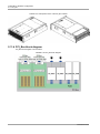
Hardware configuration ............................................................................................................................................................5
1.3.2
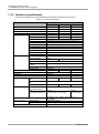
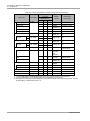
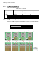
Hardware specifications ........................................................................................................................................................ 10
1.3.3
Partition management ........................................................................................................................................................... 11
1.3.4
1.4
Hardware management ........................................................................................................................................................ 11
Hardware technologies............................................................................................................................................................... 12
1.4.1
CPU ........................................................................................................................................................................................ 13
1.4.2
QuickPath Interconnect (QPI) ............................................................................................................................................... 13
1.4.3
Hyper Threading Technology Function ................................................................................................................................ 13
1.4.4
Memory Mirror Functions ...................................................................................................................................................... 14
1.4.5
Memory Sparing Function ..................................................................................................................................................... 14
1.4.6
Reserved SB Function .......................................................................................................................................................... 14
1.4.7
Hardware RAID...................................................................................................................................................................... 14
1.4.8
PCI Hot Plug Function ........................................................................................................................................................... 15
1.4.9
Security and Encryption Function ......................................................................................................................................... 15
1.4.10
Trusted Platform Module (TPM)....................................................................................................................................... 15
1.4.11
Physical Partitioning (PPAR) ............................................................................................................................................ 15
1.4.12
Extended Partitioning ........................................................................................................................................................ 16
1.4.13
Dynamic Reconfiguration (DR) function .......................................................................................................................... 16
1.4.14
Flexible I/O......................................................................................................................................................................... 16
1.4.15
Virtual Support Virtualization Technology (VT) Function ................................................................................................ 16
1.4.16
Management Board (MMB) ............................................................................................................................................. 17
1.4.17
Network (LAN)................................................................................................................................................................... 17
1.4.18
Preboot eXecution Environment (PXE) ........................................................................................................................... 18
1.4.19
iSCSI boot and iSCSI connection .................................................................................................................................... 19
1.4.20
FCoE boot and FCoE connection .................................................................................................................................... 20
1.4.21
Wake on LAN (WOL)........................................................................................................................................................ 21
1.4.22
sadump.............................................................................................................................................................................. 21
1.4.23
Green Support and Power Saving Technology .............................................................................................................. 21
1.4.24
Active Processor Cores Function..................................................................................................................................... 21
1.4.25
Optimal Fan Control Cooling (Optimization of rotation per minute of fans).................................................................... 22
1.4.26
Air Flow Monitoring ........................................................................................................................................................... 22
1.4.27
Optimal Power Allocation (Optimization of the number of operation power sources) ................................................... 22
1.4.28
Power Consumption Monitoring....................................................................................................................................... 22
1.4.29
Power Saving .................................................................................................................................................................... 23
1.4.30
Agentless Monitoring ........................................................................................................................................................ 23
1.5
Software technologies ................................................................................................................................................................ 23
xiv
CA92344-0534-01
Preface
1.5.1
Firmware ................................................................................................................................................................................ 23
1.5.2
Operating system and virtualization software....................................................................................................................... 24
1.5.3
Server management software............................................................................................................................................... 24
1.5.4
Fujitsu middleware products.................................................................................................................................................. 27
1.5.5
Clustering ............................................................................................................................................................................... 27
CHAPTER 2
Hardware Configuration.................................................................................................................................................... 28
2.1
Components ............................................................................................................................................................................... 28
2.2
Base cabinet ............................................................................................................................................................................... 30
2.3
CPU ............................................................................................................................................................................................. 33
2.3.1
2.4
Support CPU list..................................................................................................................................................................... 33
DIMM (Memory module) ............................................................................................................................................................ 33
2.4.1
Supported DIMM ................................................................................................................................................................... 34
2.4.2
DIMM slot locations................................................................................................................................................................ 34
2.4.3
DIMM installation group ......................................................................................................................................................... 34
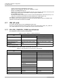
2.5
SB (System board) ..................................................................................................................................................................... 34
2.5.1
SB specifications.................................................................................................................................................................... 34
2.5.2
USB ........................................................................................................................................................................................ 36
2.5.3
VGA ........................................................................................................................................................................................ 37
2.6
MMB (Management Board) ....................................................................................................................................................... 37
2.6.1
MMB specifications ................................................................................................................................................................ 37
2.6.2
MMB serial interface .............................................................................................................................................................. 38
2.6.3
MMB LAN interface ............................................................................................................................................................... 38
2.7
IOU (IO unit) ................................................................................................................................................................................ 39
2.7.1
IOU (IOU_1GbE/IOU_10GbE) specifications ...................................................................................................................... 39
2.7.2
IOU card slot .......................................................................................................................................................................... 41
2.8
2.8.1
2.9
DU (Disk unit) .............................................................................................................................................................................. 41
DU specifications ................................................................................................................................................................... 42
Internal storage device ............................................................................................................................................................... 44
2.9.1
Internal HDD (Hard disk drive) .............................................................................................................................................. 44
2.9.2
Internal SSD ........................................................................................................................................................................... 45
2.10
2.10.1
2.11
OPL (Operator panel) ................................................................................................................................................................. 45
OPL specifications ............................................................................................................................................................ 47
PCI_Box ...................................................................................................................................................................................... 47
2.11.1
PCI_Box specification ....................................................................................................................................................... 47
2.11.2
PCI_Box interface ............................................................................................................................................................. 47
2.11.3
PCI_Box external view...................................................................................................................................................... 49
2.11.4
PCI_Box block diagram .................................................................................................................................................... 50
2.11.5
PCI_Box component list ................................................................................................................................................... 51
2.11.6
PCI_Box connection pattern............................................................................................................................................. 51
2.11.7
PCI _Box connection conditions ...................................................................................................................................... 53
2.11.8
PCI_Box number .............................................................................................................................................................. 55
2.12
PCI Express slot ......................................................................................................................................................................... 55
2.12.1
PCI Express slot (IOU) specifications .............................................................................................................................. 55
2.12.2
PCI Express slot (PCI_Box) specifications ...................................................................................................................... 56
2.12.3
PCI Express cassette ....................................................................................................................................................... 56
xv
CA92344-0534-01
Preface
2.13
Middle Plane (MP) ...................................................................................................................................................................... 56
2.14
Power Supply Unit (PSU)........................................................................................................................................................... 56
2.14.1
PSU_P specifications ....................................................................................................................................................... 57
2.14.2
PSU_S specifications ....................................................................................................................................................... 58
2.14.3
Number of PSUs required ................................................................................................................................................ 58
2.14.4
Dual power feed configuration.......................................................................................................................................... 58
2.14.5
AC cable specifications..................................................................................................................................................... 58
2.14.6
2.15
Mounting conditions when using 100V power supply..................................................................................................... 58
Fan (Cooling mechanism) .......................................................................................................................................................... 58
CHAPTER 3
Software Configuration ..................................................................................................................................................... 60
3.1
Bundled electronic media ........................................................................................................................................................... 60
3.2
OS................................................................................................................................................................................................ 60
3.3
Bundled software ........................................................................................................................................................................ 60
3.4
Supplied Drivers.......................................................................................................................................................................... 61
3.5
Firmware ..................................................................................................................................................................................... 61
3.6
Operations Management Software............................................................................................................................................ 61
CHAPTER 4
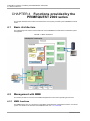
Functions provided by the PRIMEQUEST 2000 series.................................................................................................. 62
4.1
Basic Architecture ....................................................................................................................................................................... 62
4.2
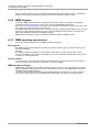
Management with MMB ............................................................................................................................................................. 62
4.2.1
MMB functions ....................................................................................................................................................................... 62
4.2.2
MMB firmware........................................................................................................................................................................ 63
4.2.3
MMB operating environment................................................................................................................................................. 63
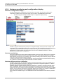
4.2.4
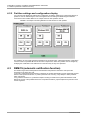
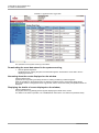
Hardware monitoring and configuration display ................................................................................................................... 64
4.2.5
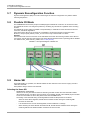
Partition settings and configuration display........................................................................................................................... 65
4.3
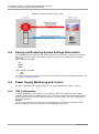
REMCS (automatic notification function)................................................................................................................................... 65
4.4
Saving and Restoring System Settings Information ................................................................................................................. 66
4.5
Power Supply Monitoring and Control ....................................................................................................................................... 66
4.5.1
PSU Configuration ................................................................................................................................................................. 66
4.5.2
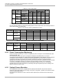
Power Consumption Monitoring............................................................................................................................................ 67
4.5.3
Optimal Power Allocation ...................................................................................................................................................... 67
4.5.4
Scheduled Operations ........................................................................................................................................................... 68
4.5.5
Remote Power Supply Operations ....................................................................................................................................... 68
4.5.6
UPS ........................................................................................................................................................................................ 68
4.6
Clock feature ............................................................................................................................................................................... 68
4.6.1
MMB, BIOS and BMC Time Management .......................................................................................................................... 68
4.6.2
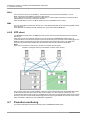
NTP client ............................................................................................................................................................................... 69
4.7
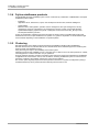
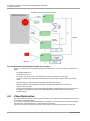
Proactive monitoring ................................................................................................................................................................... 69
4.8
Video Redirection........................................................................................................................................................................ 71
4.9
Console redirection ..................................................................................................................................................................... 72
4.10
Virtual media ............................................................................................................................................................................... 72
4.11
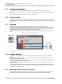
sadump ....................................................................................................................................................................................... 72
4.11.1
sadump firmware .............................................................................................................................................................. 72
4.12
Memory Dump Function (Linux) ................................................................................................................................................ 72
4.13
Memory Dump Function (Windows).......................................................................................................................................... 73
CHAPTER 5
Partitioning ......................................................................................................................................................................... 74
xvi
CA92344-0534-01
Preface
5.1
Partitioning Function ................................................................................................................................................................... 74
5.2
Physical Partitioning (PPAR)...................................................................................................................................................... 74
5.2.1
Partition granularity ................................................................................................................................................................ 75
5.2.2
5.3
Partition Configuration rule .................................................................................................................................................... 76
Extended Partitioning.................................................................................................................................................................. 76
5.3.1
Partition granularity of the Extended Partitioning.................................................................................................................. 76
5.3.2
Use conditions of the Extended Partitioning ......................................................................................................................... 76
5.3.3
Configuration rules of the Extended Partitioning .................................................................................................................. 76
5.4
Reserved SB............................................................................................................................................................................... 77
5.5
Partition configuration definition method .................................................................................................................................... 77
5.6
Notes on the partition configuration............................................................................................................................................ 77
5.7
Dynamic Reconfiguration Function............................................................................................................................................ 78
5.8
Flexible I/O Mode........................................................................................................................................................................ 78
5.9
Home SB..................................................................................................................................................................................... 78
CHAPTER 6
Redundancy ...................................................................................................................................................................... 80
6.1
Redundancy................................................................................................................................................................................ 80
6.2
Redundancy of components ...................................................................................................................................................... 80
6.3
Redundancy of HDD .................................................................................................................................................................. 80
6.3.1
Redundancy of the disk ......................................................................................................................................................... 80
6.4
Redundancy of the Management LAN...................................................................................................................................... 82
6.5
Operation LAN Redundancy...................................................................................................................................................... 82
6.6
Degradation Function ................................................................................................................................................................. 82
CHAPTER 7
Applicable Components for Hot Maintenance................................................................................................................. 83
7.1
Overview of Hot Maintenance.................................................................................................................................................... 83
7.2
List of Components..................................................................................................................................................................... 83
CHAPTER 8
Operations Management Tools ....................................................................................................................................... 84
8.1
Overview of Operations Management Tools ............................................................................................................................ 84
8.2
MMB ............................................................................................................................................................................................ 84
8.2.1
Graphical User Interface (GUI).............................................................................................................................................. 84
8.2.2
Command line interface (CLI) ............................................................................................................................................... 85
8.3
Video redirection ......................................................................................................................................................................... 85
8.4
Console Redirection ................................................................................................................................................................... 85
8.5
Virtual Media ............................................................................................................................................................................... 85
8.6
ServerView Suite (SVS) ............................................................................................................................................................. 85
8.7
UEFI ............................................................................................................................................................................................ 87
CHAPTER 9
Server Maintenance.......................................................................................................................................................... 88
9.1
Maintenance Policy / Preventive Maintenance ......................................................................................................................... 88
9.2
Notes on Maintenance ............................................................................................................................................................... 88
9.2.1
Firmware Setting Information ................................................................................................................................................ 88
9.2.2
Logs collected by the MMB ................................................................................................................................................... 88
CHAPTER 10
Hardware Installation and Connection ........................................................................................................................ 90
Appendix A Component Mounting Locations ............................................................................................................................................... 91
Appendix B Mounting Locations, BUS numbers, and Slot numbers .......................................................................................................... 92
Appendix C Status checks with LEDs........................................................................................................................................................... 93
Appendix D Component Mounting Conditions ............................................................................................................................................. 94
xvii
CA92344-0534-01
Preface
Appendix E Cable (Specifications ................................................................................................................................................................. 95
Appendix F Tree Structure of the MIB provided with the PRIMEQUEST 2000 series .............................................................................. 96
Appendix G Linkage functions and Services ................................................................................................................................................ 97
G.1
Linkage with Systemwalker Centric Manager........................................................................................................................... 97
G.2
Remote Customer Support System (REMCS) ......................................................................................................................... 97
Appendix H Function list supported by OS ................................................................................................................................................... 98
xviii
CA92344-0534-01
Preface
Figures
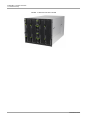
FIGURE 1.1 External Overview of 2400E and 2800E ............................................................................................................................2
FIGURE 1.2 External Overview of 2800B ...............................................................................................................................................3
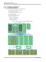
FIGURE 1.3 Configuration conceptual diagram......................................................................................................................................4
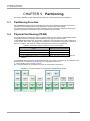
FIGURE 1.4 Hardware configuration image (PRIMEQUEST 2400E)...................................................................................................5
FIGURE 1.5 Hardware configuration image (PRIMEQUEST 2800E)...................................................................................................7
FIGURE 1.6 Hardware configuration image (PRIMEQUEST 2800B)...................................................................................................9
FIGURE 1.7 Configuration diagram of the PRIMEQUEST 2000 series operation management ..................................................... 25
FIGURE 1.8 SVIM setup flow................................................................................................................................................................ 26
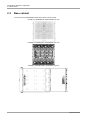
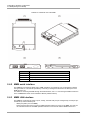
FIGURE 2.1 PRIMEQUEST 2400E/2800E front view ........................................................................................................................ 30
FIGURE 2.2 PRIMEQUEST 2400E/2800E rear view ......................................................................................................................... 30
FIGURE 2.3 PRIMEQUEST 2400E/2800E top view........................................................................................................................... 30
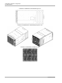
FIGURE 2.4 PRIMEQUEST 2400E/2800E right view......................................................................................................................... 31
FIGURE 2.5 PRIMEQUEST 2400E/2800E perspective view............................................................................................................. 31
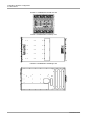
FIGURE 2.6 PRIMEQUEST 2800B front view .................................................................................................................................... 31
FIGURE 2.7 PRIMEQUEST 2800B rear view ..................................................................................................................................... 32
FIGURE 2.8 PRIMEQUEST 2800B top view....................................................................................................................................... 32
FIGURE 2.9 PRIMEQUEST 2800B right view..................................................................................................................................... 32
FIGURE 2.10 PRIMEQUEST 2800B perspective view ...................................................................................................................... 33
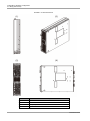
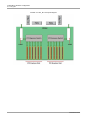
FIGURE 2.11 SB External view ............................................................................................................................................................ 35
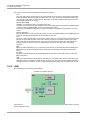
FIGURE 2.12 system diagram .............................................................................................................................................................. 36
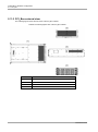
FIGURE 2.13 External view of the MMB .............................................................................................................................................. 38
FIGURE 2.14 External view of IOU_1GbE........................................................................................................................................... 40
FIGURE 2.15 External view of IOU_10GbE......................................................................................................................................... 41
FIGURE 2.16 DU conceptual diagram ................................................................................................................................................. 42
FIGURE 2.17 External view of the DU.................................................................................................................................................. 43
FIGURE 2.18 External view of OPL...................................................................................................................................................... 46
FIGURE 2.19 PCI_Box conceptual diagram ........................................................................................................................................ 48
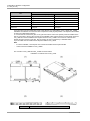
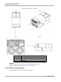
FIGURE 2.20 Orthographic view of the PCI_Box cabinet ................................................................................................................... 49
FIGURE 2.21 Perspective views of the PCI_Box cabinet ................................................................................................................... 50
FIGURE 2.22 PCI_Box block diagram ................................................................................................................................................. 50
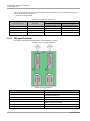
FIGURE 2.23 PCI_Box connection diagram (maximum configuration) for mounted four IOU_1GbEs ........................................... 51
FIGURE 2.24 PCI_Box connection diagram (maximum configuration) for mounted four IOU_10GbEs ......................................... 52
FIGURE 2.25 Straight connection (permitted)...................................................................................................................................... 53
FIGURE 2.26 Crossover connection (permitted) ................................................................................................................................. 53
FIGURE 2.27 Connection to different PCI_Boxes pattern 1 (permitted)............................................................................................. 54
FIGURE 2.28 Connection to different PCI_Boxes pattern 2 (permitted)............................................................................................. 54
FIGURE 2.29 Connection from IOU_1GbE and IOU_10GbE (permitted) ......................................................................................... 54
FIGURE 2.30 PCI_Box shared by different PRIMEQUEST cabinet (not permitted) ......................................................................... 55
FIGURE 2.31 External view of the PSU ............................................................................................................................................... 57
FIGURE 4.1 Basic architecture ............................................................................................................................................................. 62
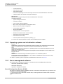
FIGURE 4.2 [System Status] screen (Example of configuration display screen) ............................................................................... 64
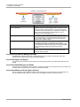
FIGURE 4.3 Example of mounting different OS and versions on each partition................................................................................ 65
xix
CA92344-0534-01
Preface
FIGURE 4.4 REMCS (Automatic report function) ................................................................................................................................ 66
FIGURE 4.5 Diagram of time synchronization (of three 3 NTP servers) ............................................................................................ 69
FIGURE 4.6 Flow of Proactive monitoring............................................................................................................................................ 71
FIGURE 4.7 Sadump conceptual diagram........................................................................................................................................... 72
FIGURE 5.1 Conceptual diagram of the partitioning (PRIMEQUEST 2400E) ................................................................................... 74
FIGURE 5.2 Conceptual diagram of the partitioning (PRIMEQUEST 2800E) ................................................................................... 75
FIGURE 5.3 [Partition Configuration] screen ........................................................................................................................................ 77
FIGURE 5.4 Conceptual diagram of Flexible I/O ................................................................................................................................. 78
FIGURE 8.1 Overall configuration diagram of the operations management tools ............................................................................. 84
FIGURE 9.1 [System Event Log] Screen ............................................................................................................................................. 89
xx
CA92344-0534-01
Preface
Tables
TABLE 1.1 Hardware specifications...................................................................................................................................................... 10
TABLE 1.2 Hardware RAID Level......................................................................................................................................................... 15
TABLE 1.3 VT ........................................................................................................................................................................................ 16
TABLE 1.4 PXE boot support (external) ............................................................................................................................................... 18
TABLE 1.5 iSCSI boot ........................................................................................................................................................................... 19
TABLE 1.6 iSCSI connections............................................................................................................................................................... 19
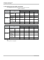
TABLE 1.7 FCoE boot ........................................................................................................................................................................... 20
TABLE 1.8 FCoE connections .............................................................................................................................................................. 20
TABLE 1.9 WOL Support ...................................................................................................................................................................... 21
TABLE 1.10 Active Processor Cores specifications............................................................................................................................. 22
TABLE 1.11 Power Consumption Monitoring Support ........................................................................................................................ 23
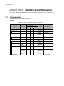
TABLE 2.1 Maximum installation number of components................................................................................................................... 28
TABLE 2.2 Available CPU ..................................................................................................................................................................... 33
TABLE 2.3 SB specifications ................................................................................................................................................................. 34
TABLE 2.4 MMB specifications ............................................................................................................................................................. 37
TABLE 2.5 (IOU_1GbE/IOU_10GbE) specifications ........................................................................................................................... 39
TABLE 2.6 The specification of the IOU built-in LAN Controller .......................................................................................................... 39
TABLE 2.7 Connection of IOU with DU ................................................................................................................................................ 42
TABLE 2.8 DU specifications ................................................................................................................................................................ 42
TABLE 2.9 HDD bays in the SB and the HDD specifications of the DU............................................................................................. 44
TABLE 2.10 The HDD capacity in maximum configuration, and the maximum LUN capacity in a RAID configuration.................. 44
TABLE 2.11 The SSD capacity in maximum configuration and the maximum LUN capacity in a RAID configuration ................... 45
TABLE 2.12 OPL specifications ............................................................................................................................................................ 47
TABLE 2.13 PCI_Box Specification ...................................................................................................................................................... 47
TABLE 2.14 PCI_Box components ...................................................................................................................................................... 51
TABLE 2.15 Number of connectable PCI_Boxes ................................................................................................................................ 51
TABLE 2.16 Usable number of PCI Express slots in maximum configuration ................................................................................... 55
TABLE 2.17 PCI Express slot (IOU) specifications .............................................................................................................................. 55
TABLE 2.18 PCI Express Slot (PCI_Box) specifications ..................................................................................................................... 56
TABLE 2.19 PSU_P Specifications....................................................................................................................................................... 58
TABLE 2.20 PSU_S Specifications....................................................................................................................................................... 58
TABLE 3.1 List of bundled software ...................................................................................................................................................... 60
TABLE 4.1 Power supply pattern .......................................................................................................................................................... 67
TABLE 4.2 PSU mounting location (PRIMEQUEST 2400E) .............................................................................................................. 67
TABLE 4.3 PSU mounting location (PRIMEQUEST 2800E/2800B) .................................................................................................. 67
TABLE 5.1 Maximum number of partitions for each model (PPAR) ................................................................................................... 74
TABLE 5.2 Partition granularity of components making up a partition (PPAR) .................................................................................. 75
TABLE 5.3 Relationship between DU and IOU connection ................................................................................................................ 75
TABLE 5.4 Partition configuration rule (component) ............................................................................................................................ 76
TABLE 5.5 Partition granularity of each component that makes up the partition (Extended Partitioning)......................................... 76
TABLE 5.6 Minimum and maximum configuration of Extended Partitioning ...................................................................................... 77
TABLE 6.1 System disk redundancy .................................................................................................................................................... 80
xxi
CA92344-0534-01
Preface
TABLE 8.1 List of SVS function manuals ............................................................................................................................................. 86
xxii
CA92344-0534-01
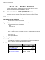
CHAPTER 1 Product Overview
1.1 Introduction of the PRIMEQUEST 2000 series
CHAPTER 1 Product Overview
This chapter describes the features, specifications, structural concept, system configuration, hardware
technologies, and software technologies of the PRIMEQUEST 2000 series.
1.1
Introduction of the PRIMEQUEST 2000 series
PRIMEQUEST 2000 series is a server with highest level scalability, availability and operability by
considering the newest Intel architecture as its basis. In particular, PRIMEQUEST 2000 incorporates server
integration and power-saving technologies, thereby contributing to cost savings and green ICT systems.
1.1.1 Features
The features of the PRIMEQUEST 2000 series are given below.
High reliability and high-performance
-
Use of Intel ® Xeon ® processor E7 v2 product family
-
SMP system with up to eight sockets (PRIMEQUEST 2800E/2800B)
High availability
-
The following are supported as the memory functions.
-
DDDC
-
Memory Patrol Scrub
-
Memory Mirror
-
Partial Memory Mirror
-
Memory Sparing
-
Support of degradation operation function so that the system can operate by isolating the faulty CPU
cores or SBs
-
Support of hardware RAID
-
Support of software RAID
-
Support of Reserved SB functions
Operations support function
-
Agentless (ServerView Agentless Service (SVAS)) hardware monitoring function
Maintainability
-
Provided with a Fault Location function to identify suspected components when hardware failure occurs
-
Support for maintenance operations by MMB Web-UI Maintenance Wizard
Flexibility
PRIMEQUEST
- Support of physical partitioning
(See, 5.2 Physical Partitioning (PPAR))
- Support of flexible I/O function
(See, 5.8 Flexible I/O Mode)
- Support of extended Partitioning
(See, 5.3 Extended Partitioning)
- Support of Dynamic Reconfiguration
(See, 5.7 Dynamic Reconfiguration
Function)
1
2400E
2800E
Supported
Supported
Supported
Supported
Supported
Supported
Supported
Supported
2800B
Not
Supported
Not
Supported
Not
Supported
Not
Supported
CA92344-0534-01
CHAPTER 1 Product Overview
1.2 Product Lineup
Virtualization support
-
Support of Intel ® Virtualization Technology (VT-x, VT-d)
-
Support of APIC virtualization (APICv)
Green compliance / Power saving
1.2
-
Control of power optimization
-
Control of the device cooling airflow with flap
-
Optimization of cooling by group partition in the cabinet
-
Support of power efficiency function (Optimal Power Allocation)
-
Use of low consumption devices (LV-DIMM and SSD)
-
Use of high efficiency power supply (80plus platinum)
-
Precision control of cooling fan rotation speed
-
Support of Power Saving function
-
Compliance with RoHS regulation (2011/65/EU)
Product Lineup
The PRIMEQUEST 2000 series includes the following models.
-
PRIMEQUEST 2400E: 4 sockets, Enterprise model
-
PRIMEQUEST 2800E: 8 sockets, Enterprise model
-
PRIMEQUEST 2800B: 8 sockets, Business model
The external view is shown below.
For details on the conceptual diagram, see ‘2.2 Base cabinet’.
FIGURE 1.1 External Overview of 2400E and 2800E
2
CA92344-0534-01
CHAPTER 1 Product Overview
1.2 Product Lineup
FIGURE 1.2 External Overview of 2800B
3
CA92344-0534-01
CHAPTER 1 Product Overview
1.3 PRIMEQUEST 2000 series configuration
1.3
PRIMEQUEST 2000 series configuration
The following figure shows a conceptual diagram of the configuration of the PRIMEQUEST 2000 series.
FIGURE 1.3 Configuration conceptual diagram
Remarks
IOU_10GbE and IOU_1GbE are collectively referred as IO units (IOU)
4
CA92344-0534-01
CHAPTER 1 Product Overview
1.3 PRIMEQUEST 2000 series configuration
1.3.1 Hardware configuration
Features of PRIMEQUEST 2400E
The features of the PRIMEQUEST 2400E are listed below.
-
Up to two CPUs can be mounted to each SB
-
Up to two SBs can be mounted
-
Up to 4 HDDs can be mounted to each SB
-
Up to four sockets SMP
-
Up to two physical partitions (PPAR)
-
Main hardware configuration
-
Number of connected IOUs: 4
-
Number of connected DUs: 2
-
Number of PCI_Boxes: 4
FIGURE 1.4 Hardware configuration image (PRIMEQUEST 2400E)
5
CA92344-0534-01
CHAPTER 1 Product Overview
1.3 PRIMEQUEST 2000 series configuration
6
CA92344-0534-01
CHAPTER 1 Product Overview
1.3 PRIMEQUEST 2000 series configuration
Features of the PRIMEQUEST 2800E
Features of the PRIMEQUEST 2800E are as below.
-
Up to 2 CPUs can be mounted to each SB
-
Up to 4 SBs can be mounted
-
Up to 4 HDDs can be mounted to each SB
-
Up to eight sockets SMPs
-
Up to four physical partitions (PPAR)
-
Main hardware configuration
-
Number of connected IOUs: 4
-
Number of connected DUs: 2
-
Number of PCI_Boxes: 4
FIGURE 1.5 Hardware configuration image (PRIMEQUEST 2800E)
7
CA92344-0534-01
CHAPTER 1 Product Overview
1.3 PRIMEQUEST 2000 series configuration
8
CA92344-0534-01
CHAPTER 1 Product Overview
1.3 PRIMEQUEST 2000 series configuration
Features of the PRIMEQUEST 2800B
Features of the PRIMEQUEST 2800B are as below.
-
Up to 2 CPUs can be mounted to each SB
-
Up to 4 SBs can be mounted
-
Up to eight sockets SMPs
-
Main hardware configuration
-
Number of connected IOUs: 4
-
Number of connected DUs: 2
FIGURE 1.6 Hardware configuration image (PRIMEQUEST 2800B)
9
CA92344-0534-01
CHAPTER 1 Product Overview
1.3 PRIMEQUEST 2000 series configuration
1.3.2 Hardware specifications
The hardware specifications of the PRIMEQUEST 2000 series are listed in the table below.
TABLE 1.1 Hardware specifications
PRIMEQUEST
2400E
Number of mounted SBs
Number of mounted IOUs
Number of mounted DUs
Number of mounted PCI_Boxes
CPU
Number of sockets
Maximum SMP
Socket Type
Supported CPU
Core / Socket
CPU clock
QPI rate
L1 cache
L2 cache
L3 cache
Virtual assist
Memory
Supported DIMM
Maximum capacity
Speed
Memory protection
function
Memory mirror
Memory spare
Maximum number of partitions (PPAR)
Dynamic Reconfiguration (DR)
Flexible I/O
Reserved SB
Internal disk
Number of SB built-in
slots
Number of DU built-in
slots
Maximum capacity
PCI Express slot
Built-in
(PCI Express Gen3)
2800E
2
4
4
4
4
4
2
2
2
4
4
Up to 4
Up to 8
Up to 8
4
8
8
Socket R1 (LGA 2011)
Intel® Xeon® processor E7 v2 product family (*1)
Up to 15 (*2)
Up to 3.40 GHz (*2)
Up to 8.0 GT/s (*2)
Instruction:32 KB/core, Data:32 KB/core
256 KB/core
Up to 37.5 MB/socket (*2)
Intel VT, Intel VT-d2
DDR3-RDIMM, DDR3-LRDIMM, 8GB /16GB/ 32GB/
64GB
6 TB (@64 GB) 12 TB (@64 GB)
1066 MT/s, 1333 MT/s, 1600 MT/s
ECC, SDDC, DDDC (in Lockstep mode)
Partial mirror / Full mirror
Supported
2
4
Supported
Supported
Supported
8
16
KVM interface (*4)
External USB
VGA
Video redirection function
1
-
8
19.2 TB
28.8 TB
Up to 16 (4x IOU_1GbE)
Max.
Up to 56
(PCI Express Gen3) (*3) (4x IOU_1GbE + 4x PCI_Box)
Onboard device
2800B
9.6TB
Up to 16
(4x IOU_1GbE)
Dual GbE (on IOU_1GbE) / Dual 10GbE (on
IOU_10GbE)
USB2.0 4 port (/SB)
25 pin analog -VGA 1 port (/SB)
Supported
10
CA92344-0534-01
CHAPTER 1 Product Overview
1.3 PRIMEQUEST 2000 series configuration
TABLE 1.1 Hardware specifications (continued)
PRIMEQUEST
2400E
2800E
2800B
Virtual media function
Supported
PSU, fan, HDD, PCI Express card, CLK, MMB (*5), power
Redundancy supported hardware
input system
PSU, fan, HDD, PCI Express card,
PSU, fan, HDD,
Hot replacement supported components
MMB (when duplication)
PCI Express card
1 (Duplication not
Number of installed MMBs
1 (Duplication is an option)
supported)
AC100 V/ 200-240
Input voltage
AC200-240 V
V
4 (200 V), 6 (100
Number of installed PSUs (maximum)
6
V)
Power redundancy support
N+1, N+N (Dual power feed)
External
Width
445 (17.52)
dimensions [mm Depth
782 (30.79)
(in.)]
Height
438 (17.25)
Number of occupied units
10U
143 (315)
Weight [kg(lb)]
124 (273)
150 (331)
*1: Since supported CPU differs depending on PRIMEQUEST model, see ‘2.3.1 Support CPU list’.
*2: Since these values differ depending on CPU model, see ‘2.3.1 Support CPU list’.
*3: When the maximum number of PCI_Boxes are connected.
*4: The KVM interface is provided for each SB (should not be always-on connection).
*5: Redundancy of MMB is supported in PRIMEQUEST 2400E and 2800E. PRIMEQUEST 2800B does not
support MMB redundancy.
For details on the device specifications, environment conditions and power conditions of the PRIMEQUEST
2000 series, see PRIMEQUEST 2000 series hardware installation manual (CA92344-0535).
1.3.3 Partition management
Partition is a divided unit of the hardware which is provided with the functions of processing device, having at
least one SB and IOU. Since partitions are independent hardware units, each partition can be considered as
an independent server. Multiple production system can be operated on a PRIMEQUEST 2000 by installing
different OS and applications in each partition.
The configuration of a partition of the PRIMEQUEST 2000 series can be changed by static configuration
control function (*1), and by dynamic configuration control function (*2).
*1: Function that turns on or turns off power in a partition unit, or changes its configuration triggered by
rebooting.
*2: Dynamic Reconfiguration (DR). Function which changes the partition resource configuration without
rebooting the partition which is the target for changing configuration.
For details on the partition functions, see ‘4.2.5 Partition settings and configuration display’.
1.3.4 Hardware management
The Management Board (MMB) is provided as a mechanism for managing the hardware of the entire
PRIMEQUEST 2000 series.
The MMB console (*1), the Field Support Tool (FST (*2)), and an external network can be connected
through a LAN connection from the MMB.
*1: Console for setting up and displaying each hardware resource
*2: Console for maintaining the hardware of the PRIMEQUEST 2000 series. Used by the field engineers.
The MMB has dedicated CPU which is independent of the CPU on the SB, and is mounted on the rear of the
cabinet.
The MMB controls and processes the following.
-
Partition configuration control in cabinet
-
Power control
-
Mirror mode settings
11
CA92344-0534-01
CHAPTER 1 Product Overview
1.4 Hardware technologies
-
Reset process
-
Sensor monitoring
-
Log management
- Schedule operations
Connecting the MMB to REMCS (remote client support system) by any of the following methods enables to
remotely monitor the status of the device.
1.4
-
Via the Web-UI from management network (usual)
-
Via the CLI where the management terminal is connected to the MMB serial port
Hardware technologies
This section describes the main functions provided in the PRIMEQUEST 2000 series.
Technology that attains high efficiency, high scalability (expandability)
-
Intel ® Xeon ® processor E7 v2 product family
-
QuickPath Interconnect (QPI)
-
Hyper threading-technology function
Technologies providing high-reliability and high-availability
-
DDDC
-
Memory Patrol Scrub
-
Memory Mirror function
-
Memory Sparing function
-
Reserved SB
-
Hardware RAID
-
PCI hot plug for PCI_Box
-
Security / Encryption function
-
TPM/BitLocker/TXT
Technologies providing flexible operability
-
Physical partitioning (PPAR)
-
Extended Partitioning
-
Dynamic Reconfiguration (DR)
-
Flexible I/O
-
Virtualization support function (Virtualization Technology)
-
Enhanced Speed Step/Turbo Boost function
-
Management Board (MMB)
-
Network (LAN)
-
Preboot eXecution Environment (PXE)
-
iSCSI boot and iSCSI connection
-
FcoE boot and FCoE connection
-
Wake on LAN (WOL)
Technologies that facilitate administration
-
Centralized management of hardware with MMB
-
Agentless (ServerView Agentless Service (SVAS)) hardware monitoring
12
CA92344-0534-01
CHAPTER 1 Product Overview
1.4 Hardware technologies
Remarks
SVAS should be installed to monitor for any error in the PCI Express card (*1).
*1: Since firmware monitor SAS RAID controller cards, monitoring SAS RAID controller cards and HDD or
SSD can be done without installing SVAS.
1.4.1 CPU
The CPU is mounted with the Intel ® Xeon ® processor E7 v2 product family in the PRIMEQUEST 2000
series.
In all models, a mix installation of CPU having different number of cores is supported in a cabinet, as long as
those CPUs are restricted to the product number supported by the respective model.
For details on the conditions of mix installation of CPUs in the cabinet, see ‘G.1 CPU’ of “PRIMEQUEST
2000 Series Administration Manual” (CA92344-0537).
Hyper Threading Technology Function
The PRIMEQUEST 2000 series supports the Hyper Threading Technology function.
For details on the Hyper Threading Technologies functions, see ‘1.4.3 Hyper Threading Technology
Function’.
Intelligent Power Technologies
The PRIMEQUEST 2000 series supports the following Intelligent Power Technologies.
-
Enhanced Halt State
This function reduces the CPU power consumption by lowering the core/ clock frequency ratio and core
voltage of the CPU in the idle mode, according to the instructions of the OS.
-
Demand Based Switching
This function changes the combination of operating voltage and the clock of the CPU, called the P-State
to reduce the power consumption.
-
Turbo Boost Technology
When more than one CPU core is idle, this function increases the frequency of the running CPU core to
a higher than specified frequency, within the Thermal Design Power (TDP) range.
Enhanced Speed Step
Enhanced Speed Step is a function that changes the operating frequency according to the load of each core
in the CPU. It has the following features.
-
Each socket in the partition can have different frequency each other.
-
Cores in the Socket can have only same frequency.
The default value is “enabled”
1.4.2 QuickPath Interconnect (QPI)
The PRIMEQUEST 2000 series uses a high-speed system bus called Intel ® Quick Path Interconnect (QPI)
to communication between CPUs in a partition.
The resource can be increased by connecting peer CPUs by the QPI.
1.4.3 Hyper Threading Technology Function
PRIMEQUEST 2000 series supports the function of hyper-threading technology. In hyper threading
technology function, a single processor core does the work of multiple processor cores when viewed from
the OS, thereby improving CPU performance.
This function supports up to two threads per core and up to 30 threads for each CPU (15 cores).
Enabled/disabled of the [Hyper-Threading] is set from the [CPU configuration] menu of the UEFI.
-
Enabled (Default value)
- Disabled
For details on the hyper threading technology function settings, see ‘3.4.4 [CPU Configuration] menu’ in the
“PRIMEQUEST 2000 Series Tool Reference” (CA92344-0539).
13
CA92344-0534-01
CHAPTER 1 Product Overview
1.4 Hardware technologies
1.4.4 Memory Mirror Functions
The memory is duplicated and the data is written to both of duplicated memories. Even if an uncorrectable
error occurs in one memory, the data in the other memory can be used. This prevents the data errors which
cannot be corrected by Error Checking Correction (ECC), such as multi-bit error, which attains a continuous
and stable system operation.
In the PRIMEQUEST 2000 series, the Memory Mirror function is selected from the following Memory
Operation Mode.
-
Full Mirror Mode: All memory in all SB of specific partition is mirrored.
-
Partial Memory Mirror: The memory included in only the Home SB of the partition is duplicated.
Using the Memory Mirror, the partition can keep operating even if duplicated memory fails. The failed
memory will be removed from the partition (memory degradation) at next reboot. The operation when there is
memory degradation due to a memory fault can be selected from the following.
-
Mirror Keep Mode: The memory duplication is maintained even after memory degradation.
-
Capacity Keep Mode: The memory capacity is maintained by cancelling the memory duplication either
partially or in full.
For the details on the Memory Mirror function, see ‘3.2.5 Memory Mirror’ in “PRIMEQUEST 2000 Series
Administration Manual” (CA92344-0537).
1.4.5 Memory Sparing Function
The PRIMEQUEST 2000 series is provided with a Memory Sparing function.
The Memory Sparing function prepares spare rank (a rank means unit of the block of memory module.) to
endure rank errors. If predictive failure of a rank is detected, copying the data of the rank into the spare rank
not to use failed rank will be able to keep the partition operating.
The Memory Spare function is enabled by the MMB Web-UI.
Note
In Intel® Xeon® processor E7 v2 product family, Memory Sparing between CPU sockets and between DDR
Channels is not supported. When using Memory Sparing, it is necessary to mount the DIMM in such a way
so as to have multiple Ranks in a DDR Channel. If Memory Spare Mode is selected at the order placement,
corresponding PRIMEQUEST systems are shipped in such a way so as to fulfil this condition.
1.4.6 Reserved SB Function
PRIMEQUEST 2400E and 2800E models support Reserved SB function.
The Reserved SB function is the function where a faulty SB is automatically removed from the partition, and
the Reserved SB which is previously configured is added to a partition when the partition is powered on.
SB reserved for switching at the time of failure, is called Reserved SB. Since the partition is automatically
reconfigured / restarted, there is improved operation continuity.
For details on the Reserved SB function, see ‘3.2.3 Reserved SB’ in “PRIMEQUEST 2000 Series
Administration Manual” (CA92344-0537).
1.4.7 Hardware RAID
The PRIMEQUEST 2000 series supports hardware RAID. The hardware RAID has a dedicated RAID
controller chip and firmware. It can independently control an array by disconnecting the hard disk where
error had occurred, and connecting a spare disk or new normal hard disk.
The RAID levels supported by the hardware RAID are RAID 0, RAID 1, RAID 5, RAID 6, RAID 1E, RAID 10,
RAID 50, and RAID 60.
In SAS RAID controller card, a dedicated super-capacitor can be connected. The Write performance of RAID
5 and RAID 6 can be improved by enabling the Write Back Cache.
The SAS RAID controller card necessary for the hardware RAID should be mounted in the SB and DU.
Below table shows the number of HDD/SSD that is connected to a SAS RAID controller card in the DU and
shows
The number of HDD / SSD that can be mounted for each SAS RAID controller card in the DU is listed in the
table below.
14
CA92344-0534-01
CHAPTER 1 Product Overview
1.4 Hardware technologies
TABLE 1.2 Hardware RAID Level
Component
SB/DU
Installation RAID
Number of connected
card
HDDs/SSDs
SAS RAID controller 1
card
2
3
4
Hardware RAID level
RAID 0
RAID 0, RAID 1
RAID 0, RAID 1, RAID 5, RAID 6
RAID 0, RAID 5, RAID 6, RAID 1E, RAID 10
When two SAS RAID controller cards are installed in a DU, there would be up to two HDDs connected to a
SAS RAID controller card.
Activation of HDD/SSD can be increased even when using a hardware RAID.
For details, see ‘Modular RAID Controller/ Modular SAS HBA’, ‘MegaRAID SAS Software’ and ‘MegaRAID
SAS Device Driver Installation’.
1.4.8 PCI Hot Plug Function
All PCI Express slots in the PCI_Box of the PRIMEQUEST 2000 series support the PCI hot plug function.
This function is a technology that enables extraction or insertion of a PCI card during system operation.
Any PCI Express Slots in the IOU_1GbE and the IOU_10GbE do not support the PCI hot plug function.
1.4.9 Security and Encryption Function
The following security/ encryption function s are supported in the PRIMEQUEST 2000 series.
-
Advanced Encryption Standard New Instructions (AES-NI)
-
Digital Random Number Generator (DRNG)
- Supervisor Mode Execution Protection (SMEP)
For details on the security functions related to TPM related security, see ‘1.4.10 Trusted Platform Module
(TPM)’
1.4.10 Trusted Platform Module (TPM)
Trusted Platform Module (TPM) is supported in the PRIMEQUEST 2000 series.
Remarks
To use TPM, System Boards with TPM is required to be purchased.
Reserved SB function cannot be used if TPM function is enabled. The TPM is a security chip with the
following functions.
-
Data (storage) encryption processing function
-
Secret key storage function
- Platform certification
The TPM is enabled by UEFI to enable its function.
The BitLocker and Trusted Execution Technology (TXT) can be used by enabling the TPM.
For details, see ‘3.4.12 [Security Configuration] menu’ in “PRIMEQUEST 2000 Series Tool Reference”.
1.4.11 Physical Partitioning (PPAR)
The Physical partitioning divides the hardware resource into multiple systems within the cabinet and
operates independent systems (OS) as divided units.
The PRIMEQUEST 2000 series supports physical partitioning except for PRIMEQUEST 2800B.
The physical partition with any number of resources can be configured by using the flexible I/O mode (*1) in
all models.
*1: For details on the flexible I/O mode, see ‘5.8 Flexible I/O Mode’.
The following are the features of the partitioning function.
-
Multiple operations can be configured in the same cabinet, thus enabling a flexible system operation.
-
Hardware protection to prevent faults in the arbitrary partitions from affecting the other partitions.
15
CA92344-0534-01
CHAPTER 1 Product Overview
1.4 Hardware technologies
For details, see ‘5.2 Physical Partitioning (PPAR)’.
1.4.12 Extended Partitioning
The PRIMEQUEST 2400E/2800E supports the Extended Partitioning function.
The Extended Partitioning function is the function which divides the physical partition by firmware in units of
CPU core. Low cost, high reliability and secure procedures are provided.
The features of this function are listed below.
-
The granularity of the resource allocation to the partition is fine, thereby enabling effective usage of the
server resources.
-
The CPU can be allocated in units of core.
-
The memory can be allocated by one GB.
-
Easier to set up than virtualization OS
-
A device in the partition can be directly accessed from the CPU, without using a virtual device
The hardware resource allocation by using Extended Partitioning can be set in the MMB Web-UI.
For details, see ‘5.3 Extended Partitioning’.
1.4.13 Dynamic Reconfiguration (DR) function
The DR function changes the resource configuration of a partition without rebooting the partition.
The PRIMEQUEST 2400E/2800E supports the dynamic reconfiguration function.
Remarks
The DR function operates only for the physical partition.
For detail on the target of the DR function and OS supporting DR, see ''Table 3.12 DR Supported list' in 3.2.1
Dynamic Reconfiguration (DR)' in PRIMEQUEST 2000 Series Administration Manual (CA92344-0537)
1.4.14 Flexible I/O
The Flexible I/O can configure a physical partition by combining any SB and IOU irrespective of the
mounting location.
The PRIMEQUEST 2400E/2800E supports Flexible I/O.
For details, see ‘5.8 Flexible I/O Mode’.
1.4.15 Virtual Support Virtualization Technology (VT) Function
PRIMEQUEST 2000 series supports the Virtualization Technology (VT) listed in the table below.
TABLE 1.3 VT
VM Support
VT-x
Components
CPU
VT-c
IO-AT
Remarks
Intel ® CPU Virtualization technology
'VMX root mode and VMX non-root mode' are added in the existing
processor mode (rings from 0 to 3)
The merit of VT-x is low overheads of issue of privilege command by
Guest OS.
Intel ® Virtualization technology
VT-c is the general term for the virtualization support functions (VM
Assist) listed below.
CPU
I/O Acceleration Technology (IO-AT)
On board LAN IO-AT indicates high speed I/O technology, which increases the
controller
speed and efficiency of processing data and interruption.
- Intel (R) QuickData Technology
- Direct Cache Access (DCA)
- Extended Message Signaled Interrupts (MSI-X)
- Receive Side Coalescing (RSC)
- Low Latency Interrupts
16
CA92344-0534-01
CHAPTER 1 Product Overview
1.4 Hardware technologies
VMDq
SR-IOV
On board LAN Virtual Machine Device Queues (VMDq)
controller
VMDq is a virtualization support mechanism provided in the Intel LAN
card. The hardware with VMDq contains a function that creates the
LAN-SW on the VMM when the NIC is shared by multiple VMs.
On board LAN Single Root– IO Virtualization
controller
The SR-IOV is a PCI Express standard, having multiple functions in
the card, which directly accesses the respective functions from the
VM.
1.4.16 Management Board (MMB)
Management Board functions: Monitoring the hardware status, displaying configuration / error information,
partition management, network environment management and power control.
At least one MMB is required for operating the system in the PRIMEQUEST 2000 series. One more MMB
can duplicate the MMB in PRIMEQUEST 2400E and 2800E; even if one of the MMBs fail, the process can
be continued with the other MMB.
Active maintenance can be carried out in an operation with duplicate MMBs.
For details on the MMB, see ‘2.6 MMB (Management Board)’.
1.4.17 Network (LAN)
The PRIMEQUEST 2000 series has the following network (LAN) functions.
-
LAN port (IOU_1GbE)
The GbE interface of the GbE controller that is mounted on the IOU_1GbE, externally outputs the data
with a RJ-45 connector. It is supported in 1000BASE-T.
-
LAN port (IOU_10GbE)
The 10GbE interface of the 10GbE controller that is mounted on the IOU_10GbE, externally outputs the
data with a RJ-45 connector. It is supported in 10G BASE-T.
-
USER port (MMB #0 and #1 port)
Port for connecting to an external terminal for operating and monitoring various MMB functions via the
LAN. It is supported in 1000BASE-T.
-
REMCS port ([REMOTE] port on MMB)
This is a LAN port for REMCS. The port supports 100BASE-TX.
-
CE port (MMB [LOCAL] port)
This port is dedicated to connecting maintenance terminal used by field engineers. It is supported in
100BASE-TX.
17
CA92344-0534-01
CHAPTER 1 Product Overview
1.4 Hardware technologies
1.4.18 Preboot eXecution Environment (PXE)
The PRIMEQUEST 2000 series supports the PXE boot through LAN port on the IOU. It does not support
PXE boot functions through other LAN ports or the PCI Express card.
The PXE enables remote management operations, such as system startup and installation and updating of
the operating system. The following table shows whether the PXE boot is supported or not in each port.
TABLE 1.4 PXE boot support (external)
PXE Support
Component
Port
Legacy
IPv4
MMB
IOU_1GbE/
IOU_10GbE
User port
(Management 1000Base-T
LAN)
REMCS port
100Base-TX
CE port
100Base-TX
LAN port
1000Base-T
(IOU_1GbE)
LAN port
10GBase-T
(IOU_10GbE
PCI Express slot
PCI Express slot
PCI_Box
Remarks
Internal ports are not supported.
EFI
IPv6
IPv4
IPv6
-
-
-
-
Supported
-
Supported
Supported
Supported
-
Supported
Supported
-
-
-
-
18
CA92344-0534-01
CHAPTER 1 Product Overview
1.4 Hardware technologies
1.4.19 iSCSI boot and iSCSI connection
The PRIMEQUEST 2000 series supports iSCSI boot and iSCSI connections.
TABLE 1.5 iSCSI boot
iSCSI boot
Component
Port
Legacy
IPv4
MMB
User port
(Management
LAN)
REMCS port
IOU_1GbE/
IOU_10GbE
PCI_Box
EFI
IPv6
IPv4
IPv6
1000Base-T
-
-
-
-
100Base-TX
-
-
-
-
CE port
100Base-TX
Operation port
1000Base-T
(LAN port)
(IOU_1GbE)
Operation port
10G Base-T
(LAN port)
(IOU_10GbE)
PCI Express slot
-
-
-
-
Supported
-
Supported
Supported
Supported
-
Supported
Supported
Supported
-
Supported
Supported
PCI Express slot
Supported
-
Supported
Supported
TABLE 1.6 iSCSI connections
iSCSI connection
Component
Port
Legacy
IPv4
MMB
IOU_1GbE/
IOU_10GbE
PCI_Box
EFI
IPv6
IPv4
IPv6
User port
(Management
LAN)
REMCS port
1000Base-T
-
-
-
-
100Base-TX
-
-
-
-
CE port
100Base-TX
-
-
-
-
Operation port
1000Base-T
(LAN port)
(IOU_1GbE)
Operation port
10G Base-T
(LAN port)
(IOU_10GbE)
PCI Express slot
Supported
Supported
Supported
Supported
Supported
Supported
Supported
Supported
Supported
Supported
Supported
Supported
PCI Express slot
Supported
Supported
Supported
Supported
Note
Internal ports are not supported.
19
CA92344-0534-01
CHAPTER 1 Product Overview
1.4 Hardware technologies
1.4.20 FCoE boot and FCoE connection
PRIMEQUEST 2000 series supports FCoE boot and FCoE connections.
TABLE 1.7 FCoE boot
FCoE boot
Component
MMB
Port
User port
(Management LAN)
REMCS port
IOU_1GbE/
IOU_10GbE
PCI_Box
PCI Express slot
EFI
IPv4/IPv6
-
-
100Base-TX
-
-
100Base-TX
1000Base-T
-
-
10G Base-T
-
-
CNA card
Supported
Supported
1000Base-T
CE port
Operation port
(LAN port)
(IOU_1GbE)
Operation port
(LAN port)
(IOU_10GbE)
PCI Express slot
Legacy
IPv4/IPv6
Except for CNA Card -
-
CNA card
Supported
Supported
Except for CNA Card -
-
TABLE 1.8 FCoE connections
FCoE connection
Component
MMB
IOU_1GbE/
IOU_10GbE
PCI_Box
Port
Legacy
EFI
IPv4/IPv6
IPv4/IPv6
User port
(Management LAN)
REMCS port
1000Base-T
-
-
100Base-TX
-
-
CE port
Operation port
(LAN port)
(IOU_1GbE)
Operation port
(LAN port)
(IOU_10GbE)
PCI Express slot
100Base-TX
1000Base-T
-
-
10G Base-T
-
-
CNA card
Supported
Supported
PCI Express slot
Except for CNA Card -
-
CNA card
Supported
Supported
Except for CNA Card -
-
Note
Internal ports are not supported.
20
CA92344-0534-01
CHAPTER 1 Product Overview
1.4 Hardware technologies
1.4.21 Wake on LAN (WOL)
WOL is a function that turns on the power from remote control.
The PRIMEQUEST 2000 series supports WOL in all the LAN ports on the IOU.
WOL is enabled in any LAN card that is mounted in the Onboard LAN port and the PCI Express slot.
However, enabling WOL from an Onboard LAN port of the IOU requires setup by MMB Web-UI.
For details, see '1.3.7 [Partition #x] menu' in "PRIMEQUEST 2000 Series Tool Reference” (CA92344-0539).
TABLE 1.9 WOL Support
WOL
Component
Port
Legacy
EFI
IPv4/IPv6
MMB
IOU_1GbE
IOU_10GbE
PCI_Box
IPv4/IPv6
User port
(Management LAN)
REMCS port
1000Base-T
-
-
100Base-TX
-
-
CE port
100Base-TX
-
-
Operation port (LAN Port)
PCI Express slot
Low Profile
Operation port (LAN Port)
1000Base-T
Supported
Supported
Supported
Supported
Supported
Supported
PCI Express slot
10G Base-T
Supported
Supported
PCI Express slot
-
-
Note
Internal ports are not supported.
1.4.22 sadump
sadump is provided in the PRIMEQUEST 2000 series (except for PRIMEQUEST 2800B) to improve quality
of PRIMEQUEST systems using Red Hat Enterprise Linux. (*1)
The memory dump can be acquired by executing sadump when error occurs irrespective of the status of the
RHEL that is operating in the PRIMEQUEST 2000 series. Then, investigation of the cause of error and
support becomes possible thereby receiving a high degree of support.
(*1) sadump is not supported on SUSE Linux Enterprise Server.
1.4.23 Green Support and Power Saving Technology
The PRIMEQUEST 2000 series provides power saving functions which help reduce power consumption for
relevant configuration with technology that is supported in the customer’s operating environment, such as
workload integration and business schedule, integration.
- Optimization of cooling by group partition in the cabinet
Achieving optimization by carefully controlling the fan rotational speed for each cooling group
- Reduction of power consumption
Using low power consumption devices (LV-DIMM, SSD), and high efficiency power (80 PLUS
PLATINUM).
With Power Saving functions, performance tuning takes place automatically when the power
consumption approaches the maximum preset value.
- Control of the device cooling airflow with flap
The flap in the cabinet is opened and closed by inserting and removing SB, DU, IOU, PSU or FANU,
which can efficiently control cooling airflow.
-
Based on RoHS Regulations (2011/65/EU)
1.4.24 Active Processor Cores Function
The PRIMEQUEST 2000 series supports Active Processor Cores
Active Processor Cores limits the number of cores for specific physical partition.
Active Processor Cores is also called as Core Disabling or Logical Processor Disable.
21
CA92344-0534-01
CHAPTER 1 Product Overview
1.4 Hardware technologies
Active Processor Cores is configured by the UEFI.
The default value is ‘All Cores Enabled’.
TABLE 1.10 Active Processor Cores specifications
Item
Specifications
Default value
All cores are enabled.
Minimum number of enabled cores
One core for each socket is enables.
Specifying enabled cores
The number of enabled cores is specified.
Hyper Thread setting
Setting Enable/Disable of Hyper thread function.
Note
The setting that Hyper Thread is made enabled or disabled is applied to all active cores of all CPU in the
partition.
For details, see ’3.4.4 [CPU Configuration] Menu’ in “PRIMEQUEST 2000 Series Tool Reference”
(CA92344-0539).
1.4.25 Optimal Fan Control Cooling (Optimization of rotation per minute
of fans)
The PRIMEQUEST 2000 series supports Optimal Fan Control Cooling function.
This function optimizes fan rotational speed so that system is cooled efficiently while reducing power
consumption.
Optimal Fan Control Cooling function below:
-
Determines the rpm of the fan, considering both the Ambient and the Component temperature of the
place where the system is set and configuration pattern of the system.
-
There is the concept of cooling group in a cabinet, which controls fan rotational speed for each group.
For details on cooling, see ‘2.15 Fan (Cooling mechanism)‘.
1.4.26 Air Flow Monitoring
The PRIMEQUEST 2000 series supports the Air Flow Monitoring function.
The Air Flow Monitoring provides the following functions.
-
The exhaust volume is displayed in the MMB Web-UI
-
The exhaust volume is notified to the higher level software through the SNMP.
1.4.27 Optimal Power Allocation (Optimization of the number of
operation power sources)
The PRIMEQUEST 2000 series supports Optimal Power Allocation as one of the energy saving functions.
The following operations are performed in Optimal Power Allocation.
- Optimization of the number of operating PSUs
Changing the number of operating PSUs based on the configuration of the device.
- Optimization of the number of operating DDCs
Changing the number of operating DDCs based on the number of CPUs mounted in the SB.
Optimal Power Allocation operates automatically according to the configuration of the device. There is no
screen for setting.
Remarks
If redundantly configured PSU turns non-redundant due to PSU failure, Optimal Power Allocation does not
operate.
1.4.28 Power Consumption Monitoring
The PRIMEQUEST 2000 series supports Power Consumption Monitoring.
22
CA92344-0534-01
CHAPTER 1 Product Overview
1.5 Software technologies
Power Consumption Monitoring is a function that displays the power consumption of the main unit and the
PCI_Box of the PRIMEQUEST 2000 series.
Power consumption updated periodically is displayed in the MMB Web-UI. It is linked with the Systemwalker
Centric Manager, which is operation management software, and the power consumption is displayed as a
graph. Therefore, it is to effectively control power consumption of data center.
TABLE 1.11 Power Consumption Monitoring Support
Target
MMB Web-UI
SNMP (MIB)
Main unit
Supported
Supported
PCI_Box
Supported
Supported
1.4.29 Power Saving
Power Saving is a function that automatically adjusts the system operation when its power consumption
closes to pre-determined upper limit such that power consumption of the system does not exceed the
maximum value that has been set.
All models of PRIMEQUEST 2000 series supports the Power Saving function.
1.4.30 Agentless Monitoring
Agentless monitoring is supported in the PRIMEQUEST 2000 series.
Agentless monitoring is a function that reduces the use of agent software on OS and monitors the server by
the hardware.
It is necessary to install the SVAS if PCI Express card should be monitored (*1).
*1: SVAS does not monitor SAS RAID controller card. Since BMC firmware and MMB firmware monitor SAS
RAID controller cards, monitoring SAS RAID controller cards can be done without installing SVAS.
1.5
Software technologies
The PRIMEQUEST 2000 series uses the following types of software to increase reliability, availability, and
operability.
-
Firmware
-
Operating system and virtualization software
-
Server management software
-
Fujitsu middleware products
-
Clustering
1.5.1 Firmware
The PRIMEQUEST 2000 series has the following firmware embedded for hardware management and
operation.
- UEFI (BIOS) firmware
The PRIMEQUEST 2000 series uses UEFI (United Extensible Firmware Interface) firmware, which is
becoming an industry standard. The UEFI firmware has the BIOS setup menu that enables various types
of settings.
The UEFI has a variety of functions. They include functions for loading various UEFI drivers, diagnosing
and initializing memory areas for the operating system, performing write/read diagnosis of various I/O
registers, selecting a boot device, and setting the boot device order. Moreover, the Extended Partitioning
function is installed in the UEFI firmware (*1). For the details, see ‘5.3 Extended Partitioning’.
*1: Extended Partitioning is a function which runs on firmware, similar to the partition function (PPAR)
running on hardware. Different from the VMware, device virtualization is not carried out. OS handles
hardware resources divided by firmware as a hardware device within the partition. The granularity of the
partition consists of physically segmented hardware units (CPU core, DIMM Module, and I/O Device).
- BMC firmware
BMC firmware is provided with the functions for communicating with firmware, OS, and the MMB
firmware to realize physical partition and Extended Partitioning.
Included functions are:
23
CA92344-0534-01
CHAPTER 1 Product Overview
1.5 Software technologies
-
-
Console redirection
-
Video direction function
-
Virtual media function
Function corresponding to the remote storage function before the PRIMEQUEST 2000 series.
-
Interface between the software in the higher level layers
MMB firmware
MMB firmware manages entirely all models of PRIMEQUEST 2000 series.
Included functions are:
-
System management function
-
Hardware monitoring
-
Power control, system initialization
-
Mirror mode setup and partition configuration control
-
Web-UI function for system management
-
User authority management
-
Time synchronization
-
Scheduled power on and off operation
-
Maintenance/ update function of each firmware
-
Save/restore of the setup information
-
Reserved SB function setup
-
Firmware update while the partition is operating. (*1)
(*1) It is the time when the partition is turned off that updated firmware is applied.
1.5.2 Operating system and virtualization software
-
Windows
PRIMEQUEST 2000 series supports Windows Operating systems such as Windows Server 2012 R2.
Hyper-V is available with all of Windows OS supported by PRIMEQUEST 2000 series.
- Linux
PRIMEQUEST 2000 series supports Linux operating systems such as Red Hat Enterprise Linux and
SUSE Linux Enterprise Server.
PRIMEQUEST 2000 series also supports KVM adopted in Red Hat Enterprise Linux and SUSE Linux
Enterprise Server.
- VMware
PRIMEQUEST 2000 series supports VMware vSphere 5 as a virtualization platform.
To consolidate mission critical applications using VMware, PRIMEQUEST 2000 series with its high
reliability is the best matched platform.
For details on operating systems supported by PRIMEQUEST 2000 series, see 3.2 OS.
1.5.3 Server management software
The following server management software is a standard bundle in the PRIMEQUEST 2000 series.
-
ServerView Agentless Service (SVAS)
-
ServerView Suite (SVS)
-
Operations management software
ServerView Agentless Service (SVAS)
The SVAS is a software component installed in the OS. It monitors the PCI Express card (*1). When an error
is detected, it is reported through MMB.
*1: Since firmware monitor SAS RAID controller cards, monitoring SAS RAID controller cards can be done
without installing SVAS.
Note
24
CA92344-0534-01
CHAPTER 1 Product Overview
1.5 Software technologies
If SV Agent is installed, it is not required to install SVAS.
ServerView Suite (SVS)
The SVS provides following functions, all of them are bundled as standard products:
-
ServerView Installation Manager (SVIM)
-
ServerView Operations Manager (SVOM)
-
ServerView Agent (SV Agent)
-
ServerView RAID Manager (SV RAID)
-
ServerView Mission Critical Option (SVmco)
The SVS manages the PRIMEQUEST 2000 series in the following configuration.
FIGURE 1.7 Configuration diagram of the PRIMEQUEST 2000 series operation management
ServerView Installation Manager (SVIM)
SVIM allows the user to easily perform the setup operations, including the OS installation during the initial
installation or reconfiguration of a server.
SVIM much simplifies steps for hard disk RAID configuration and driver selection to the extent that even
users without expertise can implement a setup easily and securely in a short time. Setting up using the SVIM
results in a stable operation early, at the beginning of an operation.
25
CA92344-0534-01
CHAPTER 1 Product Overview
1.5 Software technologies
FIGURE 1.8 SVIM setup flow
Item
Automatic HDD
RAID configuration
Optimal driver installation
Guidance on bundled software
Hot fix application
Description
You can configure RAID using configuration tool called
WebBIOS. This tool is started after power-on and start of OS.
SVIM can simplify setup for a RAID. You only need to enter
information such as the RAID type, combination of HDDs, and
spares, even if without having the knowledge on how to
operate the RAID configuration tool.
The capacity of each compartment/partition can also be set.
General-purpose drivers and model-specific drivers exist even
for the same hardware. SVIM selects and installs the best-fit
driver for each model, so that the drivers do not cause any
problems after operation begins.
SVIM supports installation of the high-reliability tools, including
the hardware monitoring tool (ServerView) and RAID
management/monitoring tool (SV RAID) that must be installed.
Once a selection is made from the group of software products,
SVIM automatically installs the selected tool from the
CD/DVD.
SVIM applies an ‘emergency’ level hot fix for the operating
system. This prevents the occurrence of known faults and
promotes stable operation.
ServerView Operations Manager (SVOM)
SVOM identifies hardware faulty parts, displays diagnosis on the console, and sends e-mail to the
administrator to support early recovery and stable operation.
ServerView Agent (SV Agent)
SV Agent monitors the status of the hardware and the operating system, and instructs operation from the
SVOM.
ServerView RAID Manager (SV RAID)
SV RAID is the management tool that monitors, manages, maintains, and configures the array controller and
the hard disks and logical drives connected to the RAID controllers.
ServerView Mission Critical Option (SVmco)
SVmco cooperates with PRIMECLUSTER or Primesoft Server to acquire the status of each partition and
stop the partition forcibly. SVmco is needed if you use PRIMECLUSTER or Primesoft Server.
26
CA92344-0534-01
CHAPTER 1 Product Overview
1.5 Software technologies
1.5.4 Fujitsu middleware products
A high-reliability and high-availability system can be constructed by combination of PRIMQUEST and Fujitsu
middleware products below.
-
Interstage
Application server, Web service, report, Java development environment, business intelligence
-
Systemwalker
Business service management, operation service management, life cycle management, security
management, resource management, job management, resource control, network management.
Systemwalker displays graph for the power consumption of entire server and PCI_Box by Power
Consumption Monitoring function.
As long as virtualization software environment provides the function that is compatible with the physical
hardware environment, Fujitsu middleware can operate on a guest OS. Operation on virtual software might
not be assured depending on the middleware or operation pattern.
1.5.5 Clustering
Red Hat Enterprise Linux (RHEL) supports clustering with PRIMECLUSTER (Fujitsu middleware).
Windows Server 2012 R2, Windows Server 2012 and Windows Server 2008 R2 support the clustering with
Failover Cluster (OS standard function).
Using clustering can improve the availability of the entire system.
Clustering produces high availability in such a way that even if a fault occurs in the active partition or cabinet,
a standby partition or cabinet can take over job operations.
Through automatic detection of faults in important system resources ranging from hardware and middleware
to applications and autonomous control, such as failover, clustering enables the system to continue secure
operations. Clustering also enables autonomous control such as failover.
The service uptime is greatly improved because periodic maintenance or system reconfiguration (during a
scheduled downtime) can be performed without affecting the resources in use.
27
CA92344-0534-01
CHAPTER 2 Hardware Configuration
2.1 Components
CHAPTER 2 Hardware Configuration
This section describes the PRIMEQUEST 2000 series hardware configuration, system specification and
each component specification.
2.1
Components
The table below lists the hardware components.
Remarks
The hierarchy in the component column represents an inclusive relationship.
TABLE 2.1 Maximum installation number of components
Component
Granularity
PSU
PSU_P/PSU_S
FANM
Per system
FANU
Per system
FANM
Per PSU
Per FANU
SB
Per system
CPU
Per SB
DIMM
Per SB
(Except
Mezzanine)
Per SB
Mezzanine
DIMM
SAS RAID
controller card
Maximum number
mounted
PRIMEQUEST
Display
format
2400E 2800E 2800B
6
6
6
PSU#0,
PSU#5, etc.
2
2
2
FANM#0,
FANM#1
3
3
3
FANU#0,
FANU#5,
etc.
2
2
2
FANM#0,
FANM#1
2
4
4
SB#0,
SB#3, etc.
2
2
2
CPU#0,
CPU#1
24
24
24
DIMM#0A0,
DIMM#1B
5, etc.
2
2
2
Mezz#0,
Mezz#1
Redundancy
configuration
Possible by option
Possible
as standard
Possible by option
Possible
as standard
Possible by option
No
Possible by option
No
Per
Mezzanine
12
12
12
DIMM#0C0, No
DIMM#1D5,
etc.
Per SB
1
1
-
PCI Slot
28
Possible by
software RAID
CA92344-0534-01
CHAPTER 2 Hardware Configuration
2.1 Components
TABLE 2.1 Maximum installation number of component list (continued)
Component
Maximum number
mounted
PRIMEQUEST
Granularity
Redundancy
configuration
Display
format
2400E 2800E 2800B
Per SB
1
1
HDDBP
HDD/ SSD
1
4
1
4
-
TPM
1
1
1
1
4
1
4
1
4
4
4
4
0
4
0
4
0
4
Per
1
IOU_10GbE
2
Per system 2
1
1
2
2
2
2
Per DU
2
2
2
2
2
2
4
4
4
Per system
2
2
1
Micro SD
Per MMB
1
1
1
DU#0,DU#1 Possible by
software RAID
Main
No
Board#0,
Main
Board#1
Possible by
PCI Slot
software RAID
HDD#0,
Possible by option
HDD#3, etc.
MMB#0,
Possible by option
MMB#1
Micro SD
No
BATTERY
FBU
BATTERY
IOU_1GbE (*1)
PCI Express
slot (*2)
Per system
LP
FH
IOU_10GbE (*1)
PCI Express
slot (*2)
Per
IOU_1GbE
Per system
LP
FH
DU
Main Board
SAS RAID controller
card
HDD/ SSD
MMB
FBU
No
HDDBP
No
HDD#0,
Possible by option
HDD#3, etc.
TPM
No
Battery
IOU#0,I
OU#3, etc.
PCIC#0,
PCIC#3, etc.
No
Possible by option
(*3)
Possible by option
(*3)
IOU#0,
IOU#3, etc.
PCIC#0,
PCIC#2, etc.
Possible by option
(*3)
Possible by option
(*3)
Per MMB
1
1
1
Battery
No
OPL
Per system
1
1
1
OPL
No
MP
Per system
1
1
1
MP
No
PDB
Per system
2
2
2
PDB
No
*1: In the PRIMEQUEST 2400E/2800E/2800B, one to four units per system can be mounted.
*2: LP is the abbreviation of Low Profile and FH is the abbreviation is Full Height.
*3: PCI Express card can be made redundant by using standard function of the operating system, software
for redundancy, software RAID and so on,
29
CA92344-0534-01
CHAPTER 2 Hardware Configuration
2.2 Base cabinet
2.2
Base cabinet
An overview of the PRIMEQUEST 2000 series device is shown below.
FIGURE 2.1 PRIMEQUEST 2400E/2800E front view
FIGURE 2.2 PRIMEQUEST 2400E/2800E rear view
FIGURE 2.3 PRIMEQUEST 2400E/2800E top view
30
CA92344-0534-01
CHAPTER 2 Hardware Configuration
2.2 Base cabinet
FIGURE 2.4 PRIMEQUEST 2400E/2800E right view
FIGURE 2.5 PRIMEQUEST 2400E/2800E perspective view
FIGURE 2.6 PRIMEQUEST 2800B front view
31
CA92344-0534-01
CHAPTER 2 Hardware Configuration
2.2 Base cabinet
FIGURE 2.7 PRIMEQUEST 2800B rear view
FIGURE 2.8 PRIMEQUEST 2800B top view
FIGURE 2.9 PRIMEQUEST 2800B right view
32
CA92344-0534-01
CHAPTER 2 Hardware Configuration
2.3 CPU
FIGURE 2.10 PRIMEQUEST 2800B perspective view
2.3
CPU
This section describes the CPU adopted in the PRIMEQUEST 2000 series.
2.3.1 Support CPU list
Intel ® Xeon ® processor E7-8800 v2 product family and Intel ® Xeon ® processor E7-4800 v2 product
family are installed in the PRIMEQUEST 2000 series.
TABLE 2.2 Available CPU
Model Name
Number of
cores
Frequency
L3 Cache
QPI rate
PRIMEQUEST
2400E
2800E
2800B
E7-8890 v2
15
2.80 GHz
37.5 MB
8.0 GT/s
Not available
Available
Available
E7-8880 v2
15
2.50 GHz
37.5 MB
8.0 GT/s
Not available
Available
Available
E7-8870 v2
15
2.30 GHz
30.0 MB
8.0 GT/s
Not available
Available
Available
E7-8850 v2
12
2.30 GHz
24.0 MB
7.2 GT/s
Not available
Available
Available
E7-8857 v2
12
3.00 GHz
30.0 MB
8.0 GT/s
Not available
Available
Available
E7-8893 v2
6
3.40 GHz
37.5 MB
8.0 GT/s
Available
Available
Available
E7-4890 v2
15
2.80 GHz
37.5 MB
8.0 GT/s
Available
Not available
Not available
E7-4880 v2
15
2.50 GHz
37.5 MB
8.0 GT/s
Available
Not available
Not available
E7-4870 v2
15
2.30 GHz
30.0 MB
8.0 GT/s
Available
Not available
Not available
E7-4850 v2
12
2.30 GHz
24.0 MB
7.2 GT/s
Available
Not available
Not available
For details of the CPU specification, see ‘TABLE 1.1 Hardware specifications’. For details of the CPU
installation condition, see ‘Appendix G Component installation condition’ of (CA92344-0537) “PRIMEQUEST
2000 Series Administration Manual” (CA92344-0537).
2.4
DIMM (Memory module)
This section describes the DIMM adopted in the PRIMEQUEST 2000 series.
33
CA92344-0534-01
CHAPTER 2 Hardware Configuration
2.5 SB (System board)
2.4.1 Supported DIMM
The PRIMEQUEST 2000 series supports 8GB, 16GB, 32 GB and 64 GB DDR3 Registered DIMMs.
Memory transfer rate is be 1066, 1333, 1600 MTS (*1).
*1: MTS is abbreviation of Mega-Transfers per Second.
For details of DIMM specification, see ‘1.3.2 Hardware specifications’
2.4.2 DIMM slot locations
For details on the DIMM slot location on SB, see ‘G.2 DIMM’ of “PRIMEQUEST 2000 Series Administration
Manual”.
2.4.3 DIMM installation group
The DIMM mounting group differs according to the Memory Operation Mode in the PRIMEQUEST 2000
series. Two DIMMs are mounted as a group in the Normal Mode. Four DIMMs are mounted as a group in
the Partial Mirror/Full Mirror Mode. Six DIMMs are mounted as a group in the Spare Mode.
For the details on the DIMM installation conditions, see ‘G.2 DIMM’ of the “PRIMEQUEST 2000 Series
Administration Manual” (CA92344-0537).
2.5
SB (System board)
The number of the SBs available in the PRIMEQUEST 2000 series differs according to the model.
For details, see ‘2.1 Components’.
2.5.1 SB specifications
The SB specifications are listed in the table below.
TABLE 2.3 SB specifications
Item
CPU
System Interconnect
Memory
CPU
Socket
QPI speed
QPI bandwidth
DIMM type
Slot
Maximum capacity
Normal
Performance
Expansion
Full mirror
unit
Partial mirror
Spare
SDDC
Error correction
USB (External)
VGA (External)
Specifications
2400E
2800E
2800B
Intel® Xeon® processor E7 v2 product family
2
8.0 GT/s, 7.2 GT/s
32 GB/s per port (bidirectional) (at 8.0 GT/s)
DDR3 RDIMM, LRDIMM, LV-RDIMM, LV-LRDIMM
48
3072 GB (for 64 GB-DIMM/2CPU)
2 DIMMs, 4 DIMMs, or 8 DIMMs (*1)
4 DIMMs, 8 DIMMs, or 16 DIMMs (*1)
6 DIMMs, 12 DIMMs, or 24 DIMMs (*1)
Supported
ECC
Port
4 (USB 1.1/2.0), connector type: USB Type A
1 (D-sub 15 pin)
LED
Power, Alarm, Location
External dimension (mm) (excluding protrusions)
Width 90.5 x depth 528.1 x height 430.8
Weight (kg) (without HDD/SSD)
11.9
11.6
(*1) For details on the expansion unit of DIMM, see ‘G.2 DIMM’ in “PRIMEQUEST 2000 series
Administration manual” (CA92344-0537).
The following figure shows the overview of the SB.
34
CA92344-0534-01
CHAPTER 2 Hardware Configuration
2.5 SB (System board)
FIGURE 2.11 SB External view
No.
Description
(1)
Top view
(2)
Front view
(3)
Front perspective view
(4)
Right lateral view
35
CA92344-0534-01
CHAPTER 2 Hardware Configuration
2.5 SB (System board)
The outline of each component making up the SB is shown follows.
-
CPU
Up to two Intel ® Xeon ® processors E7 v2 product family can be mounted. Three system buses called
Intel ® QuickPath Interconnect (QPI) are output from each CPU. Large scale configuration (SMP) with
up to 8CPUs can be made, by connecting to other CPUs. A memory controller is also mounted in CPU
and four SMI2 interfaces are output.
-
Memory (Buffer (MB)
The MB is a converter chip that is connected to the CPU.
One MB is connected per the SMI2 interface, and converts SMI2 channel to dual system DDR3 channel.
A maximum of three DDR3 DIMMs can be connected to each DDR3.
A maximum of 48 DIMM is supported in one SB. A maximum of 24 DIMMs are supported in one CPU
socket.
Memory Mezzanine
Memory Mezzanine is a memory expansion board on which two Memory Buffers and 12 DIMM slots are
mounted. Two Memory Mezzanines can be mounted for each SB.
PCH
PCH is an LSI that controls the I/O of the legacy system and so on. It is connected to the CPU by a DMI
interface. It has a USB controller, APIC, RTC, LPC bus, and SPI bus controller. There are four USB
ports in the front as external connectors and one port as an internal connector. The USB outputs four
ports as external connectors in the front. Keyboard and mouse can be connected in the external
connector.
BMC
BMC is an SB management LSI. It is connected to the LPC bus. It communicates with the MMB via the
BMC built-in NIC and exchanges information of the PECI bus (interface to the BIOS) and the GPIO
control.
SPI Flash
SPI Flash is the abbreviation of the Serial Peripheral Interface Flash. It is a flash memory to store the
BIOS code (UEFI).
TPM
TPM is a Trusted Platform Module (Option). Internally, it is connected to the LPC bus. Internally it has a
dedicated processor, and has a function to save the secret key. The TPM is used in the BitLocker drive
encryption function of Windows, and the Trusted eXecution Technology (TXT) that safely boots the OS.
-
-
-
-
-
2.5.2 USB
The following figure is the USB system diagram.
FIGURE 2.12 system diagram
There are four external ports and two ports for BMC (for video redirection and virtualization media), from the
PCH mounted in the SB.
36
CA92344-0534-01
CHAPTER 2 Hardware Configuration
2.6 MMB (Management Board)
With the USB Disable function, the SB external port can be set to enable/disable.
For details on the USB Disable function setup, see ‘3.4.11 [USB Configuration] menu’ of the “PRIMEQUEST
2000 Series Tool Reference” (CA92344-0539).
2.5.3 VGA
The VGA function is included in the BMC. Signals are output directly to the external VGA port of the SB. In a
partition configured with multiple SBs, the signals are only from the Home SB.
It is displayed in a maximum of 1600 dot x 1200 dot, 65536 colors.
2.6
MMB (Management Board)
The Management Board (MMB) is a control board having a dedicated processor which differs from that on
the SB.
It mainly controls the following.
-
Partition configuration control in the cabinet
-
Power control
-
Memory Mode setup
-
Resetting
-
Monitoring the sensors
-
Log management
-
Schedule operation
The MMB is operated from a management network via a Web-UI. It can also be operated by connecting a
management terminal to serial port of MMB via the CLI.
The MMB is mounted on the rear of the cabinet.
Remarks
Even one MMB can be operated. Up to two MMBs can be mounted in a cabinet. MMB is duplicated when
two MMBs are mounted in PRIMEQUEST 2400E and 2800E.CA92344-0537
2.6.1 MMB specifications
The MMB specification is listed in the table below.
TABLE 2.4 MMB specifications
Item
Serial interface COM port
LAN interface
Specifications
DB9×1 port (For initial setup)
USER port #0/#1 (RJ45)
100 Mbps/1 Gbps × 2 ports
REMCS port (RJ45)
100 Mbps ×1 port
CE port (RJ45)
100 Mbps ×1 port
Hot plug
Supported (only in redundancy configuration)
LED
Ready, Active, Alarm, Location
External dimensions (mm) (remove protrusions)
Width 192.6 x Depth 269.2 x Height 31.4
Weight
1.2 kg
In each model of the PRIMEQUEST 2000 series, a redundant configuration can be established by mounting
two MMBs.
The following figure shows overviews of the MMB.
37
CA92344-0534-01
CHAPTER 2 Hardware Configuration
2.6 MMB (Management Board)
FIGURE 2.13 External view of the MMB
No
Description
(1)
Top view
(2)
Front view
(3)
Front perspective view
(4)
Right lateral view
2.6.2 MMB serial interface
The MMB has one serial port (Dsub-9 pin). MMB operations are carried out from a management network
through a Web-UI. It can also be operated by connecting a management terminal to the serial port of the
MMB through a CLI.
For details on accessing the MMB through the serial interface, see ‘3.3.1 Connecting the MMB console PC’
in the PRIMEQUEST 2000 Series Installation Manual (CA92344-0536).
2.6.3 MMB LAN interface
The MMB has a total of three types of ports, namely, the GbE LAN port (for management), the CE port (for
maintenance) and the REMCS port.
- USER port (#0/#1 port of the MMB)
These LAN ports are used to connect an MMB operation terminal for a user to the MMB. The user can
use a Web browser from the MMB operation terminal to communicate with the MMB firmware and
38
CA92344-0534-01
CHAPTER 2 Hardware Configuration
2.7 IOU (IO unit)
operate and manage the PRIMEQUEST 2000 series.
USER port can be duplicated. This port is for 1000Base-T support.
- REMCS port (MMB [REMOTE] port)
REMCS port is used for a connection (Internet connection, P-P connection, site server connection) to the
Fujitsu Support Center (OSC) of the REMCS. This port supports 100Base-TX.
- CE port (MMB [LOCAL] port)
The CE port is used by a field engineer to install or repair the PRIMEQUEST 2000 series (server). It is a
LAN port for connecting to the terminal of the field engineer (FST: Field Support Tool).
The MMB has a dedicated CPU and functions as one system management host.
The switching hubs for the management LAN, that for the LAN in the cabinet, and that for the BMC video
redirection/ virtual media are all built into the MMB.
2.7
IOU (IO unit)
This section describes the IOU of the PRIMEQUEST 2000 series.
The IOU is a component shared by all the models. There are two types of IOUs, namely, IOU_1GbE and
IOU_10GbE depending on the type of available PCI Express cards and bandwidth.
2.7.1 IOU (IOU_1GbE/IOU_10GbE) specifications
The specification of the IOU is listed in the table below.
TABLE 2.5 (IOU_1GbE/IOU_10GbE) specifications
Specifications
Item
Number of PCI Express slots
IOU_1GbE
4 (Gen3 8Lane Low Profile)
IOU_10GbE
2 (Gen3 16Lane Full Height)
1 (Gen3 8Lane Low Profile)
LED
External dimensions (mm)
(Except protrusions)
Weight (kg)
(without PCI Express card)
Power, Alarm, Location
Width 388 x Depth 288.9 x Height
28.2
2.5 kg
Power, Alarm, Location
Width 388 x Depth 288.9 x Height
28.2
2.6 kg
The specification of the LAN Controller included within the IOU below.
TABLE 2.6 The specification of the IOU built-in LAN Controller
Item
LAN Controller
Standards
Specifications
GbE LAN Controller (IOU_1GbE)
GbE LAN Controller (IOU_10GbE)
Intel Powerville HI350AM2
Intel Twinville JLX540AT2
IEEE802.3i 10BASE-T
IEEE802.1p
IEEE802.3u 100BASE-TX
IEEE802.1q VLAN
IEEE802.3ab 1000BASE-T
IEEE802.3ad LACP
IEEE802.1q VLAN
IEEE802.3 2005 flow control support
IEEE802.3x Flow Control
IEEE802.3ad LACP
IEEE802.3az Power Management
and Saving
IEEE802.1as Time Sync
IEEE1588 Precision Time Protocol
Teaming
Supported
Supported
Jumbo frame
Supported
Supported
VMDq
Supported
Supported
SR-IOV
Supported
Supported
39
CA92344-0534-01
CHAPTER 2 Hardware Configuration
2.7 IOU (IO unit)
Specifications
Item
GbE LAN Controller (IOU_1GbE)
GbE LAN Controller (IOU_10GbE)
Energy Efficient Ethernet
Supported
Not Supported
PXE
Supported
Supported
iSCSI boot
Supported
Supported
WOL
Supported
Supported
Network
10/100/1000BASE-T
100/1000/10000BASE-T
Connector
RJ45 port
RJ45 port
Up to four IOUs can be mounted at the rear of the cabinet. Any combinations of IOU_1GbE, IOU_10GbE
installation are allowed. One and more IOU is required for each physical partition. PCI Express slot installed
in each IOU is allocated to partition.
To connect the IOU and the PCI_Box, a PCI_Box Connection Card in IOU (PCNC) must be installed at the
slot for connecting to the PCI_Box. PCNC can be installed at PCI express slot #2 or PCI Express slot #3 for
IOU_1GbE and can be installed at PCI express slot #2 for IOU_10GbE. The connector of the link card
bracket and the connector of the PCI_Box connection are then connected by a dedicated cable.
Up to two FBUs can be installed at PCI Express slot#0 for IOU_1GbE.
Note
-
If a FBU is installed, a PCI Express card cannot be installed at PCI Express slot#0.
-
A FBU cannot be installed into IOU_10GbE.
The overview of IOU_1GbE and IOU_10GbE are shown below.
FIGURE 2.14 External view of IOU_1GbE
No.
Description
40
CA92344-0534-01
CHAPTER 2 Hardware Configuration
2.8 DU (Disk unit)
(1)
Top view
(2)
Front view
(3)
Front lateral view
(4)
Right view
FIGURE 2.15 External view of IOU_10GbE
No.
Description
(1)
Top view
(2)
Front view
(3)
Front perspective view
(4)
Right view
IOU (IOU_1GbE/IOU_10GbE) has an LED. For details, see ‘F.1.5 IOU’ of the “PRIMEQUEST 2000 Series
Administration Manual” (CA92344-0537).
2.7.2 IOU card slot
The IOU has to be removed from the cabinet while inserting and removing the card in the PCI Express slot
of the IOU.
2.8
DU (Disk unit)
DU (Disk Unit) is a unit used to mount the HDD/SSD. One or two SAS RAID controller cards can be
mounted in the DU.
In total, there are four 2.5 inch disk slots in the DU.
41
CA92344-0534-01
CHAPTER 2 Hardware Configuration
2.8 DU (Disk unit)
The DU is connected to the IOU by the PCI Express Gen3 4Lane interface (*1). Connections of the IOU to
the DU are listed in the table below.
*1: Fixed as it is wired with MP
TABLE 2.7 Connection of IOU with DU
IOU#0
DU#0-PCI Slot#0
Connection destination HDD
For two HDD per
For four HDD per
SAS RAID controller card SAS RAID controller card
HDD#2, #3 in DU#0
DU#0 HDD#0,#1,#2,#3
IOU#1
DU#0-PCI Slot#1
HDD#0, #1 in DU#0
DU#0 HDD#0,#1,#2,#3
IOU#2
DU#1-PCI Slot#0
HDD#2, #3 in DU#1
DU#1 HDD#0,#1,#2,#3
IOU#3
DU#1-PCI Slot#1
HDD#0, #1 in DU#1
DU#1 HDD#0,#1,#2,#3
Connection source
Destination
2.8.1 DU specifications
This section shows the conceptual diagram and specifications of the DU.
FIGURE 2.16 DU conceptual diagram
TABLE 2.8 DU specifications
Item
PCI Express slot
Main Board
HDD slot
HDD hot plug
Enclosure Management
Supported RAID level
LED
Specifications
PCI Express Gen3, 4 Lane slot ×2
PCI Express slot and SGPIO Controller for mounting the
SAS RAID controller card
2.5 inch SAS/SATA-HDD slot×4
Supported (*1)
SGPIO Present monitoring and Fault LED control by
SGPIO controller (each HDD)
0, 1, 5, 6, 10, 1E (*2)
Power, Attention, Access LED (for each HDD), Alarm
42
CA92344-0534-01
CHAPTER 2 Hardware Configuration
2.8 DU (Disk unit)
LED (each HDD)
Dimension (mm) (except protrusions)
Width 45 x Depth 526 x Height 215
Weight (kg) (without HDD/SSD)
2.9 kg
*1: Hot plug of HDD is enabled only when HDD is duplicated by the RAID.
*2: Usable RAID levels are dependent on the number of SAS RAID controller cards and the number of HDDs
mounted in the DU.
FIGURE 2.17 External view of the DU
No.
Description
43
CA92344-0534-01
CHAPTER 2 Hardware Configuration
2.9 Internal storage device
2.9
(1)
Top view
(2)
Front view
(3)
Front side perspective view
(4)
Right lateral view
Internal storage device
This section describes the internal HDD and internal SSD (solid state drive) supported by the PRIMEQUEST
2000 series.
Component that can include internal HDD/SSD in the PRIMEQUEST 2000 series is as below.
-
HDD bays in the SB (Except for PRIMEQUEST 2800B)
-
DU
For number of slot built-in SB and DU, see TABLE 1.1 Hardware specifications.
The specifications and capacity of the components mounted in the internal HDD/SSD are listed in the table
below.
TABLE 2.9 HDD bays in the SB and the HDD specifications of the DU
Reserved SB and SB degradation support
HDD bays in the SB (Except for
PRIMEQUEST 2800B)
Not supported
Supported
HW RAID (0, 1, 5, 6, 1+0, 1E) support
Supported (*1)
Supported (*1)
SW RAID support
Supported (*2)
Supported (*2)
DU
Hot plug of HDD/SSD support
Supported
Supported
Number of HDD/SSD slots for each SB and
4
DU
HDD: 1.2 TB
Maximum capacity of supported HDD/SSD
SSD: 1.6 TB
*1: Available HW RAID levels differ depending on the number of SAS RAID controller cards HDDs mounted.
*2: HW RAID being RAID0 when using the SW RAID (GDS) is a condition.
2.9.1 Internal HDD (Hard disk drive)
The HDD capacity in the maximum configuration (*1), and the maximum LUN capacity in a RAID
configuration are listed in the table below.
*1:1.2 TB conversion for each HDD
TABLE 2.10 The HDD capacity in maximum configuration, and the maximum LUN capacity in a RAID configuration
RAID configuration
SAS (non-RAID)
PRIMEQUEST
2400E
2800E
Maximum LUN (*1)
2800B
1.2 TB HDD
19.2 TB
28.8 TB
9.6 TB
1.2 TB
SAS-RAID (RAID0) 19.2 TB
28.8 TB
9.6 TB
4.8 TB (x4)
SAS-RAID (RAID1) 9.6 TB
14.4 TB
4.8 TB
1.2 TB (1+1)
SAS-RAID (RAID5) 14.4 TB
21.6 TB
7.2 TB
3.6 TB (3+1)
14.4 TB
4.8 TB
2.4 TB (2+2)
14.4 TB
4.8 TB
2.4 TB (2x2)
14.4 TB
4.8 TB
2.4 TB (4/2)
SAS-RAID (RAID6) 9.6 TB
SAS-RAID
9.6 TB
(RAID10)
SAS-RAID
9.6 TB
(RAID1E)
*1: Common in all models
44
CA92344-0534-01
CHAPTER 2 Hardware Configuration
2.10 OPL (Operator panel)
2.9.2 Internal SSD
The SSD capacity in maximum configuration (*1) and the maximum LUN capacity in a RAID configuration
are listed in the table below.
*1:1.6 TB conversion for each SSD
TABLE 2.11 The SSD capacity in maximum configuration and the maximum LUN capacity in a RAID
configuration
PRIMEQUEST
Maximum LUN (*1)
RAID configuration
2400E
2800E
2800B
1.6 TB SSD
SAS (non-RAID)
25.6 TB
38.4 TB
12.8 TB
1.6 TB
SAS-RAID (RAID0)
25.6 TB
38.4 TB
12.8 TB
6.4 TB (x4)
SAS-RAID (RAID1)
12.8 TB
19.2 TB
6.4 TB
1.6 TB (1+1)
SAS-RAID (RAID5)
19.2 TB
28.8 TB
9.6 TB
4.8 TB (3+1)
SAS-RAID (RAID6)
12.8 TB
19.2 TB
6.4 TB
3.2 TB (2+2)
SAS-RAID (RAID10) 12.8 TB
SAS-RAID
12.8 TB
(RAID1E)
*1: Common in all models
19.2 TB
6.4 TB
19.2 TB
6.4 TB
3.2 TB (2x2)
3.2 TB (4/2)
2.10 OPL (Operator panel)
The OPL (Operator panel) provides following functions.
- System LED
LEDs that display the status of the System are mounted
- System FRU
The System FRU (I2C EEPROM) that stores the device information is mounted
- Intake air temperature sensor
A sensor to monitor the temperature of the intake air of the device is mounted
An overview of the OPL is shown below.
45
CA92344-0534-01
CHAPTER 2 Hardware Configuration
2.10 OPL (Operator panel)
FIGURE 2.18 External view of OPL
No.
Description
(1)
Top view
(2)
Front view
(3)
Front side perspective view
(4)
Right lateral view
46
CA92344-0534-01
CHAPTER 2 Hardware Configuration
2.11 PCI_Box
2.10.1 OPL specifications
The specification of the OPL is listed in the table below.
TABLE 2.12 OPL specifications
Item
Specifications
LED
System Power, System Alarm, System Location, CSS
Dimension (mm) (remove protrusions)
Width 22 x Depth 101 x Height 112
Weight (kg)
0.06 kg
2.11 PCI_Box
PCI_BOX, which is a 4U size cabinet, is an extended I/O cabinet equipped with 12 PCI Express Gen3 8lane
slots.
All PCI Express slots of the PCI_Box support PHP (PCI hot plug). PCI_Box provides LNKC slots for
connecting to main cabinet in addition to PCI Express slots for connecting expansion cards.
The PCI_Box is internally halved and PCI Express slots are allocated to each partition by six ones. For
details of the partition configuration, see ‘5.2.1 Partition granularity’.
There is no independent connector for the PCI_Box connection in the main unit side. A PCNC is mounted on
the PCI Express slot of the IOU, and a cable is connected to the connector on the card.
2.11.1 PCI_Box specification
The specification of the PCI_Box is listed in the table below.
TABLE 2.13 PCI_Box Specification
Item
Specifications
PCI Express slot
12 (8 lane) (Gen3, 8GbpS)
PCI Express interface
2
LED
Hot plug
Power, Alarm, Location
Hot plug for PCI_Boxes itself: Supported
Hot plug for PCI Express card: Supported
IO_PSU (Power Unit)
Single phase AC 100V-120V, 200V-240V +/- 10%
Redundancy
Cooling mechanism
External dimensions (mm)
(Except protrusions)
Weight (kg)
Fan φ 120 mm x2, redundancy (Standard)
Width 482 × Depth 740 × Height 175 (4U rack mount)
35.0
2.11.2 PCI_Box interface
This section describes the PCI_Box interface.
IOU interface
The PCNC is mounted in the PCI Express slot of IOU_1GbE and IOU_10GbE, and connected to the
PCI_Box.
The PCNC can be mounted in slot#2 and slot#3 in IOU_1GbE.
The PCNC can be mounted in slot#2 in IOU_10GbE.
PCI_Box interface
PCI_Box has connection interface with IOU per PCI_Box LH, namely has two interfaces per PCI_Box.
47
CA92344-0534-01
CHAPTER 2 Hardware Configuration
2.11 PCI_Box
FIGURE 2.19 PCI_Box conceptual diagram
48
CA92344-0534-01
CHAPTER 2 Hardware Configuration
2.11 PCI_Box
2.11.3 PCI_Box external view
The following figures show external views of the PCI_Box cabinet.
FIGURE 2.20 Orthographic view of the PCI_Box cabinet
No.
Description
(1)
Top view
(2)
Front view
(3)
Right view
(4)
Rear view
49
CA92344-0534-01
CHAPTER 2 Hardware Configuration
2.11 PCI_Box
FIGURE 2.21 Perspective views of the PCI_Box cabinet
2.11.4 PCI_Box block diagram
PCI_Box block diagram is shown below.
FIGURE 2.22 PCI_Box block diagram
50
CA92344-0534-01
CHAPTER 2 Hardware Configuration
2.11 PCI_Box
2.11.5 PCI_Box component list
PCI_Box component list is shown below.
TABLE 2.14 PCI_Box components
Component
Unit
Display format
PCI_Box
Redundancy
PCI_Box#0, #1, #2, #3
Possible by option
IO_PSU
2/PCI _Box
IO_PSU#0, IO_PSU#1
Possible by option
IO_FAN
2/PCI _Box
IO_FAN#0, IO_FAN#1
Possible as standard
PEXU
1/PCI _Box
PEXU
No
1/PEXU
PCIB
No
2/PCIB
LNKC#0, LNKC#1
No
PCIC#0, PCIC#11, etc.
Possible by option
PCIB
LNKC
PCI Express slot 12/PCIB
2.11.6 PCI_Box connection pattern
The PCI_Box is connected to the PCNC on the IOU.
One port on the PCI_Box is connected to one PCNC on the IOU by three PCI_Box connection cables (Two
PCI Express cables and one PCI_Box control cable).
Number of connectable PCI_Boxes is shown in below list.
TABLE 2.15 Number of connectable PCI_Boxes
PRIMEQUEST
2400E
Number of connectable devices
4
2800E
2800B
-
The diagram of the maximum PCI_Box connections is shown below.
For details on the connection conditions of the PCI_Box, see ‘2.11.7 PCI _Box connection conditions’.
FIGURE 2.23 PCI_Box connection diagram (maximum configuration) for mounted four IOU_1GbEs
51
CA92344-0534-01
CHAPTER 2 Hardware Configuration
2.11 PCI_Box
FIGURE 2.24 PCI_Box connection diagram (maximum configuration) for mounted four IOU_10GbEs
52
CA92344-0534-01
CHAPTER 2 Hardware Configuration
2.11 PCI_Box
2.11.7 PCI _Box connection conditions
This section describes the PCI_Box connection conditions of the PRIMEQUEST 2000 series.
Remarks
Limitation for PCI Box connections is as follows:
Different PRIMEQUEST 2000 series cabinet cannot be connected to the same PCI_Box (PCI_Box sharing).
Connection examples are shown below.
-
Straight connections (permitted)
-
Crossover connections (permitted)
-
Connection to different PCI_Boxes pattern 1 (permitted)
-
Connection to different PCI_Boxes pattern 2 (permitted)
-
Connection from IOU_1GbE and IOU_ (10GbE (permitted)
-
Sharing of one PCI_Box by different PRIMEQUEST series cabinet (cabinet (not permitted)
FIGURE 2.25 Straight connection (permitted)
FIGURE 2.26 Crossover connection (permitted)
53
CA92344-0534-01
CHAPTER 2 Hardware Configuration
2.11 PCI_Box
FIGURE 2.27 Connection to different PCI_Boxes pattern 1 (permitted)
FIGURE 2.28 Connection to different PCI_Boxes pattern 2 (permitted)
FIGURE 2.29 Connection from IOU_1GbE and IOU_10GbE (permitted)
54
CA92344-0534-01
CHAPTER 2 Hardware Configuration
2.12 PCI Express slot
FIGURE 2.30 PCI_Box shared by different PRIMEQUEST cabinet (not permitted)
2.11.8 PCI_Box number
PCI_Box number can be set from 0 to 3 by using the switch provided in the PCI_Box.
2.12 PCI Express slot
An IOU has PCI Express slots in the PRIMEQUEST 2000 series. An extended I/O cabinet (PCI_Box) which
expands number of PCI Express slot is also supported.
The usable number of PCI Express slot in maximum configuration is shown below.
TABLE 2.16 Usable number of PCI Express slots in maximum configuration
PRIMEQUEST
2800E
2800B
56 (*1)
16
2400E
56 (*1)
Number of
PCI Express slots
(Short)
*1: Except PCI Express slots where the PCNC is mounted
The number of PCI Bus assigned per a slot can be set by BIOS menu. Default is ‘1’.
If a PCI Express card with bridge function is mounted, it is required to assign two or more PCI Buses per a
slot.
2.12.1 PCI Express slot (IOU) specifications
There are two kinds of IOU in PRIMEQUEST 2000 series.
-
IOU_1GbE
-
IOU_10GbE
The specifications of the PCI Express slot (IOU) are listed in the following table.
TABLE 2.17 PCI Express slot (IOU) specifications
overview
Specification
IOU_1GbE
IOU_10GbE
PCI Express Gen3
(8Gbps) 8 lane
PCI Express Gen3
(8Gbps) 16 lane
Length
Short
Height
Low Profile
Short
Low Profile
PCI hot plug
Not supported
Full Height
The number of PCI Express slots is shown below.
55
CA92344-0534-01
CHAPTER 2 Hardware Configuration
2.13 Middle Plane (MP)
2.12.2 PCI Express slot (PCI_Box) specifications
Extended I/O cabinet (PCI_Box) is supported in the PRIMEQUEST 2000 series.
There are 12 PCI Express slots for each PCI_Box. All slots are PCI Express Gen3 8lane (8Gbps) slots.
All slots support PHP (PCI Hot Plug).
The PCI_Box specifications are shown below.
TABLE 2.18 PCI Express Slot (PCI_Box) specifications
overview
Specification
PCI_Box
PCI Express Gen3
(8Gbps) 8 lane
Length
Short
Height
Full Height
PCI hot plug
Supported
2.12.3 PCI Express cassette
The PRIMEQUEST 2000 series supports PCI Hot Plug for PCI Express cards on a PCI_Box. PCI Hot Plug
for PCI Express cards on a IOU is not supported. A mounted PCI Express card cassette facilitates PCI Hot
Plug operations.
The PRIMEQUEST 2000 series supports only one type of PCI Express card cassette (for short cards), which
can be used for PCI_Box.
2.13 Middle Plane (MP)
The MP is an intermediate metal board for connecting SBs and IOUs. The MP has a structure in which SBs
and IOUs are linked from both sides. The MP is used only for connections between boards. It has no power
supply or devices
2.14 Power Supply Unit (PSU)
PSU is a power supply unit to convert the AC input to DC 12V.
In the PRIMEQUEST 2000 series, common PSU/Fan unit bays are provided in six places at the rear of the
cabinet.
In the PRIMEQUEST 2000 series, no redundancy of PSU, namely single power feed is considered as the
standard. Power feed redundancy can be configured by adding PSUs. This supports N+1 (PSU redundancy),
N+N (dual power feed) configuration. The types of PSUs are as follows.
-
PSU_P: For 80PLUS PLATINUM
-
PSU_S: Corresponding to 80PLUS SILVER
An overview of the PSU is shown below.
56
CA92344-0534-01
CHAPTER 2 Hardware Configuration
2.14 Power Supply Unit (PSU)
FIGURE 2.31 External view of the PSU
Number
(1)
(2)
(3)
(4)
Description
Top
Front
Front perspective
Right lateral
Remarks
Different PSUs (PSU_P, PSU_S) cannot be mounted in the same cabinet.
For the configuration of the PSU, see ‘4.5.1 PSU Configuration’.
2.14.1 PSU_P specifications
The specifications of PSU_P are listed in the table below.
57
CA92344-0534-01
CHAPTER 2 Hardware Configuration
2.15 Fan (Cooling mechanism)
TABLE 2.19 PSU_P Specifications
Item
Specifications
Input voltage
Output voltage
Output power
1 φ AC 100 V-120V, 1 φAC200 V-240 V
DC12V
AC100 V (*1)
1165 W
AC200 V
2685 W
External dimensions (mm)
Width 137 Depth 255 Height 128
(Excluding protrusions)
Weight (kg)
4.5
*1: AC 100V is not supported in the PSU_P.
2.14.2 PSU_S specifications
The specifications of the PSU_S are listed in the table below.
TABLE 2.20 PSU_S Specifications
Item
Input voltage
Output voltage
Output power
Specifications
1 φ AC 100 V-120V, 1 φAC200 V-240 V
DC12V
AC100 V
AC200 V
Dimensions (mm)
(Excluding protrusions)
Weight (kg)
1165 W
2685 W
Width 137 Depth 255 Height 128
4.5
2.14.3 Number of PSUs required
As one AC source cable is used for one PSU, the number of PSUs used would be the same as the number
of AC power cables used. The number of PSUs required differs depending on the model and the AC voltage
conditions. For the configuration of the PSU, see ‘4.5.1 PSU Configuration’.
2.14.4 Dual power feed configuration
For details on the dual power feed configuration, see PRIMEQUEST 2000 Series Installation Manual
(CA92344-0536).
2.14.5 AC cable specifications
For details on the AC cable specifications, see PRIMEQUEST 2000 Series Installation Manual (CA923440536).
2.14.6 Mounting conditions when using 100V power supply
For details on the mounting conditions when using 100 V power supply, see ‘Appendix G Component
Mounting Conditions’ of the “PRIMEQUEST 2000 Series Administration Manual” (CA92344-0539).
2.15 Fan (Cooling mechanism)
The PRIMEQUEST 2000 series uses FANU and fan built in the PSU for cooling the main system. Cooling
area is divided to two groups in a system. The rotation number of fan which cools the part with higher
temperature is increased prior to other fans, which realize efficient cooling of the system.
Note
If all partitions are powered off, fans of PSU_P remain rotating.
58
CA92344-0534-01
CHAPTER 2 Hardware Configuration
2.15 Fan (Cooling mechanism)
In PRIMEQUEST 2000 series, the system is cooled by a total of six PSU built-in fans and FANUs.
For details on the mounting locations of the fans in the PCI_Box, see ‘FIGURE 2.20 Orthographic view of the
PCI_Box cabinet’ and "FIGURE 2.21 Perspective views of the PCI_Box cabinet’.
59
CA92344-0534-01
CHAPTER 3 Software Configuration
3.1 Bundled electronic media
CHAPTER 3 Software Configuration
This chapter describes the supported operating systems, bundled software, firmware, and operations
management software of the PRIMEQUEST 2000 series.
3.1
Bundled electronic media
Electronic media are bundled with the PRIMEQUEST 2000 series.
The operations management software that includes the bundled software, bundled drivers and installation
tools are recorded in electronic media.
DVD external drive is necessary when installing from the electronic media.
3.2
OS
PRIMEQUEST 2000 series supports the following operating systems.
Microsoft (R) Windows Server (R) 2012 R2 Standard
Microsoft (R) Windows Server (R) 2012 R2 Datacenter
Microsoft (R) Windows Server (R) 2012 Standard
Microsoft (R) Windows Server (R) 2012 Datacenter
Microsoft (R) Windows Server (R) 2008 R2 Standard (64bit)
Microsoft (R) Windows Server (R) 2008 R2 Enterprise (64bit)
Microsoft (R) Windows Server (R) 2008 R2 Datacenter (64bit)
Red Hat (R) Enterprise Linux (R) 6 (for Intel64) (*1) (*2)
Oracle Linux 6 (x86_64)
VMware vSphere (R) 5 (*3)
Novell (R) SUSE(R) LINUX Enterprise Server 11 Service Pack 3
*1: For details on the supported versions, contact the distributor where you purchased your product, or your
sales representative.
*2: Red Hat (R) Enterprise Linux (R) 6.4 and later is supported.
*3: For the details of the supported versions, contact the distributor where you purchased your product, or
your sales representative.
3.3
Bundled software
TABLE 3.1 List of bundled software
No.
1
2
3
4
5
6
7
Name
DSNAP
Function
Collects the basic
information when the
command is executed
on Windows running
as the base OS
operation
Software Support
Provides guidance on
guide
collecting the
information required
for trouble shooting
ServerView
Monitors the
Operations Manager hardware
ServerView agent (SV Monitors the
Agent)
hardware
ServerView
Monitors the HDD for
RAID Manager (SV
failures and the RAID
RAID)
status
HBA blockage
Stops access to
function
abnormal nodes
ServerView
Supports setup work
Installation Manager
Windows
Server
2012R2
Supported
Windows
Server
2012
Supported
Windows
Server
2008R2
Supported
Supported
Supported
Supported
RHEL
SUSE
Not
Supported
Not
Supported
Supported
Not
supported
Not
Supported
Supported
Supported
Supported
Supported
Supported
Supported
Supported
Supported
Supported
Supported
Supported
Supported
Supported
Supported
Not
supported
Supported
Not
supported
Supported
Not
supported
Supported
Supported
Not
supported
Supported
60
Supported
CA92344-0534-01
CHAPTER 3 Software Configuration
3.4 Supplied Drivers
(SVIM)
8
9
10
3.4
ServerView Mission
Critical Option
(SVmco)
ServerView Agentless
Service (SVAS)
Necessary when
linking clusters
Monitors the
hardware in the
partition unit.
Dynamic
Provides a set of
Reconfiguration utility Dynamic
Reconfiguration
command user
interface and related
service scripts. And
also provides some
Dynamic
Reconfiguration
collaborate scripts.
Not
supported
Not
supported
Not
supported
Supported
Not
supported
Supported
Supported
Supported
Supported
Supported
Not
supported
Not
supported
Not
supported
Supported
Not
supported
Supplied Drivers
For the drivers supplied with PRIMEQUEST 2000 series, see below web site.
http://support.ts.fujitsu.com/
3.5
Firmware
The PRIMEQUEST 2000 series consists of the following firmware:
-
UEFI (BIOS) firmware
-
BMC firmware
-
MMB firmware
-
I/O device firmware
For details on the feature of each firmware, see ‘1.5.1 Firmware’.
3.6
Operations Management Software
PRIMEQUEST 2000 series is linked to the operation management products of Fujitsu Limited (Enterprise
Server Management (ESM)) (*1).
It provides a function for linking with the major operations management software (IBM Tivoli, HP SIM) of
other companies.
*1: Example) ServerView Resource Orchestrator
61
CA92344-0534-01
CHAPTER 4 Functions provided by the PRIMEQUEST 2000 series
4.1 Basic Architecture
CHAPTER 4 Functions provided by the
PRIMEQUEST 2000 series
This chapter describes the functions and architecture of the system provided by the PRIMEQUEST 2000
series.
4.1
Basic Architecture
The following figure shows the basic architecture of the PRIMEQUEST 2000 series for hardware system
management.
FIGURE 4.1 Basic architecture
4.2
Management with MMB
This section provides an overview of the MMB management function and its operating environment.
4.2.1 MMB functions
The MMB firmware runs on a processor on the MMB, and enables the management functions of an entire
system. For details on the functions of the MMB firmware, see ‘1.5.1 Firmware’.
62
CA92344-0534-01
CHAPTER 4 Functions provided by the PRIMEQUEST 2000 series
4.2 Management with MMB
Also, it controls the entire system in linkage with the BIOS firmware and the BMC firmware. It provides the
interface to the higher level operations management software through the SNMP and IPM.
4.2.2 MMB firmware
Firmware on MMB performs hardware configuration management, partition configuration management,
hardware monitoring, power supply control, and so on of the PRIMEQUEST 2000 series
As shown in ‘4.1 Basic Architecture’, the MMB is connected with each hardware component and LAN, and is
also connected by internal buses to various sensors.
The MMB firmware uses this network in the cabinet and manages by linking with the BMC firmware and with
SVAS or SVS and regularly monitoring the entire system The MMB firmware provides an interface to the
higher-level operations management via SNMP and IPMI.
MMB firmware controls the server by coordinating with BIOS firmware and BMC firmware.
4.2.3 MMB operating environment
This section describes the security in the MMB operating environment.
SSL support
The MMB encrypts Web and telnet access using SSL (Secure Sockets Layer). It creates secret keys and
electronic certificates.
Remarks
The MMB is provided with interfaces, such as telnet and the Web-UI and also manages their system
accounts. The MMB can be configured redundantly, so that the information specified for the Active side can
be passed on to the Standby side.
Access control
To ensure security, the IP filter that permits access to MMB is set. The IP addresses that can be used are
set for each protocol, and only those IP addresses can access the MMB.
MMB operator privileges
MMB Web-UI menu reference and operator privileges can be set for each user. For details on the security
settings for MMB operating environment, see ‘6.5 Configuring Security’ of the PRIMEQUEST 2000 Series
Installation Manual (CA92344-0536).
For details on the operator (user) privileges for the MMB operating environment, see ‘Chapter 1 Web-UI
(Web user interface) operation’ of the “PRIMEQUEST 2000 Series Tool Reference” (CA92344-0539).
63
CA92344-0534-01
CHAPTER 4 Functions provided by the PRIMEQUEST 2000 series
4.2 Management with MMB
4.2.4 Hardware monitoring and configuration display
Hardware configuration display
This function displays the configuration of all components, such as SB, the CPUs and memory in the
components, including the fan and power supply units mounted in the PRIMEQUEST 2000 series.
FIGURE 4.2 [System Status] screen (Example of configuration display screen)
FIGURE 4.2 [System Status] window (example of configuration display screen) shows an example of the
configuration of the PRIMEQUEST 2000 series. At the same time, the configuration information indicates the
component status (e.g., normal, abnormal). If the state of the component is abnormal, the system
administrator or a field engineer may have to take corrective action. Detailed information can also be
displayed by clicking the link of a display item.
Hardware monitoring
Various check features and sensors detect hardware failures and errors. When a failure or error is detected,
the MMB takes the required corrective action based on the status of the detected component. The MMB
collects all logs of such event, log of a failure or error where processing could continue by using an alternate
component or disconnecting the faulty component.
To reduce the number of logs or messages displayed, all logs and messages can be filtered before display.
The conditions for reporting detected abnormal states can also be specified.
Hardware failure and error notification
If a failure or error occurs, an LED lights according to the level of the failure or error. Also, if SNMP Trap is
specified, hardware failures and errors are reported to the operations management application. If Alarm EMail is set, they are reported to system administrator.
If (REMCS (Remote Customer Support System) is registered, it is reported to the Fujitsu's Support Center
(OSC). The REMCS Agent has a function for reporting error information and log information of the server
system to the OSC on the Internet. Even the phenomenon on the partition side can be reported via the MMB
firmware. For the details of the hardware configuration display and monitoring, see ‘Chapter 1 MMB Web-UI
(Web User Interface) operation’ of the “PRIMEQUEST 2000 Series Tool Reference”.
For the details of the REMCS Agent, see “PRIMEQUEST 2000 series REMCS Service Manual” (CA923440542).
64
CA92344-0534-01
CHAPTER 4 Functions provided by the PRIMEQUEST 2000 series
4.3 REMCS (automatic notification function)
4.2.5 Partition settings and configuration display
It is a function that displays the settings and configuration of partition. Settings and configuration display of
partition is used for determining the unit of management and controlling and distributing the hardware
resources that are installed. Below is an example where in three partitions are set.
FIGURE 4.3 Example of mounting different OS and versions on each partition
The partitions are set up with specified combinations of the SB and IOU. A displayed partition configuration
can show each incorporated SB and IOU and their components in detail. The partition can be changed by
modifying the combination of the SB and IOU in the same way as they were specified.
4.3
REMCS (automatic notification function)
The REMCS Agent automatically detects the hardware fault prediction information and reports the
information to the OSC via e-mail.
In the OSC, professional experts working on behalf of the system administrator provide appropriate support
based on the reported information, to prevent problems from occurring. They attempt to solve problems
within a short time.
If any problems should occur, professional experts working on behalf of the system administrator would
identify the source of the problem based on the reported information, prepare replacement parts and send
service engineers.
65
CA92344-0534-01
CHAPTER 4 Functions provided by the PRIMEQUEST 2000 series
4.4 Saving and Restoring System Settings Information
FIGURE 4.4 REMCS (Automatic report function)
4.4
Saving and Restoring System Settings Information
The PRIMEQUEST 2000 series stores the system information as shown below. Therefore, even if there is
failure in any one of the components, another component can take over the information from the failed
component.
When configuring two MMBs
-
OPL
-
MMB#0
-
MMB#1
When configuring one MMB
OPL
MMB
For details on storing system information, such as firmware setting information and device identification, see
‘9.2.1 Firmware Setting Information’
4.5
Power Supply Monitoring and Control
This section describes power supply monitoring and the system operations when there is a failure.
4.5.1 PSU Configuration
To design PRIMEQUEST 2000 series, you need to identify quantity of fan and PSU because relevant
maximum numbers different by PRIMEQUEST models. The number of required PSUs and the dual power
feed also differs in the100 V power reception and the 200 V power reception. The power supply pattern is
listed in the table below.
Remarks
The two types of PSU cannot be mixed. When connecting the PCI_Box, the power feed pattern of the
PCI_Box is adjusted to the main unit cabinet of the PRIMEQUEST 2000 series.
66
CA92344-0534-01
CHAPTER 4 Functions provided by the PRIMEQUEST 2000 series
4.5 Power Supply Monitoring and Control
TABLE 4.1 Power supply pattern
Input
voltage
100 V
200 V
Power
feeding
Redundancy
method
Single
Non redundant
power feed Redundant
Dual
Redundant
power feed
Single
Non redundant
power feed Redundant
Dual
Redundant
power feed
(*1) Except for PRIMEQUEST 2800B.
PRIMEQUEST
2400E
PSU
FANU
PRIMEQUEST
2800E/2800B
PSU
FANU
PCI_Box
(*1)
3
3
-
-
1
3+1
-
2
-
-
-
2
2
2
4
3
3
1
2+1
2x2
3
2
3+1
3x2
2
0
2
2
The PSU mounting location for each power feeding pattern of each model is fixed. The mounting location for
each model is listed in the table below. .
TABLE 4.2 PSU mounting location (PRIMEQUEST 2400E)
Input voltage
Required number
Power feeding
PSU
method
Configuration
FANU
Mounting location
100 V
Single
power feed
3+0
3
3
PSU
#0, #3, #1
3+1
4
2
#0, #3, #1, #4
#2, #5
200 V
Single
power feed
2+0
2
4
#0, #3
#1, #2, #4, #5
2+1
2x2
3
4
3
2
#0, #3, #1
#0, #1, #3, #4
#2, #4, #5
#2, #5
Dual
power feed
PSU
FANU
#2, #4, #5
TABLE 4.3 PSU mounting location (PRIMEQUEST 2800E/2800B)
Input voltage
200 V
Required number
Power feeding
PSU
method
Configuration
Single
power feed
Dual
power feed
PSU
FANU
Mounting location
PSU
FANU
3+0
3
3
#0, #3, #1
#2, #4, #5
3+1
3x2
4
6
2
-
#0, #3, #1, #4 #2, #5
#0, #1, #2, #3, #4, #5
4.5.2 Power Consumption Monitoring
Power Consumption Monitoring is a function to display the power consumption of the PRIMEQUEST 2000
series and the PCI_Box.
The instantaneous value of the power consumption is displayed in the MMB Web-UI. The power
consumption is also displayed as a graph by linkage with Systemwalker Centric Manager, which is operation
management software. Therefore, it is effective in power optimization in the data center. The power
consumption information is provided to the operations management software in the MIB information
(Management Information Base) and the amount of power consumed can be visualized (converted to graph).
As a result, an installation program for maximizing the energy efficiency based on the actual power
consumed can be planned. By flattening power consumption throughout a center, you can anticipate
possible reductions in power consumption by eliminating local high-temperature points and realizing more
efficient cooling of an entire center.
4.5.3 Optimal Power Allocation
The PRIMEQUEST 2000 series is equipped with the optimal power allocation function that varies the
number of active power supply units according to the system configuration. Optimal Power Allocation keeps
the power supply highly efficient.
The Optimal Power Allocation function is always enabled. Optimal power allocation has the following two
functions.
67
CA92344-0534-01
CHAPTER 4 Functions provided by the PRIMEQUEST 2000 series
4.6 Clock feature
-
Operating-PSU optimization
It controls the number of active PSUs depending on the quantity of powered on hardware resources.
-
Operating-DDC optimization
It controls the number of active DDCs depending on the number of CPUs mounted in the SB.
4.5.4 Scheduled Operations
The PRIMEQUEST 2000 series can schedule the power-on/off time of each partition from the MMB, and can
also control automatic operations according to the schedule.
The scheduled operations and the power restoration function are linked when power restoration mode is set
to ‘Schedule Sync.’.
For details, see ‘9.3 Scheduled operations’ of the PRIMEQUEST 2000 Series Administration Manual
(CA92344-0537)
4.5.5 Remote Power Supply Operations
The PRIMEQUEST 2000 series can control the power supply through connections to partitions from a
remote terminal using the MMB Web-UI.
Power supply operation by WOL function is also available.
Both IOU_1GbE and IOU_10GbE support WOL.
Remarks
The support for WOL depends on the OS. Refer to each OS manual for details.
4.5.6 UPS
Uninterruptible Power System (UPS) is an external battery unit. With a UPS connected, the device can be
prepared for a power failure or sudden power supply fluctuation.
The UPS of the PRIMEQUEST 2000 series is a SMART UPS. Shut down is instructed from PowerChute by
the LAN connection.
4.6
Clock feature
This section describes the Clock feature of the PRIMEQUEST 2000 series.
4.6.1 MMB, BIOS and BMC Time Management
This section describes the MMB, BIOS/OS and BMC time management of the PRIMEQUEST 2000 series;
this is separately done as shown below.
MMB
The MMB has an RTC and manages the time of the day independently. The RTC can be set by a user.
Notes
The MMB time and the partition time are managed separately by independent clocks.
The MMB clock does not report or adjust the time of the partition clock. Keep the MMB time and the partition
time the same, or at least close, as they are needed for the following cases.
-
When checking the MMB log against the OS log in a partition when there is a the hardware failure
-
When conducting a system audit or security audit
-
When an error occurs in time maintenance battery in a partition
Use either of the following ways to adjust the times.
-
Adjusting the time manually from the MMB Web-UI
-
Adjusting the time using NTP client function of the MMB
OS
The OS reads the RTC (PCH-RTC) which is built-in the PCH when booting, and manages the time of day
by itself, using the timer while running. The PCH-RTC is driven by a battery on the SB (hereafter
referred to as SB battery).
68
CA92344-0534-01
CHAPTER 4 Functions provided by the PRIMEQUEST 2000 series
4.7 Proactive monitoring
BIOS
The PCH-RTC is driven by the SB battery, and the PCH-RTC stops when the SB battery is run out.
BIOS acquires time from MMB to modify PCH-RTC at boot.
Thus, if PCH-RTC stops due to exhaustion of SB battery or if Home SB is switched due to Reserved SB or
SB degradation, correct time is read out at OS boot.
When the SB battery runs out, the BIOS reflects the time of the MMB in the PCH-RTC.
BMC
The RTC of the BMC synchronizes with the RTC of the MMB immediately after the mounting the SB and the
AC is turned on.
If the MMB time is modified manually, the BMC time synchronizes with the MMB time.
4.6.2 NTP client
In PRIMEQUEST 2000 series, the MMB becomes an NTP client to synchronize the time with an external
NTP server.
When NTP servers in an external network are not connected to the PRIMEQUEST 2000 series, it is
recommended to use an NTP server device that uses an external clock. As shown in the following figure, the
MMB can access another NTP server and synchronize the time with the NTP server. For stable NTP
operation, each NTP client should have several NTP servers (at least three for RHEL).
Notes
When using more than one NTP server, use them in the same stratum (layer).
FIGURE 4.5 Diagram of time synchronization (of three 3 NTP servers)
Only one NTP server can be also specified. In this case, if the communication with the specified NTP server
is disconnected, the NTP client loses the NTP server as there is no other target to synchronize. Until
communication with the NTP server is re-established, the NTP client cannot adjust the time through the NTP.
Therefore, if the time cannot be adjusted through the NTP, the time gap between the systems may increase,
which could lead to malfunction of the middleware or application.
4.7
Proactive monitoring
This section describes the Proactive monitoring of the PRIMEQUEST 2000 series.
69
CA92344-0534-01
CHAPTER 4 Functions provided by the PRIMEQUEST 2000 series
4.7 Proactive monitoring
Proactive monitoring and linkage with the operations management server are performed for any system
account.
The section describes the following.
-
Two types of errors detected by hardware
-
Overview of proactive monitoring
-
Proactive monitoring operations
Two types of errors detected by hardware
The PRIMEQUEST 2000 series detects the following two types of errors, depending on the hardware.
-
Uncorrectable Error ( UE)
-
Correctable Error ( CE)
If an uncorrectable error occurs, the hardware stops all the partitions affected by the error, disconnects the
component on which the error occurs, and tries a restart. (Alternatively, it keeps the partitions stopped and
waits for maintenance.)
A correctable error is corrected by the hardware function. Therefore, the partition need not be stopped, or
the faulty component need not be disconnected immediately. However, if the correctable error occurs
frequently, the component may be degraded, making it likely that a fatal error will occur in the future.
Overview of Proactive Monitoring
Proactive monitoring in the PRIMEQUEST 2000 series monitors the occurrence of correctable errors.
If more correctable errors than the threshold for a given period occur, proactive monitoring detects the
component causing the errors and reports it to the MMB. When an event report on an exceeded threshold
value is generated, a prompt plan to stop and disconnect the component is requested.
Proactive monitoring is performed by SVS, BIOS and MMB firmware. SVS is server management software
that can perform integration management of the system built in several PRIMEQUEST 2000 series. For
details on SVS, see ‘1.5.3 Server management software’.
The MMB firmware and BMC firmware manages the error analysis and the statistical information of each
defective component. If the statistical information crosses the threshold value, a Warning is output to the
System Event Log.
The SVS provides a notification function of the fault prediction information, using the S.M.A.R.T. function of
the disk drive.
- Monitoring target
Disk drives mounted on the DU.
- Monitoring items
S.M.A.R.T. supports proactive monitoring of the following items.
- Temperature
- Read error rate
- Write error rate
- Seek error rate
- Spin-up time
- Number of replaceable sectors remaining
- Monitoring method
ServerView Suite (SVS) periodically polls the S.M.A.R.T. function of each disk to check for proactive
detection of any events.
- Action taken with proactive detection
The following event notification actions are taken.
- E-mail notification (If e-mail notification is specified, the MMB sends e-mail.)
- REMCS notification (When REMCS connection is specified, the MMB sends a notification.)
The following figure shows the proactive monitoring flow.
70
CA92344-0534-01
CHAPTER 4 Functions provided by the PRIMEQUEST 2000 series
4.8 Video Redirection
FIGURE 4.6 Flow of Proactive monitoring
Operations in proactive monitoring are described below.
Action taken when the threshold value is exceeded
If any of the following monitored targets exceeds the threshold value, an event notification is issued to the
MMB.
4.8
-
Correctable DIMM error
-
Correctable CPU error
-
Correctable error by S.M.A.R.T. (Self-Monitoring, Analysis and Reporting Technology).
The actions taken when notifying the correctable error are listed below. System Event Log is always
output.
-
Mail notification (If e-mail notification is specified, the MMB sends e-mail.)
-
REMCS (notification (When REMCS connection is specified, the MMB sends a notification.)
-
System Event Log output
The transmission destination for mail notification and REMCS notification has to be set in the Web-UI of
the MMB. For the details on REMCS, see PRIMEQUEST 2000 series REMCS Service Manual
(CA92344-0542).
Video Redirection
The video redirection function connects a unit to a partition from a remote terminal emulating the unit, which
thus seems to be operated directly.
A Java applet is transferred when video redirection is started from a remote terminal. The terminal displays
the VGA screen output transferred to a LAN through the Java applet.
Input from the mouse or keyboard connected to the terminal is transferred to the partition via the LAN.
71
CA92344-0534-01
CHAPTER 4 Functions provided by the PRIMEQUEST 2000 series
4.9 Console redirection
4.9
Console redirection
The console redirection function directs the serial output from a partition to a terminal via a LAN.
The console output to the COM port on a partition is redirected by this function to a terminal connected to a
LAN.
It also posts input from the terminal to the COM port on the partition.
4.10 Virtual media
The virtual media is a function that emulates the storage device that connects other remote storage media
(CD/DVD drive, ISO image, floppy disk, and USB device) to the partition. Up to three devices can be used at
the same time.
4.11 sadump
sadump is supported in the PRIMEQUEST 2000 series (except for PRIMEQUEST 2800B).
It is a memory dump acquiring function for investigating the source an error when the error occurs in RHEL.
sadump provides the procedure to acquire the memory dump even when the memory dump could not be
acquired by the memory dump function (kdump) provided by the RHEL (*1).
*1: When the memory dump could not be acquired during the early stage of booting up and just before shut
down.
FIGURE 4.7 Sadump conceptual diagram
sadump is activated by selecting [sadump] in [Partition] → [Power Control] of the MMB Web UI when error
occurs in the OS.
4.11.1 sadump firmware
The sadump is a dump acquiring firmware of the PRIMEQUEST 2000 series (except for PRIMEQUEST
2800B).
It provides a function that will acquire memory dump into the disk partition dedicated to sadump if an error
occurs on RHEL operating system.
It enables investigation of the cause of error that occurred in the OS on the PRIMEQUEST 2000 series and
therefore professional support can be obtained.
The sadump firmware is provided as part of the UEFI firmware, and the dump device can be setup from a
setup dump menu.
For the details of settings of sadump, see ‘5.3 sadump Setup’ of the PRIMEQUEST 2000 Series Installation
Manual (CA92344-0536) and ‘Chapter 5 sadump Environment Setup’ of the “PRIMEQUEST 2000 Series
Tool Reference” (CA92344-0539).
4.12 Memory Dump Function (Linux)
In RHEL and SLES, kdump function which is a standard function of the operating system is prepared as
memory dump function. In RHEL, sadump function is also supported in addition to kdump function.
72
CA92344-0534-01
CHAPTER 4 Functions provided by the PRIMEQUEST 2000 series
4.13 Memory Dump Function (Windows)
4.13 Memory Dump Function (Windows)
In Windows, the dump can be acquired using the standard functions of the OS. Before acquiring a dump, it is
necessary to ensure the disk region in advance.
For details of settings for acquiring the dump, see ‘10.4.3 Setting up the dump environment (Windows)’ of
the “PRIMEQUEST 2000 Series Administration Manual” (CA92344-0537).
73
CA92344-0534-01
CHAPTER 5 Partitioning
5.1 Partitioning Function
CHAPTER 5 Partitioning
This section describes functions like physical partitioning, Extended Partitioning and flexible I/O.
5.1
Partitioning Function
The PRIMEQUEST 2000 series has a partitioning function, which divides the hardware resources of a
cabinet into several logical systems and operates each divided system independently.
The following section describes the partition granularity which is the partition component. After that, an
example of the partition configuration is given and explained for each model.
5.2
Physical Partitioning (PPAR)
The Physical Partition (PPAR) can configure physical partitions in one cabinet to enable flexible system
configuration and server integration while maintaining a high degree of failure isolation.
In the PRIMEQUEST 2000 series, the partition configuration can be changed with a static configuration
control function .The function for changing the configuration of each partition is triggered by a power-off,
power-on, or reboot. The maximum number of PPAR partitions is listed in the table blow.
TABLE 5.1 Maximum number of partitions for each model (PPAR)
Model
Maximum number of partitions
PRIMEQUEST 2400E
2
PRIMEQUEST 2800E
4
PRIMEQUEST 2800B (*1)
1
(*1) In the PRIMEQUEST 2800B, components mounted in the cabinet can be used within one
partition.
In the PRIMEQUEST 2000 series, physical partitions with any number of resources can be configured in the
granularity unit, in combination of the SB and IOU, using flexible I/O mode (*1).
*1: For the details, see ‘5.8 Flexible I/O Mode’
The conceptual diagram of the partitioning function for each model is given below.
FIGURE 5.1 Conceptual diagram of the partitioning (PRIMEQUEST 2400E)
74
CA92344-0534-01
CHAPTER 5 Partitioning
5.2 Physical Partitioning (PPAR)
FIGURE 5.2 Conceptual diagram of the partitioning (PRIMEQUEST 2800E)
5.2.1 Partition granularity
Partition granularity refers to the smallest unit of the components making up a partition.
The names that indicate granularity include SB, IOU, DU and PCI_Box. The following table lists the partition
granularity of the components that constitute a partition.
TABLE 5.2 Partition granularity of components making up a partition (PPAR)
Name indicating
granularity
Minimum unit
SB
One physical SB
IOU
One physical IOU
DU
Physical DU divided in two (Two HDDs/SSDs)
PCI_Box
Physical PCI_Box divided in two (Six slots)
SB partition granularity
The partition granularity of the SB is one physical SB.
IOU partition granularity
The partition granularity of the IOU is one physical IOU.
DU partition granularity
The partition granularity of the DU is a physical DU divided in two. Since four HDDs can be installed in each
physical DU, the partition granularity of the DU is two HDDs.
TABLE 5.3 Relationship between DU and IOU connection
IOU
IOU#0
IOU#1
IOU#2
IOU#3
Connected PCI Express slot /DU
PCI Express slot #0/DU#0
PCI Express slot #1/DU#0
PCI Express slot #0/DU#1
PCI Express slot #1/DU#1
PCI_Box partition granularity
PCI_Box partition granularity is a physical PCI_Box divided into two. The partition granularity of the PCI_Box
is called the PCI_Box LH. The PCI_Box LH is a PCI_Box divided into two.
One PCI_Box LH can be connected to one IOU. The PCI_Box LH belongs to the connected IOU. In other
words, the PCI_Box LH is incorporated in the partition to which the connected IOU belongs. The connection
between IOU can PCI_Box is optional. For details, see ‘2.11 PCI_Box‘.
75
CA92344-0534-01
CHAPTER 5 Partitioning
5.3 Extended Partitioning
5.2.2 Partition Configuration rule
As a partition configuration rule, which is common to all models, specifies that the following condition must
be satisfied.
-
The partition should include at least one SB
-
The partition should include at least one IOU
If the above condition is not satisfied, power-on would be prohibited to the corresponding partition. The DU
and the PCI_Box are not required in the partition.
TABLE 5.4 Partition configuration rule (component)
Required number
(common to all models)
One or more
One or more
Optional
Optional
Component
SB
IOU
DU
PCI_Box
IOU to which the DU belongs should be available.
Example)
IOU#0 or IOU#1 should be available to use the DU#0
IOU#2 or IOU#3 should be available to use the DU#1
5.3
Extended Partitioning
The Extended Partitioning is a function that further divides the hardware resources that have been divided by
partitioning. Those partitions can be used independently as servers.
5.3.1 Partition granularity of the Extended Partitioning
The Extended Partitioning can effectively use the server resources, with the fine granularity of partitions. The
following table lists the partition granularity of the components that make up a partition.
TABLE 5.5 Partition granularity of each component that makes up the partition (Extended Partitioning)
Component
SB
IOU
DU
Granularity
One core
1GB
4
Two USB ports
Two USB ports and VGA
For each card
LAN chip (Two ports)
Half of DU
Two HDD/SSDs
For each card
CPU
DIMM
HDD/SSD
USB
VGA
PCI Express
Onboard LAN
HDD/SSD
PCI_Box
PCI Express card
5.3.2 Use conditions of the Extended Partitioning
This section describes the main conditions for using the Extended Partitioning.
- DR and Extended Partitioning cannot be used at the same time. DR can be used in a partition that is
operating as a physical partition.
- The following functions are not supported in the Extended Partitioning partition.
- TPM
- BitLocker drive encryption function
- TXT
5.3.3 Configuration rules of the Extended Partitioning
The minimum and maximum configuration of Extended Partitioning is listed in the table below.
76
CA92344-0534-01
CHAPTER 5 Partitioning
5.4 Reserved SB
TABLE 5.6 Minimum and maximum configuration of Extended Partitioning
CPU
DIMM
Component
Minimum configuration
One core
Four GB
PCI Express slot
Onboard VGA
Onboard USB
None
No use
None
5.4
Maximum configuration
All cores of all mounted CPUs
Minus 2 GB for all mounted memory
capacities
All PCI Express slots
Use
Four ports
Reserved SB
For the details on the Reserved SB operating rules in the partitioning, see ‘3.2.3 Reserved SB’ of the
“PRIMEQUEST 2000 Series Administration Manual” (CA92344-0537).
5.5
Partition configuration definition method
The partition configuration is defined using MMB Web-UI.
To do so, a partition is first created. Next, SB, IOU and Home SB, having specific partition identifiers, and
belonging to the partition are registered in the MMB Web-UI [Partition] → [Partition Configuration] window.
Then, the Memory Operation Mode and Reserved SB are set as needed.
FIGURE 5.3 [Partition Configuration] screen
For details on the setup procedure, see the “PRIMEQUEST 2000 Series Tool Reference” (CA92344-0539).
Remarks
The changes in the partition configuration are applied in the each partition unit when power cycled. The
changes are not applied when rebooting the partition. Be sure to stop the partition once and then operate.
5.6
Notes on the partition configuration
This section provides notes on the partition configuration. SB that operates a partition must use the CPUs
and memory. For the details on the partition configuration, see ‘3.1 Partition configuration’ of the
“PRIMEQUEST 2000 Series Administration Manual” (CA92344-0537)
77
CA92344-0534-01
CHAPTER 5 Partitioning
5.7 Dynamic Reconfiguration Function
5.7
Dynamic Reconfiguration Function
Dynamic Reconfiguration (DR) is a function that changes the resource configuration of a partition without
rebooting the partition.
5.8
Flexible I/O Mode
The PRIMEQUEST 2000 series (except for 2800B) supports flexible I/O modes as I/ O connection modes.
The flexible I/O function can configure a partition by combining any SB and IOU regardless of the mounting
location.
The flexible I/O function makes it possible to respond flexibly to modifications of the SB resources and I/O
resources, and failure degradation.
Each IOU from the SB can be connected to a bandwidth of 16 lanes through the PCI Express switch.
Moreover, the input (side (8 lanes) of IOU_1G can connect only to the first half of 16 lanes.
Remarks
Since the structure of the PCI bus tree can be maintained even when the mounting locations of the SB and
IOU change, the I/O path other than CPU0 of the Home SB (the SB where PCH is operating) will be disabled.
For details on IOU_1GbE and IOU_10GbE, see ‘2.7 IOU (IO unit)'
FIGURE 5.4 Conceptual diagram of Flexible I/O
5.9
Home SB
Of the SBs making up a partition, the SB that enables the PCI Interface of CPU # 0 and Legacy of PCH is
called the Home SB.
Each partition always contains one Home SB.
Selecting the Home SB
-
PRIMEQUEST 2400E/2800E
However, there may be instances when an SB having a smaller number than the Home SB is added
using the DR function, and when the Home SB is not necessarily the SB of the smallest physical number.
To find out which SB is the Home SB, please check with the MMB Web-UI.
The setting of the Home SB during an SB degradation /Reserved SB operation is as follows.
-
When the Home SB is degraded, the SB with the smallest number among the remaining SBs
becomes the Home SB.
-
If an SB other than the Home SB is degraded, the Home SB does not change
-
When switching the Home SB with the Reserved SB, the SB with the smallest number among the
remaining SBs and the Reserved SB is considered as the Home SB.
78
CA92344-0534-01
CHAPTER 5 Partitioning
5.9 Home SB
-
PRIMEQUEST 2800B
SB#0 is the Home SB. The Home SB cannot be selected and it can be seen which SB is the Home SB
by MMB Web
Home SB function
Unlike the other SBs, the following functions are enabled on the Home SB.
- Legacy I / O
Since the Legacy I/O function is enabled, only the USB ports and VGA port of the Home SB are
available for use
- Reference clock source
The clock source of the Home SB becomes the clock source in the partition
Note
Hot replacement and hot remove of Home SB cannot be performed by Dynamic Reconfiguration.
79
CA92344-0534-01
CHAPTER 6 Redundancy
6.1 Redundancy
CHAPTER 6 Redundancy
This section describes the redundancy configuration of components.
6.1
Redundancy
In the PRIMEQUEST 2000 series, such as the memory, I/O, transmission paths, the power supply system
and fan of the hardware configuration, most of the sections allow for redundancy, and achieve high reliability
and high availability.
6.2
Redundancy of components
For details on the components with redundancy configuration, see '3.3.1 Replaceable components' of
“PRIMEQUEST 2000 Series Administration Manual” (CA92344-0537)
6.3
Redundancy of HDD
This section describes the HDD redundancy in the PRIMEQUEST 2000 series.
6.3.1 Redundancy of the disk
In the PRIMEQUEST 2000 series, redundancy of system disk and data disk can be created using several
procedures.
1. The redundancy in the single volume
The redundancy in the single volume is achieved using the hardware RAID function to disk in SB, DU
within a cabinet or in an external RAID device.
2. The redundancy between multiple volumes
The redundancy of inter-volume is achieved by mirroring multiple disks with RAID0 configuration except
for RAID0 configuration in SB, DU within a cabinet or in external RAID devices by using software
mirroring such as PRIMECLUSTER GDS.
3. The redundancy between multiple redundant volumes
The redundancy of inter-volume is achieved by mirroring multiple disks with RAID configuration except
for RAID0 configuration in external RAID devices by using software mirroring such as PRIMECLUSTER
GDS.
Below table shows procedures of disk redundancy.
TABLE 6.1 System disk redundancy
#
System volume
allocation
1 Within a cabinet:
SB, DU
(RAID other
configuration
than RAID 0)
Redundancy procedure
Single volume
The redundancy in the single volume is
Redundancy
achieved using the hardware RAID function. The is possible
volume is not affected even if the HDD of the
volume fails, and the system can continue
booting or running. (This excludes RAID 0
configuration)
Outside a
cabinet:
External RAID
device
2 Within a cabinet: Although redundancy is not possible in a single
SB, DU
unit alone, it can be achieved by creating a
(RAID 0)
software mirroring configuration using multiple
volumes (using PRIMECLUSTER GDS and so
Outside a
on). Even if a problem occurs in the volume on
cabinet:
one side, it is possible to continue the system
External RAID
boot and system startup in the volume on the
80
Inter-volume
Boot path
Redundancy Redundancy
is not possible is not possible
Redundancy Redundancy
is not possible is possible
Redundancy
is possible
CA92344-0534-01
CHAPTER 6 Redundancy
6.3 Redundancy of HDD
device
3 Outside a
cabinet:
External RAID
device
other side.
Redundancy can be achieved in a single
Redundancy
volume, since the hardware RAID configuration is possible
is used in the external RAID device.
Redundancy of boot paths is also possible by
installing a multi-path configuration. Redundancy
of volume can also be achieved by configuring
software mirroring between volumes of multiple
RAID cabinet (using PRIMECLUSTER GDS). If
a problem occurs in the cabinet on one side, it is
possible to continue the system boot and system
startup in the cabinet on the other side.
81
Redundancy
is possible
Redundancy
is possible
CA92344-0534-01
CHAPTER 6 Redundancy
6.4 Redundancy of the Management LAN
6.4
Redundancy of the Management LAN
The Management LAN is used for connecting between the MMB Web-UI and SVmco. The management
LAN of each partition is connected using a LAN port of IOU or a LAN card added in PCI Express slot to
which the partition belongs. This management LAN is connected through MMB user support. The MMB has
four external interface ports.
Two ports are allocated for maintenance, and the other two ports are used for connecting the console units
or connecting nodes between cabinet in the cluster configuration, to create duplex configuration architecture
(duplication).
For details on the management LAN, see '1.3 Management LAN ' in the “PRIMEQUEST 2000 Series
Administration Manual” (CA92344-0537).
6.5
Operation LAN Redundancy
This section describes the operational LAN redundancy that applies to the configuration of the operation
system. Configuration of a redundant network or and network interface requires at least two network
interfaces and an optional software for switching these interfaces.
The operation LAN redundancy supported by the PRIMEQUEST 2000 series is as follows.
- Duplication of a transmission path between servers (high-speed switching method)
Depending on the duplex network configuration of the transmission path due to PRIMECLUSTER GLS
(Global Link Services) or the type of communication partner server, the transmission path can be
duplicated by various procedures to achieve high reliability of the entire communication.
For details on the redundancy of operation LAN based on PRIMECLUSTER GLS, see PRIMECLUSTER
Global Link Services Manual (Transmission path duplex functions edition).
- Teaming with Intel PROSet
It is possible to configure a teaming based on Intel PROSet. For more information, see Help in Intel
PROSet.
- Redundancy using bonding
Linux supports redundancy using bonding.
- Redundancy using NIC teaming function
Windows Server 2012/ 2012R2 support redundancy using NIC teaming function that is provided by the
operating system.
Note
There are some precautions on teaming with Intel PROSet (R). For information on the items, see 'G.9 NIC
(Network interface card)' of the “PRIMEQUEST 2000 Series Administration Manual” (CA92344-0537).
6.6
Degradation Function
The degradation function disconnects (degradation) a faulty component when there is a hardware failure. To
continue operation, it configures the system with the remaining hardware resources. The system may be
restarted when using the degradation function.
System operation can be resumed immediately without a prolonged system failure because the system is
started with the faulty component disconnected.
82
CA92344-0534-01
CHAPTER 7 Applicable Components for Hot Maintenance
7.1 Overview of Hot Maintenance
CHAPTER 7 Applicable Components for Hot
Maintenance
This section describes the hot maintenance of hardware components.
7.1
Overview of Hot Maintenance
Hot maintenance is a maintenance which is carried out on components wherein the status has changed from
running to stopped due to a failure while the system is running, without stopping the partition which is
operating. Components for which maintenance is completed can be reincorporated into the running system.
The term ‘hot maintenance’ does not apply only to replacing a component whose status has changed from
running to stopped because of a failure, without stopping the partition. It also includes the work of
intentionally removing components from operation in the system and adding components for expansion
purposes without stopping the partition.
As a general rule, a field engineer carries out the hot maintenance. For details on the components to which
hot maintenance can be applied and the redundant configurations, see 'Chapter 3 Component Configuration
and Replacement (Addition and Removal) in the “PRIMEQUEST 2000 Series Administration Manual”
(CA92344-0537).
7.2
List of Components
This section describes the components to which hot maintenance can be applied. For details on each
component, see ‘Chapter 3 Component configuration and replacement (expansion, removal) of the
“PRIMEQUEST 2000 Series Administration Manual” (CA92344-0537).
- PSU
A PSU alone can be replaced while the system continues running. Replacement of a PSU in a nonredundant configuration requires the system to be stopped.
- Fan
A fan alone can be replaced while the system continues running.
SB
An SB can be replaced while the partition to be maintained is powered off.
The DIMM, CPU, BATTERY, Mezzanine Board and SAS RAID controller card that are mounted on SB
can be replaced individually by physically removing the SB.
IOU
An IOU can be replaced when partitions, to which the IOU to be maintained belongs, is switched off.
With the Dynamic Reconfiguration function, even an IOU that is incorporated into the partition can be
replaced while the system continues running.
HDD / SSD
An HDD / SSD alone can be replaced without removing the disk unit.
DU
The DU can be replaced when the partition for maintenance is switched off. The SAS card alone can be
replaced by removing the unit.
MMB
Hot replacement is possible while the system is running, when two MMBs are mounted As a standard,
as the faulty MMB is swapped with the Standby MMB, the faulty MMB (Standby MMB) can be replaced
as such. To replace an active MMB, maintenance replacement is done after swapping with the Standby
MMB. It does not affect the control / monitoring in the system.
- PCI Express Card of PCI _Box
The PCI Express card of the PCI_Box can be replaced while the system is running only when the
OS/Hypervisor is supported.
83
CA92344-0534-01
CHAPTER 8 Operations Management Tools
8.1 Overview of Operations Management Tools
CHAPTER 8 Operations Management Tools
This section describes the operations management tools used in PRIMEQUEST 2000 series
8.1
Overview of Operations Management Tools
The operations management tools for the PRIMEQUEST 2000 series include the Management Board (MMB),
the Unified Extensible Firmware Interface (UEFI) instead of BIOS that controls the hardware, Board
Management Controller (BMC), drivers, ServerView Suite (SVS) of the server management software, and so
on. These collectively provide the functions for managing the server system.
The following diagram lists the overall configuration of the operations management tools provided in the
PRIMEQUEST 2000 series.
FIGURE 8.1 Overall configuration diagram of the operations management tools
The MMB Firmware controls the entire server system in linkage with the SVS and other firmware (BIOS or
BMC Firmware).
SVS links with the MMB by communication with IPMI interface via the BMC, and by communication via an
internal LAN.
8.2
MMB
The following MMB functions enable management of the entire system. The MMB also controls the entire
system in linkage with the SVS, the BIOS and the BMC.
Regarding the MMB firmware, see '1.5.1 Firmware'.
8.2.1 Graphical User Interface (GUI)
This section describes the GUI functions of the MMB.
84
CA92344-0534-01
CHAPTER 8 Operations Management Tools
8.3 Video redirection
In the PRIMEQUEST 2000 series, the system can be managed with the Web-UI functions utilizing the
http/https protocol of the MMB, even without any special software for system management. The GUI can be
operated from a remote PC through a Web browser.
For details on how to use the MMB Web-UI, see 'Chapter 1 MMB Web-UI (Web User Interface) operations'
of the “PRIMEQUEST 2000 Series Tool Reference” (CA92344-0539).
8.2.2 Command line interface (CLI)
MMB provides CLI for system operation.
The methods for accessing the CLI are as follows.
-
Accessing via the serial port of MMB
-
Accessing from a remote PC via the management LAN of the MMB
For details on how to use the CLI, see 'Chapter 2 Operation of CLI (command line interface) of MMB' of the
“PRIMEQUEST 2000 Series Tool Reference” (CA92344-0539).
8.3
Video redirection
The video redirection is a function that emulates direct connection to a device by connecting to a partition
from a remote terminal.
A Java Applet is transferred when connected by a video redirection tool from a terminal. The user terminal
displays the VGA screen output (JViewer) transferred to a LAN through the Java Applet.
The input from the mouse or keyboard connected to the terminal is transferred to the partition via the LAN.
For details on the video redirection, see '1.6.2 Remote operation (BMC)' in the “PRIMEQUEST 2000 Series
Administration Manual” (CA92344-0537).
8.4
Console Redirection
The console redirection function directs the serial output from a partition to a terminal via a LAN.
The console output to the COM port on a partition is redirected by this function to a terminal connected to a
LAN through the console redirection.
In addition, the input from the terminal is notified to the COM port on the partition via the console redirection.
For details on the console redirection, see '1.6.2 Remote operation (BMC)' of the “PRIMEQUEST 2000
Series Administration Manual” (CA92344-0537).
8.5
Virtual Media
The virtual media is a function that emulates the storage device that connects other remote storage media
(CD / DVD drive, ISO image, floppy disk and USB device) to the partition. Up to three devices can be used
at the same time.
For details on the virtual media, see '1.6.2 Remote operation (BMC)'of the “PRIMEQUEST 2000 Series
Administration Manual” (CA92344-0537).
8.6
ServerView Suite (SVS)
SVS is a group of tools to setup a server and monitor the status of a server, thereby enabling a more secure
and reliable operation of PRIMEQUEST 2000 series to be achieved.
For details on the basic functions of the SVS, see ‘ServerView Suite Basic Concepts.
The following table lists the SVS manuals available for the PRIMEQUEST 2000 series.
For details on the functions of the SVS, refer the following manuals.
Contact your sales representative for inquiries about the ServerView manuals.
85
CA92344-0534-01
CHAPTER 8 Operations Management Tools
8.6 ServerView Suite (SVS)
TABLE 8.1 List of SVS function manuals
Function
category
Installation
Installation
SVIM
SVOM Health
Monitoring
SVOM Asset
Management
Corresponding manual
Description
ServerView Suite
ServerView Operations Manager
Installation ServerView Operations Manager
Installation ServerView Update Manager
Installation ServerView Event Manager
Installation ServerView Agents (Windows
2003/2008/2012)
ServerView database (Windows)
ServerView Suite
ServerView Operations Manager
Quick Installation (Windows)
Manual for installing the Manager (SVOM) / Agent
functions of the SVS in a Windows OS
environment (This procedure is not necessary
when installing the Manager function / Agent
function using the SVIM)
ServerView Suite
ServerView Operations Manager
Installation ServerView Agents for Windows
Installation ServerView-Agents (Windows
2003/2008/2012)
Installation ServerView Update Agent
ServerView Suite
ServerView Operations Manager
Installation under Linux
Installation ServerView Operations Manager
Installation ServerView Update Manager
Installation ServerView Event Manager
Installation ServerView Agents (SuSE, Red
Hat, VMware)
ServerView database (Linux)
ServerView Suite
ServerView Operations Manager V4.92
Quick Installation (Linux)
ServerView Suite
ServerView Operations Manager
Installation ServerView Agents for Linux
Installation ServerView Agents (SuSE, Red
Hat and VMware)
Installation ServerView Update Agent
ServerView Suite
ServerView Installation Manager
ServerView Suite
ServerView Operations Manager
Server Management
ServerView Suite
Asset Management
Overview
ServerView Suite
ServerView Archive Manager
ServerView Operations Manager
ServerView Suite
ServerView Inventory Manager
ServerView Operations Manager
86
Quick guide for installing the Manager (SVOM) of
SVS in a windows OS environment (this
procedure is not necessary when installing the
Manager function using the SVIM)
Manual for installing the agent function of the SVS
(this procedure is not necessary when installing
the agent function using the SVIM)
Manual for installing the Manager (SVOM)/ Agent
functions of SVS in a Linux OS environment and
VMware environment (this procedure is not
necessary when installing the Manager function /
Agent function using the SVIM)
Quick guide for installing the agent function of the
SVS in a Linux OS environment (this procedure is
not necessary when installing the Agent function
Using the SVIM)
Manual for installing the agent function of the SVS
under Linux OS environment or VMware
environment (this procedure is not necessary
when installing the Agent function using the SVIM)
Manual of SVIM as a tool for installing Windows
OS or Linux OS, bundled software, etc.
Manual of SVOM for integrated management of
the [ (TBD)PRIMEQUEST 2000 series] and
PRIMERGY
Manual that provides an overview of the Asset
function
Manual that describes the Archive function (a
function that records system data and operational
data)
Manual that describes the Inventory function (a
function that outputs system data and operational
data in multiple formats)
CA92344-0534-01
CHAPTER 8 Operations Management Tools
8.7 UEFI
TABLE 8.1 List of SVS function manuals (continued)
Functional
classification
SVOM Event
Management
SV-RAID RAID
Management
SVUM Update
Management
SVDM Deploy
SVmco
8.7
Corresponding manual
Description
ServerView Suite
ServerView Event Manager
ServerView Operations Manager
ServerView Suite
ServerView Threshold Manager
ServerView Operations Manager
ServerView Suite
RAID Management
ServerView Suite
ServerView Download Manager
ServerView Operations Manager
ServerView Suite
ServerView Update Management
ServerView Suite
ServerView Update Manager Express
Installing BIOS and Firmware via ASPs
Installing Drivers and additional Software via
PSPs
ServerView Suite
ServerView Deployment Manager
ServerView Mission Critical Option
Manual on the function that manages events, such
as startup or failure, etc.
Manual on the function that manages event
thresholds
Manual on the RAID management function
Manual describing the function that downloads
and acquires the updated information
Manual describing the function that applies
updates of drivers, firmware, etc.
Manual describing the function that applies the
updates of firmware from bootable media
Manual that describes the provisioning function for
servers (installation of OS, applications, etc.)
Manual that describes the essential functions
specific of the PRIMEQUEST (cluster linkage).
UEFI
UEFI is an interface between the operating system and firmware, which controls the hardware in the place of
BIOS.
The UEFI is used as a boot firmware in the PRIMEQUEST 2000 series.
The UEFI has a menu that offers operations including selective booting of the OS, starting the UEFI shell,
and changing the settings of the boot options. Each of these functions can be realized by bringing the front
page of the Boot Manager to the top, moving to the relevant menu.
For details on the how to use the UEFI, see 'Chapter 3 Menu operation of UEFI' of the “PRIMEQUEST 2000
Series Tool Reference” (CA92344-0539).
87
CA92344-0534-01
CHAPTER 9 Server Maintenance
9.1 Maintenance Policy / Preventive Maintenance
CHAPTER 9 Server Maintenance
This chapter describes the considerations to take into account in system designing for server maintenance.
For details on maintenance of various components, see “PRIMEQUEST 2000 Series Administration Manual"
(CA92344-0537).
9.1
Maintenance Policy / Preventive Maintenance
This section describes the maintainability and preventive maintenance in the PRIMEQUEST 2000 series.
Maintainability
In the PRIMEQUEST 2000 series, hot maintenance can be applied to a PSU and fan while the system is
running. The PCI Hot Plug function can also be used to enable hot maintenance of HHD and PCI Express
card, thereby achieving high maintainability.
Maintenance can be done from the front or rear for various components like SB, IOU, MMB, PSU, fan unit
and DU. Therefore, the devices need not be pulled out from the rack.
9.2
Notes on Maintenance
This section describes the points to be observed during management of system information and during
maintenance.
Below settings are required for maintenance by the field engineers.
-
Video redirection and virtual media are available.
For details on this setting, see ‘1.3.6 [Console Redirection Setup] window’ in “PRIMEQUEST 2000 series
Tool Reference” (CA92344-0539).
-
Telnet or SSH is available.
For details on this setting, see ‘1.5.4 [Network Protocols] window’ in “PRIMEQUEST 2000 series Tool
Reference” (CA92344-0539).
9.2.1 Firmware Setting Information
The MMB is provided with the backup and restore function of the configuration information of UEFI of each
partition, and of the MMB configuration information.
For the details on the UEFI configuration information, and the backup and restore function of the MMB
configuration information, see 'Chapter 1 Web-UI (Web User interface) of the “PRIMEQUEST 2000 Series
Tool Reference” (CA92344-0539)
9.2.2 Logs collected by the MMB
In the PRIMEQUEST 2000 series, the events that have occurred in the system can be collected by the MMB
Web-UI. The system event log can store up to 32,000 events. When the system event log reaches the
maximum allowable number of system event log entries, the oldest event log entry will be deleted to log the
latest event that occurred.
88
CA92344-0534-01
CHAPTER 9 Server Maintenance
9.2 Notes on Maintenance
FIGURE 9.1 [System Event Log] Screen
The operation for the system event log is as follows.
Downloading the event data stored in the system event log,
1. Click the [Download] button.
The dialog box for entering the path of the stored file appears. Download the event data to the PC
displaying the Web-UI.
Narrowing down the events displayed on the window
Click the [Filter] button.
[System Event Log Filtering Condition] window for entering the filtering conditions appears.
Enter the conditions in the [System Event Log Filtering Condition] screen, and click the [Apply] button.
The browser returns to the [System Event Log] window, and the events that satisfy the specified criteria are
displayed.
Displaying the details of events displayed on the window,
Click the [Detail] button.
The [System Event Log (Detail)] window appears displaying the details of the events.
For details on the Web-UI operation, see “PRIMEQUEST 2000 Series Tool Reference“(CA92344-0539).
89
CA92344-0534-01
CHAPTER 10 Hardware Installation and Connection
CHAPTER 10 Hardware Installation and
Connection
For details on the installation rack mounting and connection in the PRIMEQUEST 2000 series, see
PRIMEQUEST 2000 Series Installation Manual (CA92344-0536).
90
CA92344-0534-01
Appendix A Component Mounting Locations
Appendix A Component Mounting Locations
For details on the component mounting locations, see ‘Appendix B Physical mounting position and port
number' in the “PRIMEQUEST 2000 Series Administration Manual” (CA92344-0537).
91
CA92344-0534-01
Appendix B Mounting Locations, BUS numbers, and Slot numbers
Appendix B Mounting Locations, BUS
numbers, and Slot numbers
For details on the correspondence between the physical location and the BUS number of the built-in I/O, and
between the mounting location and slot number in the PRIMEQUEST 2000 series, see 'Appendix D Physical
Locations and BUS Numbers of Built-in I/Os, and PCI Slot Mounting Locations and Slot Numbers’ in the
“PRIMEQUEST 2000 Series Administration Manual” (CA92344-0537).
92
CA92344-0534-01
Appendix C Status checks with LEDs
Appendix C Status checks with LEDs
For details on the status check with LEDs in the PRIMEQUEST 2000 series, see 'Appendix F Status Check
by LED' in the “PRIMEQUEST 2000 Series Administration Manual” (CA92344-0537)
93
CA92344-0534-01
Appendix D Component Mounting Conditions
Appendix D Component Mounting Conditions
For details on component mounting conditions, see ‘Appendix G Component Mounting Conditions' in the
“PRIMEQUEST 2000 Series Administration Manual (” (CA92344-0537)’.
94
CA92344-0534-01
Appendix E Cable (Specifications
Appendix E Cable (Specifications
For details on cable specifications, see ‘Chapter 2 Connection Information’ in the PRIMEQUEST 2000 series
Installation (Manual (CA92344-0535).
95
CA92344-0534-01
Appendix F Tree Structure of the MIB provided with the PRIMEQUEST 2000 series
Appendix F Tree Structure of the MIB
provided with the PRIMEQUEST 2000
series
For details on the MIB tree structure provided in the PRIMEQUEST 2000 series, see 'Appendix H MIB Tree
Structure provided in the PRIMEQUEST 2000 series' in the “PRIMEQUEST 2000 Series Administration
Manual” (CA92344-0537)’
96
CA92344-0534-01
Appendix G Linkage functions and Services
G.1 Linkage with Systemwalker Centric Manager
Appendix G Linkage functions and Services
This section describes the various linkage functions and services provided in the PRIMEQUEST 2000 series.
G.1
Linkage with Systemwalker Centric Manager
For details on the Linkage with Systemwalker Centric Manager, see 'Appendix J Linkage with Systemwalker
Centric Manager' in the “PRIMEQUEST 2000 Series Administration Manual” (CA92344-0537).
G.2
Remote Customer Support System (REMCS)
For details on Remote Customer Support (System (REMCS), see “PRIMEQUEST 2000 series REMCS
Service Manual” (CA92344-0542)
97
CA92344-0534-01
Appendix H Function list supported by OS
G.2 Remote Customer Support System (REMCS)
Appendix H Function list supported by OS
This section describes whether OS supports EFI Aware, PCI Segment Mode, function related to TPM,
respectively. Below table is shown it.
OS
Microsoft (R)
Windows Server
(R) 2012 R2
Microsoft (R)
Windows Server
(R) 2012
Microsoft (R)
Windows Server
(R) 2008 R2
(64bit)
Red Hat (R)
Enterprise Linux
(R) 6 (for Intel64)
Oracle Linux 6
VMware vSphere
(R) 5
Supported
Boot mode
EFI boot
Legacy
boot
EFI boot
Legacy
boot
EFI Aware
Legacy
boot
EFI boot
Legacy
boot
EFI boot
Legacy
boot
EFI boot
Legacy
boot
EFI boot
Legacy
boot
PCI
Segment
Mode
Yes
Trusted
boot, TXT
Yes (*1)
Secure
boot
Yes
Data Encryption
BitLocker
Yes
Yes
Yes
Yes (*1)
Yes
Yes
Yes
Yes
Yes (*1)
No
Yes
Yes
Yes
No
No
Yes
No
Yes
No
No
Yes
No
No (*2)
No
No
No
No
No
No
No
No
Novell (R)
Yes
SUSE(R) LINUX
Enterprise Server
11 Service Pack 3
Yes: Supported No: Not supported
TPM
(*1) Although Intel TXT is not supported, Trusted Boot is supported because BitLocker takes measures
against falsification
(*2) PCI Segment mode is not supported. Set PCI Bus mode as PCI address mode by MMB Web-UI.
98
CA92344-0534-01