1
Tutorial
Version 1.6.0
Creating a Middleware Application using CMSIS Components
Abstract
The latest version of this document is here: www.keil.com/appnotes/docs/apnt_268.asp
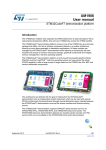
This tutorial shows how to read the contents of a text file from a USB memory stick attached to a development board. After
pressing an update button on the touch screen, the content is shown on the LCD. The tutorial explains the required steps to
create the application on a STM32F429I-Discovery board but can be easily ported to other underlying hardware as it is using
MDK-Professional Middleware and CMSIS, the Cortex Microcontroller Software Interface Standard.
A set of videos is available that shows the steps to create this project. Please visit www.keil.com/mdk5/learn/usb_host
Contents
Abstract ...................................................................................................................................................................................... 1
Introduction ............................................................................................................................................................................... 2
Software Stack ................................................................................................................................................................... 3
Prerequisites ............................................................................................................................................................................... 4
Set up the Workshop Environment .......................................................................................................................................... 4
Step 1: Create a Project............................................................................................................................................................. 5
Create a New Project for the Evaluation Board ....................................................................................................................... 5
Setup the Debug Adapter ......................................................................................................................................................... 6
Step 2: Add CMSIS-RTOS ....................................................................................................................................................... 7
Add and configure CMSIS-RTOS RTX for a simple Blinky application ................................................................................ 7
RTX Kernel Awareness ........................................................................................................................................................... 9
Step 3: Add USB Host with Mass Storage Support .............................................................................................................. 10
Configure the CMSIS-Driver for USB component ................................................................................................................ 10
Add the USB Host middleware component to the project ..................................................................................................... 11
Configure the CMSIS-Driver for the USB Host .................................................................................................................... 11
Configure the stack and thread memory resources ................................................................................................................ 12
Add the user code that accesses the USB storage device ....................................................................................................... 13
Step 4: Add the Graphical User Interface ............................................................................................................................. 17
Understanding the Hardware ................................................................................................................................................. 17
Add the Graphic Core and Graphics Display Interface.......................................................................................................... 17
Add the code to output “Hello World” to the LCD display ................................................................................................... 19
Step 5: Design and Add the Graphics to be Displayed on the LCD .................................................................................... 20
Configure GUIBuilder and Use it to Create the Graphics ..................................................................................................... 20
Add LogViewerDLG.c to the Project and Run the GUI ........................................................................................................ 21
Step 6: Add the Touch Screen Interface ................................................................................................................................ 22
Serial Wire Viewer Summary ................................................................................................................................................. 23
Document Resources ............................................................................................................................................................... 24
Books ..................................................................................................................................................................................... 24
Application Notes .................................................................................................................................................................. 24
Useful ARM Websites ........................................................................................................................................................... 24
Keil Products and Contact Information ................................................................................................................................ 25
Creating a Middleware Application using CMSIS Components with MDK Version 5
Introduction
This workshop explains how to create a software framework for a sophisticated microcontroller application using CMSIS and
Middleware components. During this workshop a demo application is created that implements the following functions:
Read the content of "Test.txt" file from a USB memory stick.
Show this content on a graphical display.
Provide an update button on a touch screen.
Copyright © 2014 ARM Ltd. All rights reserved
Application Note: 268
2
www.keil.com
Creating a Middleware Application using CMSIS Components with MDK Version 5
Software Stack
The application is created by using user code templates. These templates are part of software components such as the
Middleware, CMSIS-RTOS or the STM32F4xx Device Family Pack (DFP). Some other source files are automatically
generated such as the code that is creating the graphical user interface (GUI) on the external display (LogViewerDLG.c).
CMSIS-RTOS RTX is a real-time operating system that is part of MDK and adheres to the CMSIS specification. It is used
to control the application.
The board support files enable the user to quickly develop code for the hardware that is used here. It provides a simple API
to control LEDs, the touch screen and the LCD interface. Other components provide support for push buttons, joysticks, A/D
converters or other external devices.
Middleware provides stacks for TCP/IP networking, USB communication, graphics, and file access. The Middleware used
in this application is part of MDK-Professional and uses several CMSIS-Driver components.
CMSIS-Driver is an API that defines generic peripheral driver interfaces for middleware making it reusable across
compliant devices. It connects microcontroller peripherals with middleware that implements for example communication
stacks, file systems, or graphic user interfaces. CMSIS-Driver are available for several microcontroller families and are part
of the DFPs. The DFP contains the support for the device in terms of startup and system code, a configuration file for the
CMSIS-Driver and a device family specific software framework with hardware abstraction layer (HAL).
The basis for the software framework is CMSIS-Core that implements the basic run-time system for a Cortex-M device and
gives the user access to the processor core and the device peripherals. The device header files adhere to the CMSIS-Core
standard and help the user to access the underlying hardware.
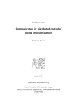
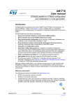
The STM32F32F429IDiscovery Kit with the USB Stick connected to USB User OTG Connector.
The LCD displays the screen as created in the Graphical Display section in Step 4, 5 and 6. In the example given in this
tutorial, the display will be rotated 90 º from that shown above.
Copyright © 2014 ARM Ltd. All rights reserved
Application Note: 268
3
www.keil.com
Creating a Middleware Application using CMSIS Components with MDK Version 5
Prerequisites
To run through the workshop you need to install the following software. Directions are given below:
MDK-ARM Version 5.14 or later (https://www.keil.com/demo/eval/arm.htm).
A valid MDK-Professional license.
Keil::MDK-Middleware 6.3.0 or higher, ARM::CMSIS 4.3.0 or higher, Keil::ARM_Compiler 1.0.0 or higher
Keil::STM32F4_DFP 2.4.0 or later which includes the STM32F429I-Discovery Board Support Package (BSP). We
will download this from the Internet using Pack Installer.
STM32F429I-Discovery Kit (www.st.com/web/catalog/tools/FM116/SC959/SS1532/PF259090).
Note: Solder bridge SB9 must be bridged in order for the Serial Wire Viewer (SWV) to work. A soldering iron is
needed. If you do not solder SB9, the examples will work but the Event Viewer, Trace Records and Exception
windows will not display any information as these require SWV for their operation. See page 24.
Text snippets for copy and paste and completed projects are here: www.keil.com/appnotes/docs/apnt_268.asp
This tutorial assumes you have some experience with the MDK development tool and a basic knowledge of C.
Set up the Workshop Environment
Install MDK:
1.
Install MDK-ARM Version 5.14 or later. Use the default folder C:\Keil_v5 for the purposes of this tutorial.
2.
After the initial MDK installation, the Pack Installer utility opens up. Read the Welcome message and close it.
Install the STM32F4xx Software Pack:
1.
If Pack Installer is not open, first open µVision®:
2.
The bottom right corner should display ONLINE:
3.
Locate Keil::STM32F4xx_DFP. Click Install:
The installation will commence.
4.
Once the Pack is installed this will be displayed indicating a successful installation:
. Then open Pack Installer by clicking on its icon:
If it displays OFFLINE, connect your PC to the Internet.
Install the other required Software Packs:
5. Locate Keil::MDK-Middleware. Click Update
2.
Locate ARM::CMSIS. Click Update
3.
Locate Keil::ARM_Compiler and click Install
Install your MDK-Professional license.
1.
In µVision, click on File License Management, select the 7 day license. This button is only displayed if you are
eligible for this offer. It can be used only
once.
2.
You may contact our sales team to request a time-limited license for this workshop: www.keil.com/contact
3.
For more information and license installation instructions see: www.keil.com/download/license/
Install the ST-Link V2 USB Drivers:
1.
Using Windows Explorer, navigate to C:\Keil_v5\ARM\STLink\USBDriver
2.
Double click on stlink_winusb_install.bat to install the required USB drivers for the on-board ST-Link V2 debug
adapter. The drivers will install in the usual fashion.
3.
Update the ST-Link firmware by executing C:\Keil_v5\ARM\STLink\ST-LinkUpgrade.exe. The best ST-Link V2
firmware to use is V2.J23.S0 or later. You can identify the version installed in your board with this Upgrade utility.
You need the Discovery board connected to your PC as described below to change its firmware.
Connect the STM32F419I-Discovery Board to your PC:
1.
Use the USB-Mini cable to connect your computer and the STM32F4-Discovery board using the port labeled as
“USB ST-LINK”.
Copyright © 2014 ARM Ltd. All rights reserved
Application Note: 268
4
www.keil.com
Creating a Middleware Application using CMSIS Components with MDK Version 5
Step 1: Create a Project
Create a New Project for the Evaluation Board
Create a project with initialization files and the main module:
1.
2.
3.
4.
5.
6.
7.
8.
In the main µVision menu, select Project New µVision Project. The Create New Project window opens up.
Create a suitable folder in the normal fashion and name your project. We will use C:\USB and the project name will
be USB. When you save the project the project file name will be USB.uvprojx.
The Select Device for Target window opens. Select STM32F429ZITx:
Click on OK and the Manage Run-Time Environment window opens:
Expand the various options as shown and select CMSIS:Core, Device:Startup. Most
devices provide additional hardware
abstraction layers that are listed under the
Device component. The STM32Cube
HAL is a list of available drivers for the
STM32F429. It requires a framework.
Select STM32Cube Framework
(API):Classic. For more information,
click on the link STM32Cube Framework
which opens the documentation (red
circle).
In the SEL. Column will be some orange
blocks. Click on Resolve and these will
turn to green.
Click OK to close this window
In the Project window expand all the items and have a look at the files
µVision has added to your project:
Add the main.c file:
1.
2.
3.
Right click on Source Group 1 and select Add New Item to Group
'Source Group 1'…
In the window that opens, select User Code Template. Select 'main'
module for STM32Cube. It initializes the STM32Cube HAL and
configures the clock system.
Click on Add.
Set the CPU Clock Speed:
The external crystal oscillator on the development kit has a frequency of 8 MHz.
1.
Select Target Options
or ALT-F7 and select the Target tab.
Enter 8 MHz in the Xtal (MHz) box.
2.
3.
4.
Select the C/C++ tab.
Enter HSE_VALUE=8000000 in the Define box. The HSE_VALUE represents the
crystal frequency. This will set the CPU clock to 168 MHz in system_stmf4xx.c.
Click on OK to close this window.
5.
Select File Save All or press
6.
Compile the project source files:
There will be no errors or warnings displayed in the Build Output window. If
you get any errors or warnings, please correct this before moving on to configure the ST-Link V2 Debug Adapter.
What we have at this point: We have created a new MDK 5 project called USB.uvprojx. We have set the CPU clock speed,
added the CMSIS environment, a main.c file and compiled the source files to test everything.
Copyright © 2014 ARM Ltd. All rights reserved
Application Note: 268
5
www.keil.com
Creating a Middleware Application using CMSIS Components with MDK Version 5
Setup the Debug Adapter
Select the ST-Link V2 debug adapter:
1.
2.
3.
4.
Select Target Options
or ALT-F7. Select the Debug tab.
In the Use box select “ST-Link Debugger”.
Click on Settings. In the Port box, select SW (for Serial-Wire Debug SWD).
In the SWDIO box you must see a valid IDCODE and ARM CoreSight
SW-DP. This indicates that µVision is connected to the STM32's debug
module.
If you see an error or nothing in the SWDIO box, you must fix this before you
can continue. Make sure the board is connected.
Configure the Serial Wire Viewer (SWV):
1.
Select the Trace tab. In the Core Clock box, enter 168 MHz and
select Trace Enable. This sets the speed of the SWV UART signal
and debugger timing displays. Unselect EXCTRC (Exception Tracing). Leave all other settings at their defaults.
Note: Solder Bridge SB9 must be bridged for SWV to function.
Select the Flash programming algorithm:
2.
3.
4.
Select the Flash Download tab.
Confirm STM32F4xx 2 MB Flash programming
algorithm is selected as shown here:
If not, click on Add to choose it.
Click on OK twice to return to the main menu.
5.
Compile the project source files:
6.
Program the Flash and start Debugging by clicking on its icon to enter µVision's Debug mode:
7.
Click on the RUN icon
8.
The program is now running now. Note: you may stop the program with the STOP icon
.
.
Insert a global variable in the Watch window:
1.
2.
3.
4.
In the Project tab under Device, double-click on system_stm32f4xx.c to open it up.
Find the variable SystemCoreClock. It is declared near line 138.
Right click on it and select Add SystemCoreClock to… and select Watch 1. Watch 1 will automatically open if it
is not already open and display this variable.
In the Watch 1 window, right click on SystemCoreClock in the Name column and unselect Hexadecimal Display.
SystemCoreClock will now be displayed with the correct
frequency of 168 MHz.
Note: You can add variables to the Watch and Memory windows
while your program is running.
5.
Stop the program.
The program counter (R15) will be at a B
instruction in the SysTick_Handler. The B instruction is a branch
to itself. Stopping in the SysTick Handler can be
avoided by adding the user code template
"Exception Handlers and Peripheral IRQ". As we
are going to use CMSIS-RTOS RTX, this is not
required here.
6.
The yellow arrow is the program Counter (PC).
7.
Exit Debug mode.
What we have at this point: We have selected the debug adapter, enabled the Serial Wire Viewer trace (SWV) and selected
the Flash programmer. We also demonstrated how to display the CPU clock in a Watch window.
Copyright © 2014 ARM Ltd. All rights reserved
Application Note: 268
6
www.keil.com
Creating a Middleware Application using CMSIS Components with MDK Version 5
Step 2: Add CMSIS-RTOS
Add and configure CMSIS-RTOS RTX for a simple Blinky application
Select and Configure RTX RTOS:
1.
2.
3.
4.
5.
6.
7.
Open the Manage Run-Time Environment window:
Under CMSIS:RTOS (API) select Keil RTX as shown here:
Click OK to close this window.
In the Project Window, note two new files are added under
CMSIS heading: RTX_CM4.lib and RTX_Conf_CM.c
Double click on RTX_Conf_CM.c to open it.
Click on the Configuration Wizard tab at the bottom.
Expand RTX Kernel Timer Tick Configuration and change RTOS
Kernel Timer input clock frequency [Hz] to 168000000 (168 MHz).
Add the Timer.c source file and add Timer Initialization Function Call:
1.
2.
3.
4.
5.
6.
In the Project window under Target 1, right click Source Group 1 and select Add New Item Group 'Source
Group 1'…
In the window that opens, select User Code Template. Select CMSIS-RTOS Timer.
Click on Add. Note Timer.c is added to the Source Group 1 in the Project window.
Click on the main.c tab to bring it in focus in order to edit it.
In main.c near line 76, add this line: extern void Init_Timers(void);
In main.c near line 103 just after SystemClock_Config();, add Init_Timers();
Init_Timers creates two timers: Timer1 (a one-shot) and Timer2 which is a 1 second periodic timer. Timer2 calls a
callback function.
7.
Select File Save All or
8.
Compile the project source files by clicking on the Rebuild icon
. There will be no errors or warnings in the
Build Output window. If there are any errors or warnings, please correct them before continuing.
.
Demonstrating the Timer is Working:
1.
Program the Flash and enter Debug mode:
Click on the RUN icon.
TIP: To program the Flash manually, select the Load icon:
2.
3.
4.
The program is running.
In Timer.c, near line 32, set a breakpoint by
clicking on the gray box. A red circle will appear.
The gray box indicates that assembly language
instructions are present and a hardware breakpoint
will be legal.
The program will soon stop here.
5.
6.
Click on RUN
and in 1 second it will stop here again when the Timer2 is activated.
Remove the breakpoint for the next step.
What we have at this point: We added the RTX RTOS to your project. We enabled a periodic Timer and demonstrated that
the program is running.
Copyright © 2014 ARM Ltd. All rights reserved
Application Note: 268
7
www.keil.com
Creating a Middleware Application using CMSIS Components with MDK Version 5
Blink the LED:
1.
Exit Debug mode.
2.
3.
Open the Manage Run-Time Environment window:
Expand the Board Support (ensure that STM32F429IDiscovery is selected – see the red arrow)
Under Board Support:LED (API) select LED
Click OK to close this window.
4.
5.
In the Project window, a header called Board Support is created
containing a file LED_F429Discovery.c. This configures the I/O
pins used by the LEDs with an LED_Initialize routine. The LED_On and LED_Off functions are used to control the
LEDs.
Add C Code to Blink LED LD3:
In main.c, near line 45, add #include "Board_LED.h"
Note: An error
might display on this line. Please ignore this for now. Make sure the source lines are typed in exactly as
shown to avoid errors. Use your best judgment as to where the source code should be added. Line numbers can change with
different versions of the software templates.
TIP: You can also select #includes from a list:
Select a line in a source code file and right click on it.
Select Insert '#include file'. A menu opens up with provided #includes that you can select from.
1.
2.
3.
In main.c, near line 104, add LED_Initialize();
Just after Init_Timers(); is a good place
In Timer.c, near line 3, add these two lines:
#include "Board_LED.h"
static int timer_cnt = 0;
In Timer.c inside the Timer2_Callback function near line 32, add this code in the user code section (replace the line
//add user code here):
timer_cnt++;
if (timer_cnt & 1) LED_On (0);
else
LED_Off(0);
4.
Select File/Save All or
.
5.
Compile the project:
There will be no errors or warnings in the Build Output window.
6.
Program the Flash and enter Debug mode:
7.
8.
9.
Click on RUN.
LED PG13 (green) will now blink according to the Timer you have created.
Leave the program running for the next steps.
TIP: In the LED_On function call: (0) is the green LED. Using (1) will blink the red LED.
What we have at this point: We have selected a LED driver from the CMSIS-Pack BSP to create a blinking a LED. We
have created a simple program that blinks this LED every 1 second using a timer.
Copyright © 2014 ARM Ltd. All rights reserved
Application Note: 268
8
www.keil.com
Creating a Middleware Application using CMSIS Components with MDK Version 5
RTX Kernel Awareness
System and Thread Viewer:
1.
2.
3.
4.
5.
6.
With the program
running, open Debug
OS Support and select
System and Thread
Viewer. This window
opens up:
Note: os_idle_demon
and osTimerThread
threads have been
already created.
Set a hardware
breakpoint in the
Timer.c function
Timer2_Callback as you did previously near lines 31 through 35.
When you click on RUN, the status of these two threads will be updated in real-time until the program stops.
Note the various other fields that describe RTX.
This is a very simple RTX implementation. We will add more threads. These threads will be automatically added to
this window as you create them. This window needs no configuration or stubs in your source code.
Remove the breakpoint.
Event Viewer:
1. Open Debug OS Support and select
Event Viewer. The following window
opens. Resize it for convenience. If this
window does not display any information,
the most likely cause is that the SWV is
not enabled or the CPU clock frequency is
incorrect. See Serial Wire Viewer
Summary on the last page for useful
SWV hints.
2.
3.
Click on RUN.
Using In, Out and All in the Zoom field,
set the grid for about 0.5 seconds.
4. It is easy to see when the threads are
running. Note most of the time the Idle
thread is running.
5. You can tell at a glance the timing of your RTX implementation and if it is behaving as you expect.
6. As you add new tasks, they will be automatically added. The Event Viewer uses the Serial Wire Viewer (SWV).
7. Click on Stop in Update Screen.
8. Enable Task Info and Cursor.
9. Click on one of the osTimerThread(1) events. A red line will appear.
10. Position your mouse over the next Timer Thread event. Keep your cursor in the osTimerThread row for correct
sampling.
11. The following window will open. Note the time (Delta) between the threads is about 1.006 second. This is close to
the rate of the blinking LED.
There is a minor sampling
error present.
12. Stop the processor
.
13. Exit Debug mode.
Copyright © 2014 ARM Ltd. All rights reserved
Application Note: 268
9
www.keil.com
Creating a Middleware Application using CMSIS Components with MDK Version 5
Step 3: Add USB Host with Mass Storage Support
Configure the CMSIS-Driver for USB component
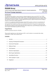
To correctly configure the USB Host middleware it is necessary to understand the USB User connector available on the
target hardware.
The STM32F429I Discovery Kit provides a USB connector that interfaces with the USB OTG High-speed STM32F429
peripheral via the on-chip full-speed PHY (GPIOB.14 and GPIOB.15). The VBUS power on/off pin is active low on
GPIOC.4. The overcurrent detection pin is active low on GPIOC.5. Since
we are only using the USB Host interface we can ignore the remaining OTG
pins.
This schematic is part of the Software Pack for the STM32F4. You access
these documents using the Books tab. Other documents found here are
datasheets, STMicroelectronics Getting Started Guides, ARM compiler and
µVision manuals and more. The Books tab is located with the Project and
Functions tabs:
Copyright © 2014 ARM Ltd. All rights reserved
Application Note: 268
10
www.keil.com
Creating a Middleware Application using CMSIS Components with MDK Version 5
Add the USB Host middleware component to the project
As we want to connect a USB memory stick to the development board, we need to add support for the USB Mass Storage
Class (MSC) to the project:
1.
2.
3.
4.
5.
Open the Manage Run-Time Environment window:
Under USB:Host, select MSC as shown here:
Make sure you do not accidentally select MSC in the Device header.
We are setting the STM32 up as a Host and not a Device.
Under CMSIS Driver:USB Host (API), select High-speed
Click Resolve to add other mandatory middleware components.
Click OK to close this window.
Connect USB Host 0 to the Hardware and increase stack size:
1.
2.
3.
4.
5.
6.
In the Project window under the USB heading, double click on
USBH_Config_0.c (Host) to open it.
Click on its Configuration Wizard tab and then on Expand All.
Set Connect to hardware via Driver_USBH# to 1. Note: The
USB OTG High-speed interface is represented by Driver_USBH1
This is the CMSIS-Driver that configured in the previous step.
Change the Core Thread Stack Size at the bottom of the
configuration file to 540. Using the default value, the program
will stop with a stack overflow.
Select File/Save All or
.
Configure the CMSIS-Driver for the USB Host
1.
In the Project window, under the Device header, double
click on RTE_Device.h to open it for editing.
2.
Click on its Configuration Wizard tab.
3.
Enable USB OTG High-speed as shown here:
4.
Set the hardware parameters for the USB OTG Highspeed interface exactly as shown here:
Both Ports must be GPIOC and first Bit is 4 and
the second is 5.
Change the PHY Interface to On-chip Fullspeed PHY.
Next we will configure the stack, heap and thread resources for the
middleware components we have just added.
Copyright © 2014 ARM Ltd. All rights reserved
Application Note: 268
11
www.keil.com
Creating a Middleware Application using CMSIS Components with MDK Version 5
Configure the stack and thread memory resources
The resource requirements of the USB component can be found in the Middleware documentation that is accessible using the
link next to the USB component in the Manage RunTime Environment window:
Configure Heap and Thread Stack USB sizes:
1.
2.
3.
4.
5.
6.
In the Project window under the Device heading, double click on startup_stm32f429xx.s to open it.
Select its Configuration Wizard tab. Confirm the Stack Size is set to 0x400 bytes and Heap Size is set to 0x200.
Under the CMSIS heading, double click on RTX_Conf_CM.c to open it.
Change Default Thread stack size [bytes] to 1000.
Set Number of threads with user-provided stack size to 1.
Set Total stack size [bytes] for threads
with user-provided stack size to 1000
as shown here:
Set the Default Drive Letter:
1.
2.
3.
In the Project window under the File System heading, double click on FS_Config.c to open it.
Select the Configuration Wizard tab.
For a USB mass storage drive, the File System
component expects the drive letter to be U0. So
change Initial Current Drive to U0:
4.
Select File/Save All or
5.
Compile the project:
.
No errors or warnings will be generated as shown in the Build Output window. Please correct any errors or warnings before
you continue.
Next we will add the user code to access a USB Device (the USB stick)
Copyright © 2014 ARM Ltd. All rights reserved
Application Note: 268
12
www.keil.com
Creating a Middleware Application using CMSIS Components with MDK Version 5
Add the user code that accesses the USB storage device
We will use a CMSIS-RTOS Thread to implement access to a file on the USB stick.
Add Thread.c:
1.
2.
3.
4.
Right click on Source Group 1 in the Project window. Select Add New item to Group 'Source Group1'…
Select User Code Template.
Under the CMSIS heading and in the Name column, select CMSIS-RTOS Thread.
Click on Add. This adds the file Thread.c to your project.
Add USBH_MSC.c and USBH_MSC.h:
1.
2.
3.
4.
5.
Right click on Source Group 1 in the Project window again. Select Add New item to Group 'Source Group1'…
Select User Code Template.
Under the USB heading and in the Name column, select USB Host Mass Storage Access and click on Add.
The files USBH_MSC.c and USBH_MSC.h are now added to your project under the Source Group 1 heading.
These provide the relevant access functions for the USB storage device.
6.
Select File/Save All or
Modify Thread.c:
To allow file access we add the following application code in the module Thread.c:
1.
Double click on Thread.c to open it for editing.
2.
Note near lines 17 and 18 there are two C lines: return(0); and }
3.
Delete everything after these two lines but not including them. Start deleting with the void Thread (line 20).
Append this code to Thread.c:
#include "USBH_MSC.h"
char fbuf[200] = { 0 };
void Thread (void const *argument) {
static unsigned int result;
static FILE *f;
USBH_Initialize (0);
while (1) {
result = USBH_MSC_DriveMount ("U0:");
if (result == USBH_MSC_OK) {
f = fopen ("Test.txt", "r");
if (f) {
fread (fbuf, sizeof (fbuf), 1, f);
fclose (f);
}
}
osDelay (1000);
}
4.
}
Make sure you have at least one newline (CR) at the end of the text. Otherwise, this will generate an easily fixed
warning at compilation time.
To start this new RTX Thread:
1.
2.
In main.c near line 77, add after extern void Init_Timers: extern void Init_Thread(void);
In main.c near line 112, add before osKernelStart ();: Init_Thread();
3.
Select File/Save All.
What we have at this point: On this page we added the code to open, read and close the data in file Test.txt located in a
USB stick connected to USB User.
Copyright © 2014 ARM Ltd. All rights reserved
Application Note: 268
13
www.keil.com
Creating a Middleware Application using CMSIS Components with MDK Version 5
Prepare a USB memory stick:
1.
2.
3.
Take a USB memory stick and create a file called Test.txt containing a short message using ASCII characters.
We will use the message Keil Middleware and CMSIS-Pack.
Plug this stick with an adapter cable to the STM32F429I-Dicovery board's USB connector labelled USB USER.
Build and RUN:
1.
Compile the project:
2.
3.
4.
Enter Debug mode:
Click on the Memory 1 tab. Enter fbuf in this window:
Right click anywhere in the data field area and select
Ascii
Set a breakpoint in Thread.c on fclose (f) near
line 35.
5.
6.
. You might get a warning from the USBH_MSC.c that can be safely ignored.
7.
Click on RUN.
In a few seconds the text will
appear in the Memory 1 window.
The program will stop on the hardware breakpoint.
8.
To repeat this sequence, click on the RESET icon
and then RUN
.
System and Thread Viewer:
1.
Select the System and Thread
Viewer tab or select Debug
OS Support System and
Thread Viewer if it is not open.
Note the thread Thread is
running and the os_idle_demon
is Ready to run next. The other
other two threads are in wait
states.
2.
Click on the RESET icon
3.
and then RUN
. You will see
the idle demon run as the
program runs and Thread go into
the running state when the breakpoint is hit.
Remove the breakpoint in Thread.c on the line fclose (f).
4.
5.
Click on RUN.
Leave the program running for the next steps.
Copyright © 2014 ARM Ltd. All rights reserved
Application Note: 268
14
www.keil.com
Creating a Middleware Application using CMSIS Components with MDK Version 5
Viewing RTX Activity with the Event Viewer:
Note: If this window is blank, the Serial Wire Viewer must be configured and SB9 bridged.
1.
2.
3.
Select the Event Viewer tab or if not already open: Select Debug OS Support Event Viewer.
Adjust the column width so the entire Thread names are visible as shown below. Data will be visible if the Serial
Wire Viewer (SWV) is configured properly.
Set the grid to 2 ms using Zoom In and Out. Scroll to the end of the Event Viewer as shown below.
Note the Threads visible: The Thread (3) data shows the activity of this thread before the breakpoint. Observer that most of
the procesor time was spent in the Idle daemon. You can adjust these times to sut your application.
More Viewing RTX Activity with the Event Viewer:
1.
2.
3.
4.
Select Stop in the Update Screen box.
Set the grid to 10 ms.
Scroll backwards in time and you can see when the other threads were active.
Recall you can enable the Cursor and Task Info boxes to measure timings of these events.
Modifying the Memory 1 Window:
1.
In the Memory 1 window displaying the text, right-click on one of the characters and select Modify Memory
@address.
2.
Enter a 0 and press Enter.
3.
The character you selected will be changed to 0 and then back to the original as Text.txt is read again by the thread
Thread.
4.
The Memory 1 window updates in real-time and can be changed while the program is running.
Copyright © 2014 ARM Ltd. All rights reserved
Application Note: 268
15
www.keil.com
Creating a Middleware Application using CMSIS Components with MDK Version 5
Exception Trace window:
1.
2.
3.
4.
Open the Trace Exception window: click on the down arrow beside the Trace icon:
Select Trace Exceptions. Trace Exceptions window opens up with its own tab.
Enable EXCTRC: Exception Tracing as shown in the window below:
Click on the Count column header until the down triangle appears. The active exceptions will
be displayed with various statistics as shown below. Note: this window is updated while the program is running.
Trace Records window:
1.
2.
3.
4.
5.
6.
7.
8.
9.
Open the Trace Records window: click on the down arrow beside the Trace icon:
Double click inside it to clear the window.
The exceptions will be listed as they occurred as shown below.
Right click in this window and you can filter out different types of events.
An "x" in the Ovf column means there was a frame lost. This is because there was too much data output on the 1 bit
Serial Wire Output (SWO) pin. You can alleviate this by unselecting the Timestamps and ITM bit 31. The overflows
might disappear but the Event Viewer will not function without these two attributes set.
An "x" in the Dly column means the Timestamp might not be accurate at this point. µVision recovers gracefully
from such SWV trace data overflows.
You can also alleviate overflows by using a Keil ULINKpro debug adapter. ULINKpro can use the 4-bit ETM trace
which provides more bandwidth. A board must be equipped with the CoreSight 20 pin ETM connector (not
available on the STM32F429i-Discovery board).
Close the Trace Records window.
Disable EXCTRC: Exception Tracing in the Trace Exceptions window.
10. Stop the processor
.
11. Close the two Trace windows.
12. Exit Debug mode.
Copyright © 2014 ARM Ltd. All rights reserved
Application Note: 268
16
www.keil.com
Creating a Middleware Application using CMSIS Components with MDK Version 5
Step 4: Add the Graphical User Interface
Understanding the Hardware
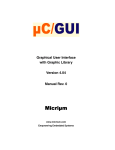
To correctly configure the Graphic Interface it is necessary to understand the schematics. Here’s another excerpt from the
schematics showing the LCD connections.
The STM32F429 has a high-speed RGB interface (red) that is connected to the LCD. To configure the display, SPI (blue) is
used which is connected to the device’s SPI5 interface. The Touch Screen connects via I2C (green) to the microcontroller’s
I2C3 interface.
Interfaces:
RGB
SPI
I2C
Add the Graphic Core and Graphics Display Interface
Select the emWin Graphics components:
1.
2.
3.
4.
5.
6.
Open the Manage Run-Time Environment window:
Under Board Support:emWin LCD (API), select emWin LCD. This
component is the interface to the board LCD display.
Select Graphics:Core. This will be used for the User interface.
Graphics:Core needs a display interface configuration file where screen
size and other parameters are defined. Pre-defined displays are available
under Graphics Display. Select STM43F429I-Discovery.
Click Resolve to add the missing CMSIS-Drivers.
Click OK to close this window.
Copyright © 2014 ARM Ltd. All rights reserved
Application Note: 268
17
www.keil.com
Creating a Middleware Application using CMSIS Components with MDK Version 5
Modify System Clock and set Defines:
The microcontroller connects the graphics display as an external SDRAM. This SDRAM is usually configured with the
CMSIS system file (system_stm32f4xx.c). The STM32Cube Framework provides #defines to enable the SDRAM.
1.
2.
3.
4.
Select Target Options
or ALT-F7.
Select the C/C++ tab. Add the defines DATA_IN_ExtSDRAM and STM32F429I_DISCOVERY
Add a space between the three defines as shown here:
Click OK to close this window.
5.
Select File/Save All or
.
Configure the CMSIS-Driver SPI5 for Graphics:
1.
2.
3.
In the Project window under the Device heading, double click on RTE_Device.h to open it.
Select its Configuration Wizard tab.
Enable SPI5 and disable SPI_NSS pin. Set the
other options as shown here:
Configure Memory for Graphics Core
The Graphics Core uses a dedicated memory for its features that needs configuration.
1.
2.
In the Project window under the Graphics heading, double click on GUIConf.c to open it. GUIConf.c configures
the Graphics Core. The default configuration exceeds the memory of our system. We change the memory size to
0x4000 which is sufficient for many applications (refer to the emWin User Manual).
Change the GUI_NUMBYTES define near line 45 to 0x4000
3.
Select File/Save All or
.
What we have at this point: The graphics hardware configuration is complete.
Copyright © 2014 ARM Ltd. All rights reserved
Application Note: 268
18
www.keil.com
Creating a Middleware Application using CMSIS Components with MDK Version 5
Add the code to output “Hello World” to the LCD display
Add The Graphics Thread and start the thread in main.c:
1.
2.
3.
4.
In the Project window under Target 1, right click Source Group 1 and select Add New Item to Group ‘Source
Group 1'...
Select User Code Template.
From the Graphics heading, select emWin GUI Thread for Single-Tasking Execution Model.
Note: Single-task execution is where one thread (task) calls the emWin functions. This reduces the memory
footprint and is sufficient for many applications. Only one thread can call the GUI functions (refer to the Execution
Model in the emWin User Manual).
Click on Add. This adds the file GUI_Single_Thread.c to your project.
Modify RTX for this new Thread:
The GUI Thread needs a user provided stack size of 2048 bytes:
1.
2.
3.
4.
Under the CMSIS heading, double click on
RTX_Conf_CM.c to open it.
Select its Configuration Wizard tab and expand
Thread Configuration.
Increase Number of threads with user-provided
stack size to 2 as shown here:
Set Total stack size [bytes] for threads with user
provided stack size to 4096 as shown here:
Add the text that will display on the LCD:
1.
2.
In the Project window under the Source Group 1 heading, double click on GUI_SingleThread.c to open it.
Near line 24, just before the while(1) loop, add: GUI_DispString("Hello World!");
3.
Select File/Save All or
.
Modify main.c:
You can now demonstrate the display of the string “Hello World!” on the LCD:
1.
2.
In main.c near line 79 add: extern int Init_GUIThread (void);
In main.c near line 109 add: Init_GUIThread();
3.
Select File/Save All or
.
Build and run your project:
1.
Compile the project:
2.
Program the Flash and enter Debug mode:
3.
4.
Click on RUN.
The LCD will display Hello World!
5.
Stop the processor
. Exit Debug mode.
Copyright © 2014 ARM Ltd. All rights reserved
Application Note: 268
19
www.keil.com
Creating a Middleware Application using CMSIS Components with MDK Version 5
Step 5: Design and Add the Graphics to be Displayed on the LCD
Configure GUIBuilder and Use it to Create the Graphics
emWin provides a tool called GUIBuilder to design the graphics that will display on the LCD screen. µVision allows you to
execute GUIBuilder from within.
1.
2.
3.
Open the Manage Run-Time Environment window:
Under Graphics:Tools select GUI Builder
Click OK
Create a shortcut on the µVision Tools menu:
1.
2.
3.
4.
In the main µVision menu, select Tools
Customize Tools Menu. The window below opens
up.
This will allow you to add a shortcut to your tools
menu to launch GUIBuilder. This only needs to be
done once for every installation of MDK-ARM and
not every project that you may create.
6.
Click on the Insert icon
(or press the Insert key).
Enter the text GUIBuilder as shown and press
Enter.
In the Command and Initial Folder boxes enter
.\RTE\Graphics\GUIBuilder.exe and .\ .
Click on OK to close it.
7.
8.
Click on Tools in µVision and the new GUIBuilder menu item will display like this:
Click on GUIBuilder and it will start.
5.
Create the Frame:
1.
2.
3.
4.
Click on the Framewin icon:
A box will be created labelled Framewin.
With the FrameWin box selected, change the Property Name from FrameWin to
LogViewer.
In the property column, enter xSize = 240 and ySize = 320. This specifies the size
of the LCD.
Press Enter.
Add the Multi Edit Widget
1.
2.
Click on the Multiedit
icon:
Click and drag to fill the LogViewer area as shown below. Leave a space at the bottom for the button.
Add the Button:
1.
2.
3.
4.
Click on the Button icon:
Using your mouse to size and position as shown below:
With the Button selected, change the Property Name to Update.
Click Enter to finish.
Copyright © 2014 ARM Ltd. All rights reserved
Application Note: 268
20
www.keil.com
Creating a Middleware Application using CMSIS Components with MDK Version 5
Save and Export your GUI:
1.
2.
3.
Select File Save. A C source file with
your GUI design is created and saved into
your µVision project root folder. The file
name is derived from your parent GUI
element, and in this case the name is
LogViewerDLG.c.
You will need to add this to your project.
This step is done on the next page.
Close GUIBuilder.
Add LogViewerDLG.c to the Project and Run the GUI
Adding your GUI design file LogViewerDLG.c to Your Project:
1.
2.
3.
4.
5.
6.
In the µVision Project window, right click on “Source Group 1”.
Select Add Existing Files to Group 'Source Group 1'…
Note: Choose Existing rather than New as previously.
In the window that opens up, select the file LogViewerDLG.c. Click on Add once and then Close.
LogViewerDLG.c is now added to your project.
In the Project window, under Source Group 1, double click on LogViewerDLG.c to open it for editing.
Near line 70, add this line to reference the file buffer fbuf: extern char fbuf[200];
This should in between the //User Start near line 69 and //User END near line 70.
Create the GUI Design:
1.
2.
3.
4.
5.
In the µVision Project window under Source Group 1, double click on GUI_SingleThread.c to edit it.
In GUI_SingleThread.c, near line 4 add this line: #include "dialog.h"
In GUI_SingleThread.c, near line 5 add this line: extern WM_HWIN CreateLogViewer(void);
Comment out: //GUI_DispString("Hello World!");
Near line 26 add this line: CreateLogViewer();
Build and RUN:
1.
Select File/Save All or
.
2.
Compile the project:
3.
4.
Enter Debug mode:
and click on RUN.
The GUI we have just created, appears on the screen:
Copyright © 2014 ARM Ltd. All rights reserved
Application Note: 268
21
www.keil.com
Creating a Middleware Application using CMSIS Components with MDK Version 5
Step 6: Add the Touch Screen Interface
An implementation for the touch screen interface is provided as a Software Component under Board Support. The touch
screen hardware connects via the I2C peripheral (I2C3) and therefore we will use the standard CMSIS-Driver for I2C.
Add Software Components for Touchscreen
1.
2.
3.
4.
Open the Manage Run-Time Environment window:
Under Graphics:Input Device, select Touchscreen
Click Resolve to select other required components. This adds from the Board Support the Touchscreen Interface and
from the CMSIS Driver the I2C driver.
Clock OK to close this window.
Configure the CMSIS-Driver for the I2C Interface
1.
2.
3.
4.
In the Project window, under the Device group, double
click on RTE_Device.h to open it for editing.
Click on its Configuration Wizard tab.
Enable I2C3 and configure the parameters for this driver
instance as shown in the picture. Select PA8 and PC9
since these pins provide the interface to the touchscreen
hardware.
Touchscreen is a low-bandwidth interface and therefore we
can disable the DMA channels. This avoids DMA conflicts
with other drivers.
Enable Touch support in GUI_SingleThread.c
1.
In the Project window, under Source Group 1, double click on LogViewerDLG.c to open it for editing.
2.
Near line 118 is case WM_NOTIFICATION_CLICKED for the Update button, add this code:
hItem = WM_GetDialogItem(pMsg->hWin, ID_MULTIEDIT_0);
MULTIEDIT_SetText(hItem, fbuf);
3.
4.
In the Project window, under Source Group 1, double click on GUI_SingleThread.c to open it for editing.
Uncomment line 33 to call the touch support of the Graphics component: GUI_TOUCH_Exec();
Build and RUN:
5.
Select File/Save All or
.
6.
Compile the project:
7.
8.
Enter Debug mode:
and click on RUN.
Press the Update button on the LCD. The content of the file Test.txt appears on the screen:
Copyright © 2014 ARM Ltd. All rights reserved
Application Note: 268
22
www.keil.com
Creating a Middleware Application using CMSIS Components with MDK Version 5
Serial Wire Viewer Summary
Serial Wire Viewer (SWV) is a 1 bit data trace. It is output on the SWO pin which is shared with the JTAG TDO pin. This
means you cannot use JTAG and SWV together. Instead, use Serial Wire Debug (SWD or SW) which is a two pin alternative
to JTAG and has about the same capabilities. SWD is selected inside the µVision IDE amd is easy to use.
1.
2.
3.
4.
5.
6.
7.
The STM329F429I Disco board must have the Solder Bridge SB9 bridged. SB9 is located on the bottom of the
board close to jumper ldd. If SB9 is open, SWV will not work. The board is shipped with SB9 not bridged.
The Core Clock: is the CPU frequency and must be set accurately. In this tutorial, 168 MHz is used. If you see ITM
frames in the Trace Records window of number other than 0 or 31, or no frames at all, the clock frequency is
probably wrong.
SWV is configured in the Cortex-M Target Setup in the Trace tab. In Edit mode: Select Target Options
or
ALT-F7 and select the Debug tab. Select Settings: Then select the Trace tab. In Debug mode: Select Debug/Debug
Settings.. and then select the Trace tab.
Many STM32 processors need a special initialization file to get SWV and/or ETM trace to function. This file is not
needed in this board as µVision accomplishes this during entry to Debug mode. If you are using a different STM32
processor and are unable to get SWV working, contact Keil tech support. SWOxx.ini files are provided in many
µVision example projects that you can use. Insert it just below where you choose the debug adapter.
If SWV stops working, you can get it working by exiting and re-entering Debug mode. In rare cases, you might also
have to cycle the board power. Constant improvements to the ST-Link V2 firmware are helping in this regard.
SWV outputs its data over a 1 bit SWO pin. Overloading can be common depending on how much information you
have selected to be displayed. Reduce the information to only that which you really need helps as does limiting the
activity of variables. Using a ULINKpro on boards equipped with a 20 CoreSight ETM connector enables the SWV
information to be output on the 4 bit ETM trace port.
For more information on STM32F429I-Discovery board see: www.keil.com/appnotes/docs/apnt_253.asp
Watch, Memory windows and Serial Wire Viewer can display:
Global and Static variables. Raw addresses: i.e. *((unsigned long *)0x20000004)
Structures.
Peripheral registers – just read or write to them.
Can’t see local variables. (just make them global or static).
Cannot see DMA transfers – DMA bypasses CPU and CoreSight and CPU by definition.
You might have to fully qualify your variables or copy them from the Symbol window.
Serial Wire Viewer (SWV) displays in various ways:
PC Samples.
A printf facility that does not use a UART.
Data reads. Graphical format display in the Logic Analyzer: Up to 4 variables can be graphed.
Exception and interrupt events.
All these are Timestamped.
CPU counters.
Instruction Trace (ETM):
ETM Trace records where the program has been. Assembly instructions are all recorded.
Assembly is linked to C source when available (this is up to your program).
A recorded history of the program execution in the order it happened.
Provides Performance Analysis and Code Coverage. Higher SWV performance.
ETM needs a Keil ULINKpro to provide the connection to the 4 bit Trace Port found on many STM32 processors.
Copyright © 2014 ARM Ltd. All rights reserved
Application Note: 268
23
www.keil.com
Creating a Middleware Application using CMSIS Components with MDK Version 5
Document Resources
Books
NEW! Getting Started MDK 5: www.keil.com/mdk5/.
A good list of books on ARM processors is found at: www.arm.com/support/resources/arm-books/index.php
µVision contains a window titled Books. Many documents including data sheets are located there.
A list of resources is located at: www.arm.com/products/processors/cortex-m/index.php (Resources tab).
The Definitive Guide to the ARM Cortex-M0/M0+ by Joseph Yiu. Search the web for retailers.
The Definitive Guide to the ARM Cortex-M3/M4 by Joseph Yiu. Search the web for retailers.
Embedded Systems: Introduction to Arm Cortex-M Microcontrollers (3 volumes) by Jonathan Valvano.
MOOC: Massive Open Online Class: University of Texas:
http://users.ece.utexas.edu/~valvano/
Application Notes
1.
Overview of application notes:
www.keil.com/appnotes
2.
NEW! Keil MDK for Functional Safety Applications:
www.keil.com/safety
3.
Using DAVE with µVision:
www.keil.com/appnotes/files/apnt_258.pdf
1.
Using Cortex-M3 and Cortex-M4 Fault Exceptions
www.keil.com/appnotes/files/apnt209.pdf
2.
CAN Primer using NXP LPC1700:
www.keil.com/appnotes/files/apnt_247.pdf
3.
CAN Primer using the STM32F Discovery Kit
www.keil.com/appnotes/docs/apnt_236.asp
4.
Segger emWin GUIBuilder with µVision™
www.keil.com/appnotes/files/apnt_234.pdf
5.
Porting an mbed project to Keil MDK™
www.keil.com/appnotes/docs/apnt_207.asp
6.
MDK-ARM™ Compiler Optimizations
www.keil.com/appnotes/docs/apnt_202.asp
7.
Using µVision with CodeSourcery GNU
www.keil.com/appnotes/docs/apnt_199.asp
8.
RTX CMSIS-RTOS in MDK 5
http://www.keil.com/pack/doc/cmsis_rtx/index.html
9.
Lazy Stacking on the Cortex-M4
www.arm.com and search for DAI0298A
10. Sending ITM printf to external Windows applications:
11. Barrier Instructions
12. Cortex Debug Connectors:
www.keil.com/appnotes/docs/apnt_240.asp
http://infocenter.arm.com/help/topic/com.arm.doc.dai0321a/index.html
http://www.keil.com/support/man/docs/ulinkpro/ulinkpro_cs_connectors.htm
Useful ARM Websites
1.
2.
3.
4.
5.
6.
ARM Community Forums: www.keil.com/forum and http://community.arm.com/groups/tools/content
ARM University Program: www.arm.com/university. Email: [email protected]
ARM Accredited Engineer Program: www.arm.com/aae
mbed™: http://mbed.org
CMSIS standard: www.arm.com/cmsis
CMSIS documentation: www.keil.com/cmsis
For comments or corrections on this document please email [email protected].
Copyright © 2014 ARM Ltd. All rights reserved
Application Note: 268
24
www.keil.com
Creating a Middleware Application using CMSIS Components with MDK Version 5
Keil Products and Contact Information
Keil Microcontroller Development Kit (MDK-ARM™)
MDK-Lite (Evaluation version) - $0
MDK-ARM-CM™ (for Cortex-M series processors only – unlimited code limit)
MDK-Standard (unlimited compile and debug code and data size Cortex-M, ARM7 and ARM9)
MDK-Professional (Includes Flash File, TCP/IP, CAN and USB driver libraries and Graphic User Interface (GUI)
NEW! ARM Compiler Qualification Kit: for Safety Certification Applications
USB-JTAG adapter (for Flash programming too)
ULINK2 - (ULINK2 and ME - SWV only – no ETM)
ULINK-ME – sold only with a board by Keil or OEM.
ULINKpro – Faster operation and Flash programming, Cortex-Mx SWV & ETM trace.
NEW! ULINKpro D – Faster operation and Flash programming, Cortex-Mx SWV, no ETM trace.
For special promotional or quantity pricing and offers, please contact Keil Sales.
Contact [email protected]
800-348-8051 for USA prices.
Contact [email protected]
+49 89/456040-20 for pricing in other countries.
CMSIS-RTOS RTX is now provided under a BSD license. This makes it free.
All versions, including MDK-Lite, include CMSIS-RTOS RTX with source
code!
Keil includes free DSP libraries for the Cortex-M0, M0+, M3, M4 and M7.
Call Keil Sales for details on current pricing, specials and quantity discounts.
Sales can also provide advice about the various tools options available to you.
They will help you find various labs and appnotes that are useful.
All products are available from stock.
All products include Technical Support for 1 year. This is easily renewed.
Call Keil Sales for special university pricing. Go to www.arm.com/university
to view various programs and resources.
Keil supports many other Infineon processors including 8051 and C166 series
processors. See the Keil Device Database® on www.keil.com/dd for the complete list of Infineon support. This information is
also included in MDK.
For more information:
Keil Sales In USA: [email protected] or 800-348-8051. Outside the US: [email protected] or +49 89/456040-20
Keil Technical Support in USA: [email protected] or 800-348-8051. Outside the US: [email protected].
For comments or corrections please email [email protected].
For the latest version of this document, go to www.keil.com/appnotes/docs/apnt_268.asp
CMSIS documentation: www.arm.com/cmsis
Copyright © 2014 ARM Ltd. All rights reserved
Application Note: 268
25
www.keil.com