1
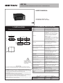
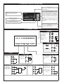
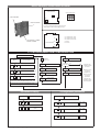
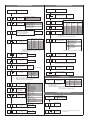
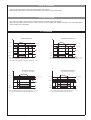
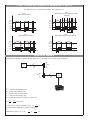
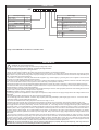
40F 96
CONFIGURABLE FREQUENCY INDICATOR - INTERCEPTOR
USER’S MANUAL
SOFTWARE VERSION 1.0x
code 81671B / edition 06 - 03/08
2 • TECHNICAL SPECIFICATIONS
1 • INSTALLATION
• Dimensions and cut-out: Panel mounting
Display
4 digit red LED’s, digit height 14mm
Keys
3 mechanical keys (Raise, Lower, F)
Accuracy
0.1% in autorange mode ± 1 digit with fixed f.s.
Main input
- mechanical contact, no voltage, configurable in
opening/closing, 100Hz filter insertable from
configuration
- from logic control under voltage with amplitude
0.5...30 Vdc, 6 mA max, for proximity PNP or
NPN (inductive or capacitive), encoder or
NAMUR 2 or 3 wires
- maximum frequency of input signal with duty
cycle 50% settable 1, 2, 3, 4, 10, 20, 40, 100 KHz
- from alternate control 30...500V peak, 1 mA max.
maximum frequency 10KHz
minimum frequency 0.5Hz in sinusoidal mode
Scale limits
-1999...9999 (settable decimal point)
Can be converted into engineering units by
inserting a multiplier or divisor (for example, for
display / intercept of rpm)
Sensor or transducer power supply
5Vdc, 12 Vdc, 120mA max
24 Vdc ± 10%, 50mA max filtered only
Alarms (set points)
Maximum of three configurable alarms:
absolute, deviation, symmetrical deviation.
Adjustable hysteresis
Alarm masking
- exclude on power-up
- latch reset from key and/or external contact
- insert delay filter (DON, DBI, DOF, DFO)
- set minimum intervention time
Relay contact
NO (NC) 5A, 250V a cosϕ=1
108
96
115
48
70
44,5
92
105
10
!
For correct and safe
installation, follow the
instructions and observe
the warnings contained
in this manual.
Panel mounting:
Fix the device with the bracket provided before making any electrical connections.
To mount two or more devices side by side, use the cut-out dimensions shown above.
CE MARKING: EMC (electromagnetic compatibility) conformity to EEC Directive
89/336/CEE with reference to the generic Standard EN50082-2 (immunity in industrial
environments) and EN50081-1 (emission in residential environments). BT (low voltage)
conformity to Directive 73/23/CEE as modified by Directive 93/68.
MAINTENANCE: Repairs must be done out only by trained and specialized personnel.
Cut power to the device before accessing internal parts.
Do not clean the case with hydrocarbon-based solvents (Petrol, Trichlorethylene, etc.).
Use of these solvents can reduce the mechanical reliability of the device. Use a cloth
dampened in ethyl alcohol or water to clean the external plastic case.
SERVICE: GEFRAN has a service department. The warranty excludes defects caused
by any use not conforming to these instructions.
81671B_MHW_40F96_0308_ENG
Logic output
type D 11Vdc, Rout = 220Ω (6V/20mA)
Triac output (option)
20...240Vac ±10%, 3A max.
Snubberless, inductive and resistive load
I2t = 128A2S
Logic input
Ri = 5,6KΩ (24V, 4mA), 1500V isolation
Logic input functions
configurable for alarm memory reset, hold, flash,
zero, selection of max., min. peak value, peakpeak
Analog retransmission (option)
4 to 20mA, max. 150 Ω load
Power supply (switching)
(standard) 100...240Vac/dc ±10% max 11,5VA
(optional) 11...27Vac/dc ±10% max 9VA
50/60Hz
Fuse (inside device, not
operator serviceable)
100 to 240Vac/dc - type T - 500mA - 250V
11 to 27Vac/dc - type T - 1.25A - 250V
Faceplate protection
IP65
Working / Storage temperatures
0 to 50°C / -20 to 70°C
Relative humidity
20 to 85%, non-condensing
Environmental conditions of use
for internal use only, altitude up to 2000m
Installation
Panel mounting, extractable from front
Weight
320g for the complete version
EMC conformity has been tested with the following connections
FUNCTION
Input
Power supply cable
Relay output cables
CABLE
1 mm2
1 mm2
1 mm2
LENGTH USED
3m
1m
3,5 m
1
3 • DESCRIPTION OF FACEPLATE
Flashing LED:
When frequency of input signal exceeds value
set for parameter PS
“Raise” and “Lower” keys:
These keys are used for any operation that
requires a numerical parameter to be raised or
lowered. ••The speed of change is proportional to
the time the key is pressed. •• The operation is
not cyclic: once the maximum (minimum) limit is
reached, there will be no further increase
(decrease) of the value, even if the key remains
pressed.
The keys can be configured to perform reset,
hold, display of the peak value, etc. as
determined by the ‘t.U.’ and ‘t.d.’ parameters on
the ‘In’ menu.
PV display: Indication of process variable
•• Indication of ‘HI’ or ‘Lo’ out of range
•• Display of configuration messages
Indication of output states:
OUT 1 (Alarm 1); OUT 2 (Alarm 2);
OUT 3 (Alarm 3)
Label with engineering units
Function key:
Gives access to different configuration stages ••
Confirms any parameter changes
4 • CONNECTIONS
• Outputs
Generic userconfigurable outputs
22
21
20
19
18
17
16
15
14
13
12
1
2
3
4
5
6
7
8
9
10
11
12
Out3
13
- relay 5A/250Vac
- logic 6V/20mA,
Rout = 220Ω
(for Out 1, Out 2)
- Triac
20...240Vac ±10%
3A max.
14
Out2
15
+
16
Out1
17
+
TRIAC
~
Line
~
Load
• Power supply
Standard:
100 to 240Vac/dc
±10%
Optional:
11 to 27Vac/dc ±10%
50/60Hz, 8VA max.
!
~
11
PWR
~
10
• Inputs
• Mechanical contact
Mechanical contact
no voltage max.
100 Hz.
• Logic input
4
Isolated digital
input 1500V
3
Ri = 5,6KΩ
(24V, 4mA)
2
6
• Retransmission output
Analog output for
retransmission
External
supply
5
8
-
7
+
4 to 20mA, Rmax.
150Ω
+
R
1
• Limit switch 3 wires /logic control
Inductive or
capacitive proximity
NPN or PNP
Input with sensitivity
0.5...30V, 6mA max
4
+
3
1
PNP
S
NPN
-
• Generator: AC
Signal from voltage
generator 30...500V
peak, 1 mA max.
4
+
2
2
• Limit switch 2 wires
Proximity
NAMUR 12V
3
+
2
1
-
3
+
-
4
To isolate the input,
remove FL1 and R20
from base
2
~
1
81671B_MHW_40F96_0308_ENG
Device structure: identification of boards
CPU BOARD + POWER
SUPPLY BOARD
Sensor power supply
OUTPUT BOARD
S1 S3
5V ON OFF
12V OFF ON
24V OFF OFF
S3 S1
FL1
R20
DISPLAY BOARD
FL1, R20 on component side are to be removed to
obtain isolation in case of high voltage AC input
S1
CPU BOARD + POWER
SUPPLY BOARD
S2
S1 = Status of Out 1 relay
S2 = Status of Out 2 relay
S3 = Status of Out 3 relay
B
A
B
A = Direct
B = Inverse
A
OUTPUT BOARD
S3
B
A
5 • PROGRAMMING and CONFIGURATION
LEVEL 1 DISPLAY
P.V.
F
Process variable
IF
Pressed for
approx. 2 sec.
PA
PA = 99
Information display
Alarm Setpoint Output 1
Alarm Setpoint Output 2
Alarm Setpoint Output 3
Password
NO
Keep the F key
pressed to browse
the menus.
YES
CF
Hysteresis parameters
Pr
Protection code
In
Input settings
U.C.
User calibration
Ou
Output settings
(*)
(*)
Release the F key
to enter the
displayed menu.
Press the F key to
access the
parameters.
Keep the F key
pressed to exit any
menu at any time.
(*) For deviation alarms the setpoint range is -999 ... 999
If the Inc, Dec, F keys are not pressed within 15 sec.,
the display returns to the P.V. value
• Information display
IF
Information display
• Configuration parameters
CF
Hysteresis parameters
Software version
Hysteresis for set point 1
-999 ... +999
scale points
Hysteresis for set point 2
-999 ... +999
scale points
Hysteresis for set point 3
-999 ... +999
scale points
Display of number of available
outputs
81671B_MHW_40F96_0308_ENG
3
• Input parameters
In
• Output parameters
Ou
Input settings
Output settings
0 to 3
Number of outputs
Input
configuration
0 Frequency - input NPN
1 Frequency - input PNP
2 AC input
1. t - 2. t - 3. t
Frequency meter
operating mode
With FP = 0 or 2: Period corresponds to
minimum frequency in input
With FP = 1 or 3: Sampling time,
TC = 0 update after 32 sec.
Value
Alarm type 1
0 Normal frequency value
1 Settable sampling time
2 Normal frequency value
with fixed full scale
3 Sampling time settable
with fixed full scale
0
1
2
3
4
5
6
7
Alarm type 2
0.0 ... 10.0sec
Direct
(max.)
Inverse
(min.)
Direct
Inverse
Direct
Inverse
Direct
Inverse
Direct
Inverse
Alarm type 3
Absolute
Normal
Relative to Symmetrical
previous
(window)
Absolute
Absolute
Relative
Relative
Absolute
Absolute
Relative
Relative
Normal
Normal
Normal
Normal
Symmetrical
Symmetrical
Symmetrical
Symmetrical
+8 to disable on power-up until first alarm
+16 to memorize
+32 to filter with F.O. mode (output filter mode)
Selection of full scale
frequency
0
1
2
3
4 (*)
5 (*)
6 (*)
7 (*)
Max. frequency
in input
1KHz
2KHz
4KHz
10KHz
20KHz
40KHz
80KHz
100KHz
Prescaler
ratio
1
2
4
2
4
8
16
32
0 not active: calculated status
is sent directly to relay
1 On delay (DON)
2 delay activation from
time of deactivation
of output (DBI)
3 Off delay (DOF)
4 Delay for activation
only at power-up
(DPO)
Output filter mode
+8 enable MU, dE parameters
(*) value shown indicates frequency /10 see
application example
+ 8 time base max. 99 min (default = 99 sec)
Multiplier
1 ... 255
delay for F.O.
0 to 99 min or sec
Divisor
1 ... 255
Minimum output pulse
0 to 99 sec
Disabled by setting value 0
Displayed if associated with at least one output
Main input filter
ON / OFF
ON = 100Hz filter
dP
0
1
2
3
Decimal point position for
full scale
Format
XXXX
XXX.X
XX.XX
X.XXX
Determines full scale of retransmitted output and alarms
N.B.: valid only for frequencies with fixed full scale;
automatic shift of Dp for higher frequencies
Selection of digital
input 1
Raise key function
(active only in
P.V.selection)
Lower key function
(active only in
P.V.selection)
0
1
2
3
4
5
6
7
8
9
10
11
12
13
14
15
4
None
Zero
Hold
Flash
Max. peak display
Min. peak display
Delta peak display
Peak memory reset
Zero + peak
memory reset
Alarms reset
Peak + alarms reset
Zero + alarms
reset
Peak + zero +
alarms reset
Output status OUT1
Output status OUT2
Output status OUT3
Minimum scale analog
repeat output
-1999 ... 9999
Maximum scale analog
repeat output
-1999 ... 9999
• Protection
Value
Pr
Protection code
0
1
2
3
Displayed
parameters
o.1, o.2, o.3
o.1, o.2
o.1
o.1
Modifiable
parameters
o.1, o.2, o.3
o.1, o.2
o.1
none
+4 to disable In and Ou pages
+8 to disable Cf page
+32 base configuration (the following parameters will not be displayed:
In: FI, L_L, H_L
Ou: On [forced to no. outputs present])
• User Calibration
U. C.
U.C.
1
CPU F Function
analog retransmission
output
Calibration of
minimum (*)
Low limit for the alarms
set point
-1999 ... 9999
High limit for the alarms
set point
-1999 ... 9999
Calibration of
maximum (*)
(*) when U.C. = 1 press keys ∆
analog output
∇ to calibrate
81671B_MHW_40F96_0308_ENG
• HOLD function
The input value and alarms are frozen while the logic input is active.
With the logic input active, a reset turns OFF both the relay outputs and the alarms latch.
• FLASH function
Input value is sampled; state of alarms is not transferred to outputs; outputs are “frozen”.
When the logic input is active the input value is “frozen” and the outputs are updated according to the calculated alarms
state, including the ones latched.
6 • ALARMS
Normal absolute alarm
Symmetrical absolute alarm
AL2
AL1 + [ H1 ]
AL2 + H2
AL1 + H1
AL1
AL1
AL1 - [ H1 ]
time
alarm 1
(*)
time
inverse
direct
alarm 2
For AL1 inverse absolute alarm (min.) with positive H1, 1 t = 1
(*) = OFF if disabling on power-on exists
For AL2 direct absolute alarm (max) with negative H2, 2 t = 0
For AL1 inverse absolute, symmetrical alarm with hysteresis H1, 1 t = 5
For AL1 direct absolute, symmetrical alarm with hysteresis H1, 1 t = 4
Normal deviation alarm
(AL1 absolute, AL2 relative)
Symmetrical deviation alarm
(AL1 absolute, AL2 relative)
AL1+AL2
AL1 + AL2 + H2
AL1+AL2
AL1+AL2+H2
AL1
AL1 + H1
AL1
AL1+H1
AL1-AL2
time
time
alarm 1
alarm 1
alarm 2
alarm 2
For AL1 direct absolute alarm (max) with negative H 1, 1 t = 0
For AL2 direct relative alarm (max) with negative H2, 2 t = 2
81671B_MHW_40F96_0308_ENG
For AL1 direct absolute alarm (max) with negative H1, 1 t = 0
For AL2 symmetrical deviation alarm H2, 2 t = 6
5
• Filter - outputs with reference to parameters F.0 and r.A
The diagrams refer to a normal absolute alarm with hysteresis H = 0
F.0 = 2
DBI = Delay in turning on output after output is
turned off
F.0 = 1
DON = Delayed activation
Alarm
setpoint
Alarm
setpoint
Variable
Variable
Output
Output
Alarm
Alarm
rA
rA
rA
time
t < rA
time
t > rA
t < rA
F.0 = 3
DOF = Delayed deactivation
F.0 = 4
DP0 = Delayed activation only at power-on
Alarm
setpoint
Alarm
setpoint
Variable
Variable
Output
Output
Alarm
Alarm
rA
rA
rA
rA
time
time
Applicative example
Configure the instrument to show motor axle speed in rpm, connected to an encoder as per the diagram.
MOTOR
Dpm
ωm
ENCODER
Dpe
Ke
ωe
f
Dpe = encoder pulley diameter [ m ]
Dpm = motor pulley diameter [ m ]
ωe = encoder angular velocity [ rpm ]
ωm = motor angular velocity [ rpm ]
Ke = number of pulses per encoder rev [ clock / rev ]
τ=
ωe
ωm
=
Dpm
Dpe
= drive ratio
f = frequency in input to instrument [ Hz ]
•
ωe
1
•
Ke
•
Ke
60
Ks is defined as multiplicative constant of instrument:
1
Value shown [ rpm ] = Ks • f = Ks •
6
•
60
ωm •
Dpm
Dpe
81671B_MHW_40F96_0308_ENG
Ks =
Ks numerator
Ks denominator
MU = Ks numerator • fs
dE = Ks denominator
where:
fs = full scale [ KHz ] (can be chosen from 1, 2, 4, 10, 20, 40, 100KHz according to max. frequency in input)
MU = multiplier
dE = divisor
These parameters can be set on the “In” menu
EXAMPLE 1
Dpm = 80 mm (motor pulley diameter)
Dpe = 160 mm (encoder pulley diameter)
Ke = 250 clock / rev = number of pulses per encoder rev
ωm maximum = 3000 rpm
Maximum frequency at input of the instrument must be determined to define full scale fs.
1
Dpm
fmax =
• (ωm maximum) •
• Ke = 6250 Hz
60
Dpe
fs = 10 KHz (value of parameter P.S corresponding to a full scale of 10KHz is 11)
12
Ks numerator
60 • Dpe 60 • 160
=
=
=
Ks =
25
Ks denominator
Ke • Dpm 250 • 80
After reducing the function to minimum terms, determine MU and dE (numerator and denominator):
P.S = 3, MU = 120, dE = 25
EXAMPLE 2
To show the rpms of a wheel with 250 pulses/rev, with max. frequency less than 1 kHz, set
FP = 0, P.S = 8 (full scale 1 KHz), MU = 6, dE = 25
EXAMPLE 3
For applications requiring greater precision of frequency value (with max. full scale 500 Hz), you can set a sampling time
greater than one second.
To show the frequency in pulses/second with fixed scale, with one decimal figure and with sampling time at a constant 5 sec,
set FP=3, tc =5.0 sec, P.S = 8 (full scale 1 KHz), MU = 1, dE = 5, dP = 1
EXAMPLE 4
Calculation of frequency displayed (F.v.) with a proximity input
With a full scale of 20KHz, the assigned prescaler ratio is 4; therefore the value shown is:
Input Frequency
F.v. =
Mu
•
Prescaler Ratio
dE
es.: Ps = 12 (Fmax. 20KHz)
Prescaler Ratio = 4
Mu = 3
dE = 7
Input Frequency
Frequenza
ingresso
F.v. =
3
•
4
= 214,2
7
7 • ACCESSORIES
• RS323 interface cable for configuration
N.B.: the PC configuration cable is supplied with the programming software.
WARNING: make the connection with the device powered and with inputs and
outputs disconnected.
• ORDER CODE
COD. 1108200
81671B_MHW_40F96_0308_ENG
Cable + Floppy
7
ORDER CODE
40F
96
4
Sensor power supply
Power supply
5Vdc, 120mA
05
0
11 to 27Vac/dc
12Vdc, 120mA
12
1
100 to 240Vac/dc
24Vdc, 50mA
24
Digital input / Retransmission output
Output 1, Output 2
Relay, Relay
RR
Relay, Static D2
RD
Triac, None
T0
0
None
1
Digital input
3
Digital input + Retransmission output 4...20mA
on max 150Ω
0
None
R
Relay
Output 3
Kindly contact GEFRAN for information on available codes.
• WARNINGS
!
WARNING: this symbol indicates danger.
It is seen near the power supply circuit and near high-voltage relay contacts.
Read the following warnings before installing, connecting or using the device:
• follow instructions precisely when connecting the device.
• always use cables that are suitable for the voltage and current levels indicated in the technical specifications.
• the device has no ON/OFF switch: it switches on immediately when power is turned on. For safety reasons, devices permanently connected to the power
supply require a two-phase disconnecting switch with proper marking. Such switch must be located near the device and must be easily reachable by the
user. A single switch can control several units.
• if the device is connected to electrically NON-ISOLATED equipment (e.g. thermocouples), a grounding wire must be applied to assure that this
connection is not made directly through the machine structure.
• if the device is used in applications where there is risk of injury to persons and/or damage to machines or materials, it MUST be used with auxiliary alarm
units. You should be able to check the correct operation of such units during normal operation of the device.
• before using the device, the user must check that all device parameters are correctly set in order to avoid injury to persons and/or damage to property.
• the device must NOT be used in inflammable or explosive environments. It may be connected to units operating in such environments only by means of
suitable interfaces in conformity to local safety regulations.
• the device contains components that are sensitive to static electrical discharges. Therefore, take appropriate precautions when handling electronic circuit
boards in order to prevent permanent damage to these components.
Installation: installation category II, pollution level 2, double isolation
• power supply lines must be separated from device input and output lines; always check that the supply voltage matches the voltage indicated on the
device label.
• install the instrumentation separately from the relays and power switching devices
• do not install high-power remote switches, contactors, relays, thyristor power units (particularly if “phase angle” type), motors, etc... in the same cabinet.
• avoid dust, humidity, corrosive gases and heat sources.
• do not close the ventilation holes; working temperature must be in the range of 0...50°C.
If the device has faston terminals, they must be protected and isolated; if the device has screw terminals, wires should be attached at least in pairs.
• Power: supplied from a disconnecting switch with fuse for the device section; path of wires from switch to devices should be as straight as possible; the
same supply should not be used to power relays, contactors, solenoid valves, etc.; if the voltage waveform is strongly distorted by thyristor switching units
or by electric motors, it is recommended that an isolation transformer be used only for the devices, connecting the screen to ground; it is important for the
electrical system to have a good ground connection; voltage between neutral and ground must not exceed 1V and resistance must be less than 6Ohm; if
the supply voltage is highly variable, use a voltage stabilizer for the device; use line filters in the vicinity of high frequency generators or arc welders;
power supply lines must be separated from device input and output lines; always check that the supply voltage matches the voltage indicated on the
device label.
• Input and output connections: external connected circuits must have double insulation; to connect analog inputs (TC, RTD) you have to: physically
separate input wiring from power supply wiring, from output wiring, and from power connections; use twisted and screened cables, with screen connected
to ground at only one point; to connect adjustment and alarm outputs (contactors, solenoid valves, motors, fans, etc.), install RC groups (resistor and
capacitor in series) in parallel with inductive loads that work in AC (Note: all capacitors must conform to VDE standards (class x2) and support at least 220
VAC. Resistors must be at least 2W); fit a 1N4007 diode in parallel with the coil of inductive loads that operate in DC.
GEFRAN spa will not be held liable for any injury to persons and/or damage to property deriving from tampering, from any incorrect or
erroneous use, or from any use not conforming to the device specifications.
8
81671B_MHW_40F96_0308_ENG


![Indicateurs (PDF/782Ko) [F]](http://vs1.manualzilla.com/store/data/006364555_1-61d6515c96ce437ed2545f3e53fb26c1-150x150.png)