1
Figure
Section
Description
Page
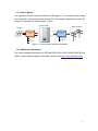
Figure 1-1 Solar system operation illustration ................................................. 8
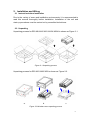
Figure 2-1 Unpacking process ........................................................................ 9
Figure 2-2 Wooden case unpacking process .................................................. 9
Figure 2-3 The identification label ................................................................. 10
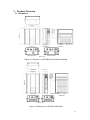
Figure 3-1 Dimension of RPI-M8/ M10/ M12/ M15A/ M20A .......................... 11
Figure 3-2 Dimension of RPI-M15/ M20/ M30 ............................................... 11
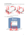
Figure 3-3 Inverter exterior objects ............................................................... 12
Figure 3-4 LCD display and control panel ..................................................... 12
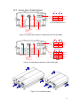
Figure 3-5 Input/Output interfaces of M8/ M10/ M12/ M15A/ M20A .............. 13
Figure 3-6 Input/Output interfaces of M15/ M20/ M30................................... 13
Figure 3-7 Air outlet illustration ..................................................................... 13
Figure 4-1 Screw the mounting bracket ........................................................ 15
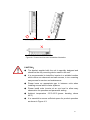
Figure 4-2 Correct and incorrect installation illustration ................................ 16
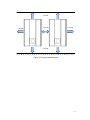
Figure 4-3 Proper installation gap ................................................................. 17
Figure 5-1 Connection of a system for floating DC inputs ............................. 18
Figure 5-2 Connection of system with positive/negative ground ................... 19
Figure 5-3 Stripping the wire ......................................................................... 21
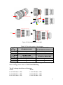
Figure 5-4 AC plug illustrationfor M8/ M10/ M12/ M15/ M15A/ M20/ M20A. . 22
Figure 5-5 AC plug illustration for M30 .......................................................... 23
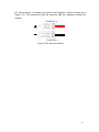
Figure 5-6 DC Wiring illustration ................................................................... 25
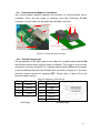
Figure 5-7 Communication module ............................................................... 26
Figure 5-8 Multi-inverter connection illustration ............................................ 27
Figure 5-9 Dry contact port & Assignments ................................................... 28
Figure 6-1 Power vs. frequency characteristic .............................................. 30
Figure 6-2 cosφ(P) characteristic .................................................................. 31
Figure 6-3 Q(U) characteristic. ...................................................................... 32
Figure 6-4 Borderlines of the voltage profile of a type-2 generating plant at the
network connection point .............................................................................. 34
Figure 6-5 FRT characteristic ........................................................................ 34
Figure 7-1 LCD display &control panel ......................................................... 35
Figure 7-2 Select county page ...................................................................... 36
Figure 7-3 Select language page .................................................................. 36
Figure 7-4 Home page .................................................................................. 37
Figure 7-5 Menu page................................................................................... 37
3