1
Water and Wastewater Accelerator Toolkit
Quick Start
Important User Information
Solid state equipment has operational characteristics differing from those of electromechanical equipment. Safety Guidelines
for the Application, Installation and Maintenance of Solid State Controls (publication SGI-1.1 available from your local Rockwell
Automation sales office or online at http://www.rockwellautomation.com/literature/) describes some important differences
between solid state equipment and hard-wired electromechanical devices. Because of this difference, and also because of the
wide variety of uses for solid state equipment, all persons responsible for applying this equipment must satisfy themselves that
each intended application of this equipment is acceptable.
In no event will Rockwell Automation, Inc. be responsible or liable for indirect or consequential damages resulting from the use
or application of this equipment.
The examples and diagrams in this manual are included solely for illustrative purposes. Because of the many variables and
requirements associated with any particular installation, Rockwell Automation, Inc. cannot assume responsibility or liability for
actual use based on the examples and diagrams.
No patent liability is assumed by Rockwell Automation, Inc. with respect to use of information, circuits, equipment, or software
described in this manual.
Reproduction of the contents of this manual, in whole or in part, without written permission of Rockwell Automation, Inc., is
prohibited.
Throughout this manual, when necessary, we use notes to make you aware of safety considerations.
WARNING
Identifies information about practices or circumstances that can cause an explosion in a hazardous environment,
which may lead to personal injury or death, property damage, or economic loss.
IMPORTANT
Identifies information that is critical for successful application and understanding of the product.
ATTENTION
Identifies information about practices or circumstances that can lead to personal injury or death, property damage,
or economic loss. Attentions help you identify a hazard, avoid a hazard, and recognize the consequence
SHOCK HAZARD
Labels may be on or inside the equipment, for example, a drive or motor, to alert people that dangerous voltage may
be present.
BURN HAZARD
Labels may be on or inside the equipment, for example, a drive or motor, to alert people that surfaces may reach
dangerous temperatures.
Allen-Bradley, Rockwell Automation, and TechConnect are trademarks of Rockwell Automation, Inc.
Trademarks not belonging to Rockwell Automation are property of their respective companies.
Table of Contents
Table of Contents
Preface
Introduction . . . . . . . . . . . . . . . . . . . . . . . . . . . . . . . . . . . . . . . . . . . . . . . 5
Required Software . . . . . . . . . . . . . . . . . . . . . . . . . . . . . . . . . . . . . . . . . . 7
Chapter 1
System Specification
Introduction . . . . . . . . . . . . . . . . . . . . . . . . . . . . . . . . . . . . . . . . . . . . . . . 9
Procurement Specifications . . . . . . . . . . . . . . . . . . . . . . . . . . . . . . . . . . . 9
Customizing Procurement Documents . . . . . . . . . . . . . . . . . . . . . 10
System Architecture Drawings . . . . . . . . . . . . . . . . . . . . . . . . . . . . . . . 11
Accessing System Architecture Drawings. . . . . . . . . . . . . . . . . . . . 11
Customizing System Architecture Drawings . . . . . . . . . . . . . . . . . 11
Water and Wastewater Treatment Plant Drawings. . . . . . . . . . . . . . . . 12
Lift Station System Architecture Drawing . . . . . . . . . . . . . . . . . . . 12
Dosing Pump System Architecture Drawing . . . . . . . . . . . . . . . . . 14
Primary Treatment System Architecture Drawing . . . . . . . . . . . . . 15
Headworks System Architecture Drawing . . . . . . . . . . . . . . . . . . . 17
Secondary Treatment System Architecture Drawing . . . . . . . . . . . 19
Solids Handling System Architecture Drawing . . . . . . . . . . . . . . . 21
Water Treatment Plant Drawings . . . . . . . . . . . . . . . . . . . . . . . . . . . . . 23
Raw Water Intake Pump Station System Architecture Drawing . . 23
Separation Station System Architecture Drawing . . . . . . . . . . . . . 25
High Service Pump Station System Architecture Drawing . . . . . . 27
Pump Controller Station Architecture Drawing. . . . . . . . . . . . . . . . . . 28
Additional Resources . . . . . . . . . . . . . . . . . . . . . . . . . . . . . . . . . . . . . . . 29
Chapter 2
Hardware Design
Introduction . . . . . . . . . . . . . . . . . . . . . . . . . . . . . . . . . . . . . . . . . . . . . . 31
Hardware Drawings . . . . . . . . . . . . . . . . . . . . . . . . . . . . . . . . . . . . . . . . 31
Water and Wastewater Treatment Plant Hardware Drawings . . . . . . . 31
Lift Station Hardware Drawings . . . . . . . . . . . . . . . . . . . . . . . . . . . 32
Dosing Pump Hardware Drawings. . . . . . . . . . . . . . . . . . . . . . . . . 36
Water Treatment Plant Hardware Drawings . . . . . . . . . . . . . . . . . . . . 40
Raw Water Intake Pump Station System Hardware Drawings . . . 40
Pump Controller Station Hardware Drawings . . . . . . . . . . . . . . . . . . . 44
CAD Figures. . . . . . . . . . . . . . . . . . . . . . . . . . . . . . . . . . . . . . . . . . . . . . 50
How to Access Additional CAD Figures from the Website . . . . . 51
Additional Resources . . . . . . . . . . . . . . . . . . . . . . . . . . . . . . . . . . . . . . . 51
Chapter 3
Application Engineering
1Publication IASIMP-QS014C-EN-P - February 2013
Additional Resources . . . . . . . . . . . . . . . . . . . . . . . . . . . . . . . . . . . . . . . 53
Process Library Module . . . . . . . . . . . . . . . . . . . . . . . . . . . . . . . . . . . . . 53
Using the Process Library Module . . . . . . . . . . . . . . . . . . . . . . . . . 55
Reuse Code. . . . . . . . . . . . . . . . . . . . . . . . . . . . . . . . . . . . . . . . . . . . 55
Provide an Easier to Understand Interface . . . . . . . . . . . . . . . . . . 55
Intellectual Property Protection . . . . . . . . . . . . . . . . . . . . . . . . . . . 56
Using Add-On Instructions . . . . . . . . . . . . . . . . . . . . . . . . . . . . . . . . . . 57
1
Alarm (P_Alarm) . . . . . . . . . . . . . . . . . . . . . . . . . . . . . . . . . . . . . . . 57
Analog Input basic Instruction (P_Aln) . . . . . . . . . . . . . . . . . . . . . 58
Digital Input Instruction (P_Dln) . . . . . . . . . . . . . . . . . . . . . . . . . . 61
Interlock Instruction (P_Intlk) . . . . . . . . . . . . . . . . . . . . . . . . . . . . 63
Mode (P_Mode). . . . . . . . . . . . . . . . . . . . . . . . . . . . . . . . . . . . . . . . 65
Motor (P_Motor) . . . . . . . . . . . . . . . . . . . . . . . . . . . . . . . . . . . . . . . 68
Permissive (P_Perm) . . . . . . . . . . . . . . . . . . . . . . . . . . . . . . . . . . . . 71
Reset (P_Reset) . . . . . . . . . . . . . . . . . . . . . . . . . . . . . . . . . . . . . . . . 72
Reset Inhibit (P_ResetInh) . . . . . . . . . . . . . . . . . . . . . . . . . . . . . . . 73
Run Time (P_RunTime) . . . . . . . . . . . . . . . . . . . . . . . . . . . . . . . . . 74
Motor Operated Valve (P_ValveMO) . . . . . . . . . . . . . . . . . . . . . . 76
Variable Speed Drive (P_VSD). . . . . . . . . . . . . . . . . . . . . . . . . . . . 80
WWWAT CD Applications . . . . . . . . . . . . . . . . . . . . . . . . . . . . . . . . . 83
Water/Wastewater Treatment Application Framework . . . . . . . . 83
Inputs and Outputs . . . . . . . . . . . . . . . . . . . . . . . . . . . . . . . . . . . . . 86
AOIs . . . . . . . . . . . . . . . . . . . . . . . . . . . . . . . . . . . . . . . . . . . . . . . . . 88
Using the Process Modules . . . . . . . . . . . . . . . . . . . . . . . . . . . . . . . 89
User Modules . . . . . . . . . . . . . . . . . . . . . . . . . . . . . . . . . . . . . . . . . . 89
Water and Wastewater Treatment Plant Applications . . . . . . . . . . . . . 90
Lift Station System Application . . . . . . . . . . . . . . . . . . . . . . . . . . . 90
Control Description. . . . . . . . . . . . . . . . . . . . . . . . . . . . . . . . . . . . . 93
Alarms . . . . . . . . . . . . . . . . . . . . . . . . . . . . . . . . . . . . . . . . . . . . . . 101
Customization . . . . . . . . . . . . . . . . . . . . . . . . . . . . . . . . . . . . . . . . 102
Resets . . . . . . . . . . . . . . . . . . . . . . . . . . . . . . . . . . . . . . . . . . . . . . . 104
Adding or Removing Pumps. . . . . . . . . . . . . . . . . . . . . . . . . . . . . 109
Dosing Pumps Application . . . . . . . . . . . . . . . . . . . . . . . . . . . . . . 113
Control Description. . . . . . . . . . . . . . . . . . . . . . . . . . . . . . . . . . . . 115
Alarms . . . . . . . . . . . . . . . . . . . . . . . . . . . . . . . . . . . . . . . . . . . . . . 119
Customization of the Dosing Pumps Application . . . . . . . . . . . . 120
Additional Flow Pacing . . . . . . . . . . . . . . . . . . . . . . . . . . . . . . . . . 123
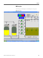
Headworks Application . . . . . . . . . . . . . . . . . . . . . . . . . . . . . . . . . 124
Process Description . . . . . . . . . . . . . . . . . . . . . . . . . . . . . . . . . . . . 126
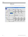
HMI Description . . . . . . . . . . . . . . . . . . . . . . . . . . . . . . . . . . . . . . 127
Control Description - Mechanical Bar Screen Numbers 1 and 2 129
Alarms . . . . . . . . . . . . . . . . . . . . . . . . . . . . . . . . . . . . . . . . . . . . . . 134
Reporting Equipment Run Times. . . . . . . . . . . . . . . . . . . . . . . . . 135
Customization of the Headworks Application . . . . . . . . . . . . . . . 136
Secondary Application. . . . . . . . . . . . . . . . . . . . . . . . . . . . . . . . . . 137
Process Description . . . . . . . . . . . . . . . . . . . . . . . . . . . . . . . . . . . . 140
HMI Description . . . . . . . . . . . . . . . . . . . . . . . . . . . . . . . . . . . . . . 142
Control Description - Blower BLR-400 . . . . . . . . . . . . . . . . . . . . 144
Alarms . . . . . . . . . . . . . . . . . . . . . . . . . . . . . . . . . . . . . . . . . . . . . . 148
Reporting . . . . . . . . . . . . . . . . . . . . . . . . . . . . . . . . . . . . . . . . . . . . 150
Customization of the Secondary Application. . . . . . . . . . . . . . . . 151
Solids Application . . . . . . . . . . . . . . . . . . . . . . . . . . . . . . . . . . . . . 152
Process Description . . . . . . . . . . . . . . . . . . . . . . . . . . . . . . . . . . . . 155
2
Publication IASIMP-QS014C-EN-P - February 2013
HMI Description . . . . . . . . . . . . . . . . . . . . . . . . . . . . . . . . . . . . . . 156
Control Description. . . . . . . . . . . . . . . . . . . . . . . . . . . . . . . . . . . . 158
Alarms . . . . . . . . . . . . . . . . . . . . . . . . . . . . . . . . . . . . . . . . . . . . . . 162
Reporting . . . . . . . . . . . . . . . . . . . . . . . . . . . . . . . . . . . . . . . . . . . . 164
Customization of the Solids Application . . . . . . . . . . . . . . . . . . . 165
Flushing System Application. . . . . . . . . . . . . . . . . . . . . . . . . . . . . 168
HMI Description . . . . . . . . . . . . . . . . . . . . . . . . . . . . . . . . . . . . . . 176
Select Flush Mode . . . . . . . . . . . . . . . . . . . . . . . . . . . . . . . . . . . . . 177
"Return all to Auto" Button . . . . . . . . . . . . . . . . . . . . . . . . . . . . . 178
Simulation Mode . . . . . . . . . . . . . . . . . . . . . . . . . . . . . . . . . . . . . . 178
Chemical Feed System Application. . . . . . . . . . . . . . . . . . . . . . . . 178
Process Description . . . . . . . . . . . . . . . . . . . . . . . . . . . . . . . . . . . . 178
Control Description. . . . . . . . . . . . . . . . . . . . . . . . . . . . . . . . . . . . 179
Chemical Feed Mixers . . . . . . . . . . . . . . . . . . . . . . . . . . . . . . . . . . 196
HMI Description . . . . . . . . . . . . . . . . . . . . . . . . . . . . . . . . . . . . . . 197
Water Treatment Plant Applications. . . . . . . . . . . . . . . . . . . . . . . . . . 199
Raw Water Intake Application . . . . . . . . . . . . . . . . . . . . . . . . . . . 199
Process Description . . . . . . . . . . . . . . . . . . . . . . . . . . . . . . . . . . . . 202
HMI Description . . . . . . . . . . . . . . . . . . . . . . . . . . . . . . . . . . . . . . 203
Control Description. . . . . . . . . . . . . . . . . . . . . . . . . . . . . . . . . . . . 205
Alarms . . . . . . . . . . . . . . . . . . . . . . . . . . . . . . . . . . . . . . . . . . . . . . 209
Reporting Equipment Run Times. . . . . . . . . . . . . . . . . . . . . . . . . 211
Customization of the Raw Water Intake Application . . . . . . . . . 212
Separation Application . . . . . . . . . . . . . . . . . . . . . . . . . . . . . . . . . 213
Process Description . . . . . . . . . . . . . . . . . . . . . . . . . . . . . . . . . . . . 215
HMI Description . . . . . . . . . . . . . . . . . . . . . . . . . . . . . . . . . . . . . . 216
Control Description. . . . . . . . . . . . . . . . . . . . . . . . . . . . . . . . . . . . 218
Alarms . . . . . . . . . . . . . . . . . . . . . . . . . . . . . . . . . . . . . . . . . . . . . . 220
Reporting . . . . . . . . . . . . . . . . . . . . . . . . . . . . . . . . . . . . . . . . . . . . 222
Customization of the Separation Application . . . . . . . . . . . . . . . 222
High Service Pump Station Application . . . . . . . . . . . . . . . . . . . . 224
Process Description . . . . . . . . . . . . . . . . . . . . . . . . . . . . . . . . . . . . 226
HMI Description . . . . . . . . . . . . . . . . . . . . . . . . . . . . . . . . . . . . . . 227
Control Description. . . . . . . . . . . . . . . . . . . . . . . . . . . . . . . . . . . . 229
Alarms . . . . . . . . . . . . . . . . . . . . . . . . . . . . . . . . . . . . . . . . . . . . . . 231
Reporting . . . . . . . . . . . . . . . . . . . . . . . . . . . . . . . . . . . . . . . . . . . . 233
Customization of the High Service Pump Station Application . . 234
Pump Controller Station . . . . . . . . . . . . . . . . . . . . . . . . . . . . . . . . . . . 234
GChapter 4
Installation and Commissioning
Publication IASIMP-QS014C-EN-P - February 2013
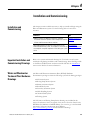
Installation and Commissioning . . . . . . . . . . . . . . . . . . . . . . . . . . . . . 271
Important Installation and Commissioning Drawings . . . . . . . . . . . . 271
Water and Wastewater Treatment Plant Hardware Drawings . . . . . . 271
Lift Station Hardware Drawings . . . . . . . . . . . . . . . . . . . . . . . . . . 272
Dosing Pump Hardware Drawings. . . . . . . . . . . . . . . . . . . . . . . . 277
Water Treatment Plant Hardware Drawings . . . . . . . . . . . . . . . . . . . 281
3
Raw Water Intake System Hardware Drawings . . . . . . . . . . . . . . 281
Pump Controller Station Hardware Drawings . . . . . . . . . . . . . . . . . . 286
Chapter 5
Maintenance and Repair
Introduction . . . . . . . . . . . . . . . . . . . . . . . . . . . . . . . . . . . . . . . . . . . . . 295
Important Maintenance and Repair Drawings . . . . . . . . . . . . . . . . . . 295
Water and Wastewater Treatment Plant Hardware Drawings . . . . . . 295
Lift Station Hardware Drawings . . . . . . . . . . . . . . . . . . . . . . . . . . 296
Dosing Pump Hardware Drawings. . . . . . . . . . . . . . . . . . . . . . . . 301
Water Treatment Plant Hardware Drawings . . . . . . . . . . . . . . . . . . . 305
Raw Water Intake System Hardware Drawings . . . . . . . . . . . . . . 305
Pump Controller Station Hardware Drawings . . . . . . . . . . . . . . . . . . 310
Appendix A
Additional Resources
4
Website Resources . . . . . . . . . . . . . . . . . . . . . . . . . . . . . . . . . . . . . . . . 319
Documentation Resources. . . . . . . . . . . . . . . . . . . . . . . . . . . . . . . . . . 320
Publication IASIMP-QS014C-EN-P - February 2013
Preface
Introduction
The Water and Wastewater Quick Start Guide contains step by step
instructions for using the Water and Wastewater Accelerator Toolkit
(WWWAT). This toolkit is a valuable resource for designing, installing,
operating, and maintaining a Water and Wastewater project. The WWWAT
resides on a CD containing:
Pre-configured files
Selection tools
Examples of using a Logix Controller to connect to multiple devices
(PowerFlex AC drives, motors, and HMI terminals) over EtherNet/IP
and DeviceNet networks.
System architecture drawings
CAD drawings
Basic status, control, and diagnostic logic
FactoryTalk View SE faceplates
A new stand-alone Pump Controller Station Application based on the
MicroLogix 1400 and PanelView Component C600 is also now included.
With these tools and the built-in best-practices design, the system designer is
free to focus on their machine control design rather than designing overhead
tasks.
Contact your local Rockwell Automation distributor or sales representative for
a copy of the WWWATC CD (Publication IASIMP-SP012). You can also go
to the Rockwell Automation Integrated Architecture Tools Website,
http://www.ab.com/go/iatools and download the appropriate tools.
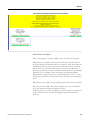
IMPORTANT
5Publication IASIMP-QS014C-EN-P - February 2013
Before using this guide and the contents of the WWWAT CD,
read the Terms and Conditions README.pdf on the CD.
5
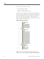
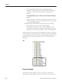
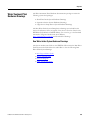
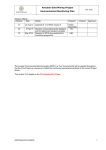
Preface
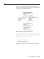
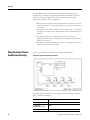
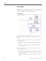
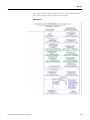
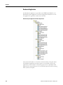
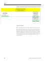
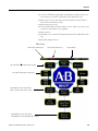
Use this flow chart to determine which chapters in this guide apply to your
role in the Water and Wastewater project. Each chapter is organized according
to the various Water and Wastewater project roles.
Water and Wastewater Quick Start Guide Chapter Organization
Once you've identified which section pertains to your role, read that section.
Each section contains information on the existing documents’ content, usage,
and location. All of this material is provided to help you get started on your
project. This guide answers questions such as:
What hardware do I need?
How should it be programmed?
What software standards should I use?
How do I install this hardware?
See Appendix A for further resources and updates to existing information.
6
Publication IASIMP-QS014C-EN-P - February 2013
Preface
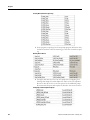
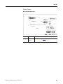
Required Software
To utilize the applications provided in this Accelerator, the following software
is required:
Rockwell Automation
Software
Catalog Number
Version
Required For
RSlogix 5000
9324-RLD300RNE
17 or later
All Water and
Wastewater Controller
Applications
9701-VWSBxxxAENE
5.0 or later PanelView Plus
Applications
Control Flash
BootP/DHCP Utility
(EtherNet.IP)
RSLinx Classic
FactoryTalk View Studio
Site Edition
FactoryTalk Services
(xxx=number of
screens required for
the application)
RSLinx Enterprises
RSLinx Classic
Publication IASIMP-QS014C-EN-P - February 2013
7
Preface
Notes:
8
Publication IASIMP-QS014C-EN-P - February 2013
Chapter
1
System Specification
Introduction
Use this chapter to learn about the Water and Wastewater product portfolio.
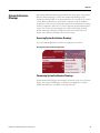
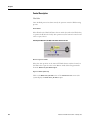
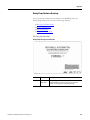
Procurement
Specifications
The Water and Wastewater Accelerator Toolkit (WWWAT) CD contains
procurement documents to help you develop the appropriate Request for
Proposals (RFPs). We suggest that you copy and then paste these documents
directly into your bid documentation package. Our objective is to save you
time when writing these specifications.
Most of the hardware referenced on the CD has an associated procurement
specification. This hardware includes:
ControlLogix controllers
L2x Compactions controllers
PanelView Plus HMIs
PowerFlex 70 variable frequency drives
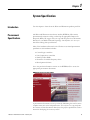
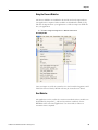
Development Software
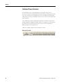
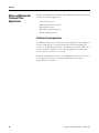
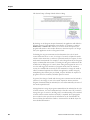
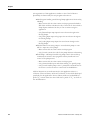
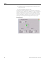
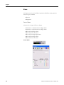
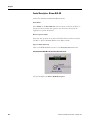
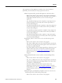
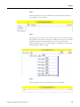
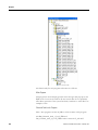
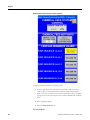
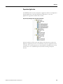
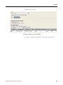
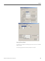
Go to the product information section on the WWWAT CD to access the
appropriate procurement documents
WWWAT CD Product Information Menu
A procurement document can save you time by eliminating the need to create
complex items such as the bid specification. You only have to copy and paste
the contents of these documents directly into the project specifications section
instead of developing the content yourself.
9Publication IASIMP-QS014C-EN-P - February 2013
9
Chapter 1
Customizing Procurement Documents
Typically, the procurement documents do not require editing. However, since
all RFP's are unique in their requirements, you many need to use the following
procedure to make the necessary changes.
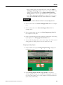
1. Identify the section of the specification or RFP that is required. For
example, is it a section on variable frequency drives or controllers?
2. Locate the appropriate procurement specification on the WWWAT CD.
3. Copy and paste the content of the procurement document into the
specification or RFP.
4. Check the introduction of the new section that you've pasted into the
specification. It is possible that you will need to change the introduction
to better integrate into the existing document. The specification or RFP
will already have a format and style, but some adjustments will be
necessary to adhere to this style.
5. Check the format of the section numbering. Ensure that the
procurement specification that you included matches the section
numbering and does not disrupt the progression of section or page
numbering.
10
Publication IASIMP-QS014C-EN-P - February 2013
Chapter 1
System Architecture
Drawings
The system architecture drawings provide value in many stages of the project
lifecycle. While specifying a system, these architecture drawings can be
included in either the RFP or the proposal itself as an overview of the control
system. With one illustration, they provide a summary of all the hardware
components of the control system and the method of communication among
all those components. They also let control engineers quickly understand the
scope of the control system and grasp the control technologies involved.
System architecture drawings are important early in the project life-cycle
because they efficiently summarize the control strategy.
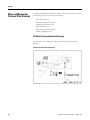
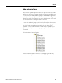
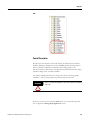
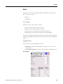
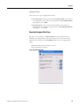
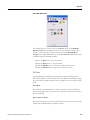
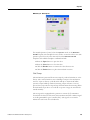
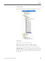
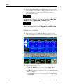
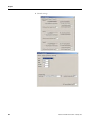
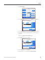
Accessing System Architecture Drawings
Go to the desired application and select the application of interest.
Selecting the System Architecture Application
Customizing System Architecture Drawings
System architecture drawings are intended to be used as a basis for your system
design. They require modifications to illustrate your application correctly.
Include the drawings in your RFP or the proposal itself.
Publication IASIMP-QS014C-EN-P - February 2013
11
Chapter 1
Water and Wastewater
Treatment Plant Drawings
The Water and Wastewater Treatment Plant documentation package contains
the following system-level architectural drawings:
Lift Station System
Dosing Pump Station System
Primary Treatment System
Headworks System
Secondary Treatment System
Solids Handling System
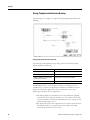
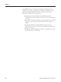
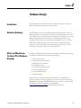
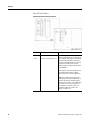
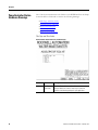
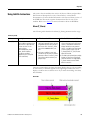
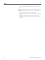
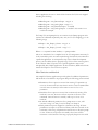
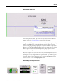
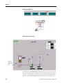
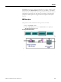
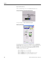
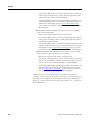
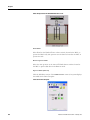
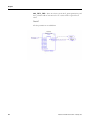
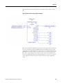
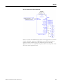
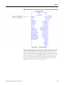
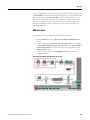
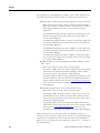
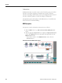
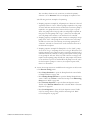
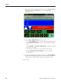
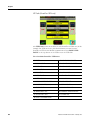
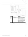
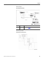
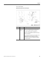
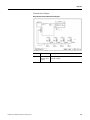
Lift Station System Architecture Drawing
The following is an example of a typical Lift Station System Architecture
Drawing.
Lift Station System Architecture Drawing
12
Publication IASIMP-QS014C-EN-P - February 2013
Chapter 1
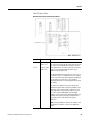
The following table describes the key design points of the Lift Station System
Architecture Drawing.
Hardware
Description
L23 Processor
Controls the Lift Station
EtherNet IP
Enables the HMI, hard drive, and system controller to
communicate with each other
PanelView Plus
Human Machine Interface (HMI)
PowerFlex 70
Drives the pumps
DeviceNet
Controls I/O and other devices
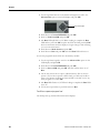
Esteem Wireless Modem Connects the Lift Station to the Supervisory System
The WWWAT CD contains architecture drawings that are only intended to be
the basis for your application. Hardware modifications may be required to
fulfill your application needs. Consider these points when designing the
hardware for your application.
The HMI shown in the Lift Station Architecture Drawing is a
PanelView Plus 600 with a keyboard. Do you have another size screen
preference? Do you prefer display only with no keypad?
The pumps in this application are controlled via contactors. Optionally
shown are a PowerFlex 70 Drives to run the pumps, and higher
horsepower drives may require a different PowerFlex series drive.
I/O on this sheet is optionally shown as both Point I/O and Compact
Block I/O. Select an I/O style based on your requirements.
The number of PanelView could change based on the operating
procedures at your facility. Simply add more PanelView stations as
needed.
The number of contactors or PowerFlex 70 Drives could change based
on the number of pumps in the Lift Station. Add more contactors or
PowerFlex Drives, as needed.
The Ethernet Switch shown has a limited number of ports. Select the
appropriate Stratix switch as required for the number of EtherNet/IP
devices in the system.
IP addresses and node numbers should be included on this drawing.
They are specific to your application.
Publication IASIMP-QS014C-EN-P - February 2013
13
Chapter 1
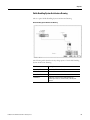
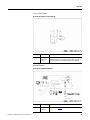
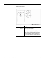
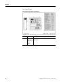
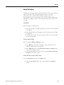
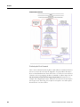
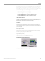
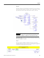
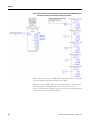
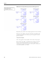
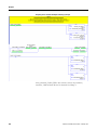
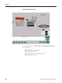
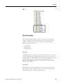
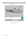
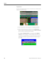
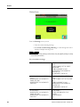
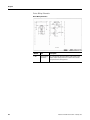
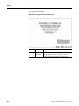
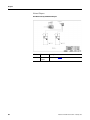
Dosing Pump System Architecture Drawing
The following is an example of a typical Dosing Pump System Architecture
Drawing.
Dosing Pump System Architecture Drawing
The following table describes the key design points of the Dosing Pump
System Architecture Drawing.
Hardware
Description
ControlLogix Processor
Controls the Dosing Pumps
1756 Series
Controls I/O
Remote 1756 Chassis with Analog
and Discrete I/O Devices
Communicates with the Dosing Pumps
ControlNet
Communicates with the Dosing Pump System
The WWWAT CD also contains System Architecture Drawings that are
intended only to support your application. Hardware modifications may be
required to fulfill your application needs. Consider these points when
designing the hardware for your application:
The Dosing Pumps are assumed to be run by a third party supplied
controller. The ControlLogix interfaces to it via a remote chassis. This
scenario should be reviewed and adjusted based on the strategy for the
specific dosing pump control.
The input and output card configuration in the remote chassis must be
determined based on the specific needs of the inputs and outputs
located in the proximity of that chassis.
14
Publication IASIMP-QS014C-EN-P - February 2013
Chapter 1
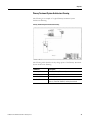
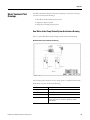
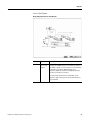
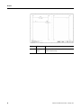
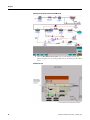
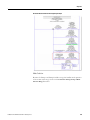
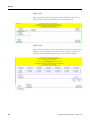
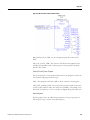
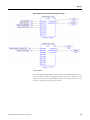
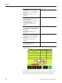
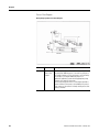
Primary Treatment System Architecture Drawing
The following is an example of a typical Primary Treatment System
Architecture Drawing.
.Primary Treatment System Architecture Drawing
The following table describes the key design points of the Primary Treatment
System Architecture Drawing.
Publication IASIMP-QS014C-EN-P - February 2013
Hardware
Description
ControlLogix Processor
Controls the Primary Treatment System
1756 Series
Controls I/O
PowerFlex 700 Drive
Drives the pumps
EtherNet/IP
Establishes a communication path between the ControlLogix
Processor, PowerFlex 700 Drive, and the plant network
15
Chapter 1
The WWWAT CD also contains System Architecture Drawings that are
intended only to support your application. Hardware modifications may be
required to fulfill your application needs. Consider these points when
designing the hardware for your application:
Each specific site must determine the 1756 Chassis I/O card
configuration based on the specific needs of the I/O devices adjacent to
that chassis.
The number of PowerFlex 700 Drives may change based on the number
of pumps in the Primary Treatment System. Add more drives as needed.
The Ethernet Switch has a limited number of ports. Select the
appropriate Stratix switch as required for the number of EtherNet/IP
devices in the system.
IP addresses and node numbers are unique to the application and you
must include them on this drawing.
16
Publication IASIMP-QS014C-EN-P - February 2013
Chapter 1
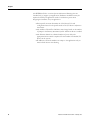
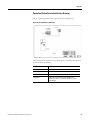
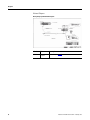
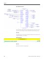
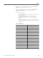
Headworks System Architecture Drawing
The following is an example of a typical Headworks System Architecture
Drawing.
Headworks System Architecture Drawing
The following table describes the key design points of the Headworks System
Architecture Drawing.
Publication IASIMP-QS014C-EN-P - February 2013
Hardware
Description
ControlLogix Processor
Controls the Headworks System
1756 Series
Controls I/O
PowerFlex 700 Drive
Drives the motors
EtherNet/IP
Establishes a communication path between the
ControlLogix Processor, PowerFlex 700 Drive, and the
plant network
17
Chapter 1
The WWWAT CD also contains System Architecture Drawings that are
intended only to support your application. Hardware modifications may be
required to fulfill your application needs. Consider these points when
designing the hardware for your application:
Each specific site must determine the 1756 Chassis I/O card
configuration based on the specific needs of the I/O devices adjacent to
that chassis.
The number of PowerFlex 700 Drives may change based on the number
of pumps in the Headworks System. Add more drives as needed.
The Ethernet Switch has a limited number of ports. Select the
appropriate Stratix switch as required for the number of EtherNet/IP
devices in the system.
IP addresses and node numbers are unique to your application and you
must include them on this drawing.
18
Publication IASIMP-QS014C-EN-P - February 2013
Chapter 1
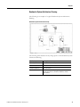
Secondary Treatment System Architecture Drawing
This is a typical Secondary Treatment System Architecture Drawing.
Secondary Treatment System Architecture Drawing
The following table describes the key design points of the Secondary
Treatment System Architecture Drawing.
Publication IASIMP-QS014C-EN-P - February 2013
Hardware
Description
ControlLogix Processor
Controls the Secondary Treatment System
1756 Series
Controls I/O
PowerFlex 700 Drive
Drives the pumps
EtherNet/IP
Establishes a communication path between the
ControlLogix Processor, PowerFlex 700 Drive, and the
plant network
19
Chapter 1
The WWWAT CD also contains System Architecture Drawings that are
intended only to support your application. Hardware modifications may be
required to fulfill your application needs. Consider these points when
designing the hardware for your application:
Each specific site must determine the 1756 Chassis I/O card
configuration based on the specific needs of the I/O devices adjacent to
that chassis.
The number of PowerFlex 700 Drives may change based on the number
of pumps in the Secondary Treatment System. Add more drives as
needed.
The Ethernet Switch has a limited number of ports. Select the
appropriate Stratix switch as required for the number of EtherNet/IP
devices in the system.
IP addresses and node numbers are unique to your application and you
must include them on this drawing.
20
Publication IASIMP-QS014C-EN-P - February 2013
Chapter 1
Solids Handling System Architecture Drawing
This is a typical Solids Handling System Architecture Drawing.
Solids Handling System Architecture Drawing
The following table describes the key design points of the Solids Handling
System Architecture Drawing.
Publication IASIMP-QS014C-EN-P - February 2013
Hardware
Description
ControlLogix Processor
Controls the Solids Handling System
1756 Series
Controls I/O
PowerView Plus
HMI
EtherNet/IP
Establishes a communication path between the
ControlLogix Processor, Control Panels, and the plant
network
21
Chapter 1
The WWWAT CD also contains System Architecture Drawings that are
intended only to support your application. Hardware modifications may be
required to fulfill your application needs. Consider these points when
designing the hardware for your application:
Each specific site must determine the 1756 Chassis I/O card
configuration based on the specific needs of the I/O devices adjacent to
that chassis.
The number of PowerFlex 700 Drives may change based on the number
of pumps in the Solids Handling System. Add more drives as needed.
The Ethernet Switch has a limited number of ports. Select the
appropriate Stratix switch as required for the number of EtherNet/IP
devices in the system.
IP addresses and node numbers are unique to your application and you
must include them on this drawing.
22
Publication IASIMP-QS014C-EN-P - February 2013
Chapter 1
Water Treatment Plant
Drawings
The Water Treatment Plant documentation package contains the following
system-level architectural drawings:
Raw Water Intake Pump Station System
Separation Station System
High Service Pump Station System
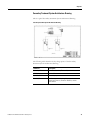
Raw Water Intake Pump Station System Architecture Drawing
This is a typical Run Water Intake Pump System Architecture Drawing.
Run Water Intake System Architecture Drawing
The following table describes the key design points of the Raw Water Intake
Pump Station System Architecture Drawing.
Publication IASIMP-QS014C-EN-P - February 2013
Hardware
Description
ControlLogix Processor
Controls the Raw Water Intake Pump Station System
1756 Series
Controls I/O
PowerFlex 700 Drive
Drives the pumps
EtherNet/IP
Establishes a communication path between the
ControlLogix Processor, PowerFlex 700 Drive, and the
plant network
23
Chapter 1
The WWWAT CD also contains System Architecture Drawings that are
intended only to support your application. Hardware modifications may be
required to fulfill your application needs. Consider these points when
designing the hardware for your application:
Each specific site must determine the 1756 Chassis I/O card
configuration based on the specific needs of the I/O devices adjacent to
that chassis.
The number of PowerFlex 700 Drives may change based on the number
of pumps in the Run Water Intake Pump Station System. Add more
drives as needed.
The Ethernet Switch has a limited number of ports. Select the
appropriate Stratix switch as required for the number of EtherNet/IP
devices in the system.
IP addresses and node numbers are unique to your application and you
must include them on this drawing.
24
Publication IASIMP-QS014C-EN-P - February 2013
Chapter 1
Separation Station System Architecture Drawing
This is a typical Separation Station System Architecture Drawing.
Separation System Architecture Drawing
The following table describes the key design points of the Separation Station
System Architecture Drawing.
Publication IASIMP-QS014C-EN-P - February 2013
Hardware
Description
ControlLogix Processor
Controls the Separation Station System
1756 Series
Controls I/O
PowerFlex 700 Drive
Drives the pumps
EtherNet/IP
Establishes a communication path between the
ControlLogix Processor, PowerFlex 700 Drive, and the
plant network
25
Chapter 1
The WWWAT CD also contains System Architecture Drawings that are
intended only to support your application. Hardware modifications may be
required to fulfill your application needs. Consider these points when
designing the hardware for your application:
Each specific site manager must determine the 1756 Chassis I/O card
configuration based on the specific needs of the I/O devices adjacent to
that chassis.
The number of PowerFlex 700 Drives may change based on the number
of pumps in the Separation Station System. Add more drives as needed.
The Ethernet Switch has a limited number of ports. Select the
appropriate Stratix switch as required for the number of EtherNet/IP
devices in the system.
IP addresses and node numbers are unique to your application and you
must include them on this drawing.
26
Publication IASIMP-QS014C-EN-P - February 2013
Chapter 1
High Service Pump Station System Architecture Drawing
This is a typical High Service Pump Station System Architecture Drawing.
High Service Pump Station System Architecture Drawing
The following table describes the key design points of the High Service Pump
Station System Architecture Drawing.
Publication IASIMP-QS014C-EN-P - February 2013
Hardware
Description
ControlLogix Processor
Controls the High Service Pump Station System
1756 Series
Controls I/O
PowerFlex 700 Drive
Drives the pumps
EtherNet/IP
Establishes a communication path between the
ControlLogix Processor, PowerFlex 700 Drive, and the
plant network
27
Chapter 1
The WWWAT CD also contains System Architecture Drawings that are
intended only to support your application. Hardware modifications may be
required to fulfill your application needs. Consider these points when
designing the hardware for your application:
Each specific site manager must determine the 1756 Chassis I/O card
configuration based on the specific needs of the I/O devices adjacent to
that chassis.
The number of PowerFlex 700 Drives may change based on the number
of pumps in the High Service Pump Station System. Add more drives as
needed.
The Ethernet Switch has a limited number of ports. Select the
appropriate Stratix switch as required for the number of EtherNet/IP
devices in the system.
IP addresses and node numbers are unique to your application and you
must include them on this drawing.
Pump Controller Station
Architecture Drawing
This is a typical Pump Controller Station Architecture Drawing.
Pump Controller Station Architecture Drawing
The following table describes the key design points of the Pump Controller
Station Architecture Drawing.
28
Hardware
Description
MicroLogix 1400
Controls the Pump Station
PanelView
Component C600
HMI
PowerFlex 4
Drives the Pumps
Publication IASIMP-QS014C-EN-P - February 2013
Chapter 1
Additional Resources
Publication IASIMP-QS014C-EN-P - February 2013
The WWWAT CD contains links to numerous websites where you can find
more information on the System Specification and Procurement phases of
your Water and Wastewater project. For more information on websites and
documentation that will help you plan and design your Water and Wastewater
project, see Appendix A.
29
Chapter 1
30
Publication IASIMP-QS014C-EN-P - February 2013
Chapter
2
Hardware Design
Introduction
This chapter contains valuable resources to help you design the necessary
Water and Wastewater hardware for your project.
Hardware Drawings
The WWWAT CD contains a System Architecture folder, which contains a
drawing package for each application. Each of these drawing packages consists
of a system overview and the basic electrical drawings for wiring the I/O. The
Lift Station package also includes device-level wiring information. These
examples can be used in the actual wiring of the field devices for the project.
Each Water and Wastewater project is unique. These hardware drawings
provide you with a starting point for the hardware engineering. You must
customize your project to meet your site requirements.
Water and Wastewater
Treatment Plant Hardware
Drawings
The Water and Wastewater Treatment Plant Hardware documentation package
contains the following system-level drawing packages:
Lift Station System
Dosing Pump Station System
Primary Treatment System
Headworks System
Secondary Treatment System
Solids Handling System
Chemical Feed System
Flushing System
The Lift Station and Dosing Pump Station drawings are included in this
section for reference. These are typical of the others- all can be found on the
WWWAT CD (Publication IASIMP-SP012). You can also go to the Rockwell
Automation Integrated Architecture Tools Website,
http://www.ab.com/go/iatools and download the drawings.
31Publication IASIMP-QS014C-EN-P - February 2013
31
Chapter 2
Lift Station Hardware Drawings
One of the System Architecture sub-folders on the WWWAT CD is the Lift
Station folder and it contains the following drawings:
Title Page and Sheet Index
Process Flow Diagram
Network Diagram
Panel I/O Layout Sheets
Device Wiring Schematics
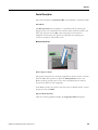
Title Page and Sheet Index
Lift Station Title Page and Sheet Index
32
Number
Title
Description
E-150
Title Page and
Sheet Index
This is the Table of Contents/Cover Sheet for the drawing
package. Modify this sheet as necessary to match the
contents of the drawing package for your application.
Publication IASIMP-QS014C-EN-P - February 2013
Chapter 2
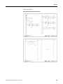
Process Flow Diagram
Lift Station System Process Flow Diagram
Number
Title
Description
E-160
System
Process Flow
Diagram
This diagram depicts a Lift Station consisting of two pumps
with particular I/O. Any changes to the number of pumps or
I/O for the Lift Station must be reflected on this diagram.
Network Diagram
Lift Station System Network Diagram
Publication IASIMP-QS014C-EN-P - February 2013
Number
Title
Description
E-170
Network
Diagram
For details, see page 12.
33
Chapter 2
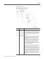
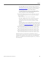
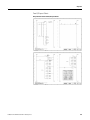
Panel I/O Layout Sheets
Lift Station System Panel I/O Layout Sheets
Number
Title
Description
E-180
Panel I/O Layout (Sheet 1 of 2)
E-181
Panel I/O Layout (Sheet 2 of 2)
Inputs and outputs to the controller are
shown on these diagrams. The format uses
three cards per sheet. Inputs to the card are
shown with the input device to the left of
the input card. Output devices are shown to
the right of the output card. For every
additional input or output card, new sheets
must be added.
These sheets contain one example of each
type of digital and analog I/O module
typically used in a Lift Station application.
Note: These modules are the input and
output points physically located on the L23
controller. Different I/O modules require
changes to these sheets. You should modify
these sheets to show the I/O specific to
your application. Use these sheets as a
template for applications even if the
specific I/O points vary.
34
Publication IASIMP-QS014C-EN-P - February 2013
Chapter 2
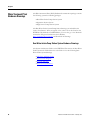
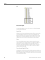
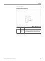
Device Wiring Schematics
Lift Station System Device Wiring Schematics
Number
Title
Description
E-182
Device Wiring
Schematics
This sheet provides power distribution and manual (hand)
selector switch wiring information.
For this application example, we recommend you use an
Allen-Bradley power supply to feed the L23 power, Stratix
Ethernet switch, and the PanelView Plus 600. Modify this
sheet to show any additional 24-volt devices required in the
design. During the project’s Hardware Engineering phase,
this 24 volt power supply must be accurately sized based on
the current requirements of the devices connected to it.
Publication IASIMP-QS014C-EN-P - February 2013
35
Chapter 2
Dosing Pump Hardware Drawings
One of the System Architecture sub-folders on the WWWAT CD is the
Dosing Pump folder and it contains the following drawings:
Title Page and Sheet Index
Process Flow Diagram
Network Diagram
Panel I/O Layout Sheets
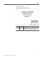
Title Page and Sheet Index
Dosing Pump Title Page and Sheet Index
36
Number
Title
Description
E-100
Title Page and
Sheet Index
This is the Table of Contents/Cover Sheet for the drawing
package. Modify this sheet as necessary to match the
contents of your application’s drawing package.
Publication IASIMP-QS014C-EN-P - February 2013
Chapter 2
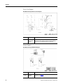
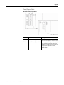
Process Flow Diagram
Dosing Pump System Process Flow Diagram
Number
Title
Description
E-110
System
Process Flow
Diagram
The Dosing Pump System Process Flow diagram depicts a
two pump alum addition process. You make any changes to
the number of pumps or I/O for this process on this drawing.
For example, if you require additional pumps in an
application, update this sheet with the appropriate pumps
and their associated I/O information.
The Dosing Pump System Process Flow diagram is very
helpful for a quick summary of the controls and the process
being controlled.
Publication IASIMP-QS014C-EN-P - February 2013
37
Chapter 2
Network Diagram
Dosing Pump System Network Diagram
38
Number
Title
Description
E-120
Network
Diagram
For details, see page 14.
Publication IASIMP-QS014C-EN-P - February 2013
Chapter 2
Panel I/O Layout Sheets
Dosing Pump System Panel I/O Layout Sheets
Number
Title
E-130
Panel I/O Layout These diagrams show the I/O to the controller. The format
uses three cards per sheet. This drawing depicts inputs to
(Sheet 1 of 3)
the card with the input device to the left of the Input card. It
Panel I/O Layout also shows output devices to the right of the output card.
You must add a new sheet for each additional input or
(Sheet 2 of 3)
output card.
Panel I/O Layout
This drawing package was designed with space reserved
(Sheet 3 of 3)
for all the Controller Chassis card slots. In this example
drawing package, slot 3 is empty. This empty slot is
represented on sheet E-131 with an empty area on the
sheet and the text "Spare." If you add a card to slot three,
you should show it in this spare area. If an additional
chassis is required, use this same format with space
reserved in the drawings for any empty slots of the chassis.
This provides a pre-determined location in the drawing
package for all the I/O modules.
E-131
E-132
Description
Include I/O information specific to your application on this
drawing. We expect you to modify these sheets to fit your
application. You use these sheets as a template for use
with many applications even though the specific I/O points
vary. These sheets include digital input and output modules
as well as analog input and output modules. The Dosing
Pump Panel I/O Layout Sheet contains one example of each
type of module that will typically be used in a lift station
application. Note, that these modules are 1756 style I/O
modules. Different I/O modules will require changes to
these sheets.
Publication IASIMP-QS014C-EN-P - February 2013
39
Chapter 2
Water Treatment Plant
Hardware Drawings
The Water Treatment Plant (WTP) Hardware documentation package contains
the following system-level drawing packages:
Raw Water Intake Pump Station System
Separation Station System
High Service Pump Station System
The Raw Water Intake System Pump Station drawings are included in this
section for reference. These are typical of the others- all can be found on the
WWWAT CD (Publication IASIMP-SP012). You can also go to the Rockwell
Automation Integrated Architecture Tools Website,
http://www.ab.com/go/iatools and download the drawings.
Raw Water Intake Pump Station System Hardware Drawings
The System Architecture folder on the WWWAT CD contains the Raw Water
Intake System sub-folder. Select this sub-folder to view the following Raw
Water Intake System drawings:
40
Title Page and Sheet Index
Process Flow Diagram
Network Diagram
Panel I/O Layout Sheets
Publication IASIMP-QS014C-EN-P - February 2013
Chapter 2
Title Page and Sheet Index
Raw Water Intake System Title Page and Sheet Index
Publication IASIMP-QS014C-EN-P - February 2013
Number
Title
Description
E-1100
Title Page and
Sheet Index
This is the Table of Contents/Cover Sheet for the drawing
package. Modify this sheet as necessary to match the
contents of the drawing package for your application.
41
Chapter 2
Process Flow Diagram
Raw Water Intake System Process Flow Diagram
Number
Title
Description
E-1110
System
Process Flow
Diagram
The flow diagram assumes a Raw Water Intake System with
particular I/O. Any changes to the I/O for the Raw Water
Intake System should be reflected on this diagram.
Network Diagram
Raw Water Intake System Network Diagram
42
Number
Title
Description
E-1120
Network
Diagram
For details, see page 23.
Publication IASIMP-QS014C-EN-P - February 2013
Chapter 2
Panel I/O Layout Sheets
Raw Water Intake System Panel I/O Layout Sheets
Number
Title
Description
E-1130
Panel I/O Layout
(Sheet 1 of 2)
E-1131
Panel I/O Layout
(Sheet 2 of 2)
This diagram depicts inputs and outputs to the controller.
This format uses three cards per sheet. Inputs to the card
are shown with the input device to the left of the input
card. Output devices are shown to the right of the output
card. You must add a new drawing sheet for every
additional input or output card.
This drawing package reserves space for all the "slots" of
a controller's chassis. If an additional chassis is required,
use this same format with space reserved in the drawings
for any empty slots of the chassis. This provides a
pre-determined location in the drawing package for all the
I/O modules.
I/O specific to an application are shown here and it is
expected that these sheets are heavily modified for each
application. These sheets provide a template for use for
many applications though even if the specific I/O points
vary. These sheets include digital input and output
modules as well as analog input and output modules. This
provides one example of each type of module that will
typically be used in a Raw Water Intake System
application.
Note: This drawing depicts 1756 style I/O modules. If you
use different I/O modules, you must also update these
sheets.
Publication IASIMP-QS014C-EN-P - February 2013
43
Chapter 2
Pump Controller Station
Hardware Drawings
One of the System Architecture sub-folders on the WWWAT CD is the Pump
Controller Station folder and it contains the following drawings:
Title Page and Sheet Index
Communications Diagram
Panel Layout Diagram
Power Layout Sheets
Panel I/O Layout Sheets
Title Page and Sheet Index
Pump Controller Station Title Page and Sheet Index
44
Number
Title
Description
Index
Title Page and
Sheet Index
This is the Table of Contents/Cover Sheet for the drawing
package. Modify this sheet as necessary to match the
contents of the drawing package for your application.
Publication IASIMP-QS014C-EN-P - February 2013
Chapter 2
Communications Diagram
Pump Controller Station Communications Diagram
Publication IASIMP-QS014C-EN-P - February 2013
Number
Title
Description
E-12
Pump Control
Communications
Diagram
Refer to Pump Controller Station Architecture Drawing on
page 28 for details.
45
Chapter 2
Panel Layout Diagram
Pump Controller Station Panel Layout Diagram
46
Number
Title
Description
13
Pump
Controller
Station Panel
Layout
Diagram
You can modify this as needed for your application
requirements.
Publication IASIMP-QS014C-EN-P - February 2013
Chapter 2
Power Layout Sheets
Pump Controller Station Power Layout Sheets
Publication IASIMP-QS014C-EN-P - February 2013
47
Chapter 2
48
Number
Title
Description
1, 3 and 5
Power Layout
Sheets
Pump Control Power Distribution, 480VAC Power, and
24VDC Power Drawings.
Publication IASIMP-QS014C-EN-P - February 2013
Chapter 2
Panel I/O Layout Sheets
Pump Controller Station Panel I/O Layout Sheets
Publication IASIMP-QS014C-EN-P - February 2013
49
Chapter 2
CAD Figures
50
Number
Title
Description
8-11
I/O Layout
Sheets
Pump Control Drive and PLC I/O Drawings.
The WWWAT CD contains both AutoCAD® and Adobe® PDF formatted
hardware template files that you can use when designing your application.
Template files are available in .dwg, .dxf and .pdf file format.
Publication IASIMP-QS014C-EN-P - February 2013
Chapter 2
Accessing the CAD Images from the WWWAT CD
The CAD files can be imported into your AutoCAD project for use in the
development of drawing packages for your water and wastewater application.
Download additional CAD files from the Rockwell Automation Configuration
and Selection Tools Website at
http://www.rockwellautomation.com/en/e-tools/.
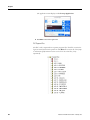
How to Access Additional CAD Figures from the Website
Use these steps to access the additional CAD figures from the Rockwell
Automation website.
1. Go to http://www.rockwellautomation.com/en/e-tools/.
2. On the Product Selection tab, type the catalog number of the part you
want, click on the product directory for additional information, or use
the Product Configuration Assistant.
Additional Resources
Publication IASIMP-QS014C-EN-P - February 2013
To assist you in the hardware design phase of your water or wastewater project,
the WWWAT CD contains links to numerous websites where you can find
useful and up-to-date information. For more information on websites and
documentation that will help you plan and design your Water and Wastewater
project, see Appendix A.
51
Chapter 2
Notes:
52
Publication IASIMP-QS014C-EN-P - February 2013
Chapter
3
Application Engineering
Additional Resources
To assist you in the hardware design phase of your Water and Wastewater
project, refer to the Water and Wastewater Accelerator Toolkit (WWWAT).
This toolkit resides on a CD and contains links to numerous websites that
contain useful and up-to-date information. Refer to the Preface for more
information about the WWWAT.
For more information on websites and documentation that will help you plan
and design your Water and Wastewater project, see Appendix A.
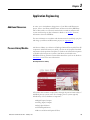
Process Library Module
The Process Library is a collection of RSLogix 5000 and FactoryTalk View SE
component Add-On-Instructions (AOIs), also known as faceplates. Rockwell
Automation developed these Faceplates to facilitate the efficient development
of flexible and robust process systems. This library is included on the
WWWAT CD along with the associated documentation (refer to the Preface’s
Introduction section for more information.
Selecting the Process Library
All systems share common components, although the precise functionality of
individual process systems varies. For example, process systems typically
include many of these hardware components:
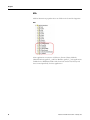
● Digital Inputs/Outputs
● Analog Inputs/Outputs
● Single Speed Motors
● Variable Speed Drives
● Motor and Solenoid Operated Valves
53Publication IASIMP-QS014C-EN-P - February 2013
53
Chapter 3
You must develop code to manage the interface between the Controller and
these devices. you must also create several of the following logical constructs
to merge this collection of hardware into a cohesive system:
● Alarms
● Interlocks
● Permissives
● Rule Base Inhibits
The Process Library includes RSLogix 5000 AOIs for performing each of
these tasks. In addition, the Library includes graphical objects for use in
building a Visual Interface to your Controller. The combination of code and
graphics ensures a visually and functionally consistent system.
The Process Library enables you to:
● Speed up development time and focus your energies on the custom
aspects of your application.
● Increase quality by reusing well-tested code to reduce the likelihood of
code bugs.
● Aids in producing well-structured code - in addition the standard
graphics increases the consistency of your HMI thus reducing the need
for operator training.
● Leverage scalability - build ever larger systems using the same reusable
modules.
54
Publication IASIMP-QS014C-EN-P - February 2013
Chapter 3
Using the Process Library Module
The Process Library is a collection of components that provide a large amount
of flexibility. You can choose to use any number of the modules and it does
not require you to code within a rigid structure. You also retain the flexibility
of a Logix System, while saving yourself the trouble of writing and maintaining
standard functionality.
The Process Library makes extensive use of AOIs, which are custom
instructions that a user designs and creates. Using AOIs, you can create new
commonly-used logic instruction sets, provide a common interface to this
logic, and provide instruction documentation.
AOIs are intended to be used to encapsulate commonly used functions or
device control. They are not intended to be a high-level hierarchical design
tool. Programs with routines are better suited to contain code for the area or
unit levels of your application. These are some benefits to using an AOI.
Reuse Code
AOIs promote consistency between projects by reusing commonly-used
control algorithms. For algorithms that will be used multiple times in the same
project or across multiple projects, it may make sense to incorporate that code
inside an AOI to make it modular and easier to reuse.
Provide an Easier to Understand Interface
AOIs enable you to design a more user friendly interface by:
● Placing complicated algorithms inside of an AOI and marking the
essential Parameters as visible or required.
● Reduce documentation development time through automatically
generated instruction help.
Publication IASIMP-QS014C-EN-P - February 2013
55
Chapter 3
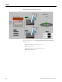
Intellectual Property Protection
An AOI enables you to insert Proprietary code inside it using source
protection to prevent unauthorized users from viewing or changing your code.
You can use AOIs across multiple projects. You can define the instructions,
the instructions can be provided by someone else, or they can be copied from
another project.
Once defined in a project, AOIs behave similarly to the built-in instructions
already available in the RSLogix 5000 software. They appear on the instruction
tool bar and in the instruction browser for easy access, just like built-in
RSLogix 5000 software instructions.
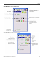
This is an example of AOIs in the instruction tool bar.
AOI Instruction Tool bar
56
Publication IASIMP-QS014C-EN-P - February 2013
Chapter 3
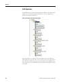
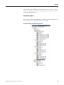
Using Add-On Instructions
This section lists the modules that exist in the Process Library and provides a
brief functional description for each of them. Refer to each module's
documentation for more detailed information. The Process Library section of
the WWWAT CD contains separate documentation files for each of the
modules. Refer to the Preface for more information about the WWWAT.
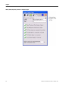
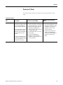
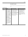
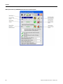
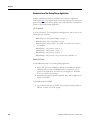
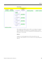
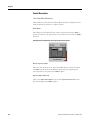
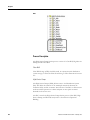
Alarm (P_Alarm)
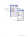
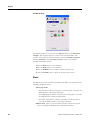
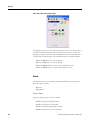
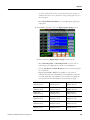
The following table describes the Alarm (P_Alarm) parameter and its usage.
Alarm (P_Alarm)
AOI
Description
Use This Instruction When
Alarm (P_Alarm) This instruction monitors an
input condition and when it has
been true for a specified time,
initiates an alarm. It also
monitors Alarm
Acknowledgement, Alarm
Reset, Alarm Inhibiting
/Disabling, and Alarm
Suppression (for FactoryTalk
Alarm and Events).
You want to develop your own AOIs
and have it generate alarms that are
compatible with the alarm setup for
the Process AOIs. Use the P_Alarm
instruction embedded within your
AOI.
You have a condition in your logic
(outside of any AOI) that you need to
generate an Alarm. Use the P_Alarm
instruction stand-alone within your
program logic.
Do Not Use This Instruction When
You have a discrete input signal from
a flow switch, pressure switch, level
switch, or other device and want to
display the device state, generate
alarms, or condition the alarm based
on time or gating signals. Use the
P_Alarm (Alarm) or P_DIn (Discrete
Input) AOI instead.
You need synchronized time stamping
features or other FactoryTalk Alarm
and Event features not supported by
P_Alarm. Instead, use the ALMD
built-in instruction.
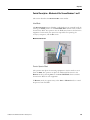
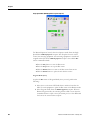
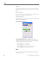
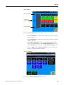
Once the system initiates an alarm, the alarm displays change color according
to their severity. A small bell appears in the upper right-hand corner of the
display to indicate that an alarm is active. If you must acknowledge the alarm,
this bell blinks.
Alarm AOI
Publication IASIMP-QS014C-EN-P - February 2013
57
Chapter 3
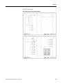
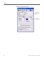
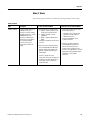
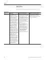
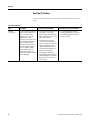
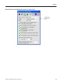
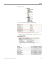
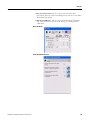
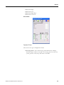
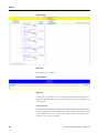
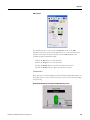
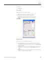
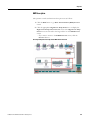
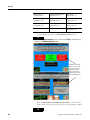
Analog Input basic Instruction (P_Aln)
The following table describes the Analog Input Basic Instruction (P_Aln)
parameter and its usage.
Analog Input Basic Instruction (P_Aln)
AOI
Description
Analog Input
(P_Aln)
This instruction monitors one
analog value, typically from an
analog input I/O module, and
provide alarms when the analog
value exceeds user-specified
limits (high and low).
The Analog Input Instruction
also provides capabilities for
linear scaling of an analog input
value from "raw" (input) units to
"engineering" (output) units,
and entry of a Substitute
Process Variable provides
handling of an out-of-range or
faulted input.
To keep the Instruction memory
and execution footprint small,
certain capabilities, used less
frequently, are reserved for the
Advanced Analog Input AOI.
58
Use This Instruction When
Do Not Use This Instruction When
You want to display a temperature,
flow, pressure, level, or another
signal from a field instrument on your
HMI.
You need any of the Scaling,
Alarming, or HMI features for an
Analog Input, or any Analog (quantity)
value.
You want Linear scaling from Raw to
Engineering Units.
You need High, Low, High-High,
Low-Low, and Out of Range alarms
(with dead band and delay per alarm).
You use an indicator graphic object
with label and engineering units.
You use a faceplate with mode
selection, alarm limit entry, and
maintenance capability for substitute
PV.
The analog input signal works with
another instruction. For example, the
Speed Feedback for a variable speed
drive is completely handled by the
P_VSD Instruction. It is not necessary
to use the P_AIn instruction first.
Wire or map the input directly to
P_VSD.
You only need to display a number on
a screen and do not need any of the
scaling or alarming features. (Just
use a numeric display field.)
You need advanced capabilities such
as square root extraction (for
example, orifice flow meters),
rate-of-change alarming or limiting,
or alarming for deviation from a
reference value. Use the P_AInAdv
(Advanced Analog Input) Instruction
instead.
You have the dual sensors for one
process variable (such as dual pH
meters) and need to select one or the
other sensor (or their average). Use
the P_AInDual (Dual Analog Input)
Instruction instead.
Publication IASIMP-QS014C-EN-P - February 2013
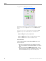
Chapter 3
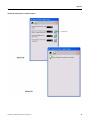
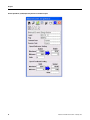
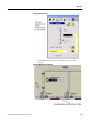
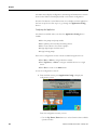
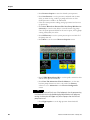
Analog Input (P_Aln) Process Variable Faceplate
Publication IASIMP-QS014C-EN-P - February 2013
59
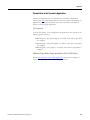
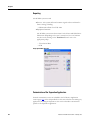
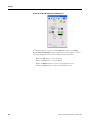
Chapter 3
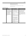
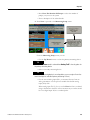
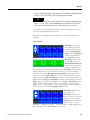
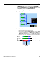
Analog Input (P_Aln) Engineering Tab Faceplate
60
Publication IASIMP-QS014C-EN-P - February 2013
Chapter 3
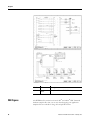
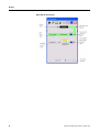
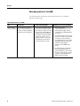
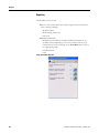
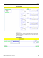
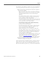
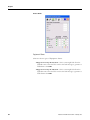
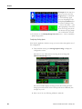
Digital Input Instruction (P_Dln)
The following table describes the Digital Input Instruction (P_Dln)
parameter and its usage.
Digital Input Instruction (P_Dln)
AOI
Description
Digital Input (P_Dln) This AOI receives and
processes a single discrete
condition (bit or PV), typically
for a channel of a discrete
input card. It can be used with
any discrete (BOOL) signal. The
P_Dln AOI includes the
capability to generate a
discrete input alarm, such as
from a low level switch, high
vibration switch, or flow
switch.·
Use This Instruction When
You want to display the state of a
process temperature, level, flow,
proximity, pressure, or other switch.
You need any of these signal
processing or alarming features for
a discrete input or any discrete (bit)
value.
You require debounce of a Discrete
Input signal.
You want the system to activate an
alarm when the Discrete Input is not
in a target state for some period of
time.
Do Not Use This Instruction When
You need only to show or not show
the state of a bit on an HMI display.
Use basic display objects (text,
multi-state indicators) with
appropriate animation instead.
You need only to generate an alarm
from some condition you already
have in your code. Use the P_Alarm
AOI or the ALMD built-in instruction
instead.
You want the system to enable an
alarm when a gating condition is
true for some period of time.
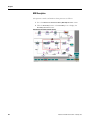
You want the system to display the
switch state with configurable text
on an HMI object with operator
Faceplate call-up.
You need Maintenance to be able to
provide a substitute value when the
device has failed.
Publication IASIMP-QS014C-EN-P - February 2013
61
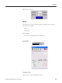
Chapter 3
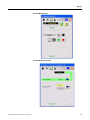
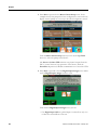
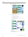
Digital Input (P_Din) Faceplate
62
Publication IASIMP-QS014C-EN-P - February 2013
Chapter 3
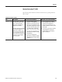
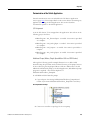
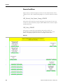
Interlock Instruction (P_Intlk)
The following table describes the Interlock Instruction (P_Intlk) parameter
and its usage.
Interlock Instruction (P_Intlk)
AOI
Description
Interlock (P_Intlk) This AOI collects ("sums up")
the Interlock conditions which
stop a running (energized,
open) piece of equipment or
prevent it from starting.
Interlocks are always evaluated
to de-energize equipment. For
"permissive" conditions, such
as those that must be made to
start the equipment but which
are ignored once the equipment
is running, use the P_Perm
(Permissives) AOI.
Publication IASIMP-QS014C-EN-P - February 2013
Use This Instruction When
You have multiple interlock
conditions or cascaded interlock
conditions (an interlock hierarchy)
which stop some equipment (motor,
valve, drive) or keep it from starting.
Link the P_Intlk Status bits to the
Inp_IntlkOK and Inp_NBIntlkOK
inputs of the motor, valve, or drive.
You need a first-out indication of
which interlock condition shut down
the equipment.
Do Not Use This Instruction When
You have conditions that prevent
starting equipment, but which are
ignored once the equipment is
running. Those are permissive, not
interlock conditions. Use the P_Perm
AOI instead.
You have only one interlock condition
for the equipment. Connect the
condition directly to the interlock
input on the device.
You want configurable text
descriptions of shutdown conditions
and other features of the P_Intlk
Faceplates.
63
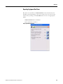
Chapter 3
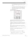
Interlock (P_Intlk) Faceplate
64
Publication IASIMP-QS014C-EN-P - February 2013
Chapter 3
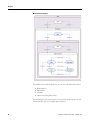
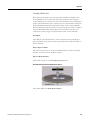
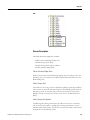
Mode (P_Mode)
The following table describes the Mode (P_Mode) parameter and its usage.
Mode (P_Mode)
AOI
Description
Mode (P_Mode)
This AOI provides selection of
the Mode (owner) of an
instruction or control strategy.
The Mode instruction is usually
embedded within other
instructions to extend their
functionality. It is possible to
use a stand-alone Mode
instruction to enhance a
program where modes are
wanted.
Use This Instruction When
Creating an AOI for a device which:
Requires separate acquisition by
an operator and Program logic
Supports Override or Hand
capabilities
Needs a separate Maintenance
Mode
Embed the P_Mode instruction within
your AOI.
Creating a Control Strategy and you
want standard arbitration between
operator and Program modes (and
perhaps Override, Maintenance, or
Hand modes).
Use the P_Mode instruction
stand-alone within your strategy and
condition Commands and Actions in
the strategy on the P_Mode AOI
mode Status bits.
Publication IASIMP-QS014C-EN-P - February 2013
Do Not Use This Instruction When
Creating an AOI which does not do
anything differently for:
operators versus Program logic
Override or Hand conditions
Maintenance users.
You do not need Modes or the
P_Mode instruction.
Creating a complex strategy for
shared equipment (Shared Use
Common Resource) which has
complex rules for arbitration and
allocation of the equipment. You need
rule-based sharing logic beyond the
capabilities of the P_Mode
instruction.
65
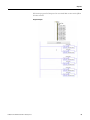
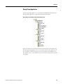
Chapter 3
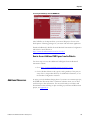
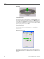
Mode Explanation Diagram
The modes have the following priority (also shown in the illustration above):
1.
2.
3.
4.
Hand (highest)
Maintenance
Override
Operator and Program (lowest)
The AOI still processes and retains the lesser priority mode requests, but the
resultant mode is that of the highest priority request.
66
Publication IASIMP-QS014C-EN-P - February 2013
Chapter 3
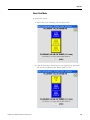
Selecting Modes
This table shows how to request, verify, and release a mode. It also shows the
trigger input cycle.
Mode
Request (Input)
Acquired (Output
Release (Input)
Hand
Inp_Hand=1(level)
Sts_Hand=1
Inp_Hand=0 (level)
Maintenance
MCmd_Acq=1(edge) Sts_Maint=1
MCmdRel=1(edge)
Override
Inp_Ovrd=1(level)
Sts_Ovrd=1
Inp_Ovrd=0(level)
Operator
OCmd_AcqLock=1
Sts_Oper=1
OCmd_UnLock=1
Program
See Program Mode
See Program Mode
See Program Mode
Program Mode
The Program Command functionality depends on the configuration for
clearing Program Commands (Cfg_PCmdClear).
Publication IASIMP-QS014C-EN-P - February 2013
Mode
Option
Command
Description
Program
Cfg_PCmdClear=1 PCmd_Acq=1 (edge)
PCmd_Rel=1 (edge)
PCmd_Lock=1 (edge)
PCmd_Unlock=1 (edge)
Request Program Mode
Release Program Mode
Lock Program Mode
Unlock Program Mode
Cfg_PCmdClear=0 PCmd_Acq=1 (level)
PCmd_Acq=0 (level)
PCmd_Lock=1 (level)
PCmd_Lock=0 (level)
Request Program Mode
Release Program Mode
Lock Program Mode
Unlock Program Mode
67
Chapter 3
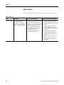
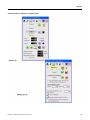
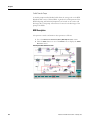
Motor (P_Motor)
The following table describes the Motor (P_Motor) parameter and its usage.
Motor (P_Motor)
AOI
Description
Motor (P_Motor)
The P_Motor (single speed
motor) object controls a
non-reversing, single speed
motor in a variety of modes and
monitors for fault conditions.
Use This Instruction When
You want to control a single-speed
(running or stopped) motor. The
motor can use a full voltage starter
(FVNR), a soft starter or other motor
protective equipment. However, it
might provide run feedback. The
P_Motor AOI provides Faceplates
and graphic symbols for the
operator display, control and
appropriate modes/alarms.
Do Not Use This Instruction When
You want to control a two-speed
(fast/slow/stopped) motor. Use the
P_Motor2Spd (two speed motor) AOI
instead.
You want to control a reversing
(forward/stopped/reverse) motor.
Use the P_MotorRev Reverse Motor)
AOI instead.
You want to control a motor with
continuously-varying speed. Use the
P_VSD (Variable Speed Drive) AOI
instead.
You want to control a motor that is
part of a valve actuator. Use the
P_ValveMO (Motor-Operated Valve)
AOI instead.
68
Publication IASIMP-QS014C-EN-P - February 2013
Chapter 3
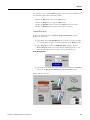
Motor (P_Motor) Operator Tab Process Variable Faceplate
Motor (P_Motor) Maintenance Tab Process Variable Faceplate
Publication IASIMP-QS014C-EN-P - February 2013
69
Chapter 3
Motor (P_Motor) Engineering Tab Process Variable Faceplate
70
Publication IASIMP-QS014C-EN-P - February 2013
Chapter 3
Permissive (P_Perm)
The following table describes the Permissive (P_Perm) parameter and its
usage.
Permissive (P_Perm)
AOI
Description
Permissive (P_Perm) This AOI collects ("sums up")
the Permissive conditions which
allow a piece of equipment to
start (run, energize, open, etc.).
Permissive conditions generally
must only be true to start the
equipment. Once the equipment
is running, Permissives are
ignored.
Use the P_Intlk (Interlocks) AOI
for collecting conditions which
stop running equipment as well
as prevent it from starting.
Publication IASIMP-QS014C-EN-P - February 2013
Use This Instruction When
You have multiple or cascaded
Permissive conditions which prevent
some equipment (motor, valve, and
drive) from starting, but which are
ignored once the equipment is
running. Link the P_Perm Status bits
to the Inp_PermOK and
Inp_NBPermOK inputs of the motor,
valve, or drive.
You want configurable text
descriptions of the Permissive
conditions and other features of the
P_Perm Faceplates.
Do Not Use This Instruction
When
You have conditions that shut
down running equipment as well
as prevent it from starting. These
are interlock, not Permissive
conditions. Use the P_Intlk
Instruction instead.
You have only one Permissive
condition for the equipment connect the condition directly to
the permissive input on the
device.
71
Chapter 3
Reset (P_Reset)
The following table describes the Reset (P_Reset) parameter and its usage.
Reset (P_Reset)
AOI
Description
Reset (P_Reset)
This AOI provides a central
point at which to reset
equipment faults and latched
alarms for a control strategy.
The P_Reset accepts an
Operator Reset Command, a
Program Reset Command, and a
Reset Input. These commands
are initiated from a button
input, higher-level P_Reset AOI
(from a containing control
strategy, say a Unit Reset sent
to a P_Reset at Equipment
Module scope), or from any
other source. The Reset AOI
also includes a "Reset
Required" input for collecting
the "Ready to Reset" outputs of
the various instructions it resets
and providing a "ready to reset"
("reset required") status which
can illuminate a button or make
an HMI reset button visible. The
Reset AOI includes a timer
function which causes its
output to be held on for at least
a minimum time. This allows
the reset signal to be sent via
physical output cards to field
devices that may required it
(e.g., motor drives) and gives
time for the cleared status from
the device to propagate back to
an Interlock or Permissive
inputs to the system.
72
Use This Instruction When
You want a common reset point
("Master Reset") for alarms and
fault conditions for a control
strategy, process unit, process
cell or equipment group, process
area or plant section, or even a
small site. Tie the output of the
P_Reset instruction to the
Inp_Reset input of the equipment
to be reset.
Do Not Use This Instruction When
You want to reset a single piece of
equipment (valve, motor). Use the
Operator or Program Reset Command
directly on the equipment.
You want a cascading reset
strategy, where there is a
P_Reset instruction for a small
equipment scope such as a
strategy which incorporates
resets from wider scope (unit,
cell, area, site) resets. Tie the
output of the higher-level
P_Reset instruction to the
Inp_Reset input of the
lower-level P_Reset instruction.
Publication IASIMP-QS014C-EN-P - February 2013
Chapter 3
Reset Inhibit (P_ResetInh)
The following table describes the Reset Inhibit (P_ResetInh) parameter and its
usage.
Reset Inhibit (P_ResetInh)
AOI
Description
Reset Inhibit
(P_ResetInh)
This AOI prevents damage to a
large motor through repeated
starts. The high starting
current for a large motor
causes considerable heating.
Because the thermal mass of
a large motor is much smaller
relative to its horsepower and
starting current compared to
smaller motors, repeated
starts (or start attempts) over
a short time will overheat the
motor windings, potentially
damaging the motor
permanently. The Restart
Inhibit AOI provides a
rule-based state model for
restarts and is NOT intended
to model or monitor the motor
heating. It cannot replace
sensor-based motor
monitoring systems. It can,
however, be a simple solution
to avoid overstressing a motor
without the cost (money or
Controller resources) of more
extensive modeling and
monitoring.
Publication IASIMP-QS014C-EN-P - February 2013
Use This Instruction When
You have a large motor or other piece
of equipment where repeated
start/stop cycles or failures to start
may damage the equipment.
The state model of the P_ResInh
instruction is appropriate for limiting
the restarts of the equipment ("Three
Starts" rule, hot/cold model, etc.).
You don't have the sensors or
equipment for more advanced motor
monitoring or modeling.
Do Not Use This Instruction When
You have more advanced motor
monitoring equipment or motor
heating models available. Use the
advanced equipment to provide a
start permissive instead.
You have a small motor that can
repeatedly start and stop without
damage, or a simple thermal cutout
provided with the motor is sufficient
to protect it.
73
Chapter 3
Run Time (P_RunTime)
The following table describes the Run Time (P_RunTime) parameter and its
usage.
Run Time (P_RunTime)
AOI
Description
Runtime
(P_RunTime)
This AOI is used to accumulate
the total run time and count of
starts for a motor or other
equipment. It is a software
implementation of the
mechanical "hour meter" that is
often mounted in the door of a
motor control center (MCC)
bucket to show total motor run
time. The time and number of
starts are variables used by
maintenance personnel to
determine when to perform
maintenance activities on motor
or other equipment.
74
Use This Instruction When
You want the functionality of a run
time meter or start counter
without having to add hardware
devices for these functions to your
Motor Control Center.
Do Not Use This Instruction When
You have advanced software for
monitoring equipment run time that
only needs the equipment running
status as its input.
You need the total run time,
current run time, maximum run
time or start count information for
a piece of equipment on the
operator display and you do not
have monitoring software that
provides the information.
Your equipment monitoring
software expects the Controller to
provide equipment run time and
starts values rather than just a
Running status.
Publication IASIMP-QS014C-EN-P - February 2013
Chapter 3
Run Time (P_RunTime) Process Variable Faceplates
Publication IASIMP-QS014C-EN-P - February 2013
75
Chapter 3
Motor Operated Valve (P_ValveMO)
The following table describes the Motor Operated Valve (P_ValveMO)
parameter and its usage.
Motor Operated Valve (P_ValveMO)
AOI
Description
Variable Speed
Drive (P_ValveMo)
This AOI operates (open and
close) a motor-operated valve in
a variety of modes (see below),
monitoring for fault conditions.
Use This Instruction When
To use a motor-operated valve or
other valve that requires separate
open and close outputs. This valve
may use limit switch feedback for
the ends of travel. The valve may
also require an output to trigger a
"valve stop" function, such as
breaking a seal-in circuit on the
valve operator to stop travel or
switch the direction of travel.
Do Not Use This Instruction When
You need to operate a
single-solenoid spring-return valve
(fail closed or fail open). Use the
P_ValveSO Solenoid-Operated Valve
AOI instead.
You need to operate a multi-solenoid
valve such as a Mix-Proof Valve that
has positions (such as CIP) other
than "opened" and "closed." You will
need specific Mix-Proof Valve logic.
(A Mix-Proof Valve Add-On
Instruction may be added in the
future.)
You need to monitor a valve that is
primarily operated by hand. The
valve could support a "trip" output to
drive it to a "safe" position. Use the
P_ValveHO Hand-Operated Valve
Add-On Instruction instead.
76
Publication IASIMP-QS014C-EN-P - February 2013
Chapter 3
Motor Operated Valve (P_ValveMO) Operator Tab Process Variable Faceplate
Publication IASIMP-QS014C-EN-P - February 2013
77
Chapter 3
Motor Operated Valve (P_ValveMO) Maintenance Tab Process Variable Faceplate
78
Publication IASIMP-QS014C-EN-P - February 2013
Chapter 3
Motor Operated Valve (P_ValveMO) Engineering Tab Process Variable Faceplate
Publication IASIMP-QS014C-EN-P - February 2013
79
Chapter 3
Variable Speed Drive (P_VSD)
The following table describes the Variable Speed Drive (P_VSD) parameter
and its usage.
Variable Speed Drive (P_VSD)
AOI
Description
Variable Speed
Drive (P_VSD)
This AOI is used to operate one
variable speed motor using a
Drive (AC variable frequency or
DC) in a variety of Modes,
monitoring for fault conditions.
Use This Instruction When
Do Not Use This Instruction When
You need to operate a motor
connected to a variable-speed drive.
The drive can be an AC (variable
frequency) or DC drive, and can be
connected via an I/O or control
network (intelligent drive) or via
hardwired analog and discrete I/O.
This instruction is designed to work
with all currently-available and many
legacy Allen-Bradley drives, including
Bulletin 1336, Bulletin 1395,
PowerFlex 4 / 40 / 70 / 700 / 7000
and PowerFlex DC. This instruction
will also work with drives and other
variable-speed motor control
products via discrete I/O for the
start/stop/running signals and analog
I/O for the speed reference and speed
feedback signals.
80
You need to operate a single-speed
motor (running / stopped only). Use
the P_Motor Instruction instead.
You need to operate a two-speed
motor (fast / slow / stopped only).
Use the P_Motor2Spd Instruction
instead.
You need to operate a simple
reversing motor (forward, reverse,
stopped only). Use the P_MotorRev
Instruction instead.
You need to operate a motor with
multiple discrete speeds. You will
need specific logic for this motor.
The P_VSD Instruction is designed
for motors with continuously
variable (analog) speed, not multiple
discrete speed selection.
Publication IASIMP-QS014C-EN-P - February 2013
Chapter 3
Variable Speed Drive (P_VSD) Process Variable Faceplate
Publication IASIMP-QS014C-EN-P - February 2013
81
Chapter 3
Variable Speed Drive (P_VSD) Engineering Tab Process Variable Faceplate
82
Publication IASIMP-QS014C-EN-P - February 2013
Chapter 3
WWWAT CD Applications
The WWWAT CD contains sample applications that you can use to begin your
Water and Wastewater project.
There are three major application groupings on the WWWAT CD - Water
Treatment Development Tools, Wastewater Treatment Development Tools,
and Pump Controller Station. Refer to Pump Controller Station on page 234.
Water/Wastewater Development Tools
Press the Water or Wastewater Development Tools to locate these
applications.
Water/Wastewater Treatment Application Framework
All Water/Wastewater Treatment applications on the WWWAT CD share a
common framework. This section examines that framework.
The WWWAT CD (Phase 4) contains the following Water/Wastewater
Treatment applications:
● Lift Station System
● Dosing Pump Station System
● Headworks System
● Secondary Treatment System
● Solids Handling System
● Chemical Feed System
● Flushing System
● Raw Water Intake Pump Station System
● Separation Station System
● High Service Pump Station System
Publication IASIMP-QS014C-EN-P - February 2013
83
Chapter 3
The System Controller organization includes:
1. Task - Main Task, for example
2. Program - Pumps, for example
3. Routine - A01_DiscreteInputs for example
The components of this organization correspond to areas of the application.
The task component is application-wide. The Program component should be
used with the application’s functional area and each routine is dedicated to a
specific action within this functional area. For example, the entire Lift Station
System is contained within a Task. Pump control is contained within a
program and functionality within a pump, such as pump control versus pump
alarming is separated into different routines.
Lift Station System Application Organization
All programs contain a routine (Main) which is used to call all the other
routines in the task. A Job Status Report (JSR) must be included in the Main
routine for every routine in the program. For example, the following depicts a
84
Publication IASIMP-QS014C-EN-P - February 2013
Chapter 3
Lift Station program for Pumps and its associated Main routine with a JSR to
all other routines:
Program Example
Publication IASIMP-QS014C-EN-P - February 2013
85
Chapter 3
Inputs and Outputs
The philosophy for real-world inputs and outputs are that they are "mapped"
to tags in the Controller. Each I/O point occurs once in the Controller on the
rung where it is mapped. For example, consider this rung:
Inputs and Outputs
In the Lift Station application, the Wet Well Low Level Sensor has been
electrically connected to the 10th input on the card in slot one of the Local
Rack.
The mapping of physical I/O to internal bits is good programming practice
for the following reasons:
● If the electrical design changes, you only have to make one change in the
program.
● Keeping all this inputs and outputs together keeps your application
clean and consistent.
This mapping should be done on the same rung as the object that uses the
input for the following reasons:
● When troubleshooting an object, you can immediately see the state of
the I/O associated with it and check that the correct I/O is mapped to
the correct location.
● It provides a simple understanding of which I/O applies to a particular
object.
86
Publication IASIMP-QS014C-EN-P - February 2013
Chapter 3
The following example depicts the P_Motor object. All I/O associated with
this motor is mapped on the rung with the motor object.
P_Motor Object
Publication IASIMP-QS014C-EN-P - February 2013
87
Chapter 3
AOIs
Add-On Instructions populate their own folder in the Controller Organizer.
AOIs
These applications contain two AOI classes, Process Library Modules
(identified with the prefix P_) and User Modules. (prefix U_). The applications
included in the WWWAT include AOIs from both the Process Library and
those created specifically for these applications.
88
Publication IASIMP-QS014C-EN-P - February 2013
Chapter 3
Using the Process Modules
The Process Modules are included in this Toolkit and can be imported into
your application as required. These modules are distributed as XML (.L5X)
and must be imported into your application as AOIs. To import an XML file
into your application:
1. Click File > Import Component > Add-On Instruction.
Select/Import AOIs
Once you import an AOI, the system lists it in the Controller Organizer’s AOI
folder. The Process Library Module code may be viewed but not edited.
User Modules
The applications in this toolkit also contain user modules. These modules can
be identified by the prefix U_ and have been written exclusively for the
WWWAT and its associated applications. Use these AOIs as written or
customize them as required.
Publication IASIMP-QS014C-EN-P - February 2013
89
Chapter 3
Water and Wastewater
Treatment Plant
Applications
The Water and Wastewater Treatment Plant (WWTP) documentation package
contains the following applications:
● Lift Station System
● Dosing Pump Station System
● Headworks System
● Secondary Treatment System
● Solids Handling System
Lift Station System Application
The WWWAT CD contains a Lift Station system application. This application
is written assuming up to six pumps transfer the Lift Station building well
contents to the Raw Sewage wet well at the Wastewater Treatment Plant. You
can also modify the application use in a pumping application where pump
control is based on the level of a wet well.
The Water and Wastewater sections of the WWWAT contain the Lift Station
system application because of its general applicability. Its Controller
organization is shown below:
90
Publication IASIMP-QS014C-EN-P - February 2013
Chapter 3
Lift Station System Application Controller Organization
The functionality for each program and routine is:
● Main Program handles Lift Station-wide inputs and outputs.
Main routine calls the other routines in this program and includes a
Wall Clock AOI that calculates the day of the week.It also includes a
Pump Inputs simulation bit that you can use when testing the
application.
A01_DiscreteInput maps inputs that are relevant throughout the Lift
Station.
A02_AnalogInput maps analog inputs that are relevant throughout
the Lift Station.
A03_AnalogInputs maps inputs that are relevant throughout the Lift
Station.
A04_AnalogOutputs maps outputs that are relevant throughout the
Lift Station.
● Pump System determines how many pumps to run and which pumps to
start. This is a supervisor of the pumps.
Main routine calls the other routines in this program.
A01_StartOrder determines the order in which to start the pumps.
Publication IASIMP-QS014C-EN-P - February 2013
91
Chapter 3
A02_Control calculates the pump demand (the number of pumps to
start).
● Pumps handle only pump control. Start and Stop commands are issued
to these programs and they handle unit level control of the pump
motors.
Main routine calls the other routines in this program.
A0x_Pumpn_Alarms handles inputs and alarms relating to a specific
pump.
A0x_Pumpn_Control handles pump control - permissives and
interlocks for the motor as well as the control of the motor itself are
handled here.
92
Publication IASIMP-QS014C-EN-P - February 2013
Chapter 3
Control Description
Normally, the wet well pumps transfer the Lift Station well contents when the
well level rises above the programmed high water level in the well.
Alternatively, floats in the wet well control the pumps, in case of a
Programmable Logic Controller (PLC) fault or level transmitter malfunction.
This allows the pumps to turn on via a hard-wired circuit if the water level is
too high.
Hand Mode
Place the pumps in Hand control:
1. Select Hand mode on the Drive Speed selector switch at the Feed Pump
control panel.
2. Select Hand mode on the Pump Start selector switch at the Feed Pump
control panel.
3. In Hand position, press the button station located on the control panel
to start/stop a pump.
Remote Operator Mode
Place the pumps in Remote Operator control:
1. Select Remote on the MCC for pumps 1 and 2. Verify that circuit
breakers and disconnects are turned on.
2. Select Operator mode on the Lift Station Pump No.x Faceplate screen
for each of the pumps 1 and 2.
3. Verify that the pump status is in service on the Lift Station Pump No.x
Faceplate screen with no faults.
Human Machine Interface (HMI) Control
Go to the Lift Station screen from the HMI screen:
1. Click the Lift Station 1 button. The system displays the Lift Station
screen.
Publication IASIMP-QS014C-EN-P - February 2013
93
Chapter 3
Selecting the Lift Station 1 Button on the HMI Screen
2. Click the Wet Well Level Faceplate. The system displays the Process
Library Faceplate for the analog module that is monitoring the Wet Well
Level.
Lift Station Screen
94
Publication IASIMP-QS014C-EN-P - February 2013
Chapter 3
Lift Station Level Faceplate
The Lift Station screen depicts the Wet Well Level with a water
animation.
Lift Station Wet Well Level Animation
Publication IASIMP-QS014C-EN-P - February 2013
95
Chapter 3
Lift Station Wet Well Level Animation
Pump Faceplates
For each pump in the Lift Station, there are a Pump, Motor, and Digital Input
Faceplate.
Lift Station Pump Faceplate
96
Publication IASIMP-QS014C-EN-P - February 2013
Chapter 3
Lift Station Motor Faceplate
Lift Station Digital Input Faceplate
Publication IASIMP-QS014C-EN-P - February 2013
97
Chapter 3
Pump Setpoints
The Pump Setpoint screen provides you with information about when each
pump should start and stop.
1. Click the Pump Setpoints button that appears on the Lift Station screen.
The system displays the Pump Setpoint screen.
Lift Station Pump Setpoint Screen
2. Use the Start or Stop fields to adjust the setpoint for when each pump
starts and stops. The setpoints are based on the Wet Well Level.
For example, in the illustration above, the lead pump starts pumping
when the well level goes above 1.0 feet. The pump stops when the level
drops below 0.5 feet. This results in a dead band of 0.5 feet. The lag
pump operates similarly, except that it starts at 2.0 feet and stops at 1.5
feet. You can easily adjust all of these values on this single screen.
3. Adjust the Lead and Lag pumps using the Operator Settings switches in
the lower right side of this screen.
98
Publication IASIMP-QS014C-EN-P - February 2013
Chapter 3
a. Click the appropriate radio button to assign a pump as Lead or Lag.
The screen contains Lead and Lag radio buttons for Pump 1 and
Pump 2.
For example, in the illustration below, pump 1 is assigned as the lag
pump and pump 2 is assigned as the lead pump. Pump 2 will start
when the water level reaches the start level for the lead pump and
stop when the water level drops to the stop level. You can change
these assignments at any time.
Lift Station Pump Setpoint Screen
The sequence of pumps is shown below these switches. The sequence
displayed will reflect the sequence currently active in the Controller. If any
pump fails to start, the next pump in the sequence will start.
For example, if the lead pump's disconnect is pulled and does not start, the
next pump in the sequence will run. The above illustration is showing only two
pumps. The sample code in the Controller provides routines for up to six
pumps.
There is a development screen provided that can be used as a starter for
additional pumps. It can be opened on the HMI by selecting the Test 6 Pumps
button from the overview screen.
Wet Well pumps are not interlocked with the main plant well. If the main well
is in an alarm state, the Lift Station pumps will start in Auto.
Run Pumps Manually
Use the following steps to run the pumps manually from the HMI:
1. While in Maintenance or Operator mode, navigate to the Lift Station
screen.
2. Click on the desired pump and then click on the Play button.
Publication IASIMP-QS014C-EN-P - February 2013
99
Chapter 3
3. Click on the Stop button to stop the pump from the Control screen. In
manual mode, the pump will continue to run regardless of a low Wet
Well level.
Run Pumps Manually
Place Pumps in Remote Program
Place the pumps in Remote Program control.
1. Select Remote on the MCC for pumps 1 and 2.
2. Verify that the circuit breakers and disconnects are turned on.
3. Make sure on the Lift Station Pump N.ox Faceplate, for pump numbers
1 and 2 are in the unlocked Operator mode.
4. Verify that the pump status is in service on the Lift Station Pump N.ox
Faceplate screen with no faults.
5. Verify that the correct pump rotation sequence has been selected and
the start/stop pump set points are set to the correct level.
100
Publication IASIMP-QS014C-EN-P - February 2013
Chapter 3
Alarms
The Lift Station generates these two types of alarms.
● Process Alarms
● Equipment Alarms
Process Alarms
These are the six different types of Process Alarms:
● Low Level (the wet well is low)
● High Level (the wet well is high)
● Low Low Level (the wet well is extremely low)
● High High Level (the wet well is extremely high/or is overflowing)
● High Level Float
● Low Level Float
Equipment Alarms
These are the four different types of Equipment Alarms.
● Pump Permissive - Inhibit Restart
● Pump Interlock - Motor Overload, Motor High Temperature, or Low
Water Cutoff
● Start-Stop Pump Failure - Check the MCC selector switch and local
disconnect
● I/O Fault
Use the Lift Station Level Faceplate to configure the analog Process Alarms
changing condition. Users with the correct security level can also inhibit both
alarms.
Publication IASIMP-QS014C-EN-P - February 2013
101
Chapter 3
Lift Station Level Faceplate
Customization
The example programs included on the WWWAT CD provide you with a start
to the application development. Typically, many customizations and
adjustments have to be made to the application to make it operational for a
particular project.
Customization is a vital part of the software development. This section
outlines some of the basic tasks that must be done for this customization and
other steps may be necessary. The important point to remember is that these
example applications only serve as a start. It is the responsibility of the
application engineer to assess the requirements of the project, take ownership
of the application, and drive it to completion.
Some general customization concepts will be discussed in this section. Though
you may not be interested in the Lift Station application, it is an important
section to read because the customization information contained in this
section applies to other areas as well.
I/O Assignment
As mentioned earlier in this document, I/O is mapped at one place in the
application for each I/O point. As part of customizing the example Lift
102
Publication IASIMP-QS014C-EN-P - February 2013
Chapter 3
Station application, be sure to check all the locations for I/O that is mapped
including the following:
● MainProgram - A01_DiscreteInput - rungs 0 - 4
● MainProgram - A02_AnalogInput - rungs 0 - 3
● MainProgram - A03_DiscreteOutputs - as needed
● MainProgram - A04_AnalogOutputs - as needed - this routine is not
used in the example
For Pump I/O, each pump has its own routines in the Pumps program. The
routines are numbered sequentially, A01, A02, etc. For I/O mapping go to the
following rungs:
● Pumps - A0x_Pumpn_Alarms - rungs 0 - 4
● Pumps - A0x_Pumpn_Control - rungs 3 - 5
Where: x = sequential routine number, n = pump number
This is not intended to be a complete list of the I/O assignments necessary. It
is only intended to point out some required rungs that must be customized for
a particular application. As an important step in the software development
process, care should be taken to properly assign I/O to all the necessary places
in the software. Many I/O points for a specific application may not be
anticipated by this example application. In these situations, additional software
must be developed to account for these points.
Motor Permissives and Interlocks
The sample Lift Station application provides places for additional permissives
and interlocks to be added to the program. Keep the following points in mind:
● Permissives allow or prevent a motor from starting. If a permissive is
not true, the motor will not start when it receives a start command. But
once the motor is started, it will continue to run on a loss of a
permissive.
● Interlocks allow or prevent a motor from continuously running. If an
interlock is not true, the motor will not run when it receives a start
command. Once the motor is started, it will stop on a loss of an
interlock.
● To include additional permissives for a pump motor to start, add
contacts to rung 3 of A02_Control in Pump 1 or Pump 2.
● Each permissive input is mapped on a branch in this rung. All these
permissives are inputs to the Process Library AOI that is located on the
last branch of the rung. All permissives must be true to allow the pump
to start. If there is an input that is normally closed, use an XIO
instruction on the branch of the rung to properly map it into this AOI.
Publication IASIMP-QS014C-EN-P - February 2013
103
Chapter 3
Motor Permissives and Interlocks
Resets
Fault and Alarm resets in the application are accomplished through a P_Reset
block from the Process Library. This reset object distributes the Reset
command to all the Process Library AOIs that may require a reset.
Care must be taken in deciding how to distribute the reset commands. This
must be planned before the customizations that follow can be completed.
Considerations include questions such as:
● What devices will reset when a particular button is pressed?
● How are devices to be grouped they are reset at the same time with the
same reset button?
● Do some devices overlap into more than one Reset group?
For example, in the Lift Station application provided in the WWWAT, the reset
is distributed to all the pumps. Rung 2 of each Pump Control routine has a
104
Publication IASIMP-QS014C-EN-P - February 2013
Chapter 3
branch for the Reset button. To remove a pump from this Reset group, tie a
different Reset button to this branch.
In general, there are three important customizations that are required with this
object:
● Assigning all the Reset Required bits to the P_Reset object
● Assigning all the devices, such as buttons that can initiate a reset to the
P_Reset object
● Properly distributing the Reset command to all objects that will use its
reset.
Lift Station Pump Control Rung 2
Assigning the Device That Initiates the Reset
Assigning the device that initiates the reset is also done on the rung with the
P_Reset object. Add branches here for all devices that can initiate a Reset
command to this P_Reset object. These devices may include commands from
the HMI, hard-wired reset buttons or other operator interfaces that provide a
Reset command.
Assigning the Reset Required
Assigning the Reset Required bits is done on the rung with the P_Reset object.
All Reset Required bits from all objects that will receive the reset command
must provide a Reset Required bit to this reset. Add branches to this rung for
each device that will fall within the group for this P_Reset. The illustration
below demonstrates these reset required bits and the branch required.
Publication IASIMP-QS014C-EN-P - February 2013
105
Chapter 3
Lift Station Reset Command
Distributing the Reset Command
Once a reset is initiated and the P_Reset sends its Reset command, all devices
that are to receive this reset must be mapped to the proper Reset bit. This is
done in a distributed manner. Each device that is to receive the reset will have
a branch on the rung mapping this Reset command to its Reset input. See the
Lift Station Reset Command with a Digital Input Object illustration for an
example with a Digital Input object. The idea is the same for all other objects
that accept a reset. Each rung for an object that requires a reset will require a
branch like the one shown below.
106
Publication IASIMP-QS014C-EN-P - February 2013
Chapter 3
Lift Station Reset Command with a Digital Input Object
Mode Selection
Routines for Pump 1 and Pump 2 include a rung that handles mode operation
of the routine. This rung is shown in the Lift Station Pump 1/Pump 2 Mode
Selection Rung illustration.
Publication IASIMP-QS014C-EN-P - February 2013
107
Chapter 3
Lift Station Pump 1/Pump 2 Mode Selection Rung
By latching on the Program Acquire Command, the application will default to
Program Control of the application in the absence of a request to switch to
Maintenance or Hand modes. When one of these modes is requested, the
program will switch to these modes. However, when the request is no longer
active, the application reverts to Program Control.
Unlatching the Program Command Clear bit determines the style of mode
control. With this bit set to zero, a level type of control is required for mode
selection. This means that to remain in a particular mode, the request for that
mode must be maintained. For example, to select Program mode, the Program
request command bit must remain 1. Latching this Program Command Clear bit
would select an Edge type of control where setting the Program bit once on a
one-shot will trigger the transition to Program mode. Once the transition
occurs, the command bit is turned off. The command to change the mode is
called a command acquisition bit. Within the application, modes change by
manipulating these PCmd_Acq or OCmd_Acq bits. PCmd is the request for
program control or automatic, OCmd is operator control.
In general, the change of mode with the Program Command Clear bit latched is
sensitive to the change of state of the mode acquire bit whereas with the
Program Command Clear bit unlatched, the state is determined by the state of
the mode acquire bit itself.
This application is using the program command clear bit unlatched as the style
of mode selection - this is the maintained style of mode control. If you wish to
change this type of control to the Edge style, an understanding of the method
of mode selection within the Process Library is required. These paragraphs
have touched on this topic, but more information can be found within the
Process Library documentation. Refer to the manual for the Mode object for
more detailed information.
108
Publication IASIMP-QS014C-EN-P - February 2013
Chapter 3
Adding or Removing Pumps
The Controller application provides routines for up to six pumps. The HMI
application is written for two pumps although a test screen is provided to serve
as a start or seed for adding additional pumps to the HMI. Both applications
can be adjusted to suit your process but this requires an understanding of the
software and careful customization. This section describes some of the details
that must be tended to as pumps are added or removed.
To adjust the number of pumps in the Controller, first add or delete routines
as necessary to have one alarm and one control routine for each pump. Note
that these routines are numbered sequentially with A0x where x is the
sequential. You may number the pumps or name them as required for your
application. You may choose to name a pump PumpWest instead of Pump1
for example.
Lift Station Pump Controller Routines
All these routines should be contained in the Pumps program and every
routine must have a JSR instruction in the Main routine.
Publication IASIMP-QS014C-EN-P - February 2013
109
Chapter 3
Lift Station Pump JSR Instructions
In A02_Control of the Pump System Program, configure the number of
pumps total by setting Pump.Demand.CFG_PosTotal to equal the number of
installed pumps.
110
Publication IASIMP-QS014C-EN-P - February 2013
Chapter 3
Lift Station Pump 1/Pump 2 Mod
After making these changes, map all the I/O associated with the additional
pumps. Refer to the I/O Assignment section of this document.
Changes to the HMI application can be summarized by explaining that adding
pumps to the HMI simply requires duplicating existing animation on the
screen and assigning the proper pump tags to each of the HMI components.
Be sure to not only add additional animations for the pumps, but also for the
discrete inputs located under each pump and for pump sequence control
indicating lead and lag.
Below are examples of all the components that should be duplicated for this
application. Note that the descriptions change for each. For example, Pump 1
to Pump 3 and the backing tags must be updated to the appropriate tag in the
Controller. Some of these animations are on the main Lift Station overview
screen and some are on the Pump Setpoints screen.
Lift Station Duplicated Component Examples
Publication IASIMP-QS014C-EN-P - February 2013
111
Chapter 3
A basic test screen for 6 pumps is provided to give you a start on creating
additional pumps. This can be accessed via the Test 6 Pumps button on the
Lift Station screen.
This Test 6 Pumps button is not intended to remain in a working application
and should be removed once it is determined how many pumps the
application will have. The Lift Station Test 6 Pumps Example illustration
depicts a test screen with six pumps. This serves only as a start from which to
customize your application.
Lift Station Test 6 Pumps Example
112
Publication IASIMP-QS014C-EN-P - February 2013
Chapter 3
Dosing Pumps Application
The Dosing Pumps application is provided on the WWWAT CD. This is the
Dosing Pump application’s organization within the Controller.
Dosing Pumps System Application Controller Organization
This task resides in a Controller located in the main facility of the plant using
the Dosing Pump application. It is not intended to be the only application in
the Controller. A ControlLogix processor is specified for this application for
that specific reason. It is assumed the processor will be running other systems
of the plant.
Publication IASIMP-QS014C-EN-P - February 2013
113
Chapter 3
The organization of this application is similar to that of the Lift Station.
Specifically, the functionality for each program and routine is:
● Main Program handles general Dosing Pump application’s functionality,
including:
Main routine calls the other routines in this program and includes a
Wall Clock AOI that calculates the day of the week. It also includes a
Pump Inputs simulation bit that you can use when testing the
application.
A01_DiscreteInput maps inputs that are relevant throughout the
Dosing Pumps.
A02_AnalogInput maps analog inputs that are relevant throughout
the Dosing Pumps.
A03_AnalogInputs maps inputs that are relevant throughout the
Dosing Pumps.
● PSys determines how many pumps to run and which pumps to start.
This is a supervisor of the pumps.
Main routine calls the other routines in this program.
A01_Control contains the code for the pump decisions and metering.
● Feed Pump 1 and Pump 2 handle only pump control. Start and Stop
commands are issued to these programs and they handle unit level
control of the pump motors.
Main routine calls the other routines in this program
A01_Alarms handles inputs and alarms relating to a specific pump
A02_Control handles pump control - permissives and interlocks for
the motor as well as the motor control itself are handled here.
Add-On Instructions are used extensively in this application. There is a
collection of Process Library AOIs and a collection of other AOIs developed
specifically for this application. Process Library AOIs can be identified by a
prefix "P_" in their name. The other AOIs have a prefix of "U_" as shown in
the AOI illustration.
114
Publication IASIMP-QS014C-EN-P - February 2013
Chapter 3
AOIs
Control Description
Phosphorus concentrations in the final effluent are limited by the National
Pollutant Discharge Elimination System (NPDES) Permit, meaning that the
plant is required to implement treatment steps. Feeding Alum to the
wastewater increases the amount of sludge generated which will result in larger
quantities sludge in the secondary clarifiers.
The Alum is pumped from the two storage tanks by two metering pumps
(numbers 1, and 2). These pumps are paced by the plant flow rate.
WARNING
Alum is a potentially dangerous substance and must be handled
with care.
From the overview screen, click the Alum button or the Alum Storage Tank
icon to display the Dosing Pump Application screen.
Publication IASIMP-QS014C-EN-P - February 2013
115
Chapter 3
Selecting the Alum Button
Dosing Pump Alum Feed Screen
The lower left of the Alum Feed screen shows the status of the Alum storage.
The Alum storage tanks are equipped with ultrasonic level sensors to measure
the gallons stored Alum in each tank. The tank volume and pump status are
displayed on the Alum Feed Overview screen. Selecting the Alum Storage
116
Publication IASIMP-QS014C-EN-P - February 2013
Chapter 3
Level display opens the Analog Input Faceplate for the Alum level. This is a
standard Process Library Faceplate.
To obtain pump status and control, click either pump icon. Clicking a pump
opens the Process Library Faceplate for VFDs. The variable speed Alum Feed
Pumps may be operated in either Hand or Remote mode as selected by a
Remote-Off-Hand selector switch at the associated control panel.
Hand Mode
Use the following steps to place the Feed Pumps in Hand Control mode.
1. Select Hand mode on the Drive Speed selector switch at the Feed Pump
control panel.
2. Select Hand mode on the Pump Start selector switch at the Feed Pump
control panel. In Hand position, the operator starts and stops the pump
using the appropriate button station located on the control panel. To
adjust chemical dosing use the Motor Speed potentiometer at the Feed
Pump Control Panel.
Remote Operator Mode
Use the following steps to place the Feed Pumps in Remote Operator control
mode:
1. Select Remote mode on the Drive Speed selector switch at the Feed
Pump control panel.
2. Select Remote mode on the Pump Start selector switch at the Feed
Pump control panel.
3. Select Operator mode from the HMI.
4. The pump is started and stopped remotely from the HMI screen. A
faceplate is displayed by clicking on the Feed Pump icon.
5. To start the pump, press Play and to stop the pump, press Stop.
6. To modulate the Feed Pump rate, either click in the Operator Setpoint
box and type in a value between 0 and 100 percent to change the speed
value in the Speed Setpoint box.
7. To remove the Feed Pump from service, click Disable, and to place the
unit back in service, click Enable.
Remote Program Mode
Use the following steps to place the Feed Pumps in Remote Program Control
mode.
1. Select Remote mode on the Drive Speed selector switch at the Feed
Pump control panel.
Publication IASIMP-QS014C-EN-P - February 2013
117
Chapter 3
2. Select Remote mode on the Pump Start selector switch at the Feed
Pump Control Panel.
3. Select the Program mode from the HMI.
The pump runs and the output (feed rate) is controlled by the flow pacing
signal and the dosage (adjustable at the HMI from 0- X ppm), entered by the
operator. Transfer between the Controller operator and Program modes is
smooth. The pump output in gallons per hour (feed rate) and stroke speed
setpoint is calculated. The Program Logic Controller (PLC) will output the
speed signal to the pump based on the appropriate flow pacing signal.
Alum Control Setpoints
118
Publication IASIMP-QS014C-EN-P - February 2013
Chapter 3
Alarms
The Supervisory Control and Data Acquisition (SCADA) system generates
these two types of alarms.
● Process
● Equipment
Process Alarms
There are the four types of Process Alarms.
● Low Level (the Alum storage tank is low)
● High Level (the Alum storage tank is high)
● Low Low Level (the Alum storage tank is extremely low)
● High High Level (the Alum storage tank is extremely High)
Using the Analog Signal faceplate, all four process alarms can be configured
for changing condition. Users with the correct security level can also inhibit all
alarms.
Equipment Alarms
These are the two types of Equipment Alarms.
● Alum Fault - Check the Feed Pump control panel for system or over
current faults.
● Start-Stop Pump Failure - Check the local disconnect and pump status.
Process Alarms
Publication IASIMP-QS014C-EN-P - February 2013
119
Chapter 3
Customization of the Dosing Pumps Application
General customization notes are included in the Lift Station Application
section (page 102) of this chapter. Refer to this section before customizing any
application, including the Dosing Pumps. This section describes customization
specific to the Dosing Pumps application.
I/O Assignment
As in the Lift Station, I/O is mapped into this application. This is done in the
following project locations:
● MainProgram - A01_DiscreteInput - rungs 0 - 4
● MainProgram - A02_AnalogInput - rung 0
● MainProgram - A03_Outputs - as needed - this routine is not used in
the example
● FeedPump1 - A01_Alarms - rungs 0 - 4
● FeedPump1 - A02_Control - rungs 3 - 5
● FeedPump2 - A01_Alarms - rungs 0 - 4
● FeedPump2 - A02_Control - rung 5 for the motor related I/O
Additional Pumps
To add additional pumps to the Dosing Pump application:
1. Adjust A01_Control in FeedPSys to include for the additional pumps.
Modifying A01_Control in FeedPSys requires customization that is
specific to the application. You must use your judgment to determine
how to incorporate these changes.
2. Add additional pump programs as required. These will be duplicates of
FeedP1 and FeedP2.
To add additional Feed Pumps:
1. Copy and paste the existing FeedP1 or P2 program. Both programs are
identical, so either one can be copied.
120
Publication IASIMP-QS014C-EN-P - February 2013
Chapter 3
Feed Pump Program Folders
2. Create new controller-scoped tags for the third pump.
Controller Scoped Tags
3. Locate the program scoped tags for the new Pump 3 program.
4. Define the Alias for Device (and the other associated tags) as this new
Controller-scoped tag.
Alias Device Definition Screen
5. Configure and alias for all I/O for the new pump. The Required Pump
I/O illustration depicts the subset of the I/O required.
Required Pump I/O
Publication IASIMP-QS014C-EN-P - February 2013
121
Chapter 3
Be sure to alias all the I/O to the new points for the additional pump. Be
certain that all inputs and outputs are aliased to the correct location.
6. Verify the new routines verify and ensure that they contain no errors.
The most commonly overlooked issues will be reconciling all the tags
used in the routine. The ladder diagram itself will likely verify since this
is a duplicate of another function routine.
Pump I/O Verification Screen
122
Publication IASIMP-QS014C-EN-P - February 2013
Chapter 3
Additional Flow Pacing
To include additional flow pacing for other pumps, add rungs to routine
A01_Control in program FeedPSys. Each pump with flow pacing requires a
U_FlowPacing AOI on its own rung. Add additional rungs below the existing
Flow Pacing rungs as shown in the Adding Rungs To The FeedPSys Program
AO1_Control illustration.
Adding Rungs to the FeedPSys Program A01_Control
Publication IASIMP-QS014C-EN-P - February 2013
123
Chapter 3
Headworks Application
The Headworks application is provided on the WWWAT CD. Refer to the
Headworks System Application Controller Organization illustration to view
the application’s organization within the Controller.
Headworks System Application Controller Organization
This task should reside in a Controller in the main facility of the plant where
the Headworks application is present and it is not intended to be the only
application in the Controller. A ControlLogix processor is specified for this
application for that specific reason. It is assumed the processor will be running
other systems of the plant.
124
Publication IASIMP-QS014C-EN-P - February 2013
Chapter 3
The organization of this application is similar to that of the Lift Station.
Specifically, the functionality for each program and routine is:
● Main Program handles general Headworks application and functionality,
including:
Main routine calls the other routines in this program and includes a
Wall Clock AOI that calculates the day of the week.It also includes a
Pump Inputs simulation bit that you can use when testing the
application.
A01_MiscDiscreteInput includes a template to map inputs that are
relevant throughout the Headworks system. This routine is provided
as a Function Block Diagram.
A02_MiscAnalogInput includes a template to map analog inputs that
are relevant throughout the Headworks system. This routine is
provided as a Function Block Diagram.
A03_MiscOutputs includes a template to map outputs that are
relevant throughout the Headworks system.
● BarScreen01 controls the motor, manages cycle times, and Flow
Channel Differential levels for the Bar screen 1 system, including:
Main routine calls the other routines in this program.
A01_BarScreen01_LDR contains the code to monitor and control
the Bar Screen 01 motor and reset alarms, interlocks, and faults
associated with the motor. This routine is provided as a Ladder
Diagram.
A02_BarScreen01_FBD contains the Single Speed Motor,
Permissives and Interlock AOIs that monitor and control the Bar
Screen 01 motor. This routine is provided as a Function Block
Diagram.
A03_BarScreen01_Auto contains the Cycle Timer (including the
U_RepeatCycTmr AOI) and High Differential Alarm code. This
routine is provided as a Ladder Diagram.
A04_DiffLevel contains the Analog Input AOI that monitors the
differential pressure levels of Preliminary Treatment Flow Channel
No 1. This routine is provided as a Function Block Diagram.
● BarScreen02 Controls the motor and manages cycle times and flow
channel differential levels for the Bar Screen 2 system as described for
BarScreen01 above.
● GritTank01 Controls the motor and manages cycle times for the
GritTank01 system, including:
Main routine calls the other routines in this program.
A01_GritTankDrive_LDR contains the code to monitor and control
the Bar Screen 01 motor and reset alarms, interlocks and faults
associated with the motor. This routine is provided as a Ladder
Diagram.
Publication IASIMP-QS014C-EN-P - February 2013
125
Chapter 3
A02_GritTankDrive_FBD contains the Single Speed Motor,
Permissives and Interlock AOIs that monitor and control the Grit
Tank 01 motor. This routine is provided as a Function Block
Diagram.
A03_GritTankDrive_Auto contains the Cycle Timer (including the
U_RepeatCycTmr AOI) code. This routine is provided as a Ladder
Diagram.
A04_GritTankFlow contains the Analog Input AOI and U_FlowTot
AOI that aggregates the Grit Tank 01 flow. This routine is provided
as a Function Block Diagram.
● Wet well monitors Wet well level and generates alarms, including:
Main routine calls the other routines in this program.
A01_Wellwell contains the code to monitor Wet Well level and
generates alarms utilizing the Analog (P_AIn) and Discrete (P_Din)
Input AOIs. This routine is provided as a Function Block Diagram.
AOIs are used extensively in this application. There is a collection of Process
Library AOIs and a collection of other AOIs developed specifically for this
application. Process Library AOIs can be identified by a prefix "P_" in their
name. The other AOIs have a prefix of "U_" as shown in the AOI illustration.
AOIs
Process Description
The Headworks treatment consists of Screening, Influent Flow Measurement,
and Grit Removal. From the inlet well, the wastewater enters one or two
preliminary treatment flow channels. Each flow channel consists of an
126
Publication IASIMP-QS014C-EN-P - February 2013
Chapter 3
Inclined Bar screen with a mechanical raking device to remove debris from the
raw wastewater. The Mechanical Bar screens cycle periodically to rake debris
from the bar rack and deposit the screenings on a belt conveyor. This conveyor
runs during the screening cycle and moves the screenings to the Screenings
Compactor which empties into the grit and screen hopper for subsequent
disposal.
HMI Description
The operator controls and monitors these processes as follows:
1. Go to the Overview screen.
2. Click the Headworks button or the Headworks icon to display the
Headworks Application screen.
Selecting the Headworks Button
Publication IASIMP-QS014C-EN-P - February 2013
127
Chapter 3
Headworks/Primary Treatment Overview Screen
The status information on the Headworks/Primary Treatment Overview
screen includes:
● Mechanical Bar screen Numbers.1 and 2
● Grit Tank Drive No. 1
● Channel Numbers 1 and 2, Differential Level
● Channel Number 1 Flow
128
Publication IASIMP-QS014C-EN-P - February 2013
Chapter 3
Control Description - Mechanical Bar Screen Numbers 1 and 2
This section describes the Mechanical Bar screen modes.
Hand Mode
The Mechanical Bar screens Number 1 and Number 2 are operated locally by
selecting the Hand position on the Hand-Off-Auto selector switch, which is
located at the MCC. The operator uses the BAR screen buttons located at the
equipment. In this mode, the operator is responsible for operating the
conveyor, compactor, and the Bar screen.
Mechanical Bar Screen
Remote Operator Mode
The operator must place the screening equipment in the this mode to use it
from the HMI. The operator can place the Mechanical Bar screen in the
Remote mode by selecting Auto on the Auto-Off-Hand selector switches
located at the MCC for each equipment.
In Remote mode, the operator may select Auto or Manual mode to control
the process from the HMI.
Publication IASIMP-QS014C-EN-P - February 2013
129
Chapter 3
Operator Mode (Manual)
Click the screening equipment to display the Single Speed Motor Faceplate
screen.
Single Speed Motor Faceplate Screen (HMI Template)
For Manual Operator Control, select the Operator mode from the HMI
equipment Faceplate. The Faceplate shown is used to control the screening
equipment. The screening equipment is started and stopped remotely from the
HMI screen. The available Bar screen commands include:
● Press the Play button to start the Bar screen.
● Press the Stop button to stop the Bar screen.
● Click the Disable button to remove the Bar screen from service.
● Click the Enable button to place the unit back in service.
Program Mode (Auto)
To place the Bar screen in Program Mode (Auto) control, perform the
following:
1. Select Auto on the Auto-Off-Hand selector switches located at the
MCC for each equipment to place the Bar screen in the Remote mode.
2. Select Program mode from the HMI Faceplate template. When in
Remote Program mode, the screening will be called to start when the
accumulated time is equal to the Cycle Timer pre-set or the differential
level across the screen reaches setpoint.
130
Publication IASIMP-QS014C-EN-P - February 2013
Chapter 3
Bar Screen Cycle Timer
The following sequence will occur when the screening system is run in Auto:
1. The system commands the Mechanical Bar screen to start.
2. The Mechanical Bar screen will run for 2 minutes before being called to
stop.
3. The operator can access the Control Setpoints by selecting the
Setpoints button on the Headworks/Primary Treatment Overview
screen.
Setpoints Button Location
Grit Removal
This section describes the Grit Removal, Hand, Remote Operator, and
Program modes.
Hand Mode - Grit Tank Drive (GTD) No. 1
Operate the drive in the Local mode by selecting Hand on the Hand-Off-Auto
selector switch located at the MCC. The operator uses the buttons located at
the tank to start or stop each drive.
Publication IASIMP-QS014C-EN-P - February 2013
131
Chapter 3
Grit Tank Drive
Remote Operator Mode
The operator must place the Grit Tank Drive in the Remote Operator mode to
use it from the HMI. The Grit Tank Drive is placed in the Remote mode by
selecting Auto on the Auto-Off-Hand selector switches located at the MCC for
each equipment. In the Remote mode, the operator may select Auto or Manual
mode to control the process from the HMI.
Operator Mode (Manual)
Once the operator clicks on the GTD equipment, the system displays a
Faceplate screen.
HMI Equipment Faceplate Screen
The operator uses this Faceplate screen to control the GTD equipment. For
Manual Operator Control, select the Operator mode from the HMI equipment
Faceplate.
132
Publication IASIMP-QS014C-EN-P - February 2013
Chapter 3
The operator starts/stops the GTD equipment remotely from the HMI screen.
The available GTD screen commands include:
● Press the Play button to start the GTD screen.
● Press the Stop button to stop the GTD screen.
● Click the Disable button to remove the GTD screen from service.
● Click the Enable button to place the unit back in service.
Program Mode (Auto)
To place the GTD equipment in Remote Program Mode (Auto) control,
perform the following:
1. Select Auto on the Auto-Off-Hand selector switches located at the MCC
for each equipment to place the GTD equipment in the Remote mode.
2. Select Program mode from the HMI Faceplate template. When in
Remote Program mode, the system calls the GTD equipment to start
when the accumulated time is equal to the Cycle Timer pre-set.
Bar Screen Cycle Timer
3. The operator can access the Control Setpoints by selecting the Setpoints
button on the Headworks/Primary Treatment Overview screen.
Setpoints Button Location
Publication IASIMP-QS014C-EN-P - February 2013
133
Chapter 3
Alarms
The Supervisory Control and Data Acquisition (SCADA) system generates
these two types of alarms.
● Process
● Equipment
Process Alarms
There are the six types of Process Alarms.
● Channel No. 1 Differential Level High Alarm
● Channel No. 2 Differential Level High Alarm
● Wet well Level High Alarm
● Wet well Level Low Alarm
● Wet well Float High High Alarm
● Wet well Float High Alarm
● Wet well Float Low Alarm
Process Alarms
134
Publication IASIMP-QS014C-EN-P - February 2013
Chapter 3
Equipment Alarms
These are the two types of Equipment Alarms.
● Start/Stop Faults - If the system calls the Mechanical Bar screen and it is
not running after 5 seconds, he system generates a Start/Stop Fail Alarm
and displays it at the HMI.
● Start/Stop Faults - If the system calls the GTD to start and is not
running after 5 seconds, the system generates a Start/Stop Fail Alarm
and displays it at the HMI.
Reporting Equipment Run Times
Run times are recoded for the Mechanical Bar screen mechanism by the
SCADA system. Depending on the user's security level, the total run time
maybe reset by clicking on the Total Reset button next to the appropriate
pump.
● Mechanical Bar Screen Numbers 1 and 2
● Grit Tank Drive Number 1
Single Speed Motor Run Time
Publication IASIMP-QS014C-EN-P - February 2013
135
Chapter 3
Customization of the Headworks Application
General customization notes are included in the Lift Station Application
section (page 102) of this chapter. Refer to this section before customizing any
application, including the Headworks. This section describes customization
specific to the Headworks application.
I/O Assignment
As in the Lift Station, I/O is mapped into this application. This is done in the
following project locations:
● MainProgram - A01_DiscreteInput - as needed - this routine is provided
as a template.
● MainProgram - A02_AnalogInput - as needed - this routine is provided
as a template.
● MainProgram - A03_Outputs - as needed - this routine is provided as a
template.
Additional Pumps/Motors (Single Speed Motor AOIs in a FBD Routine)
See the Customization of the Solids Application section for an example of
how to add Single Speed Motor AOIs in a FBD routine.
136
Publication IASIMP-QS014C-EN-P - February 2013
Chapter 3
Secondary Application
The WWWAT CD contains the Secondary application. Refer to the Secondary
System Application Controller Organization illustration to view the
application’s organization within the Controller.
Secondary System Application Controller Organization
This task resides in a Controller in the main facility of the plant where the
Secondary application is present and it is not intended to be the only
application in the Controller. A ControlLogix processor is specified for this
application for that specific reason. It is assumed the processor will be running
other systems of the plant.
Publication IASIMP-QS014C-EN-P - February 2013
137
Chapter 3
The organization of this application is similar to that of the Lift Station.
Specifically, the functionality for each program and routine is:
● Main Program handles general Secondary application and functionality,
including:
Main routine calls the other routines in this program and includes a
Wall Clock AOI that calculates the day of the week.It also includes a
Pump Inputs simulation bit that you can use when testing the
application.
A01_MiscDiscreteInput includes a template to map inputs that are
relevant throughout the Secondary system. This routine is provided
as a Function Block Diagram.
A02_MiscAnalogInput includes a template to map analog inputs that
are relevant throughout the Secondary system. This routine is
provided as a Function Block Diagram.
A03_MiscOutputs includes a template to map outputs that are
relevant throughout the Secondary system. This routine is provided
as a Function Block Diagram.
● SecTank01_Drive Controls the motor for the Secondary Clarifier Tank
1 system, including:
Main routine calls the other routines in this program.
A01_Drive _LDR contains the code to monitor and control the
Secondary Tank 01 motor and Reset Alarms, Interlocks, and Faults
associated with the motor. This routine is provided as a Ladder
Diagram.
A02_Drive_FBD contains the Single Speed Motor, Permissives, and
Interlock AOIs that monitor and control the Secondary Tank 01
motor. (See the Using Add-On Instructions section above for more
information.) This routine is provided as a Function Block Diagram.
● SecTank 02_Drive Controls the motor for the Secondary Clarifier Tank
2 system as described for the Secondary Clarifier Tank 1.
● Aeration Blower Controls the motor for the Blower system, including:
Main routine calls the other routines in this program.
A01_Blower _LDR contains the code to monitor and control the
Blower motor and Reset Alarms, Interlocks, and Faults associated
with the motor. This routine is provided as a Ladder Diagram.
A02_Blower_FBD contains the Single Speed Motor, Permissives and
Interlock AOIs that monitor and control the Blower motor (See the
Using Add-On Instructions section above for more information).
This routine is provided as a Function Block Diagram.
● SecTank01_RAS Pump Controls the Variable Speed Drive for the RAS
Pump, including:
Main routine calls the other routines in this program.
A01_Pump_LDR contains the code to monitor and control the VFD
for the RAS Pump, Reset Alarms, Interlocks, and Faults associated
with the pump. This routine is provided as a Ladder Diagram.
138
Publication IASIMP-QS014C-EN-P - February 2013
Chapter 3
A02_Pump_FBD contains the Variable Speed Drive, Permissives,
and Interlock AOIs that monitor and control the RAS Pump (See the
Using Add-On Instructions section above for more information).
This routine is provided as a Function Block Diagram.
A04_PumpDischargeFlow contains the Analog Input AOI and
U_FlowTot AOI that totalizes the RAS pump discharge flow. This
routine is provided as a Function Block Diagram.
● AerationTk01_Mixer01 Controls the motor and manages cycle times
and flow channel differential levels for the Aeration Tank 1 Mixer 1
system, including:
Main routine calls the other routines in this program.
A01_Mixer _LDR contains the code to monitor and control the
Aeration Tank 1 Mixer 1 Reset Alarms, Interlocks, and Faults
associated with the motor. This routine is provided as a Ladder
Diagram.
A02_Mixer_FBD contains the Single Speed Motor, Permissives, and
Interlock AOIs that monitor and control the Aeration Tank 1 Mixer
1 motor (See the Using Add-On Instructions section above for more
information). This routine is provided as a Function Block Diagram.
● AerationTk01_Mixer02 Controls the motor for the Aeration Tank 1
Mixer 2 system as described for the Aeration Tank 1 Mixer 1 system.
● AerationTk02_Mixer01 Controls the motor for the Aeration Tank 2
Mixer 1 system as described for the Aeration Tank 1 Mixer 1 system.
● AerationTk02_Mixer02 Controls the motor for the Aeration Tank 2
Mixer 2 system as described for the Aeration Tank 1 Mixer 1 system.
Add-On Instructions are used extensively in this application. There is a
collection of Process Library AOIs and a collection of other AOIs developed
specifically for this application. Process Library AOIs can be identified by a
prefix "P_" in their name. The other AOIs have a prefix of "U_" as shown in
the AOI illustration.
Publication IASIMP-QS014C-EN-P - February 2013
139
Chapter 3
AOIs
Process Description
The Secondary application consists of an aeration tank, blower, RAS pump,
and a Secondary Clarifier tank.
Aeration Tank
Effluent from the Primary Settling Tanks (primary effluent) contains soluble
and colloidal impurities which were not removed in the preliminary and
primary treatment processes. Secondary treatment, employing the activated
sludge process with biological phosphorus removal, removes most of these
impurities before the wastewater is filtered, disinfected, and discharged.
Blower
In the activated sludge treatment process, oxygen is required to maintain
aerobic conditions for the treatment process. If an adequate air supply is not
maintained, such that the available dissolved oxygen (DO) satisfies the
biochemical oxygen demand (BOD), the organisms will fail to reproduce
effectively, and may perish due to lack of oxygen, in which case adequate
treatment will not be provided.
Return Activated Sludge (RAS) Pump
A RAS pump is located near the Secondary Clarifier Settling Tank (SCST). The
RAS pumps remove the aerated sludge that accumulates on the bottom of the
SCST. The pumps discharge into the Aeration Tank’s Anoxic Zone where RAS
is mixed with primary effluent.
140
Publication IASIMP-QS014C-EN-P - February 2013
Chapter 3
Secondary Clarifier Settling Tank
The mixed liquor flows from the Aeration Tanks effluent channel to the SCST.
In the SCST, many of the solids are settled out while the effluent exits over
weirs and flows to the Secondary Effluent Pumping Station in the Tertiary
Filter Building. The purpose of the SCST is primarily to produce a clarified
effluent with a secondary objective of removing and returning sludge to the
system.
The SCST is part of a discrete process train, including a Primary Clarifier,
Aeration Tank, and a SCST. Flow from a Primary Clarifier flows into a
corresponding Aeration Tank and then into the corresponding SCST.
Publication IASIMP-QS014C-EN-P - February 2013
141
Chapter 3
HMI Description
The operator controls and monitors these processes as follows:
1. Go to the Wastewater Treatment Plant (WWTP) Overview screen.
2. Click the Secondary button or the Secondary icon to display the
Secondary Overview screen.
Selecting the Secondary Overview Screen
142
Publication IASIMP-QS014C-EN-P - February 2013
Chapter 3
Secondary Overview Screen
The status information on the Secondary Overview screen includes:
● Blower BLR-400
● Secondary Clarifier Setting Tank 1
● RAS Pump P-401
● Return Flow Rate FIT-401
Publication IASIMP-QS014C-EN-P - February 2013
143
Chapter 3
Control Description - Blower BLR-400
This section describes the BLR-400 Blower modes.
Hand Mode
Select Hand on the Hand-Off-Autoselector switch (located at the MCC) to
operate the blower locally. The operator uses the buttons located at the
equipment to operate the blower.
Remote Operator Mode
Select the Auto position on the Auto-Off-Hand selector switches located at
the MCC to put the BLR-400 Blower in the Remote mode.
Operator Mode (Manual)
Click on the BLR-400 Blower section of the Secondary Overview screen.
Selecting Blower BLR-400 on the Secondary Overview Screen
The system displays the Blower BLR-400 Faceplate.
144
Publication IASIMP-QS014C-EN-P - February 2013
Chapter 3
Blower BLR-400 Faceplate
For manual Operator Control, select the Operator mode on the BLR-400
Blower Faceplate. The Faceplate shown is used to control the blower. The
operator starts and stops the blower remotely from the BLR-400 Blower
Faceplate, selecting the BLR-400 icon on the Secondary Overview Screen. The
available Faceplate commands include:
● Press the Play button to start the blower.
● Press the Stop button to stop the blower.
● Click the Disable button to remove the blower from service.
● Click the Enable button to place the unit back in service.
RAS Pump
The RAS pumps are Variable Frequency Drive-controlled (VFD), which
allows their speed to be throttled. The flow of the RAS is controlled by varying
the speed of these pumps. There will be one pump for each secondary Clarifier
Tank.
Hand Mode
Select Hand on the Hand-Off-Autoselector switch (located at the VFD) to
operate the pump locally. The operator uses the buttons located at the VFD to
operate the pump.
Remote Operator Mode
Select the Auto position on the Auto-Off-Hand selector switches located at the
VFD to put the RAS Pump in the Remote mode.
Publication IASIMP-QS014C-EN-P - February 2013
145
Chapter 3
Operator Mode (Manual)
Click on the RAS Pump section of the Secondary Overview screen.
Selecting the RAS Pump on the Secondary Overview Screen
The system displays the Blower RAS P-401 Faceplate.
RAS Pump P-401 Faceplate
For manual Operator Control, select the Operator mode on the RAS P-401
Pump Faceplate. The Faceplate shown is used to control the RAS pump. The
operator starts and stops the pump remotely from the RAS P-401 Pump
Faceplate, selecting RAS P-401 on the Secondary Overview screen. The
available Faceplate commands include:
● Press the Play button to start the pump.
● Press the Stop button to stop the pump.
● Click the Disable button to remove the pump from service.
● Click the Enable button to place the unit back in service.
146
Publication IASIMP-QS014C-EN-P - February 2013
Chapter 3
Secondary Clarifier Tank
Plant operators manually control the Secondary Clarifier Tank (SCT). The
SCT center drive runs continuously and is protected from over-torque by
overload switches set at the factory. The overload switches sense a build up of
torque as the mechanism rotates. A factory pre-set overload switch will trip the
Final Tank Mechanism Overload (common alarm), as the torque builds up.
Further increasing torque will cause a second factory pre-set switch to trip and
stop the mechanism from running. When the mechanism stops due to an
overload or a power outage, the operator must restart the unit manually.
Hand Mode
Select Hand on the Hand-Off-Autoselector switch (located at the MCC) to
operate the SCT locally. The operator uses the buttons located at the MCC to
operate the SCT.
Remote Operator Mode
Select the Auto position on the Auto-Off-Hand selector switches located at
the MCC to put the SCT in the Remote mode.
Operator Mode (Manual)
Click the SCT section of the Secondary Overview screen.
Selecting the SCT on the Secondary Overview Screen
The system displays the Tank Drive Faceplate.
Publication IASIMP-QS014C-EN-P - February 2013
147
Chapter 3
Tank Drive Faceplate
For manual Operator Control, select the Operator mode on the Tank Drive
Faceplate. The Faceplate shown is used to control the Tank Drive. The
operator starts and stops the drive remotely from the Tank Drive Faceplate,
selecting Tank Drive on the Secondary Overview screen. The available
Faceplate commands include:
● Press the Play button to start the drive.
● Press the Stop button to stop the drive.
● Click the Disable button to remove the drive from service.
● Click the Enable button to place the unit back into service.
Alarms
The Supervisory Control and Data Acquisition (SCADA) system generates the
following equipment alarms:
● Start/Stop Faults
If the blower is called to start and is not running after 5 seconds, the
HMI generates a Start/Stop Fail alarm.
If the RAS pump is called to start and is not running after 5 seconds,
the HMI generates a Start/Stop Fail alarm.
If the SCT center drive is called to start and is not running after 5
seconds, the HMI generates a Start/Stop Fail alarm.
● Blower Fault - This is a contact from the blower starter control panel,
and once opened, the HMI generates a Blower Fault alarm.
148
Publication IASIMP-QS014C-EN-P - February 2013
Chapter 3
● SCT Center Drive Fault This is a contact from the center drive
mechanism, and once opened, the HMI generates a SCT 1 Center Drive
Mechanism Fault Alarm.
● RAS Pump VFD Fault - This is a messaged fault from the VFD drive
unit. Once the PLC receives the fault message, the HMI generates a
VFD alarm.
RAS P-401 Alarms
Single Speed Motor Run Time
Publication IASIMP-QS014C-EN-P - February 2013
149
Chapter 3
Reporting
The SCADA system records:
● Process - The system will trend common signals and record them for
future viewing, including:
RAS Pump P-401
Output Frequency
Command Frequency
● Equipment Run Times - Runtimes are recorded for the blower, SCT
center drive mechanism, and RAS Pump P-401. Depending on the
user's security level, the total run time may be reset by clicking on the
Total Reset button next to the appropriate pump.
Single Speed Motor Run Time
150
Publication IASIMP-QS014C-EN-P - February 2013
Chapter 3
Customization of the Secondary Application
General customization notes are included in the Lift Station Application
section (page 102) of this chapter. Refer to this section before customizing any
application, including the Secondary. This section describes customization
specific to the Secondary application.
I/O Assignment
As in the Lift Station, I/O is mapped into this application. This is done in the
following project locations.
● MainProgram - A01_DiscreteInput - as needed - this routine is provided
as a template.
● MainProgram - A02_AnalogInput - as needed - this routine is provided
as a template.
● MainProgram - A03_Outputs - as needed - this routine is provided as a
template.
Additional Pumps/Motors (Single Speed Motor AOIs in a FBD Routine)
See the Customization of the Solids Application section for an example of
how to add Single Speed Motor AOIs in a FBD routine.
Publication IASIMP-QS014C-EN-P - February 2013
151
Chapter 3
Solids Application
The WWWAT CD contains the Solids application. Refer to the Solids System
Application Controller Organization illustration to view the application’s
organization within the Controller.
Solids System Application Controller Organization
This task resides in a Controller in the main facility of the plant where the
Solids application is present and it is not intended to be the only application in
the Controller. A ControlLogix processor is specified for this application for
that specific reason. It is assumed the processor will be running other systems
of the plant.
152
Publication IASIMP-QS014C-EN-P - February 2013
Chapter 3
The organization of this application is similar to that of the Lift Station.
Specifically, the functionality for each program and routine is:
● Main Program handles general Solids application and functionality:
Main routine calls the other routines in this program and includes a
Wall Clock AOI that calculates the day of the week. It also includes a
Pump Inputs simulation bit that you can use when testing the
application.
A01_MiscDiscreteInput provides a template to map inputs that are
relevant throughout the secondary. This routine is provided as a
Function Block Diagram.
A02_MiscAnalogInput provides a template to map analog inputs that
are relevant throughout the secondary. This routine is provided as a
Function Block Diagram.
A03_MiscDiscreteOutputs provides a template to map outputs that
are relevant throughout the secondary. This routine is provided as a
Function Block Diagram.
A04_MiscAnalogOutput provides a template to map analog inputs
that are relevant throughout the secondary. This routine is provided
as a Function Block Diagram.
● SolidsTk01_Drive Controls the motor for the Solids Storage Tank
Agitator.
Main routine calls the other routines in this program.
A01_Drive _LDR contains the code to map fault inputs, hand mode,
and resets for the Solids Storage Tank Agitator motor. This routine is
provided as a Ladder Diagram.
A02_Drive_FBD contains the Single Speed Motor, Permissives, and
Interlock AOIs that monitor and control the Solids Storage Tank
Agitator motor. (See the Using Add-On Instructions section for
more information.) This routine is provided as a Function Block
Diagram.
● WAS_HoldTkValve600 controls the Waste Activated Sludge (WAS)
Valve.
Main routine calls the other routines in this program.
A01_Valve _LDR contains the code to map fault inputs, hand mode,
and resets for the Waste Activated Sludge (WAS) valve. This routine
is provided as a Ladder Diagram.
A02_Valve_FBD contains the Motor Operated Valve and
Permissives (AOIs that monitor and control the Waste Activated
Sludge (WAS) valve. (See the Using Add-On Instructions section for
more information). This routine is provided as a Function Block
Diagram.
● WAS_StorageTk_ToSolidsTk01_Pump600 controls the motor for the
WAS Storage Tank to Solids Storage Tank pump.
Main routine calls the other routines in this program.
Publication IASIMP-QS014C-EN-P - February 2013
153
Chapter 3
A01_Pump_LDR contains the code to map fault inputs, hand mode,
and resets for the WAS Storage Tank to Solids Storage Tank pump.
This routine is provided as a Ladder Diagram.
A02_Pump_FBD contains the Single Speed Motor, Permissives, and
Interlock AOIs that monitor and control the WAS Storage Tank to
Solids Storage Tank pump. (See the Using Add-On Instructions
section for more information.) This routine is provided as a Function
Block Diagram.
● PrimTkToSolidsTk01_Pump601 Controls the motor for the Primary
Tank to Solids Tank pump.
Main routine calls the other routines in this program.
A01_Pump _LDR contains the code to map fault inputs, hand mode,
and resets for the Primary Tank to Solids Tank pump. This routine is
provided as a Ladder Diagram.
A02_Pump_FBD contains the Single Speed Motor, Permissives, and
Interlock AOIs that monitor and control the Primary Tank to Solids
Tank pump. (See the Using Add-On Instructions section for more
information.) This routine is provided as a Function Block Diagram.
● SolidsTk01ToFilterPress_Pump602 controls the motor for the Solids
Tank to Belt Filter Press pump.ar Screen 1 system.
Main routine calls the other routines in this program.
A01_Pump _LDR contains the code to monitor and control the Bar
Screen 01 motor and Reset Alarms, Interlocks and Faults associated
with the motor. This routine is provided as a Ladder Diagram.
A02_Pump_FBD contains the Single Speed Motor, Permissives, and
Interlock AOIs that monitor and control the Bar Screen 01 motor.
(See the Using Add-On Instructions section for more information.)
This routine is provided as a Function Block Diagram.
Add-On Instructions are used extensively in this application. There is a
collection of Process Library AOIs and a collection of other AOIs developed
specifically for this application. Process Library AOIs can be identified by a
prefix "P_" in their name. The other AOIs have a prefix of "U_" as shown in
the AOI illustration.
154
Publication IASIMP-QS014C-EN-P - February 2013
Chapter 3
AOIs
Process Description
The Solids Treatment application includes:
● Waste Activated Sludge (WAS) Valve
● Solids Storage Tank (SST)
● Solids Storage Tank Agitator (SSTA)
● Solids Transfer Pump (STP)
Waste Activated Sludge Valve
WAS is removed from the RAS discharge piping using a throttling valve. The
throttling valve is controlled to provide the operated selected flow rate to the
WAS holding tank.
Solids Storage Tank
The influent to the storage tank is comprised of primary solids (PS) and WAS.
The contents are mixed by mechanical agitators. The Blending Tanks feed the
dewatering system. A transfer pump, located in the basement of the Solids
Building, is used to transfer the contents of the tank to the Belt Filter Press
(BFP).
Solids Storage Tank Agitator
A Paddle Agitator mixing mechanism is provided in the tank to continually
mix the tank contents prior to pumping. The mixing mechanism is used to
minimize solids settling and to ensure that consistent feed solids characteristics
are applied to the dewatering system.
Publication IASIMP-QS014C-EN-P - February 2013
155
Chapter 3
Solids Transfer Pump
A transfer pump transfers blended solids from the storage tank to the BFP.
Blended solids consist of PS and WAS. A grinder is located upstream of the
BFP feed pump, and Pulsation Dampeners are located on the suction and
discharge side of the pump. A flow meter is located on the discharge of the
pump to the BFPs.
HMI Description
The operator controls and monitor these processes as follows:
1. Go to the Wastewater Treatment Plant (WWTP) Overview screen.
2. Click the Solids button or one of the Solids icons to display the Solids
Overview screen.
Selecting the Solids Overview Screen
156
Publication IASIMP-QS014C-EN-P - February 2013
Chapter 3
Solids Overview Screen
The status information on the Solids Overview screen includes:
● WAS Valve PV-600
● WAS Flow Rate FIT-600
● WAS Tank Level
● Solids Storage Tanks Mixing Drive
● Solids Transfer Pump
● Solids Storage Tank Level LIT-603
Publication IASIMP-QS014C-EN-P - February 2013
157
Chapter 3
Control Description
Was Valve
Once the RAS process has been started, the operator starts the WAS wasting
process.
Hand Mode
Select Hand on the Hand-Off-Autoselector switch (located on the WAS valve)
to operate the WAS valve locally. The operator uses the buttons located on the
valve to open/close it.
Selecting the WAS Valve (PV-600) on the Solids Overview Screen
Remote Operator Mode
Select the Auto position on the Auto-Off-Hand selector switches located on
the WAS valve to put the valve in the Remote mode. Select Program mode
from the WAS Valve_PV-600 Faceplate.
Operator Mode (Manual)
Click on the WAS Valve_PV-600 section of the Solids Overview screen. The
system displays the WAS Valve_PV-600 Faceplate.
158
Publication IASIMP-QS014C-EN-P - February 2013
Chapter 3
WAS Valve_PV - 600 Faceplate
For manual Operator Control, select the Operator mode on the WAS Valve
PV-600 Faceplate. The Faceplate shown is used to control the valve’s state. The
operator open/closes the valve remotely from the WAS Valve PV-600
Faceplate. The available Faceplate commands include:
● Press the Open button to open the valve.
● Press the Close button to close the valve.
● Click the Disable button to remove the valve from service.
● Click the Enable button to place the unit back in service.
Solid Storage
The mechanism is protected from over-torque by overload switches set at the
factory. The overload switches sense a buildup of torque as the mechanism
revolves. A pre-set factory overload switch will trip to alarm the SCADA
system as torque builds up. Further increasing torque will cause a second
pre-set factory trip switch to trip and stop the mechanism from running. When
the mechanism stops due to an overload or a power outage, the unit must be
started manually.
The storage tank is equipped with a pressure-to-current (P/I) transmitter
located near the bottom of the tank. The transmitter transmits a 420 mA signal
to the Programmable Logic Controller (PLC). The signal is converted to
indicate the tank levels on local indicators.
Publication IASIMP-QS014C-EN-P - February 2013
159
Chapter 3
Solids Storage Tank on the Solids WTP Overview screen
Hand Mode
Select Hand on the Hand-Off-Autoselector switch (located at the MCC) to
operate the SST locally. The operator uses the buttons located at the MCC to
operate the tank.
Remote Operator Mode
Select the Auto position on the Auto-Off-Hand selector switches located at
the MCC to put the SST drive in the Remote mode.
Operator Mode (Manual)
Click the SST Drive section of the Solids Overview screen. The system displays
the Solids Tank 1 Drive Faceplate.
Solids Tank 1 Drive Faceplate
160
Publication IASIMP-QS014C-EN-P - February 2013
Chapter 3
For manual Operator Control, select the Operator mode on the Solids Tank 1
Drive Faceplate. The Faceplate shown is used to control the Storage Tank
Drive (STD). The operator starts and stops the STD remotely from the Solids
Tank 1 Drive Faceplate. The available Faceplate commands include:
● Press the Play button to start the STD.
● Press the Stop button to stop the STD.
● Click the Disable button to remove the STD from service.
● Click the Enable button to place the unit back in service.
Solids Transfer Pump (STP)
The STP is controlled manually by plant operators. The pump discharges to a
Belt Filter press, which removes water from the sludge.
Hand Mode
Select Hand on the Hand-Off-Autoselector switch (located at the MCC) to
operate the pump locally. The operator uses the buttons located at the MCC to
operate the pump.
Remote Operator Mode
Select the Auto position on the Auto-Off-Hand selector switches located at
the MCC to put the pump in the Remote mode.
Operator Mode (Manual)
Click the STP section of the Solids Overview screen.
Selecting the STP on the Solids Overview Screen
The system displays the Tank Drive Faceplate.
Publication IASIMP-QS014C-EN-P - February 2013
161
Chapter 3
Solids Tank to Filter Press P-602 Faceplate
For manual Operator Control, select the Operator mode on the Solids Tank 1
to Filter Press P-602 Faceplate. The Faceplate shown is used to control the
pump. The operator starts and stops the STD remotely from the Solids Tank 1
to Filter Press P-602 Faceplate. The available Faceplate commands include:
● Press the Play button to start the pump.
● Press the Stop button to stop the pump.
● Click the Disable button to remove the pump from service.
● Click the Enable button to place the unit back in service.
Alarms
The Supervisory Control and Data Acquisition (SCADA) system generates
these two types of alarms.
● Process
● Equipment
Process Alarms
There are the eight types of Process Alarms.
● Solids Storage Tank High LIT-603
● Solids Storage Tank Low LIT-603
● Solids Storage Tank High-High LIT-603
● Solids Storage Tank Low-Low LIT-603
162
Publication IASIMP-QS014C-EN-P - February 2013
Chapter 3
● WAS Tank High
● WAS Tank Low
● WAS Tank High-High
● WAS Tank Low-Low
Process Alarms
Equipment Alarms
These are the two types of Equipment Alarms.
● Start/Stop Faults - If the Solids Storage Tank Mechanism or Sludge
Transfer Pump is called to start and is not running after 5 seconds, the
system generates a Start/Stop Fail alarm at the HMI.
Publication IASIMP-QS014C-EN-P - February 2013
163
Chapter 3
Reporting
The SCADA system records:
● Process - The system will trend common signals and record them for
future viewing, including:
WAS Flow Rate
WAS Holding Tank Level
SST Level
● Equipment Runtimes
Runtimes are recorded for the STP and STD mechanism by the
SCADA system. Depending on the user's security level, the total
runtime may be reset by clicking on the Total Reset button next to
the appropriate pump.
SST Mechanism
STP
Single Speed Motor Run Time
164
Publication IASIMP-QS014C-EN-P - February 2013
Chapter 3
Customization of the Solids Application
General customization notes are included in the Lift Station Application
section (page 102) of this chapter. Refer to this section before customizing any
application, including the Solids application. This section describes
customization specific to the Solids application.
I/O Assignment
As in the Lift Station, I/O is mapped into this application. This is done in the
following project locations:
● MainProgram - A01_DiscreteInput - as needed - this routine is provided
as a template.
● MainProgram - A02_AnalogInput - as needed - this routine is provided
as a template.
● MainProgram - A03_Outputs - as needed - this routine is provided as a
template.
● MainProgram - A04_AnalogOuput - as needed - this routine is provided
as a template.
Additional Pumps/Motors (Single Speed Motor AOIs in a FBD Routine)
Although the following specific example illustrates how to add a Solids
Transfer Pump, the procedure can be followed for many of the pumps/motors
in the toolkit using the Single Speed Motor AOIs in a FBD routine. To add
additional Solid Transfer pumps to the Solids application, add additional pump
programs as required - these will be duplicates of
SolidsTk01ToFilterPress_Pump602.
To add additional Solid Transfer pumps:
1. Copy and paste the existing SolidsTk01ToFilterPress_Pump602 and
rename it (the name SolidsTk01ToFilterPress_Pump603 is used here).
Selecting Additional Pumps
2. Create new controller-scoped tags for the new pump.
Publication IASIMP-QS014C-EN-P - February 2013
165
Chapter 3
Creating New Controller-Scoped Tags
3. In the program scoped tags for the new pump program, define the Alias
for Device (and the other associated tags) as this new controller-scoped
tag.
Defining Device Aliases
4. Configure and alias all I/O for the new pump. The Configuring and
Aliasing New Pump I/O table depicts the subset of the I/O required.
Be sure to alias all the I/O to the new points for the additional pump.
Be certain that all inputs and outputs are aliased to the correct location.
Configuring and Aliasing New Pump I/O
166
Publication IASIMP-QS014C-EN-P - February 2013
Chapter 3
5. Confirm that the new routines verify and contain no errors. The most
commonly overlooked issues are reconciling all the tags used in the
routine. The ladder and Function Block Diagrams themselves typically
verify since they are duplicates of the original routines.
Routine Verification
Publication IASIMP-QS014C-EN-P - February 2013
167
Chapter 3
Flushing System Application
Process Description
The Flushing System application contained on the WWWAT CD is a typical
example of a flushing system of up to seven valves (solenoid or motor type
valves) used to flush out a basin.
In the below example, seven solenoid valves are used. These valves operate in
sequence based on an operator-selectable "Flushing Time" input from a
pop-up window located on the HMI flushing system overview screen. The
flush system can be started, paused, or reset from this HMI pop-up.
When the flushing sequence begins, the system opens flushing valve #1 (FV1)
and keeps it open for the duration of the operator-selectable flush time.
Should a flushing valve be out of service for any reason (in manual mode or
shut down for service, for example) the program will skip that valve and go to
the next available valve in the sequence.
168
Publication IASIMP-QS014C-EN-P - February 2013
Chapter 3
Control Description
The controller organization for the Flushing System application is as follows:
Main Program
There is no logic in the routine for this example.
BASIN1_FLUSHING_CONTROL_SYSTEM_ PROGRAM
Main - This program contains the JSRs to all the routines in this program.
A001_FWV1_LDR - This routine contains all the logic that controls Flushing
Water Valve1, called FV1. This routine is typical for all the flushing valves that
can be in a program, for example, FV2, FV3...FV7. Here, FVx represents any
program valve.
Publication IASIMP-QS014C-EN-P - February 2013
169
Chapter 3
Rung 0
This rung contains all conditions that would make the valve "unavailable" for
use.
Rung 1
This rung opens FVx when the "start basin flush" HMI PB is pressed. This
rung is typical for all valves.
Rung 2 and 3
These rungs take the flush time entered from the HMI and place it in a timer
specific to the applicable valve. If a basin flush is active, the flush sequence is
not complete, and the valve is opened, the timer is started for FVx. These
rungs are typical for all valves.
170
Publication IASIMP-QS014C-EN-P - February 2013
Chapter 3
Rung 4
This rung indicates that the valve flush time has expired. Once expired, the
next available valve is activated.
Rung 5
This rung causes the valve to close when the next valve in the sequence is open
and available. To customize this rung for an additional valve, the valve’s ladder
and FBD routines are inserted and the next valve’s tags are inserted in
sequence in this rung. For a valve following FV7, for example, valve FV8 tags
would be added to the last 2 rungs.
Rung 6
This rung indicates remote or local mode to the valve faceplate.
Publication IASIMP-QS014C-EN-P - February 2013
171
Chapter 3
A001_FWV1_FBD - These two sheets contain the P_perm (permissives) and
the P_valveSO add-on instructions for FV1. This routine is typical for all
valves.
Sheet #1
All valve permissions are added here.
172
Publication IASIMP-QS014C-EN-P - February 2013
Chapter 3
Sheet #2
This sheet contains the P_ValveSO add-on instruction for the valve. The real
opened/closed limit switches are attached to the FV_Opened and FV_Closed
tags, respectively. The real-world output attaches to the FV1_OUT tag.
IMPORTANT The routines for valves 2 through 7 are identical to the above
routine for FV1. The only rung in each routine which has to be
modified for an additional or a subtracted valve is Rung 5.
A017_AUTO_LDR - This routine contains the information which ties all the
valves in your application together.
Rung 0
This rung examines the HMI start PB. When the button is pressed, the
"StartBasin1Flush" bit is turned on. This bit is used throughout the application
to indicate that a flush sequence has been started.
Publication IASIMP-QS014C-EN-P - February 2013
173
Chapter 3
Rungs 1 and 2
These rungs ensure that a new sequence will not begin unless all valves are
either closed or otherwise unavailable prior to the sequence start.
Rungs 3 and 4
These rungs ensure that all valves in the sequence have either completed their
flushing or were unavailable at the time the sequence began. These lines of
logic may also be modified to add or remove a valve from the sequence.
174
Publication IASIMP-QS014C-EN-P - February 2013
Chapter 3
Rung 6
This rung tells the system that the entire flush sequence is complete.
Additional flush sequences may also be added here.
Rungs 7 and 8
These rungs verify that all valves are either closed or unavailable, then all
valves are activated. This bit must be "on" for a sequence to be complete.
These lines of logic may also be modified to add or remove a valve from the
sequence.
Publication IASIMP-QS014C-EN-P - February 2013
175
Chapter 3
HMI Description
The following is a brief description of the HMI portion of this project.
176
Publication IASIMP-QS014C-EN-P - February 2013
Chapter 3
Select Flush Mode
To operate the system:
1. Enter a time in the "Flushing Valve On Timer" field.
2. Click the "Start Basin 1 Flush" button (see figure below). The button
will turn yellow, indicating that "Basin1 Flush" is active.
Publication IASIMP-QS014C-EN-P - February 2013
177
Chapter 3
3. To pause the sequence, click the "Pause Basin1 Flush PB" button. Click
the button again to resume the sequence.
4. To start cycle over from the beginning, click "Reset Basin1 Flush PB."
"Return all to Auto" Button
When pressed this will automatically put all the devices not in auto already - in
auto for you.
Simulation Mode
To operate system in simulation mode:
1. Open RSLogix Emulate Version 19.11.
2. Insert PLC in slot 3.
3. Open copy of Flushing System PLC Version 19.1, go to WHO Active,
find emulator in slot 3 and download to it.
4. When finished downloading, put PLC in run mode.
5. Open Factory Talk View SE client and start the HMI application.
Chemical Feed System Application
Process Description
The chemical feed pump application is a typical example of a chemical feed
system that assumes up to five variable frequency drives (VFDs) and transfers
chemicals from up to two storage tanks into an influent tank that mixes the
chemicals with the incoming influent liquid. Three chemical feed mixer units
located in the influent tank ensure the chemical is mixed with the influent
liquid. In this application a PIDE block is used to control the chemical feed
flow rate into the influent tank and has manual and calculated set points.
The five VFD pumps are controlled from the CV% (Control Variable). This
application will demonstrate how to use the one CV% to control up to five
VFDs (a very common real world situation). This is based on dividing the max
CV (0-100%) by the number of VFD pumps. For this example 0-20% CV will
178
Publication IASIMP-QS014C-EN-P - February 2013
Chapter 3
equal 0-100% speed for Pump 1. Pump 2 will use a CV of 21-40% to control
0-100% of its speed and so on. This is explained in more detail in the Chemical
Feed System Program section.
Control Description
Refer to the Chemical Feed Application Controller Organization illustration to
view the application’s organization within the Controller.
Chemical Feed Application Controller Organization
Publication IASIMP-QS014C-EN-P - February 2013
179
Chapter 3
The functionality for each program and routine is as follows:
Main Program
This program is used to display operator-assist messages and pop-ups on the
HMI screen. It can also be used for all user routines that do not specifically
affect direct operation of the system. Interlocks, heartbeats to other PLCs are
examples of this.
Chemical Tank Levels Program
Main – This program contains the JSRs to all the routines in this program.
The B00_Chemical_Tank_1_Level_FBD and
C00_Chemical_Tank_2_Level_FBD routines contain the P_AIn AOI
180
Publication IASIMP-QS014C-EN-P - February 2013
Chapter 3
function block that calculates the levels for chemical tanks 1 and 2 on sheet
#1.
Typical P_AIn instruction used for chemical tank level
Sheet #2 contains the ALMD function blocks for the high and low level faults
of the P_AIn block. Using the ALMD blocks automatically inserts the fault
message into the alarm banner if you choose to have an alarm banner in your
HMI application and it contains a P_AIn block that converts the actual level of
the tank to a percentage (0-100%) that is used to animate the chemical tank
level on the HMI application. For a detailed explanation of how to set up your
alarms please refer to the FactoryTalk Alarms and Events System Configuration
Guide.
Publication IASIMP-QS014C-EN-P - February 2013
181
Chapter 3
Typical P_AIn instruction used for the HMI tank level animation and the ALMD blocks used
to display alarm messages on the alarm summary page (if used)
B00_Chemical_Tank_1_Level_LDRand C00_Chemical_Tank_2_Level_LDR
– In this example program these routines are left blank.
X00_Auto_Control_LDR – This routine examines the LoLo alarm bit of the
P_AIn instruction for chemical tanks 1 and 2. If the tanks are not at a
Low-Low condition the “Chemical_Tank_Levels_OK” bit is set high and used
as an interlock for the chemical feed pumps.
182
Publication IASIMP-QS014C-EN-P - February 2013
Chapter 3
P_AIn alarm bits analyzed for the chemical tank level ok interlock
Influent Tank Level Program
Main – This program contains the JSRs to all the routines in this program.
B00_Influent_Level_FBD – This routine contains the P_AIn AOI function
block that calculates the influent tank level on sheet #1. Sheet #2 contains the
ALMD function blocks for the high and low level faults of the P_AIn block
and it contains a P_AIn block that converts the actual level of the tank to a
percentage (0-100%) that is used to animate the influent tank level on the HMI
application. For an example of how the function block diagram (FBD) is
programmed see figures 3 and 4. For a detailed explanation of how to set up
your alarms please refer to the FactoryTalk Alarms and Events System Configuration
Guide.
B00_Influent_Level_LDR – In this example program this routine is left blank.
X00_Auto_Control_LDR – This routine examines the “LoLo” alarm bit of
the P_AIn instruction and if the alarm bit is off the
“Influent_Tank_Level_OK” and “Mixer_Lvl_Interlock” bits are set high and
used as interlocks for the chemical feed pumps and chemical feed mixer
interlocks.
Publication IASIMP-QS014C-EN-P - February 2013
183
Chapter 3
P_AIn alarm bit analyzed and used by the chemical feed pumps and mixers as interlocks
Influent Flow Program
Main – This program contains the JSRs to all the routines in this program.
B00_Influent_Flow_FBD – This routine contains the P_AIn AOI function
block that calculates the influent flow on sheet #1. Sheet #2 contains the
ALMD function blocks for the high and low flow faults of the P_AIn block.
Again, the ALMD blocks are used if the user wants to populate the alarm
summary page with alarm messages. For a detailed explanation of how to set
up your alarms please refer to the FactoryTalk Alarms and Events System
Configuration Guide.
184
Publication IASIMP-QS014C-EN-P - February 2013
Chapter 3
Typical P_AIn instruction used for Influent Flow
Sheet #2 contains the ALMD function blocks for the high and low flow faults
of the P_AIn block. Again, the ALMD blocks are used if the user wants to
populate the alarm summary page with alarm messages.For a detailed
explanation of how to set up your alarms please refer to the FactoryTalk Alarms
and Events System Configuration Guide.
Publication IASIMP-QS014C-EN-P - February 2013
185
Chapter 3
ALMD blocks used to display alarm messages on the alarm summary page (if used)
B00_Influent_Flow_LDR – In this example program this routine is left blank.
X00_Auto_Control_LDR – The routine is left blank in this application but
should the programmer need to add any logic for this program it would be
placed in this routine.
Chemical Flow Program
Main – This program contains the JSRs to all the routines in this program.
B00_Chemical_Flow_FBD – P_AIn FBD used in calculating the chemical
flow out of the chemical feed pumps. Note that in this application the
“Chemical_Flow_P_AIn.Val” tag is used as our PV (process variable) in the
“ChemicalFeedP_PIDE” routine PIDE.
186
Publication IASIMP-QS014C-EN-P - February 2013
Chapter 3
Typical P_AIn instruction used for Chemical Flow
B00_Chemical_Flow_LDR – In this example program this routine is left
blank.
X00_Auto_Control_LDR – The routine is left blank in this application but
should the programmer need to add any logic for this program it would be
placed in this routine.
Chemical Feed System Program
This is the main part of the chemical feed system as this program contains the
five chemical feed pump and mixer logic.
Main – This program contains the JSRs to all the routines in this program.
A000_CFP_Availabily_LDR – The rungs in this program enable the operator
to pick a pump sequence and it also checks the availability of the pump (can it
be used in our sequence) – if it is not ready it is skipped during automatic cycle.
Customization
Should a pump need to be added the programmer can copy rung 4, paste it
and change the tags to reflect new pump sequence.
Publication IASIMP-QS014C-EN-P - February 2013
187
Chapter 3
Typical logic to select pump sequence
The next step would be to add another pump to the “not available” section of
logic.
Typical logic to indicate pump is not available
Finally, the following rung would need to be duplicated and changed to the
new pump number. The purpose of this rung of logic is to indicate when a
pump is at max speed. The max speed can be changed as explained in the
“A001_Chemical_FeedP1_LDR” routine. There are some cases when the
application or pump characteristics call for not waiting until the pump gets to
100% of is speed before the following pump is started. In this example when
the pump reaches 90% of its top speed the next pump in sequence is started.
Typical logic to indicate pump at max speed
A000_CFP_PIDE_FBD – This routine contains the PIDE function block;
PIDE is only available in function block format.
188
Publication IASIMP-QS014C-EN-P - February 2013
Chapter 3
PIDE function block that controls how many pumps are needed to achieve the GPM set point
A000_CFP_PIDE_LDR – In this routine the Chemical Feed Flow set point is
copied from the HMI input and placed in the PIDE set point. Also the PV
(process variable) is copied into the PIDE PV. The last part of this routine
contains a small example of starting and stopping the automatic cycle of this
system. The purpose is to stop the PIDE from executing and “zeroing” out
the CV%, current set point and PV. This enables the operator to be able to
stop the system quickly and start it again with a different set point. It is a
simple method to be able to start from a clean slate.
Publication IASIMP-QS014C-EN-P - February 2013
189
Chapter 3
Set point, process variable and simple start/stop cycle logic
A001_Chemical_FeedP1_FBD –This routine contains the permissive,
interlocks, VSD and alarm blocks for chemical feed Pump 1.
190
Publication IASIMP-QS014C-EN-P - February 2013
Chapter 3
Typical permissive and interlock function blocks for Pump 1
Customization
To add a pump the programmer would copy the above FBD routine, paste it
into a new routine and then change the tag names. Notice the “Pump_1” tag is
a UDT that just has to be copied and pasted with a new tag name. Then it can
be used as desired in the program and routine.
Publication IASIMP-QS014C-EN-P - February 2013
191
Chapter 3
Typical VSD block for Pump 1
A001_Chemical_FeedP1_LDR – The following routine contains most of the
logic that controls Pump1. It will be examined and explained rung by rung.
RUNG0
The following rung is where the programmer would put all the conditions that
would make Pump1 “not available.”
Pump available logic
RUNG 1
This rung contains the start pump logic:
192
Publication IASIMP-QS014C-EN-P - February 2013
Chapter 3
Start pump logic
If the chemical tank and basin levels are “OK”, we are calling for the pump to
start and depending on what pump this is in the pump sequence we tell the
pump to start. Notice we do not start the pump unless the pump ahead of it in
the sequence is at max speed.
RUNG 2
Conditions to stop the pump: Since the CV is broken down into 20%
increments (100% divided by 5) as the CV decreases the corresponding pump
will stop.
Publication IASIMP-QS014C-EN-P - February 2013
193
Chapter 3
Stop pump logic
RUNG 3
Is pump in local or remote?
Local or Remote
RUNG 4
In this rung we examine the CV% and the pump sequence number, then we
take the computed value of the speed and put it into the “Pset_SpeedRef ” tag
of the pump.
Customization
To add/delete a pump you would take the max CV (100%) and divide it by the
number of pumps this value would then be split evenly between the low limit
of the LIM blocks, then a new expression would be put into the CPT block to
reflect the new number of pumps.
194
Publication IASIMP-QS014C-EN-P - February 2013
Chapter 3
Pump speed calculation
RUNG 5 and 6
Max speed calculation – the speed at which, when the pump reaches it, the
next pump in the sequence is started. In this case at a value of 90% the next
pump in line will start.
Max speed calculation
Publication IASIMP-QS014C-EN-P - February 2013
195
Chapter 3
Chemical Feed Mixers
These routines contain the P_Motor routines for the chemical mixers. If the
“Influent Level” and a chemical feed pump are on, then the mixers are turned
on.
L001_Chemical_Feed_Setpoint_Strategy_LDR& FBD
This routine will contain the set point strategies of your system. In our case it
contains an operator manually set point and the FBD routine contains a simple
calculated set point.
Y001_Status_LDR& FBD
This routine contains all the user pertinent Status bits used for the
programming of the Chemical Feed system. “All pumps running,” “level
status,” and “pump sequence selected” are examples of Status bits.
Status bits
196
Publication IASIMP-QS014C-EN-P - February 2013
Chapter 3
HMI Description
The following is a brief description of the HMI portion of this project.
HMI Overview screen
Publication IASIMP-QS014C-EN-P - February 2013
197
Chapter 3
Chemical Feed set point and pump sequence selection
To operate system perform the following tasks:
1. In above pop-up choose “Manual Flow Set Point” and enter a flow
value or select “Calculated Set Point.” When “Select Calculated Set
Point” is chosen you must insert a value in the “Influent Flow” faceplate
(see fig 24) since the calculated set point value is derived from “influent
flow.”
2. Select a pump sequence.
3. Press the Start Cycle button.
Simulation Mode
198
Publication IASIMP-QS014C-EN-P - February 2013
Chapter 3
To operate the system in simulation mode perform the following:
1. Open RSLogix Emulate Version 19.11. Insert PLC in slot 3.
2. Open a copy of Chemical Feed System PLC Version 19.1, go to WHO
Active, find the emulator in slot 3 and download to it.
3. When you are finished downloading, put PLC in run mode.
4. Open the FactoryTalk View SE client and start the HMI application.
Water Treatment Plant
Applications
The Water Treatment Plant (WTP) documentation package contains the
following applications:
● Raw Water Intake Pump Station System
● Separation Station System
● High Service Pump Station System
Raw Water Intake Application
The Raw Water Intake application is provided on the WWWAT CD. Refer to
the Raw Water Intake System Application Controller Organization illustration
to view the application’s organization within the Controller.
Publication IASIMP-QS014C-EN-P - February 2013
199
Chapter 3
Raw Water Intake System Application Controller Organization
This task should reside in a Controller in the main facility of the plant where
the Raw Water Intake application is present and it is not intended to be the
only application in the Controller. A ControlLogix processor is specified for
this application for that specific reason. It is assumed the processor will be
running other systems of the plant.
200
Publication IASIMP-QS014C-EN-P - February 2013
Chapter 3
The organization of this application is similar to the other applications in this
toolkit. Specifically, the functionality for each program and routine is:
● Main Program handles general Raw Water Intake application and
functionality, including:
Main routine calls the other routines in this program and includes a
Wall Clock AOI that calculates the day of the week.It also includes a
Pump Inputs simulation bit that you can use when testing the
application.
A01_MiscDiscreteInput includes a template to map inputs that are
relevant throughout the Raw Water Intake system. This routine is
provided as a Function Block Diagram.
A02_MiscAnalogInput includes a template to map analog inputs that
are relevant throughout the Raw Water Intake system. This routine is
provided as a Function Block Diagram.
A03_MiscOutputs includes a template to map outputs that are
relevant throughout the Raw Water Intake system. This routine is
provided as a Function Block Diagram.
● BarScreen01 controls the motor, manages cycle times, and Flow
Channel Differential levels for the Bar Screen 1 system, including:
Main routine calls the other routines in this program.
A01_BarScreen01_LDR contains the code to monitor and control
the Bar Screen 01 Motor and Reset Alarms, Interlocks, and Faults
associated with the motor. This routine is provided as a Ladder
Diagram.
A02_BarScreen01_FBD contains the Single Speed Motor,
Permissives and Interlock AOIs that monitor and control the Bar
Screen 01 motor. This routine is provided as a Function Block
Diagram.
A03_BarScreen01_Auto contains the Cycle Timer (including the
U_RepeatCycTmr AOI) and High Differential Alarm code. This
routine is provided as a Ladder Diagram.
A04_DiffLevel contains the Analog Input AOI that monitors the
preliminary treatment flow channel No 1's differential pressure level.
This routine is provided as a Function Block Diagram.
● BarScreen02 Controls the motor and manages cycle times and flow
channel differential levels for the Bar Screen 2 system as described for
BarScreen01.
● GritTank01 Controls the motor and manages cycle times for the
GritTank01 system, including:
Main routine calls the other routines in this program.
A01_GritTankDrive_LDR contains the code to monitor and control
the Bar Screen 01 Reset Alarms, Interlocks, and Faults associated
with the motor. This routine is provided as a Ladder Diagram.
Publication IASIMP-QS014C-EN-P - February 2013
201
Chapter 3
A02_GritTankDrive_FBD contains the Single Speed Motor,
Permissives and Interlock AOIs that monitor and control the Grit
Tank 01 motor. This routine is provided as a Function Block
Diagram.
A03_GritTankDrive_Auto contains the Cycle Timer (including the
U_RepeatCycTmr AOI) code. This routine is provided as a Ladder
Diagram.
A04_GritTankFlow contains the Analog Input AOI and U_FlowTot
AOI that aggregates the Grit Tank 01 flow. This routine is provided
as a Function Block Diagram.
● Wet Well monitors Wet Well level and generates alarms, including:
Main routine calls the other routines in this program.
A01_Wellwell contains the code to monitor Wet Well level and
generates alarms utilizing the Analog (P_AIn) and Discrete (P_Din)
Input AOIs. This routine is provided as a Function Block Diagram.
AOI instructions are used extensively in this application. There is a collection
of Process Library AOIs and a collection of other AOIs developed specifically
for this application. Process Library AOIs can be identified by a prefix "P_" in
their name. The other AOIs have a prefix of "U_" as shown in the AOI
illustration.
AOIs
Process Description
The Raw Water Intake application consists of Screening, Influent Flow
Measurement, and Grit Removal. From the inlet well, the wastewater enters
202
Publication IASIMP-QS014C-EN-P - February 2013
Chapter 3
one or two preliminary treatment flow channels. Each flow channel consists of
an Inclined Bar screen with a mechanical raking device to remove debris from
the raw wastewater. The Mechanical Bar screens cycle periodically to rake
debris from the bar rack and deposit the screenings on a belt conveyor. This
conveyor runs during the screening cycle and moves the screenings to the
Screenings Compactor which empties into the grit and screen hopper for
subsequent disposal.
HMI Description
The operator controls and monitor these processes as follows:
1. Click the WTP button to go Water Treatment Plant (WTP) Overview
screen.
2. Click the appropriate Raw Water Intake & Pump Station icon to display
the Raw Water Intake & Pump Station Overview screen. The Raw Water
Intake & Pump Station icons are enclosed in the large red box on the
WTP Overview screen.
If you want to return to the WWTP Overview screen, click the
Overview button.
Selecting the Raw Water Intake WTP Overview Screen
Publication IASIMP-QS014C-EN-P - February 2013
203
Chapter 3
Raw Water Intake Overview Screen
The status information on the Raw Water Intake & Pump Station Overview
screen includes:
● Mechanical Bar screen Number 1
● Grit Tank Drive Number 1
● Channel Numbers 1 and 2, Differential Level
● Channel Number 1 Flow
204
Publication IASIMP-QS014C-EN-P - February 2013
Chapter 3
Control Description
This section describes the Mechanical Bar screen Number 1 operational mode.
Hand Mode
The Mechanical Bar screen Number 1 is operated locally by selecting the
Hand position on the Hand-Off-Auto selector switch, which is located at the
MCC. The operator uses the Bar screen using buttons located at the
equipment. In this mode, the operator is responsible for operating the
conveyor, compactor, and the Bar screen.
Mechanical Bar Screen
Remote Operator Mode
The operator must place the screening equipment in the this mode to use them
from the HMI. The operator can place the Mechanical Bar screen in the
Remote mode by selecting Auto on the Auto-Off-Hand selector switches
located at the MCC for each equipment.
In the Remote mode, the operator may select Auto or Manual mode to control
the process from the HMI.
Operator Mode (Manual)
Click the screening equipment display the Single Speed Motor Faceplate.
Publication IASIMP-QS014C-EN-P - February 2013
205
Chapter 3
Single Speed Motor (HMI Equipment Faceplate Template)
For Manual Operator Control, select the Operator mode from the Single
Speed Motor HMI Equipment Faceplate. The faceplate shown is used to
control the screening equipment. The screening equipment is started and
stopped remotely from the HMI Equipment Faceplate. The available Bar
screen commands include:
● Press the Play button to start the Bar screen.
● Press the Stop button to stop the Bar screen.
● Click the Disable button to remove the Bar screen from service.
● Click the Enable button to place the unit back in service.
Program Mode (Auto)
To place the Bar screen in Program Mode (Auto) control, perform the
following:
1. Select Auto on the Auto-Off-Hand selector switches located at the
MCC for each equipment to place the Bar screen in the Remote mode.
2. Select Program mode from the HMI Equipment Faceplate. When in
Remote Program mode, the screening will be called to start when the
accumulated time is equal to the Cycle Timer pre-set or the differential
level across the screen reaches setpoint.
206
Publication IASIMP-QS014C-EN-P - February 2013
Chapter 3
Bar Screen Cycle Timer
The following sequence will occur when the screening system is run in Auto:
1. The system commands the Mechanical Bar screen to start.
2. The Mechanical Bar screen will run for 2 minutes before being called to
stop.
Grit Removal
This section describes the Grit Removal, Hand, Remote Operator, and
Program modes.
Hand Mode - Grit Tank Drive (GTD) Number 1
Operate the drive in the Local mode by selecting Hand on the Hand-Off-Auto
selector switch located at the MCC. The operator uses the buttons located at
the tank to start or stop each drive.
Grit Tank Drive
Remote Operator Mode
The operator must place the Grit Tank Drive in the Remote Operator mode to
use it from the HMI. The Grit Tank Drive is placed in the Remote mode by
selecting Auto on the Auto-Off-Hand selector switches located at the MCC
for each equipment. In the Remote mode, the operator may select Auto or
Manual mode to control the process from the HMI Equipment Faceplate.
Operator Mode (Manual)
Once the operator clicks on the GTD equipment, the system displays a
faceplate.
Publication IASIMP-QS014C-EN-P - February 2013
207
Chapter 3
Single Speed Motor (HMI Equipment Faceplate)
The operator uses this faceplate to control the GTD equipment. For Manual
Operator Control, select the Operator mode from the HMI Equipment
Faceplate.
The operator starts/stops the GTD equipment remotely from the HMI
Equipment Faceplate. The available GTD screen commands include:
● Press the Play button to start the GTD screen.
● Press the Stop button to stop the GTD screen.
● Click the Disable button to remove the GTD screen from service.
● Click the Enable button to place the unit back in service.
Program Mode (Auto)
To place the GTD equipment in Remote Program Mode (Auto) control,
perform the following:
1. Select Auto on the Auto-Off-Hand selector switches located at the
MCC for each equipment to place the GTD equipment in the Remote
mode.
2. Select Program mode from the HMI Equipment Faceplate. When in
Remote Program mode, the system calls the GTD equipment to start
when the accumulated time is equal to the Cycle Timer pre-set.
208
Publication IASIMP-QS014C-EN-P - February 2013
Chapter 3
Bar Screen Cycle Timer
Alarms
The Supervisory Control and Data Acquisition (SCADA) system generates
these two types of alarms.
● Process
● Equipment
Process Alarms
● Channel No. 1 Differential Level High alarm
Process Alarms
Equipment Alarms
These are the two types of Equipment Alarms.
Publication IASIMP-QS014C-EN-P - February 2013
209
Chapter 3
● Start/Stop Faults - If the system calls the Mechanical Bar screen and it is
not running after 5 seconds, he system generates a Start/Stop Fail
Alarm and displays it at the HMI.
● Start/Stop Faults - If the system calls the GTD to start and is not
running after 5 seconds, the system generates a Start/Stop Fail Alarm
and displays it at the HMI.
210
Publication IASIMP-QS014C-EN-P - February 2013
Chapter 3
Reporting Equipment Run Times
Run times are recoded for the Mechanical Bar screen mechanism by the
SCADA system. Depending on the user's security level, the total run time
maybe reset by clicking on the Total Reset button next to the appropriate
pump.
● Mechanical Bar Screen Number 1
● Grit Tank Drive Number 1
Single Speed Motor Run Time
Publication IASIMP-QS014C-EN-P - February 2013
211
Chapter 3
Customization of the Raw Water Intake Application
General customization notes are included in the Lift Station Application
section (page 102) of this chapter. Refer to this section before customizing any
application, including the Raw Water Intake. This section describes
customization specific to the Raw Water Intake application.
I/O Assignment
As in the Lift Station, I/O is mapped into this application. This is done in the
following project locations:
● MainProgram - A01_DiscreteInput - as needed - this routine is provided
as a template.
● MainProgram - A02_AnalogInput - as needed - this routine is provided
as a template.
● MainProgram - A03_Outputs - as needed - this routine is provided as a
template.
Additional Pumps/Motors (Single Speed Motor AOIs in a FBD Routine)
See the Customization of the Solids Application section for an example of
how to add Single Speed Motor AOIs in a FBD routine.
212
Publication IASIMP-QS014C-EN-P - February 2013
Chapter 3
Separation Application
The WWWAT CD contains the Separation application. Refer to the Separation
System Application Controller Organization illustration to view the
application’s organization within the Controller.
Separation System Application Controller Organization
This task resides in a PLC in the main facility of the plant that contains the
Separation application and it is not intended to be the only application in the
Controller. A ControlLogix processor is specified for this application for that
specific reason. It is assumed the processor will be running other plant
systems.
Publication IASIMP-QS014C-EN-P - February 2013
213
Chapter 3
The organization of this application is similar to that of other applications in
this toolkit. Specifically, the functionality for each program and routine is:
● Main Program handles general separation application and functionality.
Main routine calls the other routines in this program and includes a
Wall Clock AOI that calculates the day of the week.It also includes a
Pump Inputs simulation bit that you can use when testing the
application.
A01_MiscDiscreteInput provides a template to map inputs that are
relevant throughout the secondary. This routine is provided as a
Function Block Diagram.
A02_MiscAnalogInput provides a template to map analog inputs that
are relevant throughout the secondary. This routine is provided as a
Function Block Diagram.
A03_MiscDiscreteOutputs provides a template to map outputs that
are relevant throughout the secondary. This routine is provided as a
Function Block Diagram.
A04_MiscAnalogOutput provides a template to map analog inputs
that are relevant throughout the secondary. This routine is provided
as a Function Block Diagram.
● SedBasin01Drive controls the Sedimentation Basin's Sludge Collection
Drive motor.
Main routine calls the other routines in this program.
A01_Drive _LDR contains the code to map fault inputs, hand mode,
and resets for the Sedimentation Basin's Sludge Collection Drive
motor. This routine is provided as a Ladder Diagram.
A02_Drive_FBD contains the Single Speed Motor, Permissives, and
Interlock AOIs that monitor and control the Sedimentation Basin's
Sludge Collection Drive motor. (See the Using Add-On Instructions
section for more information). This routine is provided as a Function
Block Diagram.
● FlocBsn01_M1202 controls the Flocculation Mixer motor.
Main routine calls the other routines in this program.
A01_Pump_LDR contains the code to configure the source of the
speed reference for the VFD for the Flocculation Mixer and reset
alarms, interlocks and faults associated with the mixer. This routine is
provided as a Ladder Diagram.
A02_Pump_FBD contains the Variable Speed Drive, Permissives,
and Interlock AOIs that monitor and control the Flocculation Mixer
motor (See the Using Add-On Instructions section for more
information). This routine is provided as a Function Block Diagram.
Add-On Instructions are used extensively in this application. There is a
collection of Process Library AOIs and a collection of other AOIs developed
specifically for this application. Process Library AOIs can be identified by a
prefix "P_" in their name. The other AOIs have a prefix of "U_" as shown in
the AOI illustration.
214
Publication IASIMP-QS014C-EN-P - February 2013
Chapter 3
AOIs
Process Description
Raw water, especially river water, contains both dissolved and suspended
particles. Coagulation and flocculation processes are used to enlarge and
separate the suspended solids portion from the water. The Separation
application process consists of:
● Rapid Mix
● Flocculation
● Sedimentation.
Rapid Mix
The Rapid Mix process destabilizes the particle's charges. Before the raw water
enters the Rapid Mix area coagulants are added to the water to neutralize the
negative charges on suspended solids. Once the charge is neutralized, the small
suspended particles stick together. The high-energy Rapid Mix process
disperses the coagulant and promotes particle collisions, which is needed to
achieve good coagulation.
Flocculation
Directly downstream of the rapid mix process is the Flocculation process.
Flocculation is a gentle mixing of the raw water to increase the particle size
from submicroscopic to visible suspended particles.
Publication IASIMP-QS014C-EN-P - February 2013
215
Chapter 3
Sedimentation
Sedimentation basins are used to settle out the floc before going to the filters.
The inlet to the basin is designed to distribute water evenly, at uniform
velocities. The sludge collection drive, removes the sludge from the bottom of
the basin, and allows pumps to transfer the sludge to holding tanks.
The Separation process (Flocculation and Sedimentation) is controlled by the
PLC located in the Chemical Building.
HMI Description
The operator controls and monitors these processes as follows:
1. Click the WTP button to go Water Treatment Plant (WTP) Overview
screen.
2. Click the appropriate Separation icon to display the Separation Overview
screen. The Separation icons are enclosed in the large red box on the
WTP Overview screen.
If you want to return to the WWTP Overview screen, click the
Overview button.
Selecting the Separation WTP Overview Screen
216
Publication IASIMP-QS014C-EN-P - February 2013
Chapter 3
Separation Overview Screen
The status information on the Separation Overview screen includes:
● Flocculation Mixer Mechanism
● Sludge Mechanism
Publication IASIMP-QS014C-EN-P - February 2013
217
Chapter 3
Control Description
Flocculation Mixer Mechanism
Plant operators control the Flocculation Mixer manually. A VSD powers the
mixer, which allows operators to adjust its speed.
Hand Mode
Select Hand on the Hand-Off-Autoselector switch (located at the VSD) to
operate the mixer locally. The operator uses the buttons located at the VSD to
operate it.
Selecting the Flocculation Basin on the Separation Overview Screen
Remote Operator Mode
Select the Auto position on the Auto-Off-Hand selector switches located at
the VSD to put the mixer in the Remote mode. Select the operating state
(On/Off) and set the speed on the VSD Faceplate.
Operator Mode (Manual)
Click on the Flocculation Mixer section of the Separation Overview screen.
The system displays the VSD Faceplate.
218
Publication IASIMP-QS014C-EN-P - February 2013
Chapter 3
VSD Faceplate
For manual Operator Control, select the Operator mode on the VSD
Faceplate. The operator uses the faceplate shown to control the mixer. The
operator starts/stops the mixer remotely from the VSD Faceplate. The
available faceplate commands include:
● Press the Play button to start the mixer.
● Press the Stop button to close the mixer.
● Click the Disable button to remove the mixer from service.
● Click the Enable button to place the unit back in service.
Sedimentation
Plant operators control the Sludge Collection Mechanism (SCM) manually. As
the sludge settles to the bottoms of the basin, a rack system collects the sludge
for processing.
Sedimentation Basin Drive on the Separation WTP Overview Screen
Publication IASIMP-QS014C-EN-P - February 2013
219
Chapter 3
Hand Mode
Select Hand on the Hand-Off-Autoselector switch (located at the MCC) to
operate the SCM locally. The operator uses the buttons located at the MCC to
operate it.
Remote Operator Mode
Select the Auto position on the Auto-Off-Hand selector switches located at
the MCC to put the SCM drive in the Remote mode.
Operator Mode (Manual)
Click the SCM section of the Solids Overview screen. The system displays the
Sedimentation Basin 1 Drive Faceplate.
Sedimentation Basin 1 Drive Faceplate
For manual Operator Control, select the Operator mode on the
Sedimentation Basin 1 Drive Faceplate. The Operator uses this faceplate to
control the SCM. The operator starts and stops the SCM remotely from the
faceplate. The available faceplate commands include:
● Press the Play button to start the SCM.
● Press the Stop button to stop the SCM.
● Click the Disable button to remove the SCM from service.
● Click the Enable button to place the unit back in service.
Alarms
The Supervisory Control and Data Acquisition (SCADA) system generates
these two types of alarms.
220
Publication IASIMP-QS014C-EN-P - February 2013
Chapter 3
● Process
● Equipment
Process Alarms
There are the four types of Process Alarms.
● Sedimentation Basin LIT-1204 High Level Alarm
● Sedimentation Basin LIT-1204 Low Level Alarm
● Sedimentation Basin LIT-1204 High-High Level Alarm
● Sedimentation Basin LIT-1204 Low-Low Level Alarm
Process Alarms
Equipment Alarms
These are the two types of Equipment Alarms.
● Start/Stop Faults - If the PLC commands the Flocculation Mixer to
start and it is not running after 5 seconds, it generates a Start/Stop Fail
alarm at the HMI.
● Start/Stop Faults - If the PLC commands the SCM to start and it is not
running after 5 seconds, it generates a Start/Stop Fail alarm at the
HMI.
● SCM Fault - this is a contact from the SCM, and once opened, the PLC
generates a SCM Fault alarm at the HMI
Publication IASIMP-QS014C-EN-P - February 2013
221
Chapter 3
Reporting
The SCADA system records:
● Process - The system will trend common signals and record them for
future viewing, including:
Sedimentation Basin Level LIT-1204
● Equipment Runtimes
The SCADA system records run times for the blower and SCST Drive
Mechanism. Depending on the user's security level, the total runtime
may be reset by clicking on the Total Reset button next to the
appropriate pump.
Flocculation Mixer
SCM
Single Speed Motor Run Time
Customization of the Separation Application
General customization notes are included in the Lift Station Application
section (page 102) of this chapter. Refer to this section before customizing any
application, including the Separation. This section describes customization
specific to the Separation application.
222
Publication IASIMP-QS014C-EN-P - February 2013
Chapter 3
I/O Assignment
As in the Lift Station, I/O is mapped into this application. This is done in the
following project locations
● MainProgram - A01_DiscreteInput - as needed - this routine is provided
as a template.
● MainProgram - A02_AnalogInput - as needed - this routine is provided
as a template.
● MainProgram - A03_Outputs - as needed - this routine is provided as a
template.
● MainProgram - A04_AnalogOuput - as needed - this routine is provided
as a template.
Additional Pumps/Motors (Single Speed Motor AOIs in a FBD Routine)
See the Customization of the Solids Application section the Solids application
for an example of how to add Single Speed Motor AOIs in a FBD routine.
Publication IASIMP-QS014C-EN-P - February 2013
223
Chapter 3
High Service Pump Station Application
The High Service Pump Station application is provided on the WWWAT CD.
Refer to the High Service Pump Station System Application Controller
Organization illustration to view the application’s organization within the
Controller.
High Service Pump Station System Application Controller Organization
This task should reside in a Controller in the main facility of the plant where
the High Service Pump Station application is present and it is not intended to
be the only application in the Controller. A ControlLogix processor is
specified for this application for that specific reason. It is assumed the
processor will be running other systems of the plant.
224
Publication IASIMP-QS014C-EN-P - February 2013
Chapter 3
The organization of this application is similar to that of the other applications
in this toolkit. Specifically, the functionality for each program and routine is:
● Main Program handles general High Service Pump Station application
and functionality, including:
Main routine calls the other routines in this program and includes a
Wall Clock AOI that calculates the day of the week. It also includes a
Pump Inputs simulation bit that you can use when testing the
application.
A01_MiscDiscreteInput includes a template to map inputs that are
relevant throughout the High Service Pump Station system. This
routine is provided as a Function Block Diagram.
A02_MiscAnalogInput includes a template to map analog inputs that
are relevant throughout the High Service Pump Station system. This
routine is provided as a Function Block Diagram.
A03_MiscOutputs includes a template to map outputs that are
relevant throughout the High Service Application. This routine is
provided as a Function Block Diagram
A04_MiscAnalogOutput provides a template to map analog inputs
that are relevant throughout the High Service Application. This
routine is provided as a Function Block Diagram.
HighServicePumpP1300 controls the High Service Pump 1300.
A01_Pump _LDR contains the code to configure the source of the
speed reference for the VFD for the High Service Pump 1300 and
reset alarms, interlocks and faults associated with the pump. This
routine is provided as a Ladder Diagram.
A02_Pump_FBD contains the Variable Speed Drive, Permissives and
Interlock AOIs that monitor and control the High Service Pump
1300. (See the Using Add-On Instructions section for more
information). This routine is provided as a Function Block Diagram.
● HighServicePumpP1301 Controls the High Service Pump 1301 as
described for the High Service Pump 1300.
AOIs are used extensively in this application. There is a collection of Process
Library AOIs and a collection of other AOIs developed specifically for this
application. Process Library AOIs can be identified by a prefix "P_" in their
name. The other AOIs have a prefix of "U_" as shown in the AOI illustration.
Publication IASIMP-QS014C-EN-P - February 2013
225
Chapter 3
AOIs
Process Description
The High Service Pump Station process consists of a Clear Well, High Service
Pumps, and Elevated Tank.
Clear Well
Clear Well Storage (CWS) should be sized, in conjunction with distribution
system storage, to relieve the filters from having to follow fluctuations in water
use.
High Service Pumps
The High Service Pumps (HSPs) deliver water to the Distribution System
(DS). The DS is the elements of the municipal waterworks between the
treatment facility and the consumer. The function of the DS is to deliver water
under reasonable pressure in volumes adequate to meet peak consumer
demands in the service area.
The PLC controls the High Service Pump Station process (Clear Well, High
Service Pumps, and Elevated Tank) and it is located in the Operations
Building.
226
Publication IASIMP-QS014C-EN-P - February 2013
Chapter 3
HMI Description
The operator controls and monitors these processes as follows:
1. Click the WTP button to go Water Treatment Plant (WTP) Overview
screen.
2. Click the appropriate High Service Pump Station icon to display the
High Service Pump Station Overview screen. The High Service Pump
Station icons are enclosed in the large red box on the WTP Overview
screen.
If you want to return to the WWTP Overview screen, click the
Overview button.
Selecting the High Service Pump Station WTP Overview Screen
Publication IASIMP-QS014C-EN-P - February 2013
227
Chapter 3
High Service Pump Station System Overview Screen
The status information on the High Service Pump Station Overview screen
includes:
● Clearwell Level LIT-1302
● Clearwell Level LIT-1303
● High Service Pump 1300
● High Service Pump 1301
● Elevated Tank Level LIT-1305
● Clearwell High-High Float
● Clearwell High Float
● Clearwell Low High Float
228
Publication IASIMP-QS014C-EN-P - February 2013
Chapter 3
Control Description
High Service Pumps
The High Service pumps are variable frequency drive controlled, which allows
their speed to be throttled. The flow of drinking water is controlled by varying
the speed of these pumps. The system only requires one pump for peak
demand, plus elevated tank filling.
Hand Mode
Select Hand on the Hand-Off-Autoselector switch (located at the VSD) to
operate the pumps locally. The operator uses the buttons located at the VSD to
operate it.
High Service Pump (Lit-1302)
Remote Operator Mode
The operator must place the pumps in this mode to use them from the HMI.
The operator can place the pumps in the Remote mode by selecting Auto on
the Auto-Off-Hand selector switches located at the VSD for each equipment.
In Remote mode, the operator selects Program mode to control the process
from the HMI.
Operator Mode (Manual)
Click the High Service Pump icon to display the High Service Pump #1
(M-1300) Faceplate.
Publication IASIMP-QS014C-EN-P - February 2013
229
Chapter 3
High Service Pump #1(M-1300) Faceplate (HMI Template)
For Manual Operator Control, select the Operator mode from the High
Service Pump #1 (M-1300) Faceplate. Operators use this faceplate to control
the pump equipment remotely. The available commands include:
● Press the Play button to start the pump.
● Press the Stop button to stop the pump.
● Click the Disable button to remove the pump from service.
● Click the Enable button to place the unit back in service.
230
Publication IASIMP-QS014C-EN-P - February 2013
Chapter 3
Alarms
The Supervisory Control and Data Acquisition (SCADA) system generates
these two types of alarms.
● Process
● Equipment
Process Alarms
There are the fifteen types of Process Alarms.
● Clearwell Level LIT-1302 High Alarm
● Clearwell Level LIT-1302 Low Alarm
● Clearwell Level LIT-1302 High-High Alarm
● Clearwell Level LIT-1302 Low-Low Alarm
● Clearwell Level LIT-1303 High Alarm
● Clearwell Level LIT-1303 Low Alarm
● Clearwell Level LIT-1303 High-High Alarm
● Clearwell Level LIT-1303 Low-Low Alarm
● Clearwell Level Float Low Water Cutoff
● Clearwell Level Float LSH-1307 High Alarm
● Clearwell Level Float LSHH-1308 High High Alarm
● Elevated Tank Level LIT-1305 High Alarm
● Elevated Tank Level LIT-1305 Low Alarm
● Elevated Tank Level LIT-1305 High-High Alarm
● Elevated Tank Level LIT-1305 Low-Low Alarm
Publication IASIMP-QS014C-EN-P - February 2013
231
Chapter 3
Process Alarms
Equipment Alarms
These are the two types of Equipment Alarms.
● High Service Pump #1 VFD Fault - This is a messaged fault from the
VSD drive unit. Once the PLC receives the fault message, it generates a
VSD alarm at the HMI.
● High Service Pump #2 VFD Fault - This is a messaged fault from the
VFD drive unit. Once the PLC receives the fault message, it generates a
VFD alarm at the HMI.
232
Publication IASIMP-QS014C-EN-P - February 2013
Chapter 3
Reporting
The SCADA system records:
● Process - The system will trend common signals and record them for
future viewing, including:
High Service Pump P-1300
Output Frequency
Command Frequency
High Service Pump P-1301
Output Frequency
Command Frequency
● Equipment Runtimes
● Runtimes are recorded for the blower and clarifier center drive
mechanism by the SCADA system. Depending on the user's security
level, the total runtime may be reset by clicking on the Total Reset
button next to the appropriate pump.
High Service Pump 1
High Service Pump 2
Single Speed Motor Run Time
Publication IASIMP-QS014C-EN-P - February 2013
233
Chapter 3
Customization of the High Service Pump Station Application
General customization notes are included in the Lift Station Application
section (page 102) of this chapter. Refer to this section before customizing any
application, including the High Service Pump Station. This section describes
customization specific to the High Service Pump Station.
I/O Assignment
As in the Lift Station, I/O is mapped into this application. This is done in the
following project locations:
● MainProgram - A01_DiscreteInput - as needed - this routine is provided
as a template.
● MainProgram - A02_AnalogInput - as needed - this routine is provided
as a template.
● MainProgram - A03_Outputs - as needed - this routine is provided as a
template.
Additional Pumps/Motors (Single Speed Motor AOIs in a FBD Routine)
See the Solids application’s Customization of the Solids Application section for
an example of how to add Single Speed Motor AOIs in a FBD routine.
Pump Controller Station
WWWAT CD
Select Pump Controller Station from the WWWAT CD Main Menu to locate
this application
Introduction
The multifunction pump controller station package is designed to be a stand
alone versatile control system that allows the user the ability to choose
between a pump down (lift station), pump up (water tank) or a pressure
follower (water distribution) control process, with just a few simple screen
selections. The control combines the power and functionality of a MicroLogix
1400 PLC and the versatility of a PanelView component HMI.
Engineering cost is kept low because the user only needs to configure
parameters instead of developing control programs.
Functionality includes:
● Control of up to 4 pumps
● User assignable inputs
● Use of floats, analog or a combination of both to control the process
234
Publication IASIMP-QS014C-EN-P - February 2013
Chapter 3
● Control of VFD’sthrough Modbus communication, which reduces the
control wiring to the drives (PowerFlex 4/40/400 VFD’s only)
● Pump control can be done with starters, PowerFlex 4 series VFD’s or
with another manufactures VFD
● Pump sequencing control
● User selectable alarms with the ability to choose which ones can be used
to initiate an alarm dialer (user supplied)
● Pump statistics
● The ability to save and load VFD parameters from the HMI. (PF4 vfd’s
only)
● Selectable pump interlocks
Main Screen
Flashes when a Warning exists
Flashes when an Alarm exists
Common header
Not visible until an application has been selected
Only visible if analog device is being used
Legend depends on if Pressure Follower”
mode is selected or Level mode is selectd
Legend depends on if Pressure Follower,
Level Pump Down or Level Pump Up mode isselected
Publication IASIMP-QS014C-EN-P - February 2013
235
Chapter 3
The main screen displays configuration, monitoring and maintenance controls.
Some control label content displays based on the current configuration.
Several of the buttons on the Main screen do not display until the application
has been set up. So the first step is to go through the Application Config
button.
Configuring the Application
The functions available when you select the Application Config button
include:
● Select the pumps and pump modes
● Select primary and secondary measuring devices
● Select control devices for all active pumps
● Assign digital inputs and their states
● Assign backup pumps
Each of the configuration screens contains standard navigational tools:
● Press Prev or Next to navigate between screens.
● Press Up, Down, or Enter to navigate available choices on a single
screen.
● Press Exit to return to the Main menu.
To use the configuration controls:
1. From the Main screen, press Application Config to display the
configuration screen.
From the configuration screen you can:
– Use the Up/Down/Enter buttons to select from the three available
operation modes
236
Publication IASIMP-QS014C-EN-P - February 2013
Chapter 3
– Press Enter The Number Of Pumps to select the number of
pumps (1-4) in use in the system
– View a description of the selected mode
2. Press Next to proceed to the Measuring Setup screen.
From the Measuring Setup screen you can:
– Use the Up/Down buttons to select the primary measuring device.
TIP
If Pressure Follower mode is selected then Analog "In 0" is the only option for
the primary measuring device.
– Select a secondary measuring device
TIP
If the primary measuring device is an analog device, you can assign a float to be
used as backup (not available if primary measuring is floats).
– Use the second analog input (IN 1) to measure flow rate from an
analog transmitter or as the process variable if the default analog
input (IN 0) fails.
When analog input "IN 1" (I:1.1) is set for Flow the flow is totalized
using a calculation in the PLC. A more accurate way to totalize would
be to use digital input I:0/0 as a totalized pulse.
Publication IASIMP-QS014C-EN-P - February 2013
237
Chapter 3
3. Press Next to proceed to the Motor Control Setup screen. In the
example shown, four pumps have been configured; the screen will only
display as many pumps as you set up in the initial configuration screen.
From the Motor Control Setup screen you can use the Up/Down
buttons to select the pump control device.
The Starter and Other VFD selections use physical outputs from the
PLC to control the start/stop operation of the motors, while the
PowerFlex 4 option uses Modbus communication to control the VFD.
4. Press Next to proceed to the first Digital Inputs Assign screen. There
are four Digital Inputs Assign screens in total.
From the first Digital Inputs Assign screen you can:
– Use Digital input I:0/0 as a pulsed input to totalize flow only or to
totalize flow and calculate a flow rate.
238
Publication IASIMP-QS014C-EN-P - February 2013
Chapter 3
As a flow totalizer this can be very accurate. However, using it to
calculate flow rate is not as accurate as using analog input I:1.1 as a
flow rate input.
– Press Enter Gallons Per Pulse to set the appropriate gallons per
input pulse
5. Press Next to proceed to the next Digital Inputs Assign screen.
From the remaining Digital Inputs Assign screens you can:
– Press Normally Open or Normally Closed to set the state to
match the way the digital input is wired on the field device.
– Use the Up/Down and End/Home buttons to scroll through the
list of selections
– Digital inputs I:0/0 – I:0/17 are assignable to any of the 27
selections listed; however, depending on the application, they may
not all be applicable. For example, if you only have two pumps in
your system, selection #20 Pump 3 seal fail would not apply . ---
Publication IASIMP-QS014C-EN-P - February 2013
NOT USED --(Selection 0 of 27)
Pump 4 Running
(Selection 9 of 27)
Pump 1 Seal Fail
(Selection 18 of 27)
Low Level
(Selection 1 of 27)
Pump 1 OL/Fault
(Selection 10 of 27)
Pump 2 Seal Fail
(Selection 19 of 27)
Pumps Stop
(Selection 2 of 27)
Pump 2 OL/Fault
(Selection 11 of 27)
Pump 3 Seal Fail
(Selection 20 of 27)
Lead Start
(Selection 3 of 27)
Pump 3 OL/Fault
(Selection 12 of 27)
Pump 4 Seal Fail
(Selection 21 of 27)
Lag Start
(Selection 4 of 27)
Pump 4 OL/Fault
(Selection 13 of 27)
Low Pressure
(Selection 22 of 27)
High Level
Selection 5 of 27)
Pump 1 Motor Over Temp
(Selection 14 of 27)
High Pressure
(Selection 23 of 27)
239
Chapter 3
Pump 1 Running
(Selection 6 of 27)
Pump 2 Motor Over Temp
(Selection 15 of 27)
Power failure
(Selection 24 of 27)
Pump 2 Running
(Selection 7 of 27)
Pump 3 Motor Over Temp
(Selection 16 of 27)
Generator Running
(Selection 25 of 27)
Pump 3 Running
(Selection 8 of 27)
Pump 4 Motor Over Temp
(Selection 17 of 27)
Generator Fault
(Selection 26 of 27)
General Fault
(Selection 27 of 27)
– Press Next to proceed to the Backup Pump Select screen.
TIP
The Backup Pump Selection screen is visible only if Float is selected as the
backup on the Measuring Setup screen.
If during the measuring
device setup, floats are
selected as secondary
(backup) then these
buttons will enable or
disable the pumps from
running in backup mode.
Press the Delay Between Pump Starts (Seconds) to enter the delay
before the next one starts when more than one backup pump is enabled.
TIP
240
Publication IASIMP-QS014C-EN-P - February 2013
Chapter 3
If on the “Measuring Setup” screen (above) the “Secondary (backup) Measuring
Device” is set to “NOT USED”, then no pumps will run in backup.
TIP
If on the “Measuring Setup” screen (above) the “Secondary (backup) Measuring
Device” is set to “Floats”, then backup pumps will start when the “Lead Start”
float is activated, and continue until the “Pumps Stop” float is activated.
A “lead start” and a “pumps stop” selection must be assigned to an input on
one of the “Digital Input Assign” screens.
Because this is a backup operation likely due to a failure, the pumps do not
alternate.
Setup Examples
Example 1: In a pump
down application. Floats
are being used as backup.
On the Pump Sequence
Setup screen, the Primary
selection for all pumps is
set to Alternate, and the
Secondary selections are
set to Lag1. And on the
Backup Pump Selection
screen, lead, lag1 and lag2
pumps are all allowed to
run as backup. As the level rises and activates the Lead Start float. The lead
pump (because all are set for alternate, it could be any of the four pumps)
starts. Let’s say that the Delay Between Pump Starts (see graphic above) is
set for 60 sec. If the Pumps Stop float does not clear in this time, all of the
pumps assigned to Lag1 as Secondary will start (in this case all of them). If a
pump was set to Lag2 as the Secondary selection, it will start 60 sec. after the
Lag1 pump(s) start. If all of the pumps are set to Lag2 as Secondary, then no
pumps will start during the first 60 sec. (Lag1 time). The sequence is: lead
pump --- delay --- lag1 pump(s) --- delay --- lag2 pump(s). Once a pump starts,
it will continue to run until the Pumps Stop float clears.
Example 2: Same setup as
above except the
Secondary selections are
now as shown. Let’s say that
pump 2 is the lead pump.
Lead Start float is activated.
Pump 2 starts --- 60 sec.
time delay --- pump 1 (lag1) starts --- 60 sec. time delay --- pump 3 (lag2) starts.
Because pump 4 is set to Not Used it does not run.
Publication IASIMP-QS014C-EN-P - February 2013
241
Chapter 3
Example 3: The setup is as
shown, however now the
Lag1 pump is not allowed
to run in backup. Again,
let’s say that pump 2 is the
lead pump. Lead Start float
is activated. Pump 2 starts
--- 60 sec. time delay --- and
although pumps 1 and 3 are
both set for lag1, they do no
run because the lag1 pumps
are not allowed to run due
to the selection on the Backup Pump Selection screen --- 60 sec. time delay
--- pump 4 (lag2) starts.
Configuring Analog Inputs
Now that the application has been set up, you can continue through the rest of
the configuration.
1. From the Main screen, press Analog Inputs Config to display the
configuration screen.
This button is not visible unless an analog device is being used
(Measurement Setup screen).
The screen includes displays showing the raw data coming from the
analog input card and mA value of the input from the calibrated (zero
and span set) card.
2. Select one of the two following calibration methods:
242
Publication IASIMP-QS014C-EN-P - February 2013
Chapter 3
– Apply a 4mA signal to the cards input (I:1.0), then push Apply a
4mA Signal To Analog "In 0" to make the zero adjustment. After
making the zero adjustment, choose Apply a 20mA Signal To
Analog "In 0" to make the span adjustment if a signal is available.
– Select No 4-20mA Signal Available? to calibrate the analog input
using the card's default values if no current calibrator is available.
IMPORTANT
You must use one of these calibration methods to ensure proper operation.
3. Enter a scaled value in the Enter 4mA Signal Value field. For example:
0 Ft.
4. Enter a scaled value in the Enter 20mA Signal Value field. For
example: 10 Ft.
5. Enter a measurement unit type in the Enter Engineering Unit field.
For example: Ft, Inch, PSI.
6. Once the scaled values have been entered, the scaled value of the analog
input displays in the Analog Input Scaled Value area.
7. The second analog Input (I:1.1) is the same as input I:1.0. If the second
analog input is not being used, it does not need to be set up.
Configuring Analog Outputs
1. From the Main screen, press Analog Outputs Config to display the
configuration screen.
2. Set the Analog Output “Out 0” Usage (O:1.0) to retransmit a
4-20mA signal from the process variable (the analog signal connected to
one of the analog inputs) or to set the pump #1 VFD speed reference
(4mA=0Hz, 20mA=60Hz).
Publication IASIMP-QS014C-EN-P - February 2013
243
Chapter 3
3. Set the Analog Output “Out 1” Usage (O:1.1) to retransmit a 4-20mA
signal from the process variable (the analog signal connected to one of
the analog inputs) or to set the pump #2 VFD speed reference
(4mA=0Hz, 20mA=60Hz).
TIP
Note: The process variable can be the signal from analog input I:1.0 or input I:1.1.
The default process variable is I:1.0 but can be changed from the Measuring
Setup screen under the Analog Input “In 1” Usage selection.
TIP
Note: In order for the analog output to transmit a VFD speed reference, the
corresponding pump needs to have either PowerFlex 4 series VFD or Other
VFD selected from the Motor Control Setup screen.
Setting the Process Configuration
1. From the Main screen, press Process Config to display the setup
screen. The number of pumps shown may vary depending on how many
pumps are in use.
2. From the setup screen you can:
– Use the UP/DOWN buttons to select between Hand, Off and
Auto for each configured pump.
– Set a Primary selection for each pump. Select from Alternate, Lead,
Lag 1 and Lag 2.
– Set a Secondary selection for each pump. Select from Lag 1, Lag 2
and Not Used.
244
Publication IASIMP-QS014C-EN-P - February 2013
Chapter 3
The secondary selections only come into use when the primary
selection is set as Alternate and a second pump is required to run.
The following are three examples of sequencing:
1. Pumping sequence example #1: All pumps have “Alternate” selected
as primary and are in “Auto”. When a pump is required to run, pump
#1 starts and runs until the level is satisfied. The next time a pump is
required to run, pump #2 starts; however the level gets to a point
where one pump cannot keep up and a second pump is required. At
that point all of the pumps with “Lag 1” selected as secondary will
start. All pumps will continue to run until the level is satisfied.
2. Pumping sequence example #2: Same scenario as example #1 except
pump #2 is “Off ”. After pump #1 runs and then turns off. Pump
#3 will run on the next cycle. Because even though pump #2 has
“alternate” selected, it is turned “Off ” and is therefore taken out of
the alternation sequence.
3. Pumping sequence example #3: Pump #2 is set for “Lead”, pump
#1 is set for “Lag 1” and pump #3 is set for “Lag2”. When the level
requires a pump to run, pump #2 comes on and runs until the level is
satisfied. If the level continues to change and requires another pump
to run, pump #1 will start. If the level still continues to change and
requires another pump, pump #3 will start. The pumps will continue
to run until the stop level is satisfied. With all pumps now off, when
the level requires a pump to come on, the sequence repeats itself,
there is no alternation.
4. Access other setup screens as needed from the navigation at the bottom
of the Process Config screen.
– Press Pump Interlocks to open the Pump Interlocks screen. Refer
to Pump Interlocks on page 246.
– Press Backup Pump Selection to open the Backup Pump Selection
screen. Visible only if Float is selected as backup on the Measuring
Setup screen. Refer to page 240.
– Press Pressure Setpoints to open the Pressure Setpoints screen
Visible only if Pressure follower mode is selected. Refer to Pressure
Setpoints on page 247.
– Press Level Setpoints to open the Level Setpoints screen. Visible
only if an analog device is being used for measuring level. Refer
to Level Setpoints on page 247.
Publication IASIMP-QS014C-EN-P - February 2013
245
Chapter 3
Pump Interlocks
You can use the Pump Interlocks screen to select from a list of faults that will
inhibit the pump from running.
1. Select and perform the following steps for each pump individually.
2. Select the interlock from the list, and then use the Add Interlock
button to add it to the Current Interlocks or use the Remove Interlock
button to remove it from the Current Interlocks.
For example: If Pump Seal Fail is in an alarm state, press Remove
Interlock to allow the pump to continue running in that alarm state.
A white X in a red circle indicates an interlock that has been removed,
while a blue check mark in a gray box indicates an interlock that has
been added.
246
Publication IASIMP-QS014C-EN-P - February 2013
Chapter 3
Level Setpoints
20mA Scaled value
Current level
scaled value
4mA Scaled value
From the Level Setpoints screen you can:
– Press On Setpoint to enter the level at which you want the selected
pump to turn on.
– Press Off Setpoint to enter the level at which you want the selected
pump to turn off.
– Press VFD # Speed Hz to enter the desired VFD speed (in Hz)
when running in Level mode. The VFD # Speed Hz button is not
visible if Starters were selected on the Motor Control Setup screen.
– Press the High and Low Alarm Setpoints to enter the threshold
values for triggering the related alarms.
Pressure Setpoints
From the first Pressure Setpoints screen you can:
Publication IASIMP-QS014C-EN-P - February 2013
247
Chapter 3
– Press Pressure Setpoint to enter the desired system pressure.
– Press Start Pressure to set the pressure (combined with the time
delay) at which the Lag 1 and Lag 2 pumps will come on if the
desired pressure is unable to be maintained.
– View the current pressure reading (analog input must have been set
up previously).
– Press Once Below Start Pressure The Next Pump Will Start in:
(Seconds) to enter the time delay in seconds between Lag pump
starts. If system pressure falls below the start set point, the Lag pump
starting is delayed by this value.
– Press Off Pressure to set the system pressure point at which all of
the pumps shut off.
– Press More to see the second Pressure Setpoints screen.
– Press VFD # Manual Speed Hz to set the speed at which the drive
will run when placed into Manual.
– Press Enter The Alternation Time In Minutes to set the time
between pump alternations. This is only used if the Primary
selection is set to Alternation on the Process Configuration
screen.
TIP
Lead pump alternation will only occur if the lead pump is the only pump running.
If the alternation time has elapsed during high demand when more pumps are
running, the alternation will happen only when all pumps other than the lead
pump have turn off.
– Press High Setpoint to set the high pressure alarm threshold.
TIP
248
Publication IASIMP-QS014C-EN-P - February 2013
Chapter 3
The High Pressure alarm set point is not the same as the All Pumps Off set
point on the Pressure Set point 1 screen. The All Pumps Off set point is meant
to turn the pumps off before it goes into High Pressure alarm.
– Press Low Setpoint to set the low pressure alarm threshold.
Pressure Overview Screen
From the Pressure Overview screen you can:
– View the current system pressure and set point
– View the flow rate readout, if Analog Input In 1 is assigned to Flow
on the Measuring Setup screen, or if Digital Input 0 (I:0/0) on the
Digital Inputs Assign 1 screen is set for Use For Pulse Counter
– View pump status, mode and sequence information, as shown below
Pump
Auto selected
Pump run sequence set
to Alternate
Pump
Hand selected
Pump run sequence set to Lead
Pump
Off selected
Pump run sequence set to Lag 1
Pump stopped
Publication IASIMP-QS014C-EN-P - February 2013
249
Chapter 3
Pump Down Overview Screen
From the Pump Down Overview screen you can:
–
–
–
–
View the 20mA scaled value
View the current level scaled value
View the 4mA scaled value
View pump status, mode and sequence information, as on the
Pressure Overview screen.
Pump Up Overview Screen
From the Pump Up Overview screen you can view pump status, mode,
sequence and level information.
250
Publication IASIMP-QS014C-EN-P - February 2013
Chapter 3
Maintenance Screen
From the Maintenance screen you can:
– Press Clear All Alarms to clear all of the alarms from the alarm
history. Refer to Alarms Screen on page 258.
– Press VFD # Speed Hz to enter the desired speed for each VFD.
The VFD # Speed Hz button is visible only if PowerFlex 4 VFD
or Other VFD is selected in the Motor Control Setup screen.
– Press PowerFlex VFD Parameters to open the PowerFlex 4 VFD
Parameters screen. Refer to PowerFlex 4 VFD Parameters on
page 253. The PowerFlex VFD Parameters button is visible only if
PowerFlex 4 VFD is being used.
– Press Pump Statistics to open the Pump Statistics screen. Refer
to Pump Statistics Screen on page 252. The Pump Statistics button
is only visible after an application has been assigned
– Press PID Tuning to access the PD Tuning screen. Refer to PID
Tuning Screen on page 252. The PID Tuning button is visible only
if Pressure Follower mode is selected
– Press PanelView Config to close the running PanelView application
and open the PanelView configuration screen
Publication IASIMP-QS014C-EN-P - February 2013
251
Chapter 3
Pump Statistics Screen
From the Pump Statistics screen you can:
– Select a pump to view the statistics for that pump. The number of
pumps visible depends on how many are in use. The flow totalization
is only visible if digital input I:0/0 is set to totalize or if analog input
I:1.1 is set for flow
– Reset the run time and cycle count (shown in yellow)
– View the motor current and voltage if a PowerFlex series 4 VFD is in
use
– View the flow totalization, if digital input I:0/0 is set to totalize or if
analog input I:1.1 is set for flow
PID Tuning Screen
From the PID Tuning screen you can:
252
Publication IASIMP-QS014C-EN-P - February 2013
Chapter 3
– Select a pump to view or change the PID values for that pump. The
number of pumps visible depend on how many are in use.
– Press Enter Prop. Gain (Kc) to enter the gain value for the PID.
– Press Enter Integral Reset (Ti) to enter the reset value for the PID.
– Press Enter Derivative Rate (Td) to enter the rate value for the
PID.
– Press Enter Deadband to enter the deadband value for the PID.
PowerFlex 4 VFD Parameters
From the PowerFlex 4 VFD Parameters screen you can:
– Save PowerFlex 4 series VFD parameters from the VFD to a
database in the PLC
– Load saved PowerFlex 4 series VFD parameters from a database into
the VFD
If a PowerFlex 4 series VFD is being used, you can save different sets of
parameters under different recipe names. If you save the parameters to an
existing database recipe, the previous recipe will be overwritten.
To save a recipe:
Publication IASIMP-QS014C-EN-P - February 2013
253
Chapter 3
1. From the PowerFlex 4 VFD Parameters screen, press Save PowerFlex
4 VFD Parameters Into Database to open the Save VFD
Parameters screen..
2. From the Save VFD Parameters screen you can:
– Use the UP/DOWN buttons to select a database recipe from the list
– Press RENAME RECIPE to give the selected recipe a descriptive
name
– Press ACCEPT or CANCEL NEW NAME to confirm or discard
the naming of the recipe.
– View the new recipe name, if a recipe name is being changed
– Press CLEAR THE SAVED RECIPE to clear the selected
database recipe.
3. Once the desired recipe is selected from the list, press VFD (NODE) #
to select the VFD using the parameters you want to save. This option is
visible only if a PowerFlex VFD is found at the appropriate node.
To load a recipe:
254
Publication IASIMP-QS014C-EN-P - February 2013
Chapter 3
1. From the PowerFlex 4 VFD Parameters screen, press Load PowerFlex
4 VFD Parameters From Database Into VFD to open the Load
VFD Parameters screen.
2. Press UP/DOWN to select a database recipe from the list.
3. Press VFD (NODE) # to select the VFD into which you wish to load
the selected recipe. This option is visible only if a PowerFlex VFD is
found at the appropriate node.
Not all of the parameters are loaded into the VFD. The Modbus node
address, comm speed and comm formate will not overwrite what is
already set in the VFD. This way the VFD parameters from node #1 can
be written into the VFD at node #2.
TIP
If the system has a combination of different PowerFlex 4 VFD’s, such as one
PowerFlex 4 and one PowerFlex 40. Care needs to be taken to ensure that the
parameters of a PF 4 VFD do not get loaded into a PF 40 VFD.
TIP
After the parameters are loaded into the VFD. The VFD needs to have the power
cycled in order for the new parameters to take effect.
Publication IASIMP-QS014C-EN-P - February 2013
255
Chapter 3
Warning Screen
From the Warning screen you can:
– View the current warning message.
– Press Push to Acknowledge Warning to scroll through each active
warning if multiple warnings exist.
TIP
Although some of the warnings can be alarms, they are typically settings or setup
issues that have conflicts.
List of available warnings:
256
-- NO WARNINGS EXIST ---
--- PRIMARY MEASURING IS SET FOR
FLOATS ----- AND THE MODE IS SET FOR "EMPTY
(PUMP DOWN)" --A PUMP IS ASSIGNED TO "LAG2"
AN INPUT NEEDS TO BE ASSIGNED TO
"HIGH LEVEL" OR
THE PUMP NEEDS TO BE IN "OFF"
--- PRIMARY MEASURING IS SET FOR
FLOATS --AN INPUT NEEDS TO BE ASSIGNED TO
"PUMPS STOP" AND
AN INPUT NEEDS TO BE ASSIGNED TO
"LEAD START
--- PRIMARY MEASURING IS SET FOR
FLOATS ----- AND THE MODE IS SET FOR "FILL (PUMP
UP)" --A PUMP IS ASSIGNED TO "LAG2"
AN INPUT NEEDS TO BE ASSIGNED TO
"LOW LEVEL" OR
THE PUMP NEEDS TO BE IN "OFF"
--- SECONDARY (BACKUP) MEASURING IS
SET FOR FLOATS --AN INPUT NEEDS TO BE ASSIGNED TO
"PUMPS STOP" AND
AN INPUT NEEDS TO BE ASSIGNED TO
"LEAD START
--- SECONDARY (BACKUP) MEASURING IS
SET FOR FLOATS --AT LEAST ONE PUMP NEEDS TO BE
SELECTED
TO RUN AS BACKUP
Publication IASIMP-QS014C-EN-P - February 2013
Chapter 3
THE "HAND-OFF-AUTO" SELECTORS
FOR ALL PUMPS, IS SET TO "OFF"
-- PUMP #1 -HAS ITS OVERLOAD TRIPPED/VFD FAULT
INTERLOCK ENABLED
AN INPUT NEEDS TO BE ASSIGNED TO
"OL TRIPPED/VFD FAULT"
OR THE INTERLOCK NEEDS TO BE
DISABLED
--- PRESSURE MODE SELECTED --AND A "STOP PRESSURE" SET POINT IS
SET
LOWER THEN A "START PRESSURE" SET
POINT
-- PUMP #1 -HAS ITS OVER TEMP INTERLOCK ENABLED
AN INPUT NEEDS TO BE ASSIGNED TO
"OVER TEMP"
OR THE INTERLOCK NEEDS TO BE
DISABLED
--- PUMP DOWN MODE SELECTED --THE PUMP STOP LEVELS NEED TO BE SET
LOWER THEN THE
PUMP START LEVELS
-- PUMP #1 -HAS ITS SEAL FAIL INTERLOCK ENABLED
AN INPUT NEEDS TO BE ASSIGNED TO
"SEAL FAIL"
OR THE INTERLOCK NEEDS TO BE
DISABLED
--- PUMP UP MODE SELECTED --THE PUMP STOP LEVELS NEED TO BE SET
HIGHER THEN THE
PUMP START LEVELS
-- PUMP #2 -HAS ITS OVERLOAD TRIPPED/VFD FAULT
INTERLOCK ENABLED
AN INPUT NEEDS TO BE ASSIGNED TO
"OL TRIPPED/VFD FAULT"
OR THE INTERLOCK NEEDS TO BE
DISABLED
--- PRESSURE MODE SELECTED --AND THE "STOP PUMPS" SET POINT IS SET
LOWER THEN THE "DESIRED PRESSURE"
SET POINT
-- PUMP #2 -HAS ITS OVER TEMP INTERLOCK ENABLED
AN INPUT NEEDS TO BE ASSIGNED TO
"OVER TEMP"
OR THE INTERLOCK NEEDS TO BE
DISABLED
--- PRIMARY MEASURING IS SET FOR
FLOATS --A PUMP IS ASSIGNED TO "LAG1"
AN INPUT NEEDS TO BE ASSIGNED TO
"LAG START" OR
THE PUMP NEEDS TO BE IN "OFF"
-- PUMP #2 -HAS ITS SEAL FAIL INTERLOCK ENABLED
AN INPUT NEEDS TO BE ASSIGNED TO
"SEAL FAIL"
OR THE INTERLOCK NEEDS TO BE
DISABLED
-- PUMP #3 -HAS ITS OVERLOAD TRIPPED/VFD FAULT
INTERLOCK ENABLED
AN INPUT NEEDS TO BE ASSIGNED TO
"OL TRIPPED/VFD FAULT"
OR THE INTERLOCK NEEDS TO BE
DISABLED
-- PUMP #3 -HAS ITS OVER TEMP INTERLOCK ENABLED
AN INPUT NEEDS TO BE ASSIGNED TO
"OVER TEMP"
OR THE INTERLOCK NEEDS TO BE
DISABLED
Publication IASIMP-QS014C-EN-P - February 2013
257
Chapter 3
-- PUMP #3 -HAS ITS SEAL FAIL INTERLOCK ENABLED
AN INPUT NEEDS TO BE ASSIGNED TO
"SEAL FAIL"
OR THE INTERLOCK NEEDS TO BE
DISABLED
-- PUMP #4 -HAS ITS OVERLOAD TRIPPED/VFD FAULT
INTERLOCK ENABLED
AN INPUT NEEDS TO BE ASSIGNED TO
"OL TRIPPED/VFD FAULT"
OR THE INTERLOCK NEEDS TO BE
DISABLED
-- PUMP #4 -HAS ITS OVER TEMP INTERLOCK ENABLED
AN INPUT NEEDS TO BE ASSIGNED TO
"OVER TEMP"
OR THE INTERLOCK NEEDS TO BE
DISABLED
-- PUMP #4 -HAS ITS SEAL FAIL INTERLOCK ENABLED
AN INPUT NEEDS TO BE ASSIGNED TO
"SEAL FAIL"
OR THE INTERLOCK NEEDS TO BE
DISABLED
-- PRESSURE MODE -ALL PUMPS TURNED OFF DUE
TO HIGH PRESSURE
Alarms Screen
From the Alarms screen you can view a list of active and/or inactive alarms.
Active alarms are shown in white against a red background, and inactive
alarms are shown in blue against a white background. The newest alarms
258
Publication IASIMP-QS014C-EN-P - February 2013
Chapter 3
appear at the top of the list. Alarms remain in the list until the Clear All
Alarms button is pushed on the maintenance screen.
Because this list contains past alarms (history), use the UP/DOWN and
PAGE UP/PAGE DOWN buttons to scroll through the list.
From this screen you can also:
– Press View Warnings to go to the Warning screen. Refer to Warning
Screen on page 256.
– Press Alarm Output Config to go to the Alarm Output
Configuration screen. Refer to Alarm Output Configuration on
page 261.
– Press View VFD Alarms to view PowerFlex 4 alarms, if a PowerFlex
4 VFD is being used. Refer to VFD Faults (PowerFlex 4 VFDs only)
on page 260.
List of available alarms:
System Interlock I:0/19 Not Energized
Pump #2 Failed To Run
High Level
PowerFlex VFD #2 Comm Loss
Low Level
Pump #2 OL Tripped/VFD Fault
High Pressure
Pump #2 Over Temp
Low Pressure
Pump #2 Seal Fail
Analog Input I:1.0 Out Of Range
Pump #3 Failed To Run
Analog Input I:1.1 Out Of Range
PowerFlex VFD #3 Comm Loss
Power Failure
Pump #3 OL Tripped/VFD Fault
Generator Running
Pump #3 Over Temp
Generator Fault
Pump #3 Seal Fail
General Fault
Pump #4 Failed To Run
Pump #1 Failed To Run
PowerFlex VFD #4 Comm Loss
PowerFlex VFD #1 Comm Loss
Pump #4 OL Tripped/VFD Fault
Pump #1 OL Tripped/VFD Fault
Pump #4 Over Temp
Pump #1 Over Temp
Pump #4 Seal Fail
Pump #1 Seal Fail
Publication IASIMP-QS014C-EN-P - February 2013
259
Chapter 3
VFD Faults (PowerFlex 4 VFDs only)
The VFD Faults screen shows faults for each PowerFlex 4 VFD in use (in this
example four VFDs are in use). The fault information comes from the
PowerFlex 4 VFD via the Modbus communication. Press RESET VFD
FAULT or the stop button on the VFD to reset the VFD fault.
List of available PowerFlex VFD faults:
NO FAULTS
39- PHASE V TO GROUND SHORT
2- AUXILIARY INPUT
40- PHASE W TO GROUND SHORT
3- POWER LOSS
41- PHASE UV SHORT
4- UNDERVOLTAGE
42- PHASE UW SHORT
5- OVERVOLTAGE
43- PHASE VW SHORT
6- MOTOR STALLED
63- SOFTWARE OVERCURRENT
7- MOTOR OVERLOAD
64- DRIVE OVERLOAD
8- HEATSINK OVERTEMPERATURE
70- POWER UNIT FAILED
12- HW OVERCURRENT (300%)
80- AUTO TUNE FAILED
13- GROUND FAULT
81- COMMUNICATION LOSS
29- ANALOG INPUT LOSS
100- PARAMETER CHECKSUM ERROR
33- AUTO RESTART TRIES
122- I/O BOARD FAIL
38- PHASE U TO GROUND SHORT
260
Publication IASIMP-QS014C-EN-P - February 2013
Chapter 3
Alarm Output Configuration
Alarm output
enabled
Alarm output
disabled
From the Alarm Output Configuration screen you can:
– Press UP/DOWN to select a process-specific alarm from the list
– Press Add Alarm or Remove Alarm to enable or disable the
selected process-specific alarm
The alarms, when enabled, combine to turn on PLC output O:0/9. If
the alarm is not enabled, even though it becomes active, it will not
turn the PLC output on.
– Press MORE to add pump-specific alarms from the Pump # Alarm
Output Configuration screen(s). Refer to Pump #1 Alarm Output
Configuration on page 261.
Pump #1 Alarm Output Configuration
Refer to Alarm Output Configuration on page 261 for screen descriptions and
functions. Add and/or remove alarms for the selected pump. Press MORE to
Publication IASIMP-QS014C-EN-P - February 2013
261
Chapter 3
add or remove alarms on additional pumps, if any. The alarm output screens
for pumps #2-4 are the same as pump #1.
PowerFlex 4 series VFD set up (must have firmware version 6.0 or higher)
If PowerFlex 4 VFD’s are being used, the following parameters need to be set
on each VFD.
1. P36 (start source) = 5 (comm port)
2. P38 (speed reference) =5 (comm port)
3. PowerFlex 4/40 - A103 (comm data rate) = 5 (38.4k), PowerFlex 400 C103 (comm data rate) = 5 (38.4k)
4. PowerFlex 4/40 - A104 (comm node address) = 1-4, PowerFlex 400 C104 (comm node address) = 1-4
The PLC is programed to control PowerFlex 4 VFD’s at node address
1-4. If pump #1 is a PowerFlex 4 drive, it must be set to node “1”. If
pump #2 is a PowerFlex 4 drive, it must be set to node “2”, and so on
with the remaining pumps.
5. PowerFlex 4/40 - A106 (comm loss time) = 10 sec., PowerFlex 400 C106 (comm loss time) = 10 sec.
The default time of 5 sec. may work satisfactory, however during
parameter saving and loading, the message instructions in the PLC may
take longer than usual, and the additional time may alleviate some
nuisance communication faults.
6. PowerFlex 4/40 - A107 (comm format) = 0 (RTU 8-N-1), PowerFlex
400 – C102 (comm format) = 0 (RTU 8-N-1)
Panel View C600 (2711C-T6T), Firmware version 1.60
1. IP address: 192.168.1.3
2. Subnet: 255.255.255.0
3. Gateway: 0.0.0.0 (not used)
262
Publication IASIMP-QS014C-EN-P - February 2013
Chapter 3
4. DHCP: Off (not used)
PLC Micro 1400 series A (1766-L32BXB)
1. Analog I/O module 1762-IF2OF2, 2 chnl. Input, 2 chnl. Output
Publication IASIMP-QS014C-EN-P - February 2013
263
Chapter 3
2. Channel settings.
264
Publication IASIMP-QS014C-EN-P - February 2013
Chapter 3
MicroLogix Memory Module.
The Multifunction Pump Control PLC program comes stored on a 1766-MM1
memory module.
To load the program from the memory module into the PLC:
Publication IASIMP-QS014C-EN-P - February 2013
265
Chapter 3
1. Use the up/down buttons on the directional keypad to scroll to the
Advanced Set option on the LCD display and push OK.
Directional keypad
2. Scroll down to Comms EEPROM and push OK.
3. Scroll to Load from MM and push OK.
4. The Run LED will flash on/off. When loading is complete the Run
LED will stay off. Push OK. To place the PLC into Run, push the ESC
button several times until the display no longer changes. This will bring
you out to the main menu.
5. Scroll down to Mode Switch and push OK.
6. Scroll down to Run and push OK. The PLC Run LED will turn on.
To save the program from the PLC into the memory module:
1. Use the up/down keypad to scroll to the Advanced Set option on the
LCD display and push OK.
2. Scroll down to Comms EEPROM and push OK.
3. Scroll to Store to MM and push OK. The PLC will be taken out of
Run.
4. On the next screen choose option 1 (Reuse Device). Do not choose
option 2. If you choose option 2 (Write Only) you will only be able to
write to the memory module one time and will not be able to save any
more programs to it. Push OK.
5. The Run LED flashes on/off. When loading is complete the Run LED
stays off.
6. Use the above procedure to put PLC back into Run.
PanelView component program load
On initial power up, the PanelView main menu displays.
266
Publication IASIMP-QS014C-EN-P - February 2013
Chapter 3
1. Push File Manager.
2. Use the Up/Down buttons to scroll to USB from the Source list.
3. Use the Up/Down buttons to scroll to Internal from the To list.
4. Push Copy to transfer the application from the USB storage into
PanelView.
The message Operation Succeeded displays.
5. Press OK to clear the pop-up window.
6. From the Source list select Internal.
7. Once the source is set to Internal, push Set As Startup.
Publication IASIMP-QS014C-EN-P - February 2013
267
Chapter 3
The application name displays under Startup Application.
8. Push Run to launch the application.
PLC Program Files
The PLC code is separated into separate program files. Each file contains the
logic associated with certain operations. The Main file contains all of the jump
to subroutine (JSR) instructions that scans all of the other files (3-20)
sequentially.
268
Publication IASIMP-QS014C-EN-P - February 2013
Chapter 3
Recipe Files
The parameters for the PowerFlex 4 series VFD’s are saved/recalled
into/from RCP files. Because a RCP file has a max. file length of 32, there are
7 files required to hold all of the parameters.
Publication IASIMP-QS014C-EN-P - February 2013
269
Chapter 3
Notes:
270
Publication IASIMP-QS014C-EN-P - February 2013
GChapter
4
Installation and Commissioning
Installation and
Commissioning
This chapter contains valuable resources to help you install and begin using the
Water and Wastewater system. Use the following table to locate these
resources.
To Access
See
Website resources for additional information, including:
Website Resources on
Rockwell Automation product and knowledge base websites page 319
Water and Wastewater industry websites
Related documentation to help you install/commission the
Water and Wastewater system. This chapter lists the necessary
user and quick start guides required to install/bring your system
online.
Documentation
Resources on page 320
Important Installation and
Commissioning Drawings
Refer to the system architectural drawings for I/O check-out and system
troubleshooting during installation and commissioning. These drawings reside
on the Water and Wastewater Accelerator Toolkit CD. See the Introduction
section in the Preface for more information.
Water and Wastewater
Treatment Plant Hardware
Drawings
The Water and Wastewater Treatment Plant (WWTP) Hardware
documentation package contains the following system-level drawing packages:
● Lift Station System
● Dosing Pump Station System
● Primary Treatment System
● Headworks System
● Secondary Treatment System
● Solids Handling System
● Chemical Feed System
● Flushing System
The Lift Station and Dosing Pump Station drawings are included in this
section for reference. These are typical of the others- all can be found on the
WWWAT CD (Publication IASIMP-SP012). You can also go to the Rockwell
Automation Integrated Architecture Tools Website,
http://www.ab.com/go/iatools and download the drawings.
271Publication IASIMP-QS014C-EN-P - February 2013
271
Chapter 4
Lift Station Hardware Drawings
One of the System Architecture sub-folders on the WWWAT CD is the Lift
Station folder and it contains the following drawings:
● Title Page and Sheet Index
● Process Flow Diagram
● Network Diagram
● Panel I/O Sheets
● Device Wiring Schematics
Title Page and Sheet Index
Lift Station Title Page and Sheet Index
272
Number
Title
Description
E-150
Title Page and
Sheet Index
This is the Table of Contents/Cover Sheet for the drawing
package. Modify this sheet as necessary to match the
contents of the drawing package for your application.
Publication IASIMP-QS014C-EN-P - February 2013
Chapter 4
Process Flow Diagram
Lift Station System Process Flow Diagram
Publication IASIMP-QS014C-EN-P - February 2013
Number
Title
Description
E-160
System
Process Flow
Diagram
The Lift Station Process Flow diagram depicts a Lift Station
consisting of two pumps with particular I/O. It provides a
general overview of the process controlled by the system, a
quick summary of the controls involved, and the process that
is being controlled.
273
Chapter 4
Network Diagram
Lift Station Network Diagram
274
Number
Title
Description
E-170
Network
Diagram
For details, see page 12.
Publication IASIMP-QS014C-EN-P - February 2013
Chapter 4
Panel I/O Sheets
Lift Station Panel I/O Sheets
Number
Title
Description
E-180
Panel I/O Layout (Sheet 1 of 2)
Panel I/O Layout (Sheet 2 of 2)
The Lift Station Inputs and outputs to the
controller are shown on these diagrams.
The format uses three cards per sheet.
Inputs to the card are shown with the input
device to the left of the input card. Output
devices are shown to the right of the output
card. For every additional input or output
card, new sheets must be added.
Refer to these sheets during the
Commissioning process.
E-181
Publication IASIMP-QS014C-EN-P - February 2013
275
Chapter 4
Device Wiring Schematics
Device Wiring Schematics
276
Number
Title
Description
E-182
Device Wiring
Schematics
This sheet provides power distribution and manual (hand)
selector switch wiring information. Refer to these sheets
during the Commissioning process.
Publication IASIMP-QS014C-EN-P - February 2013
Chapter 4
Dosing Pump Hardware Drawings
One of the System Architecture sub-folders on the WWWAT CD is the
Dosing Pump folder and it contains the following drawings:
● Title Page and Sheet Index
● Process Flow Diagram
● Network Diagram
● Panel I/O Layout Sheets
Title Page and Sheet Index
Dosing Pump Title Page and Sheet Index
Publication IASIMP-QS014C-EN-P - February 2013
Number
Title
Description
E-100
Title Page and
Sheet Index
This is the Table of Contents/Cover Sheet for the drawing
package. Modify this sheet as necessary to match the
contents of your application’s drawing package.
277
Chapter 4
Process Flow Diagram
Dosing Pump System Process Flow Diagram
278
Number
Title
Description
E-110
System
Process Flow
Diagram
The Dosing Pump System Process Flow diagram depicts a
two pump alum addition process. You make any changes to
the number of pumps or I/O for this process on this drawing.
For example, if you require additional pumps in an
application, update this sheet with the appropriate pumps
and their associated I/O information.
The Dosing Pump System Process Flow diagram provides a
general overview of the process controlled by the system, a
quick summary of the controls involved, and the process that
is being controlled.
Publication IASIMP-QS014C-EN-P - February 2013
Chapter 4
Network Diagram
Dosing Pump Network Diagram
Number
Title
Description
E-170
Network
Diagram
For details, see page 14.
Panel I/O Layout Sheets
Dosing Pump Panel I/O Layout Sheets
Publication IASIMP-QS014C-EN-P - February 2013
279
Chapter 4
Number
Title
Description
E-130
Panel I/O Layout
(Sheet 1 of 3)
Panel I/O Layout
(Sheet 2 of 3)
Panel I/O Layout
(Sheet 3 of 3)
The Dosing Pump System Panel I/O Layout Sheets show
the I/O to the controller. The format uses three cards per
sheet. This drawing depicts inputs to the card with the
input device to the left of the input card. It also shows
output devices to the right of the output card. You must
add a new sheet for each additional input or output card.
This drawing package was designed with space reserved
for all the Controller Chassis card slots. In this example
drawing package, slot 3 is empty. This empty slot is
represented on sheet E-131 with an empty area on the
sheet and the text "Spare." If you add a card to slot three,
you should show it in this spare area. If an additional
chassis is required, use this same format with space
reserved in the drawings for any empty slots of the
chassis. This provides a pre-determined location in the
drawing package for all the I/O modules.
Include I/O information specific to your application on this
drawing. We expect you to modify these sheets to fit your
application. You use these sheets as a template for use
with many applications even though the specific I/O
points vary. These sheets include digital input and output
modules as well as analog input and output modules. The
Dosing Pump Panel I/O Layout Sheet contains one
example of each type of module that will typically be used
in a lift station application. Note, that these modules are
1756 style I/O modules. Different I/O modules will require
changes to these sheets.
E-131
E-132
280
Publication IASIMP-QS014C-EN-P - February 2013
Chapter 4
Water Treatment Plant
Hardware Drawings
The Water and Wastewater Treatment Plant (WTP) Hardware documentation
package contains the following system-level drawing packages:
● Raw Water Intake Pump Station System
● Separation Station System
● High Service Pump Station System
The Raw Water Intake System Pump Station drawings are included in this
section for reference. These are typical of the others- all can be found on the
WWWAT CD (Publication IASIMP-SP012). You can also go to the Rockwell
Automation Integrated Architecture Tools Website,
http://www.ab.com/go/iatools and download the drawings.
Raw Water Intake System Hardware Drawings
The System Architecture folder on the WWWAT CD contains the Raw Water
Intake System sub-folder. Select this sub-folder to view the following Raw
Water Intake System drawings:
● Title Page and Sheet Index
● Process Flow Diagram
● Network Diagram
● Panel I/O Layout Sheets
Publication IASIMP-QS014C-EN-P - February 2013
281
Chapter 4
Title Page and Sheet Index
Raw Water Intake System Title Page and Sheet Index
282
Number
Title
Description
E-1100
Title Page and
Sheet Index
This is the Table of Contents/Cover Sheet for the drawing
package. Modify this sheet as necessary to match the
contents of the drawing package for your application.
Publication IASIMP-QS014C-EN-P - February 2013
Chapter 4
Process Flow Diagram
Raw Water Intake System Process Flow Diagram
Publication IASIMP-QS014C-EN-P - February 2013
Number
Title
Description
E-1110
System
Process Flow
Diagram
The Run Water Intake System Flow diagram depicts a Raw
Water Intake System with particular I/O. Any changes to the
I/O for the Raw Water Intake System should be reflected on
this diagram.
For example, if additional pumps are required in an
application, you should update this sheet with those pumps
and their associated I/O.
A diagram like the one on this sheet shows a general
overview of the process controlled by the system in this
drawing set. It provides a quick summary of the controls
involved and of the process that is being controlled.
283
Chapter 4
Network Diagram
Raw Water Intake System Network Diagram
284
Number
Title
Description
E-1120
Network
Diagram
For details, see page 23.
Publication IASIMP-QS014C-EN-P - February 2013
Chapter 4
Panel I/O Layout Sheets
Raw Water Intake System Panel I/O Layout Sheets
Number
Title
Description
E-1130
Panel I/O Layout
(Sheet 1 of 2)
Panel I/O Layout
(Sheet 2 of 2)
The Run Water Intake System Panel I/O Layout Sheets
depict inputs and outputs to the controller. This format
uses three cards per sheet. Inputs to the card are shown
with the input device to the left of the input card. Output
devices are shown to the right of the output card. You
must add a new drawing sheet for every additional input
or output card.
This drawing package reserves space for all the "slots" of
a controller's chassis. If an additional chassis is required,
use this same format with space reserved in the drawings
for any empty slots of the chassis. This provides a
pre-determined location in the drawing package for all the
I/O modules.
I/O specific to an application are shown here and it is
expected that these sheets are heavily modified for each
application. These sheets function as a template for many
applications even if the specific I/O points vary. These
sheets include digital input and output modules as well as
analog input and output modules. This provides one
example of each type of module that will typically be used
in a Raw Water Intake System application.
Note: This drawing depicts 1756 style I/O modules. If you
use different I/O modules, you must also update these
sheets.
Refer to these sheets during the Commissioning process.
E-1131
Publication IASIMP-QS014C-EN-P - February 2013
285
Chapter 4
Pump Controller Station
Hardware Drawings
One of the System Architecture sub-folders on the WWWAT CD is the Pump
Controller Station folder and it contains the following drawings:
Title Page and Sheet Index
Communications Diagram
Panel Layout Diagram
Power Layout Sheets
Panel I/O Layout Sheets
Title Page and Sheet Index
Pump Controller Station Title Page and Sheet Index
286
Number
Title
Description
Index
Title Page and
Sheet Index
This is the Table of Contents/Cover Sheet for the drawing
package. Modify this sheet as necessary to match the
contents of the drawing package for your application.
Publication IASIMP-QS014C-EN-P - February 2013
Chapter 4
Communications Diagram
Pump Controller Station Communications Diagram
Publication IASIMP-QS014C-EN-P - February 2013
Number
Title
Description
E-12
Pump Control
Communications
Diagram
Refer to Pump Controller Station Architecture Drawing on
page 28 for details.
287
Chapter 4
Panel Layout Diagram
Pump Controller Station Panel Layout Diagram
288
Number
Title
Description
13
Pump
Controller
Station Panel
Layout
Diagram
You can modify this as needed for your application
requirements.
Publication IASIMP-QS014C-EN-P - February 2013
Chapter 4
Power Layout Sheets
Pump Controller Station Power Layout Sheets
Publication IASIMP-QS014C-EN-P - February 2013
289
Chapter 4
290
Number
Title
Description
1, 3 and 5
Power Layout
Sheets
Pump Control Power Distribution, 480VAC Power, and
24VDC Power Drawings.
Publication IASIMP-QS014C-EN-P - February 2013
Chapter 4
Panel I/O Layout Sheets
Pump Controller Station Panel I/O Layout Sheets
Publication IASIMP-QS014C-EN-P - February 2013
291
Chapter 4
292
Number
Title
Description
8-11
I/O Layout
Sheets
Pump Control Drive and PLC I/O Drawings.
Publication IASIMP-QS014C-EN-P - February 2013
Chapter 4
Notes:
Publication IASIMP-QS014C-EN-P - February 2013
293
Chapter 4
294
Publication IASIMP-QS014C-EN-P - February 2013
Chapter
5
Maintenance and Repair
Introduction
This chapter contains valuable resources to help you install and begin to use
the Water and Wastewater system. Use the following table to locate these
resources.
To Access
See
Website resources for additional information, including:
Website Resources on
page 319
Rockwell Automation product and knowledge base websites
Water and Wastewater industry websites
Related documentation to help you install/commission the
Water and Wastewater system. This chapter lists the necessary
user and quick start guides required to install/bring your system
online.
Documentation
Resources on page 320
Important Maintenance and
Repair Drawings
Once your Water and Wastewater system is installed, it requires periodic
planned maintenance and/or repair to keep it working properly. Refer to these
drawings for specific technical/electrical system information when your
system requires service.
Water and Wastewater
Treatment Plant Hardware
Drawings
The Water and Wastewater Treatment Plant Hardware documentation package
contains the following system-level packages:
Lift Station Hardware Drawings
Dosing Pump Hardware Drawings
Primary Treatment System Hardware Drawings
Headworks Pump Hardware Drawings
Secondary Treatment System Hardware Drawings
Solids Handling System Hardware Drawings
Chemical Feed System Hardware Drawings
Flushing System Hardware Drawings
The Lift Station and Dosing Pump Station drawings are included in this
section for reference. These are typical of the others- all can be found on the
WWWAT CD (Publication IASIMP-SP012). You can also go to the Rockwell
Automation Integrated Architecture Tools Website,
http://www.ab.com/go/iatools and download the drawings.
295Publication IASIMP-QS014C-EN-P - February 2013
295
Chapter 5
Lift Station Hardware Drawings
One of the System Architecture sub-folders on the WWWAT CD is the Lift
Station folder and it contains the following drawings:
Title Page and Sheet Index
Process Flow Diagram
Network Diagram
Panel I/O Layout Sheets
Device Wiring Schematics
Title Page and Sheet Index
Lift Station Title Page and Sheet Index
296
Number
Title
Description
E-150
Title Page and
Sheet Index
This is the Table of Contents/Cover Sheet for the drawing
package. Modify this sheet as necessary to match the
contents of the drawing package for your application.
Publication IASIMP-QS014C-EN-P - February 2013
Chapter 5
Process Flow Diagram
Lift Station System Process Flow Diagram
Publication IASIMP-QS014C-EN-P - February 2013
Number
Title
Description
E-160
System
Process Flow
Diagram
This diagram depicts a Lift Station consisting of two pumps
with particular I/O. It provides a general overview of the
process controlled by the system, a quick summary of the
controls involved, and the process that is being controlled.
297
Chapter 5
Network Diagram
Network Diagram
298
Number
Title
Description
E-170
Network
Diagram
For details, see page 12.
Publication IASIMP-QS014C-EN-P - February 2013
Chapter 5
Panel I/O Layout Sheets
Lift Station Panel I/O Layout Sheets
Publication IASIMP-QS014C-EN-P - February 2013
Number
Title
Description
E-180
Panel I/O Layout (Sheet 1 of 2)
E-181
Panel I/O Layout (Sheet 2 of 2)
Inputs and outputs to the controller are
shown on these diagrams. The format uses
three cards per sheet. Inputs to the card are
shown with the input device to the left of
the input card. Output devices are shown to
the right of the output card. For every
additional input or output card, new sheets
must be added.
299
Chapter 5
Device Wiring Schematics
Device Wiring Schematics
300
Number
Title
Description
E-182
Device Wiring
Schematics
This sheet provides power distribution and manual (hand)
selector switch wiring information. Refer to these sheets
during the Commissioning process.
Publication IASIMP-QS014C-EN-P - February 2013
Chapter 5
Dosing Pump Hardware Drawings
One of the System Architecture sub-folders on the WWWAT CD is the
Dosing Pump folder and it contains the following drawings:
Title Page and Sheet Index
Process Flow Diagram
Network Diagram
Panel I/O Layout Sheets
Title Page and Sheet Index
Dosing Pump Title Page and Sheet Index
Publication IASIMP-QS014C-EN-P - February 2013
Number
Title
Description
E-100
Title Page and
Sheet Index
This is the Table of Contents/Cover Sheet for the drawing
package. Modify this sheet as necessary to match the
contents of your application’s drawing package.
301
Chapter 5
Process Flow Diagram
Dosing Pump System Process Flow Diagram
Number
Title
Description
E-110
System
Process Flow
Diagram
The Dosing Pump System Process Flow diagram depicts a
two pump alum addition process. Make any changes to the
number of pumps or I/O for this process on this drawing.
For example, if you require additional pumps in an
application, update this sheet with the appropriate pumps
and their associated I/O information.
The Dosing Pump System Process Flow diagram provides a
general overview of the process controlled by the system, a
quick summary of the controls involved, and the process that
is being controlled.
302
Publication IASIMP-QS014C-EN-P - February 2013
Chapter 5
Network Diagram
Dosing Pump Network Diagram
Publication IASIMP-QS014C-EN-P - February 2013
Number
Title
Description
E-120
Network
Diagram
For details, see page page 14.
303
Chapter 5
Panel I/O Layout Sheets
Dosing Pump Panel I/O Layout Sheets
Number
Title
Description
E-130
Panel I/O Layout
(Sheet 1 of 3)
E-131
Panel I/O Layout
(Sheet 2 of 3)
These diagrams show the I/O to the controller. The format
uses three cards per sheet. This drawing depicts inputs to
the card with the input device to the left of the input card.
It also shows output devices to the right of the output
card. You must add a new sheet for each additional input
or output card.
E-132
Panel I/O Layout
(Sheet 3 of 3)
This drawing package was designed with space reserved
for all controller chassis card slots. In this example
drawing package, slot 3 is empty. This empty slot is
represented on sheet E-131 with an empty area on the
sheet and the text "Spare." If you add a card to slot 3,
show it in this spare area. If an additional chassis is
required, use this same format with space reserved in the
drawings for any empty slots of the chassis. This provides
a pre-determined location in the drawing package for all
the I/O modules.
Include I/O information specific to your application on this
drawing. We expect you to modify these sheets to fit your
application. Use these sheets as a template for use with
many applications even though the specific I/O points
vary. These sheets include digital input and output
modules as well as analog input and output modules. The
Dosing Pump Panel I/O Layout Sheet contains one
example of each type of module that will typically be used
in a lift station application. Note, that these modules are
1756 style I/O modules. Different I/O modules will require
changes to these sheets.
304
Publication IASIMP-QS014C-EN-P - February 2013
Chapter 5
Water Treatment Plant
Hardware Drawings
The Water Treatment Plant Hardware documentation package contains the
following system-level packages:
Raw Water Intake System Hardware Drawings
Separation Station System Hardware Drawings
High Service Pump Station System Hardware Drawings
The Raw Water Intake System Pump Station drawings are included in this
section for reference. These are typical of the others- all can be found on the
WWWAT CD (Publication IASIMP-SP012). You can also go to the Rockwell
Automation Integrated Architecture Tools Website,
http://www.ab.com/go/iatools and download the drawings.
Raw Water Intake System Hardware Drawings
The System Architecture folder on the WWWAT CD contains the Raw Water
Intake System sub-folder. Select this sub-folder to view the following Raw
Water Intake System drawings:
Publication IASIMP-QS014C-EN-P - February 2013
Title Page and Sheet Index
Process Flow Diagram
Network Diagram
Panel I/O Layout Sheets
305
Chapter 5
Title Page and Sheet Index
Raw Water Intake System Title Page and Sheet Index
306
Number
Title
Description
E-1100
Title Page and
Sheet Index
This is the Table of Contents/Cover Sheet for the drawing
package. Modify this sheet as necessary to match the
contents of the drawing package for your application.
Publication IASIMP-QS014C-EN-P - February 2013
Chapter 5
Process Flow Diagram
Raw Water Intake System Process Flow Diagram
Number
Title
Description
E-1110
System
Process Flow
Diagram
The flow diagram depicts a Raw Water Intake System with
particular I/O. Any changes to the I/O for the Raw Water
Intake System should be reflected on this diagram.
For example, if additional pumps are required in an
application, you should update this sheet with those pumps
and their associated I/O.
The Raw Water Intake System Process Flow diagram shows
a general overview of the Raw Water Intake process
controlled by the system in this drawing set. It provides a
quick summary of the controls involved and of the process
that is being controlled.
Publication IASIMP-QS014C-EN-P - February 2013
307
Chapter 5
Network Diagram
Raw Water Intake System Network Diagram
308
Number
Title
Description
E-1120
Network
Diagram
For details, see page 23.
Publication IASIMP-QS014C-EN-P - February 2013
Chapter 5
Panel I/O Layout Sheets
Raw Water Intake Panel I/O Layout Sheets
Number
Title
Description
E-1130
Panel I/O Layout
(Sheet 1 of 2)
E-1131
Panel I/O Layout
(Sheet 2 of 2)
The Raw Water Intake Panel I/O Layout Sheets depict
inputs and outputs to the controller. This format uses
three cards per sheet. Inputs to the card are shown with
the input device to the left of the input card. Output
devices are shown to the right of the output card. You
must add a new drawing sheet for every additional input
or output card.
This drawing package reserves space for all the "slots" of
a controller's chassis. If an additional chassis is required,
use this same format with space reserved in the drawings
for any empty slots of the chassis. This provides a
pre-determined location in the drawing package for all the
I/O modules.
I/O specific to an application are shown here and it is
expected that these sheets are heavily modified for each
application. These sheets provide a template for use for
many applications even if the specific I/O points vary.
These sheets include digital input and output modules as
well as analog input and output modules. This provides
one example of each type of module that will typically be
used in a Raw Water Intake System application.
Note: This drawing depicts 1756 style I/O modules. If you
use different I/O modules, you must also update these
sheets.
Publication IASIMP-QS014C-EN-P - February 2013
309
Chapter 5
Pump Controller Station
Hardware Drawings
One of the System Architecture sub-folders on the WWWAT CD is the Pump
Controller Station folder and it contains the following drawings:
Title Page and Sheet Index
Communications Diagram
Panel Layout Diagram
Power Layout Sheets
Panel I/O Layout Sheets
Title Page and Sheet Index
Pump Controller Station Title Page and Sheet Index
310
Number
Title
Description
Index
Title Page and
Sheet Index
This is the Table of Contents/Cover Sheet for the drawing
package. Modify this sheet as necessary to match the
contents of the drawing package for your application.
Publication IASIMP-QS014C-EN-P - February 2013
Chapter 5
Communications Diagram
Pump Controller Station Communications Diagram
Publication IASIMP-QS014C-EN-P - February 2013
Number
Title
Description
E-12
Pump Control
Communications
Diagram
Refer to Pump Controller Station Architecture Drawing on
page 28 for details.
311
Chapter 5
Panel Layout Diagram
Pump Controller Station Panel Layout Diagram
312
Number
Title
Description
13
Pump
Controller
Station Panel
Layout
Diagram
You can modify this as needed for your application
requirements.
Publication IASIMP-QS014C-EN-P - February 2013
Chapter 5
Power Layout Sheets
Pump Controller Station Power Layout Sheets
Publication IASIMP-QS014C-EN-P - February 2013
313
Chapter 5
314
Number
Title
Description
1, 3 and 5
Power Layout
Sheets
Pump Control Power Distribution, 480VAC Power, and
24VDC Power Drawings.
Publication IASIMP-QS014C-EN-P - February 2013
Chapter 5
Panel I/O Layout Sheets
Pump Controller Station Panel I/O Layout Sheets
Publication IASIMP-QS014C-EN-P - February 2013
315
Chapter 5
316
Number
Title
Description
8-11
I/O Layout
Sheets
Pump Control Drive and PLC I/O Drawings.
Publication IASIMP-QS014C-EN-P - February 2013
Chapter 5
Notes:
Publication IASIMP-QS014C-EN-P - February 2013
317
Chapter 5
318
Publication IASIMP-QS014C-EN-P - February 2013
Appendix A
Additional Resources
Website Resources
This table describes the numerous websites where you can go to find useful
and up-to-date information for all phases of a Water and Wastewater project.
Each website is categorized on the WWWAT CD and contains a link to that
specific website.
For
See
Integrated Architecture
Productivity tools to help you save time in the development of your http://rockwellautomation.com/solutions/
water or wastewater system.
integratedarchitecture/resources.html
General information about Rockwell Automation offerings in the
water and wastewater industries.
http://www.rockwellautomation.com/industries/water/
Components
Time-saving accelerators centered around Rockwell Automation
components.
http://rockwellautomation.com/
components/connected
Technical information about component-level products from
Rockwell Automation.
http://rockwellautomation.com/
components/connected
Literature
Rockwell Automation manuals and publications.
http://www.rockwellautomation.com/
literature
Selection, Configuration, and Support Information
An interactive product selection tool that assists you in catalog
generation.
http://www.ab.com/e-tools/
An interactive product selection tool that assists you in choosing
the correct Rockwell Automation product for your application.
http://www.rockwellautomation.com/en/e-tools/configuration.html
CAD drawings of Rockwell Automation products.
http://www.rockwellautomation.com/en/e-tools/drawings.html
Answers to technical questions and solutions to problems.
http://support.rockwellautomation.com/
General technical support.
http://support.rockwellautomation.com/
Product Information
Allen-Bradley product information.
http://www.ab.com
CompactLogix product information.
http://www.ab.com/programmablecontrol/pac/compactlogix/index.ht
ml
PanelView product information.
http://www.ab.com/eoi/graphicterminals
PowerFlex drives product information.
http://www.ab.com/drives
Power supply information.
http://www.ab.com/industrialcontrols/products/power_supplies
319Publication IASIMP-QS014C-EN-P - February 2013
319
Appendix A
Documentation Resources
The WWWAT CD contains Rockwell Automation user manuals and
installation instructions that you can refer to while designing your application.
This table lists each document’s publication number, folder location, and
describes its content, so you can quickly locate the required information. The
publications can be found on the CD in the folder WWWAT Common
Tools>Product Information.
Documentation Stored On the WWWAT CD
Document Name
Publication
Number
WWWAT CD
Folder
Document Contents
Reference For
1769-IN082
CompactLogix
Packaged Controller
Installation
Instructions
L2X Controller
Information
Installation Checklist
Controller Dimensions
How to Install the Battery
How to Connect Expansion Modules
Minimum Spacing Requirements
How to Panel Mount
How to DIN Rail Mount
Grounding Considerations
Wiring Power to the System
Wire the I/O Removable Terminal Blocks
Expansion Module Wiring
Selecting Operating Mode
Status Indicators
Hardware Selection
Installation and
Start-up
PanelView Plus
Installation Manual
2711P-IN002
PanelView Plus
Information
Environmental Information
Mounting Clearances
Cutout Dimensions
Panel Mounting Instructions
Product Dimensions
Removing and Installing the Power Terminal Block
DC Power Connections
AC Power Connections
Troubleshooting
Battery Removal
System Specifications
Certifications
Hardware Selection
PowerFlex 70 User
Manual
20A-UM001
PowerFlex 70
Information
Installation / Wiring
Mounting
AC Supply
Grounding
Fusing
Power Wiring
IP66 (Nema 4X/12) Installations
Input/Output Contactors
MOVs and CM Capacitors
I/O Wiring
Speed Reference Control
Auto / Manual Examples
EMC Instructions
Appendix A - Supplemental Drive Information
Appendix B - HMI Overview
Appendix C - Application Notes
Hardware Selection
Installation and
Start-up
Maintenance
320
Publication IASIMP-QS014C-EN-P - February 2013
Appendix A
Documentation Stored On the WWWAT CD
Document Name
Publication
Number
WWWAT CD
Folder
E3 and E3 Plus
Overload Relays
User Manual
193-UM002
E3 Overload
Information
Document Contents
Reference For
Hardware Selection
Installation and
Start-up
Maintenance
Product Overview
Installation and Wiring
Protective Trip and Warning Functions
DeviceNet Node Commissioning
Programmable Parameters
Current Monitoring Parameters
Diagnostic Parameters
Logic Controller Application Example with Explicit
Messaging
Troubleshooting
Appendix A - Specifications
Appendix B - DeviceNet Information
Appendix C - PTB Compliance
Appendix D - CD Compliance
Appendix E - Accessories
ControlLogix
System User
Manual
1756-UM001
ControlLogix
System Overview
Manage Controller Communication
Place, Configure, and Monitor I/O Modules
Configure Redundancy
SIL2 Certification
Maintain Non-volatile Memory
Maintain the Battery
Status Indicators
Hardware Selection
Installation and
Start-up
Maintenance
ControlLogix
Controller and
Memory Board
Installation
Instructions
1756-IN101
ControlLogix
Replacing a Suspected Failed Controller
Preparing the Chassis
Removing the Controller from the Chassis
Installing a Memory Board
Installing a Compact Flash Card
Connecting a Battery
Installing a Controller into a Chassis
Check the BAT Status Indicator
Check the OK Status Indicator
Updating Controller Firmware
Connecting via a Serial Cable
Interpreting the Status Indicators
Clearing a Major Fault
Clearing a Non-recoverable Fault
Choosing the Operating Mode of the Controller
Specifications
Hardware Selection
Installation and
Start-up
CompactLogix
Selection Guide
1769-SG001
L2x Controller
Information
This document contains the necessary information to
specify the exact components required to build a
CompactLogix based system, including:
CompactLogix Controller Comparison Table
What's new in Version 17
Example Configurations:
L1X
L2X
L3X
L4X
System
Specification
Hardware Selection
Publication IASIMP-QS014C-EN-P - February 2013
321
Appendix A
Documentation Stored On the WWWAT CD
Document Name
Publication
Number
WWWAT CD
Folder
1769 CompactLogix IASIMP-QS010 PowerFlex 70
Packaged Controller
Information
Document Contents
Reference For
This document contains information on how to deploy a
CompactLogix Packaged Controller. This step by step
guide includes the following:
How to Assemble the Hardware
Hardware Setups for Communicating between your
PC and the Controller
Installing RSLogix 5000 and RSLinx software
Software Configuration for Serial and Ethernet
Communications From Your PC to the Controller
Software Setups for Communicating between your
PC and the Controller
Loading Controller Firmware
Creating an RSLogix 5000 project.
Downloading to the Controller
Adding Point I/O to the Project
Including a PowerFlex 40 in your application and
establishing communications
Creating a simple PanelView Plus Application and
Establishing Communications with your
CompactLogix packaged controller
Interfacing your CompactLogix packaged controller
with a DeviceNet Network
1769 CompactLogix Packaged Controller User
Manual
Visualization
Platforms Selection
Guide
VIEW-SG001
PanelView Plus
Information
This document contains the necessary information to
specify the visualization components required for your
application.
Select a Visualization Platform
Determine platform style you want to use:
Dedicated platform (optimized for machine level
interface)
Open platform (a device with a preloaded operating
system)?
Select a Visualization Product
Choose one of the following visualization products for
your application:
PanelView/ PanelView Plus terminals
Industrial Computers
InView Message Displays.
Once you have decided on a Visualization product,
choose the specific product and software for your
application. This section includes the necessary system
specification and part number information required to
select the correct visualization solution.
System
Specification
Hardware Selection
E3 and E3 Plus
Solid-State
Overload Relays
Selection Guide
193-SG008
E3 Overload
Information
Information required to specify part numbers for E3 and
E3 Plus Solid State Overload Relays
System
Specification
Hardware Selection
322
Publication IASIMP-QS014C-EN-P - February 2013
Appendix A
Documentation Stored On the WWWAT CD
Document Name
Publication
Number
WWWAT CD
Folder
Document Contents
Reference For
Point I/O Selection
Guide
1734-SG001
Point I/O
A step by step guide for selecting Point I/O Hardware,
including:
Select the Communications Interface
Identify part numbers for specific I/O Modules. You
can choose between analog, digital and specialty
modules. Module specifications and part numbers
are listed.
Select a Terminal Base Assembly.
Select a Power Supply Unit.
Select Point I/O Accessories.
Determine mounting requirements. This section
provides information on the spacing requirements for
your Point I/O. This information will vary based on
the selections you have made in the prior steps.
System
Specification
Hardware Selection
ControlLogix
Selection Guide
1756-SG001
Point I/O
This document contains the necessary information to
specify the components required to build a:
ControlLogix- based system.
ControlLogix Controller Comparison Table
It also includes detailed step by step procedures to
select ControlLogix System components:
Select I/O Devices
Select Motion Control and Drives Requirements
Select Communications Modules
Select Controllers
Select Chassis
Select Power Supplies
Select View Products
Select Software
System
Specification
Hardware Selection
Publication IASIMP-QS014C-EN-P - February 2013
323
Appendix A
Notes:
324
Publication IASIMP-QS014C-EN-P - February 2013
Rockwell Automation Support
Rockwell Automation provides technical information on the Web to assist you in using its products. At
http://www.rockwellautomation.com/support/, you can find technical manuals, a knowledge base of FAQs, technical and
application notes, sample code and links to software service packs, and a MySupport feature that you can customize to make the
best use of these tools.
For an additional level of technical phone support for installation, configuration, and troubleshooting, we offer TechConnect
support programs. For more information, contact your local distributor or Rockwell Automation representative, or visit
http://www.rockwellautomation.com/support/.
Installation Assistance
If you experience an anomoly within the first 24 hours of installation, review the information that is contained in this manual.
You can contact Customer Support for initial help in getting your product up and running.
United States or Canada
1.440.646.3434
Outside United States or
Canada
Use the Worldwide Locator at http://www.rockwellautomation.com/support/americas/phone_en.html,
or contact your local Rockwell Automation representative.
New Product Satisfaction Return
Rockwell Automation tests all of its products to ensure that they are fully operational when shipped from the manufacturing facility.
However, if your product is not functioning and needs to be returned, follow these procedures.
United States
Contact your distributor. You must provide a Customer Support case number (call the phone number
above to obtain one) to your distributor to complete the return process.
Outside United States
Please contact your local Rockwell Automation representative for the return procedure.
Documentation Feedback
Your comments will help us serve your documentation needs better. If you have any suggestions on how to improve this
document, complete this form, publication RA-DU002, available at http://www.rockwellautomation.com/literature/.
Publication IASIMP-QS014C-EN-P - February 2013 326
Supersedes Publication IASIMP-QS014B-EN-P - October 2009
Copyright © 2013 Rockwell Automation, Inc. All rights reserved. Printed in the U.S.A.