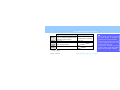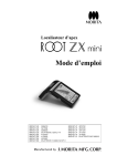
1
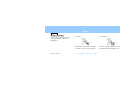
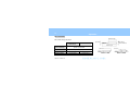
High Speed Air Turbine Handpiece
<with light>
PAR-4HEX-O
PAR-4HX-O
PAR-4HMX-O
PAR-4HEX-O-KV / WH / SR / NK
PAR-4HX-O-KV / WH / SR / NK
PAR-4HMX-O-KV / WH / SR / NK
Operation Instructions
Notice Of Protect Intellectual Property
CN PAT. 03123631.6 US PAT. 5902108
CN PAT. 03123632.4 JP PAT. 3208345
DE PAT. 19807566
JP PAT. 3672781
DE PAT. 19860953
JP PAT. 3795722
DE PAT. 10060152
JP PAT. 3897953
DE PAT. 10320902
JP PAT. 4088475
US PAT. 6676374
JP PAT. 4122174
US PAT. 7048540
JP PAT. 4160319
This manual covers the TWINPOWER TURBINE 4H series handpieces which can be connected to Morita couplings
CP4-O, CP4-WO, or CP5-O and other manufacturer’s couplings.
PAR-4HEX-O *1, PAR-4HEX-O-KV *2 / WH *3 / SR *4 / NK *5
PAR-4HX-O *1, PAR-4HX-O-KV *2 / WH *3 / SR *4 / NK *5
PAR-4HMX-O *1, PAR-4HMX-O-KV *2 / WH *3 / SR *4 / NK *5
*1
*2
*3
*4
*5
Morita CP4-O, CP4-WO and CP5-O coupling
KaVo MULTIflex and MULTIflex LUX coupling: KaVo, MULTIflex, and MULTIflex LUX are registered trademarks for Kaltenbach & Voigt GmbH.
W&H Roto Quick coupling: W&H and Roto Quick are registered trademarks for W&H Dentalwerk Bürmoos GmbH.
SIRONA R/F coupling: Sirona is a registered trademark for Sirona Dental Systems GmbH.
NSK Mach/ Phatelus/ FlexiQuick coupling: Mach, Phatelus and FlexiQuick are registered trademark for NSK NAKANISHI INC.
Operation
2009-09-24
Table of Contents
Introduction ..................................................................1
Parts Identification and Accessories.........................5
Operation .....................................................................8
Handpiece Attachment .............................................8
Inspecting and Sterilizing before Use ..................... 11
Burs and Points ......................................................12
Inserting and Removing Burs .................................15
Maintenance ..............................................................20
After Use ................................................................20
Sterilization .............................................................32
Operation
2009-09-24
Service....................................................................... 34
Parts Replacement ................................................ 34
Regularly Required Replacement Parts................. 63
Other Replacement Parts....................................... 63
Repairs .................................................................. 63
Troubleshooting ..................................................... 64
Technical Information ................................................. 71
Specifications ......................................................... 71
Terminology and Symbols ...................................... 75
Service and Other Contacts ................................... 76
Disposal of Medical Devices .................................. 76
CP4-O/WO and CP5-O Coupling................................ 77
Introduction
1
Introduction
Safety Precautions
Thank you for purchasing a TWINPOWER TURBINE 4H
handpiece.
This instrument is designed for dental treatment such as
grinding, drilling and polishing teeth.
For optimum safety and performance, read this manual
thoroughly before using the unit and pay close attention to the
warnings and notes.
Keep this manual at hand for ready reference.
The instrument must be used in accordance with the
instructions in this manual.
Read this manual thoroughly prior to operating or maintaining
the instrument.
Caution: Federal law restricts this device to sale by or on the
order of a dentist (for U.S.A.).
Operation
2008-04-21
Introduction
2
Note the meaning of the following symbols and expressions:
The user (i.e., clinic, hospital etc.) is responsible for the
management, maintenance and use of medical devices.
WARNING
This warns the user of the possibility of extremely
serious or irreversible injury or a fatal accident.
NOTE
This alerts the user to important points concerning
usage.
Operation
2009-09-24
This instrument must not be used by anyone except legally
qualified dentists and oral surgeons / practitioners.
This instrument must not be used for any other than the
intended purpose as specified in this manual.
Introduction
Disclaimer
The J. Morita Mfg. Corp. will not be responsible for accidents,
equipment damage, or bodily injury resulting from:
1. repairs made by personnel not authorized by the J. Morita Mfg.
Corp.
2. any changes, modifications, or alterations of its products
3. the use of products or equipment made by other manufacturers,
except for those procured by the J. Morita Mfg. Corp.
4. maintenance or repairs using parts or components other than
those specified by the J. Morita Mfg. Corp. and other than in
their original condition
3
5. operating the equipment in ways other than the operating
procedures described in this manual or resulting from the
safety precautions and warnings in this manual not being
observed
6. workplace conditions and environment or installation
conditions which do not conform to those stated in this manual
such as improper electrical power supply
7. fires, earthquakes, floods, lightning, natural disasters, or acts of
God
Operation
2008-04-21
Introduction
4
The J. Morita Mfg. Corp. will supply replacement parts and
be able to repair the product for a period of 10 years after the
manufacture of the product has been discontinued.
* The user (i.e., clinic, hospital etc.) must perform the
inspection procedures specified in the Regular Inspection
Check List every three months.
Warranty is honored only when a claim is accompanied by the
warranty agreement with purchase date, product name and
model, serial number (inscribed on the body of the product)
and name of the distributor.
* Parts must be replaced periodically as necessary.
The Regular Inspection Check List includes a replacement
parts list.
Operation
2009-09-24
Introduction
Parts Identification and Accessories
Parts Identification
Tool Guide
5
Body
Head
Aeroskirt
Push Button
Spray Hole
Cap
Light Guide
Notch
Handpiece Connection
(Connection end differs for various models)
Cap Screw
Operation
2008-04-21
Introduction
6
Accessories
For Inspection and Parts Replacement
Chuck Grip Tester
Spray Hole Wire
No.5010695
No.5250940
(PAR-4HEX-O, PAR-4HX-O)
For Capsule Cartridge Replacement
Cap Tool
Screwdriver
(also used to change lamp)
No.5011440
No.5011328
No.5010840
(PAR-4HMX-O)
(Ethanol disinfectable)
(Ethanol disinfectable)
Operation
2009-09-24
(Autoclavable)
(Ethanol disinfectable)
Introduction
For Spray: AR Spray, 4H Spray Nozzle (Ethanol disinfectable)
AR Spray
4H Spray Nozzle
No.5010212 or
No.5010307
No.5010293
No.5010295
PAR-4HEX-O
PAR-4HEX-O-KV
PAR-4HEX-O-WH
No.5010216
PAR-4HX-O
PAR-4HMX-O
PAR-4HX-O-KV
PAR-4HMX-O-KV
PAR-4HX-O-WH
PAR-4HMX-O-WH
7
No.5010297
No.5010299
PAR-4HEX-O-SR
PAR-4HX-O-SR
PAR-4HMX-O-SR
PAR-4HEX-O-NK
PAR-4HX-O-NK
PAR-4HMX-O-NK
Operation
2008-04-21
Operation
8
Operation
Handpiece Attachment
< Connect >
< Disconnect >
Hold the tube and slide the handpiece
over until it clicks securely into place.
Pull the coupling slightly towards the
tube and then pull the handpiece off.
For Morita CP4-O, CP4-WO and CP5-O
coupling (PAR-4HEX-O, PAR-4HX-O,
PAR-4HMX-O).
Operation
2009-09-24
Operation
9
Except for Morita CP4-O/WO or CP5-O coupling, refer to the user’s manual for the model you have.
PAR-4HEX-O-KV, PAR-4HX-O-KV, PAR-4HMX-O-KV (KaVo MULTIflex and MULTIflex LUX coupling)
PAR-4HEX-O-WH, PAR-4HX-O-WH, PAR-4HMX-O-WH (W&H Roto Quick coupling)
PAR-4HEX-O-SR, PAR-4HX-O-SR, PAR-4HMX-O-SR (SIRONA R/F coupling)
PAR-4HEX-O-NK, PAR-4HX-O-NK, PAR-4HMX-O-NK (NSK MachLite/Phatelus coupling)
Operation
2009-09-24
Operation
10
WARNING
Before attaching the handpiece make sure that the coupling is in good condition (not worn, damaged,
cracked or loose), that the tube O-ring is in place and not pushed in too far, and that the lamp cover on
the tube is tightened securely. Then give it a light tug to make sure it is securely fixed and check its
operation outside the patient’s oral cavity.
Otherwise, air pressure might force the handpiece off its tube connection, resulting in serious injury.
Never exert any force that could cause the handpiece to come off while its running.
NOTE
Handle the motor carefully. Do not drop it or bang it. This could impair its performance.
For information on assembling the CP4-O/WO and CP5-O Coupling refer to the page 77.
Operation
2009-09-24
Operation
Inspecting and Sterilizing before Use
The handpiece is not sterilized before shipping. It must be
autoclaved before being used for the first time.
11
<Inspection>
Before using the handpiece, make sure that the cap and
cap screw are tightened properly and that there is no gap
between the head and the cap. If you discover any
problem with the above items, do not use the handpiece,
but have it repaired instead.
Operation
2008-04-21
Operation
12
Burs and Points
Shank Length
Bur and Point Specifications
PAR-4HEX-O
PAR-4HX-O
Shank Diameter
(ISO standard)
Tip Diameter
Total Length
Shank Length
Operation
2008-04-21
Tip Diam.
Shank Diam.
(ISO Standard)
PAR-4HMX-O
Total Length
φ1.59 ~ φ1.60 mm
φ2.0 mm (max.)
22 mm (max.)
18.5 mm (max.)
10 mm (min.)
7.5 mm (min.)
Flat End
DON’T USE
Grooves
DON’T USE
Operation
13
WARNING
Do not use burs and points:
- which do not conform to ISO standard,
- with scratched or damaged heads or shanks,
- which are bent, twisted, rusty or chipped,
- which have been modified in any way.
Sub-standard or damaged burs and points are very dangerous to use; they can come out and injure the
patient or be swallowed.
Use only short shanked burs with the PAR-4HMX-O.
Never use short-shanked burs and points with the PAR-4HEX-O / PAR-4HX-O; shanks will not reach all
the way to the back of the chuck.
Operation
2008-04-21
Operation
14
NOTE
Always use burs and points with clean shanks; dirty shanks cause the chuck to wear out more quickly and
lose its gripping power.
Always carefully remove all cleaning fluids before inserting a bur into the chuck; some cleaning fluids are
corrosive, and if a bur or point with cleaning fluid on it is inserted, the chuck could be ruined.
If a dirty bur or one with cleaning fluid on it has been inserted by mistake, contact your local dealer or the
J. Morita Office to have the instrument inspected.
Carefully read the instruction manual of the bur maker.
Use only burs made of a single piece of metal; do not use burs whose head is welded to the shank.
Welded joints break easily.
Operation
2008-04-21
Operation
15
Inserting and Removing Burs
<Insert>
Insert
Insert
Hold down the
Push Button
Carefully insert the bur as far as it will go.
Hold down the push button firmly and push the bur all the
way in; then release the push button.
Operation
2008-04-21
Operation
16
<Removal>
WARNING
Pull
Insert burs and points as far as they will go into
the chuck. Never operate the handpiece with a
partially inserted bur or point. A bur or point which
comes out inside the oral cavity could seriously
injure the patient or be swallowed.
GOOD
Operation
2008-04-21
BAD
Hold Down
Hold the push button down and pull the bur straight out.
Operation
17
WARNING
After inserting a bur, always operate the handpiece outside of the oral cavity to make sure it runs
smoothly.
If a bur comes out during use, stop operating the handpiece immediately.
Always use spray and a soft, intermittent touch to avoid injury to the pulp.
Wear protective glasses.
Always take the bur out of a handpiece before putting it back into its holder. Leaving a bur in the
handpiece could result in injury or damage to clothing or other objects.
Operation
2008-04-21
Operation
18
WARNING
Use only the burs and points specified on page 12, Burs and Points. Otherwise, this could result in a
bur coming out inside the oral cavity and being swallowed or in the patient being injured.
Never push the button while the handpiece is running. This could cause the button to heat up, resulting
in burns to the patient or your fingers.
Take care that the push button does not press up against the teeth opposite to the working area
(especially molars); this could cause the button to heat up and damage the tooth pulp. It could also
cause the button to wear out, making it difficult to insert and remove burs.
Operation
2008-04-21
Operation
19
NOTE
Crown removal and other similar operations produce considerable vibration and can cause the bur to get
stuck in the handpiece. Avoid this by frequently removing and reinserting the bur.
In case of abnormal noise or vibration during use, replace the bur. If this eliminates the problem, the bur
was defective. If this does not solve the problem, the handpiece needs to be repaired.
After long usage, wear on bearings results in greater noise.
Operation
2008-04-21
Maintenance
20
Maintenance
After Use
Burs and points may get stuck in the handpiece if they are
left in for too long. Always remove the bur or point after
finishing treatment.
<Disconnect>
Disconnect the handpiece from the tube.
(Remove the point or bur.)
Operation
2008-04-21
<Cleaning>
Use the brush and running water to clean the handpiece.
Maintenance
21
* Clean Spray Hole
If a spray hole gets clogged with impurities in the water,
clean it in the following way
Syringe Nozzle
Spray Hole Wire
Use the wire provided to clean out the spray hole.
After cleaning, blow the hole out with a syringe
and wipe the handpiece with gauze dampened with
Ethanol for Disinfection (Ethanol 80 vol%).
Operation
2008-04-21
Maintenance
22
<Disinfection>
Use a piece of clean gauze and brush to disinfect the whole
surface of handpiece with Ethanol for Disinfection (Ethanol
80 vol%).
Operation
2008-04-21
Maintenance
23
* Thermal washer-disinfector
Handpieces with this symbol may be cleaned and disinfected with a thermal washer-disinfector.
To use a thermal washer-disinfector, first read the operation instructions for the unit.
Strictly follow the instructions attached for cleaning mode and solution.
NOTE
Improper cleaning modes and solutions will damage the handpiece.
Operation
2008-04-21
Maintenance
24
<Lubrication>
Before autoclaving, do not fail to lubricate and clean with
AR Spray.
WARNING
Do not point the spray nozzle at anyone and do not
use the spray near an open flame.
Operation
2008-04-21
NOTE
The handpiece will malfunction without regular AR
spray maintenance.
Never use any type of spray other than AR Spray.
Other lubricants will cause the coupling O-ring to
swell and make it difficult to connect and
disconnect. Also it could make it take longer to
stop in an emergency.
Maintenance
25
There are different spray nozzles for each type of coupling.
Look at the side of the nozzle to check this. Make sure you use the right one.
Look here coupling mark.
No Mark : Morita couplings CP4-O/WO and CP5-O (PAR-4HEX-O, PAR-4HX-O, PAR-4HMX-O)
KV : KaVo coupling (PAR-4HEX-O-KV, PAR-4HX-O-KV, PAR-4HMX-O-KV)
WH : W&H coupling (PAR-4HEX-O-WH, PAR-4HX-O-WH, PAR-4HMX-O-WH)
SR : SIRONA coupling (PAR-4HEX-O-SR, PAR-4HX-O-SR, PAR-4HMX-O-SR)
NK : NSK coupling (PAR-4HEX-O-NK, PAR-4HX-O-NK, PAR-4HMX-O-NK)
Operation
2009-09-24
Maintenance
26
For Handpiece
Connection
Chuck spray Nozzle
Insert all the way.
Shake AR spray can 2 or 3 times before using it. Raise the
lever on the nozzle assembly and swivel the chuck nozzle
down into position. Cover the head with gauze, insert the
nozzle and spray for 2 or 3 seconds.
Operation
2009-09-24
Push the nozzle lever down. Insert the nozzle into the
handpiece connection end and spray for 2 or 3 seconds.
Maintenance
27
WARNING
Lower or raise the nozzle all the way. Otherwise oil could spray out and get in your eyes.
Make sure the lever clicks and locks into place.
Always cover the head with gauze before spraying inside the chuck. If spray accidentally gets into your
eyes, wash them out with plenty of water and see a doctor. Use soap and water to wash off any spray
on your skin.
Operation
2008-04-21
Maintenance
28
<Connect>
<Operate>
<Disconnect>
Connect the handpiece to its tube.
Operate the handpiece for about 15
seconds to blow out excess lubricant.
Disconnect the handpiece.
Operation
2008-04-21
Maintenance
29
<Check Chuck’s Gripping Power>
Carefully insert the chuck tester as far
as it will go.
Firmly hold down the push button and
push the tester all the way in; then
release the button.
Carefully pull on the tester until the
blue line appears.
Operation
2008-04-21
Maintenance
30
If the Blue Line Appears
Chuck is OK.
If the Blue Line Does NOT Appear
Chuck has lost gripping power.
Blue Line
Stop pulling if the blue line appears and let the tester slowly
go back to its original position.
Hold the push button down firmly and take the tester out of
the chuck.
Operation
2008-04-21
Clean the chuck with AR Spray and test it again.
If the chuck still fails the test, replace the Capsule Cartridge.
Maintenance
31
WARNING
Test the chuck at least once a day or if the chuck’s grip seems to be weak.
Never use a chuck which does not have enough grip; a bur could come out in the patient’s mouth and
be swallowed or cause an injury. Stop using the handpiece and have it repaired.
The yellow-green chuck tester is designed specifically for the TWINPOWER TURBINE 4H and cannot
be used for any other handpieces. Do not autoclave the tester; disinfect it by wiping it with Ethanol for
Disinfection (Ethanol 80 vol%).
Operation
2008-04-21
Maintenance
32
Packaging
Wipe the handpiece with a piece of gauze dampened with
Ethanol for Disinfection (Ethanol 80 vol%) and put it in a
sterilization pouch.
Sterilization
<Autoclaving the Handpiece>
Recommended temperature and time: minimum of 5 minutes
at 134°C in a sterilization pouch.
Minimum drying time after sterilization: 10 minutes.
Operation
2008-04-21
WARNING
To prevent the spread of serious, life-threatening
infections such as HIV and hepatitis B, the
handpiece must be autoclaved after the
completion of each patient.
Maintenance
33
NOTE
Do not sterilize in any way except autoclave.
Remove the bur or point before autoclaving.
Autoclave and drying temperatures must not exceed 135°C.
Instruments are extremely hot after autoclaving; do not touch them for at least ten minutes.
The handpiece could be damaged if it is not properly cleaned and lubricated before autoclaving.
Do not touch the push button when operating the handpiece to remove excess spray. This could damage
the cap or the Capsule Cartridge.
Do not leave the handpiece in the autoclave overnight.
Operation
2008-04-21
Service
34
Service
Parts Replacement
The Regular Inspection Check List has a list of replacement parts. Replace these parts periodically or whenever they wear out.
Order parts from your local dealer or the J. Morita Office.
Operation
2008-04-21
Service
Capsule Cartridge with O-ring and screw
No.5010862
PAR-4HEX-O,
PAR-4HEX-O-KV / WH / SR / NK
No.5010863
PAR-4HX-O,
PAR-4HX-O-KV / WH / SR / NK
No. 5010872
PAR-4HMX-O,
PAR-4HMX-O-KV / WH / SR / NK
35
Cap with O-ring and screw
No.5011387
PAR-4HEX-O,
PAR-4HEX-O-KV / WH / SR / NK
PAR-4HMX-O,
PAR-4HMX-O-KV / WH / SR / NK
No.5011386
PAR-4HX-O,
PAR-4HX-O-KV / WH / SR / NK,
Operation
2008-04-21
Service
36
O-ring (exhaust seal)
Cartridge lamp
No.5020550
No.5012320
PAR-4HEX-O-WH,
PAR-4HX-O-WH,
PAR-4HMX-O-WH
PAR-4HEX-O-WH,
PAR-4HX-O-WH,
PAR-4HMX-O-WH
O-ring (prevents loosening of body)
No.5012320
PAR-4HEX-O-WH / NK,
PAR-4HX-O-WH / NK,
PAR-4HMX-O-WH / NK
Operation
2008-04-21
O-ring set
No.5811500
PAR-4HEX-O-NK,
PAR-4HX-O-NK,
PAR-4HMX-O-NK
Service
37
For Morita CP4-O/WO Coupling
Cartridge Lamp
No.5011570
Lamp Cover O-ring
No.5811833
4H Lamp Cover
No.5811832
Operation
2008-04-21
Service
38
For Morita CP4-O/WO and CP5-O Coupling
One-way Spray Valve
No.5811837
Operation
2009-09-24
Coupling Gasket
CP4: No.5811838
CP5: No.7911823
Coupling Wrench for 4H and 5H
No.5011831
O-ring Set for 4H and 5H
No.5811835
Service
39
Capsule Cartridge Replacement
Replace the Capsule Cartridge if worn ball bearings result in
poor or irregular rotation, if burs are difficult to insert or
remove, or if the chuck loses it gripping power.
The Capsule Cartridge and its O-ring wears out and must be
replaced periodically.
The bearings and other parts wear out and make more noise
after a certain period of time.
WARNING
If used in this condition a bur or point could come
out inside the oral cavity and injure the patient or
be swallowed.
NOTE
Do not fail to use the Capsule Cartridge for the
PAR-4HEX, PAR-4HX and the PAR-4HMX.
Operation
2008-04-21
Service
40
Remove old Capsule Cartridge
Cap Screw
Cap
* Check for the PAR-4HEX / PAR-4HX /
PAR-4HMX marking.
Capsule Cartridge
Take the cap screw out with the screwdriver.
Operation
2008-04-21
Service
41
Cap Tool
For PAR-4HEX-O,
PAR-4HMX-O
Push
Out
For PAR-4HX-O
Fit the cap tool securely onto the cap guide and take the cap.
Push the old cartridge out by pressing the aero-skirt around
the chuck opening firmly down on a hard, flat surface.
Operation
2008-04-21
Service
42
Screw the nozzle assembly onto the spray can with the
nozzle for the handpiece connection sticking straight out.
Insert the nozzle into the handpiece connection end and
spray for 2 or 3 seconds.
Operation
2008-04-21
Connect the handpiece to its tube. Operate the handpiece
for 2 or 3 seconds to blow out excess lubricant and clean the
head. Clean the cap with AR spray.
Service
43
Insert new cartridge
Spray a little AR spray inside the head.
Operation
2008-04-21
Service
44
(PAR-4HEX-O, PAR-4HX-O)
If the O-ring has come off, line up the narrow section of
the O-ring and projection as shown in the illustration and
reattach it. If the narrow section of the O-ring is not
properly lined up, the spray will not work properly.
Narrow section of O-ring
Operation
2008-04-21
Projection
Service
45
Projection
Groove
Make sure all 3 O-rings are on the cartridge. Line up the
projection on the cartridge with the groove in the head
and push it all the way in.
Screw the cap on a little but leave a gap large enough for a
new O-ring. Use tweezers to put the O-ring (provided with
cartridge) between the cap and head.
Operation
2008-04-21
Service
46
WARNING
The O-ring for the cap must be replaced with the
new one provided. Otherwise, the cap could
come off inside the patient’s mouth and be
swallowed or cause an injury.
Replace the cap if the projection on the inside is worn away.
Operation
2008-04-21
Service
Screw the cap down manually until it is seated on the head.
Do not use the cap tool to screw down the cap from the
beginning; this could damage the threads.
47
Fit the cap tool securely onto the cap and tighten up the cap.
Line up the notch on the cap with the hole for the cap screw.
Operation
2008-04-21
Service
48
Align notch and hole
Do not tighten the cap too much. This could damage the
threads so that the hole and notch no longer line up.
Operation
2008-04-21
Tighten up the cap screw with the screwdriver.
Service
49
WARNING
Make sure the notch on the cap is lined up with the hole for the screw.
If the notch goes beyond the hole, the threads are worn; contact your local dealer or the J. Morita Office
to have the instrument repaired.
Make sure the cap screw is tight enough. If the cap screw or cap comes out in a patient’s mouth, it
could be swallowed or cause an injury.
Make sure there is no gap between the cap and the head. If there is, do not use the handpiece; have
it repaired.
NING
Operation
2008-04-21
Service
50
Insert the nozzle into the handpiece connection end and
spray for 2 or 3 seconds.
Operation
2008-04-21
Connect the handpiece and operate it for at least 15 seconds
to blow the excess lubricant out of the head. Then wipe the
handpiece with a piece of gauze.
Service
51
Always use AR spray after replacing the cartridge.
* Order Capsule Cartridges from your local dealer or the J. Morita Office.
* When ordering, always specify the model: PAR-4HEX, PAR-4HX or PAR-4HMX.
Replacing the cartridge lamp
For CP4-O/WO (PAR-4HEX-O, PAR-4HX-O, PAR-4HMX-O) and for W&H (PAR-4HEX-O-WH, PAR-4HX-O-WH,
PAR-4HMX-O-WH), only
For KaVo (PAR-4HEX-O-KV, PAR-4HX-O-KV, PAR-4HMX-O-KV), SIRONA (PAR-4HEX-O-SR, PAR-4HX-O-SR, PAR-4HMX-O-SR) and
NSK (PAR-4HEX-O-NK, PAR-4HX-O-NK, PAR-4HMX-O-NK) lamp replacement, refer to the user’s manual for the couplings of various
makers.
Operation
2008-04-21
Service
52
WARNING
Turn off the power switch to avoid the risk of burns and electrical shock.
The lamp and its cover are quite hot immediately after the lamp has burned out. Avoid burning yourself;
do not touch these parts.
NOTE
Do not leave fingerprints or any foreign substances on the new lamp. These could cause the lamp to
break as soon as it is turned on, which could cause an injury. If necessary use Ethanol for Disinfection
(Ethanol 80 vol%) to clean the lamp.
Operation
2008-04-21
Service
53
For CP4-O/WO (PAR-4HEX-O, PAR-4HX-O, PAR-4HMX-O)
Disconnect the handpiece from the main tube.
Turn off the power switch on the chair, and take the tube’s
lamp cover off using the square hole on the cap tool.
Take the lamp out of its socket.
Operation
2008-04-21
Service
54
Line up the grooves on the new lamp with the leads inside
the socket and push it all the way into place.
Operation
2008-04-21
Screw the lamp cover on manually and then tighten it up
using the square hole on the cap tool.
Service
55
Reconnect the handpiece and operate it to make sure the lamp lights up.
WARNING
Make sure the lamp cover is screwed all the way down. If the handpiece is not properly connected to
the tube, air pressure could cause the tube to blow off, which could cause an injury.
NOTE
Use only cartridge lamps made specifically for this model.
* Order lamp cartridges from your local dealer or the J. Morita office.
Operation
2008-04-21
Service
56
For W&H (PAR-4HEX-O-WH, PAR-4HX-O-WH, PAR-4HMX-O-WH)
Body C
O-ring
(Exhaust seal)
O-ring
(Keeps body tight)
Disconnect the handpiece from the main tube. Turn off the lamp
and rotate body C in the direction shown in the illustration.
Operation
2008-04-21
Take out the old lamp with tweezers.
Service
Install the lamp so that the rim does not go in too far.
Socket
GOOD
57
BAD
NOTE
If the rim goes into the socket, the connection
could be defective, or the lamp could come out.
Rim
Operation
2008-04-21
Service
58
WARNING
Body C
Make sure Body C is screwed all the way down. If
the handpiece is not properly connected to the
tube, air pressure could cause the tube to blow
off, which could cause an injury.
NOTE
Screw body C back into its original place. Reconnect the
handpiece and operate it to make sure the lamp lights up.
Operation
2008-04-21
Use only cartridge lamps made specifically for this
model.
* Order lamp cartridges from your local dealer or the
J. Morita office.
Service
Replacing the O-rings.
PAR-4HEX-O-NK, PAR-4HX-O-NK, PAR-4HMX-O-NK, only
O-ring (prevent loosening of body)
O-rings
Body C
59
3. Take off the O-rings with tweezers or some
other suitable tool.
4. Put on the new O-rings.
5. Spray the O-rings with AR Spray.
6. Replace Body C.
WARNING
1. Take the handpiece off its main tube.
2. Turn Body C in the illustration in the direction shown by the
arrow and take it off.
Tighten Body C securely all the way.
Otherwise air could leak out and prevent a
proper connection with the coupling.
Operation
2008-04-21
Service
60
Storage
Storage conditions
Temperature -10 ~ 70 ºC
Humidity 10 ~ 85 % RH (without condensation)
Atmospheric pressure 700 ~ 1,060 hPa
* Avoid frequent exposure to direct sunlight.
* Store the handpiece in a clean, dry place after autoclaving it.
Operation
2008-04-21
Service
61
Inspection
Regular Inspection
* Use the Inspection Check List provided to inspect the instrument every 3 months.
* It is assumed that the user will perform regular maintenance and inspection procedures. However, if necessary or desired,
these may be performed by a trained professional qualified to repair medical devices. Contact your local dealer or the J.
Morita Office.
Operation
2008-04-21
Service
62
Regular Inspection Check List
Item
Procedure
Chuck Gripping Strength
Use the Chuck Tester to check the chuck’s gripping strength. Replace the Capsule
Cartridge if the chuck has lost its gripping strength.
Cap Tightness
Make sure that the cap and the cap screw are tightened properly.
Rotation and Spray
Make sure the handpiece operates smoothly and emits a fine, misty spray.
Operation
2008-04-21
Service
63
Regularly Required Replacement Parts
Capsule Cartridge
(PAR-4HEX-O, PAR-4HX-O, PAR-4HMX-O)
Other Replacement Parts
Cap
Repairs
Contact your local dealer or the J. Morita Office for handpiece and coupling repairs etc.
Operation
2008-04-21
Service
64
Troubleshooting
The user should check the following pages if he thinks the instrument is not operating normally.
Operation
2008-04-21
Service
Poor Rotation
65
Lubricate with AR Spray.
Disconnect handpiece and step on foot pedal.
Does air comes out of the end of the tube with enough force?
N O
Defective tube. Contact serviceman.
YES
If other handpieces work OK, replace the Capsule Cartridge.
Make sure the Capsule Cartridge is the correct one.
Operation
2008-04-21
Service
66
Poor Spray
Disconnect handpiece. Check coupling connection. Step on foot pedal.
Does air comes out of the end of the tube with enough force?
OR
Operation
2008-04-21
N O
Defective tube or water lines inside chair.
YES
Replace the coupling’s O-ring.
Service
67
Clean spray hole.
After cleaning, blow the
hole out with a syringe
and wipe the handpiece
with gauze dampened with
Ethanol for Disinfection
(Ethanol 80 vol%).
Use the wire provided to
clean out the spray hole.
Spray Hole Wire
Syringe Nozzle
Make sure the O-rings on the Capsule Cartridge are properly installed.
Operation
2008-04-21
Service
68
Cannot insert burs or points
Check that burs and points are OK.
NO
YES
Operation
2008-04-21
Use only burs and points that are suitable and in good shape.
Service
69
Spray into chuck.
Screw the nozzle assembly onto
the spray can with nozzle for the
chuck sticking straight out.
Cover the head with gauze, insert
the nozzle and spray into the
chuck for 2 or 3 seconds.
Connect the handpiece and
operate it for 15 seconds to
blow out excess spray.
Then wipe it clean with a
piece of gauze.
Still cannot insert burs and points.
Replace the Capsule Cartridge. Make sure the Capsule Cartridge is the correct one.
Operation
2008-04-21
Service
70
Light doesn’t work
Lamp may be burned out.
Operation
2008-04-21
N O
Check tube and chair.
YES
Replace lamp.
Technical Information
71
Technical Information
Specifications
Name : TWINPOWER TURBINE 4H
Model : with light
Operation
2008-04-21
Technical Information
72
PAR-4HEX-O
CP4-O/WO
KV
CP5-O
Bearing
Chuck
Rotor
Recommended Air Pressure
Air Pressure Range
Air Pressure
(at handpiece Water Supply Pressure
connection)
Tip Air Pressure
Exhaust Air Pressure
Operation
2009-09-24
WH
SR
PAR-4HX-O
CP4-O/WO
NK
KV
CP5-O
WH
SR
PAR-4HMX-O
CP4-O/WO
NK
KV
CP5-O
Ball Bearing
Push Chuck
Autoclavable Capsule Cartridge
0.23~0.25 (MPa)
0.2~0.29 (MPa)
0.05~0.2 (MPa)
0.2 minimum (MPa)
0.03 maximum (MPa)
WH
SR
NK
Technical Information
PAR-4HEX-O
CP4-O/WO
KV
CP5-O
Speed (rpm)
Air Flow (NL/min)
Weight (g)
Size
Head Diameter (mm)
Head Height (mm)
Length (mm)
Number of water spray nozzle
WH
SR
PAR-4HX-O
CP4-O/WO
NK
KV
CP5-O
370,000±30,000
51
57
51
Φ10.5
50
120
115
110
103
73
48
51
13.2
98
120
3
WH
SR
350,000±30,000
37±3
57 51 50
Φ12.0
115
110 103
PAR-4HMX-O
CP4-O/WO
NK
KV
CP5-O
WH
SR
NK
370,000±30,000
48
51
98
120
57
51
50
Φ10.5
10.6
115 110 103
1
Operation
48
98
2009-09-24
Technical Information
74
Operating
Conditions
Lamp Voltage
Lamp Power
Temp.: 10 ~ 40° C
Humidity: 30 ~ 75 % RH
Atmosph. Pressure: 700 ~ 1,060 hPa
Max. 3.3 V ± 0.05 V D.C.
(for coupling contacts)
Max. 2.4 W
Lamp power supply must conform to IEC60601-1 and
voltage is SELV (special safe low voltage).
RNING Operating
Operation
2008-04-21
NOTE
The handpiece will lose both speed and torque in
direct proportion to the amount to which the
exhaust air pressure exceeds 0.03 MPa.
WARNING
The PAR-4HEX-O, the PAR-4HX-O and the PAR4HMX-O need special precaution regarding EMC.
Portable and mobile RF communications
equipment can affect the PAR-4HEX-O, the
PAR-4HX-O and the PAR-4HMX-O.
Technical Information
Terminology and Symbols
Name
75
Model
Ball Bearing Type
Manufacturer
Autoclavable up to 135°C
Serial Number
Requires AR Lubrication
Handpieces with this symbol may
be cleaned and disinfected with a
thermal washer-disinfector.
The first character of the serial number
specifies the year of manufacture as follows:
V: 2007 W: 2008 X: 2009
CE (0197) marking
Conforms to European medical
device Directive 93 / 42 / EEC.
Operation Instructions
Manufacturer
Authorized representative in
the European Community
Operation
2009-09-24
Technical Information
76
Service and Other Contacts
For repair or other types of service contact your local dealer or the J. Morita Office.
Disposal of Medical Devices
Any medical devices which could possibly be contaminated must be first decontaminated by the responsible doctor or
medical institution and then be disposed of by an agent licensed and qualified to handle medical and industrial waste.
Operation
2009-09-24
CP4-O/WO and CP5-O Coupling
CP4-O <with light> Coupling
CP4-WO <with light and Spray Control> Coupling
* Before use check the following items: Does the connection end
of the tube match the coupling? Lamp voltage is correct.
This coupling cannot be connected to a tube that does not have
light capability.
Spray Air
Water
Drive Air
Exhaust
Electrical Contacts
77
CP5-O <with Fiber Optic> Coupling
* Before use check the following items: Does the connection
end of the tube match the coupling?
This coupling cannot be connected to a tube that does not
have light capability. This coupling cannot be connected to a
4-hole tube.
Spray Air
Water
Drive Air
Exhaust
Fiber Optic
Operation
2009-09-24
CP4-O/WO and CP5-O Coupling
78
Model
Weight
Lamp
Voltage
Lamp
Power
CP4-O/WO
CP5-O
CP4-O <with light>
CP5-O <with Fiber Optic>
CP4-WO <with light and Spray Control>
ISO 9168 Type 2 Coupling
ISO 9168 Type 3 Coupling
27 ± 10 g
27 ± 10 g
Max. 3.3 V ± 0.05 V D.C.
(for coupling contacts)
Max. 2.4 W
* Lamp power supply must be conformed to IEC60601-1 and voltage is SELV (special
safe low voltage).
Operation
2009-09-24
NOTE
For the CP-4, the lamp will burn
out more quickly if voltage is
greater than the value specified.
For the CP-4, the lamp may burn
out more quickly if the chair is set
for a long fade out time.
For the CP-4, the lamp may burn
out more quickly if the chair applies
and cuts off the voltage suddenly.
CP4-O/WO and CP5-O Coupling
1. Connect Coupling
79
NOTE
Before connection, make sure the tube connector
is clean and free of debris.
The light will lose its brightness if the end of the
fiber optic cable is scratched or otherwise
damaged by being dropped for instance.
Line up the projections on the coupling with the indentations
in the tube and then tighten up the cover nut.
Operation
2009-09-24
CP4-O/WO and CP5-O Coupling
80
NOTE
Air or water may leak if the coupling is not tightened
up enough.
Tighten securely with the wrench provided.
* Before first using the coupling or if the handpiece-coupling
connection gets stiff, take the nozzle off the AR Spray can and
lightly spray the coupling’s o-rings.
Operation
2009-09-24
CP4-O/WO and CP5-O Coupling
2. Cleaning
Wipe the outside cover with Ethanol for Disinfection
(Ethanol 80 vol%).
81
NOTE
Coupling must NOT be autoclaved or cleaned
ultrasonically.
The coupling could be damaged if it is soaked in
Ethanol for Disinfection (Ethanol 80 vol%) or
cleaned with a strong, corrosive solution.
Clean both ends of the light guide if the light
seems to have lost its brightness.
Operation
2009-09-24
CP4-O/WO and CP5-O Coupling
82
3. Spray Adjustment (CP4-WO)
Indicator
Turning the dial in the
direction indicated by the
arrow in the illustration
will gradually reduce the
♦
amount of spray and then
Spray Control Dial
reach 0.
Tube Ring
For maximum spray,
continue the turning the dial until the “W” matches up with
the indicator. (See illustration.)
Operation
2009-09-24
WARNING
Hold the tube ring to adjust the amount of spray.
The handpiece could come off its connection and
injure someone if it is held by the part indicated by
the mark ( ♦ ).
NOTE
If the coupling is not securely tightened up with
the wrench, water or air could leak.
CP4-O/WO and CP5-O Coupling
4. Coupling O-ring Replacement
83
WARNING
Remove and replace all the old O-rings; otherwise
air pressure could cause the tube to blow off,
resulting in an injury.
Replace the five O-rings if air or water starts to leak. After
replacement, remove the 4H Spray Nozzle from the AR
Spray can and lightly coat the O-rings with AR Spray.
Operation
2009-09-24
CP4-O/WO and CP5-O Coupling
84
5. Replacing One-way Spray Valve
Inspecting One-way Valve
Cutting debris and other foreign matter could be sucked
into the water tube if the one-way valve is not working
properly. Inspect it once a month.
1. Remove the needle from a plastic syringe and fit the end
over the spray pipe.
2. Check that there are no gaps between it and the gasket.
3. Pull the plunger out a little and then release it. If the
plunger moves back in, the valve is OK.
4. Replace the valve if the plunger does not go back in at all.
Operation
2009-09-24
CP4-O/WO and CP5-O Coupling
6. Replacement
1. Use a needle or similar object to remove the gasket.
2. Remove the old valve and replace it with a new one.
3. Replace the gasket in its original position.
85
NOTE
Make sure not to damage the part of the gasket
that presses up against the water pipe as this
creates a crucial seal.
Operation
2009-09-24
INDEX
4H Spray Nozzle, 7
Accessories, 6
AR Spray, 24, 26
Autoclaving the Handpiece, 32
Burs, 12
Cap, 35
Cap Tool, 6, 41
Capsule Cartridge, 35
Cartridge Lamp, 36, 37
Contacts, 76
CP4-O / WO Coupling, 77
CP5-O Coupling, 77
Disinfection, 32
Disposal, 76
Handpiece Attachment, 8
Inserting, 15
Inspection, 11, 61
O-ring, 36, 37
Parts, 5
Points, 12
Regular Inspection, 4, 61
Removal, 16
Repairs, 63
Replacement, 6, 63
Safety Precautions, 1
Screwdriver, 6
Specifications, 71
Storage, 60
Troubleshooting, 64
EU Authorized Representative under the European Directive 93/42/EEC
MEDICAL TECHNOLOGY PROMEDT CONSULTING GMBH
Altenhofstraße 80, 66386 St. Ingbert, Germany
TEL: +49-6894-581020 FAX: +49-6894-581021
The authority granted to the authorized representative, MEDICAL TECHNOLOGY PROMEDT Consulting GmbH,
by J. Morita Mfg. Corp. is solely limited to the work of the authorized representative with the requirements
of the European Directive 93/42/EEC for product registration and incident report.
J. MORITA MFG. CORP.
680 Higashihama Minami-cho,
Fushimi-ku, Kyoto, 612-8533 Japan
http://www.jmorita-mfg.com
Distributors
J. MORITA CORPORATION
Tokyo Office : 11-15, 2-Chome Ueno,
Taito-ku, Tokyo, 110-8513 Japan
Osaka Office : 33-18, 3-Chome Tarumi-cho,
Suita, Osaka, 564-8650 Japan
http://asia.morita.com http://oceania.morita.com
J. MORITA USA, Inc.
9 Mason, lrvine, CA 92618 U.S.A..
TEL:+1-949-581-9600 FAX: +1-949-465-1095 http://www.jmoritausa.com
J. MORITA EUROPE GMBH
Justus-Von-Liebig-Strasse 27A,
D-63128 Dietzenbach Germany
TEL: +49-6074-836-0 FAX: +49-6074-836-299 http://www.jmoritaeurope.de
SIAMDENT CO., LTD.
444 Olympia Thai Tower, 3rd Floor, Ratchadapisek Road,
Samsennok, Huay Kwang, Bangkok 10310, Thailand
TEL: +66-2-512-6049 FAX: +66-2-512-6099 http://www.siamdent.com
J. MORITA CORPORATION Australia and New Zealand
Suite 2.05, Aero 247 Coward Street Mascot NSW 2020, Australia
TEL: +61-2-9667-3555 FAX: +61-2-9667-3577 http://oceania.morita.com
K 8,000
’09.10. ○
PUB. H5054-E-1 Printed in Japan