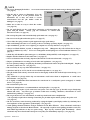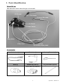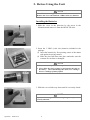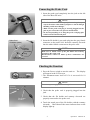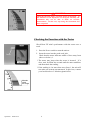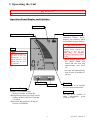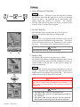
1
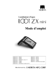
Apex Locator
Operation Instructions
US PAT. 5096419
US PAT. 5211556
US PAT. 5295833
US PAT. APPLN. 12/075, 714
DE PAT. 4126753
DE PAT. 4139424
DE PAT. 4232487
DE PAT. APPLN. 10 2008 012 677.2
JP PAT. 2873722
JP PAT. 2873725
JP PAT. 3071270
JP PAT. 3113109
JP PAT. 3113095
JP PAT. APPLN. 2007-068512
Thank you for purchasing the Root ZX mini.
For optimum safety and performance, read this manual thoroughly before using the unit and pay close
attention to warnings and notes. Keep this manual in a readily accessible place for quick and easy
reference. This manual contains essential safety information.
ATTENTION
1. J. Morita Mfg. Corp. will not be responsible for accidents, equipment damage, or bodily injury
resulting from repairs made by personnel not authorized by the J. Morita Mfg. Corp.
2. J. Morita Mfg. Corp. will not be responsible for accidents, equipment damage, or bodily injury
resulting from any changes, modifications, or alterations of its products.
3. J. Morita Mfg. Corp. will not be responsible for accidents, equipment damage, or bodily injury
resulting from the use of products or equipment made by other manufacturers, except for those
procured by the J. Morita Mfg. Corp.
4. J. Morita Mfg. Corp. will not be responsible for accidents, equipment damage, or bodily injury
resulting from maintenance or repairs using parts or components other than those specified by the
J. Morita Mfg. Corp. and in their original condition.
5. J. Morita Mfg. Corp. will not be responsible for accidents, equipment damage, or bodily injury
resulting from operating the equipment in ways other than the operating procedures described in
this manual or resulting from not following the cautionary remarks and warnings in this manual.
6. J. Morita Mfg. Corp. will not be responsible for accidents, equipment damage, or bodily injury
resulting from workplace conditions and environment or installation conditions such as improper
electrical power supply which do not conform to those stated in this manual.
7. J. Morita Mfg. Corp. will not be responsible for accidents, equipment damage, or bodily injury
resulting from fires, earthquakes, floods, lightning, natural disasters, or acts of God.
8. J. Morita Mfg. Corp. will supply replacement parts and be able to repair the product for a period of
10 years after the manufacture of the product has been discontinued.
* Inspect the unit every 6 months in accordance with the Maintenance and Inspection items.
* Refer to the replacement parts lists and replace worn parts whenever necessary.
Operation 2009-01-21
CONTENTS
1. Parts Identification .....................................................................................................1
2. Before Using the Unit ................................................................................................2
Connecting the Probe Cord ...................................................................................3
Checking the Function ..........................................................................................3
Checking the Function with the Tester..................................................................4
3. Operating the Unit......................................................................................................5
Operation Panel Display and Switches .................................................................5
Settings..................................................................................................................6
Meter Display........................................................................................................7
Operating the Unit.................................................................................................8
Root Canals not suitable for Electronic Measurement........................................11
Root ZX mini Meter Reading and Radiography.................................................13
4. After Using the Unit.................................................................................................14
5. Replacing Batteries ..................................................................................................15
6. Sterilization and Replacement Parts ........................................................................16
Sterilization .........................................................................................................16
Replacement Parts...............................................................................................16
Storage.................................................................................................................16
7. Maintenance and Inspection ....................................................................................17
8. Troubleshooting .......................................................................................................18
9. Technical Description ..............................................................................................20
10. Appendix- Electromagnetic declaration ..................................................................23
Operation 2009-01-21
ATTENTION CUSTOMERS
Do not fail to receive clear instructions concerning the various ways to use this equipment as
described in this accompanying Operator’s Manual.
Fill out and sign the warranty and give the dealer from whom you purchased the equipment his
copy.
ATTENTION DEALERS
Do not fail to give clear instructions concerning the various ways to use this equipment as
described in this accompanying Operator’s Manual.
After instructing the customer in the operation of the equipment, have him fill out and sign the
warranty. Then fill in your own section of the warranty and give the customer his copy. Do
not fail to send the manufacturer’s copy to J. Morita Mfg. Corp.
Prevent Accidents
Most operation and maintenance problems result from insufficient attention being paid to basic safety
precautions and not being able to foresee the possibilities of accidents.
Problems and accidents are best avoided by foreseeing the possibility of danger and operating the unit in
accordance with the manufacturer’s recommendations.
First thoroughly read all precautions and instructions pertaining to safety and accident prevention; then,
operate the equipment with the utmost caution to prevent either damaging the equipment itself or
causing bodily injury.
Note the meaning of the following symbols and expressions:
WARNING
This warns that it may result serious injury of the patient or
operator if the instructions are not followed properly.
PROHIBITION
The user can not use in such a way that may result in serious injury
of the patient or operator.
NOTE
This alerts the user to the possibility of damage to the equipment,
potential injury of the patient or operator, or important points
concerning operation and performance.
The user ( e.g. the hospital, clinic etc. ) is the party responsible for the maintenance and proper operation
of a medical device.
Medical devices must only be operated by dentists and other legally licensed professionals.
Do not use this equipment for anything other than its specified purpose.
Caution: Federal law restricts this device to sale by or on the order of a dentist (for U.S.A.).
i
Operation 2009-01-21
WARNING
• This unit must not be connected to or used in combination with any other apparatus or system. It must not
be used as an integral component of any other apparatus or system.
J. Morita Mfg. Corp. will not be responsible for accidents, equipment damage, bodily injury or any other
trouble which results from ignoring this prohibition.
• Accurate canal measurement is not always possible depending on the shape and condition of the tooth as
well as a decline in the equipment’s performance.
• Do not use damaged file holders; an accurate measurement can not be made with a damaged file holder.
• When a continuous tone is heard while the main power switch is on and without any operation, some
electrical part may be malfunctioning. Do not use the unit and send the unit to J. Morita regional office
for repairing.
• Prescription unit.
• A rubber dam should be used when performing endodontic treatment.
• Check the Root ZX mini’s operation before each patient. If the indicators in the display do not all appear
normally, the instrument may not be able to make an accurate measurement. In this case, stop using the
instrument and have it repaired. ( see page 4 )
• Never connect the Root ZX mini to any device not approved by the J. Morita Corp. ( see page 5 )
• The meter readings 1, 2, and 3 do not correspond to any actual distance and should only be used as
estimates. ( see page 5 )
• Never use the unit if the battery power indicator is flashing on and off. The unit may not function properly
if the battery power is low. ( see page 5, 15 )
• The Memory Bar should only be used as an estimate. You may need to change it during enlargement and
cleaning. If there seems to be some problem, stop using the instrument immediately. ( see page 6 )
• Check the settings displayed after selecting memories. ( see page 7 )
• In some cases such as a blocked canal, a measurement cannot be made. ( see page 7 )
• Always check the measurement with an x-ray. In some cases, an accurate measurement cannot be made
because of the canal shape, unusual cases, or poor performance of the instrument. ( see page 7 )
• Stop using the instrument immediately if you sense something odd or abnormal while taking a measurement.
( see page 7 )
• Do not use an ultrasonic scaler with the contrary electrode attached to the patient.
the scaler could interfere with canal measurements. ( see page 8 )
Electrical noise from
• Make sure that the contrary electrode, file holder etc. do not come into contact with an electric power source
such as an electrical socket. This could result in a severe electrical shock. ( see page 8 )
• Autoclave file holder and contrary electrode after each patient. ( see page 16 )
• Some care must be taken concerning electromagnetic compatibility (EMC) when using the Root ZX mini
(hereafter referred to as the RCM-7). Refer to the user’s manual and other attached documents for EMC
information regarding installation and operation. ( see page 23 )
• Both portable and movable radio frequency transmitters may have some effect on the RCM-7. ( see page
23 )
• Using replacement parts or accessories not supplied by the original manufacturer or vender could adversely
affect the EMC performance of the RCM-7. ( see page 23 )
• As far as possible, do not use the RCM-7 near or simultaneously with other devices. If this cannot be
avoided, observe carefully and make sure both the RCM-7 and the other device operate normally. ( see page
23 )
• Use of the parts other than those accompanied or specified by J. Morita Mfg. Corp. may result in increased
EMC emissions or decreased EMC immunity of the RCM-7. ( see page 26 )
Operation 2009-01-21
ii
PROHIBITION
• Do not use this unit in conjunction with an electric scalpel or on patients who have a pacemaker.
• Blocked canals cannot be accurately measured.
• This unit must not be connected to or used in combination with any other apparatus or system. It must
not be used as an integral component of any other apparatus or system.
J. Morita Mfg. Corp. will not be responsible for accidents, equipment damage, bodily injury or any other
trouble which results from ignoring this prohibition.
• Illumination devices such as fluorescent lights and the Film viewer which use an inverter can cause the
Root ZX mini to operate erratically. Do not use the Root ZX mini near devices such as these.
• Electromagnetic wave interference could cause this device to operate in an abnormal, random and possibly
dangerous manner. Cellular phone, transceivers, remote controls and all other devices which transmit
electromagnetic waves located inside the building should be turned off.
NOTE
• Root ZX mini is shipped without the batteries installed.
size) batteries. ( see page 2 )
Remove the cover and install the 3 LR03 (AAA
• Do not reverse the plus and minus poles. ( see page 2 )
• Never allow the spring contact to push against the edge of the battery.
causing a short or a leakage of battery liquid. ( see page 2 )
This could damage the outer cover
• After installation, give the cover a light tug to confirm it is securely attached. ( see page 2 )
• Handle the Root ZX mini carefully; do not drop, bump or expose the unit to other kinds of impacts or
shocks. Rough handling could cause damage. ( see page 3 )
• Make sure the probe cord plug is securely plugged into the jack. A poor connection can prevent
measurement. ( see page 3 )
• Do not drop anything on or bang the probe cord plug after it has been inserted into the jack. ( see page 3 )
• Make sure to match colors of the file holder and contrary electrode to the probe cord. Measurements
cannot be made if these connections are reversed. ( see page 3 )
• The unit may turn off if its side is bumped. ( see page 3 )
• The Flash Bar cannot be set beyond the Apex. ( see page 6 )
• The Memory Bar cannot be set beyond the Apex. ( see page 6 )
• The Memory Bar can be set at a different point for each of the 3 memories. ( see page 6 )
• The Memory Bar will stay wherever you set it until the Root ZX mini is turned off, but it will not be
memorized. ( see page 6 )
• The volume of the beep that sounds when the unit is turned on cannot be adjusted. ( see page 7 )
• Do not let the file touch the gums.
This will cause the meter to jump to Apex. ( see page 7 )
• If the canal is extremely dry, the meter may not move until it is quite close to the apex.
not move, try moistening the canal with oxydol or saline. ( see page 7 )
If the meter does
• Occasionally the canal length indicator bar will make a sudden and large movement as soon as the file is
inserted into the root canal, but it will return to normal as the file is advanced down towards the apex. ( see
page 7 )
• The contrary electrode could cause an adverse reaction if the patient has an allergy to metals.
patient about this before using the contrary electrode. ( see page 8 )
Ask the
• Take care that medicinal solutions such as formalin cresol (FC) or sodium hypochlorite do not get on the
contrary electrode or the file holder. These could cause an adverse reaction such as inflammation. ( see
page 8 )
• Always clip the file holder to the upper part of file shaft, near the handle. The metal and plastic part of
the file holder can be damaged if they are attached to the file’s cutting part or the transition to the cutting
part. ( see page 9 )
• Use files and reamers with plastic handles only. If the file has a metal handle, electrical leakage will
occur when the handle is touched by fingers and it will prevent an accurate root canal measurement.
Even if the file handle is made of plastic, make sure not to touch the metal part of the file with finger. ( see
page 9 )
iii
Operation 2009-01-21
NOTE
• Do not use damaged file holders.
( see page 9 )
An accurate measurement cannot be made using a damaged file holder.
• Clip the file as shown in illustration
right. If the file is in the position
illustration #2, it may not make
measurement and the file holder
damaged. ( see page 9 )
GOOD
BAD
#1 to the
shown in
a correct
could be
1
• Make sure to take an x-ray to check the results.
( see page 10 )
• Do not pull directly on the cords when connecting or disconnecting the
probe and file holder. Always grip the connectors to connect and
disconnect cords. ( see page 14 )
2
BAD
BAD
• Do not wrap the probe cord around the body of the main unit. ( see page 14 )
• Do not reverse the plus and minus poles. ( see page 15 )
Cord
• Never allow the spring contact to push against the edge of the battery.
This could damage the outer cover causing a short or a leakage of battery liquid. ( see page 15 )
• After installation, give the cover a light tug to confirm it is securely attached. ( see page 15 )
• Always use LR03 alkaline, oxyride, or manganese dry cells. (Manganese dry cells will not last as long as
oxyride or alkaline dry cells.) Never use rechargeable nickel-hydrogen or nickel-cadmium batteries. ( see
page 15 )
• All the dry cells should be of the same type: i.e., all alkaline, all OxyrideTM , or all manganese. ( see page 15 )
• Replace all three batteries at the same time. ( see page 15 )
• Never use batteries that are leaky, deformed, discolored or otherwise abnormal. ( see page 15 )
• Dispose of old batteries according to local codes and regulations. ( see page 15 )
• In case of battery leakage, carefully dry the battery terminals and remove all of the leaked liquid.
the battery with a new one. ( see page 15 )
Replace
• Do not sterilize in any way other than autoclave. ( see page 16 )
• Autoclave and dry at 135°C, but do not exceed that temperature. ( see page 16 )
• The file holder and contrary electrode must be thoroughly washed and cleaned before autoclaving. ( see
page 16 )
• Any chemicals or foreign debris left on instruments could cause them to malfunction or could cause
discoloration. ( see page 16 )
• It is highly recommended that instruments be autoclaved in a sterilization pouch (wrapped) or similar
device. ( see page 16 )
• Do not autoclave probe cord.
• Follow the manufacturer’s recommendations to disinfect files. ( see page 16 )
• Do not wipe the surface of the main unit and probe cord with any type of alcohol except disinfecting
ethanol (80 vol%). Any other type of solution could cause cracking, cloudiness, discoloration or some
similar kind of damage. ( see page 16 )
• Do not get the box too wet with ethanol; it could seep inside and cause a malfunction.
* Be especially careful when cleaning around the port for data output and the jack for the probe cord.
( see page 16 )
• On rare occasions, static electricity produced by wiping the liquid crystal display with a dry cloth may have
some influence on the appearance of the display. ( see page 16 )
• Avoid spilling chemical solutions used for treatment on the Root ZX mini. These chemicals could cause
damage, deform or discolor the Root ZX mini. Be especially careful to avoid spilling formalin cresol (FC)
and sodium hypochlorite as they are quite strong. Wipe up any chemical spills immediately. (Some
chemicals may leave discoloration and spots even if they are immediately wiped up.) ( see page 16 )
Operation 2009-01-21
iv
1. Parts Identification
Intended use
This unit can be used to detect the apex of root canal.
LCD Screen
File Holder
Contrary Electrode
Set Switch
Power Switch
Strap Holes
Probe Cord
Data Output Port
(to transmit display data)
Accessories
Probe Cord (1)
File Holder (3)
Contrary Electrode (5)
Tester (1)
Alkaline Dry Cells (3)
Long File Holder (Option)
(LR03 (AAA size) batteries)
1
Operation 2009-01-21
2. Before Using the Unit
NOTE
Root ZX mini is shipped without the batteries installed.
Remove the cover and install the 3 LR03 (AAA size) batteries.
Installing the Batteries
1. Slide the cover in the direction by the arrow in the
illustration and remove it from the ROOT ZX mini.
2. Insert the 3 LR03 (AAA size) batteries included in the
package.
(1) Insert the batteries by first pressing center of the minus
end against its spring contact.
(2) Slide the plus end down into place and make sure the
contacts are not bent or damaged.
NOTE
BAD
• Do not reverse the plus and minus poles.
• Never allow the spring contact to push against the edge of
the battery. This could damage the outer cover causing a
short or a leakage of battery liquid.
3. Slide the cover all the way down until it is securely closed.
NOTE
After installation, give the cover a light tug to confirm it is
securely attached.
Operation 2009-01-21
2
Connecting the Probe Cord
1. Insert the probe cord completely into the jack on the left
side of the Root ZX mini.
NOTE
• Handle the Root ZX mini carefully; do not drop, bump or
expose the unit to other kinds of impacts or shocks. Rough
handling could cause damage.
• Make sure the probe cord plug is securely plugged into the
jack. A poor connection can prevent measurement.
• Do not drop anything on or bang the probe cord plug after
it has been inserted into the jack.
2. Insert the file holder’s gray male plug into the gray female
connector on the probe cord. Insert the contrary electrode
into the white female connector on the probe cord.
Probe Cord
Connector (white)
Contrary
Electrode
File Holder
Plug
Probe Cord
Connector (gray)
NOTE
Make sure to match colors of the file holder and contrary
electrode to the probe cord.
Measurements cannot be made if these connections are
reversed.
Checking the Function
1. Press the Power switch to turn the unit on.
will appear in the LCD screen.
The display
* The instrument turns itself off if it is not used for 10
minutes.
NOTE
The unit may turn off if its side is bumped.
Contrary
Electrode
2. Check that the probe cord is properly plugged into the
jack.
File Holder
Contact
3. Check that the file holder and contrary electrode are
properly connected to the probe cord.
4. Touch the metal part of the file holder with the contrary
electrode. Check that all the meter indicator bars on the
display light up.
3
Operation 2009-01-21
WARNING
Check the Root ZX mini’s operation before each patient. If
the indicators in the display do not all appear normally, the
instrument may not be able to make an accurate
measurement. In this case, stop using the instrument and
have it repaired.
Checking the Function with the Tester
Check Root ZX mini’s performance with the tester once a
week.
1. Press the Power switch to turn the unit on.
2. Insert the tester into the probe cord jack.
Check that the meter indicates within ±3 bars away from
(above or below) 1.
Tester
* The meter may jump when the tester is inserted. If it
does, wait for about one second until the meter stabilizes
and then check the reading.
* If the reading is 4 or more bars away from 1, the unit will
not make an accurate measurement. In this case, contact
your local dealer or J. Morita regional office.
Must be
within
this range
Operation 2009-01-21
4
3. Operating the Unit
WARNING
Never connect the Root ZX mini to any device not approved by the J. Morita Corp.
Operation Panel Display and Switches
Sound Volume
Off, Low, High
Battery Power Indicator
This bar graph indicates
remaining battery power.
Replace the batteries when
this indicator begins flashing.
Canal Length Indicator Bars
WARNING
Never use the unit if the
battery power indicator is
flashing on and off. The
unit may not function
properly if the battery power
is low.
Meter
WARNING
The meter readings 1,
2, and 3 do not
correspond to any
actual distance and
should only be used
as estimates.
* When battery power falls
too much, alarm will
sound and the unit will
automatically turn itself
off.
* The unit will automatically
turn off after 10 minutes of
non-use.
Power Switch
Set Switch
Information Display
▪ Standby (file outside canal):
Memory Number for Flash Bar
▪ During Measurement (file inside canal):
Number of bars left before Flash Bar
is reached
▪ When Flash Bar position is being set:
Position of Flash Bar
Flash Bar
Use this line as an estimate
for root canal measurement.
Memory Bar
Use this as an estimate of
some intermediate point
inside the canal.
5
Operation 2009-01-21
Settings
1. Select Memorized Flash Bar
Method
Press Set Switch. Each press of the Set Switch will change
the memory selected in the sequence 01 to 02 to 03 and then
back to 01 again. The Flash Bar set for each memory will
appear when that memory is selected. The memory
selected when the unit is turned off is the one that will be
selected when is it turned back on again.
2. Set the Flash Bar
Flashes
The Flash Bar can be set anywhere from 2 to Apex (0).
Use it as an estimate of the canal’s working length.
Method
When the file is not inserted, hold down the Power Switch
and then press the Set Switch at the same time. Each press
of the Set Switch will move the Flash Bar one bar towards
the Apex. The position will be automatically memorized.
NOTE
The Flash Bar cannot be set beyond the Apex.
3. Memory Bar
File position
The Memory Bar can be set anywhere up to APEX.
The Memory Bar can be set during treatment to mark a point
of interest inside the canal such as the beginning of a curve, a
certain distance from the apex, or the point to change file
size for enlargement.
Method
Insert the file up to the desired point and then press the Set
Switch. This will cause another bar to flash on and off at a
slightly slower speed that the main Flash Bar. This will not
change the point where the alarm is activated.
WARNING
The Memory Bar should only be used as an estimate. You
may need to change it during enlargement and cleaning. If
there seems to be some problem, stop using the instrument
immediately.
Memory Bar
starts flashing
NOTE
• The Memory Bar cannot be set beyond the Apex.
• The Memory Bar can be set at a different point for each of
the 3 memories.
• The Memory Bar will stay wherever you set it until the
Root ZX mini is turned off, but it will not be memorized.
Operation 2009-01-21
6
4. Beeper Volume
The volume of the beep can be set for Loud or Soft, or it can
be turned off.
Method
Hold down the Set Switch and turn the Root ZX mini on.
This will change the setting of the beep from Loud to Off.
Repeat the procedure to change it from Off to Soft. The
setting will be memorized and stay the same the next time
you turn the unit on.
NOTE
The volume of the beep that sounds when the unit is turned
on cannot be adjusted.
WARNING
Check the settings displayed after selecting memories.
Meter Display
■ The position of the file tip is shown by the canal length indicator
bar on the display. The Flash Bar flashes on and off once file is
inserted into the root canal.
NOTE
Flashes
• Do not let the file touch the gums. This will cause the
meter to jump to Apex.
• If the canal is extremely dry, the meter may not move until
it is quite close to the apex.
If the meter does not move, try moistening the canal with
oxydol or saline.
• Occasionally the canal length indicator bar will make a
sudden and large movement as soon as the file is inserted
into the root canal, but it will return to normal as the file is
advanced down towards the apex.
WARNING
• In some cases such as a blocked canal, a measurement
cannot be made. (For details “Root Canals not suitable
for Electronic Measurement.”)
• Always check the measurement with an x-ray. In some
cases, an accurate measurement cannot be made
because of the canal shape, unusual cases, or poor
performance of the instrument.
• Stop using the instrument immediately if you sense
something odd or abnormal while taking a
measurement.
7
Operation 2009-01-21
■ The meter’s 0.5 reading indicates that the tip of the file is in
or very near the apical constriction.
* The numerals on the meter gauge do not represent
millimeters.
Flashes
■ If the file tip reaches the apical foramen, a single, sustained
beep will sound, and the word "APEX" and the little
triangle next to the Flash Bar will start to flash on and off.
Flashes
Operating the Unit
1. Turn the unit on.
2. Hook the contrary electrode in the corner of the patient's
mouth.
WARNING
Contrary
Electrode
• Do not use an ultrasonic scaler with the contrary electrode
attached to the patient.
Electrical noise from the scaler could interfere with canal
measurements.
• Make sure that the contrary electrode, file holder etc. do
not come into contact with an electric power source such
as an electrical socket. This could result in a severe
electrical shock.
NOTE
• The contrary electrode could cause an adverse reaction if
the patient has an allergy to metals. Ask the patient
about this before using the contrary electrode.
• Take care that medicinal solutions such as formalin cresol
(FC) or sodium hypochlorite do not get on the contrary
electrode or the file holder. These could cause an adverse
reaction such as inflammation.
Operation 2009-01-21
8
Press
3. Clip the file holder to the metal shaft of the file.
(1) Press in direction of arrow with the thumb.
(2) Clip file.
(3) Release thumb.
File Holder
File or Reamer
NOTE
Handle
Metal part of
file holder
Cutting part
and transition
to cutting part
Do not clip
onto this part!
Always clip the file holder to the upper part of file shaft, near
the handle. The metal and plastic part of the file holder can
be damaged if they are attached to the file’s cutting part or
the transition to the cutting part.
GOOD
NOTE
1
BAD
• Use files and reamers with plastic handles only. If the
file has a metal handle, electrical leakage will occur when
the handle is touched by fingers and it will prevent an
accurate root canal measurement. Even if the file handle
is made of plastic, make sure not to touch the metal part of
the file with finger.
• Do not use damaged file holders.
An accurate
measurement cannot be made using a damaged file holder.
• Clip the file as shown in illustration #1 to the left. If the
file is in the position shown in illustration #2, it may not
make a correct measurement and the file holder could be
damaged.
2
9
Operation 2009-01-21
4. Press the Set Switch to select Memory 01, 02 or 03.
Set Switch
5. Insert the file up to the Flash Bar (this point can also be
recognized by the change in the beeping). Position the
rubber stopper on the tooth surface as a reference point to
determine the root canal’s working length. Use the 0.5
reading on the meter to estimate the canal’s length.
Flash Bar
6. Determine the working length.
File Holder
■ If the file tip is at the 0.5 meter reading, subtract from
0.5 to 1.0 mm to determine the working length.
0.5 Reading
* The working length will differ somewhat depending on
each individual tooth. This discrepancy must be
judged by the dentist as he works on the tooth.
Rubber Stopper
NOTE
Make sure to take an x-ray to check the results.
Operation 2009-01-21
10
Root Canals not suitable for Electronic Measurement
Accurate measurement cannot be obtained with the root canal conditions shown below.
There may be cases other than these where an accurate measurement cannot be made.
Root Canal with a large apical foramen
Root canal that has an exceptionally large apical foramen due
to a lesion or incomplete development cannot be accurately
measured; the results will show shorter measurement than
the actual length.
Clean
Root Canal with blood, saliva or a chemical solution
overflowing from the opening
If blood, saliva, or a chemical solution overflows from the
opening of the root canal and contacts the gums, this will
result in electrical leakage and an accurate measurement
cannot be obtained. Wait for bleeding to stop completely.
Clean the inside and opening of the canal thoroughly to get
rid of all blood, saliva and chemical solutions and then make
a measurement.
Broken crown
If the crown is broken and a section of the gingival tissue
intrudes into the cavity surrounding the canal opening,
contact between the gingival tissue and the file will result in
electrical leakage and an accurate measurement cannot be
obtained. In this case, build up the tooth with a suitable
material to insulate the gingival tissue.
Build-up
Fracture
Fractured tooth
Leakage through a branch canal
Fractured tooth will cause electrical leakage and an accurate
measurement cannot be obtained.
A branch canal will also cause electrical leakage.
Branch
Re-treatment of a root filled with gutta-percha
The gutta percha must be completely removed to eliminate
its insulating effect. After removing the gutta percha, pass
a small file all the way through the apical foramen and then
put a little saline in the canal, but do not let it overflow the
canal opening.
Gutta-Percha
11
Operation 2009-01-21
Crown
Crown or metal prosthesis touching gingival tissue
Accurate measurement cannot be obtained if the file touches
a metal prosthesis that is touching gingival tissue. In this
case, widen the opening at the top of the crown so that the
file will not touch the metal prosthesis before taking a
measurement.
Debris
Cutting debris on tooth
Pulp inside canal
Thoroughly remove all cutting debris on the tooth.
Thoroughly remove all the pulp inside the canal; otherwise
an accurate measurement cannot be made.
Pulp
Caries
touches
gums
Caries touching the gums
In this case, electrical leakage through the caries infected
area to the gums will make it impossible to obtain an
accurate measurement.
Blocked Canal
The meter will not move if the canal is blocked.
Open the canal all the way to the apical constriction to
measure it.
Blocked
Extremely dry canal
If the canal is extremely dry, the meter may not move until it
is quite close to the apex. In this case, try moistening the
canal with oxydol or saline.
Too Dry
Operation 2009-01-21
12
Root ZX mini Meter Reading and Radiography
Sometimes the Root ZX mini meter reading and the x-ray image will not correspond. This does not
mean that the Root ZX mini is not working properly or that the x-ray exposure is a failure.
* Occasionally, the actual apical foramen does not correspond exactly. The actual apical foramen may
be located up towards the crown. In these cases, the x-ray image will seem to indicate that the file
has not reached the apex.
X-ray Tube
X-ray Film
Apical foramen is located
up towards the crown.
* Depending on the angle of penetration of the x-ray beam, the apex may not appear
correctly, and the position of the apical foramen may appear to be located differently
than it actually is.
13
Operation 2009-01-21
4. After Using the Unit
1. Turn the unit off.
* The unit will automatically turn off after 10 minutes of
non-use.
2. Disconnect the probe cord and other cords or cables.
NOTE
BAD
BAD
Cord
Always grip the connectors to
connect and disconnect cords.
Operation 2009-01-21
• Do not pull directly on the cords when connecting or
disconnecting the probe and file holder. Always grip the
connectors to connect and disconnect cords.
• Do not wrap the probe cord around the body of the main
unit.
14
5. Replacing Batteries
Replace the batteries as soon as the battery power indicator
starts flashing.
WARNING
Never use the unit if the battery power indicator is flashing
on and off. The unit may not function properly if the battery
power is low.
* When battery power falls too much, an alarm will sound
and the unit will automatically turn itself off.
1. Slide the cover in the direction by the arrow in the
illustration and remove it from the Root ZX mini.
2. Insert the 3 LR03 (AAA size) batteries included in the
package.
(1) Insert the batteries by first pressing center of the minus
end against its spring contact.
(2) Slide the plus end down into place and make sure the
contacts are not bent or damaged.
NOTE
BAD
• Do not reverse the plus and minus poles.
• Never allow the spring contact to push against the edge of
the battery. This could damage the outer cover causing a
short or a leakage of battery liquid.
3. Slide the cover all the way down until it is securely closed.
NOTE
• After installation, give the cover a light tug to confirm it is
securely attached.
• Always use LR03 alkaline, OxyrideTM , or manganese dry
cells. (Manganese dry cells will not last as long as
OxyrideTM or alkaline dry cells.) Never use rechargeable
nickel-hydrogen or nickel-cadmium batteries.
• All the dry cells should be of the same type: i.e., all
alkaline, all OxyrideTM , or all manganese.
• Replace all three batteries at the same time.
• Never use batteries that are leaky, deformed, discolored or
otherwise abnormal.
• Dispose of old batteries according to local codes and
regulations.
• In case of battery leakage, carefully dry the battery
terminals and remove all of the leaked liquid. Replace
the battery with a new one.
* Overheating or malfunctions could result if the above
conditions are not adhered to.
* The three LR03 alkaline dry cells used for this unit will
last for about 70 hours of use. (This equals 6 to 12
months at the normal rate of usage.)
15
Operation 2009-01-21
6. Sterilization and Replacement Parts
Sterilization
a. Autoclavable Components
[File Holder and Contrary Electrode]
Recommended temperature and time: 135°C (275°F), 6 minutes minimum with a sterilization pouch.
Minimum drying time after sterilization: 10 minutes.
WARNING
Autoclave file holder and contrary electrode after each patient.
NOTE
•
•
•
•
Do not sterilize in any way other than autoclave.
Autoclave and dry at 135°C, but do not exceed that temperature.
The file holder and contrary electrode must be thoroughly washed and cleaned before autoclaving.
Any chemicals or foreign debris left on instruments could cause them to malfunction or could cause
discoloration.
• It is highly recommended that instruments be autoclaved in a sterilization pouch (wrapped) or similar
device.
• Do not autoclave probe cord.
• Follow the manufacturer’s recommendations to disinfect files.
b. Sterilize Surface of Main Unit and Probe Cord with Ethanol
* Wipe with a piece of gauze dampened with ethanol (80 vol%).
Wring the gauze out to make sure it is not too wet.
NOTE
• Do not wipe the surface of the main unit and probe cord with any type of alcohol except disinfecting
ethanol (80 vol%). Any other type of solution could cause cracking, cloudiness, discoloration or some
similar kind of damage.
• Do not get the box too wet with ethanol; it could seep inside and cause a malfunction.
* Be especially careful when cleaning around the port for data output and the jack for the probe cord.
• On rare occasions, static electricity produced by wiping the liquid crystal display with a dry cloth may
have some influence on the appearance of the display.
• Avoid spilling chemical solutions used for treatment on the Root ZX mini. These chemicals could cause
damage, deform or discolor the Root ZX mini. Be especially careful to avoid spilling formalin cresol
(FC) and sodium hypochlorite as they are quite strong. Wipe up any chemical spills immediately.
(Some chemicals may leave discoloration and spots even if they are immediately wiped up.)
Replacement Parts
* Replace parts as necessary depending on degree of wear and length of use.
* Order replacement parts from your local dealer or J. Morita regional office.
Storage
* Store the unit where it will not be exposed to x-rays or direct sunlight and where the ambient
temperature range is between -10°C / 14°F and 70°C / 158°F ; humidity between 8 RH and 80
RH % (without condensation) and atmospheric pressure between 700 hPa and 1,060 hPa.
* If the unit has not been used for a long time, make sure it works properly before use.
* Always remove the batteries prior to storing or shipping the unit.
* The working-life of this unit is 6 years from the date of shipment provided it is regularly and
properly inspected and maintained.
Operation 2009-01-21
16
7. Maintenance and Inspection
The user (hospital, medical institute or clinic) is responsible for inspection and maintenance of
medical units.
Regular Inspection
* This unit should be inspected every 6 months in accordance with the following maintenance and
inspection items.
Maintenance and Inspection Items
1. Check that the Power switch turns the unit on and off properly.
2. Insert the Tester and check that the indicator is within ±3 lines of 1 on the meter.
3. Check that the Set switch changes the memory from 01 to 02 to 03.
4. Check that the probe cord can be properly plugged into its jack.
5. Check that the file holder's plug can be connected properly to the probe cord and that the file
holder can be clipped onto a file.
Check the contrary electrode can be plugged into its probe cord connector.
6. Touch the contrary electrode with the file holder and make sure all the bars on the meter light up.
7. This unit should be inspected after prolonged unusual period.
Parts Lists
Probe Cord
Code No. 8449422
Tester
Code No. 8449430
File Holder
Code No. 7503670
Contrary Electrode
Code No. 7503680
Long File Holder
Code No. 7503673
17
Operation 2009-01-21
8. Troubleshooting
If the unit does not seem to be working properly, the user should first try to inspect and adjust it himself.
* If the user is unable to inspect the instrument himself or if the instrument fails to work properly after
being adjusted or after parts are replaced, contact the J. Morita Corp. or your local dealer.
Problem
Check Points
Response
Check battery installation.
Install batteries properly.
Check battery power.
Replace batteries.
Check cord connections.
Check that all connections are properly secured.
Check probe cord for broken wire.
Touch the contrary electrode to the file holder to
check probe cord conductivity.
No alarm sound.
Check if sound is turned off.
Turn the sound on.
Cannot switch
memories.
Is a measurement being
performed?
The memory cannot be changed while the unit is
making a measurement.
Cannot change
memory settings.
Does the switch work?
Switch may be broken.
Display does not
appear.
Try replacing the dry cells.
If new dry cells do not solve the problem, the
LCD may be malfunctioning.
Is contrary electrode making good
contact with oral mucosa?
Make sure the contrary electrode makes good
contact with the oral mucosa.
No power
Cannot make a
Measurement.
Canal Length
Indicator is unstable. Is the file holder dirty?
Canal Length
Indicator overreacts
or is too sensitive.
(Measurements are
too short. Poor
accuracy. Erratic
results.)
Operation 2009-01-21
Clean the file holder with Ethanol for Disinfection
(Ethanol 80 vol%).
Is blood or saliva overflowing from
the opening of the crown?
If blood or other fluids overflow the canal, the
current will leak to the gums and the meter will
jump to Apex. Clean the canal, canal opening
and tooth crown thoroughly.
Is the canal filled with blood,
saliva or chemical solutions?
The canal length indicator bar may suddenly
swing when it breaks the surface of fluids inside
the canal, but it will return to normal as the file
is advanced down toward the apex.
Is the tooth surface covered with
cutting debris or chemical
solutions?
Clean entire tooth surface.
Is the file touching the gingival
tissue?
This will cause the canal length indicator bar to
suddenly jump all the way to the “APEX”.
Is there pulp tissue left inside the
root canal?
Accurate measurements cannot be obtained if a
large amount of pulp tissue is left inside the root
canal.
Is the file touching a metal
prosthesis?
Touching a metal prosthesis with the file allows
a flow of current to the gingival tissue or
periodontal pocket and will cause the meter to
jump to the “APEX”.
Are proximal surfaces infected
with caries?
Current can flow through the caries infected area
to the gums and prevent an accurate
measurement from being made.
18
Problem
Canal Length
Indicator overreacts
or is too sensitive.
(Measurements are
too short, poor
accuracy or erratic
results.)
Canal Length
Indicator does not
move at all or only
when the file tip is
close to the apical
foramen.
Cannot set Memory
Bar for file tip at
desired point.
Check Points
Response
Are there lateral canals or is the The canal length indicator bar may jump to
tooth fractured?
“APEX” when it reaches the opening of a lateral
canal or the opening of a fractured tooth that
allows the current to flow to the gingival tissue.
Does a broken crown
leakage of electric current?
allow Build up an insulating barrier to stop the
leakage.
Is there a lesion at the apex?
A lesion can destroy the apical foramen through
absorption and an accurate measurement cannot
be obtained.
Is the file holder broken or dirty?
Replace or clean the file holder.
Is the canal blocked?
Open the passage all the way through the apical
constriction first and then take the measurement.
Is the apical foramen very large If the apical foramen is large or wide open and
not completely formed, the canal length
and open?
indicator bar will suddenly jump when the file
tip gets close to the apex.
Is the canal extremely dry?
Moisten the canal with oxydol or a saline
solution.
Is desired indicator bar lit up?
Advance file to desired point.
Did you press the Set switch?
Press Set switch firmly.
Has file tip gone beyond Apex Bar?
Move file tip up above the Apex Bar.
Warranty
1 Year Limited Warranty
1. The manufacturer gives a guarantee for one year beginning from the date of purchase. Within this
period any defect that is due to faulty manufacturing or material will be remedied by repair or
replacement at the judgment of the manufacturer or its distributor.
2. Warranty repair and service: In the event of a claim under this guarantee, the device is to be sent to
the service facility of the distributor, postage and shipping paid, including a short description of the
problem, and a copy of the sales receipt from the dealer as proof of purchase and title to warranty.
Always ship prepaid. Distributor does not accept collect shipments.
3. In the case of damage caused by wear and tear, careless handling and repairs not carried out by an
authorized service facility, the warranty ceases to be valid. This guarantee may not form the basis
for any claims for damages, in particular not for compensation of consequential damages.
The buyer assumes responsibility for damage due to dropping of the unit, improper use and
utilization of product and chemicals other than those stated in this instruction manual for cleaning.
It is the customer’s responsibility to maintain the exact rated voltage indicated at the bottom of the
unit, and the office maintains electrical outlets for proper performance of the unit.
4. This warranty does not include the external accessories, file electrode, batteries, or transportation costs.
19
Operation 2009-01-21
9. Technical Description
Main unit and accessories
Model
RCM-7
Classification
Safety according to IEC 60601-1, IEC 60601-1-2, UL60601-1, CAN/CSA C22.2 NO.601.1-M90
European Directive 93/42/EEC IIa
Canada Medical devices Class II
Type of Protection against Electric Shock
Battery operated
Degree of Protection against Electric Shock
Type BF applied part
Degree of Protection (IEC 60529 )
IPX O
Mode of Operation
Continuous
Main unit
Power Supply
DC 4.5 V (three alkaline dry cells (LR03 (AAA size) batteries))
Power Rating
0.2 W
Measurement Voltage
AC 80 mV, maximum
Measurement Current
10 μA, maximum
Display
Reflective Color LCD
Piezoelectric Beeper
Dimensions
Approx. 60 (mm) × 103 (mm) × 57 (mm)
Weight
Approx. 110 (g)
Operation, Transport and Storage Conditions for the main unit
Operating Conditions
Ambient temperature range
+10° / 50° F ~ +40° C / 104° F
Relative humidity
30 ~ 80 RH % without condensation
Atmospheric pressure range
800~ 1,060 hPa
Transport and Storage Conditions
Ambient temperature range
-10° / 14° F ~ +70° C / 158° F
Relative humidity
8 ~ 80 RH % without condensation
Atmospheric pressure range
700 ~ 1,060 hPa
Operation 2009-01-21
20
Symbols
Labels
The Root ZX mini conforms with the European Directive, 93 / 42 / EEC
which includes the requirements for electromagnetic compatibility.
Attention, consult accompanying documents.
Serial Number
[Example of Serial Number]
SN
O
A
0
0
0
1
Year of
Manufacture
Month of
Manufacture
Lot No.
U
V
W
X
A
B
C
D
0001
:
:
:
:
2006
2007
2008
2009
: Jan.
: Feb.
: March
: April
L : Dec.
Manufacturer
This symbol is affixed to fulfill the requirements of EU Directive 2002/92/ED
Article 11. This equipment cannot be disposed of as unsorted municipal
waste within the European Union. Follow local regulations for disposal.
cTUVus certification mark for the U.S. and Canadian (U.S., Canada)
Type BF applied part (Contrary Electrode and File Holder)
21
Operation 2009-01-21
Operation Instructions
Authorized representative in the European Community
Package
Temperature Limitation
Battery
This symbol is affixed to fulfill the requirements of EU Directive 2006/66/EC
Article 21. Batteries provided with this equipment cannot be disposed of as
unsorted municipal waste within the European Union.
Follow local
regulations for disposal.
Disposal
The battery should be recycled*. Metal parts of the equipment are disposed as scrap metal. Synthetic
materials, electrical components, and printed circuit boards are disposed as electrical scrap. Material
must be disposed according to the relevant national legal regulations. Consult specialized disposal
companies for this purpose. Please inquire of the local administration concerning local disposal
companies.
* For disposal of batteries in EU countries, refer to the above remarks concerning batteries. Inquire with the local
dealer where the batteries or equipment were purchased for details concerning battery disposal.
Service
Root ZX mini may be repaired and serviced by
• The technicians of J. Morita’s subsidiaries all over the world.
• Technicians employed by authorized J. Morita dealers and specially trained by J. Morita.
• Independent technicians specially trained and authorized by J. Morita.
Operation 2009-01-21
22
10. Appendix- Electromagnetic declaration
WARNING
• Some care must be taken concerning electromagnetic compatibility (EMC) when using the Root ZX mini
(hereafter referred to as the RCM-7). Refer to the user’s manual and other attached documents for
EMC information regarding installation and operation.
• Both portable and movable radio frequency transmitters may have some effect on the RCM-7.
• Using replacement parts or accessories not supplied by the original manufacturer or vender could
adversely affect the EMC performance of the RCM-7.
• As far as possible, do not use the RCM-7 near or simultaneously with other devices. If this cannot be
avoided, observe carefully and make sure both the RCM-7 and the other device operate normally.
Guidance and manufacturer’s declaration – electromagnetic emissions
The RCM-7 is intended for use in the electromagnetic environment specified below. The customer or
the user of the RCM-7 should assure that it is used in such an environment.
Emissions test
Compliance
RF emissions
CISPR 11
Group 1
RF emissions
CISPR 11
Class B
Harmonic emissions
IEC61000-3-2
Not
applicable
Voltage
fluctuations/flicker
emissions
IEC 61000-3-3
Not
applicable
Electromagnetic environment - guidance
The RCM-7 uses RF energy only for its internal function.
Therefore, its RF emissions are very low and are not likely to
cause any interference in nearby electronic equipment.
The RCM-7 is suitable for use in all establishments, including
domestic establishments and those directly connected to the
public low-voltage power supply network that supplies
buildings used for domestic purposes.
23
Operation 2009-01-21
Guidance and manufacturer’s declaration – electromagnetic immunity
The RCM-7 is intended for use in the electromagnetic environment specified below. The customer or
the user of the RCM-7 should assure that it is used in such an environment.
IEC 60601 test
level
Immunity test
Compliance level
Electrostatic
discharge (ESD)
IEC 61000-4-2
+6 kV contact
+2, 4, 6 kV contact
+8 kV air
+2, 4, 8 kV air
Electrical fast
transients/bursts
IEC 61000-4-4
+2 kV for power
supply lines
+1 kV for
input/output lines
+1 kV line(s) to
line(s)
+2 kV line(s) to
earth
Not applicable
<5% UT
(>95% dip in UT)
for 0.5 cycle
Not applicable
40% UT
(60% dip in UT )
for 5 cycles
Not applicable
70% UT
(30% dip in UT ) for
25 cycles
Not applicable
<5% UT
(>95% dip in UT)
for 5 sec
Not applicable
3 A/m
3.15 A/m
Surge
IEC 61000-4-5
Voltage dips,
short
interruptions and
voltage
variations on
power supply
lines
IEC 61000-4-11
Power frequency
(50/60 Hz)
magnetic field
IEC 61000-4-8
Not applicable
Not applicable
Electromagnetic environment guidance
Floors should be wood, concrete or
ceramic tile. If floors are covered
with synthetic material, the relative
humidity should be at least 30 %.
The test is applicable since the EUT
does not have AC/DC power ports
and signal / interconnecting cable
longer than 3m.
The test is not applicable since the
EUT does not have AC power port.
Not applicable
The test is not applicable since the
EUT does not have AC power port.
Power frequency magnetic field
should be at levels characteristic of a
typical location in a typical
commercial or hospital environment.
Note UT is the a.c. mains voltage prior to application of the test level.
Operation 2009-01-21
24
Guidance and manufacturer’s declaration – electromagnetic immunity
The RCM-7 is intended for use in the electromagnetic environment specified below. The customer or
the user of the RCM-7 should assure that it is used in such an environment.
Immunity test
IEC 60601 test
level
Compliance
level
Electromagnetic environment - guidance
Portable and mobile RF communications
equipment should be used no closer to any part of
the RCM-7, including cables, than the
recommended separation distance calculated
from the equation applicable to the frequency of
the transmitter.
Recommended separation distance
Conducted RF
IEC 61000-4-6
Radiated RF
IEC 61000-4-3
3 Vrms
150 kHz to
80 MHz
3.15 V
3 V/m
80 MHz to
2.5 GHz
3.5 V/m
d = 1.11 P
d = 1.00 P
d = 2.00 P
80 MHz to 800MHz
800MHz to 2.5 GHz
Where P is the maximum output power rating of
the transmitter in watts (W) according to the
transmitter manufacturer and d is the
recommended separation distance in meters (m).
Field strengths from fixed RF transmitters, as
determined by an electromagnetic site survey,
a
should be less than the compliance level in each
frequency range. b
Interference may occur in the vicinity of
equipment marked with the following symbol:
NOTE 1:
At 80 MHz and 800 MHz, the higher frequency range applies.
NOTE 2: These guidelines may not apply in all situations. Electromagnetic propagation is affected be
absorption and reflection from structures, objects and people.
a
Field strengths from fixed transmitters, such as base stations for ratio (cellular/cordless) telephones
and land mobile radios, amateur radio, AM and FM radio broadcast and TV broadcast cannot be
predicated theoretically with accuracy. To assess the electromagnetic environment due to fixed RF
transmitters, an electromagnetic site survey should be considered. If the measured field strength in
the location in which the RCM-7 is used exceeds the applicable RF compliance level above, the
RCM-7 should be observed to verify normal operation. If abnormal performance is observed,
additional measures may be necessary, such as reorienting of relocating the RCM-7.
b
Over the frequency range 150 kHz to 80MHz, field strengths should be less than 3 V/m.
25
Operation 2009-01-21
Recommended separation distances between portable and mobile RF communications
equipment and the RCM-7.
The RCM-7 is intended for use in an electromagnetic environment in which radiated RF disturbances
are controlled. The customer or the user of the RCM-7 can help prevent electromagnetic interference
by maintaining a minimum distance between portable and mobile RF communications equipment
(transmitters) and the RCM-7 as recommended below, according to the maximum output power of the
communications equipment.
Rated maximum output
power of transmitter
W
0.01
Separation distance according to frequency of transmitter
m
150 kHz to 80 MHz 80 MHz to 800 MHz
d = 1.11 P
d = 1.00 P
0.11
0.10
800 MHz to 2.5 GHz
d = 2.00 P
0.20
0.1
0.35
0.32
0.63
1
1.11
1.00
2.00
10
3.51
3.16
6.32
100
11.10
10.00
20.00
For transmitters rated at a maximum output power not listed above, the recommended separation
distance d in meters (m) can be estimated using the equation applicable to the frequency of the
transmitter, where P is the maximum output power rating of the transmitter in watts (W) according to
the transmitter manufacturer.
NOTE 1: At 80 MHz and 800 MHz, the separation distance for the higher frequency range applies.
NOTE 2: These guidelines may not apply in all situations. Electromagnetic propagation is affected by
absorption and reflection from structures, objects and people.
Essential Performance
Noise does not substantially change measurement.
Accessory
Probe Cord (length: 1.7 meters)
WARNING
Use of the parts other than those accompanied or specified by J. Morita Mfg. Corp. may result in increased
EMC emissions or decreased EMC immunity of the RCM-7.
Operation 2009-01-21
26
J. MORITA MFG. CORP.
680 Higashihama Minami-cho, Fushimi-ku, Kyoto, 612-8533 Japan
www.jmorita-mfg.com
Distributors
J. MORITA CORPORATION
Tokyo Office : 11-15, 2-Chome Ueno, Taito-ku, Tokyo, 110-8513 Japan
Osaka Office : 33-18, 3-Chome Tarumi-cho, Suita, Osaka, 564-8650 Japan
J. MORITA USA, Inc.
9 Mason, lrvine, CA 92618 U.S.A.
TEL:+1-949-581-9600 FAX: +1-949-465-1095
J. MORITA EUROPE GMBH
Justus-Von-Liebig-Strasse 27A, D-63128 Dietzenbach Germany
TEL: +49-6074-836-0 FAX: +49-6074-836-299
Siamdent Co., Ltd.
71/10 Bangpakong Industrial Park I, Bangna-Trad, KM. 52, Bangpakong
Chachuengsao 24130, Thailand
TEL: +66-38-57-3042 FAX: +66-38-57-3043
J. MORITA CORPORATION Australia and New Zealand
Suite 2.05, Aero 247 Coward Street Mascot NSW 2020, Australia
TEL: +61-2-9667-3555 FAX: +61-2-9667-3577
EU Authorized Representative under the European Directive 93/42/EEC
MEDICAL TECHNOLOGY PROMEDT CONSULTING GMBH
Altenhofstraße 80, 66386 St. Ingbert, Germany
TEL: +49-6894-581020 FAX: +49-6894-581021
The authority granted to the authorized representative, MEDICAL TECHNOLOGY
PROMEDT Consulting GmbH, by J. Morita Mfg. Corp. is solely limited to the work
of the authorized representative with the requirements of the European Directive
93/42/EEC for product registration and incident report.
K
’09. 01 5,300 ○
PUB. M8069-E
Printed in Japan