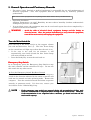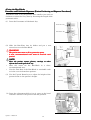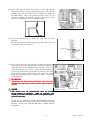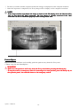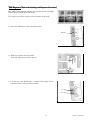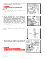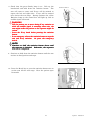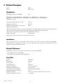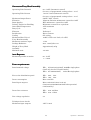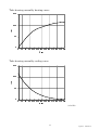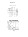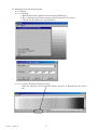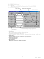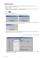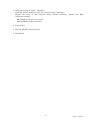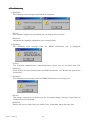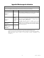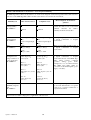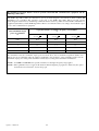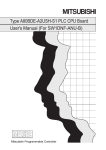
1
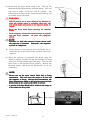
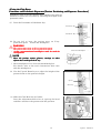
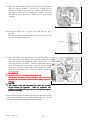
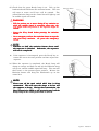
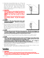
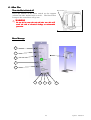
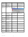
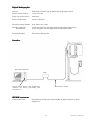
Panorama XX-ray Unit
Veraview ICIC-5
Operation Instructions
Contents
Page
1.
Warnings and Notes for Safe Operation .................................................................................... 4
2.
Overview and Parts Identification ............................................................................................. 7
1) Parts Identification .................................................................................................................. 7
2) Operation Panel and Control Box Description ...................................................................... 8
3.
Installation................................................................................................................................... 9
4.
Getting Ready .............................................................................................................................. 9
Panorama Operation Check ..................................................................................................... 10
5.
General Operation and Cautionary Remarks ......................................................................... 11
Turn the Main Switch On ......................................................................................................... 11
Panorama and Pedodontic Exposures [Patient Positioning and Exposure Porcedures] ................... 12
Patient Egress ........................................................................................................................... 18
TMJ Exposure [Patient Positioning and Exposure Procedure] ............................................. 19
Patient Egress ........................................................................................................................... 22
6.
After Use .................................................................................................................................... 23
Turn the Main Switch off .......................................................................................................... 23
7.
Regular maintenance ................................................................................................................ 25
(1) Cleaning .............................................................................................................................. 25
(2) Verification of Automatic Exposure Control ..................................................................... 25
8.
Inspection ................................................................................................................................... 26
(1) Regular Inspection ............................................................................................................. 26
(2) Repair .................................................................................................................................. 27
9.
Technical Description ................................................................................................................ 28
10. Replacement Parts .................................................................................................................... 40
IC5 DDAE Verification Procedure .................................................................................................. 41
1
Operation
2005-10-21
Thank you for purchasing the Veraview IC-5 Super High Speed, a direct current, dental panoramic
X-ray apparatus.
For optimum safety and performance, read this manual thoroughly before using the unit and pay
close attention to the warnings and notes.Keep this manual in a handy place for ready reference.
* ATTENTION
The J. Morita Mfg. Corp. will not be responsible for accidents, instrument damage, or bodily
injury resulting from
1. repairs made by personnel not authorized by the J. Morita Mfg. Corp.
2. any changes, modifications, or alterations of its products
3. the use of products or instrument made by other manufacturers, except for those procured
by the J. Morita Mfg. Corp.
4. maintenance or repairs using parts or components other than those specified by the J.
Morita Mfg. Corp. and other than in their original condition
5. operating the instrument in ways other than the operating procedures described in this
manual or resulting from the safety precautions and warnings in this manual not being
observed
6. workplace conditions and environment or installation conditions which do not conform to
those stated in this manual such as improper electrical power supply
7. fires, earthquakes, floods, lightning, natural disasters, or acts of God
The J. Morita Mfg. Corp. will supply replacement parts and be able to repair the product for a
period of 10 years after the manufacture of the product has been discontinued.
*
*
The user (i.e., clinic, hospital etc.) must perform the inspection procedures specified in the Regular
Inspection Check List every six months.
Parts must be replaced periodically as necessary. The Regular Inspection Check List includes
replacement parts.
Caution: Federal law restricts this device to sale by or on the order of a dentist (for U.S.A.).
U.S.A.).
Operation 2006-09-21
2
SAFETY / WARNINGS / PRECAUTIONS
The majority of operational and electro-mechanical problems are the result of not following the
instructions and maintenance as presented in this manual. Please operate and maintain the
equipment in accordance with the manufacturer‘s recommendations.
The equipment should be operated in accordance with this manual to avoid damage to the equipment
or potential bodily harm to the patient and / or operator.
The owner / user is the party responsible for the proper operation and maintenance of the (medical
device) equipment.
This is a medical device and must be operated by dentists and other properly licensed personnel.
This equipment is designed as a dental diagnostic device - Do not use this equipment for other
non-designated purposes.
When using this operation manual please make special note of the meaning and follow the
instructions and symbols used for warnings, radiation symbols, notes to utilize the Veraview IC-5 in a
correct and safe manner for both the operators‘ and the patients’.
Note the meaning of the following symbols and expressions:
WARNING
This warns of the possibility of bodily injury to the patient or a health
hazard.
NOTE
This alerts the user to the possiblity of damage to the equipment or
important points concerning operation and performance.
3
Operation
2005-05-23
1. Warnings and Notes for Safe Operation
WARNING
• This X
X--ray unit may be dangerous to PATIENT and OPERATOR unless safe exposure factors
and operating instructions are observed.
• Only dentists and other legally qualified and authorized personnel are allowed to operate this
•
•
•
•
•
•
•
•
•
•
•
•
equipment.
MEDICAL ELECTRICAL EQUIPMENT needs special precautions regarding EMC and needs to
put
ut into service according to the EMC information provided in the
be installed and p
ACCOMPANYING DOCUMENTS.
Portable and mobile RF communications equipment can affect MEDICAL ELECTRICAL
EQIPMENT.
may
Use of parts other than those accompanied or specified by J.Morita Mfg. Corp. m
ay result in
increasd EMC emissions or decreased EMC immunity of the EQUIPMENT.
The EQUIPMENT should not be used adjacent to or stacked with other equipment and that if
adjacent or stacked use is necessary, the EQUIPMENT should be observed to verify normal
operation in the configuration in which it will be used.
X--ray shielded room providing 20dB attenuation or higher against
This unit is only for use in an X
electromagnetic radiation over the range 30MHz to 1GHz.
Do not use this unit for patients who have a pacemaker; the pacemaker could malfunction or
operate in an abnormal or random way.
Do not use this unit for fluoroscopic examinations.
Do not use this unit for women who are or might be pregnant.
Do not use the wireless transmission devices listed below iin
n the examination area;
electromagnetic interference from these devices could cause the Veraview ICIC-5 to operate in a
random, unexpected and dangerous manner.
1. Cell phone terminals
2. Wireless transmitting devices such as ham radios, walkietransceivers
walkie-talkies, and transc
eivers
3. Cell phones
4. Routers for intra
intra--building paging systems, wireless LAN cordless, analogue telephones, and
other electric wireless devices
Interference from the devices listed below could cause the unit to operate in a random,
manner.
X--ray examination booth,
unexpected and dangerous m
anner. They should not be placed in the X
or they should be turned off whenever the unit is being used.
1. Electric medical devices for examination, diagnosis and treatment.
2. Personal computers
X--ray sh
shield
The Unit must be installed in an X
ield location.
Local regulation for radiation protection must be observed.
X--ray booth or other
If the unit is not enclosed by an X
protective barrier, everyone except the patient must stay
X--ray
outside the area shown in the illustration during X
emission.
X--ray protection area should consist of a wall, floor and
The X
ceiling with a minimum of 1.5 mm lead shielding or its
equivalent and should have glass windows with a minimum
of 1.5 mm lead shielding or its equivalent, through which the
operator can obverve the patient. A sign should clearly
X--ray protection area, and a caution
identify the area as an X
X--ray emission. Observe local
sign should light up during X
regulations.
Operation 2006-09-21
4
WARNING
• The
•
•
•
•
•
•
•
•
•
•
•
•
•
•
•
•
•
•
•
X--ray protection gear such as
patient must be provided with appropriate X
lead--impregnated clothing that conforms to local regulations.
lead
The operator must be able to see the exposure emissions lights and hear the audible signal
during operation of the equipment.
The operator must be able to see and hear the patient during the operation
operation of the equipment.
Proper radiation safety precautions must be established in accordance with local, state and
governmental regulations in regards to operator and patient protection. The ultimate
ensure
responsibility lies with the owner/operator to ensu
re that the protection requirements of
national and local codes are met.
Proper infection control procedures must be established and maintained for each patient.
X--ray dosage
Focal Spot and Skin Distance should be as great as possible to keep the absorbed X
as low as reasonably achievable.
Do not leave anything within the movement area of the arm, lift and patient frame.
Avoid the risks of electrical shock, equipment damage and fire during an electrical storm:
equipment,
Have the patient immediately go away from the eq
uipment, turn off the main switch, and
11
unplug the equipment. (See page 1
1.)
X--ray protection apron. (See pages 12, 15 and 20
20.)
The patient must wear an X
.)
new,, uncontaminated cover must be used for each patient. (See page 1
12
A new
2.)
The beams are lasers that ccould
ould injure the eyes; never look directly into them or allow them to
13
strike anyone in the eye. (See page 1
3.)
A new, uncontaminated mouthpiece must be used for each patient. (See page 1
15
5.)
beams..
A Class 2 laser is used for positioning beams
beams
ams are lasers that could injure the eyes; never look directly into them or
The positioning be
16
20.)
allow them to strike anyone in the eye. (See pages 1
6 and 20
.)
X--ray emission or while the audible signal is sounding;
Tell the patient not to move during X
mightt strike the patient or the exposure might be ruined. (See pages 14,
other wise, the arm migh
22.)
17, 21 and 22
.)
X--ray booth before pressing the emission button. (See pages 14, 17, 21 and 22
22.)
Leave the X
.)
X--ray emission. Or press
In an emergency release the emission button to stop the arm and X
22.)
the emergency switch. (See pages 14, 17, 21 and 22
.)
X--ray unit before pressing the Ready key.
Make sure the patient is well away from the X
18
22.)
(See pages 1
8 and 22
.)
To stop the arm in an emergency when it is returning to its start position, press
press the Ready key
on the operation panel, the emission button or the emergency switch. (See pages 1
17
22.)
7 and 22
.)
Do not fail to turn the unit off after use; this will avoid the risk of electrical leakage or
23.)
unintended operation. (See page 23
.)
Always turn off the main switch before disinfecting outer surfaces. Otherwise there is a risk
of electrical shock and burns as well as the possibility of accidents due to the accidental
25
pressing of switches or keys. (See page 2
5.)
5
Operation 2006-09-21
NOTE
• If an “X” appears above the icon in the customized tool bar, check the cable connections for the
•
•
•
•
•
•
•
•
•
•
•
•
•
•
Ethernet.. (See page 1
10
HUB and Ethernet
0.).
If the emergency stop switch was pressed during the transmission of data, wait unitl the
transmission is completed before turning off the main switch.
switch. However, if the transmission is
11
not completed after 3 minutes, go ahead and turn off the main switch anyway. (See page 1
1.)
X--ray. (See
Have the patient remove glasses, earrings or other objects that could spoil the X
20.)
pages 12, 15 and 20
.)
The beams tturn
urn off automatically after 60 seconds except during an exposure. After an
exposure, the beams go out after the arm rotates to the patient egress position and stops. (See
13
16.)
page 1
3 and 16
.)
finished.
Continue to hold the emission button down until the exposure is fi
nished. Otherwise, the
21,, and 22
22.)
exposure will not be completed. (See pages 14, 17, 21
.)
Never turn off the main switch while data is being transmitted. This will cause the image to be
lost and the computer to freeze. During data transmission, the Data Transmission
Transmission LEDs on
the operation panel and the Ready lamp on the control panel flash on and off. (See pages 14,
22.)
17 and 22
.)
Bite--Block will be visible in the image as it lies within the XA portion of the Bite
X-ray field. (See page
14.)
tops before the image is shown on the PC display, leave the Veraview ICIf the image transfer sstops
IC-5
unit on and check the LAN connection. The last image is possibly retrieved if the LAN
re--established properly before turning off the unit. (See pages 1
18
22.)
connection can be re
8 and 22
.)
alkaline,, acidic cleaning solutions, cresol liquid soap, or
Do not soak in disinfecting alcohol or alkaline
other types of chemicals. Doing so can lead to deformation and other damage to the Bite Block
Plate.. (See page 2
25
and Plate
5.)
Avoid discoloration and other damage to the outer surfaces and the seat; do not use alkaline or
acidic cleaning solutions, cresol liquid soap, or other types of chemicals. Use only ethanol or a
25
neutral detergent. (See page 2
5.)
surface
If a chemical solution is accidentally spilled on the outer su
rface or the seat, use ethanol to
25
immediately wipe it off. (See page 2
5.)
The values displayed in dialog (1) are not saved. Ensure that the values are recorded before
39.)
pressing the OK button. (See page 39
.)
dialog
39.)
No further exposures can be made until this dia
log is closed. (See page 39
.)
In TMJ exposure mode, for each exposure (mouth opened and mouth closed) dialog (1) will be
Dose--Area
Area--Products. (See page 39
39..)
displayed. Be sure to add the resulting Dose
LAN
Be careful not to trip over the LAN cable. It may damage the LA
N connectors, communication
circuit and/or the PC.
Operation 2006-09-21
6
2. Overview and Parts Identification
1) Parts Identification
Lift
Arm
Emergency Stop Switch
Head Stabilizer
Elevation
Motor Unit
Main Power Switch
X Ray Head
Operation Panel
X Ray CCD Sensor Unit
Frankfurt Beam
Adjustment Dial
Bite-Block, Chin Rest or
Lip-nose Rest
Adjustment Dial for Bite-Block,
Chin Rest and Lip-nose Rest
Patient Handle
Patient Frame
Support Column
Base
7
Operation 2006-09-21
1) Panorama Key Green lamp lights up when set
Operation Panel
2) Operation Panel and Control Box Description
Green lamp lights up when set
3) Pedodontic Key
Green lamp lights up when set
2) TMJ Key
4) Up Key Hold down to raise lift
Lights up when lift is moving
Goes out when lift stops
5) Down Key Hold down to lower lift
Lights up when lift is moving
Goes out when lift stops
8
Operation 2006-09-21
Hand Switch
Emission Button
Key Switch (Option)
Turn the key off to disable the Emission Button.
Take the key out to prevent unauthorized use.
This also prevents any accidental use of the
Emission Button.
12) Power Lamp:Blue: Power On
Flashing Blue: Auto Power Off
8) Data Transmission Status Indicator Confirms Transmission Status
Lights up green when unit is ready to make an exposure
Flashes orange during data transmission
Flashes red to indicate transmission failure
7) Beam On and Off Key: Press to turn the beams
on and off
Lights up green when beams are on.
Lamp is off when beams are off.
11) Ready Lamp:
Green: Ready for exposure
Flashing Green: Ready for transmission
but not for exposure.
6) Ready Key Press to set unit for exposure
Flashing Orange: Data Transmission
Green when unit is ready to make an exposure
Flashing Red: Data Transmission Failure
Otherwise, it may be out or flashing green
9) Data Transmission Indicator: Flashes while data is
being transmitted.
Control Box
10) Emission Lamp Light up yellow during x ray emission.
3. Installation
* Refer to the separate installation manual.
Other systems (PC, monitor, etc.) are necessary for this unit for image acquisition, display and
preservation.
For computer system requirements refer to the section titled “Requirements for Computers and
their Peripheral Devices” in part 9. Technical Discription.
4. Getting Ready
*
PC Set Up (Refer to the user’s manual for i-Dixel,
the Digora for Windows or other application.)
Make a patient folder or open an existing one.
Turn the PC and HUB on and start the application
software. Then turn on the Veraview IC-5.
The Veraview IC-5 checks the PC connection
through the application software when it starts. An
error will be reported if the application software is
not open for capturing images when the Veraview
IC-5 is turned on. Restart the Veraview IC-5 after
starting the application software if a communication
error occurs when it is turned on.
*
Select the radiographic resolution
The computer is used to set the resolution (speed)
for the IC-5.
Standard resolution (Super high speed radiographic mode)
High resolution (High speed radiographic mode)
1. Check resolution
Place the cursor on the icon in the
customized tool bar to check the
resolution.
Cursor
9
Operation 2006-09-21
2. Change Resolution
To change the resolution, click the icon
in the customized tool bar.
Icons for Standard (192um) and High
Resolution (144um) will be displayed.
Check the desired resolution.
Icons
High
Standard
Icon
NOTE
• If an “X” appears above the icon in the
customized tool bar, check the cable
Ethernet.
connections for the HUB and Ethe
rnet.
To test the arm rotation without emitting
any X-rays, right-click the icon and select
“No X-ray”.
Panorama Operation Check
Turn the main switch on and press the Ready key. Then hold the emission button down.
Check that the arm starts to rotate, X-rays are emitted, the yellow emission lamp lights up and
the audible signals sounds. Check that X-ray emission and arm rotation stop after the
irradiation time is up. Press the emission button again to return the arm to its starting
position.
* If the emergency switch has been accidentally pressed during cleaning or for some other
reason, the arm will not rotate and X-rays will not be emitted. In this case, turn the
emergency switch in the direction indicated by the arrow to restore normal operation.
Operation 2006-09-21
10
5. General Operation and Cautionary Remarks
*
The owner (clinic, hospital or medical institution) is responsible for use and matintenance of
mediacal equipment. Also, this equipment must be operated only by medically qualified
professionals.
Do not use this equipment for anything other than dental X-ray examinations.
*
*
Operation Conditions
Ambient Temperature: 10~35°C; Humidity: 20~90% relative humidity (without condensation);
Atmospheric pressure: 70~106kPa
If an accident occurs, the equipment must not be used until repairs have been completed by a
qualified and trained technician.
WARNING • Avoid the risks of electrical shock, equipment damage and fire during an
electrical storm: Have the patient immediately go away from the equipment,
turn off the main switch, and unplug the equipment.
Turn the Main Switch On
Press the top of the main switch on the support column
[the side marked with a line (|)]. The blue Power Lamp
on the control box will light up to show that the unit is on.
*
*
If the unit is not used for 30 minutes, it will
automatically turn itself off and the blue Power Lamp
will start to blink on and off.
Main Switch
Press the Ready Key to turn the unit back on.
Emergency Stop Switch
In an emergency, press the Emergency Stop Switch to stop
the arm’s rotation and the emission of X-rays. Do not use
this switch for any other reason.
In Case the Emergency Switch Has Been Pressed
Turn the main switch off and then turn the emergency
switch in the direction indicated by the arrow to put the unit
back into its normal and safe operating mode. Restart the
computer. Turn the unit back on and check that it operates
normaly in panorama mode. If it does not, contact your
local dealer or the J. Morita Mfg. Corp.
NOTE
Emergency Stop Switch
• If the emergency stop switch was pressed during the transmission of data, wait
completed
unitl the transmission is complet
ed before turning off the main switch. However,
if the transmission is not completed after 3 minutes, go ahead and turn off the
main switch anyway.
11
Operation 2006-09-21
<Using the BiteBite-Block>
Block>
Panorama and Pedodontic Exposures [Patient Positioning and Exposure Porcedures]
Porcedures]
Pedodontic mode is for the patients have smaller jaws such as
children to reduce the X-ray dose by shortning the length of the
panoramic orbit.
(1) Press the Panorama or Pedodontic key.
Panorama Key
Pedodontic Key
(2) Slide the Bite-Plate into its holder and put a new,
unused cover on the Bite-Block.
WARNING
Bite-Block Cover
Bite-Block
• The patient must wear an X-ray protection apron.
• A new, uncontaminated cover must be used for each
patient.
Bite-Plate
NOTE
• Have the patient remove glasses, earrings or other
objects that could spoil the X-ray.
∗
∗
Store the covers for the Bite-Block in a clean,
uncontaminated area.
Use the Chin Rest if the Bite-Block is unsuitable such
as in the case of edentulous patients.
(3) Use the Up and Down keys to adjust the height of the
patient frame to the patient’s height.
Up key
Down key
(4) Press the adjustment dial to free it, open up the head
stabilizer and have the patient take his position.
Head Stabilizer
Adjustment Dial
Operation 2006-09-21
12
(5) Have the patient light bite down on the Bite-Block,
(incisal occlusion.), rest his chin on the plate, and grip the
handles. Use the Up or Down key to adjust the height of
the Bite-Block. Have the patient pull his chin in and
stand as straight as possible. Observe the patient from
the rear to make sure he is standing straight.
Bite-Block
Bite-Plate
Patient
Handle
(6) Press the Ready key to move the arm into its start
position.
The Ready lamp will light up green to show that the unit
is ready to make an exposure.
Ready Key
(7) Press the Beam On and Off key to turn the beams on.
Line up the patient’s sagital plane with the sagital beam.
Turn the dial for the frankfurt plane beam to line it up
with the patient’s ear orifice. Turn the adjustment dial
Sagittal Beam
to move it backwards or forwards and line up the image
layer beam with the distal edge of the upper left canine.
Frankfurt Beam Dial
Press the adjustment dial to lock it in place. Close the
Up
head stabilizer.
Frankfurt Beam
Image Layer Beam
WARNING
• The beams are lasers that could injure the eyes; never
look directly into them or allow them to strike anyone in
the eye.
NOTE
Down
Back
Front
Beam on and off key
Adjustment Dial
• The beams turn off automatically after 60 seconds
except during an exposure. After an exposure, the
beams go out after the arm rotates to the patient egress
position and stops.
*
It may not be possible to release the Bite-Block when the
patient has his chin resting on the plate even after pressing
the dial. In this case, push the Bite-Plate slightly towards
the patient.
13
Operation 2006-09-21
(8) Check that the green Ready lamp is on. Pick up the
handswitch and hold down the emission button. The arm
will start to rotate and X-rays will be emitted. The
yellow Emission lamp on the control box will light up and
an audible signal will sound.
WARNING
•Tell the patient
during
not to move du
ring X-ray emission or
while the audible signal is sounding; other wise, the
arm might strike the patient or the exposure might be
ruined.
• Leave the X
X--ray booth before pressing the emission
button.
• In an emergency release the emission button to stop the
the
X--ray emission. Or press the emergency
arm and X
switch.
NOTE
NOTE
• Continue to hold the emission button down until
the exposure is finished.
will not be completed.
*
Otherwise, the exposure
If the exposure is interrupted, press the Ready key to
return the arm to its start position and then repeat the
exposure.
(9) When the exposure is completed, the Ready lamp will
change to orange and flash on and off, the Emission lamp
will go out, and the audible signal will stop. The arm will
then rotate to the patient egress position. Release the
Emission button and hang the handswitch up on the
control box.
NOTE
• Never turn off the main switch while data is being
transmitted. This will cause the image to be lost and
transmission,
the computer to freeze. During data tra
nsmission, the
Data Transmission LEDs on the operation panel and the
Ready lamp on the control panel flash on and off.
• A portion of the Bite
Bite--Block will be visible in the image as
X--ray field.
it lies within the X
Operation 2006-09-21
14
Emission Button
<Using the Chin Rest>
Rest>
Panorama and
and Pedodontic Exposures [Patient Positioning and Exposure Porcedures]
Pedodontic mode is for the patients have smaller jaws such as
children to reduce the X-ray dose by shortning the length of the
panoramic orbit.
(1) Press the Panorama or Pedodontic key.
Panorama Key
Pedodontic Key
(2) Do not fail to have the patient wear an X-ray
protection apron. Center the mouthpiece.
WARNING
• The patient must wear an X-ray protection apron.
• A new, uncontaminated mouthpiece must be used for
Center the Mouthpiece
each patient.
NOTE
• Have the patient remove glasses, earrings or other
objects that could spoil the X-ray.
* Store mouthpieces in a clean uncontaminted place.
For details, refer to the user’s instructions that come
with the mouthpieces.
(3) Use the Up and Down keys to adjust the height of the
patient frame to the patient’s height.
Up key
Down key
(4) Slide the Chin Rest into its holder.
Press the adjustment dial to free it, open up the head
stabilizer and have the patient take his position.
Head Stabilizer
Adjustment Dial
15
Operation 2006-09-21
(5) Have the patient put his chin on the chin rest and lightly
grip the patient handles. Use the Up or Down key to
adjust the height of the chin rest. Have the patient pull
his chin in and stand as straight as possible. Observe
the patient from the rear to make sure he is standing
straight.
Chin Rest
Patient Handle
(6) Press the Ready key to move the arm into its start
position.
The Ready lamp will light up green to show that the unit
is ready to make an exposure.
Ready Key
(7) Press the Beam On and Off key to turn the beams on.
Line up the patient’s sagital plane with the sagital beam.
Turn the dial for the frankfurt plane beam to line it up
Sagittal Beam
with the patient’s ear orifice. Turn the adjustment dial to
move it backwards or forwards and line up the imageFrankfurt Beam Dial
layer beam with the distal edge of the upper left canine.
Press the adjustment dial to lock it in place. Close the
head stabilizer.
Frankfurt Beam
Up
Down
WARNING
• A Class 2 laser is used for positioning beams
beams..
The beams are lasers that could injure the eyes; never
look directly into them or allow them to strike anyone in
the eye.
NOTE
• The beams turn off automatically after 60 seconds
except during an exposure. After an exposure, the
beams go out after the arm rotates to the patient egress
position and stops.
* It may not be possible to release the chin rest when the patient
has his chin resting on it even after pressing the dial. In this
case, push the chin rest slightly towards the patient.
Operation 2006-09-21
16
Image Layer Beam
Back
Front
Beam on and off key
Adjustment Dial
(8) Check that the green Ready lamp is on. Pick up the
handswitch and hold down the emission button. The arm
will start to rotate and X-rays will be emitted. The
yellow Emission lamp on the control box will light up and
an audible signal will sound.
Emission Button
WARNING
• Tell the patient
not to move during X-ray emission or
while the audible signal is sounding; other wise, the
arm might strike the patient or the exposure might be
ruined.
• Leave the X-ray booth before pressin
pressing
g the emission
button.
• In an emergency release the emission button to stop the
arm and X-ray emission. Or press the emergency
switch.
NOTE
NOTE
• Continue to hold the emission button down until
the exposure is finished.
will not be completed.
*
Otherwise, the exposure
If the exposure is interrupted, press the Ready key to
return the arm to its start position and then repeat the
exposure.
(9) When the exposure is completed, the Ready lamp will
change to orange and flash on and off, the Emission lamp
will go out, and the audible signal will stop. The arm will
then rotate to the patient egress position. Release the
Emission button and hang the handswitch up on the
control box.
NOTE
• Never turn off the main switch while data is being
This
transmitted. T
his will cause the image to be lost and
the computer to freeze. During data transmission, the
Data Transmission LEDs on the operation panel and the
Ready lamp on the control panel flash on and off.
17
Operation 2006-09-21
*
*
Do not try to make another exposure before the image is displayed on the computer monitor.
After the exposure is completed, the X-ray image will be display on the computer’s monitor.
NOTE
• If the image transfer stops before the image is shown on the PC display, leave the Veraview IC
IC--5
and
unit on a
nd check the LAN connection. The last image is possibly retrieved if the LAN
re--established properly before turning off the unit.
connection can be re
Patient Egress
Release the head stabilizer and carefully guide the patient away from the X-ray unit.
* Throw away the used mouthpiece.
WARNING
• Make sure the patient is well away from the X-ray unit before pressing the Ready key.
• To stop the arm in an emergency when it is returning to its start position, press the Ready key on
the operation panel, the emission button or the emergency switch.
Operation 2006-09-21
18
TMJ Exposure [Patient Positioning and Exposure Procedure]
Procedure]
This makes four separate images, one each for the left and right
sides with the mouth open and closed.
The entire procedure requires two rotations of the arm.
1. Press the TMJ key on the operation panel.
TMJ Key
2. Slide the lip-nose into its holder.
Press the adjustment dial to free it.
Lip-nose Rest
Adjustment Dial
3. Use the Up and Down keys to adjust the height of the
patient frame to the patient’s height.
Up Key
Down Key
19
Operation 2006-09-21
4. Put an X-ray protection apron on the patient, have him get
into position and loosely set the head stabilizer.
WARNING
• The patient must wear an X-ray protection apron.
Head Stabilizer
NOTE
• Have the patient remove glasses, earrings or othe
otherr
Lip-nose Rest
ray..
objects that could spoil the X-ray
5. Turn the adjustment dial to move the lip-nose rest
backwards or forwards until it is lined up with the blue
mark; then press the adjustment dial to lock it in place.
Have the patient put his lip against the lip-nose rest and
lightly grip the patient handles. Use the Up or Down
key to adjust the height of the lip-nose positioner. Have
the patient pull his chin in and stand as straight as
possible. Observe the patient from the rear to make sure
he is standing straight.
Lip-nose rest
Adjustment Dial
Blue Mark
Patient Handle
6. Press the Ready key to move the arm into its start
position.
Ready Key
7. Have the patient close his mouth. Press the Beam On
and Off key to turn the beams on. Line up the patient’s
sagital plane with the sagital beam. Turn the dial for
the eye-ear plane beam to line it up with the patient’s ear
orifice. Close the head stabilizer.
* The image layer beam does not light up.
WARNING
Up
Down
• A Class 2 laser is used for positioning beams
beams..
The beams are lasers that could injure the eyes; never
look
ok directly into them or allow them to strike anyone in
lo
the eye.
Operation 2006-09-21
Frankfurt Plane Beam
Sagittal Beam
20
Beam On and Off key
Frankfurt Beam Dial
8. Check that the green Ready lamp is on. Pick up the
handswitch and hold down the emission button. The
arm will start to rotate and X-rays will be emitted to
expose the left and right sides. X-rays will be emitted
twice before the arm stops. During emission the yellow
Emission lamp on the control box will light up and an
audible signal will sound.
Emission Button
WARNING
• Tell the patient not to move during X-ray emission or
signal
while the audible sign
al is sounding; other wise, the
arm might strike the patient or the exposure might be
ruined.
• Leave the X-ray booth before pressing the emission
button.
• In an emergency release the emission button to stop the
emergency
arm and X-ray emission. Or press the emerg
ency
switch.
NOTE
• Continue to hold the emission button down until
the exposure is finished.
will not be completed.
Otherwise, the exposure
9. Continue to hold down the emission button until the arm
reaches its final position and stops.
10. Press the Ready key or press the emission button once to
set the arm for the next stage. Have the patient open
his mouth.
21
Operation 2006-09-21
11. Check that the green Ready lamp is on. Pick up the
handswitch and hold down the emission button. The arm
will start to rotate and X-rays will be emitted to expose
the left and right sides. X-rays will be emitted twice
before the arm stops.
During emission the yellow
Emission lamp on the control box will light up and an
audible signal will sound.
Emission Button
WARNING
• Tell the patient not to move during X-ray emission or
wise,
while the audible signal is sounding; other wi
se, the
arm might strike the patient or the exposure might be
ruined.
• Leave the X-ray booth before pressing the emission
button.
• In an emergency release the emission button to stop the
arm and X-ray emission. Or press the emergency
switch.
NOTE
• Continue to hold the emission button down until
the exposure is finished.
will not be completed.
Otherwise, the exposure
12. When the entire exposure series is completed, the Ready
lamp will change to orange and flash on and off, the
Emission lamp will go out, and the audible signal will stop.
The arm will then rotate to the patient egress position.
Release the emission button and hang the handswitch up
on the control box.
NOTE
• Never turn off the main switch while data is being transmitted. This wi
will
ll cause the image to be
lost and the computer to freeze. During data transmission, the Data Transmission LEDs on the
operation panel and the Ready lamp on the control panel flash on and off.
* Do not try to make another exposure before the image is displayed on the computer monitor.
* After the exposure is completed, the X-ray image will be display on the computer’s monitor.
NOTE
• If the image transfer stops before the image is shown on the PC display, leave the Veraview ICIC-5
unit on and check the LAN connection. The last image is possibly retrieved if the LAN
re--established properly before turning off the unit.
connection can be re
*
*
*
It takes longer to readread-in an image if an image window is already open. Also, if a Digora is
connected, it will take longer
longer to readread-in the image if the Digora is not turned on.
Density compensation is automatically applied to digital images, but in cases where the image is
unusually dark, this can result in a whitish or milky image.
Seam visible in enlarged images
This seam is not visible in the image as it appears at first, but if the image is enlarged, a seam
appears in the middle. This is where the two CCD sensors are joined.
Patient Egress
Release the head stabilizer and carefully guide the patient away from the X-ray unit.
WARNING
• Make sure the patient is well away from the X-ray unit before pressing the Ready key.
• To stop the arm in an emergency when it is returning to its start position, press the Ready key
on the operation panel, the emission button or tthe
he emergency switch.
Operation 2006-09-21
22
6. After Use
Use
Turn the Main Switch off
Main Switch
Press the bottom of the main switch on the support
column (the side marked with a circle). The blue Power
Lamp on the control box will go out.
WARNING
use;
• Do not fail to turn the unit off after us
e; this will
avoid the risk of electrical leakage or unintended
operation.
Error Message
1
2
3
4
5
6
7
8
9
23
10
Operation 2006-09-21
Error
Current Overlaod
for Lift Motor
Arm Motor
Malfunction
Analog power
supply failure for
digital cassette
Transmission
Error
Interlock
Excessive
current, primary
side
Excessive
feedback for
secondary side of
tube voltage and
current
Tube heater drive
malfunction
Overheated head
Malfunction of
tube voltage
feedback line
Malfunction of
tube current
feedback
Exposure timing
malfunction
Overheating of
FET on Board B
Indication or Message
Operation Keys 4 and
5 blink
simultaneously
Operation Keys 1, 2
and 3 blink
simultaneously
Error message
appears in computer
monitor
Restoration Method
Press operation key 4
or 5.
Restart DixelD and
turn the IC-5 off and
back on again.
Check the connection for
the interface cable
Opertion keys 6, 7, 8
and 9 blink
simulataneously.
Also operation key 10
turns red and blinks.
Operation Keys 1, 2
and 3 blink
simultaneously
Operation Keys 1, 2
and 3 blink
simultaneously
Operation Keys 1, 2
and 3 blink
simultaneously
Restart DixelD and
turn the IC-5 off and
back on again.
Check the connection for
the interface cable
Operation Keys 1, 2
and 3 blink
simultaneously
Operation Keys 1, 2
and 3 blink
simultaneously
Operation Keys 1, 2
and 3 blink
simultaneously
Operation Keys 1, 2
and 3 blink
simultaneously
Operation Keys 1, 2
and 3 blink
simultaneously
Operation Keys 1, 2
and 3 blink
simultaneously
Press operation key 1,
2 or 3.
Press operation key 1,
2 or 3.
Reference
Find out if patient was
pushing or pulling on the
lift.
Find out if the patient was
touching the arm.
Press operation key 1,
2 or 3.
Press operation key 1,
2 or 3.
Press operation key 1,
2 or 3.
Press operation key 1,
2 or 3.
Wait a little while before
restoring normal operation
Press operation key 1,
2 or 3.
Press operation key 1,
2 or 3.
Press operation key 1,
2 or 3.
Press operation key 1,
2 or 3.
Wait a little while before
restoring normal operation
Contact your local dealer if the unit cannot be restored to normal operating condition using the above
porcedures.
Operation 2006-09-21
24
7. Regular maintenance
maintenance
(1)
Cleaning
Cleaning
ing
Between patients, disinfect the Head Stabilizers, the Bite Block and Plate, the Chin Rest, the
Lip-nose Rest and the patient handles by wiping them with disinfecting alcohol.
Once a day, wipe the operation panel with disinfecting alcohol.
Grease the wire cables for the lift once every six months.
WARNING
• Always turn off the main switch before disinfecting outer surfaces.
Otherwise
Otherwi
se there is a risk
of electrical shock and burns as well as the possibility of accidents due to the accidental
pressing of switches or keys.
NOTE
• Avoid discoloration and other damage to the outer surfaces and the seat; do not use alkaline or
cleaning
aning solutions, cresol liquid soap, or other types of chemicals.
acidic cle
• If a chemical solution is accidentally spilled on the outer surface or the seat, use disinfecting
ethanol to immediately wipe it off.
(2)
Verification of Automatic Exposure Control
Read the section titled “IC5 DDAE Verification Procedure” (page 41) for the verification method
of the automatic exposure control.
25
Operation 2006-09-21
8. Inspection
*
The user (hospital, medical institute or clinic) is responsible for inspection and maintenance of medical
devices.
(1) Regular Inspection
Have the following inspection and maintenance procedures performed. In some countries such
as Germany, the law requires an annual inspection which is specified by the manufacturer. We
recommend that the following inspections be performed even if not required by law.
The Veraview IC-5 should be inspected for all the items in the following list once every year.
The inspection may be performed only by
• the technicians of J. Morita’s subsidiaries all over the world.
• technicians employed by authorized J. Morita dealers and specially trained by J. Morita.
• independent technicians specially trained and authorized by J. Morita.
Power Supply and Physical Stability
1. Measure the unit’s power supply.
Use a digital or analog tester to measure the unit’s power supply. The result must be rated
nominal Voltage ±10%.
2. Check ground connection.
Visually inspection the ground connection to make sure it is securely and properly connected.
3. Floor and base securing bolts.
Visually inspect the floor and base securing bolts. Check that the floor is level and make sure the
base bolts have not loosened up.
4. Bolt and screw tightness
Inspect all the bolts and screws on the unit. Make sure that all bolts are in place and properly
secured.
5. Internal electrical circuitry
Inspect all the printed circuit boards and the wiring connecting electrical components and
elements. Make sure all wiring and connections are intact.
Panoramic Exposure Inspection
1. X-ray Slit
Make sure the X-ray beam passes through the secondary slit for the digital cassette.
2. Arm rotation movement
Press the emission button and make sure the arm rotates properly without abnormal noise or
slippage and stops in the specified position. Repeat this test 3 times.
3. Emergency Stop
Release the emission button when the arm is in the middle of its rotation pattern. The arm must
stop when the button is released.
4. Head stabilizer
Make sure the head stabilizer open and close properly.
5. Chinrest
6. Light Beams
Check the Mid-sagittal Plane, Frankfurt Plane, and Image Layer Light Beams.
7. Operation panel and control box.
Check that all the keys on the operation panel work. Make sure the display on the operation
panel and the control box all light up properly.
Operation 2006-09-21
26
Lift Mechanism
1. Vertical Motion
Press the up and down keys.
times.
Make sure the lift moves smoothly and stops properly.
Repeat this 3
2. Wire Cables
Check the wire cables for broken strands. Make sure the ends are properly secured.
cables once every six months with the grease provided by the manufacturer
(2)
Grease the
Repair
* ATTENTION
1. The J. Morita Mfg. Corp. will not be responsible for accidents, equipment damage, or bodily
injury resulting from repairs made by personnel not authorized by the J. Morita Mfg. Corp.
2. The J. Morita Mfg. Corp. will not be responsible for accidents, equipment damage, or bodily
injury resulting from any changes, modifications, or alterations of its products.
3. The J. Morita Mfg. Corp. will not be responsible for accidents, equipment damage, or bodily
injury resulting from the use of products or equipment made by other manufacturers, except
for those procured by the J. Morita Mfg. Corp.
4. The J. Morita Mfg. Corp. will not be responsible for accidents, equipment damage, or bodily
injury resulting from maintenance or repairs using parts or components other than those
specified by the J. Morita Mfg. Corp. and in their original condition.
5. The J. Morita Mfg. Corp. will not be responsible for accidents, equipment damage, or bodily
injury resulting from operating the equipment in ways other than the operating procedures
described in this manual or resulting from not following the cautionary remarks and warnings
in this manual.
6. The J. Morita Mfg. Corp. will not be responsible for accidents, equipment damage, or bodily
injury resulting from workplace conditions and environment or installation conditions such as
improper electrical power supply which do not conform to those stated in this manual.
7. The J. Morita Mfg. Corp. will not be responsible for accidents, equipment damage, or bodily
injury resulting from fires, earthquakes, floods, lightning, natural disasters, or acts of God.
8. The J. Morita Mfg. Corp. will supply replacement parts and be able to repair the product for a
period of 10 years after the manufacture of the product has been discontinued.
*
For all repairs, contact your local dealer or the J. Morita Corp.
27
Operation 2006-09-21
9. Technical De
Description
Model
Type
XDP1
EX-1, EX-2
Classification
Europian Directive 93/42/EEC
IIb
Safety according to IEC 60601-1, IEC 60601-1-1, IEC 60601-1-2, IEC 60601-1-3,
IEC 60601-1-4. IEC 60601-2-7, IEC 60601-2-28 and IEC 60601-1-32 standards.
UL60601-1,C-UL.
Protection against electric shock
Degree of protection
Protection against ingress of liquids
Class I
Type B
IPX 0
Disinfection methods:
-Between patients, disinfect the Head Stabilizers, the Bite Block and Plate, the Chin Rest, the
Lip-nose Rest and the patient handles by wiping them with disinfecting alcohol.
-Once a day, wipe the operation panel with disinfecting alcohol.
Mode of operation
Intermittent
Applied part with no conductive connection to patient.
Intended use
The Veraview IC-5 is an extraoral source X-ray unit that is used for dental radiographic
examination and diagnosis of teeth, jaw, oral structure and TM-joints by exposing an X-ray
image receptor to ionizing radiation.
Essential Performance
Performance necessary to achieve freedom from unacceptable RISK.
- No unexpected X-ray irradiation
- No unexpected movement of the equipment
X-ray Tube
Model
Focal Spot
Target Angle
Target Material
Inherent Filtration
Muximuim Input Energy
Curcuit(Center-Grounded)
Maximum Filament Current
Filament Voltage
Filament Frequency Limits
Operation 2006-09-21
D-055SB
0.5 mm
12.5º
Tungsten
At least 1.0mmAl
635w (1 Sec.)
Constant Potential(DC)
3.0A
2.8 - 3.6V (At max. Filament Current 3.0A)
0 – 20 kHz
28
Generrator/X
Generrator/X-ray Head Assembly
Operating Tube Potential
Operating Tube Current
Maximum Output Power
Filtration
Beam Quality
Primary Protective Shielding
Outer Shell Temperature
Duty Cycle
Filament
Rectification
Cooling
Maximum Heat Unit of
X-ray Head Assembly
Maximum continues input
Leakage Radiation
Weight of X-ray Head
Assembly
Minimum mAs
60 ~ 70kV (Automatic control)
(accuracy of programmed setting values ± 10 %)
1 mA to 7.5mA (Automatic control)
(accuracy of programmed setting values ± 10 %)
525W ( 70kV, 7.5mA)
Inherent filtration minimum 2.5 mm Al at 70kV
HVL minimum 1.5 mm Al at 70kV
Minimum 0.5 mm Pb or equivalent
45ºC maximum
1:30
Preheated
Direct Current
Oil cooling
116kJ (1 HU=1.35 Joule, 1J=1Ws)
17.5w
max. 1.0mGy/h at 1m
Approximately 6 kg
4.8 mAs
Auto Exposure
Maximum possible excursion
60 - 70 kV
1 – 7.5mA
Power requirements
Rated nominal voltage
EX-1 AC100/110/115/120V, 50/60Hz single phase
(120V only for the US and Canada)
EX-2 AC 220/230/240V, 50/60 Hz single phase
Fuse at the distribution panel
EX-1 20A, slow
EX-2 16A, slow
Max. 0.85 kVA
Max.9.4/8.6/8.2/7.9/4.3/4.1/3.9A
(100/110/115/120/220/230/240Vwith operation)
0.5A(stand by)
Power consumption
Rated input amperes
Power line resistance
EX-1 max. 0.5Ohm
EX-2 max. 1 Ohm
Line voltage regulation
3%
Technique factor for the
Maximum input amperes
70kV 7.5mA
29
Operation 2006-09-21
Mechanical parameters
SID
SSD
Magnification
Weight
Main Unit
Control Box
Outer Dimensions
Main Unit
Control Box
Vertical Height of Focal Spot
Positioning Beams
Attenuation equivalent of
Head Stabilizer, Bite-Block and Chin Rest
520mm (±20mm)
min. 150mm
1.234 to 1.3
Approximately 110 kg Boxed
Approximately 0.33 kg Boxed
W 890 x D 970 x H 2,350mm
W 890 x D 970 x H 2,180mm (Option)
W 140 x D 50 x H 120mm
1,045 ~ 1,830 mm ±20 mm
960 ~ 1,660 mm ±20 mm (Option)
3 provided (Sagittal,Eye-ear,Image Layer)
Class 2 Laser
(based on IEC60825-1,21CFR PART 1040.10)
less than 1.7 mm Al
Exposure Time and Accuracy
Super High speed Radiographic
Mode (Standard resolution)
High speed Radiographic Mode
(High resolution)
Accuracy
Emission Switch
Panoramic:
Pedodontic:
TMJ Quadruple:
Panoramic:
Pedodontic:
TMJ Quadruple:
5.5 seconds
4.8 seconds
3.9 seconds
8.0 seconds
7.0 seconds
5.7 seconds
±10%
Dead Man Type
Leakage technique factors
Panoramic
70kV, 900mAs/h (70kV, 7.5mA, duty cycle 1:30,
for example 5.5sec. exposure per 2 minutes 40 seconds
cool-down period)
Measurement bases
The kV is: Actual X-radiation is monitored by Non Invasive Evaluator of Radiation Output.
The mA is measured by monitoring current in the HT return line, which equals the tube current.
Exposure time: Starting point of exposure is determined at the time when the kV value reaches
to 75% of average kV value. Termination of exposure is determined at the time when the kV
value decreases to 75% of average kV value.
Collimator
1 fixed collimator (Panoramic slit)
Operation 2006-09-21
30
Digital Radiographic
Sensor:
Full flame transfer type 2 dimension CCD image sensor
Active sensor surface:
147.5 x 6.1 mm
Pixel size of the sensor:
0.048mm
Pixel Construction:
3,072 x 128 pixel
Resulting image format:
max. 288 x 147.5 mm
Detail recognition:
(Resolution)
0.192 mm pixel size for Super high speed radiographic mode
0.144 mm pixel size for High speed radiographic mode
Imaging method:
Time Delay Integration
Interface
Personal Computer
Hub
Install Dixel Driver and application
software for image processing and
data base etc.
PC Interface Cable
SIP/SOP statement
Cable connection:
Unshielded twisted pair cable with RJ-45 plug connections, max.
length 2 m.
31
Operation 2006-09-21
Requirements for Computers and their Peripheral Devices
1. The Veraview IC-5 has been tested and found to comply with the limits for medical devices to the
IEC 60601-1-2 for electro magnetic compatibility. These limits are designed to provide reasonable
protection against harmful interference in a typical medical installation. This equipment
generates uses and can radiate radio frequency energy and, if not installed and used in accordance
with the instructions, may cause harmful interference to other devices in the vicinity. However,
there is no guarantee that interference will not occur in a particular installation. If this
equipment does cause harmful interference to other devices, which can be determined by turning
the equipment off and on, the user is encouraged to try to correct the interference by one or more of
the following measures:
- Reorient or relocate the receiving device.
- Increase the separation between the equipment.
- Connect the equipment into an outlet on a circuit different from that to which the other device(s)
are connected.
- Consult the nearest J. Morita office, its representative or its dealer for help.
2. The following equipment connected to the analog and digital interfaces must be certified according
to the respective IEC standards (i.e. IEC 60950-1 for data processing equipment and IEC 60601-1
for medical equipment). Furthermore all configurations shall comply with the system standard
IEC 60601-1-1. Everybody who connects additional equipment to the signal input part or signal
output part configures a medical system, and is therefore responsible that the system complies
with the requirements of IEC 60601-1-1. If in doubt, consult the nearest J. Morita office, its
representative or its dealer for help.
* Some of the following devices may cause
cause some technical problems with the Veraview ICIC-5. Ask
your nearest J. Morita office for proper selection of equipment and connections.
NOTE
•
*
The following devices may not be located in the X-ray protection area (see page4) or the patient
except
IEC60950--1 and enclosure leakage current
vicinity exc
ept the Hub if the Hub is conformed with IEC60950
60601--1.
is conformed with IEC 60601
The patient vicinity is the area where intentional or unintentional contact can occur between a
patient or a patient’s attendant and the above devices, or between a patient or a patient’s
attendant and other persons touching the above devices. This area extends 1.83 m beyond the
perimeter of the bed (examination table, dental chair, treatment booth, and the like) in its
intended location, and vertically 2.29 m above the floor.
Operation 2006-09-21
32
Other system requirements
Hardware
Windows based Personal Computer (Minimum specifications)
Operating system: Microsoft Windows NT 4.0 with Service Pack 4.
Microsoft Windows 2000 with Service Pack 2.
Microsoft Windows XP with Service Pack 1.
CPU:
Memory:
Intel Pentium 350MHz.
128MB for Windows NT 4.0,
or 256MB for Windows 2000, Windows XP
Video board:
resolution of 1024 x 768 and color depth of 24bit
Network protocol: TCP/IP with static IP address.
Network interface: Universal purpose 10BASE-T Ethernet network interface
board
Board.
Port occupied:
69/udp, 2102/tcp, 2102/tcp
Others:
Network board, CD-ROM drive, Floppy disk drive.
Display:
17 inch CRT or 14 inch TFT LCD
16,000,000 colors
Standard:
IEC60950-1 or IEC60601-1
EMC regulation
Related UL standard (addition to USA)
Related C-UL standard (addition to Canada)
Local regulations
Hub
10 Base-T, 100 Base-TX
Standard:
IEC60950-1 if it is used in non patient vicinity
IEC60601-1 or IEC60950-1 with enclosure leakage current
enclosure leakage current is conformed with IEC 60601-1.
EMC regulation
Related UL standard (addition to USA)
Related C-UL standard (addition to Canada)
Local regulations
Recommended Hub, for example
Manufacturer:
Bay Networks
Type:
Bay Stack 350T
Storage Device
Standard:
Patient data can be saved safely. MO or CD-R disk drive is
recommended.
IEC60950-1 if it is used in non patient vicinity
EMC regulation
Related UL standard (addition to USA)
Related C-UL standard (addition to Canada)
Local regulations
Other equipment connected to PC
Standard:
IEC60950-1 if it is used in non patient vicinity
EMC regulation
Related UL standard (addition to USA)
Related C-UL standard (addition to Canada)
Local regulations
33
Operation 2006-09-21
Application Software
Application software for image processing or data base is provided by J. Morita.
It shall be used with above Windows base computer specifications.
It conforms to 93/42/EEC (in EU), IEC6060-1-4 and 21 CFR (in USA),
Medicaldevice regulations (in Canada).
If another application software is used, it must conform to the above
regulations and standards, and must match the Dixel driver from J. Morita
Mfg. Corp.
Ask your nearest J. Morita Office for the appropriate interface.
Environmental data
Operating Conditions
Ambient temperature range
Relative humidity
Atmospheric pressure range
+10° ~ +35°C
20 to 90% no condensation
70 ~ 106 kPa
Transport and Storage Conditions
Ambient temperature range
Relative humidity
Atmospheric pressure range
-10° ~ +50°C
5 ~ 90%
50 ~ 106 kPa
Original language
English
Working Life
The working-life of this unit is 10 years from the date of shipment provided it is regularly and
properly inspected and maintained.
Disposal
The package should be recycled. Metal parts of the equipment are disposed as scrap metal.
Synthetic materials, electrical components, and printed circuit boards are disposed as electrical scrap.
Material must be disposed according to the relevant national legal regulations. Consult specialized
disposal companies for this purpose. Please inquire of the local city/community administrations
concerning local disposal companies.
This symbol is affixed to fulfill the requirements of EU Directive 2002/92/ED
Article 11.
This equipment cannot be disposed of as unsorted municipal waste within
the European Union. Follow local regulations for disposal.
Service
Service
J. Morita products may be repaired and serviced by
• the technicians of J. Morita’s subsidiaries all over the world.
• technicians employed by authorized J. Morita dealers and specially trained by J. Morita.
• independent technicians specially trained and authorized by J. Morita.
Operation 2006-09-21
34
Meaning of the Symbols
Identificatipon label
* Label contents differ depending on model.
Type B applied part
Attention, consult accompany documents.
Date of manufactured
The Veraview IC-5 conforms with the
European Directive, 93 / 42 / EEC
which includes the requirements for
electromagnetic compatibility.
Type
Model
Distributor
Rated input voltage
* Only for the US and Canada
Rated input amperes
Type B applied part
Stand by amperes
Attention, Alternating
consult accompany
current documents.
Supply frequency
CLAAS I EQUIPMENT
Type
Serial Number
Manufacturer
Model
Rated input voltage
Month
Year
Rated
input
amperes
X-ray
tube
head
assembly
Stand by amperes
Model of X-ray headAlternating current
Head No. Supply frequency
Serial Number
Date of manufactured
Manufacturer
Total filtration
Tube model
Tube manufacturer
Tube Anode No.
35
Effective focal spot
Operation 2006-09-21
Focal spot
LASER RADIATION
DO NOT STARE INTO BEAM
CLASS 2 LASER PRODUCT
Laser radiation
Emergency Stop Switch
* Only for the US and Canada
On
Control Box
Off
Electric shock hazard
Radiation
On (Option Keyswitch)
Mouthpiece Package
Operation Instructions
Manufacturer
Do not reuse
Package
Authorised representative in
the European Community
Temperature Limitation
Operation 2006-09-21
Off (Option Keyswitch)
36
Tube housing assembly heating curve
Tube housing assembly cooling curve
'&%
$
!"#
(1J=1Ws)
37
Operation 2006-09-21
Tube rating chart
D-055SB
Operation 2006-09-21
38
Reference axis
X-ray Dosage Data
The ICIC-5 uses auto exposure to deliver
deliver the optimum XX-ray dosage for the patient.
(
(
(
The following image information is recorded for each exposure.
Dose-Area-Product(DAP)(mGy * cm2)
tube voltage average(kV)
tube current average(mA)
Refer to the application’s software manual as the displayed image information differs according
to the application software.
The Dose-Area-Product (DAP) (mGy * cm2) may not be displayed depending on the application
software.
The displayed Dose-Area-Product refers to the tube voltage (kV)/current (mA) for each exposure.
The Dose-Area-Product is calculated based on typical measurement results from the IC-5.
39
Operation 2006-09-21
10. Replacement Parts
Main Fuse
Code No.
Description
Rating
Type
Qu.
A
6350040
Main Fuse (for EX-1)
F15A250V
Fast-acting, High Breaking Capacity
1
B
3810984
Main Fuse (for EX-2)
F6.3A250V
Time Lag, High Breaking Capacity
1
Fuses shall be replaced by qualified person.
Fuse shall be certified according to IEC127 or 241, or manufactured in proportion to IEC127 or 241.
Accessory Parts
Code No.
Description
6270750
Mouth Pieces (100)
6350210
Chin Rest
6350207
Lip-nose Rest
6351000
IC5 3-piece Copper Filter
6351080
Bite-Block
6351081
Bite-Plate
6211120
Bite-Block Covers
Operation 2006-09-21
40
IC5 DDAE Verification Procedure
<Content>
Content>
1. Introduction
1-1. DDAE Verification
1-2. DDAE Verification Flowchart
1-3. Warnings and Caution
2. Setup
2-1. Equipment Checklist
2-2. Set Test Piece
2-3. Explanation of Test Program
2-3-1. Dxladj
2-3-1-1. Startup
2-3-1-2. Acquire Panorama Image Average
2-3-2. DDAE Verification Tool
2-3-2-1. Startup
2-3-2-2. Window Explanation
3. Verification Procedure
4. Troubleshooting
41
Operation 2006-09-21
1. Introduction
1-1. DDAE Verification
Procedure to verify that the DDAE operates correctly (The function to ensure the
proper X-ray dose according to the object.).
1-2. DDAE Verification Flowchart
Perform the DDAE verification according to the following procedure:
)*+,* -.,/0/1+*/23
)*+,*45
-.,/0/1+*/23 6,27,+8
94,3 :;< 62=., >?
@A 52B. 9.B* 6/.1.
C)*.5D E )*.5FG
>HB.,I. J.B4K*B
94,3 :;< 62=., >MM
@A /*
0
-.,/ /1+*/23 6,27,+8
@3L -.,/0/1+*/23
1-3. Warnings and Caution
* If any errors occur during the verification procedure, turn off IC5 immediately and
exit the verification program.
Restart the procedure from "Start Verification".
Operation 2006-09-21
42
2. Setup
2-1. Equipment Checklist
•CDROM that includes the Verification Program
•Test Piece which is used for the verification test.
2-2. Set Test Piece
Set the test piece as follows when asked by the verification program. The test piece
consists of three copper plates :(1),(2),(3).
•If the following dialog is displayed, set test pieces (1), (2), (3).
•If the following message is displayed, set test pieces (1) and (2).
*Notice
The temporal stabilizer closed.
The chinrest should be removed.
43
Operation 2006-09-21
2-3. Explanation of the Test Program
2-3-1. Dxladj
2-3-1-1. Startup
1. Exit the data base application and startup Dxladj.exe.
2. File-->Click the host name setting of the connected X-ray device.
Change the IP address to 192.168.240.17.
2-3-1-2. Acquire Panorama Image Average
After the exposure, the "Panorama Image Average" is displayed in the status
bar.
Operation 2006-09-21
44
2-3-2. DDAE_Verification_tool
2-3-2-1. Startup
Double-click the "DDAE_Verification_tool.exe" file on the CDROM.
2-3-2-2. Window Explanation
Verify Button
Step Buttons
Application Exit Button
Results display
"Panorama Image Average" input boxes
• Step Buttons
Set the device modes according to the selected step.
• "Panorama Image Average" input boxes
After the exposure, input the acquired "Panorama Image Average" for the step
performed.
• Verify Button
Performs DDAE verification based on the input parameters.
• Application exit button
Closes the application.
• Results display.
Display the results of the DDAE verification.
45
Operation 2006-09-21
3. Verification Procedure
(1) Exit the database application then run the Dxladj program and set the host name.
(2) Start the DDAE Verification Tool.
(3) Turn on IC5.
(4) When the IC5 icon is displayed on the lower right of the screen, set the test piece then
expose it by performinging steps 1 through 8 in order.
*IC5 icon
1. Press the "Step 1" Button.
2. Set the test pieces listed in the message box and click "OK".
3. When the exposure mode is set correctly, the following dialog is displayed with a
confirmation sound. Click "OK" to start the exposure.
After the image transfer, input the "Panorama Image Average" which is displayed in the
Dxladj status bar into the Step 1 input box.
"Panorama Image Average" Step 1Input box
4. Perform Steps 2 through 8 in order as above, each time recording the resulting
"Panorama Image Average".
Operation 2006-09-21
46
5. Verify the results of steps 1 through 8.
Click the "Verify" button to view the results of steps 1 through 8.
Display the result of each exposure mode: Normal resolution (192um) and High
resolution (144um).
OK: DDAE verification succeeded.
Failed: DDAE verification failed.
6. Turn off IC5.
7. Exit the DDAE Verification tool.
8. Exit Dxladj.
47
Operation 2006-09-21
4. Troubleshooting
1. [Problem]
The following error message from Dxladj is displayed:
[Cause]
The database application and Dxladj are running at the same time.
[Solution]
Shutdown the database application then restart Dxladj.
2. [Problem]
The following error message from the DDAE Verification tool is displayed:
[Cause]
The required communication acknowledgement signal was not received from IC5.
[Solution]
Turn off IC5 and close Dxladj and the DDAE Verification tool. Restart the procedures
from Step 1.
3. [Problem]
The following error message from the DDAE Verification tool is displayed:
[Cause]
Non-integer characters are present in the "Panorama Image Average" input boxes or
the box has been left blank.
[Solution]
Ensure the correct value has been added to the "Panorama Image Average" box.
Operation 2006-09-21
48
AppendixAppendix- Electromagnetic declaration
Guidance and manufacturer’s declaration – electromagnetic emissions
The XDP1 Type EX-1, EX-2 are intended for use in the electromagnetic environment specified below. The customer
or the user of the XDP1 Type EX-1, EX-2 should assure that it is used in such an environment.
Emissions test
RF emissions
CISPR 11
Compliance
Electromagnetic environment – guidance
The XDP1 Type EX-1, EX-2 uses RF energy only for its internal
function. Therefore, its RF emissions are very low and are not likely
to cause any interference in nearby electronic equipment.
Group 1
The XDP1 Type EX-1, EX-2 must be used only in a shielded
location with a minimum RF shielding effectiveness and, for each
* The XDP1 Type
cable that exits the shielded location, a minimum RF filter
EX-1, EX-2 in
combination with attenuation of 20dB (at 30MHz-1GHz).
Class B
RF emissions
CISPR 11
the shielded
location.
Harmonic emissions
IEC61000-3-2
Class A *
Voltage
fluctuations/flicker
emissions
IEC 61000-3-3
Complies *
The XDP1 Type EX-1, EX-2 are suitable for use in all
establishments, When installed in a specified shielded location,
including domestic establishments and those directly connected to
the public low-voltage power supply network that supplies buildings
used for domestic purposes.
NOTE * It is essential that the actual RF shielding effectiveness and filter attenuation of the Shielded
location be verified ensure that they meet or exceed the specified minimum values.
* Harmonic emissions and voltage fluctuation/flicker emissions are not applicable for the XDP1
EX-1, the nominal voltage of which is less than 220V, according to IEC60601-3-2 and
IEC60601-3-3.
49
Operation 2006-09-21
Guidance and manufacturer’s declaration – electromagnetic immunity
The XDP1 Type EX-1, EX-2 are intended for use in the electromagnetic environment specified below. The customer
or the user of the XDP1 Type EX-1, EX-2 should assure that it is used in such an environment.
Immunity test
IEC 60601 test level
Compliance level
Electrostatic
discharge (ESD)
IEC 61000-4-2
+6 kV contact
+6 kV contact
+8kV air
+8 kV air
Electrical fast
transients/bursts
IEC 61000-4-4
+2 kV for power supply
lines
+2 kV for power supply
lines
+1 kV for input/output
lines
+1 kV for input/output
lines
Surge
IEC 61000-4-5
+1 kV
line(s) to line(s)
+1 kV
line(s) to line(s)
+2 kV
line(s) to earth
+2 kV
line(s) to earth
<5% UT
(>95% dip in UT)
for 0.5 cycle
<5% UT
(>95% dip in UT)
for 0.5 cycle
40% UT
(60% dip in UT )
for 5 cycles
40% UT
(60% dip in UT )
for 5 cycles
70% UT
(30% dip in UT ) for 25
cycles
70% UT
(30% dip in UT ) for 25
cycles
<5% UT
(>95% dip in UT)
for 5 sec
<5% UT
(>95% dip in UT)
for 5 sec
3 A/m
3 A/m
Voltage dips, short
interruptions and
voltage variations on
power supply lines
IEC 61000-4-11
Power frequency
(50/60 Hz) magnetic
field
IEC 61000-4-8
Floors should be wood, concrete or
ceramic tile. If floors are covered with
synthetic
material, the
relative
humidity should be at least 30 %.
Mains power quality should be that of
a typical commercial or hospital
environment.
Mains power quality should be that of
a typical commercial or hospital
environment.
Mains power quality should be that of
a typical commercial or hospital
environment. If user of the XDP1 Type
EX-1, EX-2 requires continued
operation
during
power
mains
interruptions, it is recommended that
The XDP1 Type EX-1, EX-2 be
powered from an uninterruptible power
supply or a battery.
Power frequency magnetic field should
be at levels characteristic of a typical
location in a typical commercial or
hospital environment.
Note UT is the a.c. mains voltage prior to application of the test level.
Operation 2006-09-21
Electromagnetic environment guidance
50
Guidance and manufacturer’s declaration – electromagnetic immunity
The XDP1 Type EX-1, EX-2 are intended for use in the electromagnetic environment specified below. The customer
or the user of the XDP1 Type EX-1, EX-2 should assure that it is used in such an environment.
Immunity test
IEC 60601 test
level
Compliance
level
Electromagnetic environment - guidance
Portable and mobile RF communications equipment
should be used no closer to any part of the XDP1 Type
EX-1, EX-2, including cables, than the recommended
separation distance calculated from the equation
applicable to the frequency of the transmitter.
Recommended separation distance
Conducted RF
IEC 61000-4-6
Radiated RF
IEC 61000-4-3
3 Vrms
150 kHz to
80 MHz
3V
3 V/m
80 MHz to
2.5 GHz
3 V/m
P
d = 1.2 P
d = 2.3 P
d = 1.2
80 MHz to 800MHz
800MHz to 2.5 GHz
Where P is the maximum output power rating of the
transmitter in watts (W) according to the transmitter
manufacturer and d is the recommended separation
distance in metres (m).
Field strengths from fixed RF transmitters, as
determined by an electromagnetic site survey,
a
should be less than the compliance level in each
frequency range. b
Interference may occur in the vicinity of equipment
marked with the following symbol:
NOTE 1: At 80 MHz and 800 MHz, the higher frequency range applies.
NOTE 2: These guidelines may not apply in all situations. Electromagnetic propagation is affected be absorption
and reflection from structures, objects and people.
a
Field strengths from fixed transmitters, such as base stations for ratio (cellular/cordless) telephones and land
mobile radios, amateur radio, AM and FM radio broadcast and TV broadcast cannot be predicated theoretically
with accuracy. To assess the electromagnetic environment due to fixed RF transmitters, an electromagnetic site
survey should be considered. If the measured field strength in the location in which the XDP1 Type EX-1, EX-2
are used exceeds the applicable RF compliance level above, the XDP1 Type EX-1, EX-2 should be observed to
verify normal operation. If abnormal performance is observed, additional measures may be necessary, such as
reorienting of relocating the XDP1 Type EX-1, EX-2.
b
Over the frequency range 150 kHz to 80MHz, field strengths should be less than 3 V/m.
51
Operation 2006-09-21
Recommended separation distances between portable and mobile RF communications equipment and the
XDP1 Type EX-1, EX-2.
The XDP1 Type EX-1, EX-2 are intended for use in an electromagnetic environment in which radiated RF
disturbances are controlled. The customer or the user of the XDP1 Type EX-1, EX-2 can help prevent
electromagnetic interference by maintaining a minimum distance between portable and mobile RF communications
equipment (transmitters) and the XDP1 Type EX-1, EX-2 as recommended below, according to the maximum output
power of the communications equipment.
Rated maximum output
power of transmitter
W
Separation distance according to frequency of transmitter
m
80 MHz to 800 MHz
150 kHz to 80 MHz
d = 1.2
P
d = 1.2
P
800 MHz to 2.5 GHz
d = 2.3
0.01
0.12
0.12
0.23
0.1
0.38
0.38
0.73
1
1.2
1.2
2.3
10
3.8
3.8
7.3
100
12
12
23
P
For transmitters rated at a maximum output power not listed above, the recommended separation distance d in
meters (m) can be estimated using the equation applicable to the frequency of the transmitter, where P is the
maximum output power rating of the transmitter in watts (W) according to the transmitter manufacturer.
NOTE 1: At 80 MHz and 800 MHz, the separation distance for the higher frequency range applies.
NOTE 2: These guidelines may not apply in all situations. Electromagnetic propagation is affected by absorption
and reflection from structures, objects and people.
Operation 2006-09-21
52
J. MORITA MFG. CORP.
680 Higashihama Minami-cho, Fushimi-ku, Kyoto, 612-8533 Japan
www.jmorita-mfg.com
Distributors
J. MORITA CORPORATION
Tokyo Office : 11-15, 2-Chome Ueno, Taito-ku, Tokyo, 110-8513 Japan
Osaka Office : 33-18, 3-Chome Tarumi-cho, Suita, Osaka, 564-8650 Japan
J. MORITA USA, Inc.
9 Mason lrvine, CA 92618 U.S.A.
TEL:+1-949-581-9600 FAX: +1-949-465-1095
J. MORITA EUROPE GMBH
Justus-Von-Liebig-Strasse 27A, D-63128 Dietzenbach Germany
TEL: +49-6074-836-0 FAX: +49-6074-836-299
Siamdent Co., Ltd.
71/10 Bangpakong Industrial Park I, Bangna-Trad, KM. 52, Bangpakong
Chachuengsao 24130, Thailand
TEL: +66-38-57-3042 FAX: +66-38-57-3043
J. MORITA CORPORATION Australia and New Zealand
Locked Bag 5003, Alexandria New South Wales 2015, Australia
TEL: +61-2-9697-6288 FAX: +61-2-9697-6250
EU Authorized Representative under the European Directive 93/42/EEC
MEDICAL TECHNOLOGY PROMEDT CONSULTING GMBH
Altenhofstraße 80, 66386 St. Ingbert, Germany
TEL: +49-6894-581020 FAX: +49-6894-581021
The authority granted to the authorized representative, MEDICAL TECHNOLOGY
PROMEDT Consulting GmbH, by J. Morita Mfg. Corp. is solely limited to the work
of the authorized representative with the requirements of the European Directive
93/42/EEC for product registration and incident report.
PUB. X3082-E-4
Printed in Japan