1
Contents
PRELIMINARY
User Manual EML1101
Contents
Section
Page
1
Quick Start
5
1.1
Programming via Front Fascia................................................................................................5
2
Description
7
2.1
FRAKO System options S, M and L........................................................................................8
3
Installation
8
3.1
Mounting .................................................................................................................................8
3.2
Electrical Connections ............................................................................................................8
3.2.1
Power Supply Voltage ........................................................................................................8
3.2.2
Connecting Inputs...............................................................................................................9
3.2.3
Connecting Load Channels ................................................................................................9
3.2.4
Alarm Contact for Hardware Error ......................................................................................9
3.2.5
Alarm contact......................................................................................................................9
3.3
Installing the OPT-SW software........................................................................................... 10
3.3.1
Hardware requirements: .................................................................................................. 10
3.3.2
Software requirements:.................................................................................................... 10
3.3.3
Installation........................................................................................................................ 10
4
Commissioning
11
5
Response in exceptional conditions 11
5.1
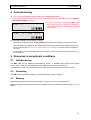
Self Monitoring ..................................................................................................................... 11
5.2
Restarting............................................................................................................................. 11
5.3
Memory ................................................................................................................................ 11
6
Operation
12
6.1
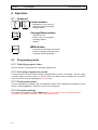
Keyboard .............................................................................................................................. 12
6.2
Programming mode.............................................................................................................. 12
6.2.1
Selecting program items .................................................................................................. 12
6.2.2
Activating programming mode......................................................................................... 12
6.2.3
Setting parameters .......................................................................................................... 12
6.2.4
Accepting settings............................................................................................................ 12
6.3
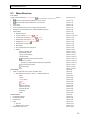
Menu Structure..................................................................................................................... 13
7
Basic Settings 14
7.1
Target maximum demand P1, P2, P3 and P4 ..................................................................... 14
7.2
. Current target maximum demand P1, P2, P3 and P4.................................................... 14
7.3
. Initial value target maximum demand P1, P2, P3 and P4.............................................. 14
7.4
. Upper limit target maximum demand P1, P2, P3 and P4 .............................................. 14
7.5
Peak power P1, P2, P3 and P4 ........................................................................................... 15
7.6
Control delay ........................................................................................................................ 15
7.7
Control Application Point...................................................................................................... 15
7.8
Emergency mode activated at XX% of total sheddable load power .................................... 15
7.9
Other settings....................................................................................................................... 15
7.9.1
Measuring period ............................................................................................................. 15
7.9.2
Counter constant ( P_act1, P_act2) ............................................................................ 16
P_act2) ........................................................... 16
7.9.3
Current transf. ratio Ip/Is: (P_act1, Q,
P_act2) ........................................................ 16
7.9.4
Voltage transf. ratio Vp/Vs: (P_act1, Q,
P_act2)..............................................................................
16
7.9.5
Average over (P_act1, Q,
7.9.6
Counter constant (Q) ....................................................................................................... 16
7.9.7
Cosphi Alarm at cosphi <XX............................................................................................ 16
7.9.8
Bus address..................................................................................................................... 16
7.9.9
Auto summer/winter time changeover ............................................................................. 16
7.9.10
Options............................................................................................................................. 16
7.9.10.1
Number of Profiles Used
16
7.9.10.2
Highest EMD Address
16
7.9.10.3
Type of profile switching
17
7.9.10.4
Active Pulse Monitoring Alarm
19
7.9.10.5
. Group
19
7.9.10.6
Units
19
2