1
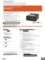
Authorised Distributors:-
ASH & ALAIN INDIA PVT LTD
S-100, F.I.E.E., Okhla Industrial Area, Phase-ii, New Delhi-110020(India)
Tel : 011-43797575 Fax : 011-43797574 E-mail : [email protected]
Up/Down Counting Pulse Indicator
K3HB-C
CSM_K3HB-C_DS_E_7_1
Measure High-speed Up/down Pulses with
this Up/down Pulse Meter.
• Perfect for Measuring Rotary Encoder and ON/OFF Pulse
Signals at High Speed
Cumulative pulse input is 50 kHz, quadrature pulse inputs are 25 kHz,
and up/down pulse inputs are 30 kHz.
Note: No-voltage contacts of up to 30 Hz are supported.
• The count value can be converted to any value.
The length equivalent for any pulse can be set to any desired value.
This is effective for feed amount and position monitor displays.
Refer to Safety Precautions for All Digital Panel
Meters .
Model Number Structure
Model Number Legend
Base Units and Optional Boards can be ordered individually or as sets.
Base Units
Base Units with Optional Boards
K3HB-C
K3HB-C
1
5
1. Input Sensor Code
NB: NPN input/voltage pulse input
5. Supply Voltage
100-240 VAC: 100 to 240 VAC
24 VAC/VDC: 24 VAC/VDC
Optional Board
Sensor Power Supply/Output Boards
K332
Relay/Transistor Output Boards
K343
Event Input Boards
K354
1
2 3 4
5
2. Sensor Power Supply/Output Type Code
None: None
CPA: Relay output (PASS: SPDT) + Sensor power supply
(12 VDC±10%, 80 mA) (See note 1.)
L1A:
Linear current output (0 to 20 or 4 to 20 mA DC) + Sensor power supply
(12 VDC±10%, 80 mA) (See note 2.)
L2A:
Linear voltage output (0 to 5, 1 to 5, or 0 to 10 VDC) + Sensor power
supply
(12 VDC±10%, 80 mA) (See note 2.)
A:
Sensor power supply (12 VDC ±10%, 80 mA)
FLK1A: Communications (RS-232C) + Sensor power supply
(12 VDC±10%, 80 mA) (See note 2.)
FLK3A: Communications (RS-485) + Sensor power supply
(12 VDC±10%, 80 mA) (See note 2.)
3. Relay/Transistor Output Type Code
None: None
C2: Relay contact (HH/H/LL/L: SPST-NO each)
T1: Transistor (NPN open collector: HH/H/PASS/L/LL)
T2: Transistor (PNP open collector: HH/H/PASS/L/LL)
BCD ?:BCD output + transistor output (NPN open collector: HH/H/PASS/L/LL)
DRT: DeviceNet (See note 2.)
* A Special BCD Output Cable (sold separately) is required.
4. Event Input Type Code
None: None
1:
5 inputs (M3 terminal block), NPN open collector
2:
8 inputs (10-pin MIL conn ector), NPN open collector
3:
5 inputs (M3 terminal block), PNP open collector
4:
8 inputs (10-pin MIL connector), PNP open collector
Note: 1. CPA can be combined with relay outputs only.
2. Only one of the following can be used by each Digital Indicator: RS-232C/RS-485 communications, a linear output, or DeviceNet communications.
Accessories (Sold Separately)
Rubber Packing
K32-DICN: Special Cable (for event inputs with 8-pin connector)
K32-BCD: Special BCD Output Cable
Model
K32-P1
Note: Rubber packing is provided with the Controller.
1
K3HB-C
Specifications
■ Ratings
Supply voltage
100 to 240 VAC, 24 VAC/VDC, DeviceNet power supply: 24 VDC
Allowable power supply voltage
range
85% to 110% of the rated power supply voltage, DeviceNet power supply: 11 to 25 VDC
Power consumption
(See note 1.)
100 to 240 VAC: 18 VA max. (max. load)
24 VAC/DC: 11 VA/7 W max. (max. load)
Current consumption
DeviceNet power supply: 50 mA max. (24 VDC)
Input
No-voltage contact, voltage pulse, open collector
External power supply
12 VDC±10% 80 mA
Event inputs
NPN open collector or no-voltage contact signal
ON residual voltage: 2 V max.
ON current at 0 Ω: 4 mA max.
Max. applied voltage: 30 VDC max.
OFF leakage current: 0.1 mA max.
Hold input
Reset input
Bank input
Output ratings Relay output
(depends on
the model)
Transistor output
Linear output
250 VAC, 30 VDC, 5 A (resistive load)
Mechanical life expectancy: 5,000,000 operations, Electrical life expectancy: 100,000 operations
Maximum load voltage: 24 VDC, Maximum load current: 50 mA, Leakage current: 100 µA max.
Linear output 0 to 20 mA DC, 4 to 20 mA DC:
Load: 500 Ω max, Resolution: Approx. 10,000, Output error: ±0.5% FS
Linear output 0 to 5 VDC, 1 to 5 VDC, 0 to 10 VDC:
Load: 5 kΩ max, Resolution: Approx. 10,000, Output error: ±0.5% FS
(1 V or less: ±0.15 V; no output for 0 V or less)
Display method
Negative LCD (backlit LED) display
7-segment digital display (Character height: PV: 14.2 mm (green/red); SV: 4.9 mm (green))
Main functions
Scaling function, measurement operation selection, output hysteresis, output OFF delay, output test, display value
selection, display color selection, key protection, bank selection, display refresh period, maximum/minimum hold, reset
Ambient operating temperature
−10 to 55°C (with no icing or condensation)
Ambient operating humidity
25% to 85%
Storage temperature
−25 to 65°C (with no icing or condensation)
Altitude
2,000 m max.
Accessories
Watertight packing, 2 fixtures, terminal cover, unit stickers, instruction manual. DeviceNet models also include a DeviceNet connector (Hirose HR31-5.08P-5SC(01)) and crimp terminals (Hirose HR31-SC-121) (See note 3.)
Note: 1. DC power supply models require a control power supply capacity of approximately 1 A per Unit when power is turned ON. Particular
attention is required when using two or more DC power supply models. The OMRON S8VS-series DC Power Supply Unit is
recommended.
2. For K3HB-series DeviceNet models, use only the DeviceNet Connector included with the product. The crimp terminals provided are for
Thin Cables.
2
K3HB-C
■ Characteristics
Display range
−19,999 to 99,999
Measurement range
Functions F1, F2: ±2 gigacounts
Functions F3:
0 to 4 gigacounts
Input signals
• Contact input (dry contact input) (30 Hz max. with ON/OFF pulse width of 15 ms min.)
• No contact
Mode Input frequency
ON/OFF
ON voltage OFF voltage
voltage pulse
range
pulse width
F1
F2
F3
• Open collector
Mode
F1
F2
F3
0 to 30 kHz
0 to 25 kHz
0 to 50 kHz
16 μs min.
20 μs min.
9 μs min.
Input frequency
ON/OFF
range
pulse width
0 to 30 kHz
16 μs min.
0 to 25 kHz
20 μs min.
0 to 50 kHz
9 μs min.
4.5 to 30 V
−30 to 2 V
Input
impedance
10 kΩ
Note: The Up/Down Counting Pulse
Meter will malfunction if a pulse
greater than the input frequency
range is input. SYSERR may
appear on the display.
Connectable sensors
ON residual voltage: 3 V max.
OFF leakage current: 1.5 mA max.
Load current:
Must have a switching capacity of 20 mA or higher.
Must be able to properly switch load currents of 5 mA or less.
Max. No. of display digits
5 (−19999 to 99999)
Comparative output response
time
1 ms max.: Transistor output; 10 ms max.: Relay contact output
(time until the comparative output is made when there is a forced sudden change in the input signal from 15%
to 95% or 95% to 15%)
Linear output response time
10 ms max. (time until the final analog output value is reached when there is a forced sudden change in the
input signal from 15% to 95% or 95% to 15%)
Insulation resistance
20 MΩ min. (at 500 VDC)
Dielectric strength
2,300 VAC for 1 min between external terminals and case
Noise immunity
100 to 240 VAC models:
±1,500 V at power supply terminals in normal or common mode
(waveform with 1-ns rising edge and pulse width of 1 μs/100 ns)
24 VAC/VDC models:
±1,500 V at power supply terminals in normal or common mode
(waveform with 1-ns rising edge and pulse width of 1 μs/100 ns)
Vibration resistance
Frequency: 10 to 55 Hz; Acceleration: 50 m/s2, 10 sweeps of 5 min each in X, Y, and Z directions
Shock resistance
150 m/s2 (100 m/s2 for relay outputs) 3 times each in 3 axes, 6 directions
Weight
Approx. 300 g (Base Unit only)
Degree of
protection
Front panel Conforms to NEMA 4X for indoor use (equivalent to IP66)
Rear case
IP20
Terminals
IP00 + finger protection (VDE0106/100)
Memory protection
EEPROM (non-volatile memory)
Number of rewrites: 100,000
Applicable standards
UL61010C-1, CSA C22.2 No. 1010.1 (evaluated by UL)
EN61010-1 (IEC61010-1): Pollution degree 2/Overvoltage category II
EN61326: 1997, A1: 1998, A2: 2001
EMC
EMI: EN61326 industrial applications
Electromagnetic radiation interference
CISPR 11 Group 1, Class A
Terminal interference voltage
CISPR 11 Group 1, Class A
EMS: EN61326 industrial applications
Electrostatic Discharge Immunity
EN61000-4-2: 4 kV (contact), 8 kV (in air)
Radiated Electromagnetic Field Immunity
EN61000-4-3: 10 V/m sine wave amplitude modulation (80 MHz to 1 GHz, 1.4 to 2 GHz)
Electrical Fast Transient/Burst Noise Immunity
EN61000-4-4: 2 kV (power line), 1 kV (I/O signal line)
Surge Immunity
EN61000-4-5: 1 kV with line (power line), 2 kV with ground (power line)
Conducted Disturbance Immunity
EN61000-4-6: 3 V (0.15 to 80 MHz)
Power Frequency Magnetic Immunity
EN61000-4-8: 30 A/m (50 Hz) continuous time
Voltage Dips and Interruptions Immunity
EN61000-4-11: 0.5 cycle, 0°/180°, 100% (rated voltage)
3
K3HB-C
Operation
■ Functions (Operating Modes)
F1 to F3
Function name
Function No.
f1
Individual inputs
Phase differential inputs f2
f3
Pulse counting input
Function
F1
Individual
inputs
Operation
Operation image (application)
Counts input A as incremental pulses and input B as
Counting the number of people entering an area
decremental pulses. The count is incremented on the
rising edge of input A and decremented on the rising
edge of input B. If both inputs rise at the same time, the
Input A
Photoelectric
count is not changed. The count is incremented when
sensor
BCD output
input B is later than input A and decremented when input
B is earlier than input A.
Input B
Input A H
L
Input B H
L
Increment
HOLD input H
L
3
2
Decrement
3
2
2
1
Count
F2
Phase differential inputs
To
Programmable
Controller
1
1
0
This function is normally used when connected to an
Detecting position and speed on a semiconductor wafer conveyor line
incremental rotary encoder. The count is incremented on
Wafer
the falling edge of input B when input A is OFF. The count
is decremented on the rising edge of input B when input
A is OFF.
Input A H
L
(See note 2.)
Input B H
L
E6L
HOLD H
input L
3
2
2
1
Count
F3
Pulse
counting
input
1
1
0
0
Counted on the rising edge of input A
Counting the number of workpieces
Input A H
L
HOLD H
input L
BCD output To
Programmable
Controller
6
5
4
3
2
1
Count
0
Note: 1. Meaning of H and L in Display
Symbol
Input method No-voltage input
H
Short-circuit
L
Open
2. Requires at least half the minimum signal width. If there is less than half, a ±1 count error may occur.
Input Type Setting
NO: Voltage pulse high
NC: Voltage pulse low
No-contact or voltage pulse input 00
01
10
11
Contact
4
K3HB-C
■ What Is Prescaling?
Prescaling converts the count value to any numeric value.
To display @@@@.@ mm in a system that outputs 250 pulses for a 0.5-m feed,
the length per pulse = 500 mm (0.5 m) ÷ 250 = 2.
1. The prescale value for the K3HB-C is set using the mantissa X × exponent Y,
so the prescale value = 2.0000 × 10°,
X = 2.000, and Y = 00.
2. Next, set the decimal point position for one digit to the right of the decimal point:
0.5 m
250 pulses
K3HB-C
Encoder
5
K3HB-C
Common Specifications
■ Event Input Ratings
K3HB-P/-C
HOLD, RESET, BANK1, BANK2, BANK4
Contact
ON: 1 kΩ max., OFF: 100 kΩ min.
No-contact
ON residual voltage:
2 V max.
OFF leakage current:
0.1 mA max.
Load current:
4 mA max.
Maximum applied voltage: 30 VDC max.
■ Output Ratings
Contact Output
Item
Transistor Outputs
Resistive loads
(250 VAC, cosφ=1;
30 VDC, L/R=0 ms)
Rated load
5 A at 250 VAC
5 A at 30 VDC
Rated through
current
5A
Mechanical life
expectancy
5,000,000 operations
Electrical life
expectancy
100,000 operations
Inductive loads
(250 VAC, closed
circuit, cosφ=0.4;
30 VDC, L/R=7 ms)
Maximum load voltage 24 VDC
Maximum load current 50 mA
100 µA max.
Leakage current
1 A at 250 VAC
1 A at 30 VDC
Linear Output
Item
Outputs
0 to 20 mA
Allowable load impedance
500 Ω max.
Resolution
Approx. 10,000
Output error
±0.5% FS
4 to 20 mA
0 to 5 V
Type
RS-232C, RS-485
Communications method Half duplex
Synchronization method Start-stop synchronization (asynchronous)
Baud rate
9600/19200/38400 bps
Transmission code
ASCII
Data length
7 bits or 8 bits
Stop bit length
2 bits or 1 bit
Error detection
Vertical parity and FCS
Parity check
Odd, even
0 to 10 V
±0.5% FS
(±0.15 V for 1 V or less and no output for 0 V)
Serial Communications Output
Item
1 to 5 V
5 kΩ min.
BCD Output I/O Ratings
(Input Signal Logic: Negative)
I/O signal name
Inputs
Item
REQUEST Input signal
CCOMPENSATION
Input current for no-voltage input
RESET
Signal level ON voltage
OFF voltage
Outputs DATA
Maximum load voltage
POLARITY
OVER
Maximum load current
DATA VALID
RUN
Leakage current
OUT1
OUT2
OUT3
OUT4
OUT5
Rating
No-voltage
contact input
10 mA
1.5 V max.
3 V min.
24 VDC
10 mA
100 µA max.
Maximum load voltage
24 VDC
Maximum load current
50 mA
Leakage current
100 µA max.
Refer to the K3HB Communications User's Manual (Cat. No. N129)
for details on serial and DeviceNet communications.
6
K3HB-C
DeviceNet Communications
Communications protocol
Supported
Remote I/O
communications communications
Conforms to DeviceNet
Master-Slave connection (polling, bit-strobe, COS, cyclic)
Conforms to DeviceNet communications standards.
I/O allocations
Allocate any I/O data using the Configurator.
Allocate any data, such as DeviceNet-specific parameters and variable area for Digital Indicators.
Input area: 2 blocks, 60 words max.
Output area: 1 block, 29 words max.
(The first word in the area is always allocated for the Output Execution Enabled Flags.)
Message
communications
Explicit message communications
CompoWay/F communications commands can be executed
(using explicit message communications)
Connection methods
Combination of multi-drop and T-branch connections (for trunk and drop lines)
Baud rate
DeviceNet: 500, 250, or 125 Kbps (automatic follow-up)
Communications media
Special 5-wire cable (2 signal lines, 2 power supply lines, 1 shield line)
Communications distance
Baud rate
Network length
(max.)
Drop line length
(max.)
Total drop line length
(max.)
500 Kbps
100 m max.
(100 m max.)
6 m max.
39 m max.
250 Kbps
100 m max.
(250 m max.)
6 m max.
78 m max.
125 Kbps
100 m max.
(500 m max.)
6 m max.
156 m max.
The values in parentheses are for Thick Cable.
Communications power supply
24-VDC DeviceNet power supply
Allowable voltage fluctuation range
11 to 25-VDC DeviceNet power supply
Current consumption
50 mA max. (24 VDC)
Maximum number of nodes
64 (DeviceNet Configurator is counted as one node when connected.)
Maximum number of slaves
63
Error control checks
CRC errors
DeviceNet power supply
Supplied from DeviceNet communications connector
7
K3HB-C
Connections
■ External Connection Diagrams
Terminal Arrangements
Note: Refer to Internal Block Diagram on page 10 for information on isolation.
A Operating Power Supply
A
B
C
D
E
1
2
3
100 to 240 VAC
24 VAC/VDC
4
5
6
A1
A2
*Check the required power supply type.
B Sensor Power Supply/Output
Sensor power supply + PASS output
C Relays, Transistors, BCD and DeviceNet
B1
Relay Outputs
<C1>
B2
B3
N/C B4
C1
B5 Sensor
12 VDC
80 mA
H
<CPA>
+
0-5/1-5/
0-10 V
N/C
N/C
0-20/
4-20 mA
<L2A>
Transistor Outputs
<T1> <T2>
HH
C1
HH
C1
H
C2
H
C2
NPN
DeviceNet Connector (Included)
<DRT>
PNP
power
B6 supply
Sensor power supply + linear output
12 VDC
80 mA
C2
Relay Outputs
<C2>
1 2 3 4 5
PASS
12 VDC
80 mA
L
C3
COM C3
C4
L
C4
L
C4
C5
LL
C5
LL
C5
C6
B1
PASS C3
COM C6
COM C6
− B2
+
B3
− B4
+
B5 Sensor
power
− B6 supply
<L1A>
Sensor power supply
B1
BCD (NPN Open Collector): <BCD>
1: V− (Power supply cable: Black)
2: CAN L (Communications cable: Blue)
3: Shield
4: CAN H (Communications cable: White)
5: V+ (Power supply cable: Red)
Applicable Connector:
HR31-5.08P-5SC (01)
(HIROSE ELECTRIC CO., LTD.)
* Attach the provided crimp terminals.
Applicable Connector (Sold separately)
HDR-E50MAG1
(HONDA TSUSHIN KOGYO CO., LTD.)
Special Cable (Sold separately)
K32-BCD (OMRON)
(HDR-E50MAG1 with 0.3-m cable)
The BCD COMMON is shared.
The pins indicated in the above diagram
as blank (white) boxes have been removed.
*Only one of the following can be used for each Digital Indicator: communications, BCD, or DeviceNet.
B2
N/C
B3
B4
+
12 VDC
80 mA
Contact Outputs
B5 Sensor
power
−
Transistor Outputs
(NPN Open Collector)
B6 supply
5V
<A>
Sensor power supply + communications
HH
HH
H
H
L
L
B (+)
SD
B1
A (−)
RD
B2
LL
LL
B (+)
SG
B3
PASS
PASS
A (−)
N/C
B4
12 VDC
80 mA
12 VDC
80 mA
+
power
−
RS-485
<FLK3A>
RS-232C
<FLK1A>
B5 Sensor
B6 supply
Safety Standards Conformance
Always use a EN/IEC-compliant power supply with reinforced insulation or double
insulation for the DeviceNet power supply.
The product must be used indoors for the above applicable standards to apply.
8
K3HB-C
E Pulse Inputs
• Up/Down Counting Pulse Meter:
K3HB-C
NPN Input:
K3HB-@NB
Input A
PNP Input:
K3HB-@PB
E1
NPN Input Model
Voltage
Input A
E2
E2, E5
E2
PNP
NPN
E3 COM
E3 COM
E4
E4
510 Ω
10 kΩ
700 Ω
COM
E5
PNP
E6 COM
12 V
510 Ω
E1, E4
Input B
E5
NPN
12 V
700 Ω
Input B
Voltage
• Voltage pulse input section
• NPN input section
E1
E3, E6
E6 COM
E3, E6
Note: A 2-wire DC sensor can also be
connected. Check the ratings
and characteristics tables,
however, for the connection
conditions.
Note: E3 and E6,
Note: E3 and E6, as
as well as B6,
well as B5,
are internally
are internally
connected.
connected.
D Event Inputs
Models with Terminal Blocks
<1> <3>
N/C
N/C
HOLD
RESET
COMPENSATION
COM
• Use terminal pin D6 as the common terminal.
• Use NPN open collector or no-voltage contacts
for event input.
PNP types are also available.
Models with Connectors
<2> <4>
1: N/C
1
3: HOLD
5: COMPENSATION
7: BANK4
9
9: BANK1
2: S-TMR
4: RESET
6: COM
8: BANK2
10 10: COM
2
• Applicable Connector (Sold separately)
XG4M-1030 (OMRON)
• Special Cable (Sold separately)
K32-DICN (OMRON)
(XG4M-1030 with 3-m cable)
12 V
HOLD: D3
RESET: D4
COMPENSATION: D5
4.7 kΩ
3.9 kΩ
D6
Note: The actual terminal label abbreviates "COMPENSATION" to "CMP."
COM
BCD Output Cable
Model
Shape
Pin arrangement
K32-BCD
Connected device end
(PLC, display device, etc.)
K3HB end
300 mm
38 mm
Cover:
HDR-E50LPA5
(manufactured by Honda Tsushin Co., Ltd.)
Connector: HDR-E50MAG1
(manufactured by Honda Tsushin Co., Ltd.)
46.5 mm
D-sub connector (37-pin female)
Cover:
17JE-37H-1A (manufactured by DDK)
Connector: Equivalent to 17JE-13370-02
(manufactured by DDK)
Stud:
17L-002A (manufactured by DDK)
COMMON
1
1
100 2
4
8
1
2
101 4
8
1
2
102
4
8
1
3
10 2
4
8
1
104 2
2
3
4
5
6
7
8
9
10
11
12
13
14
15
16
17
18
19
20
21
22
23
24
25
26
27
28
29
30
31
32
33
34
35
36
37
4 104
8
OVER
DATA VALID
RUN
COMMON
REQUEST
MAX REQ.
MIN REQ.
HOLD
RESET
POLARITY
HH
H
PASS
L
LL
COMMON
Note: The BCD Output Cable has a D-sub plug. Cover: 17JE-37H-1A (manufactured by DDK); Connector: equivalent to 17JE-23370-02 (D1)
(manufactured by DDK)
Special Cable (for Event Inputs with 8-pin Connector)
Model
Appearance
K32-DICN
9
10
1
2
Cable marking
3,000 mm
(3 m)
Wiring
Pin No.
1
2
3
4
5
6
7
8
9
10
Signal name
N/C
S-TMR
HOLD
RESET
N/C
COM
BANK4
BANK2
BANK1
COM
9
K3HB-C
■ Derating Curve for Sensor Power Supply (Reference Values)
Maximum current (mA)
For 12V
140
1
120
100
80
60
40
20
0
−20
−10
0
10
20
30
40
50
60
Ambient temperature (°C)
Note: 1. The above values were obtained under test conditions with the standard mounting. The derating curve will vary with the mounting
conditions, so be sure to adjust accordingly.
2. Internal components may be deteriorated or damaged. Do not use the Digital Indicator outside of the derating range (i.e., do not use it in
the area labeled A, above).
■ Internal Block Diagram
Waveform
shaping circuit
Keys
EEPROM
Indications
• Input circuit
• Output circuit
• Transistor
output circuit
Drive
circuit
Drive
circuit
Event input
Digital input
circuit
Waveform
shaping circuit
Linear output
Linear output
circuit
Drive
circuit
Sensor power
supply
Filter
Pulse input
Pulse input
circuit
BCD
BCD I/O
Microcomputer
VO
Drive
circuit
Transistor
output
Relay output
X
Drive
circuit
DeviceNet
circuit
DeviceNet
Drive
circuit
Communications
driver
Communications
VCOM
VDD
Power supply circuit (isolated)
VO
DC-DC
Converter (isolated)
Power supply
10
K3HB-C
■ BCD Output Timing Chart
A REQUEST signal from a Programmable Controller or other external device is required to read BCD data.
Single Sampling Data Output
Continuous Data Output
20-ms pulse min. (50 ms max.)
REQ.
MAX.MIN.
REQ.
MAX.MIN.
DATA
DATA
All data "High"
All data "High"
Data 1
Data 2
All data "High"
Data
DATA
VALID
DATA
VALID
Approx.
30 ms
40 ms
40 ms
Approx.
30 ms
16 ms
The data is set in approximately 30 ms from the rising edge of the
REQUEST signal and the DATA VALID signal is output.
When reading the data from a Programmable Controller, start
reading the data when the DATA VALID signal turns ON.
The DATA VALID signal will turn OFF 40 ms later, and the data will
turn OFF 16 ms after that.
24 ms
64 ms
40 ms
24 ms
64 ms
Measurement data is output every 64 ms while the REQUEST signal
remains ON.
Note: If HOLD is executed when switching between data 1 and data
2, either data 1 or data 2 is output depending on the timing of
the hold signal. The data will not go LOW.
• The K3HB BCD output model has an open collector output, so wired OR connection is possible
REQ. (1)
K3HB
(1)
Programmable
Controller
REQ. (2)
K3HB
(2)
REQ. (3)
DATA (including POL and
OVER) and DATA VALID can
be used in a wired OR.
RUN, HH, H, PASS, L, and
LL are always output, with or
without a REQUEST signal.
Do not used a wired OR
connect for these signals.
K3HB
(3)
(1)
DATA
(2)
(3)
DATA
VALID
(See note.)
(See note.)
(See note.)
Note: Leave 20 ms min. between DATA VALID turning OFF and the REQUEST signal.
Programmable Controller Connection Example
Digital Indicator
SYSMAC Programmable Controller
DC Input Unit
Connector pin No. (See note.)
1.COMMON
2.1
3.2
IN
2.1
IN
3.2
10°
5.8
Connector pin No. (See note.)
1.COMMON
COM
Internal circuit
4.4
Display Unit Connection Example
Digital Indicator
IN
IN
4.4
5.8
23.DATA VALID
24.RUN
10°
23.DATA VALID
IN
24.RUN
IN
To 101
To 102
240 Ω
240 Ω
240 Ω
25.COMMON
Short26.REQUEST circuit
240 Ω
Internal circuit
+5 V
Transistor Output Unit
OUT
30.RESET
OUT
31.POLARITY
(+/− polarity)
COM
(0 V)
+5 V
240 Ω
240 Ω
30.RESET
240 Ω
240 Ω
24 VDC
31.POLARITY
(+/− polarity)
V
O
D
C
B
A
DP
LE
V
O
D
C
B
A
DP
LE
V
O
D
C
B
A
DP
LE
V
O
26.REQUEST
Internal circuit
25.COMMON
8
8
8
SEC
M7E-01D@N2, 01H@N2
+24 V
0V
<M7E Digital Display Unit>
DC power
supply
Note: The BCD output connector pin number is the D-sub connector pin number when
the BCD Output Cable (sold separately) is connected. This number differs from
the pin number for the Digital Indicator narrow pitch connector (manufactured by
Honda Tsushin Kogyo Co., Ltd.).
Refer to the following User's Manual for application precautions and other information required when using the Digital Indicator:
K3HB-R/P/C Digital Indicator User's Manual (Cat. No. N136)
The manual can be downloaded from the following site in PDF format: OMRON Industrial Web http://www.fa.omron.co.jp
11
K3HB-C
■ Component Names and Functions
Max./Min. status indicator
PV display
Turns ON when the maximum value or minimum
value is displayed in the RUN level.
Displays PVs, maximum values,
minimum values, parameter
names, and error names.
Level/bank display
Position meter
In RUN level, displays the bank if the bank function is
ON. (Turns OFF if the bank function is OFF.)
In other levels, displays the current level.
Displays the position of the PV
with respect to a desired scale.
Comparative output
status indicators
SV display
Display the status of comparative
outputs.
HH
H
P
L
Displays SV and monitor values.
Max
Min
B
L
CMW
Hold
LL
T
HH
H
LL
L
Status indicators
SV display status indicators
MAX/MIN
Function
Display
Hold
Turns ON/OFF when hold input turns
ON/OFF.
Used to switch the
display between the PV,
maximum value, and
minimum value and to
reset the maximum and
minimum values.
MODE
SHIFT
UP
Indicator
CMW
Lit when communications writing is ON
(enabled) and not lit when OFF (prohibited).
MAX/MIN Key
LEVEL
LEVEL Key
Used to switch level.
MODE Key
Used to switch the
parameters displayed.
5
4
3
T
1
2
T
5, 4, 3,
2, 1
SHIFT Key
Used to change
parameter settings.
When changing a set
value, this key is used
to move along the
digits.
Function
Turns ON when parameters for which
teaching can be performed are
displayed.
In RUN level, turn ON when the
comparative set value 1, 2, 3, 4, or 5 is
displayed.
UP Key
When changing a set
value, this key is used
to change the actual
value.
When a measurement
value is displayed, this
key is used to execute
or clear the forced-zero
function or to execute
teaching.
12
K3HB-C
■ Dimensions
101.2
91
Terminal cover (included)
Character Size for Main Display (mm)
PV display
SV display
Panel Cutout Dimensions
120 min.
4.9
14.2
100
3.5
(112)
7.6
75 min.
92+0.8
0
45+0.6
0
12
1.3
95 *
2
96
44.8
48
*DeviceNet models: 97 mm
Terminal: M3, Terminal Cover: Accessory
Wiring Precautions
Mounting Method
• For terminal blocks, use the crimp terminals suitable for M3 screws.
• Tighten the terminal screws to the recommended tightening torque
of approx. 0.5 N·m.
• To prevent inductive noise, separate the wiring for signal lines from
that for power lines.
1. Insert the K3HB into the mounting cutout in the panel.
2. Insert watertight packing around the Unit to make the mounting
watertight.
Watertight
packing
Wiring
• Use the crimp terminals suitable for M3 screws shown below.
5.8 mm max.
5.8 mm max.
Unit Stickers (included)
3. Insert the adapter into the grooves on the left and right sides of
the rear case and push until it reaches the panel and is fixed in
place.
Adaptor
• No unit stickers are attached to the Digital Indicator.
• Select the appropriate units from the unit sticker sheets provided.
LCD Field of Vision
The K3HB is designed to have the best visibility at the angles shown
in the following diagram.
Note: For measurements for commercial purposes, be sure to use
the unit required by any applicable laws or regulations.
10°
30°
Rubber Packing (Sold Separately)
K32-P1
If the rubber packing is lost or damaged, it can
be ordered using the following model number:
K32-P1.
(Depending on the operating environment, deterioration, contraction, or hardening of the rubber
packing may occur and so, in order to ensure
the level of waterproofing specified in NEMA4,
periodic replacement is recommended.)
Note: Rubber packing is provided with the
Controller.
13
K3HB-C
Main Functions
■ Main Functions and Features
Measurement
Function
Outputs
func
The K3HB-R has the following six functions for receiving and
displaying input pulses.
Comparative Output Pattern
out-p
Zone and level comparative output patterns can be selected for
comparative outputs.
F1: Rotation (rpm)/circumferential speed
F2: Absolute ratio
Output OFF Delay
F3: Error ratio
off-d
Delays turning OFF comparatives for a set period. This can be used
to provide sufficient time to read the comparative output ON status
when the comparative result changes at short intervals.
F4: Rotational difference
F5: Flow rate ratio
F6: Passing time
The K3HB-P has the following six functions for receiving and
displaying input pulses.
Shot Output
shot
Turns ON the comparative output for a specific time.
F1: Passing speed
F2: Cycle
Output Logic
F3: Time difference
out-n
Reverses the output logic of comparative results.
F4: Time band
F5: Measuring length
Output Test
F6: Interval
The K3HB-C has the following three functions for receiving and
displaying input pulses.
F1: Individual inputs
Linear Outputs
F2: Phase differential inputs
test
Output operation can be checked without using actual input signals
by using the keys to set a test measurement value.
lset.c, lset.v, lset.h, lset.l
A current or voltage proportional to the change in the measurement
value can be output.
F3: Pulse counting input
Filters
Input Types
in-ta, in-tb, in-ta
Specify the types of sensor connected to input A and input B.
Standby Sequence
stdby
The comparison outputs can be kept OFF until the measurement
value enters the PASS range.
Compensation
Compensation
compn, com-p
The display can be changed to a preset compensation value using
the compensation input.
Key Operations
Teaching
The present measurement value can be used as a scaling value.
Key Protection
Key protection restricts level or parameter changes using the keys to
prevent unintentional key operations and malfunctions.
14
K3HB-C
Display
Other
Display Value Selection
Bank Selection
disp
The display value can be set to the present value, the maximum
value, or the minimum value.
Display Color Selection
color
The present value display color can be set to green or red. The color
of the present value can also be switched according to the
comparative output.
Switch between 8 comparative value banks using the keys on the
front panel or external inputs. A set of set comparative values can be
selected as a group.
Bank Copy
d.ref
When the input changes rapidly, the display refresh period can be
lengthened to control flickering and make the display easier to read.
c opy
Any bank settings can be copied to all banks.
Interruption Memory
Display Refresh Period
bnk - c
memo
The measured value can be recorded when the power supply is
interrupted.
pos - t , pos - h, pos - l
Position Meter
The present measurement value c an be displayed as a position in
relation to the scaling width on a 20-gradation position meter.
Prescale
ps.ax , ps.ay , ps.bx, ps.by
The input signal can be converted and displayed as any value.
Comparative Set Value Display
sv.dsp
Select whether or not to display the comparative value during
operation.
Display auto-return
ret
Automatically returns the display to RUN level when there are no key
operations (e.g., max./min. switching, bank settings using keys).
ALL DIMENSIONS SHOWN ARE IN MILLIMETERS.
To convert millimeters into inches, multiply by 0.03 937. To convert grams into ounces, multiply by 0.03527.
In the interest of product improvement, specif ications are subject to change without notice.
Authorised Distributors:-
ASH & ALAIN INDIA PVT LTD
S-100, F.I.E.E., Okhla Industrial Area, Phase-ii, New Delhi-110020(India)
Tel : 011-43797575 Fax : 011-43797574 E-mail : [email protected]
15