1
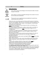
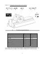
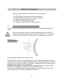
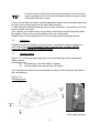
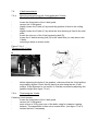
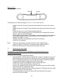
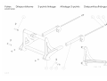
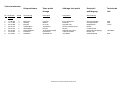
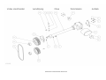
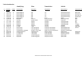
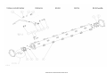
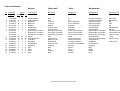
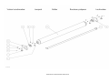
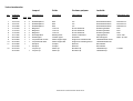
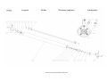
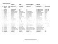
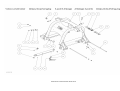
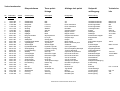
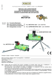
Landmaster
Flailmower
EC Declaration of conformity for machines
Manufacturer:
Adresse :
Code postal :
Town:
Votex B.V.
Groen 2
6666 LP
HETEREN (Netherlands)
declare that the following machines
Votex Landmaster types : 240 - 275 and 310
nr…………….
-
meets the requirements of the directive
Directive 98-37-EC
and the national legislation concerning the execution of this directive
-
meets the requirements of further EEC directives (only fill in if applicable)
and further declare that ;
the following (parts of ) harmonised norms have been applied
-
EN 292-1 1994 / EN 292-2 1996
EN 745 1999
Heteren …………………….
……………………………
(signature)
P.Krieckaert
General Manager.
User's Manual and Parts List
Votex Landmaster
Applicable to the following types:
Landmaster 275
Landmaster 310
delivered after 01 January 2005
VOTEX B.V.
P.O. Box 30
6666 ZG HETEREN
The Netherlands
tel +31(0)26-4790600
fax +31(0)26-4790602
HK 001
Internet : www.votex.nl
E-mail : [email protected]
1
2
Index
1.
Introduction
Page
3
2.
Safety
1.
Safety instructions
2.
Pictograms
3.
Type plate
4
4
9
9
3.
Technical specifications
10
4.
Transport and storage of the mower
11
5.
Putting the mower into operation
1.
Coupling the mower to the tractor
2.
Connecting to tractor hydraulic system
3.
Mounting the universal joint shaft
12
12
12
13
6.
Working with the mower
1.
PTO shaft speed
2.
Adjusting the cutting height
3.
Vibrations in the mower
4.
Uncoupling the mower
13
13
13
14
14
7.
Maintenance
1.
Flails, bolts, flail mountings and wearing plates
2.
Protection
3.
Greasing points
4.
Hydraulic system
5.
Gearbox
6.
V-belt transmission
A) mounting and removing the V-belt guard and V-belts
B) V-belt tensioning
7.
Removing the rotor shaft
8.
Winter storage
15
15
16
16
17
17
18
18
18
19
20
8.
Scrapping the mower
20
9.
Appendix
A. Ordering parts
B. Liability and warranty
C. Notes
D. Conversion table
E. Tightening moments
20
21
21
22
23
23
3
1.
Introduction
You have acquired a Votex Landmaster flail mower. We wish you much success with
this mower and thank you for your confidence in our organization. This manual is
intended for end users and service engineers. Work that may only be done by
service engineers is indicated as such in this book.
This manual contains complete information about safety, operation and maintenance
of the Votex Landmaster flail mowers. We urge you to study this manual carefully,
and then keep it in a safe place for future reference.
Following the rules and recommendations herein described will ensure a properly
operating machine and reduce the risk of accidents!
The Votex Landmaster flail mower is a machine with which plant growth is struck off
by flails fixed to a fast-rotating shaft, then shredded and thrown back to the ground
through a hood.
The machine is intended to be used with tractors with a minimum wheel track of 1.50
m. It enables you to mow and shred grass, weeds and wood wildshoots having a
maximum diameter of 5 cm.
The machines have been designed for mowing on:
- verges
- airfields
- fallow grounds and other stretches of grass
Important!
Any other use is not in accordance with the intended purpose!
The tractor operator must be appropriately qualified and have experience in driving
tractors.
The Votex Landmaster flail mower must not be used for mowing operations in the
vicinity of areas presenting fire and/or explosion hazards.
The flail mower may be used only when the ground roller rests on the ground with its
full width.
Votex B.V. is constantly working on improving its products. They therefore reserves
the right to make any such changes, modifications and/or improvements asthey
consider necessary. However, this does not imply any obligation on its part to make
such changes, modifications and/or improvements to machines previously supplied.
4
2.
2.1.
Safety.
Safety instructions.
This symbol points to acute danger to the life and/or health of human
beings and animals!
This symbol is a warning of possible damage to the mower if the user
does not follow the instructions.
This gives the user suggestions/recommendations for performing
certain tasks safer and easier.
-
-
-
-
-
Study the user's manual thoroughly so that you will be aware of situations
that may cause danger. Make sure you are familiar with the operation of the
tractor, and, in particular, how to stop it in an emergency. Pass all safety
instructions on to other users!
Never let the rotor shaft run when the ground roller is not resting on the
ground with its full length!
The exhaust gases of combustion engines contain carbon monoxide, an
odourless and lethal poison. So, never let the tractor engine run in a
confined space.
In addition to the specific directions contained in this user's manual, also
observe the general regulations in force with regard to safety and the
prevention of accidents!
The pictograms on the machine provide important directions for safe use.
Following these directions will serve your own safety. Replace any
damaged pictograms!
Wear ear protectors at noise levels exceeding 85 dB(A)! Never when using
public roads, however!
When using the machine, wear as much as possible close-fitting clothes!
When using public roads, always observe the road traffic regulations in
force!
Tractors with machines attached to them may be driven only by
appropriately qualified persons with sufficient experience!
Observe the maximum admissible transport dimensions!
If necessary, fit a lighting beam and/or warning signs!
For road transport, put the machine into the appropriate position and lock it
in accordance with directions (see chapter 4)!
When driving on the road with the machine raised, make sure the operating
lever of the lifting device has been secured against unintentional lowering!
If necessary, fit front weights. Always do so in accordance with the
instructions of the tractor manufacturer.
5
Observe the requirements for the maximum admissible axle load/total
weight and the minimum front axle load required (road traffic regulations)!
Do not take any passengers to ride along with you on any part, irrespective
of their age!
Hoses and cables for cylinders and lighting are to be disposed in such a
way that they cannot be damaged under any transport and operating
conditions. Be especially mindful of the fact that wrongly placed hoses may
activate unintended movements or impede necessary functions!
When taking bends, always bear in mind the greater width and length of
your tractor and the greater mass (inertia) of the tractor + mower!
Before driving off and putting the mower into operation, look around the
mower and the tractor, making sure there are no persons within the working
range. Make sure you have an unobstructed view!
It is prohibited to come within the mower's working and danger range.
-
-
-
Keep your distance! Objects (stones and the like) may be hurled
away.
-
Operate the mower only when it is complete and all safeguards are intact.
After bumping into an obstacle, check the mower for any damage.
Immediately repair any damage before resuming working with the machine!
1.
2.
3.
RESIDUAL RISK! The safety guards on the Votex mowers meet the relevant
requirements as set by the European Commission!
Nonetheless, there will be some residual risk to be taken into account.
Objects in the terrain may be picked up and hurled away by the flails!
This may cause serious injury or damage up to a distance of about 50
metres!
In order to minimize this risk, act in accordance with the following safety
recommendations:
Always proceed in accordance with the requirements of the road maintenance
authority and observe the local ordinances and regulations.
If possible, close off roads, cycle paths, footpaths or bridle paths. If this is not
feasible, use a mobile road barrier so that road users will stay at a safe
distance from the machine.
Close off navigable waterways when you have to mowe along them. If this is
not feasible, put up warning signs!
6
-
The speed must be adapted to the terrain and working conditions!
It is dangerous to work with the tractor on slopes! In order to prevent the
tractor from toppling over on slopes, bear in mind the following points.
Do not accelerate abruptly or brake suddenly when driving up or down
a slope!
Slowly let in the tractor-drive clutch and never drive down a slope
without having put the tractor into a gear!
When driving the tractor on slopes and in bends, adjust your speed
accordingly!
Especially on slopes, always be alert to bumps, holes and other
hidden dangers.
Control of a tractor already sliding down can never be regained by
braking!!
Do not mow on slopes having a gradient of more than 5%!
-
Mow only in daylight or good artificial light!
In transport, the PTO shaft must be switched off and the rotor shaft must be
completely at rest!
Stay outside the link-motion range of moving parts!
-
Make sure to avoid toppling over! Work only on sufficiently solid ground!
The following measures must be taken when leaving the tractor and/or
when work is to be done on the machine or universal joint shaft:
Switch off the PTO shaft.
Put the gear lever of the tractor into neutral.
Pull the parking brake of the tractor.
Set the machine entirely down.
Stop the tractor and remove the key from the ignition lock.
Always wait for the rotor shaft to stop completely before approaching
the machine!
Machine is still coming to standstill! Stay away from rotating parts until
they have stopped completely!
-
Make sure the supporting leg is in the lower locked position when coupling
or uncoupling the mower!
Proceed very carefully when coupling and uncoupling the mower. Be
particularly alert to the danger of getting trapped due to accidental operation
of the lifting device. Secure the machine laterally by sufficiently tightening
the stabilizers.
7
Universal joint shaft:
-
-
-
-
Only use the universal joint shaft with freewheel specified by the
manufacturer.
Protecting tubes and guards at the universal joint shaft and the guards on
tractor and machine must be properly fixed and in good condition!
Ensure the specified overlapping of universal joint shaft halves and
protecting tubes, both in the transport and operating position (see user's
manual of universal joint shaft manufacturer).
The universal joint shaft may be coupled and uncoupled only when the
tractor engine has stopped, the ignition key has been removed, and the
machine rests on the ground.
Always ensure that the universal joint shaft is properly mounted and locked!
Secure the guard of the universal joint shaft against turning with the shaft
by fastening both chains to a fixed point on the tractor and machine sides!
Before switching on the PTO shaft, make sure that the speed and direction
of rotation of the PTO shaft correspond to the machine to be driven! The
speed and direction of rotation are indicated on the mower by a pictogram!
The rpm indicated must never be exceeded!
Never switch the PTO shaft on when the engine is not running!
Stay away from a rotating universal joint shaft!
Always switch the PTO shaft off when the angles of the universal joints
threaten to become too great!
Place the uncoupled universal joint shaft into the bracket provided for this
purpose on the three-point linkage!
Fix the protective bush onto the PTO shaft of the tractor as soon as the
universal joint shaft has been uncoupled!
Hydraulic system
A hydraulic system operates under high pressure!
If a leak occurs in it, depressurize the system immediately, collect oil
leaking away, and replace defective parts!
Never put your finger to a hydraulic leak!
Liquid under high pressure easily penetrates skin and clothes, and
causes serious injury. If this should happen, consult a physician
immediately! Oil leaking away is quite harmful to the environment!
Take measures to prevent oil leakage!
8
-
-
-
Regularly check hydraulic hoses, lines and all connections. Replace them
when damaged or aged. New hoses must meet the technical requirements
of the manufacturer!
Shut down the tractor engine, remove the ignition key and depressurize the
hydraulic system before coupling or uncoupling the machine or before doing
any work on the hydraulic system.
Immediately fit dust caps onto disconnected hydraulic hoses.
Lay hoses in such a way as to exclude any soiling and damage!
Maintenance and inspections:
Maintenance and inspections on the underside of the machine must
never be carried out when the machine is held only by the tractor
lifting device. Always take special precautions in order to prevent an
unexpected lowering of the machine. Use a tackle or horse whose
minimum carrying capacity exceeds or is equal to the mass of the
machine (See type plate).
Vibrations in the mower are usually caused by the rotor shaft being
out of balance. These vibrations may cause serious damage to the
mower. When during mowing operations there is a clearly noticeable
increase in vibrations or change in sound produced by the mower,
stop operations immediately, locate the cause and eliminate it before
continuing the work!
-
-
Regularly check flails, flail brackets, bolts and flail mounting plates on the
rotor shaft for wear. For minimum dimensions required, see chapter 7.1!
Make sure the rotor shaft is provided with all flails equally worn off!
Damaged and worn flails, flail brackets and bolts must be replaced
immediately!
Immediately replace rotor shafts that are out of balance or rotor shafts with
worn mounting plates!
Regularly check the metal protecting flaps of the cutting head, and replace
them if showing too much wear.
It is prohibited by law to work with this machine without protecting
flaps/guards or if they are worn!!
Only such persons are allowed to work with and/or on the mower as are
perfectly familiar with it and well aware of possible dangers!
Any and all work to be done on the mower is allowed to be carried out only
with solid and proper tools!
9
2.2.
Pictogramms (see figure 2.1.):
1.
Before putting the machine into operation, read the user's manual and
safety instructions and observe them. (Votex no. 20.10.604)
2.
Direction of rotation and maximum PTO shaft speed 540 rpm
(Votex no. 20.10.600) for rear mounting.
For 1000 rpm (Votex no. 20.10.602)
3.
Do not touch any rotating parts before the machine has come to a standstill
(Votex no. 20.10.605)!
4.
Keep your distance from a rotating rotor shaft. (Votex no. 20.10.606)!
5.
Never come within the link-motion range of moving parts.
(Votex no. 20.10.608)!
6.
Before carrying out any maintenance and repairs, shut down the engine
and remove the ignition key. (Votex no. 20.10.609)!
7.
Lift the machine only at the lifting lug. (Votex no. 20.10.610)
8.
When operating the lifting device, stay outside the lifting range of the threepoint linkage. (Votex no. 20.10.611)!
2.3.
Type plate.
The type plate is provided on the top frame beam, see figure 2.1.
The plate contains the following data:
-
-
Brand name
: VOTEX
Name and address of manufacturer : Votex B.V.
Groen 2
6666 LP HETEREN
The Netherlands
CE marking
: CE
Model
: Landmaster
Type
: 275 or 310
Serial number
:
Year of construction
:
Mass
: 1020 or 1115 kg
Nominal output
: 60 or 70 kW
Max. hydraulic operating pressure : 180 bars
Max. R.P.M. of cutting rotor
: 1830 rpm
10
Figure 2.1 : Pictograms and type plate on the machine
3.
Technical specifications
Type Landmaster
Working width m
Transport width m.
Cutting height setting cm
Mass kg
Mounting category
Mounting
Nominal outpput
Max. range (from centre of tractor) cm
PTO shaft rpm
Max. rotor shaft rpm
Number of flails
Hydraulic connection
275
310
2.73
3.08
2.99
3.31
2.5 - 7.5
2.5 - 7.5
1025
1115
II or III
II or III
Front/pulled
Front/pulled
60 kW
70 kW
183
215
1000
1000
1930 rpm
1930 rpm
30
36
1x DW max. 180 bars
For all types, the sound pressure produced at normal operating speed amounts to 94
dB(A), measured at a height of 1.60 m and at a distance of 1 m from the mower.
11
4.
Transport and storage of the mower.
Transport is to take place with the rotor shaft standing still and the lateral-movement
cylinder in the longest position (mower as narrow as possible).
The mower (when not coupled to a tractor) may be moved only when the following
conditions have been met:
supporting leg in lower position and locked,
side-shift cylinder in the longest position (mower as narrow as possible),
universal joint shaft, if mounted, in the bracket provided for this purpose on
the three-point linkage.
When not coupled to a tractor, the mower can only be moved by lifting it, for which a
sling is laid under the two three-point brackets. Make sure that the sling runs
between the plates of the top-bar mounting so that it cannot move. (see figure 4.1)
Before lifting the machine, always put it into the narrowest position with the side-shift
cylinder. For the lifting operation, use a lifting gear and slings having a lifting capacity
exceeding or equal to the mass of the mower. For this, see the type plate on the
machine.
Place the mower on horizontal solid ground with a minimum
strength of 400 kPa (ca. 4 kg / cm²).
Figure 4.1
Lifting lugs
When the mower is to be stored, it is advisable slide the side-shift cylinder fully
inwards in view of the risk of damage or corrosion.
If this is not possible, the cylinder rod must be lubricated with vaseline in view of the
risk of corrosion.
For winter storage, we refer to chapter 7.9.
12
5.
Putting the mower into operation.
Prior to coupling the mower, check whether the data on direction and speed of
rotation as stated on the machine (see figure 5.1.) correspond to the direction and
speed of rotation of the tractor PTO shaft.
Figure 5.1
Speed and direction of
rotation of PTO shaft
5.1.
Coupling the mower to the tractor.
The Votex Landmaster flail mower can be mounted to tractors using a cat. II or III
linkage mechanism.
To couple the mower to the tractor, proceed as follows:
-
place the tractor in front of the mower so that the drawbars can be coupled
to the machine,
pull the parking brake of the tractor and put the gear lever(s) into neutral,
When operating the linkage mechanism, stay outside the lifting range
of the three-point linkage.
-
5.2.
fix both drawbars to the mower using the lifting-arm pins and fit the spring
clips,
turn off the tractor engine and remove the ignition key,
mount the universal joint shaft and both chains of the guard,
mount the top bar and top-bar pin(s) and secure them,
adjust the machine horizontally by turning the top bar,
reduce the lateral play of the mower in the three-point linkage to a
minimum.
Connecting the tractor hydraulic system.
Before connecting the hydraulic hoses, turn off the tractor engine, remove ignition
key, and depressurize the tractor hydraulic system!
The hydraulic hoses of the Votex Landmaster are provided with 1/2" BSP connectors.
The female connectors should be on the tractor. A double-acting control valve is
required for the lateral movement of the cutting head.
Any costs to be incurred for adapting the tractor hydraulic system will be for account
of the user.
13
After disconnecting the hydraulic hoses, the dust caps included in the delivery must
be pushed on the quick connectors so as to prevent sand and dirt from getting into
the tractor hydraulic system.
Damage to the tractor hydraulic system cannot be charged to the manufacturer.
Normal use of the Votex Landmaster flail mower will not lead to the tractor hydraulic
system being loaded heavily.
5.3.
Mounting the universal joint shaft.
Before mounting the universal joint shaft, turn off tractor engine and remove ignition
key!
Use the universal joint shaft of the Votex Landmaster flail mower in accordance with
the manufacturer's instructions.
The freewheel is incorporated in the gearbox. Make sure that universal joint shaft
connections are well secured to tractor and mower. Only use a complete universal
joint shaft guard provided with securing chains which must be firmly fastened to the
tractor and mower so that it cannot turn with the shaft.
Take into account all angles that the universal joint shaft can conceivably form.
In addition, both the tractor and the machine must be provided at the shaft ends with
solid guards overlapping the universal shaft guard by at least 50 mm.
The universal joint shaft must not be too long. To determine the proper
shaft length, the upward movements and swinging of the machine and the
turning inwards and outwards of the top bar must be taken into account. For
mounting, shortening and maintenance, see the user's manual of the
universal joint shaft!
6.
Working with the mower.
After the initial 8 running hours, retighten all bolt connections (boltconnection tightening moment for flail mounting: 80 Nm)!
6.1
PTO shaft speed.
The PTO shaft speed indicated on the machine must never be exceeded!
The PTO shaft speed indicated on the machine corresponds to a rotor-shaft speed of
approx. 1930 rpm, which ensures the best cutting action.
6.2.
Adjusting the cutting height.
The cutting height of the Votex Landmaster flail mower can be adjusted by altering
the ground-roller supports in relation to the cutting head.
14
6.3
Vibrations in the machine.
When during mowing operations there is a clearly noticeable increase in vibrations or
change in sound produced by the mower, then stop operations immediately, locate
the cause and eliminate it (see 7.1) before continuing the work!
6.4
Uncoupling the mower.
Place the mower on horizontal solid ground with a minimum strength
of 400 kPa (ca. 4 kg/cm²)
Be alert to residual pressure when uncoupling hydraulic hoses!
-
-
pull the parking brake of the tractor and put the gear lever(s) into neutral,
put the side-shift cylinder into the shortest position (For storage including
winter storage, preferably in the shortest position),
put the supporting leg into the lower position and lock it in place,
lower the machine to the ground,
shut down the tractor engine and remove the ignition key,
then depressurize the hydraulic system of the machine by moving the
levers, provided on the tractor for operating the lift cylinder and sliding
cylinder, a few times back and forth,
disconnect the hydraulic hoses and fit the dust caps,
remove the universal joint shaft on the tractor side and place it into the
bracket provided for this purpose,
remove top-bar and lifting-arm pins,
remove the lighting plug if mounted.
15
7.
Machine maintenance.
Inspection and maintenance may be carried out only when:
- The PTO shaft of the tractor has been switched off
- The lifting device of the tractor is in its lower position
- The tractor engine has been shut down
- The ignition key has been removed
- The hydraulic system has been depressurized
7.1.
Flails, bolts, flail mountings and wearing plates.
Flails, bolts and mounting plates on the rotor shaft must be checked regulartly for
wear.
Never work with flails, bolts and mounting plates that do not meet the
minimum-dimension requirements! For this, see figure 7.1.1. Immediately
replace any parts that do not meet the minimum dimensions required!
See figure 7.1.1
Minimum dimensions
of flail mountings
Flail mounting nut tightening moment: 80 Nm
Worn flails result in poor cutting quality that looks bad. When this happens, replace
all flails and, if necessary, all bolts. Replacing only the flails that are most worn would
render the rotor shaft out of balance, resulting in vibrations which may cause serious
damage to your mower in a very short time.
Vibrations may point to one or more (heavily) damaged flails. Also, objects wound
around the rotor shaft (e.g. barbed wire) may cause vibrations.
In the event of vibrations and/or changes in the mower sound, switch off the PTO
shaft immediately, then locate and eliminate the cause!
16
Excessive wear of flails, bolts and mounting plates on the rotor shaft
may be caused by too low a rotor shaft speed and/or frequent contact
of the flails with soil or water.
If one or more flails have been (heavily) damaged, replace them with specimens that
are worn to the same degree as the other flails mounted.
If, after taking the above measures, there are still vibrations in the machine, this may
point to a bent rotor shaft.
If so, contact your dealer. Never try to repair a rotor shaft yourself! Regularly check
the degree of wear of the wearing plates under the cutting head.
Replace them if there appears to be a risk of wearing the underlying material.
7.2.
Protection.
Regularly check the condition of the protection. Immediately replace damaged or
worn rubber flaps! It is prohibited by law to operate this machine without
protecting flaps/guards or if they are worn!!
7.3.
Greasing points.
Figure 7.3.1. shows the greasing points to be lubricated daily with multipurpose
lithium grease.
Greasing points:
A
End bearing of the rotor shaft (2 nipples)
B
Ball bearings of the ground roller (2 nipples)
The universal joint shaft must be lubricated according to the lubrication schedule of
the manufacturer.
Figure 7.3.1
Greasing points.
Rotor shaft greasing
17
point on driving side
7.4.
Hydraulic system.
The hydraulic oil in hoses and cylinders is replaced automatically when replacing the
hydraulic oil of the tractor. It is therefore important to follow the pertinent instructions
of the tractor manufacturer.
7.5.
Gearbox.
The oil content required for the gearbox is 3.3 l of Gear Oil SAE 90 API GL4. The
gearbox oil is to be changed for the first time after 20 running hours and
subsequently once in a season. In addition, it is necessary to check regularly via the
level plug on the gearbox (inside the PTO shaft guard) for any leakages.
The necessary freewheel is incorporated in the gearbox.
Changing the oil: (see figure 7.5.1)
Remove the PTO shaft to gain access to the level plug on the gearbox,
clean the gearbox around the drain, filler and level plugs,
loosen the drain plug on the underside of the gearbox and collect the oil
place the plug back,
remove the level plug (depending on front or rear mounting located inside
the PTO shaft guard)
remove the filler plug on top of the box,
fill the box through this hole with 3.3 l of oil,
the oil should then reach the level of the level plug,
place the two plugs back.
Figure 7.5.1
Checking the oil level
Drain plug
Filler plug
Level plug
18
7.6.
V-belt transmission.
7.6.a
Mounting and removing the V-belt guard and V-belts
(See figures 7.6.a.1 ; 7.6.b.1 and 7.6.b.2)
-
loosen the fixing bolts of the V-belt guard,
remove the V-belt guard,
slightly loosen the 3 bolts (A) by which the gearbox is fixed to the cutting
head,
slightly loosen the 2 bolts (C) by which the drive housing is fixed to the side
plate,
loosen the lock nut of the V-belt tensioning bolt (D),
loosen the V-belt tensioning bolt (D) to the extent that you can remove the
V-belts,
mounting is done in reverse order.
-
Figure 7.6.a.1
Tensioning the V-belts
A
-
before tightening the bolts of the gearbox, make sure that the V-belt pulleys
are properly aligned. Check this by placing a ruler along the two V-belt
pulleys. If the alignment is not correct, it must be corrected by adjusting the
gearbox height.(see figure 7.6.a.1)
7.6.b.
Tensioning the V-belts.
Checking V-belt tension:
loosen the fixing bolts of the V-belt guard,
remove the V-belt guard,
exert a force of 10 kg upon one of the belts, using for instance a spring
balance. The depression is then not to exceed 9mm. (see figure 7.6.b.1),
tension the belt, if necessary
19
Figuur 7.6.b.1
Checking V-belt tension
Tensioning the V-belts (see figures 7.6.a.1 ; 7.6.b.1 and 7.6.b.2)
-
-
slightly loosen the 3 bolts (A) by which the gearbox is fixed to the cutting
head,
slightly loosen the 2 bolts (D) by which the drive housing is fixed to the side
plate,
loosen the lock nut of the V-belt tensioning bolt (D),
turn the V-belt tensioning bolt (D) until the belts have reached the correct
tension, and secure the bolt again,
before tightening the bolts of the gearbox, make sure that the V-belt pulleys
are properly aligned. Check this by placing a ruler along the two V-belt
pulleys, (see figure 7.6.b.2)
retighten the bolts of the gearbox and the drive housing,
mount the V-belt guard.
Note:
First-time retensioning must be carried out after operating the
mower for about 15 minutes. The tension and condition of the Vbelts are subsequently to be checked at regular intervals.
7.7
Removing the rotor shaft
The operations described below are allowed to be performed only by the
manufacturer or dealer!
To remove the rotor shaft, proceed as follows:
using a tackle or fork-lift truck, bring the flail mower in a position lying on its
side so that the ground roller lies on the ground. The best way to manage
this is by fastening a sling to each top-bar pin. Make sure that the sling on
the ground-roller side is longer than on the other side.
support the machine with blocks so that it cannot fall back
remove the V-belts as described in chapter 7.6.a
remove the taperlock pulley on the rotor shaft by turning one of the sockethead screws in the appropriate hole
fasten a tackle having a minimum lifting capacity of 300 kg to the rotor shaft
to be able to lift it out of the frame.
on both side plates, remove the three M12 bolts by which the ring is
secured on the rotor shaft
20
-
-
on the driving side, remove the guide block at the bottom of the side plate
and the vertical lip screwed to it
remove the bolts of both bearing blocks holding the rotor shaft in the cutting
cap
lift the rotor shaft out of the machine
Mounting the rotor shaft is done in reverse order
7.8.
Winter storage.
-
In the event the machine is put out of service for an extended period of time, it will be
necessary to perform an intensive cleaning. Thereupon, lubricate all greasing points
(see chapter 7.3) and change the gearbox oil (see chapter 7.5). After this, have the
machine run for a few minutes. Make sure that the cylinder is in its slid-in position.
8.
Scrapping the mower.
When the machine is to be scrapped, you must take the following measures:
place a drain pan under the gearbox and drain the oil,
remove all hydraulic components and collect the oil.
Slide the cylinder a few times in and out and collect the residual oil,
remove grease from:
bearing housings including bearings,
ground-roller bearings
Remove all rubber and synthetic parts and dispose of them in accordance with the
regulations in force. Dispose of the grease and oil in accordance with the regulations
in force. Dispose of the remaining parts as scrap iron.
Appendix.
A.
B.
C.
D.
E.
Ordering parts.
Liability and warranty.
Notes.
Conversion table.
Tightening moments.
21
A.
Ordering parts.
Your order for parts should contain the following details (see type plate):
Model
Type
Serial number
Part number, part name and quantity
For any part whose number cannot be determined with certainty, you may send the
original in order to avoid delivery of a wrong part. The parts of the figures in this
manual may show differences with the original because due to design adaptations or
improvements a particular part may have been changed prior to the release of a new
edition of this book. It is therefore advisable not to rely on the illustrations. Use
original Votex parts only so that you will be assured of excellent quality and a good
fit.
B.
Liability and warranty.
Votex B.V. guarantees the proper operation of your machine for a period of 12
months after delivery, provided the instructions contained in this manual are followed
as described.
The machine shall be used only by persons who have thoroughly studied
this manual beforehand, and are well aware of the dangers that may result
from not properly following pertinent instructions. This also applies to the
persons responsible for adjusting and servicing the machine.
The machine shall be used only for the specified purposes.
Always duly observe the safety instructions.
Replacement parts will be compensated within the period of
guarantee only if they have been ordered from Votex B.V.
Use only original Votex parts/components and the specified lubricants.
Always duly observe the local safety regulations as in force with regard to
the prevention of accidents, transport safety and traffic regulations.
Important!
This manual applies to the original Votex technical design and
construction of your machine. Votex B.V. can therefore not be held
responsible and disclaims any liability for any damage resulting from
any technical alteration or change independently made to the machine
and from the use of any parts other than from Votex. This provision
also applies to the use of any other lubricants, improper or insufficient
maintenance and any repairs carried out improperly, without prior
consultation with Votex B.V.
-
Please note that:
In case this manual is not correctly complied with, Votex B.V. cannot
be held liable for any warranty claims within the period of guarantee.
The terms of delivery and payment used by Votex B.V. are the terms
and conditions of the Metaalunie. These have been lodged with the
Registry of the Court of Rotterdam.
22
-
C.
They include the Algemene Handelsvoorwaarden
Landbouwwerktuigen en -uitrustingen (AHL) (general terms of
business for agricultural machinery and equipment).
If the guarantee card and user declaration have not been correctly
and completely filled in and returned to Votex B.V. within 14 days after
delivery, warranty requests, if any, will not be considered.
Notes.
All rights reserved.
No part of this book may be reproduced and/or made public by means of reprint,
photocopy, microfilm or in any other form whatsoever, without the express prior
permission in writing from Votex B.V. This also applies to the accompanying
drawings and diagrams.
Votex B.V. reserves the right to adapt parts for improvement at any time, without
prior notice to the buyer.
Likewise, the contents of this manual may be changed accordingly without prior
notice.
For information about adjustments, maintenance or repairs not covered by this
manual, we recommend that you contact the technical department of your supplier.
23
D.
Conversion table.
Length
1 m = 100 cm = 1000 mm
Volume
1 m3 = 1000 dm3 = 1000 l
Force and weight
1 N = 0.102 kg (f) = 0.102 kp
Pressure and stress
1 bar = 0.987 atm = 100 kPa = 100 kN/m
Tightening moment
1 Nm = 0.102 kg (f) m
Power
1 kW = 1000 W = 1.36 pk = 1.36 cv =
1.34 hp
Number of revolutions
1 omw./min = 1 tpm = 1 U/min = 1 tr/mn = 1 min-1
Speed
1 km/h = 0.278 m/s
E.
Tightening moments.
All bolt connections must be tightened according to the table below, unless otherwise
stated in the manual or parts list.
Thread
M 8
M 10
M 12
M 14
M 16
M 18
M 20
Tightening moment
(Nm)
24
49
84
133
205
290
410
24
25
26
Votex Landmaster
No Onderdeel
nummer
1
2
3
4
5
6
7
8
11.05.020
12.11.020
20.01.008
20.01.132
20.01.133
45.07.836
45.07.840
45.07.843
Aantal
4
4
3
1
2
1
2
2
Driepuntsframe
Three points
linkage
Attelage trois points
Dreipunkt
aufhängung
Omschrijving
Description
Designation
Beschreibung
Borgmoer
Sluitring
Borgclip
Topstangpen
Werktuigpen
Driepuntsframe
Framebuis
Draadeind
Lock nut
Washer
Linch pin
Top link pin
Link pin
Three points linkage
Frame tube
Threaded rod
Écrou autofreiné
Rondelle
Goupille clips
Broche troisieme point
Broche
Attelage trois points
Tube de Châssis
Tige filetée
Sicherungsmutter
Unterlegscheibe
Klappstecker
Bolzen
Lenker bolzen
Dreipunkt Aufhängung
Ramen rohr
Gewindestange
Onderdelen Landmaster2006 hk001.XLS
Technische
info
M20
M20
11mm
LM+RM07
M20
Onderdelen Landmaster2006 hk001.XLS
Votex Landmaster
nr. onderdeel
nummer
1
2
3
4
5
6
7
8
9
10
11
12
13
14
15
16
17
18
19
20
10.02.087
10.02.153
10.02.165
10.02.207
11.02.012
11.05.016
12.01.012
12.11.008
12.11.012
12.15.516
15.09.060
19.06.210
27.10.149
27.10.181
28.01.311
36.06.008
36.06.216
36.06.217
45.09.633
45.09.650
aantal
8
4
1
2
2
2
4
8
1
2
2
4
1
1
1
1
1
1
1
1
Aandrijving
Drive
Transmission
Antrieb
Omschrijving
Discription
Designation
Beschreibung
technische info
Zeskanttapbout
Zeskanttapbout
Zeskanttapbout
Zeskanttapbout
Zeskantmoer
Borgmoer
Veerring
Sluitring
Sluitring
Sluitring
Inlegspie
V-snaar
Afscherming
Afscherming
Tandwielkast+ aandrijfas
Taperlock klembus
V-snaarschijf
V-snaarschijf
Spanplaat
Spanplaat
Bolt
Bolt
Bolt
Bolt
Nut
Lock nut
Spring washer
Washer
Washer
Washer
Sunk key
V-belt
PTO shaft guard
PTO shaft guard
Gearbox+ drive shaft
Taperlock bush
V-belt pulley
V-belt pulley
Tensionning plate
Tensionning plate
Vis
Vis
Vis
Vis
Écrou
Écrou autofreiné
Rondelle grower
Rondelle
Rondelle
Rondelle
Clavette
Courroie
Protection transmission
Protection transmission
Boitier à renvoie d'angle+axe
Moyeu conique
Poulie à gorges
Poulie à gorges
Plaque de tension
Plaque de tension
Sechskantschraube
Sechskantschraube
Sechskantschraube
Sechskantschraube
Mutter
Sicherungsmutter
Federring
Unterlegscheibe
Unterlegscheibe
Unterlegscheibe
Paßfeder
Keilrieme
GelenkwelleSchutz
GelenkwelleSchutz
Getriebe+ antriebswelle
Spanbüchse
Keilriemenscheibe
Keilriemenscheibe
Spannplatte
Spannplatte
M8x16-8.8
M12x35-8.8
M12x100-8.8
M16X45-8.8
M12
M16
M12
M8
M12
17x40x6
14x9x60
XPB-1800
P82.25
Onderdelen Landmaster2006 hk001.XLS
3020-45 TL
300SPB4
250SPB4
Onderdelen Landmaster2006 hk001.XLS
Votex Landmaster
nr. onderdeel
nummer
1
2
3
4
5
6
7
8
9
10
11
12
13
14
15
16
17
18
19
20
21
22
23
24
26
27
28.11.301
28.11.302
18.11.010
18.11.011
18.11.013
12.30.040
28.09.006
28.11.310
12.31.080
17.01.014
17.01.063
12.30.048
26.10.536
77.26.192
10.02.151
28.11.305
28.11.306
10.28.152
12.31.100
18.01.011
28.11.308
28.11.303
28.11.309
28.11.304
28.11.307
28.11.300
aantal
1
1
2
1
1
2
1
1
2
2
1
1
1
4
8
6
3
4
2
1
1
1
1
1
1
1
Tandwielkast
Gearbox
Boîtier à renvoie d'angle
Getriebe
Omschrijving
Discription
Designation
Beschreibung
Tandwielkasthuis
Tandwielkastdeksel
Kegellager
Kegellager
Kegellager
Zekeringsring
Shim
Afstandsring
Zekeringsring
Keerring
Keerring
Zekeringsring
Ontluchtingsnippel m.klep
Plug
Zeskanttapbout
Veer
Inlegspie
Cilinderkopschroef
Zekeringsring
Kogellager
Aandrijfas
Kegelwiel
As
Pionwiel
Aandrijfhuis
Aandrijfas
Gearbox case
Boitier
Gearbox cover
Couvercle
Tapered rolling bearing Roulement à rouleau conique
Tapered rolling bearing Roulement à rouleau conique
Tapered rolling bearing Roulement à rouleau conique
Circlip
Circlip
Shim
Rondelle de réglage
Distance ring
Rondelle d'entretoise
Circlip
Circlip
Seal ring
Joint d'étanchéité
Seal ring
Joint d'étanchéité
Circlip
Circlip
Air release nipple w.valveReniflard d'air avec valve
Plug
Bouchon filetée
Bolt
Vis
Spring
Ressort
Sunk key
Clavette
Cilinderheadscrew
Vis à tête cilindrique
Circlip
Circlip
Ball bearing
Roulement à billes
Drive shaft
Arbre d'entraînement
Crownwheel
Pignon
Shaft
Arbre
Pignon wheel
Pignon
Drive house
Cage d'entraînement
Drive shaft
Arbre d'entraînement
Onderdelen Landmaster2006 hk001.XLS
Getriebegehäuse
Getriebedeckel
Kegellager
Kegellager
Kegellager
Sicherungsringe
Paßscheibe
Distanzring
Sicherungsringe
Simmerring
Simmerring
Sicherungsringe
Entlüfter m.klappe
Verschlüßschraube
Sechskantschraube
Feder
Paßfeder
Zylinderkopfschraube
Sicherungsringe
Kugellager
Antriebswelle
Kegelzahnrad
Welle
Kegelzahnrad
Antriebsgehäuse
Antriebswelle
technische info
30208-J2
32208-J2
30308-J2
40x1.75
40x50x0.5mm
80x2.5
40x80x10
45x100x10
48
R3/8
3/8"
M12x25-8.8
M12x30
100x3
6309
25T
15T
LM
Onderdelen Landmaster2006 hk001.XLS
Votex Landmaster
no. onderdeel
nummer
1
2
3
4
5
6
7
8
9
10
11
12
13
14
15
16
17
18
19
20
10.02.092
10.02.120
10.02.153
10.04.137
11.05.008
11.05.010
11.05.012
12.11.008
12.11.010
20.01.004
43.05.120
45.01.821
45.01.841
45.01.860
45.05.232
45.10.607
45.10.616
45.11.526
45.25.016
45.25.020
45.25.040
45.05.936
45.25.023
45.25.043
45.25.100
45.25.026
45.25.046
45.25.103
240
43
2
3
2
43
4
3
15
2
1
1
Aantal
275 310
49
2
3
2
49
4
3
17
2
1
1
1
55
2
3
2
55
4
3
19
2
1
1
1
1
14
1
1
1
2
16
1
1
1
2
1
18
1
1
1
2
1
2
1
1
1
1
1
1
Maaigedeelte
Cutting head
Carter de broyage
Mähergehäuse
Omschrijving
Discription
Designation
Beschreibung
technische info
Zeskanttapbout
Zeskanttapbout
Zeskanttapbout
Zeskantbout
Borgmoer
Borgmoer
Borgmoer
Sluitring
Sluitring
Borgveer
Vergrendelpen
Maaigedeelte
Maaigedeelte
Maaigedeelte
Rubberflap
V-snaar afschermkap
Plaatje
Steunpoot
Slijtplaat
Klemstrip
Klemstrip
Klemstrip
Klemstrip
Klemstrip
Klemstrip
Rubberflap
Rubberflap
Rubberflap
Bolt
Bolt
Bolt
Bolt
Lock nut
Lock nut
Lock nut
Washer
Washer
Gripclip
Locking pin
Cutting head
Cutting head
Cutting head
Rubbersheet
V-belt guard
Plate
Parking leg
Wearing plate
Clamping strip
Clamping strip
Clamping strip
Clamping strip
Clamping strip
Clamping strip
Rubber sheet
Rubber sheet
Rubber sheet
Vis
Vis
Vis
Vis
Écrou autofreiné
Écrou autofreiné
Écrou autofreiné
Rondelle
Rondelle
Goupille beta
Axe de veroullage
Carter de broyage
Carter de broyage
Carter de broyage
Protection en caoutchouc
Protection de courroie
Plaque
Béquille
Tôle d'usure
Barre de serrage
Barre de serrage
Barre de serrage
Barre de serrage
Barre de serrage
Barre de serrage
Protection en caoutchouc
Protection en caoutchouc
Protection en caoutchouc
Sechskantschraube
Sechskantschraube
Sechskantschraube
Sechskantschraube
Sicherungsmutter
Sicherungsmutter
Sicherungsmutter
Unterlegscheibe
Unterlegscheibe
Federstecker
Bolzen
Mähergehäuse
Mähergehäuse
Mähergehäuse
Gummistreifen
KeilriemenSchutzblech
Zunge
Stütze
Sohle
Klemmleiste
Klemmleiste
Klemmleiste
Klemmleiste
Klemmleiste
Klemmleiste
Gummistreifen
Gummistreifen
Gummistreifen
M8x30-8.8
M10x25-8.8
M12x35-8.8
M10x130-8.8
M8
M10
M12
M8
M10
4mm
Onderdelen Landmaster2006 hk001.XLS
Landmaster 275
Landmaster 310
Landmaster 240
174x174x8mm
Landmaster
Landmaster
B=878mm
Onderdelen Landmaster2006 hk001.XLS
Votex Landmaster
Rotoras
no. onderdeel
nummer
1
2
3
4
5
6
7
8
9
10
11
12
13
14
15
16
17
10.02.065
10.02.207
11.05.006
11.05.016
12.11.006
20.03.003
20.03.004
45.02.472
45.02.492
45.02.562
45.03.260
45.03.263
45.09.640
18.06.021
45.09.643
80.26.947
80.26.950
80.26.951
80.26.954
45.10.613
Aantal
Omschrijving
240 275 310
1
8
1
8
2
1
1
1
8
1
8
2
1
1
1
1
8
1
8
2
1
1
1
1
26
26
2
2
1
1
2
2
1
2
30
30
2
2
1
1
2
2
1
2
36
36
2
2
1
1
2
2
1
2
Zeskanttapbout
Zeskanttapbout
Borgmoer
Borgmoer
Sluitring
Smeernippel
Smeernippel
Rotoras kpl. m. klepels
Rotoras kpl. m. klepels
Rotoras kpl. m. klepels
Klepel
Klepelbout+moer
Lagerhuis
Kogellager
Smeerleiding
Koppeling
Ring
Moer
Steun
Ring
Rotor shaft
Rotor
Messerwelle
Discription
Designation
Beschreibung
technische info
Bolt
Bolt
Lock nut
Lock nut
Washer
Grease nipple
Grease nipple
Rotorshaft cpl.w.flails
Rotorshaft cpl.w.flails
Rotorshaft cpl.w.flails
Flail
Flail bolt+nut
Bearing house
Ball bearing
Lubricate tube
Coupling
Ring
Nut
Support
Ring
Vis
Vis
Écrou autofreiné
Écrou autofreiné
Rondelle
Graisseur
Graisseur
Rotor cpl.avec fléaux
Rotor cpl.avec fléaux
Rotor cpl.avec fléaux
Fléau
Vis de fléau+écrou
Palier à roulement
Roulement à billes
Conduite de lubrification
Raccord
Bague
Écrou
Support
Anneau
Sechskantschraube
Sechskantschraube
Sicherungsmutter
Sicherungsmutter
Unterlegscheibe
Schmiernippel
Schmiernippel
Messerwelle mit schlegel
Messerwelle mit schlegel
Messerwelle mit schlegel
Schlegelmesser
Schlegelschraube+Mutter
Lagergehäuse
Kugellager
Schmierleitung
Kupplung
Ring
Mutter
Stutze
Ring
M6x25-8.8
M16X45-8.8
M6
M16
M6
M8x1.25-180°
M8-45°
Landmaster 275
Landmaster 310
LM 240 1.3 kg
1.3 kg
M16x100-10.9
Onderdelen Landmaster2006 hk001.XLS
YAR-212-2F
Onderdelen Landmaster2006 hk001.XLS
Votex Landmaster
no.
1
2
3
4
5
6
7
8
9
10
11
12
onderdeel
nummer
10.02.153
10.02.181
10.02.206
11.05.012
11.05.014
11.05.016
18.31.032
20.03.003
45.25.000
45.25.003
45.25.006
45.25.030
45.25.010
45.25.033
Looprol
Roller
Rouleau palpeur
Laufrolle
Omschrijving
Discription
Designation
Beschreibung
technische info
Zeskanttapbout
Zeskanttapbout
Zeskanttapbout
Borgmoer
Borgmoer
Borgmoer
Flenslagerblok
Smeernippel
Looprolhouder rechts
Looprolhouder links
Schraper
Schraper
Looprol cpl.
Looprol cpl.
Bolt
Bolt
Bolt
Lock nut
Lock nut
Lock nut
Bearing block
Grease nipple
Roller support right
Roller support left
Scraper
Scraper
Roller cpl.
Roller cpl.
Vis
Vis
Vis
Écrou autofreiné
Écrou autofreiné
Écrou autofreiné
Palier à roulement
Graisseur
Support de rouleau droite
Support de rouleau gauche
Racloire
Racloire
Rouleau cpl.
Rouleau cpl.
Sechskantschraube
Sechskantschraube
Sechskantschraube
Sicherungsmutter
Sicherungsmutter
Sicherungsmutter
Lagergehäuse
Schmiernippel
Laufwalzestutz rechts
Laufwalzestutz links
Schürfleiste
Schürfleiste
Laufwalze kpl.
Laufwalze kpl.
M12x35-8.8
M14x40-8.8
M16x40-8.8
M12
M14
M16
UCFL 208
M8x1.25-180°
275 310
4
4
4
4
4
4
2
2
1
1
1
4
4
4
4
4
4
2
2
1
1
1
1
1
Onderdelen Landmaster2006 hk001.XLS
L=3050
Onderdelen Landmaster2006 hk001.XLS
Votex Landmaster
Looprol
no. onderdeel
nummer
1
2
3
4
5
6
7
8
9
10
11
12
13
14
15
16
17
18
19
20
21
22
23
24
25
10.02.207
10.04.158
10.29.123
10.28.095
11.05.010
11.05.012
11.05.016
12.01.008
12.11.010
12.30.030
12.31.062
17.01.045
17.05.007
18.01.005
18.04.007
20.03.003
45.05.650
45.05.733
45.05.736
45.05.740
45.05.744
45.05.747
45.25.083
45.25.086
45.25.090
Aantal Omschrijving
240
4
2
4
8
4
2
4
8
4
2
2
2
2
2
2
2
2
2
2
2
1
1
1
1
1
Zeskanttapbout
Zeskantbout
Verzonken schroef
Cilinderkopschroef
Borgmoer
Borgmoer
Borgmoer
Veerring
Sluitring
Zekeringsring
Zekeringsring
Keerring
Viltring
Kogellager
Kogellager
Smeernippel
Afstandsbus
Looprolprop
Looprolas
Looprolprop cpl.
Looprolhouder links
Looprolhouder rechts
Looprol cpl.
Looprolbuis
Schraper
Roller
Rouleau palpeur
Laufrolle
Discription
Designation
Beschreibung
technische info
Bolt
Bolt
Socket screw
Cilinderheadscrew
Lock nut
Lock nut
Lock nut
Spring washer
Washer
Circlip
Circlip
Seal ring
Felt ring
Ball bearing
Ball bearing
Grease nipple
Distance bush
Roller plug
Roller shaft
Roller plug cpl.
Roller support left
Roller support right
Roller cpl.
Roller tube
Scraper
Vis
Vis
Vis á tête fraisée
Vis à tête cilindrique
Écrou autofreiné
Écrou autofreiné
Écrou autofreiné
Rondelle grower
Rondelle
Circlip
Circlip
Joint d'étanchéité
Joint de feutre
Roulement à billes
Roulement à billes
Graisseur
Bague d'entretoise
Cône à roulements
Arbre
Cône à roulements cpl.
Support de rouleau gauche
Support de rouleau droite
Rouleau cpl.
Tube de rouleau
Racloire
Sechskantschraube
Sechskantschraube
Senkschraube
Zylinderkopfschraube
Sicherungsmutter
Sicherungsmutter
Sicherungsmutter
Federring
Unterlegscheibe
Sicherungsringe
Sicherungsringe
Simmerring
Filzdichtung
Kugellager
Kugellager
Schmiernippel
Distanzbüchse
Laufwalzepfropfenn
Laufwalze welle
Laufwalzepfropfenn kpl.
Laufwalzestutz links
Laufwalzestutz rechts
Laufwalze kpl.
Laufwalze rohr
Schürfleiste
M16X45-8.8
M12x60-8.8
M10x40
M8x45
M10
M12
M16
M8
M10
30x1.5
62x2
40x55x8
Onderdelen Landmaster2006 hk001.XLS
6206
6206-RS1
M8x1.25-180°
240
240
240
Onderdelen Landmaster2006 hk001.XLS
Opties
Options
Options
Onderdelen Landmaster2006 hk001.XLS
Options
Onderdelen Landmaster2006 hk001.XLS
Votex Landmaster
No
1
2
3
4
5
6
7
8
9
10
11
12
13
14
15
16
17
18
19
20
21
22
23
24
25
26
27
28
29
Onderdeel
nummer
10.04.095
10.04.097
11.05.008
11.05.016
12.11.016
14.29.063
18.15.050
18.15.054
20.01.007
20.01.039
20.01.067
20.01.068
20.01.132
20.03.003
26.01.340
26.10.010
26.05.787
26.10.244
26.10.312
26.10.362
45.06.203
45.07.430
45.07.754
45.07.756
45.07.760
45.07.816
45.07.764
73.31.648
77.26.186
77.26.188
Aantal
2
1
3
4
4
1
4
2
2
1
2
4
1
2
1
2
2
2
1
1
1
1
1
4
4
4
2
2
2
2
Driepuntsframe
Three points
linkage
Attelage trois points
Dreipunkt
aufhängung
Omschrijving
Description
Designation
Beschreibung
Zeskantbout
Zeskantbout
Borgmoer
Borgmoer
Sluitring
Splitpen
Glijlager
Glijlager
Borgveer dubbel
Borgclip
Afdekplaat
Leidingbeugel dubbel
Topstangpen
Smeernippel
Hydrauliekcilinder
Snelkoppeling
Hydrauliekslang
Stofkap
Verloopnippel
Verloopnippel
Scharnierpen
Scharnierpen
Driepuntsframe
Kunststofring
Rol
Rol cpl.
Draadeind
Werktuigpen
Usit ring
Usit ring
Bolt
Bolt
Lock nut
Lock nut
Washer
Split pin
Bush
Bush
Gripclip double
Linch pin
Clamp plate
Clamp double
Top link pin
Grease nipple
Hydraulic cylinder
Hydraulic coupling
Hydraulic hose
Dust cap
Reduction nipple
Reduction nipple
Hinge pin
Hinge pin
Three points linkage
Plastic ring
Roller
Roller cpl.
Threaded rod
Link pin
Seal ring
Seal ring
Vis
Vis
Écrou autofreiné
Écrou autofreiné
Rondelle
Goupille fendue
Bague d'usure
Bague d'usure
Goupille beta double
Goupille clips
Plaque
Bride double
Broche troisieme point
Graisseur
Verin hydraulique
Raccord rapide hydraulique
Tuyau hydraulique
Capuchon de protection
Racord de réduction
Racord de réduction
Axe de charnière
Axe de charnière
Attelage trois points
Rondelle en plastique
Rouleau
Rouleau cpl.
Tige filetée
Broche
Rondelle joint
Rondelle joint
Sechskantschraube
Sechskantschraube
Sicherungsmutter
Sicherungsmutter
Unterlegscheibe
Splinte
Gleitlager
Gleitlager
Federstecker doppelt
Klappstecker
Platte
Rohrschelle doppelt
Bolzen
Schmiernippel
Hydraulikzylinder
Kupplungsstecker
Hydraulikschlauch
Staubkappe
Reduktionsnippel
Reduktionsnippel
Gelenkbolzen
Gelenkbolzen
Dreipunkt Aufhängung
Kunststofring
Rolle
Rolle kpl.
Gewindestange
Lenker bolzen
Dichtungsring
Dichtungsring
Onderdelen Landmaster2006 hk001.XLS
Technische
info
M8x45-8.8
M8x55-8.8
M8
M16
M16
5x63-94
40.44.30A
30.34.20A
5mm
8mm
15mm
M8x1.25-180°
1/2BSP
1/2"rood
1/4-3/8"BSP"
2.5mm
Pos. 7+24+25
Kat. 2-3
3/8"
1/2"