1
16
Writing Cartographic Software
16.1 THE PROGRAMMING ENVIRONMENT
Writing a computer cartographic program rather than simply using an existing program
establishes the degree of control over producing maps necessary for analytical cartography. All too often, however, the decision to write a program is taken too lightly. The result is often confusion, discouragement, and worst of all, a waste of time and resources.
With a little thought and planning, however, computer programs that produce maps and
map-based analyses can be made to work, and to work well, without the hours of grueling
work now known as “hacking.”
This development has come about because of some significant improvements in the
methods of computer programming. Although programming has been around for many
years, only recently has “software engineering,” the application of engineering and computer principles to the act of programming, turned the “art” of computer programming
into more of a science. Software engineering considers every aspect of a piece of software, from its purpose to its maintenance, to the personnel who will produce it, in addition to the language, coding, and debugging of the program.
The first stage of writing a computer cartographic program is the design. During this
stage, we should ask what the software will accomplish, what will be expected of the user,
how the software will be documented, maintained, and used, and what its expected lifetime is. Professional software engineers accomplish this step with group meetings and
consider a large number of possible alternatives before making selections.
Once the software’s purpose, documentation, and user interactions are determined,
the next round of decisions should involve a schedule, the choice of a language, a strategy
for debugging, a plan for checking and verification, and a plan for the software’s use and
update. The schedule is important. Programming can lead to large amounts of time being
304
Sec. 16.1 The P rogram ming Environm ent
305
wasted on incorrect solutions, and often the timetable is the only force directing the programmer to give up and try another way. The first draft of a user manual and reference
guide, or the writing of on-line help facilities, is a good way to help in planning, organizing, and making design decisions relating to the software. Typically, during the early
phase of the design, the software is seen as being able to accomplish too much, so a realistic pruning is often necessary.
In the next phase of design, the software itself is started, but no programs are written.
The components are broken down into modules, and decisions are made about how interaction between modules is accomplished. Modules should be chosen so that they are logical divisions of the program, which can be programmed, tested, and maintained in
isolation from the program as a whole. At this stage, the places in the program where interaction with the user is necessary must be determined, and the prompts the user is to
receive should be planned. Decisions are made about the valid responses to prompts and
system defaults that will be taken without the intervention of the user are planned. Finally, the programming language is chosen, and planning begins for the use of the programming environment.
The programming environment is the entire set of tools available to the programmer
to produce working and correct programs. An ideal environment should include an editor,
a debugger, a syntax checker, a beautifier, a compiler, and a linker. The editor is the primary tool by which the programmer enters control statements, data, and documentation
into the computer. Most people have their favorite editor, and a decision to stay with
one’s favorite is sound, because many editors have now been converted for use in a large
number of programming environments. As a minimum, the editor should be highly interactive, and should allow the partial and complete reading and writing of files, file concatenation (the joining files together), searching for text strings, simple movement through
the file, global searching, and substitution (making changes to the whole file). The editor
also should be easy to learn and remember. Although allegiance to one editor is one way
of remembering commands, the additional features offered by an alternative editor may
well be worth a few hours spent reading manuals and running through learning exercises.
With the editor, the programmer can enter into a file the C language computer instructions that produce a map, known as the source code.
A beautifier is a utility program that reads the source code for a computer program
and rewrites it with correct indentation, and consistent spacing and with uniform typing
specifications. If you have never used a beautifier, it is difficult to appreciate that correct
order within a program can be a very effective debugging aid and can even help check for
logical consistency. It is not necessary to make programs terse and cramped. Any savings
generated by such code can be eliminated by the encoding of a single error that becomes
hidden by the sloppy program layout. Many beautifiers are also syntax checkers.
A syntax checker is a utility program that checks source code files line by line and
detects errors in language syntax, that is, inconsistencies in the rules and requirements of
the programming language. A good syntax checker will find errors, point the programmer
to the exact place where they were found, and give at least a hint as to which rule has been
violated. For example, a common C language syntax error is to forget to terminate a statement with a semicolon. A suggestion by the checker such as "Syntax error in line
306
Writing Car tographic Software Chap. 16
23" is vastly inferior to "Missing terminating ’;’ for line 23". It should be
noted that using the compiler to find syntax errors is a waste of time and can lead to a
whole new kind of compound logic-syntax error.
The next stage is to compile the syntactically correct program. With prior syntax error
checking, the compiler is often satisfied fairly easily. This is absolutely no guarantee,
however, that the program is correct or even workable. Using C, the final pass of the compiler, called linking, has great importance, because C shares program modules between
programs. Linking to system libraries such as the math and windows libraries is done at
this stage, as also is linking to the libraries that constitute GKS and the GKS-C language
binding.
Linker error messages are usually to communicate the fact that a named or required
library was not found or that its name was misspelled. After a successful compilation and
linking, C usually produces two new versions of the program. The first, from the compiler, is the object module, that is, the compiled machine language version of the program
or module. After successful linking, another version, the executable program, is produced. Under MS-DOS, typically a program called prog.c will produce an object
module prog.obj and an executable program prog.exe. To run the program, the latter is used.
Often, after all these stages have been completed, the program either produces incorrect results or “crashes.” Programs that crash can be started under the control of a debugger. Debuggers allow the program to be run, stopped, and the contents of variables listed
to determine which variables had what values when or to see which modules were the
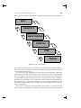
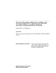
source of the error. The sequence editor to beautifier to syntax checker to compiler to
linker to debugger may be repeated many times before a program even runs, let alone
works and gives correct results (Figure 16.1).
Graphics introduces yet another level of debugging. Graphic debugging is assisted by
the GKS-C language binding and by the error control built into the GKS standards, which
can echo function names and the values passed to them on an ongoing basis. The actual
graphics created are also useful debugging tools. Blank screens often mean an error in the
transformational geometry involved, while errors with primitives and attributes can generate graphics better suited to the walls of the Museum of Modern Art than to cartography.
Once a program has been written and debugged, it is time to return to the documentation and program purpose to check and verify the program. First, the program should
be tested with a small test data set for which the results are known. Few such data sets
exist in cartography, so checking with hand calculators is often in order. Attention should
be given to special case exceptions to computations, such as taking the square root of negative values or testing for the intersection of vertical, parallel lines.
Once small data sets check out, a real-world cartographic data set should be used.
Special cases should be deliberately introduced into the data to check circumstances that
may not have been foreseen during design. Real data has a habit of introducing these special cases as well as other limitations, such as size restrictions, into the program and testing the program’s design limitations.
Failure of the program at any of these stages may demand going back to a module to
Sec. 16.1 The P rogram ming Environm ent
307
make corrections. It may even be necessary to redesign a whole module, which is possible
EDIT
BEAUTIFY
CHECK SYNTAX
COMPILE
LINK
DEBUG
Figure 16.1 The programming sequence.
only with structured programs. If, at this stage, it is found that the entire program structure is poor, this is a good time to give up, as no number of program “patches” can repair
a poor overall structure or logic.
As a final stage, many programs are optimized. This involves analyzing, often using
other computer programs, each module to see how much time is spent in each function
and at each stage in each function. The most time-consuming tasks are reworked first,
each optimization making the program run faster or use less memory. Some C compilers
and operating environments, such as UNIX, have built-in optimizers and program runtime analyzers (the -O compiler option and the profile program). In other cases, optimization is a painstaking process, with each improvement taking seconds off the run
times for the program.
Having given a description of the programming environment, it goes without saying
that it is critical to cartographic software. Much time will be wasted if the programmer
308
Writing Car tographic Software Chap. 16
avoids using the tools available, tools that are now parts of the typical C programming
environment. A little time invested in learning the sequence used in Figure 16.1 can save
hours of wasted time and can result in much more effective and better constructed computer cartographic software.
The programmer should think first and foremost about the map being produced, then
about the specifics of the programming language in use. Above all, the design should be
organized and planned before a single line of computer code is written. Writing computer
programs and designing them are two entirely different tasks, and the worst place to think
about design is inside three levels of open control statements.
16.2 THE GKS C LANGUAGE BINDING
In some earlier chapters, particularly in the discussion of the symbolization transformation, the GKS standard was presented as a means by which cartographers can write computer programs that produce maps. We saw that the standard can be implemented at
different levels, with different device support and functionality for different levels. We
also saw that the link between programming languages and graphics under the GKS standard is the language binding. The ISO specification of GKS lists standard bindings for
GKS for FORTRAN, Ada, and Pascal. Because the C programming language has only
recently been revised into an ANSI version, there is as yet no standard C language binding to GKS. This does not mean, however, that none exists, merely that there are some
differences in bindings between the products of different software vendors.
Fortunately, the GKS standard is quite general when it comes to the major source of
differences, that is , the naming of functions. Function names are listed by English language names rather than GKS function names. Figuring out a function name for a different binding, or even transporting a piece of mapping software between computers or
programming languages, often consists therefore of translating the names of functions
and assuring that arguments in the lists passed to the functions are consistent. A convention used by some vendors for C functions is to use the full rather than abbreviated function names, replacing blanks with underscores ( _ ). On some computers, especially
microcomputers, there is a need to abbreviate due to DOS name limitations or limitations
on the linking capabilities of C compilers. In this discussion, the simplest form of the
name will be given.
A C language binding can be thought of as a set of predefined C libraries that contain
all of the functions necessary to use the standard. The functions break down into those
that manage primitives and attributes, those that handle interaction with the user, those
that control the workstation, those that perform transformations, those that manage segments and the metafile, those that manage errors, and those that allow the programmer to
query GKS to establish any of the above.
In all, this makes several hundred functions, because for every primitive, attribute,
and interaction function there is a corresponding query function. For example, the function
set_fill_area_color_index()has
a
parallel
GKS
function
inquire_fill_area_color_index(). There is a formal structure for the use of
GKS functions. The sequence applies for all GKS levels and implementations. The first
GKS operation that a program must perform is to open GKS. This performs an initializa-
Sec. 16.2 The GKS C Language Binding
309
tion of the software on this system for this application. The function used is
open_gks(). This function sometimes uses as a parameter the name of a file that GKS
will use to write GKS error messages. The file should be opened in write mode by the
user’s program and the value passed should be a pointer to type FILE.
The next stage is to open the workstation. This is accomplished using the function
open_workstation(). Arguments should include an integer identifier for the workstation to be used in successive workstation calls, and a unique number or text string that
identifies the type of workstation to GKS. This number is provided with the GKS language binding, and sometimes with the specific device driver installed.
Examples from Sun Soft’s SunGKS are ws_type values of "postscript",
"hpgl", and "xgl_tool" for a PostScript, HPGL, and a generic X-windows window
respectively. Once opened, the workstation should be activated, or made ready for interaction, using the function activate_workstation(). This function simply uses
the workstation identifier given to open_workstation().
The “digital canvas” is now ready. The programmer can establish the normalization
transformation(s), read any data required, and set any attributes, and is then ready to
draw. If no segments need to be defined, the primitives are simply included in the order
used. To draw and save primitives in a segment, the function call open_segment() is
used to create a new segment, which includes all primitives and their attributes until the
close_segment() function is used. Once defined, segments can be redrawn, renamed, copied between workstations, or written into the metafile. To redraw the entire
map, the function call redraw_all_segments() could be used.
The way back out of the GKS system is the reverse of the way in. After all segments
have been closed, the workstation can be cleared using clear_workstation(), deactivated using the GKS function call deactivate_workstation(), and closed using close_workstation(), and finally GKS can be shut down using
close_gks(). The GKS system also provides an immediate error exit from GKS so
that the programmer can escape from errors elegantly without exiting the graphics levels,
using emergency_close_gks().The sequence is illustrated in Function 16.1.
Few differences exist between bindings, with one exception. Many of the C language
bindings use single-variable parameters as function arguments. This method follows
closely the FORTRAN standard. A line, for example, could be sent to a line drawing
(polyline) function using
polyline (number_of_points, &x[0], &y[0]);
This provides the function with the number of points in the vectors x and y, and the starting addresses of the points. Alternatively, at least one major GKS binding uses a structure
of type POINT and instead passes the address of the entire structure to the GKS function.
Each GKS C binding implementation has its own details. Usually, there is a large
header file, often called gks.h, which contains all the values of the function arguments
in a definition header file, so that, for example, color number 6 on a specific device is
predefined as
#define RED 6
Writing Car tographic Software Chap. 16
310
Function 16.1
/* Program gksbasic : Demonstrate GKS open/close
/* kcc 12-93 Function 16.1
*/
#include <gks/ansicgks.h>
#include “cart_obj.h”
main()
{
Gchar *conn = NULL;
Gchar *wstype = “postscript”;
Gws ws = 1;
/* Open up GKS */
if (gopengks(stdout, GMEMORY))
exit();
/* Open the workstation */
gopenws(ws, conn, wstype);
/* Activate the workstation */
gactivatews(ws);
/*
* Generate a map
*/
/* Deactivate the workstation */
gdeactivatews(ws);
/* Close the workstation */
gclosews(ws);
/* Close down GKS */
gclosegks();
}
Also, different implementations split the libraries up differently. Sometimes the language
binding is separate from the main GKS library. This must be taken into account when
compiling and linking C programs.
New GKS implementations, language bindings, and device drivers become available
frequently. Trade journals, the so-called glossies, and graphics conventions are good
Sec. 16.3 Wr iting Your Own Mapping Program
311
sources of information about these changes. In addition, several GKS implementations
are now appearing as shareware. Although these versions are unlikely to support the more
exotic computers and graphics devices, the more common ones may be found.
In addition, several companies now make add-on software packages built over the
GKS. In a few cases, these systems support advanced mapping functions. Other GKS implementations are very low level (0b, for example), do not support many interactive functions, and allow output only to the metafile. These versions come with metafile
translators, which convert the metafiles into the device-specific graphics calls of a great
number of different graphics devices. Among the most popular are translations to PostScript for output on laser-jet printers or to protocols of desktop publishing packages, allowing the output from computer programs to be pasted directly into a paper, article, set
of documentation, or even a textbook. Other packages, for example CorelDraw! and IslandDraw, allow metafiles in CGM format to be opened for use and editing.
16.3 WRITING YOUR OWN MAPPING PROGRAM
Assuming that you have read much of this book, have read about the C programming language, understand cartographic data structures, and have gone through the software design process described above, how do you actually go about writing a computer program
to generate a map? During the design process, you have asked yourself what kind of map
you wish to produce. You have blocked out a set of modules, which can do any necessary
input, structure the data, perform any necessary transformations, and then generate the
map. The next and most important step is to write the program.
First, you should carefully research the various C compilers available to you. The
newsstand microcomputer journals contain large amounts of information to assist in deciding which compiler to buy. If you have access to a larger computer, see if the C language is available and how it is supported. If the computer runs the UNIX operating
system, then many of the tools available as part of the programming environment discussed above are available. UNIX can also run on many microcomputers and is the most
common workstation operating environment.
Do not start writing programs until you are familiar with the language. When you do,
make lots of deliberate mistakes and see how the various parts of the programming environment react to them. If C is your first language, then as mentioned in Chapter 15, you
should seek out instruction from a computer scientist. If you are coming to C from Pascal
or a similar language, you should have very few problems, but you should find an appropriate C language tutorial and work carefully through it. Pascal programmers should not
be tempted to rewrite C to look like Pascal (although it is possible). Although many of
the concepts from languages like FORTRAN will help in the conversion, it is better to
learn the structured approach from scratch.
A feature that eventually becomes the source of many errors in C programs is the distinction between the types of variables. The C language supports integers (unsigned,
short, regular, and long), characters, floats, and doubles, and although variables must be
assigned types exclusively, type conversions are not automatic. For example, to make a
floating point (real) equivalent of the integer 5, it is not enough simply to assign the value.
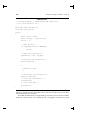
The type should be explicit in the statement also. This is illustrated in the Function 16.2
312
Writing Car tographic Software Chap. 16
Function 16.2
/* ========================================
/* Remember to explicitly perform type
/* conversions in C, otherwise beware!
/* ======================================== */
#include <stdio.h>
main() {
int an_integer = 5;
float a_float;
printf("Integer value is %d\n",an_integer);
a_float = an_integer / 2;
printf("Halved without type conversion the value
is %f\n",a_float);
a_float = (float) an_integer / (float) 2;
printf("Halved with correct type conversion the
value is %f\n",a_float);
}
One of the best ways to learn about computer cartographic programming is to study the
programs written by other cartographers. The list of available sources is short, but it is
growing steadily. Cartographers have been slow to publish their computer programs in a
form suitable for use by others. As a result, many cartographers have duplicated the work
of others without even having the ability to compare the two results.
The programs presented in this book are not complete programs in themselves, but are
building blocks around which more useful computer programs may be constructed. In
most cases, writing a computer program using these functions will involve reformatting
some existing digital cartographic data, entering the data into a programming data structure appropriate to the task, performing any necessary cartographic transformations, and
producing a map. The cartographic transformations may involve implementing an algorithm, perhaps one published with a descriptive paper or journal article.
If the programming is done effectively, each of these tasks can be performed by one
or more program modules. Remember that these modules should become your own personal library of cartographic functions, and that, for best effect, they should be shared
freely with your friends and any other interested persons.
The best way to find weaknesses and errors and to optimize the code is to release programs to other users. Users will expect information such as a manual, and installation details. Also remember, however, that as a user of computer cartographic software you are
under an assumed obligation to report problems, errors, and weaknesses to the author of
any piece of software, for without this feedback, no improvement will take place. It is
also entirely appropriate to report more favorable items of news!
Sec. 16.4 Car tographic Software and the User Interface
313
16.4 CARTOGRAPHIC SOFTWARE AND THE USER INTERFACE
The success or failure of a piece of cartographic software is determined not by innovation, sophistication, or accuracy, but instead by usability. Many excellently written and
designed computer programs have been passed over entirely because they lack the elements that make the capabilities of the program accessible to the user. The usability of
most software, and this includes computer cartographic software, is therefore strongly determined by the user interface of the program. The user interface is the entire set of means
by which the user communicates with software to achieve a specific mapping purpose.
In the early days of computer cartography, most software that produced maps ran in
batch mode. The means of interaction with the program was by supplying a set of parameters in a file (or even on punched cards) that were read and acted upon by the software.
Information could include the names of files, the number of data points in a file, the precise format of an input record, or the numbers of options listed in the documentation. Although batch processing was capable of generating maps, errors were common, since the
map output came at the end of a long sequence of operations which happened quite slowly, often overnight.Even generating a map could take several days, but debugging the
software for mapping could take weeks or months.
As interactive computer systems became commonplace, many computer mapping
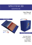
systems moved to interactive processing. The earliest user interface in such an environment was the command-driven program. An example is MicroCAM (Figure 16.02).A
command-driven program reads one command from the user at a time, and acts upon it
either immediately or when a general “action” command is given. Commands usually involve a keyword, such as PLOT or READ, and are followed by a list of values that supply
parameters to the program. For example, to read a grid data file, the command
READ "Input_file" 200 300 I
could be used to read a grid of integers from file Input_file with 200 rows and 300
columns. Note that these commands can be placed together into a file and submitted together in batch mode, implying that command mode contains a batch mode.
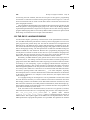
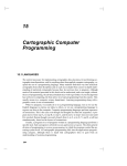
The next level of sophistication in terms of the user interface is to provide a menu in
which commands can be selected by number or letter. Figure 16.3 shows a typical menu
for a computer mapping program. Using a menu, selections can be chosen by entering a
number instead of the name of the option, in the same way that you can order from a Chinese menu by asking simply for “number 6” instead of La Zi Ji Ding. Many menu systems
also allow the name of the command to be typed, thus supporting command lines also.
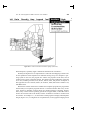
Increasingly, operating systems are taking advantage of the ability of computer programs to use windows. Windows are areas of the screen where interaction can take place
or where graphics can be generated. A windowing system allows the windows to be
moved, resized, or selected to be visible, often with the use of a mouse (Figure 16.4).
Selections can be made by moving the mouse to a header and pulling down the menu,
or the next menu level, and by holding the mouse button down and moving the mouse.
Menus can also appear on the screen at the appropriate time during the execution of the
Writing Car tographic Software Chap. 16
314
Figure 16.2 A command-line driven software package (MicroCam).
{Terrain_Mapping}
TRANSFORMATION OPTIONS
m
w
f
i
n
r
s
a
h
t
c
u
d
q
next menu
write array to a file
filter array data
isopach
invert array
resample array
subsample array
slope/aspect
analytical hill shading
linear trend surface
Convert feet to meters
Unravel an array
Double an array
Quit
** Select option number :t
Figure 16.3 A menu-driven software package (Terrapin: See the companion disk).
Sec. 16.4 Car tographic Software and the User Interface
315
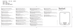
Figure 14.05 A Full GUI Supported Software Package (xv)
Figure 16.4 A window and menu-based software package (MacChoro).
program, the so-called pop-up menu. The windows environment has been popularized by
microcomputers, especially Apple’s Macintosh and Microsoft’s Windows.
Probably the highest level of sophistication is achieved when mapping software uses
all the capabilities of the Graphical User Interface running on top of a computer’s operating system. In this case, the program can “inherit” the properties of the GUI, such as
window colors, button, and menu formats. This allows all of the capabilities of the GUI
to be used, including windows,icons, menus, buttons, dials, and pointers. Examples of
this approach are Sun’s SUNOS, Solaris, X-windows, Motif, Microsoft’s Windows NT,
and IBM’s OS/2.
Because the window functions are callable from computer programs, the programmer
has the ability to incorporate programs that use a consistent interface that is easy for all
users, because it embodies concepts which are common between computers. Furthermore, many vendors of these operating system GUIs support GKS, so that GKS calls to
locator devices make calls to the mouse, and the “workstation” becomes a window such
as an Xterm. An example is xv, an X-windows–based program to display and manipulate
images (Figure 16.5). At a higher level of sophistication, several graphics languages and
316
Writing Car tographic Software Chap. 16
Figure 16.5 A full GUI software package (xv). XV is copyright 1993 by John Bradley.
Used with permission.
toolboxes now support GUI-independent programming, so that a generic program is
“compiled” with a “binder” to a particular GUI such as MacIntosh, Windows, or Motif.
For computer cartographic programs, it is important that the means of interaction with
the user be kept in mind at all times. Modular and flexible programs make it easy to use
one command system during software development and another when the program is finished. A better approach, however, is to write the user interface first. The entire user interaction system can then be debugged, tested, and refined to make the program more
“friendly” before the program even works. For this purpose, many large programs are
first written with “function stubs,” one- or two-line functions that simply report that they
were called in the right place and with the correct arguments. Producing a “skeleton” program in this way makes working on a large program much easier and also allows several
people to work on a program at the same time.
The user interface is the last challenge facing the analytical and computer cartographer. As we have seen, the cartographer of today must have an understanding of the hardware and software tools of computer cartography. He or she must understand
cartographic data, cartographic data structures, and the programming mechanisms by
which they can be manipulated. The analytical cartographer must understand cartographic transformations and be able to use the power of computer programming and the programming environment to achieve a higher understanding of maps and mapping.
It is the user interface, however, that in the future will determine how computer mapping systems relate to the vast number of users who make up the rest of the world. If cartography is to move away from being a discipline in which a practitioner disappeared for
Sec. 16.5 References
317
a time and then delivered a map, if cartography is to become democratic enough to place
the production of maps into the hands of the noncartographer, then we must begin by
writing mapping software that is usable. This means effective user interfaces and meaningful assistance with decision-making, and it means that much well-written software remains to be produced.
The opportunities presented by the wealth of digital cartographic data now becoming
available are extraordinary. How effective this revolution in cartography will be in solving the problems of our world, however, depends on a new generation of analytical and
computer cartographers.
16.5 REFERENCES
Enderle, G., K. Kansey and G. Pfaff (1984). Computer Graphics Programming: GKS-the Graphics Standard. Symbolic Computation, New York: Springer-Verlag.
Foley, J. D., and A. VanDam (1982). Fundamentals of Interactive Computer Graphics.
Reading, MA: Addison-Wesley.
Hearn, D., and M. P. Baker (1986). Computer Graphics. Englewood Cliffs, NJ: Prentice
Hall.
Johnson, N. (1987). Advanced Graphics in C: Programming and Techniques. Berkeley,
CA: Osborne McGraw-Hill.
Myler, H. R., and A. R. Weeks (1993). Computer Imaging Recipes in C. Englewood
Cliffs, NJ: Prentice Hall.
Kernighan, B. W., and D. M. Richie (1988). The C Programming Language. 2d ed. Prentice-Hall Software Series, Englewood Cliffs, NJ: Prentice-Hall.
Lamb, D. A. (1988). Software Engineering: Planning for Change. Englewood Cliffs, NJ:
Prentice Hall.
Press, W. H., B. P. Flannery, S. A. Teukolsky, and W. T. Vetterling (1988) . Numerical
Recipes in C: The Art of Scientific Computing. New York: Cambridge University Press.