1
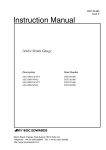
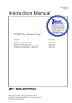
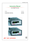
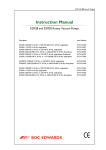
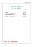
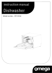
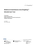
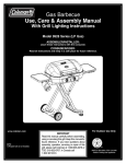
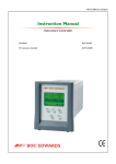
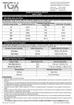
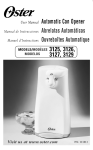
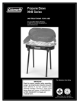
D048-50-880
Issue C
Instruction Manual
Active Ion Gauge
Description
Item Number
AIGX - S - NW25
AIGX - S - DN16CF
AIGX - S - DN40CF
D048-50-000
D048-51-000
D048-52-000
Manor Royal, Crawley, West Sussex, RH10 2LW, UK
Telephone: +44 (0) 1293 528844 Fax: +44 (0) 1293 533453
http://www.bocedwards.com
CONTENTS
Section
Title
Page
1
1.1
1.2
INTRODUCTION
Scope and definitions
Description
1
1
1
2
2.1
2.2
2.3
2.3.1
2.3.2
2.3.3
2.3.4
2.3.5
2.3.6
2.4
TECHNICAL DATA
Mechanical data
Performance, operating and storage conditions
Electrical data
Electrical supply
Output signal
Gauge and degas enable
Set-point
Gauge identification
Electrodes
Materials exposed to vacuum
4
4
4
4
4
4
5
5
5
5
5
3
3.1
3.2
3.3
3.3.1
3.3.2
7
7
7
7
8
3.3.3
INSTALLATION
Unpack and inspect
Fit the AIGX to the vacuum system
Electrical connections
Connect to BOC Edwards AGC
Connect to your own supply and
control equipment
Maximum cable length
8
10
4
4.1
4.2
4.2.1
4.3
4.4
4.5
4.6
4.7
4.8
4.9
4.10
OPERATION
Enable and disable the AIGX
Pressure measurement
Calibration in different gases
Emission current
Degas the AIGX
Over-pressure protection
Filament selection
LED status
Set-point adjustment
Error indication
Bakeout
11
11
12
12
14
14
14
15
15
15
16
16
Active Ion Gauge
i
Section
Title
Page
5
5.1
5.2
5.3
5.4
MAINTENANCE
Fault finding guide
Replace the body tube
Replace the internal fuse
Calibration service
18
18
19
19
20
6
6.1
6.2
STORAGE AND DISPOSAL
Storage
Disposal
21
21
21
7
7.1
7.2
7.3
SPARES AND ACCESSORIES
Introduction
Spares
Accessories
22
22
22
23
RETURN OF BOC EDWARDS EQUIPMENT
Illustrations
Figure
1
2
3
4
5
6
Title
Page
General view of the AIGX (NW25 version)
3
Dimensions (mm)
6
Schematic diagram of recommended electrical connections 9
Pressure output signal of AIGX
13
Separate the electronics housing from the body tube
17
Fuse replacement
20
Tables
Table
1
2
3
4
5
6
ii
Title
Page
Pins on the AIGX connector
Maximum recommended cable length
Gas calibration factors for various gases
LED status
Error indication
Fault finding guide
8
10
12
15
16
18
Active Ion Gauge
1
INTRODUCTION
1.1
Scope and definitions
This manual provides installation, operation and maintenance
instructions for the BOC Edwards Active Ion Gauge (AIGX). You must
use the AIGX as specified in the manual.
Read this manual before you install and operate the AIGX. Important
safety information is highlighted as WARNING and CAUTION
instructions; you must obey these instructions. The use of WARNINGS
and CAUTIONS is defined below.
WARNING
Warnings are given where failure to observe the instruction could
result in injury or death to people.
CAUTION
Cautions are given where failure to observe the instruction could
result in damage to the equipment, associated equipment or process.
The units used throughout this manual conform to the SI international
system of units of measurement.
The following symbols appear on the AIGX:
Warning (refer to accompanying documents)
From August 2005, BOC Edwards will offer European
customers a recycling service.
1.2
Description
The AIGX is an ion gauge head and gauge controller in a single compact
unit. The gauge operates as a hot filament ionisation gauge, in which the
pressure is measured indirectly as a function of the current.
Active Ion Gauge
1
The measurement range of the AIGX is 5 x 10 -10 to 5 x 10⁻² torr
(6.6 x 10⁻¹⁰ to 6.6 x 10⁻² mbar). Three types of vacuum connections are
available: DN16CF, DN40CF and NW25.
The AIGX requires a 14.5 - 30 V d.c. power supply; it has a 0 to 10 V d.c.
analogue output which is related to pressure. The AIGX is compatible
with the BOC Edwards Active Gauge Controller (AGC). Alternatively,
you can use an independent power supply and you can read the output
signal with a voltmeter or analogue to digital converter.
An 8-way electrical connector socket on the AIGX (Figure 1, item 1) is used
to connect the AIGX to your AGC or electrical supply and voltmeter.
Electrical cables fitted with suitable connectors are available as
accessories. A gauge identification signal is available on the electrical
connector: this signal is used by BOC Edwards AGC’s to identify which
type of active gauge is connected.
The AIGX is supplied with two filaments. A switch on top of the gauge
selects between filament 1 and 2 (Figure 1, item 2).
There are two levels of emission currents: 0.1 and 1 mA. The gauge will
automatically select 1 mA emission current at low pressure, and 0.1 mA at
high pressure.
A protection circuit is built into the gauge to prevent operating the gauge
-2
at pressures higher than 5 x 10 torr.
The AIGX can be degassed using the degas feature. During degas, the
grid voltage is 500 V and the emission current is 10 mA. The degas is
inhibited at high pressure. The maximum duration of degas is three
minutes, after which the gauge returns automatically to its normal mode.
The AIGX has a set-point facility. The set-point signal is an open collector
transistor output, which is on when the pressure measured by the gauge
is below a preset pressure. The pressure at which the set-point operates
can be adjusted using the set-trip switch on the top of the gauge (Figure 1,
item 3).
The AIGX is fitted with a status LED (Figure 1, item 4) . This LED indicates
the operating status of the gauge.
2
Active Ion Gauge
4
1
3
2
5
1.
2.
3.
Electrical connector
Filament select switch
Set trip switch
4.
5.
Status LED
Vacuum flange
Figure 1 - General view of the AIGX (NW25 version)
Active Ion Gauge
3
2
TECHNICAL DATA
2.1
Mechanical data
Dimensions
Mass
AIGX-S-NW25
AIGX-S-DN16CF
AIGX-S-DN40CF
Volume of gauge tube
Enclosure rating
2.2
Bakeout temperature
Maximum operating altitude
Maximum internal pressure
Pressure measurement range
2.3
Electrical data
2.3.1
Electrical supply
Voltage
Internal fuse
Maximum power consumption
Operating
Degas
Electrical connector
0 to 40 °C
-30 to 70 °C
90% RH (non-condensing)
up to 31 °C reducing to
50 % RH at 40 °C
200 °C (with electronics
removed)
2000 m
10 bar absolute
5 x 10 -10 to 5 x 10⁻² torr
(6.6 x 10⁻¹⁰ to 6.6 x 10⁻² mbar)
+14.5 V to +30 V d.c.
1 A (T)
7W
14 W
FCC 68 (RJ45)
Output signal
Measurement range
Gauge disabled
Emission error
Over-pressure trip
Minimum load impedance
4
260 g
300 g
510 g
21 cm3
IP30
Performance, operating and storage conditions
Ambient temperature
operation
storage
Ambient humidity
2.3.2
See Figure 1
0.7 V to 8.7 V
9.0 V
9.5 V
9.7 V
10 kΩ
Active Ion Gauge
2.3.3
Gauge and degas enable
Control sense
Active level
2.3.4
Active low
< 1.5 V
Set-point
Trip level
0.6 V to 8.8 V
Hysteresis
500 mV
Set-point output load rating
30 V d.c., 100 mA max
Back EMF suppression diode *
Min surge rating
1A
Min reverse voltage rating
100 V
* required when you use an external d.c. relay connected to the
set-point output
2.3.5
Gauge identification
Identification resistance
2.3.6
162 kΩ
Electrodes
Emission current
Normal
Degas
Grid voltage
Normal
Degas
Filament bias voltage
Collector voltage
2.4
0.1 or 1 mA
10 mA
180 V
500 V
+ 30 V
0V
Materials exposed to vacuum
Collector
Grid
Filament
Body
Feedthrough
Active Ion Gauge
Tungsten
Tantalum Pt Clad Mo
Yttria coated iridium
Stainless Steel
Stainless Steel and UHV compatible,
glass/ceramic
5
A
A
NW25
85
DN16CF
106
DN40CF
98
Figure 2 - Dimensions (mm)
6
Active Ion Gauge
3
INSTALLATION
3.1
Unpack and inspect
Remove all packing materials and protective covers and check the AIGX .
If the AIGX is damaged, notify your supplier and the carrier in writing
within three days; state the Item Number of the gauge together with your
order number and your supplier’s invoice number. Retain all packing
materials for inspection. Do not use the AIGX if it is damaged.
If the AIGX is not to be used immediately, replace the protective covers.
Store the AIGX in suitable conditions as described in Section 6.
3.2
Fit the AIGX to the vacuum system
The AIGX can be mounted in any orientation. To avoid the build-up of
debris or condensable material in the body tube of the AIGX (which will
probably cause pressure measurement errors), we recommend that you
install the AIGX vertically with the flange facing down.
Use a copper gasket and screws to connect the DN16CF and DN40CF
flanges of the AIGX to a similar flange on your vacuum system. Use
an ‘O’ ring / centring-ring or Co-Seal and metal clamp to connect the
NW25 flange of the AIGX to a similar flange on your vacuum system.
Note:
3.3
’O’ rings are not recommended for systems where UHV pressures
are required.
Electrical connections
WARNING
The AIGX must be connected to an earthed (grounded) vacuum
system. For gauges with a NW25 flange, a conductive metallic
clamping ring must be used.
WARNING
If the AIGX malfunctions, the AIGX pressure output may be
incorrect. If such a failure could result in damage to equipment or
cause injury to people, you must install a suitable control system to
indicate the failure and, if necessary, to close down your process
system.
Active Ion Gauge
7
3.3.1
Connect to BOC Edwards AGC
Connect the AIGX to the AGC using a cable which is terminated in
suitable connectors. Suitable cables are available from BOC Edwards.
Refer to Section 7.3.
3.3.2
Note:
Your AGC must have a version of software that is compatible with
the AIGX. If the AGC display shows ??? when the AIGX is
plugged in, then an upgrade to the AGC software is required.
Please contact BOC Edwards.
Note:
For cable lengths exceeding 10 m, cables with a larger conductor
cross-section are required.
Connect to your own supply and control equipment
Note:
Do not connect the electrical supply common (pin 2) to the signal
common (pin 5). If you do, the AIGX pressure output signal will
be inaccurate.
A schematic diagram of the recommended electrical connections to the
AIGX is shown in Figure 3.
The pins on the AIGX connector are used as shown in Table 1. The
specification of the electrical supply, d.c. relay and back EMF suppression
diode are given in Section 2.
Pin No.
1
2
3
4
5
6
7
8
Use
Supply positive
Supply common
Signal output
ID resistor
Signal common
Degas enable
Gauge enable
Set-point output
Table 1 - Pins on the AIGX connector
The connection to Pin 8 is optional. Make the connection to Pin 8 if you
want to connect the set-point output signal to a d.c. relay. You must
connect a suppression diode between pins 8 and 1 to protect the AIGX
from transient voltage generated when the d.c. relay is switched off.
Connect a switch between pins 7 and 2 to enable and disable the gauge.
Connect a switch between pin 6 and 2 to enable and disable the degas
function.
8
Active Ion Gauge
KEY
A
B
C
D
E
F
G
AIGX connector (socket)
Cable electrical (plug)
Degas enable switch
Gauge enable switch
Back EMF suppression diode (optional)
D.C. relay (optional)
View of AIGX connector
Figure 3 - Schematic diagram of recommended electrical connections
Active Ion Gauge
9
3.3.3
Maximum cable length
The maximum cable length is dependent on the conductor cross-section
and the supply voltage used. The following maximum cable lengths are
recommended:
Conductor cross-section
24 awg
28 awg
24 V Supply 15 V Supply
30 m
10 m
0.5 m
1m
Table 2 - Maximum recommended cable length
The common mode signal voltage (that is, the voltage between signal
common and supply common) could be as much as 2.5 V with long cables
due to the voltage drop in the supply cable. You should ensure that the
signal voltage measurement will operate correctly.
10
Active Ion Gauge
4
OPERATION
WARNING
Do not use the AIGX to measure the pressure of explosive or
flammable gases or mixtures.
WARNING
During operation, the surface of the ion gauge tube might become
hot. To avoid risk of injury, do not touch the tube whilst the gauge is
operating. Switch off the gauge and allow to cool down for few
minutes before handling.
WARNING
Disconnect the electrical supply cable from the AIGX before you
remove the AIGX from the vacuum system. High voltages are
generated inside the AIGX.
4.1
Enable and disable the AIGX
CAUTION
The gauge should not be operated at pressures higher than
5 x 10 -2 torr (6.6 x 10⁻² mbar). Operating the AIGX at high pressures
may reduce the lifetime of the filament.
If you are using the AIGX with an AGC, refer to the AGC instruction
manual for details of how to enable the AIGX. Alternatively, to enable
(switch on) the AIGX, connect pin 7 to pin 2. To disable (switch off) the
AIGX, disconnect pin 7 from pin 2.
When the AIGX is enabled, the output signal will remain at 9.0 V whilst
the emission current is being stabilised. This will take typically 5 seconds
(may be longer at lower pressures). After this time the output signal will
indicate pressure. If an error occurs, then the output signal will indicate
the error.
Active Ion Gauge
11
4.2
Pressure measurement
If you are using an AIGX with an AGC, the pressure measurement is
shown on the AGC display. Otherwise, convert the output signal to
pressure using the following equation:
P = 10 (V - 10) torr
P = 10 (V - 9.875) mbar
P = 10 (V - 7.875) Pa
where V is the measured voltage in volts. Refer to Figure 4. This formula
is valid for the range 0.7 V to 8.7 V.
4.2.1
Calibration in different gases
The equation given in Section 4.2 is for air or nitrogen only. For other
gases, the indicated pressure has to be multiplied by a gas calibration
factor (GCF).
The following table list the gas calibration factor for most commonly used
gases.
Gas
GCF
Helium
Argon
Neon
Krypton
Xenon
Hydrogen
Oxygen
Carbon Monoxide
Carbon Dioxide
5.7
0.75
3.3
0.5
0.35
2.4
1
1.15
0.7
Table 3 - Gas calibration factors for various gases
12
Active Ion Gauge
8
7
6
5
4
3
2
1
0
1E-10
1E-9
1E-8
1E-7
1E-6
1E-5
1E-4
1E-3
1E-2
1E-1
1E+0
1E+1
Indicated Pressure
mbar
torr
Pascal
Figure 4 - Pressure output signal of AIGX
Active Ion Gauge
13
4.3
Emission current
To increase the life time of the filament, the two levels of emission
currents are automatically controlled by the gauge. As the pressure goes
-5
down, the emission current changes from 0.1 mA to 1mA at 2 x 10 torr
(2.6 x 10⁻⁵ mbar). As the pressure goes up, the emission current
changes from 1 mA to 0.1 mA at 5 x 10⁻⁵ torr (6.6 x 10⁻⁵ mbar).
4.4
Degas the AIGX
CAUTION
You must degas the AIGX regularly. Failure to do so will affect the
performance and reduce the lifetime of the gauge.
During use in contaminating environments the gauge electrodes become
coated in insulating layers, eventually resulting in premature failure of
the product. This can be prevented by regular use of the degas feature.
Typically, degas will be required on a weekly basis although the interval
will depend on the level of contamination.
The degas operation is also recommended if measurement of low
pressure are required.
During degas, the grid will be heated to high temperature, sufficient to
remove absorbed gases and some contamination.
Degas the AIGX when the pressure is below 1 x 10⁻⁵ torr (1.3 x 10⁻⁵ mbar).
The degas is inhibited when the pressure is above 1 x 10⁻⁴ torr
(1.3 x 10⁻⁴ mbar). The gauge will automatically return to the normal
operation mode after 3 minutes.
If you are using the AIGX with an AGC or a TIC controller, refer to the
AGC or TIC instruction manual for details of how to degas the AIGX.
Otherwise, to enable degassing of the AIGX, connect pin 6 to pin 2.
4.5
Over-pressure protection
The gauge will automatically switch off when the measured pressure
rises above 5 x 10⁻² torr (6.6 x 10⁻² mbar). If this occurs then the signal
output and LED status will indicate over-pressure trip. Refer to
Section 4.9.
14
Active Ion Gauge
4.6
Filament selection
The AIGX has two filaments, 1 and 2. To select either of these filaments,
use the sliding switch at the top of the gauge. Make sure that the gauge is
turned off before switching between filaments.
4.7
LED status
The AIGX is fitted with a tri-coloured LED which can be used to monitor
the status of the gauge according to the following table:
Colour
Status
Off
Amber
Green/Amber (alternating)
Green
Green (slow flashing)
Red (flashing)
Red
No power to the gauge or malfunction
Power on, gauge disabled
Emissions start-up
Emission on
Degas on
Emission error
Over-pressure trip
Table 4 - LED status
4.8
Set-point adjustment
To read the voltage at which the set-point output signals are activated,
press the required set trip switch (refer to Figure 1) with an appropriate
tool. The output of the gauge will indicate the set trip level for 3 seconds
after which the output will read the normal voltage output.
To adjust the voltage at which the set-point output signal is activated,
press the required set trip switch and hold it down for more than
3 seconds. The set-point voltage will start scrolling upwards. Remove
pressure from the switch as soon as you reach the required trip voltage.
To make a finer adjustment, remove pressure from the set trip switch and
immediately depress the switch as many times as required. Each
depression will increase the set trip voltage by approximately 10 mV.
Refer to Section 4.2 to determine the operating voltage which
corresponds to a given pressure.
If required, the set-point signal can be used to indicate when the gauge is
operating correctly. Adjust the set-point trip level to > 8.8 V. The
set-point output will then be ON when the AIGX is operating normally.
The set-point output will be OFF if the gauge is disabled or if an error
condition is detected.
Active Ion Gauge
15
4.9
Error indication
If an error occurs during operation of the AIGX, then the output signal
and the LED will indicate the error. Refer to Section 5.1 for a fault finding
guide.
Error Condition
Output Signal
Emission error
Over-pressure trip
9.5 V
9.7 V
LED
Red flashing
Red
AGC Display
EM ERR
OVER R
Table 5 - Error indication
If an error is indicated then the AIGX will automatically turn off. You
should disable the AIGX to remove the error indication, and correct the
error. You may then re-enable the AIGX if required.
Note:
4.10
If you are using the AIGX with an AGC, then the AGC will display
an error message and disable the AIGX when an error occurs. In
this case the LED status will return to OFF, and you should view
the AGC display to determine the error.
Bakeout
The AIGX tube can be baked to temperatures up to 200 °C after removing
the electronics housing. Refer to Figure 5 and the procedure in Section 5.2
to remove and refit the electronics housing.
Ensure that the tube has cooled down before refitting the electronics
housing.
16
Active Ion Gauge
1
2
4
2
3
1.
2.
Electronics housing
Fixing screws
3.
4.
Body tube assembly
Locating lugs
Figure 5 - Separate the electronics housing from the body tube
Active Ion Gauge
17
5
MAINTENANCE
WARNING
Disconnect the electrical supply cable before you start any
maintenance. High voltages are generated inside the AIGX.
5.1
Fault finding guide
Symptom
LED Not Lit
Possible Cause
Remedy
Supply connection incorrect Check electrical supply
and connections.
or faulty. Supply polarity
reversed.
Internal fuse blown.
Replace fuse. Refer to
Section 5.3
Over-pressure
trip
The pressure rose too high
whilst the AIGX was
operating.
Reduce the pressure
and re-enable the
AIGX.
Emission error
The AIGX was enabled
when the pressure was too
high.
Reduce the pressure
and re-enable the
AIGX.
Filament contaminated.
Filament open circuit.
Switch to the other
filament. If both
filaments give the error,
replace the body tube.
Refer to Section 5.2.
Electrical supply insufficient Check that supply
to drive the AIGX.
voltage/current
specifications meet
requirement in
Section 2.3.1.
Table 6 - Fault finding guide
18
Active Ion Gauge
5.2
Replace the body tube
Refer to Figure 5 and use the following procedure to replace the body
tube.
1. Turn off the gauge.
2. Switch off the AIGX electrical supply and disconnect the electrical
supply cable.
3. Remove the AIGX from the vacuum system.
4. Using a suitable screwdriver, remove the two M3 screws (item 2)
from the sides of the electronics housing (item 1).
5. Pull the electronics housing (item 1) to remove it from the body
tube assembly (item 3).
6. Fit the new body tube assembly (item 3) to the electronics housing
(item 1). Take care to ensure that the locating lugs (item 4) on the
body tube assembly (item 3) are aligned with the mating recess in
the electronics housing (item 1). Note that the electronics housing
(item 1) can only fit one way round on the body tube assembly
(item 3).
7. Refit the two M3 screws to the sides of the AIGX.
5.3
Replace the internal fuse
If you suspect that the internal fuse has blown, you should check that the
voltage and polarity of the electrical supply are correct before replacing
the fuse.
To replace the fuse refer to Figure 6 and use the following procedure:
1. Switch off the electrical supply and remove the electrical supply
connector from the gauge.
2. Using a suitable screwdriver, remove the four M3.5 screws from the
top of the gauge.
3. Remove the gauge lid, ensuring the pin on the underside of the lid
is not bent.
4. The fuse will now be visible on the PCB. Hold the board down and
then pull the fuse from it’s fuseholder using an appropriate tool
(for example, a small pair of pliers).
Active Ion Gauge
19
5. The replacement fuse is supplied mounted in a fuseholder. Remove
the new fuse from its fuseholder and discard the new fuseholder.
6. Push the new fuse into the fuseholder on the PCB.
7. Refit the gauge lid ensuring that the pin is fitted in the shrouded
earth socket next to the main connector. Refit the four M3.5
screws.
8. Apply power to the gauge and check that the LED is illuminated.
Replacement fuses are available from BOC Edwards. Refer to Section 7.2.
2
1
1.
Fuse holder
2.
Shrouded earth socket
Figure 6 - Fuse replacement
5.4
Calibration service
A calibration service is available for all BOC Edwards gauges. Calibration
is by comparison with reference gauges, traceable to National Standards.
Contact BOC Edwards for details.
20
Active Ion Gauge
6
STORAGE AND DISPOSAL
6.1
Storage
Return the AIGX to its protective packaging and store the AIGX in clean
dry conditions until required for use. Do not exceed the storage
temperature conditions specified in Section 2.
When required for use, prepare and install the AIGX as described in
Section 3.
6.2
Disposal
Disposal of the AIGX in accordance with all local and national safety and
environmental requirements.
Alternatively, you may be able to recycle the AIGX and/or cables; contact
BOC Edwards or your supplier for advice (also see below).
The AIGX and associated cables are within the scope of the European
Directive on Waste Electrical and Electronic Equipment, 2002/96/EC.
From August 2005, BOC Edwards will offer European customers a
recycling service for the AIGX/cables at the end of the product’s life.
Contact BOC Edwards for advice on how to return the AIGX/cables for
recycling.
Active Ion Gauge
21
7
SPARES AND ACCESSORIES
7.1
Introduction
BOC Edwards products, spares and accessories are available from BOC
Edwards companies in Belgium, Brazil, Canada, France, Germany, Great
Britain, Hong Kong, Italy, Japan, Korea, Switzerland, U.S.A, and a world
wide network of distributors. The majority of these centres employ
Service Engineers who have undergone comprehensive BOC Edwards
training courses.
Order spare parts and accessories from your nearest BOC Edwards
company or distributor. When ordering, please state for each part
required:
7.2
•
Model and Item Number of your equipment
•
Serial number (if any)
•
Item Number and description of part
Spares
Description
Electronics housings
AIGX-S
Body tubes
NW25
DN16CF
DN40CF
Spare fuses (pack of 5)
22
Item Number
D048-50-800
D048-50-801
D048-51-801
D048-52-801
D048-50-805
Active Ion Gauge
7.3
Accessories
Cables suitable for use with the AIGX are as follows. These cables are
supplied with 8-way male electrical connectors on both ends. Note that
the 15 m and 30 m cables have a larger conductor cross-section.
Cable length
Item Number
0.5 m
1m
3m
5m
10 m
15 m
30 m
D400-01-005
D400-01-010
D400-01-030
D400-01-050
D400-01-100
D400-05-150
D400-05-300
Description
Item Number
Annealed copper gasket - DN16CF
Hex head nut, bolt and washer kit
- DN16CF
Annealed copper gasket - DN40CF
Hex head nut, bolt and washer kit
- DN40CF
C100-01-270
C100-01-630
Active Ion Gauge
C100-05-270
C100-05-630
23
24
Active Ion Gauge
Form HS1
Return of BOC Edwards Equipment - Procedure
INTRODUCTION
Before returning your equipment, you must warn BOC Edwards if substances you used (and produced)
in the equipment can be hazardous. This information is fundamental to the safety of our Service Centre
employees and will determine the procedures employed to service your equipment.
Complete the Declaration (HS2) and send it to BOC Edwards before you dispatch the
equipment. It is important to note that this declaration is for BOC Edwards internal use only, and
has no relationship to local, national or international transportation safety or environmental
requirements. As the person offering the equipment for shipment, it is your responsibility to ensure
compliance with applicable laws.
P900-70-000 Issue K
GUIDELINES
• Equipment is 'uncontaminated' if it has not been used, or if it has only been used with substances
that are not hazardous. Your equipment is 'contaminated' if it has been used with any substances
classified as hazardous under EU Directive 67/548/EEC (as amended) or OSHA Occupational Safety
(29 CFR 1910).
• If your equipment has been used with radioactive substances, biological or infectious agents,
mercury, polychlorinated biphenyls (PCB’s), dioxins or sodium azide, you must decontaminate it
before you return it to BOC Edwards. You must send independent proof of decontamination (for
example a certificate of analysis) to BOC Edwards with the Declaration (HS2). Phone BOC
Edwards for advice.
• If your equipment is contaminated, you must either:
• Remove all traces of contamination (to the satisfaction of laws governing the transportation of
dangerous/hazardous substances).
• Or, properly classify the hazard, mark, manifest and ship the equipment in accordance with
applicable laws governing the shipment of hazardous materials.
Note: Some contaminated equipment may not be suitable for airfreight.
PROCEDURE
1. Contact BOC Edwards and obtain a Return Authorisation Number for your equipment.
2. Complete the Return of BOC Edwards Equipment - Declaration (HS2).
3. If the equipment is contaminated, you must contact your transporter to ensure that you properly
classify the hazard, mark, manifest and ship the equipment, in accordance with applicable laws
governing the shipment of contaminated/hazardous materials. As the person offering the equipment
for shipment, it is your responsibility to ensure compliance with applicable law. Note: Equipment
contaminated with some hazardous materials, such as semiconductor by-products,
may not be suitable for airfreight - contact your transporter for advice.
4. Remove all traces of hazardous gases: pass an inert gas through the equipment and any accessories
that will be returned to BOC Edwards. Where possible, drain all fluids and lubricants from the
equipment and its accessories.
5. Seal up all of the equipment's inlets and outlets (including those where accessories were attached)
with blanking flanges or, for uncontaminated product, with heavy gauge tape.
6. Seal equipment in a thick polythene/polyethylene bag or sheet.
7. If the equipment is large, strap the equipment and its accessories to a wooden pallet. If the
equipment is too small to be strapped to a pallet, pack it in a suitable strong box.
8. Fax or post a copy of the Declaration (HS2) to BOC Edwards. The Declaration must arrive before
the equipment.
9. Give a copy of the Declaration (HS2) to the transporter. You must tell your transporter if the
equipment is contaminated.
10. Seal the original Declaration in a suitable envelope: attach the envelope securely to the outside of
the equipment package, in a clear weatherproof bag.
WRITE YOUR RETURN AUTHORISATION NUMBER CLEARLY ON THE
OUTSIDE OF THE ENVELOPE OR ON THE OUTSIDE OF THE EQUIPMENT
PACKAGE.
Form HS2
Return of BOC Edwards Equipment - Declaration
Return Authorisation Number:
You must:
•
Know about all of the substances which have been used and produced in the equipment before you complete this Declaration
•
Read the Return of BOC Edwards Equipment - Procedure (HS1) before you complete this Declaration
•
Contact BOC Edwards to obtain a Return Authorisation Number and to obtain advice if you have any questions
•
Send this form to BOC Edwards before you return your equipment
SECTION 1: EQUIPMENT
Equipment/System Name_________________________
IF APPLICABLE:
Part Number _________________________________
Tool Reference Number_________________
Serial Number_________________________________
Process ______________________________
Has the equipment been used, tested or operated ?
Failure Date___________________________
YES
Serial Number of
Replacement Equipment_________________
R Go to Section 2
NO
R Go to Section 4
SECTION 2: SUBSTANCES IN CONTACT WITH THE EQUIPMENT
Are any substances used or produced in the equipment:
•
•
Radioactive, biological or infectious agents, mercury,
poly chlorinated biphenyls (PCBs), dioxins
or sodium azide? (if YES, see Note 1) YES
NO
R
YES R
Hazardous to human
health and safety?
R
NO R
Note 1 : BOC Edwards will not accept delivery of any
equipment that is contaminated with radioactive substances,
biological/infectious agents, mercury, PCB’s, dioxins or
sodium azide, unless you:
•
•
Decontaminate the equipment
Provide proof of decontamination
YOU MUST CONTACT BOC EDWARDS FOR ADVICE
BEFORE YOU RETURN SUCH EQUIPMENT
SECTION 3: LIST OF SUBSTANCES IN CONTACT WITH THE EQUIPMENT
Chemical
Symbol
Substance name
Precautions required (for example,
use protective gloves, etc.)
Action required after a spill,
leak or exposure
SECTION 4: RETURN INFORMATION
Reason for return and symptoms of malfunction _________________________________________________
_________________________________________________________________________________
If you have a warranty claim:
•
who did you buy the equipment from ? _____________________________
•
give the supplier’s invoice number_________________________________
SECTION 5: DECLARATION
Print your name:_________________________________Print your job title:_________________________
Print your organisation:____________________________________________________________________
Print your address:_______________________________________________________________________
Telephone number: ___________________________Date of equipment delivery: ______________
I have made reasonable enquiry and I have supplied accurate information in this
Declaration. I have not withheld any information, and I have followed the Return of
BOC Edwards Equipment - Procedure (HS1).
Signed: _____________________________________Date______________
Note: Please print out this
form, sign it and return the
signed form as hard copy.
P900-71-000 Issue K
_______________________________________________________________________
This page intentionally blank.
EUROPE/UNITED KINGDOM
BOC EDWARDS
Manor Royal
Crawley
West Sussex, RH10 9LW
Tel +(44) 1293 528844
Fax +(44) 1293 533453
AMERICAS
USA HEADQUARTERS
BOC EDWARDS
One Edwards Park
301 Ballardvale Street
Wilmington, MA 01887
Tel +(1) 978 658 5410
Toll Free (USA only) 1800 848 9800
Fax +(1) 978 658 5410
3901 Burton Drive
Santa Clara, CA 95054
Tel +(1) 408 496 1117
Fax +(1) 408 496 1118
1810 West Drake Drive
Suite 101
Tempe, AZ 85283
Tel +(1) 480 777 7007
Fax +(1) 480 777 2244
4117 Commercial Center Drive
Austin, TX 78744
Tel +(1) 512 416 0102
Fax +(1) 512 328 9846
3501 Island Avenue
Philadelphia, PA 19153
Tel +(1) 215 365 8653
Fax +(1) 978 756 6846
U.S. National Sales Center
Mon 8:30 A. M. - 8:00 P.M. EST
Tues 8:30 A. M. - 8:00 P.M. EST
Wed 8:30 A. M. - 8:00 P.M. EST
Thurs 8:30 A. M. - 8:00 P.M. EST
Fri
8:30 A. M. - 6:30 P.M. EST
P800-80-000 Issue K 01A09-010
BELGIUM
BOC EDWARDS
Bergensesteenweg 709
B1600 Sint-Pieters-Leeuw
Brussels
Tel +(32) 2 363 0030
Fax +(32) 2 363 0064
BRAZIL
BOC DO BRAZIL LTDA
Rua Bernado Wrona 222
02710 São Paulo-SP
Brazil
Tel +(55) 11 3952 5000
Fax +(55) 11 3965 2766
CANADA
BOC EDWARDS
5975 Falbourne Street
Mississauga, Ontario L5R3W6
Canada
Tel +(1) 800 387 4076
Fax +(1) 905 501 1225
12055 Cote de Liesse
Dorval, Quebec H9P1B4
Canada
Tel +(1) 514 631 3501
Fax +(1) 514 631 3502
CHINA
BOC TRADING (SHANGHAI)
CO. LTD
23 Fu Te Road(N),
Wai Gao Qiao Free Trade Zone
Pudong, Shanghai, 200131,
PRC, China
Tel +(86 21) 58669618
Fax +(86 21) 58669993
GERMANY
BOC EDWARDS
Ammerthalstraße 36
85551 Kirchheim
Munich
Tel +(49) 89 99 19 18 0
Fax +(49) 89 99 19 18 99
FRANCE
BOC EDWARDS
125 Avenue Louis Roche
92238 Gennevillers, Cedex
Paris
Tel +(33) 1 47 98 24 01
Fax +(33)1 47 98 44 54
HONG KONG S.A.R.
BOC EDWARDS (ASIA)
12 Chun Yat Street
Tseung Kwan O Industrial
Estate
Tseung Kwan O, Kowloon
Hong Kong SAR
Tel +(852) 2372 2640
Fax +(852) 2796 9095
INDIA
BOC EDWARDS
DIVIN. OF BOC INDIA LIMITED
203 Surya Kiran Building
19 Kasturba Gandhi Marg
New Delhi - 110 001
India
Tel +(91) 11 237 33087
Fax +(91) 11 551 0245
ISRAEL
EDWARDS ISRAEL VACUUM LTD
5 Habarzel Blvd
Gat 2000 Industrial Zone
Qiryat Gat 82000
Tel +(972) 8 681 0633
Fax +(972) 8 681 0640
ITALY
BOC EDWARDS
Via Carpaccio 35
20090 Trezzano sul Navigilo
Milan
Tel +(39) 2 48 4471
Fax +(39) 2 48 401638
JAPAN
HEADQUARTERS
BOC EDWARDS
Shwa Shiba Park Building A-3F
2-4-1 Shibakoen Minato-ku
Tokyo, 105-0011
Tel +(81)(0) 3 5470 6530
Fax +(81)(0) 3 5470 6521
KOREA
HEADQUARTERS
SONGWON EDWARDS LTD
5th FL. Daewoo Engineering
Bldg.
Soonae-dong
Bundang-gu, Sungnam City
Kyungki-do, Korea
Tel +(82) 31 716 7070
Fax +(82) 31738 1001
SONGWON EDWARDS LTD
625-7 Upsong-dong
Chunan City
Chungchong Nam-do
Korea
Tel +(82) 41 621 7070
Fax +(82) 41 621 7700
SINGAPORE
BOC EDWARDS (ASIA)
42 Loyang Drive
Loyang Indusrial Estate
Singapore 508962
Tel +(65) 546 8408
Fax +(65) 546 8407
TAIWAN, R.O.C.
EDWARDS TAIWAN LIMITED
No. 434 Chung-hua Road
Toufen Town, Miaoli County
Taiwan R.O.C.
Tel +(886) 37 611422
Fax +(886) 37 611401
PLEASE CONTACT ANY OF THE ABOVE FOR DETAILS OF OTHER SALES AND SERVICE CENTERS IN YOUR AREA.
BOC Edwards is part of BOC Limited. BOC Edwards and the stripe symbol are trade marks of The BOC Group
© BOC Edwards 2004
Publication No. C100-04-895
www.bocedwards.com
[email protected]