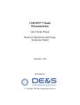
1
A373–10–880 Issue K Original
Instruction Manual
E2M28 and E2M30 Rotary Vacuum Pumps
Description
Item Number
E2M28, 100/200 V, 50 Hz or 100-105/200-210 V, 60 Hz, single-phase
E2M28, 115/230 V, 60 Hz, single-phase
E2M28, 200-240 V, 50 Hz, or 230-240 V, 60 Hz, single-phase
E2M28, 200-220/380-415 V, 50 Hz, or 200-230/460 V, 60 Hz, three-phase
E2M28, 200-240 V, 50 Hz, or 230-240 V, 60 Hz, single-phase (Amphenol)
E2M28, 110/200-240 V, 50 Hz, or 115-120/200-230 V, 60 Hz, single-phase
A373-15-904
A373-15-981
A373-15-903
A373-10-940
A373-16-903
A373-17-984
E2M28-FF, 220/240 V, 50 Hz, or 230/240 V, 60 Hz, single-phase
E2M28-FF, 200-220/380-415 V, 50 Hz, or 200-230/460 V, 60 Hz, three-phase
A373-25-903
A373-21-940
E2M30, 100/200 V, 50 Hz or 100-105/200-210 V, 60 Hz, single-phase
E2M30, 115/230 V, 60 Hz, single-phase
E2M30, 200-240 V, 50 Hz, or 230-240 V, 60 Hz, single-phase
E2M30, 200-220/380-415 V, 50 Hz, or 200-230/460 V, 60 Hz, three-phase
A374-15-904
A374-15-981
A374-15-903
A374-10-940
of Conformity
Declaration
W€,
BOCEdwards,
ManorRoyal,
Crawley,
WestSussexRH102LW,UK
that the product(s)
declareunderour soleresponsibility
E2M28andE2M30RotaryVacuumPumps
A373-10-940 A373-15-981 A374-t0-940
A373-2r-940 A374-15-903 A373-15-904
A374-15-904 A373-16-903 A374-15-981
A373-15-903
A373-25-903
4373-L7-9U
withthe followingstandard(s)
relatesis in conformity
to whichthisdeclaration
document(s)
or othernormative
ENISO12100-2:2003
EN61010-1:2001
EN1012-2:1997
IEC34 Parts1, 5, 8i, 11x: 1991
C22.2No77: t998 #
C22.2No 100:1992#
C22.2No 1010.1:t992 #
UL61010A:2002#
UL1004:1994#
EN13463-1:2001
t
x
3-phasepumpsonly.
l-phasepumpsonly.
#
l-phasepumpsonly.
- BasicConcepts,
for Design.
GeneralPrinciples
Safetyof Machinery
Control,
for Measurement,
for Electrical
Equipment
SafetyRequirements
Use.x
and Laboratory
Part?:
andVacuumPumps- SafetyRequirements,
Compressors
VacuumPumps.
Machines.
for RotatingElectrical
CentralRequirements
Protection.
Motorswith InherentOverheating
MotorsandGenerators.
Control
Equipment
for Measurement
for Electrical
SafetyRequirements
Use,Part1: GeneralRequirements.
and Laboratory
for Laboratory
Use,Part1: GeneralRequirements.
Equipment
Electrical
ElectricMotors.
Atmospheres.
Explosive
Equipment
for Potentially
NonElectrical
in accordance
Thepumpscomplywith EN61010-1wheninstalled
with the pumps.
manualsupplied
withthe instruction
Laboratory.
AuthorityandUnderwriters
Standards
Canadian
of
followingthe provisions
731023/EEC
89/336iEEC
98137/EC
g4lglEc
LowVoltageDirective.
Directive.
Compatibility
Electromagnetic
SafetyDirective.
Machinery
Atmospheres
Explosive
for usein Potentially
Equipment
Only.
(ATEXDirective)(Category3GD)InternalAtmospheres
<
u
-
JD.U"A-:
3 Dgc.engvr
?oo\t
e\ontbilFl^
@
I
Dr,J,D.Watson,
Director
of Technology,
Divisions
Product
Management
Vacuum
Equipment
andExhaust
DateandPlace
undera qualitysysfemregisteredto lSO9001
Thisproducthasbeenmanufactured
^AW BOC EDWARDS
o
c
4
E2M28 and E2M30 Rotary Vacuum Pumps
CONTENTS
Section
Page
INTRODUCTION
Scope and definitions
ATEX directive implications
Description
Gas-ballast
1
1
2
4
4
2
2.1
2.2
2.3
2.4
2.5
TECHNICAL DATA
Operating and storage conditions
Performance
Mechanical data
Lubrication data
Electrical data
5
5
5
6
6
6
3
3.1
3.2
3.3
3.4
3.5
3.6
3.6.1
3.6.2
3.6.3
3.6.4
3.7
3.7.1
3.7.2
3.8
3.9
3.10
3.11
INSTALLATION
Safety
System design
Unpack and inspect
Locate the pump
Fill the pump with oil
Electrical installation: single-phase motors
Introduction
Standard single-phase motors
Amphenol version single-phase motors
110/200-240 V 50 Hz or 115-120/200-230 V 60 Hz single-phase motors
Electrical installation: three-phase motors
Connect the electrical supply to the motor
Check the direction of rotation
Connect the pump inlet
Connect the pump outlet
Gas-ballast inlet connection
Leak test the system
11
11
12
12
13
13
14
14
15
15
15
19
19
20
20
22
22
22
4
4.1
4.1.1
4.1.2
4.1.3
4.2
4.3
4.4
4.5
4.6
4.7
4.8
OPERATION
ATEX directive implications
Introduction
Flammable/pyrophoric materials
Gas purges
Gas-ballast control
Start-up
To achieve ultimate vacuum
To pump condensable vapours
To decontaminate the oil
Unattended operation
Shut-down
23
23
23
23
24
24
25
25
26
26
26
27
Ipsitech 8207(D)–05
1
1.1
1.2
1.3
1.4
Issue K
i
Jul 05
PAGE
i
E2M28 and E2M30 Rotary Vacuum Pumps
Section
PAGE
ii
Page
5
5.1
5.2
5.3
5.4
5.5
5.6
5.7
5.8
5.9
5.10
5.11
5.11.1
5.11.2
5.11.3
5.11.4
5.11.5
5.11.6
5.11.7
5.11.8
MAINTENANCE
Safety information
Maintenance plan
Check the oil-level
Replace the oil
Inspect and clean the inlet-filter
Clean the gas-ballast filter
Clean the motor fan-cover and enclosure
Clean and overhaul the pump
Fit new blades
Test the motor condition
Fault finding
Introduction
The pump has failed to start
The pump fail to achieve specified performance (failure to reach ultimate vacuum)
The pump is noisy
The pump surface temperature is above 100 oC
The vacuum is not maintained after the pump is switched off
The pumping speed is poor
There is an external oil leak
29
29
29
30
30
31
32
33
33
33
33
33
33
33
34
34
34
35
35
35
6
6.1
6.2
STORAGE AND DISPOSAL
Storage
Disposal
37
37
37
7
7.1
7.2
7.3
7.4
7.4.1
7.4.2
7.4.3
7.4.4
7.4.5
7.4.6
7.4.7
7.4.8
7.4.9
7.4.10
7.4.11
7.4.12
7.4.13
7.4.14
7.4.15
SERVICE, SPARES AND ACCESSORIES
Introduction
Service
Spares
Accessories
Introduction
Inlet Catchpot
Inlet Dust Filter
Inlet Desiccant Trap
Inlet Chemical Trap
Outlet Mist Filter
Solenoid Operated Pipeline Valve
Foreline Trap
Vibration Isolators
Oil Drain Extension
Pump Inlet Adaptor
Flexible Bellows
Pump Outlet Adaptor
Gas Ballast Banjo/Elbow Assembly
Gas Ballast Valve
39
39
39
39
40
40
40
40
40
40
40
42
42
42
42
42
42
42
42
42
RETURN OF BOC EDWARDS EQUIPMENT
Issue K
ii
Jul 05
E2M28 and E2M30 Rotary Vacuum Pumps
ILLUSTRATIONS
Figure
1
2
3
4
5
6
7
8
9
10
11
12
Page
The E2M28/E2M30 pump
Dimensions (mm): key
Electrical supply connection: single-phase motors: 220-240 V 50 Hz and
230-240 V 60 Hz
Electrical supply connection: single-phase motors: 100 V 50 Hz, 100-105 V 60 Hz
and 115 V 60 Hz
Electrical supply connection, single-phase motors: 200 V 50 Hz, 200-210 V 60 H
and 230 V 60 Hz
Electrical supply connection, single-phase motors with Amphenol connector:
220-240 V 50 Hz and 230-240 V 60 Hz
Motor voltage selection: single-phase motors, 110/200-240 V 50 Hz and
115-120/200-240 V 60 Hz
Electrical supply connection, three-phase motors: 200-220 V 50 Hz and
200-230 V 60 Hz
Electrical supply connection, three-phase motors: 380-415 V 50 Hz and 460 V 60 Hz
Remove/replace the inlet filter
Remove/replace the gas-ballast filter
Accessories
3
8
16
16
17
17
18
21
21
31
32
41
TABLES
Table
1
2
3
4
5
6
7
8
9
10
11
Page
Operating and storage conditions
Performance data
Mechanical data
Lubrication data
Electrical data: three-phase motors
Electrical data: single-phase motors
Checklist of items
Motor connection details
Maintenance plan
Spares Item Numbers
Accessory Item Numbers
5
5
6
6
7
7
12
14
30
39
40
Associated publications
Publication title
Vacuum pump and vacuum system safety
Vibration isolators
EMF3, EMF10 and EMF20 oil mist filters
Issue K
Publication Number
P300-20-000
A248-01-880
A462-26-880
iii
Jul 05
PAGE
iii
E2M28 and E2M30 Rotary Vacuum Pumps
PAGE
iv
This page intentionally blank.
Issue K
iv
Jul 05
E2M28 and E2M30 Rotary Vacuum Pumps
1
INTRODUCTION
1.1
Scope and definitions
PAGE
1
Read this manual before you install and operate the pump. Important safety information is highlighted as
WARNING and CAUTION instructions; you must obey these instructions. The use of WARNINGS and
CAUTIONS is defined below.
WARNING
Warnings are given where failure to observe the instruction could result in injury or death
to people.
CAUTION
Cautions are given where failure to observe the instruction could result in damage to the equipment,
associated equipment and process.
The units used throughout this manual conform to the SI international system of units of measurement.
The following warning labels are on the pump:
Warning – refer to accompanying documentation.
Warning – risk of electric shock.
Warning – hot surfaces.
Warning - do not block the pump outlet.
Issue K
1
Jul 05
INTRODUCTION
This manual provides installation, operation and maintenance instructions for the BOC Edwards E2M28
and E2M30 rotary vacuum pumps. You must use the pump as specified in this manual.
E2M28 and E2M30 Rotary Vacuum Pumps
1.2
ATEX directive implications
PAGE
2
INTRODUCTION
•
This equipment is designed to meet the requirements of Group II Category 3 equipment in
accordance with Directive 94/9/EC of the European Parliament and the Council of 23rd March 1994
on the approximation of the laws of the Member States concerning equipment and protective
systems intended for use in potentially explosive atmospheres. (The ATEX Directive)
The ATEX Category 3 applies in respect of potential ignition sources internal to the equipment. An
ATEX Category has not been assigned in respect of potential ignition sources on the outside of the
equipment as the equipment has not been designed for use where there is an external potentially
explosive atmosphere.
There is no potential source of ignition within the pump during normal operation but there may be
potential sources of ignition under conditions of predictable and rare malfunction as defined in the
Directive. Accordingly, although the pump is designed to pump flammable materials and mixtures,
operating procedures should ensure that under all normal and reasonably predictable conditions,
these materials and mixtures are not within explosive limits. Category 3 is considered appropriate
for the avoidance of ignition in the case of a rare malfunction which allows flammable materials or
mixtures to pass through the pump while within their explosive limits.
•
•
Issue K
When flammable or pyrophoric materials are present within the equipment you must:
•
Not allow air to enter the equipment.
•
Ensure that the system is leak tight.
•
Use an inert gas purge (for example, a nitrogen purge) to dilute any flammable gases or
vapours entering the pump inlet, and/or use an inert gas purge to reduce the concentration
of flammable gases or vapours in the pump and in the exhaust pipeline to less than one quarter
of the gases' published lower explosive limits (LEL).
For further information, please contact BOC Edwards: refer to the Addresses page at the end of
this manual for details of your nearest BOC Edwards company.
2
Jul 05
E2M28 and E2M30 Rotary Vacuum Pumps
PAGE
3
INTRODUCTION
1.
2.
3.
4.
5.
6.
7.
8.
9.
10.
11.
12.
13.
Oil filler
Outlet nozzle
Gas-ballast control
Gas-ballast inlet
Centring-ring and ‘O’ ring (supplied)
Inlet-port (adaptor flange)
Cable-gland/Amphenol connector position
Motor terminal box
On/Off switch
Baseplate
Oil drain-plug (gravity drain)
Oil sight-glass
Pump identification label
Notes: A pump with a single-phase motor is shown in this figure.
The motor shown in this figure is not representative of the motor used on the E2M28
(Amphenol) pump with Item Number A373-17-984. On this pump, items 7 and 9 are
transposed, with Item 7 being an IEC60320 16-20 Amp socket.
Figure 1 – The E2M28/E2M30 pump
Issue K
3
Jul 05
E2M28 and E2M30 Rotary Vacuum Pumps
1.3
Description
The BOC Edwards E2M28 and E2M30 pumps are shown in Figure 1. Refer to Figure 1 for item numbers
in brackets in the following descriptions.
PAGE
4
INTRODUCTION
The E2M28 and E2M30 pumps are two-stage, direct drive, sliding vane pumps. The pump is oil-sealed and
designed for reliable, long-term operation in both laboratory and industrial environments. The pump is
a free-standing unit. The drive is provided through a flexible coupling by a single-phase or three-phase
(four pole) motor.
The motors are totally enclosed and are cooled by the motor-cooling fan which directs air along the
motor fins.
The single-phase motors have a thermal overload device. When the motor is too hot, the thermal
overload device switches off the pump. The thermal overload device has an automatic reset; when the
motor cools down, the device resets and the motor will restart. The single phase motors have an on/off
switch.
An oil pressure system lubricates the pump shaft bearing surfaces and rotor sealing faces. The pump has
an oil distribution valve which prevents discharge of oil to the pump interior (suckback) after the pump
stops. The pumping chambers are air-tight, so this arrangement prevents air suckback unless the gasballast valve is open. For protection in this case, refer to Section 1.4.
You can inspect the level and condition of oil in the oil box reservoir through the oil sight-glass (12). An
oil filler-plug (1) is fitted to the top of the oil box. The pump has an oil drain-plug (11) to allow gravity
oil drain.
The pump has an inlet-port (6), outlet nozzle (2) and gas-ballast control (3). The pump is mounted on an
aluminium alloy baseplate (10) on rubber pads. Details of suitable vibration isolators and other
recommended accessories are given in Section 7.4.
1.4
Gas-ballast
To pump high vapour loads, gas-ballast is delivered into the pump to prevent condensation of the vapour
carried by the pumped gases.
Air (or another gas) can be introduced into the low vacuum stage through the gas-ballast control. The
gas-ballast control is a multi-turn valve which you can adjust, as required, between closed and fully open.
Issue K
4
Jul 05
E2M28 and E2M30 Rotary Vacuum Pumps
2
TECHNICAL DATA
2.1
Operating and storage conditions
PAGE
5
Ambient temperature range (operation)
13 to 40 oC
Ambient temperature range (storage)
-30 to 70 oC
Normal surface temperature of the pump-body *
45 to 65 oC
Maximum humidity (operation)
90% RH
Maximum altitude (operation)
2000 m
Pollution degree
2
Installation category
II
Noise level at 1 metre
57 dB(A) (at 50 Hz)
* At ultimate vacuum, with ambient temperature of 20 oC.
Table 1 – Operating and storage conditions
2.2
Performance
Note: Where total pressures are shown in Table 2 below, measurements were taken using an untrapped total
pressure capacitance diaphragm gauge on a header, as specified by Pneurop standards.
Maximum displacement
E2M28
50 Hz electrical supply
60 Hz electrical supply
E2M30
32.2
m3
h-1
19 cfm
38.9
m3
h-1
23 cfm
Maximum pumping speed - Pneurop
27.5 m3 h-1
50 Hz electrical supply
60 Hz electrical supply
33.0
m3
h-1
16.2 cfm
19.4 cfm
Motor rotational speed
50 Hz electrical supply
1440 r min-1
1440 r min-1
60 Hz electrical supply
1720 r min-1
1720 r min-1
without gas-ballast (partial pressure)
1 x 10⁻⁴ mbar
1 x 10⁻² Pa
7 x 10⁻⁵ torr
without gas-ballast (total pressure)
1 x 10⁻³ mbar
1 x 10⁻¹ Pa
7 x 10⁻⁴ torr
with full gas-ballast (partial pressure)
2 x 10⁻¹ mbar
2 x 101 Pa
1.5 x 10⁻¹ torr
Maximum water vapour inlet pressure
30 mbar
3 x 10³ Pa
22.5 torr
Maximum water vapour pumping rate
0.7 kg h-1
0.7 kg h-1
Maximum permitted outlet pressure
(for full pump throughout)
0.5 bar gauge
1.5 bar absolute
1.5 x 10⁵ Pa
0.5 bar gauge
1.5 bar absolute
1.5 x 10⁵ Pa
Ultimate vacuum
Table 2 – Performance data
Issue K
5
Jul 05
TECHNICAL DATA
Note: To comply with CSA standards, the pump must be installed and used indoors, and within the operating
conditions specified in Table 1 below.
E2M28 and E2M30 Rotary Vacuum Pumps
2.3
PAGE
6
Mechanical data
TECHNICAL DATA
Approximate pump mass
44 kg
Dimensions
See Figure 2
Degree of protection
Single-phase motors
Three-phase motors
IP44
IP54
Pump inlet port
NW25 (the flange can be removed from the 1 inch BSP
threaded hole)
Pump outlet port
15 mm external diameter nozzle (the nozzle can be
removed from the 3/4 inch BSP threaded hole)
Table 3 – Mechanical data
2.4
Lubrication data
Note: A BOC Edwards Material Safety Data Sheet for the oil specified below is available on request.
Recommended oil *
Ultragrade 19
Maximum oil capacity
1.32 litres
* To operate the pump when the ambient temperature is outside the range specified in Section 2.1, or
to optimise pump performance when you process condensible vapours, you may need a different oil.
Table 4 – Lubrication data
2.5
Electrical data
Refer to Tables 5 and 6. The motor start-up current is drawn for less than one second, so you must use
slow-blow fuses to prevent unnecessary fuse failure when the pump starts. Fuses should be to EN60269
Section 2.2. For conformance with CSA standards only CSA certified fuses are to be used. If you use the
pump at temperatures lower than 13 ºC, the start-up current will be drawn for longer; this may cause
the motor thermal overload device to open.
Issue K
6
Jul 05
E2M28 and E2M30 Rotary Vacuum Pumps
Pump Item Number
Frequency
(Hz)
Full load
current
(A)
Start
current
(A)
Maximum
fuse
rating (A)
200-220
380-415
200-230
460
50
50
60
60
3.8
2.3
3.9
2.3
22.8
14.3
22.0
14.6
16
10
16
10
Motor output rating (continuous)
50 Hz operation
60 Hz operation
0.75 kW
0.90 kW
Table 5 – Electrical data: three-phase motors
Pump Item Number
Voltage
(V)
Frequency
(Hz)
Full load
current
(A)
Start
current
(A)
Maximum
fuse
rating (A)
A373-15-903, A373-16-903,
A374-15-903
220-240
230-240
50
60
4.8
5.0
33
33
15
15
A373-15-981, A374-15-981
115
230
60
60
11.0
5.5
71
36
40
20
A373-15-904, A374-15-904
100
100-105
200
200-210
50
60
50
60
12.0
12.0
6.5
5.5
80
80
40
40
30
30
20
20
A373-17-984
110
115-120
200-240
200-230
50
60
50
60
12.0
12.0
6.0
6.5
36
50
27
32
30
30
15
15
Motor output rating (continuous)
50 Hz operation
60 Hz operation
0.75 kW
0.90 kW
Table 6 – Electrical data: single-phase motors
Issue K
7
PAGE
7
TECHNICAL DATA
A373-10-940, A374-10-940
Voltage
(V)
Jul 05
E2M28 and E2M30 Rotary Vacuum Pumps
PAGE
8
TECHNICAL DATA
Pump Item Number
Dimension (mm)
Single-phase motors
A
B
-
251
A373-15-981, A374-15-981
598
251
A373-15-904, A374-15-904
598
251
-
251
-
217
A373-15-903, A373-16-903, A374-15-903
A373-17-984
Three-phase motors
A373-10-940, A374-10-940
1.
2.
3.
4.
Top view of pump with single-phase motor
Side view of pump with single-phase motor
Side view of pump with three-phase motor
Front view of pump with single-phase motor
Figure 2 – Dimensions (mm): key
Issue K
8
Jul 05
E2M28 and E2M30 Rotary Vacuum Pumps
PAGE
9
TECHNICAL DATA
Figure 2 – Dimensions (mm)
Issue K
9
Jul 05
E2M28 and E2M30 Rotary Vacuum Pumps
PAGE
10
This page intentionally blank.
Issue K
10
Jul 05
E2M28 and E2M30 Rotary Vacuum Pumps
3
INSTALLATION
3.1
Safety
PAGE
11
If you use a hydrocarbon oil in this pump, you must not use the pump to process oxygen
in concentrations greater than 25% in volume. If you do, there is a risk of fire or explosion
in the oil-box of the pump.
WARNING
You must not use the E2M28 or E2M30 pump to pump hazardous substances.
WARNING
Obey the safety instructions listed below and take note of appropriate precautions. If you
do not, you can cause injury to people and damage to equipment.
Issue K
•
A suitably trained and supervised technician must install the pump.
•
Wear the appropriate safety-clothing when you come into contact with contaminated components.
•
Vent and purge your vacuum system before you start installation work.
•
Ensure that the installation technician is familiar with the safety procedures which relate to the
pump-oil and the products processed by the pumping system. Take suitable precautions to avoid
the inhalation of oil mist and excessive skin contact with pump -oil, as prolonged exposure can be
harmful.
•
Disconnect the other components in the pumping system from the electrical supply so that they
cannot be operated accidentally.
•
Safely route any electrical supply cables so that they cannot accidentally trip people.
•
You must ensure that the E2M28 or E2M30 pump is suitable for your application. If you have any
doubts as to the suitability of the pump for your application, refer to the BOC Edwards guidelines
on vacuum pump and vacuum system safety (see the Associated Publication at the end of the
contents list at the front of this manual).
11
Jul 05
INSTALLATION
WARNING
E2M28 and E2M30 Rotary Vacuum Pumps
3.2
System design
Consider the following points when you design your pumping system:
PAGE
12
INSTALLATION
3.3
•
Use a suitable inlet-valve to isolate the pump from your vacuum system if you need to allow the
pump to warm up before you pump condensable vapours, or if you need to maintain vacuum when
the pump is switched off.
•
Avoid high levels of heat input to the pump from the process gases, otherwise the pump may
overheat and seize, and cause the motor thermal overload device to open.
•
If you use the pump in a high ambient temperature and have a high gas throughput, the temperature
of the pump-body may exceed 70 oC and you must fit suitable guards to prevent contact with hot
surfaces.
•
Make sure that the exhaust pipeline cannot become blocked. If you have an outlet-isolation valve,
make sure that you cannot operate the pump with the valve closed.
•
Provide for a purge of inert gas when you shut down the pumping system, to dilute dangerous gases
to safe concentrations. A suitable gas-ballast control valve for introduction of purge gas into the
pump is available as an accessory (see Section 7.4.15).
Unpack and inspect
1.
Remove all packing materials and protective covers and check the pump. If the pump is damaged,
notify your supplier and the carrier in writing within three days; state the Item Number of the pump
together with your order number and your supplier's invoice number. Retain all packing materials
for inspection. Do not use the pump if it is damaged.
2.
Check that your package contains the items listed in Table 7. If any of these items are missing, notify
your supplier within 3 days.
If the pump is not to be used immediately, replace the protective covers. Store the pump in suitable
conditions, as described in Section 6.1.
Quantity
1
(1)
Description
E2M28 or E2M30 rotary vacuum pump
Check (!)
!
Fitting pack containing the following:
1
NW25 centring-ring
!
1
‘O’ ring for centring-ring
!
1
Receptacle connectors *
!
* Various sizes: supplied with single-phase motors except for pumps with
Item Numbers A373-16-903 and A373-17-984.
Table 7 – Checklist of items
Issue K
12
Jul 05
E2M28 and E2M30 Rotary Vacuum Pumps
3.4
Locate the pump
PAGE
13
WARNING
Use suitable lifting equipment to move the pump. If you do not, you can injure yourself
or damage the pump. Refer to Section 2.3 for the mass of the pump.
Provide a firm, level platform for the pump. Locate the pump so that the oil-level sight-glass is visible and
the oil filler-plug, oil drain-plugs and gas -ballast control are accessible.
If your pump will be located inside an enclosure, make sure that there is adequate ventilation at both
ends of the pump, so that the ambient temperature around the pump does not exceed 40 oC. There must
be a minimum space of 25 mm between the pump and the enclosure walls.
3.5
Fill the pump with oil
Fill the pump with oil as described below. Refer to Figure 1 for the item numbers in brackets.
Issue K
1.
Remove the oil filler-plug (1).
2.
Pour oil into the pump until the oil-level reaches the MAX mark on the bezel at the top of the oil
sight-glass (12). If the oil-level goes above the MAX mark, remove the oil drain-plug (11) and drain
the excess oil from the pump.
3.
After a few minutes, recheck the oil-level. If the oil-level is now below the MAX mark, pour more
oil into the pump.
4.
Refit the oil filler-plug. Tighten the plug firmly by hand. Do not overtighten.
13
Jul 05
INSTALLATION
The pump can be either free-standing on its baseplate, or be fixed by bolts through the four fixing holes
in the baseplate, or be used with vibration isolators. For the locations of the fixing holes in the baseplate,
refer to Figure 2.
E2M28 and E2M30 Rotary Vacuum Pumps
3.6
Electrical installation: single-phase motors
PAGE
14
WARNING
INSTALLATION
Ensure that the electrical installation of the pump conforms with your local and national
safety requirements. It must be connected to a suitably fused and protected electrical
supply and a suitable earth (ground) point.
CAUTION
Ensure that the motor is correctly configured for your electrical supply voltage and frequency. If you
do not, you can damage the motor.
3.6.1
Introduction
Note: The pump will restart automatically when the electrical supply is restored after an interruption and when
the pump cools after it has overheated. If you do not want the pump to restart automatically, use electrical
control equipment which must be reset manually.
Ensure that your electrical supply voltage corresponds with the voltage specified on the motor data plate.
Table 5 gives the recommended fuse rating, and Table 8 specifies the Figure which identifies the correct
electrical supply connection details.
The diameter of the outer sheath of the electrical supply cable must be within the range 7 to 10.5 mm.
The cable must conform in size and colour coding with your local and national electrical installation
regulations. The temperature rating of the cable must be 70 oC or greater.
Pump Item Number
Voltage
(V)
Frequency
(Hz)
Connection details:
refer to Figure
A373-16-903
(all)
50/60
6
A373-15-903, A374-15-903
(all)
50/60
3
A373-15-981, A374-15-981
115
230
60
60
4
5
A373-15-904, A374-15-904
100
100-105
200
200-210
50
60
50
60
4
4
5
5
(all)
50/60
7
A373-17-984
Table 8 – Motor connection details
Issue K
14
Jul 05
E2M28 and E2M30 Rotary Vacuum Pumps
3.6.2
1.
Remove the cover from the motor terminal box (Figure 1, item 8).
2.
Remove the cable-gland from the inside of the terminal-box and fit the cable-gland to the cable
leadthrough hole in the side of the terminal-box.
3.
Pass the electrical supply cable through the gland.
4.
Remove the receptacle connectors from the fitting pack.
5.
Fit a ring connector to the earth (ground) wire.
6.
Select the correct size of receptacle connectors for your cable wires:
•
Use the red connectors for wire sizes 0.75 to 1.5 mm2.
•
Use the blue connectors for wire sizes 1. 5 to 2.5 mm2.
7.
Attach the appropriate connector to the live and neutral wires.
8.
Connect the electrical supply cable to the appropriate terminals as shown in Figures 3 to 5. You
must tighten the earth (ground) terminal connection to a torque of 2.13 to 2.87 Nm.
9.
Tighten the dome shaped nut on the cable-gland until the outer sheath of the cable is firmly gripped.
Do not overtighten.
10.
Check that the cable connections are correct, then refit the cover on the motor terminal-box.
Amphenol version single-phase motors
When you select the mating half of the amphenol connector, please ensure that it is compatible.
For conformance with CSA standards, only CSA certified connectors are to be used; the protective earth
(ground) connection is required to make first and break last with respect to the other connections.
Connect the electrical supply cable to the appropriate pins as shown in Figure 6.
3.6.4
110/200-240 V 50 Hz or 115-120/200-230 V 60 Hz single-phase motors
The motor is designed for a single-phase electrical supply and is suitable for 50 Hz and 60 Hz operation.
The motor can be manually switched between nominal supply voltages of 110-120 V and 200-240 V.
Use the following procedure to check that the voltage selector switch is correctly positioned for your
electrical supply voltage:
1.
Refer to Figure 7. Undo the three screws securing the terminal box cover (1) and remove the
cover.
2.
Check the position of the voltage selector switch (6). If the switch is in the correct position,
continue at Step 3. If the voltage selector switch (6) is in the wrong position, press the switch to
select the alternative position.
3.
Refit the terminal box cover and secure with the three screws.
When you select the mating half of the connector, please ensure that it is compatible (IEC60320 C19
female). For compliance with CSA standards, only CSA certified connectors are to be used.
Issue K
15
PAGE
15
INSTALLATION
3.6.3
Standard single-phase motors
Jul 05
E2M28 and E2M30 Rotary Vacuum Pumps
PAGE
16
INSTALLATION
Figure 3 – Electrical supply connection: single-phase motors: 220-240 V 50 Hz and 230-240 V 60 Hz
Wire colour codes:
BN
GY
OR
Brown
Grey
Orange
VT
WH
Violet
White
Figure 4 – Electrical supply connection: single-phase motors: 100 V 50 Hz, 100-105 V 60 Hz and 115 V 60 Hz
Issue K
16
Jul 05
E2M28 and E2M30 Rotary Vacuum Pumps
PAGE
17
INSTALLATION
Wire colour codes:
BN
GY
OR
Brown
Grey
Orange
VT
WH
Violet
White
Figure 5 – Electrical supply connection, single-phase motors: 200 V 50 Hz, 200-210 V 60 Hz and 230 V 60 Hz
Pin codes:
1
Live
2
Neutral
3
Not used
Earth (ground)
Figure 6 – Electrical supply connection, single-phase motors with Amphenol connector:
220-240 V 50 Hz and 230-240 V 60 Hz
Issue K
17
Jul 05
E2M28 and E2M30 Rotary Vacuum Pumps
PAGE
18
INSTALLATION
A
B
Top view of motor
Internal view of top of motor
1.
2.
3.
4.
5.
6.
7.
8.
Terminal box cover
Electrical inlet socket
On/Off switch
Position 'I' (on)
Position 'O' (off)
Voltage selector switch
Position 'II' (high voltage setting 200 – 240 V)
Position 'I' (low voltage setting 110 – 120 V)
Figure 7 – Motor voltage selection: single-phase motors, 110/200-240 V 50 Hz and 115-120/200-240 V 60 Hz
Issue K
18
Jul 05
E2M28 and E2M30 Rotary Vacuum Pumps
3.7
Electrical installation: three-phase motors
3.7.1
Connect the electrical supply to the motor
PAGE
19
WARNING
CAUTION
Ensure that the motor is correctly configured for your electrical supply voltage and frequency. If you
do not, you can damage the motor.
Note: The pump will restart automatically when the electrical supply is restored after an interruption. If you do
not want the pump to restart automatically, use electrical control equipment which must be reset
manually.
We recommend that you connect the electrical supply to the motor through a starter or circuit breaker
which has thermal over-current protection which can be adjusted to suit the full load current ratings
shown in Table 5. The fuse ratings in Table 5 are provided for guidance only. The supplier of your thermal
overcurrent protection device may specify different values to ensure correct operation of the fuse and
the overcurrent protection device. Ensure that the fuse you use is suitable for the starting currents given
in Table 5. Refer to Figure 8 or 9 as appropriate for the correct electrical supply connection diagram for
your motor.
The diameter of the outer sheath of the electrical cable must be in the range 10-14 mm. The cable must
conform in size and colour coding with your local and national electrical installation regulations. The
temperature rating of the cable must be 70 oC or greater.
Issue K
1.
Remove the cover from the motor terminal-box.
2.
Remove the cable-gland from the inside of the terminal-box and fit the cable-gland to the cable
leadthrough hole in the side of the terminal-box.
3.
Refer to the electrical supply connection diagram for your pump, (Figure 8 or 9). Make sure that
the metal links are connected as shown; if they are not, move the links to the positions shown.
4.
Pass the electrical supply cable through the cable-gland and connect to the appropriate terminals,
as shown in Figures 8 and 9. You must tighten the earth (ground) terminal connection to a torque
of 2.13 to 2.87 Nm.
5.
Tighten the cable gland until the outer sheath of the cable is firmly gripped. Do not overtighten.
6.
Ensure that the gasket seal for the terminal box cover is correctly positioned, then refit the cover
to the terminal-box and secure with the screws.
19
Jul 05
INSTALLATION
Ensure that the electrical installation of the pump conforms with your local and national
safety requirements. It must be connected to a suitably fused and protected electrical
supply and a suitable earth (ground) point.
E2M28 and E2M30 Rotary Vacuum Pumps
3.7.2
Check the direction of rotation
PAGE
20
CAUTION
Ensure that the motor rotates in the correct direction. If it does not, the pump and your vacuum
system can become pressurized when you operate the pump.
INSTALLATION
3.8
1.
With the pump inlet still unconnected, watch the motor cooling-fan through the motor fan-cover,
switch-on the electrical supply to the motor for a few seconds, then switch off the electrical supply
again.
2.
Check that the motor cooling-fan rotates in the correct direction shown by the arrow on the
motor mounting plate. If the direction of rotation is incorrect:
•
Switch off the electrical supply immediately.
•
Isolate the pump from the electrical supply.
•
Remove the terminal-box cover and swap wires L1 and L3: see Figures 8 and 9.
•
Refit the cover to the terminal-box.
Connect the pump inlet
Take note of the following information when you connect the pump to your vacuum system. Refer to
Section 7.4 for details of the accessories mentioned below.
•
For optimum pumping speeds, ensure that the pipeline connected to the inlet-port is as short as
possible and has an internal diameter not less than the inlet-port diameter.
•
Support the vacuum pipelines to prevent loading of the coupling-joints.
•
If necessary, incorporate flexible bellows in your system pipelines to reduce the transmission of
vibration and to prevent loading of coupling-joints. If you use flexible bellows, you must ensure that
you use bellows which have a maximum pressure rating which is greater than the highest pressure
that can be generated in your system. We recommend that you use BOC Edwards flexible bellows.
•
Use a suitable inlet catchpot if you pump condensable vapours or if you use the pump for very dusty
applications.
•
Ensure that sealing surfaces are clean and scratch-free.
Connect your vacuum system to the inlet-port (Figure 1, item 6). To make this connection, you can:
Issue K
•
Connect to the NW25 flange supplied: use the NW25 centring-ring and 'O' ring supplied.
•
Remove the NW25 flange and connect to the 1 inch BSP threaded hole.
•
Use an NW25 to 28 mm bore tube adaptor available as an optional accessory, see Section 7.4.11.
20
Jul 05
E2M28 and E2M30 Rotary Vacuum Pumps
PAGE
21
INSTALLATION
Figure 8 – Electrical supply connection, three-phase motors: 200-220 V 50 Hz and 200-230 V 60 Hz
Figure 9 – Electrical supply connection, three-phase motors: 380-415 V 50 Hz and 460 V 60 Hz
Issue K
21
Jul 05
E2M28 and E2M30 Rotary Vacuum Pumps
3.9
Connect the pump outlet
PAGE
22
WARNING
Connect the pump outlet to a suitable treatment plant to prevent the discharge of
dangerous gases and vapours to the surrounding atmosphere.
INSTALLATION
WARNING
Use a catchpot to prevent the drainage of contaminated condensate back into the pump.
The exhaust system must be configured so that the maximum pressure at the pump outlet does not
exceed 0.5 bar gauge (1.5 bar absolute, 1.5 x 10⁵ Pa) at full pump throughput.
We recommend that you fit an oil mist filter to the pump outlet in the following circumstances:
•
If you use the pump with the gas-ballast control open.
•
If you operate the pump with an inlet pressure greater than 10 mbar for extended periods.
•
If you frequently pump down from atmospheric pressure.
The mist filter will trap the oil exhausted from the pump: you can reuse the oil if it is not contaminated.
To connect the pump to your outlet accessories or to your exhaust treatment plant, you can:
3.10
•
Connect 15 mm internal diameter vacuum or plastic hose to the outlet nozzle (Figure 1, item 2).
•
Remove the outlet nozzle and connect to the 3/4 inch BSP threaded hole.
•
Remove the outlet nozzle and replace it with an NW25 flange adaptor (available as an optional
accessory, see Section 7.4.13) and then connect to the NW25 flange.
Gas-ballast inlet connection
The position of the gas-ballast inlet is shown in Figure 1 (item 4). The gas-ballast inlet has several filters
(shown in Figure 11) to trap any dust and debris if you use air as the gas-ballast supply.
If you want to use a different gas for the gas-ballast supply, or if you want to connect a valve to the gasballast inlet:
3.11
1.
Remove the filters (as described in Section 5.6).
2.
Connect your gas supply or valve to the 1/4 inch BSP threaded hole.
Leak test the system
Leak-test the system and seal any leaks found after you have installed the pump, to prevent leakage of
substances out of the system and leakage of air into the system.
Issue K
22
Jul 05
E2M28 and E2M30 Rotary Vacuum Pumps
4
OPERATION
PAGE
23
WARNING
Do not expose any part of your body to vacuum. If you do, you may be injured.
ATEX directive implications
4.1.1
Introduction
This equipment is designed to meet the requirements of Group II Category 3 equipment in accordance
with Directive 94/9/EC of the European Parliament and the Council of 23rd March 1994 on the
approximation of the laws of the Member States concerning equipment and protective systems intended
for use in potentially explosive atmospheres. (The ATEX Directive)
The ATEX Category 3 applies in respect of potential ignition sources internal to the equipment. An
ATEX Category has not been assigned in respect of potential ignition sources on the outside of the
equipment as the equipment has not been designed for use where there is an external potentially
explosive atmosphere.
There is no potential source of ignition within the pump during normal operation but there may be
potential sources of ignition under conditions of predictable and rare malfunction as defined in the
Directive. Accordingly, although the pump is designed to pump flammable materials and mixtures,
operating procedures should ensure that under all normal and reasonably predictable conditions, these
materials and mixtures are not within explosive limits. Category 3 is considered appropriate for the
avoidance of ignition in the case of a rare malfunction which allows flammable materials or mixtures to
pass through the pump whilst within their explosive limits.
4.1.2
Flammable/pyrophoric materials
WARNING
You must obey the instructions and take note of the precautions given below, to ensure
that pumped gases do not enter their flammable ranges.
When flammable or pyrophoric materials are present within the equipment you must:
Issue K
•
Not allow air to enter the equipment.
•
Ensure that the system is leak tight.
•
Use an inert gas purge (for example, a nitrogen purge) to dilute any flammable gases or vapours
entering the pump inlet, and/or use an inert gas purge to reduce the concentration of flammable
gases or vapours in the pump and in the exhaust pipeline to less than one quarter of the gases'
published lower explosive limits (LEL).
•
Use an inert gas purge into the pump gas ballast connection to prevent the condensation of
flammable vapours within the pump mechanism and exhaust pipeline.
23
Jul 05
OPERATION
4.1
E2M28 and E2M30 Rotary Vacuum Pumps
4.1.3
Gas purges
PAGE
24
WARNING
If you use inert gas purges to dilute dangerous gases to a safe level, ensure that the pump
is shut down if an inert gas supply fails.
OPERATION
WARNING
You must obey the instructions and take note of the precautions given below, to ensure
that pumped gases do not enter their flammable ranges.
Switch on the inert gas purge to remove air from the pump and the exhaust pipeline before the process
starts. Switch off the purge flow at the end of the process only after any remaining flammable gases or
vapours have been purged from the pump and exhaust pipeline.
If liquids that produce flammable vapours could be present in the pump foreline, then the inert gas purge
to the pump should be left on all the time this liquid is present. Flammable liquids could be present in the
foreline as a result of condensation, or may be carried over from the process.
When you calculate the flow rate of inert gas required for dilution, consider the maximum flow rate for
the flammable gases/vapours that could occur. For example, if a mass flow controller is used to supply
flammable gases to the process, you should assume a flow rate for flammable gases that could arise if the
mass flow controller is fully open.
Continually measure the inert gas purge flow rate: if the flow rate falls below that required, you must
stop the flow of flammable gases or vapours into the pump.
Note: We recommend that you obtain and read the Vacuum Pump and Vacuum System Safety manual
(publication number P300-20-000), available from BOC Edwards or your supplier.
4.2
Gas-ballast control
Use the gas-ballast control (Figure 1, item 3) to change the flow of gas-ballast into the low vacuum stage
of the pump, and to provide an additional oil-feed to the pump mechanism.
Use the gas-ballast control closed:
•
To achieve ultimate vacuum.
•
To pump dry gases.
Turn the gas-ballast control six turns anti-clockwise to open it fully. Use the gas-ballast control open:
•
To pump high concentrations of condensable vapour.
•
To decontaminate the oil.
When you operate the pump with the gas-ballast control open, there will be an increased rate of oil loss
from the pump. Ideally, a mist filter and oil return kit should be used on clean applications.
Issue K
24
Jul 05
E2M28 and E2M30 Rotary Vacuum Pumps
4.3
Start-up
PAGE
25
WARNING
Do not block the pump outlet or allow the outlet pressure to rise above 1.5 bar absolute.
If you do, the oil box may fracture and may cause injury to people nearby.
4.4
1.
Check that the pump oil-level is between the MAX and MIN marks on the bezel of the oil-level
sight-glass; if it is not, refer to Section 5.3.
2.
Turn the gas-ballast control to the required position (refer to Section 4.2).
3.
Switch on the electrical supply to the pump.
4.
Check that the oil-level in the sight-glass drops slightly (by 3 to 5 mm) after start-up. This shows
that the pump has primed with oil.
5.
If the pump fails to prime, operate the pump with the inlet open to atmosphere for approximately
30 seconds. Then isolate the inlet and check that the oil-level drops by 3 to 5 mm.
6.
If you want to achieve ultimate vacuum, to pump condensable vapours or to decontaminate the
pump oil, refer to the procedures in Sections 4.4, 4.5 and 4.6 respectively. Otherwise, open the
vacuum system isolation-valve.
To achieve ultimate vacuum
If the pump does not achieve the performance specified in Section 2.2, make sure that this is not due to
your system design before you contact your supplier or BOC Edwards for advice, In particular, the
vapour pressure of all materials used in your vacuum system (including pump oil, see below) must be
much lower than the specified ultimate vacuum of the pump.
Refer to Section 5.11.3 for a list of possible causes for failure to achieve the specified performance; note
however that the most common causes are:
•
Your pressure measurement technique or gauge head is unsuitable or the gauge head is faulty.
•
You have used an oil other than the recommended oil, and the vapour pressure of the oil is higher
than the specified ultimate vacuum of the pump.
Use the following procedure to achieve ultimate vacuum:
Issue K
1.
Isolate the pump from your vacuum system.
2.
Turn the gas-ballast control fully anti-clockwise (fully open) and operate the pump for at least
1 hour (or overnight) to thoroughly purge the oil of contaminants.
3.
Close the gas-ballast control.
4.
Open the vacuum system isolation-valve and pump down to ultimate vacuum.
25
Jul 05
OPERATION
If the oil is contaminated, or if the pump temperature is below 13 oC, or if the electrical supply voltage
is more than 10% below the lowest voltage specified for the pump, the pump may operate at a reduced
speed for a few minutes. On single-phase pumps, if the pump continues to operate at reduced speed, the
motor thermal overload device will open and stop the pump. When the motor has cooled, the thermal
overload device will reset automatically and the pump will restart.
E2M28 and E2M30 Rotary Vacuum Pumps
4.5
To pump condensable vapours
Use gas-ballast (open the gas-ballast control) when there is a high proportion of condensable vapours in
the process gases:
PAGE
26
OPERATION
1.
Close the vacuum system isolation-valve.
2.
Turn the gas-ballast control anti-clockwise to fully open and operate the pump for 30 minutes to
warm the oil; this will help to prevent vapour condensation in the pump.
3.
Open the vacuum system isolation-valve and continue to operate the pump with the gas-ballast
control open.
After you have pumped condensable vapours, you can (if necessary) decontaminate the oil; use the
procedure in Section 4.6.
4.6
To decontaminate the oil
The oil in the pump should be clear, if the oil is cloudy or discoloured, it is contaminated with process
vapours.
4.7
1.
Look at the condition of the oil in the oil sight-glass (Figure 1, item 12). If the oil is cloudy or
discoloured, continue with the procedure at Step 2 below.
2.
Close the vacuum system isolation-valve.
3.
Turn the gas-ballast control fully anti-clockwise.
4.
Operate the pump until the oil is clear.
Unattended operation
The pump is designed for unattended operation under the normal operating conditions specified in
Section 2.1. However, we recommend that you check the pump at a regular interval of not more than
14 days; check the pump more frequently if you pump high volumes of gas or if you operate the pump
with the gas-ballast control open.
Single-phase motors are cooled by internal fans. These motors have a thermal overload device. When
the motor is too hot, the thermal overload device switches off the pump. The thermal overload device
has an automatic reset; when the motor cools down, the device resets and the motor will restart.
When you check the pump, make sure that the pump is not going through a repetitive cycle of thermal
overload failures and automatic resets. If necessary reduce the thermal load from the pumped gases, to
prevent overheating of the pump.
Issue K
26
Jul 05
E2M28 and E2M30 Rotary Vacuum Pumps
4.8
Shut-down
Note: If the gas-ballast control is open and the motor is switched off for any reason, the pump drive shaft may
rotate in the reverse direction, causing a system pressure rise. To prevent this, use a gas-ballast control
valve (refer to Section 7.4.15).
Issue K
1.
Refer to Section 4.6 and decontaminate the oil, as required.
2.
Close the vacuum system isolation-valve (if not already closed).
3.
Close gas-ballast (that is, turn the gas-ballast control clockwise).
4.
Switch off the electrical supply to the pump.
27
Jul 05
OPERATION
We recommend, as described in the procedure below, that you decontaminate the oil before you shut
down the pump; this will prevent damage to the pump by the contaminates in the oil.
PAGE
27
E2M28 and E2M30 Rotary Vacuum Pumps
PAGE
28
This page intentionally blank.
Issue K
28
Jul 05
E2M28 and E2M30 Rotary Vacuum Pumps
5
MAINTENANCE
5.1
Safety information
PAGE
29
WARNING
5.2
•
A suitably trained and supervised technician must maintain the pump.
•
Ensure that the maintenance technician is familiar with the safety procedures which relate to the
pump-oil and the products processed by the pumping-system.
•
Allow the pump to cool to a safe temperature before you start maintenance work.
•
Isolate the pump and other components in the pumping system from the electrical supply so that
they can not be operated accidentally.
•
After maintenance is completed, recheck the pump rotation direction if the electrical supply has
been disconnected.
•
Do not reuse 'O' rings and seals if they are damaged.
•
The pump and its oil will be contaminated with the process chemicals that have been pumped during
operation. Ensure that the pump is decontaminated before maintenance and that you take adequate
precautions to protect people from the effects of dangerous substances if contamination has
occurred.
•
Leak-test the system after maintenance work is complete if you have connected or disconnected
any vacuum or exhaust joints; seal any leaks found.
•
Do not touch or inhale the thermal breakdown products of fluorinated materials which may be
present if the pump has been heated to 260 oC and above. These breakdown products are very
dangerous. Fluorinated materials in the pump may include oils, greases and seals. The pump may
have overheated if it was misused, if it malfunctioned or if it was in a fire. BOC Edwards Material
Safety Data sheets for fluorinated materials used in the pump are available on request: contact your
supplier or BOC Edwards.
Maintenance plan
The plan shown in Table 9 details the routine maintenance operations necessary to maintain the pump
in normal use. Instructions for each operation are given in the section shown.
More frequent maintenance may be required if the pump is used to process corrosive or abrasive gases
and vapours; in these circumstances, we recommend that you replace the pump seals every year. If
necessary, adjust the maintenance plan according to your experience.
When you maintain the pump, use BOC Edwards spares and maintenance kits; these contain all of the
components necessary to complete maintenance operations successfully. The Item Numbers of the
spares and kits are given in Section 7.3.
Examine the condition of any external accessories, filters or traps (if fitted) when you maintain the pump.
Refer to the instructions supplied with these accessories for the necessary maintenance procedures.
Issue K
29
Jul 05
MAINTENANCE
Obey the safety instructions given below and take note of appropriate precautions. If you
do not, you can cause injury to people and damage to equipment.
E2M28 and E2M30 Rotary Vacuum Pumps
Operation
PAGE
30
Frequency
Refer to
Section
As required; at least monthly
5.3
Every 3000 hours of operation
5.4
Every oil change
5.5
Clean or replace the gas-ballast filter
Yearly
5.6
Clean the motor fan-cover and enclosure
Yearly
5.7
Clean and overhaul the pump
Every 15000 hours of operation
5.8
Fit new blades
Every 30000 hours of operation
5.9
Test the motor condition
Every 15000 hours of operation
5.10
Check the oil level
Replace the oil
MAINTENANCE
Inspect and clean the inlet filter
Table 9 – Maintenance plan
5.3
Check the oil-level
Note: If required, you can check the oil-level while the pump is operating , however you must switch off the pump
and isolate the pump and other components in the pumping system from the electrical supply before you
pour oil into the pump.
Refer to Figure 1 for the items in brackets.
5.4
1.
Check that the oil-level in the oil sight-glass (12) is between the MAX and MIN level marks on the
bezel of the oil sight-glass.
2.
If the oil-level is near to or below the MIN level mark, remove the oil filler-plug (1) and pour more
oil into the reservoir until the oil reaches the MAX level mark. If the oil-level goes above the MAX
mark, remove the oil drain-plug (11) and drain the excess oil from the pump. Refit the oil drainplug. Refit the oil filler-plug.
3.
If the oil is contaminated, drain and refill the pump with clean oil as described in Section 5.4.
Replace the oil
Refer to Figure 1 for the items in brackets.
Issue K
1.
Operate the pump for approximately ten minutes to warm the oil, then switch off the pump. (This
lowers the viscosity of the oil and allows the oil to be drained from the pump more easily).
2.
Isolate the pump from your electrical supply and disconnect it from your vacuum system.
3.
Remove the oil filler-plug (1).
4.
Place a suitable block under the pump-motor to tilt the pump and place a suitable container under
the oil drain-plug (gravity drain) (11). Remove the oil drain-plug and allow the oil to drain into the
container.
5.
If the oil is dirty or contaminated:
•
Refit the oil drain-plug and pour clean oil into the pump.
•
Reconnect the pump to the electrical supply and operate the pump for about 5 to 10 minutes.
•
Disconnect the pump from the electrical supply, remove the oil drain-plug and allow the oil
to drain out of the pump.
•
Repeat this step until the oil reservoir is clean.
30
Jul 05
E2M28 and E2M30 Rotary Vacuum Pumps
Refit the oil drain-plug, remove the block and reconnect the pump to your vacuum system.
7.
Fill a suitable container with clean oil and pour the oil into the filler hole until the oil-level reaches
the MAX level mark on the bezel of the oil sight-glass (12).
8.
Allow a few minutes for the oil to drain into the pump. If necessary, add more oil. Refit the oil fillerplug.
Inspect and clean the inlet-filter
Refer to Figure 10.
1.
Unscrew the inlet adaptor (1) and remove the 'O' ring (2), circlip (3) and inlet-filter (4).
2.
Wash the filter in a suitable cleaning solution. Allow the filter to dry.
3.
Refit the inlet-filter (4), circlip (3), 'O' ring (2) and inlet adaptor (1).
1.
2.
3.
4.
Inlet adaptor
'O' ring
Circlip
Inlet-filter
Figure 10 – Remove/replace the inlet filter
Issue K
31
PAGE
31
MAINTENANCE
5.5
6.
Jul 05
E2M28 and E2M30 Rotary Vacuum Pumps
5.6
Clean the gas-ballast filter
Note: You may have removed the gas-ballast filter to connect a gas supply or valve to the gas-ballast inlet.
PAGE
32
Refer to Figure 11.
MAINTENANCE
1.
Remove the retainer circlip (3).
2.
Remove the protective wire mesh (2) and filter elements (1).
3.
Wash the wire mesh and filter in a suitable cleaning solution. Allow the wire mesh and filter to dry
before replacing them in the pump.
4.
Refit the wire mesh (2) and filter element (1) in the adaptor plate housing and retain with the
retainer circlip (3).
1.
2.
3.
Filter element
Wire mesh
Retainer circlip
Figure 11 – Remove/replace the gas-ballast filter
Issue K
32
Jul 05
E2M28 and E2M30 Rotary Vacuum Pumps
5.7
Clean the motor fan-cover and enclosure
If the motor fan-cover and enclosure are not kept clean, the air-flow over the motor can be restricted
and the pump may overheat.
Switch off the pump and disconnect it from the electrical supply.
2.
Use a dry cloth and a brush to remove dirt and deposits from the fan-cover and enclosure.
Clean and overhaul the pump
Clean and overhaul the pump as described in the instructions supplied with the clean and overhaul kit
(see Section 7.3).
5.9
Fit new blades
Fit new blades to the pump as described in the instructions supplied with the blade kit (see Section 7.3).
5.10
Test the motor condition
Test the earth (ground) continuity and the insulation resistance of the pump-motor, in accordance with
local regulations for periodic testing of electrical equipment. We recommend that:
•
The earth (ground) continuity is less than 0.1 Ω.
•
Insulation resistance is greater than 10 MΩ.
If the motor fails these tests, you must replace the motor.
5.11
Fault finding
5.11.1 Introduction
A list of fault conditions and their possible causes is provided in the following sections to assist you in
basic fault-finding. If you are unable to rectify a fault when you use this guide, call your supplier or your
nearest BOC Edwards Service Centre for advice.
5.11.2 The pump has failed to start
Issue K
•
The electrical supply fuse has failed.
•
The motor is incorrectly wired.
•
The operating voltage does not match that of the motor.
•
The exhaust filter or exhaust line is blocked.
•
The oil temperature is below 13 oC.
•
The oil is too viscous.
•
The oil is contaminated.
•
The pump is seized after long storage, or has been left to stand after pumping contaminants.
•
The motor is faulty.
33
Jul 05
MAINTENANCE
5.8
1.
PAGE
33
E2M28 and E2M30 Rotary Vacuum Pumps
5.11.3 The pump fail to achieve specified performance (failure to reach ultimate vacuum)
PAGE
34
MAINTENANCE
•
Your measuring technique or gauge is unsuitable.
•
There is a leak in the external vacuum system.
•
The gas-ballast control is open.
•
The oil level is too low.
•
You have filled the pump with the wrong type of oil.
•
The oil is contaminated.
•
The pump has not primed.
•
The vacuum fittings are dirty.
•
The inlet-filter is blocked.
•
The pump has not warmed up.
•
The motor shaft rotates in the wrong direction (three phase motors only).
5.11.4 The pump is noisy
•
The motor fan-cover is damaged.
•
The coupling and fan assembly are poorly adjusted.
•
The motor coupling is loose.
•
The motor bearings are worn.
•
The oil is contaminated with solid particles.
•
One of the pump blades is sticking.
5.11.5 The pump surface temperature is above 100 oC
Issue K
•
The ambient temperature is too high.
•
The cooling-air supply is insufficient or is too hot.
•
The cooling-air supply is blocked.
•
The electrical supply voltage is too high.
•
The exhaust filter or exhaust line is blocked.
•
The oil level is too low.
•
The pump is filled with the wrong type of oil.
•
The oil is contaminated.
•
The process gas is too hot, or the throughput is too high.
34
Jul 05
E2M28 and E2M30 Rotary Vacuum Pumps
5.11.6 The vacuum is not maintained after the pump is switched off
•
The gas-ballast control is open.
•
'O' ring(s) are damaged or missing.
•
The shaft seals have deteriorated.
PAGE
35
MAINTENANCE
5.11.7 The pumping speed is poor
•
The connecting pipelines are too small in diameter.
•
The connecting pipelines are too long.
•
The inlet-filter is blocked.
5.11.8 There is an external oil leak
Issue K
•
The oil pump shaft seal is worn or damaged.
•
The oil box gasket has deteriorated.
•
There is an oil leak from gas-ballast control.
•
There is an oil-leak from the drain-plug.
35
Jul 05
E2M28 and E2M30 Rotary Vacuum Pumps
PAGE
36
This page intentionally blank.
Issue K
36
Jul 05
E2M28 and E2M30 Rotary Vacuum Pumps
6
STORAGE AND DISPOSAL
6.1
Storage
PAGE
37
Observe the storage temperature limits stated in Section 2.1. Storage below these limits will
permanently damage the pump seals.
Note: If you will store a new pump in conditions of high humidity, remove the pump from its cardboard packaging
box; dispose of the box (refer to Section 6.2).
Use the following procedure to store the pump:
1.
Shut-down the pump as described in Section 4.8.
2.
Disconnect the pump from the electrical supply.
3.
Purge your vacuum system and the pump with dry nitrogen and disconnect the pump from your
vacuum system.
4.
Replace the oil as described in Section 5.4.
5.
Place and secure protective covers over the inlet and outlet-ports.
6.
Store the pump in cool, dry conditions until required for use.
When required, prepare and install the pump as described in Section 3. If the pump has been stored for
more than a year, you must clean and overhaul the pump before you install it, as described in the
instructions supplied with the clean and overhaul kit.
6.2
Disposal
Dispose of the pump, the oil and any components removed from the pump safely in accordance with all
local and national safety and environmental requirements.
Take particular care with the following:
•
Components which have come into contact with the pump fluid.
•
Components which have been contaminated with dangerous process substances.
Do not incinerate fluoroelastomer seals and ‘O’ rings.
Issue K
37
Jul 05
STORAGE AND DISPOSAL
CAUTION
E2M28 and E2M30 Rotary Vacuum Pumps
PAGE
38
This page intentionally blank.
Issue K
38
Jul 05
E2M28 and E2M30 Rotary Vacuum Pumps
7
SERVICE, SPARES AND ACCESSORIES
7.1
Introduction
PAGE
39
Order spare parts and accessories from your nearest BOC Edwards company or distributor. When you
order, state for each part required:
7.2
•
Model and Item Number of your equipment
•
Serial number
•
Item Number and description of part.
Service
BOC Edwards products are supported by a world-wide network of BOC Edwards Service Centres. Each
Service Centre offers a wide range of options including: equipment decontamination; service exchange;
repair; rebuild and testing to factory specifications. Equipment which has been serviced, repaired or
rebuilt is returned with a full warranty.
Your local Service Centre can also provide BOC Edwards engineers to support on-site maintenance,
service or repair of your equipment.
For more information about service options, contact your nearest Service Centre or other
BOC Edwards company.
7.3
Spares
The maintenance kits listed in Table 10 contain all of the parts you will need to maintain your pump. The
maintenance kits also include instructions for the use of the kits.
Use the Clean and Overhaul Kit for routine maintenance operations. Use the Blade Kit together with
the Clean and Overhaul Kit when you must renew the blade assembly in the rotary pump.
Spare
Item Number
Clean and Overhaul Kit
A373-01-131
Blade Kit
A373-01-135
Ultragrade 19 Oil (4 litres)
H110-25-013
Capacitor Kit, 100/200 V, 1-phase motor
A505-91-800
Table 10 – Spares Item Numbers
Issue K
39
Jul 05
SERVICE, SPARES AND ACCESSORIES
BOC Edwards products, spares and accessories are available from BOC Edwards companies in Belgium,
Brazil, China, France, Germany, Israel, Italy, Japan, Korea, Singapore, United Kingdom, U.S.A and a
world-wide network of distributors. The majority of these centres employ Service Engineers who have
undergone comprehensive BOC Edwards training courses.
E2M28 and E2M30 Rotary Vacuum Pumps
PAGE
40
7.4
Accessories
7.4.1
Introduction
A range of accessories is available for the E2M28 and E2M30 pumps, as shown in Figure 12.
SERVICE, SPARES AND ACCESSORIES
The accessories are briefly described in the following sections. Refer to Table 11 for the Item Numbers
of these accessories.
Accessory
Item Number
ITO20K Inlet Catchpot
ITF20K Inlet Dust Filter
ITD20K Inlet Desiccant Trap
ITC20K Inlet Chemical Trap
EMF30 Outlet Mist Filter
A441-10-000
A442-15-000
A445-10-000
A444-10-000
A462-33-000
PV25EK Valve: 200/240 V, 1-phase, 50/60 Hz
PV25EK Valve: 110/127 V, 1-phase, 50/60 Hz
FL20K Foreline Trap
Vibration Isolators (pack of four)
ODE 1/4 Oil Drain Extension
C413-01-000
C413-03-000
A133-05-000
A248-01-412
A505-03-000
Pump Inlet Adaptor
Flexible Bellows
Pump Outlet Adaptor
Gas Ballast Banjo Elbow Assembly
Gas Ballast Valve: 110 V, 50/60 Hz
Gas Ballast Valve: 240 V, 50/60 Hz
C105-20-201
C105-11-670
C105-01-414
A500-06-003
A500-06-984
A500-06-930
Table 11 – Accessory Item Numbers
7.4.2
Inlet Catchpot
The Inlet Catchpot traps any liquid droplets and prevents their entry into the pump.
7.4.3
Inlet Dust Filter
The Inlet Dust Filter protects the pump against abrasive dust.
7.4.4
Inlet Desiccant Trap
Use a Desiccant Trap when you pump limited quantities of water vapour at high pumping speeds to a low
vapour pressure.
7.4.5
Inlet Chemical Trap
The Inlet Chemical Trap protects the pump against chemically active gases.
7.4.6
Outlet Mist Filter
The Outlet Mist Filter separates and traps oil droplets in the pump outlet to prevent oil mist discharge.
The Mist Filter is supplied with an adaptor to connect it to the pump outlet.
Issue K
40
Jul 05
E2M28 and E2M30 Rotary Vacuum Pumps
PAGE
41
SERVICE, SPARES AND ACCESSORIES
1.
2.
3.
4.
5.
6.
7.
8.
9.
10.
11.
12.
Inlet Catchpot
Inlet Dust Filter
Inlet Desiccant Trap
Inlet Chemical Trap
Gas Ballast Valve
Banjo/Elbow Assembly
Solenoid operated pipeline valve
Foreline Trap
Outlet Mist Filter
NW25 Adaptor
Vibration Isolators
Oil Drain Extension
Figure 12 – Accessories
Issue K
41
Jul 05
E2M28 and E2M30 Rotary Vacuum Pumps
7.4.7
Solenoid Operated Pipeline Valve
Fit the Pipeline Valve between your vacuum system and the pump inlet to provide additional system
protection when the pump is switched off.
PAGE
42
7.4.8
Foreline Trap
SERVICE, SPARES AND ACCESSORIES
Use a Foreline Trap on a clean pumping system to prevent back-migration of rotary pump oil vapour into
your vacuum system.
7.4.9
Vibration Isolators
The Vibration Isolators reduce transmission vibration and noise when the pump is floor or frame
mounted and help to reduce strain when the mounting area is uneven.
7.4.10 Oil Drain Extension
Fit the Oil Drain Extension between the oil drain port on the pump and the oil drain-plug to make the
drainage of oil from the pump easier.
7.4.11 Pump Inlet Adaptor
This is an NW25 to 28 mm bore tube adaptor, supplied with connection hardware. Attach this adaptor
to the NW25 pump-inlet to connect 28 mm bore plastic or rubber tube.
7.4.12 Flexible Bellows
Use Flexible Bellows to connect the pump-inlet to your vacuum system. We recommend that you use
bellows when you use Vibration Isolators.
7.4.13 Pump Outlet Adaptor
This is a 3/4 inch BSP to NW25 adaptor. Use this adaptor when you remove the hose adaptor supplied
fitted to the pump outlet to adapt the 3/4 inch BSP thread to NW25 pump inlet.
7.4.14 Gas Ballast Banjo/Elbow Assembly
Use this 3/4 inch BSP assembly when a remote ballast supply, or gas ballast valve, is fitted.
7.4.15 Gas Ballast Valve
Use this to control the gas-ballast remotely. You will also need the Gas Ballast Banjo/Elbow Assembly
(see Section 7.4.14) when you fit this accessory.
Issue K
42
Jul 05
Form HS1
Return of BOC Edwards Equipment - Procedure
INTRODUCTION
Before returning your equipment, you must warn BOC Edwards if substances you used (and produced)
in the equipment can be hazardous. This information is fundamental to the safety of our Service Centre
employees and will determine the procedures employed to service your equipment.
Complete the Declaration (HS2) and send it to BOC Edwards before you dispatch the
equipment. It is important to note that this declaration is for BOC Edwards internal use only, and
has no relationship to local, national or international transportation safety or environmental
requirements. As the person offering the equipment for shipment, it is your responsibility to ensure
compliance with applicable laws.
P900-70-000 Issue K
GUIDELINES
• Equipment is 'uncontaminated' if it has not been used, or if it has only been used with substances
that are not hazardous. Your equipment is 'contaminated' if it has been used with any substances
classified as hazardous under EU Directive 67/548/EEC (as amended) or OSHA Occupational Safety
(29 CFR 1910).
• If your equipment has been used with radioactive substances, biological or infectious agents,
mercury, polychlorinated biphenyls (PCB’s), dioxins or sodium azide, you must decontaminate it
before you return it to BOC Edwards. You must send independent proof of decontamination (for
example a certificate of analysis) to BOC Edwards with the Declaration (HS2). Phone BOC
Edwards for advice.
• If your equipment is contaminated, you must either:
• Remove all traces of contamination (to the satisfaction of laws governing the transportation of
dangerous/hazardous substances).
• Or, properly classify the hazard, mark, manifest and ship the equipment in accordance with
applicable laws governing the shipment of hazardous materials.
Note: Some contaminated equipment may not be suitable for airfreight.
PROCEDURE
1. Contact BOC Edwards and obtain a Return Authorisation Number for your equipment.
2. Complete the Return of BOC Edwards Equipment - Declaration (HS2).
3. If the equipment is contaminated, you must contact your transporter to ensure that you properly
classify the hazard, mark, manifest and ship the equipment, in accordance with applicable laws
governing the shipment of contaminated/hazardous materials. As the person offering the equipment
for shipment, it is your responsibility to ensure compliance with applicable law. Note: Equipment
contaminated with some hazardous materials, such as semiconductor by-products,
may not be suitable for airfreight - contact your transporter for advice.
4. Remove all traces of hazardous gases: pass an inert gas through the equipment and any accessories
that will be returned to BOC Edwards. Where possible, drain all fluids and lubricants from the
equipment and its accessories.
5. Seal up all of the equipment's inlets and outlets (including those where accessories were attached)
with blanking flanges or, for uncontaminated product, with heavy gauge tape.
6. Seal equipment in a thick polythene/polyethylene bag or sheet.
7. If the equipment is large, strap the equipment and its accessories to a wooden pallet. If the
equipment is too small to be strapped to a pallet, pack it in a suitable strong box.
8. Fax or post a copy of the Declaration (HS2) to BOC Edwards. The Declaration must arrive before
the equipment.
9. Give a copy of the Declaration (HS2) to the transporter. You must tell your transporter if the
equipment is contaminated.
10. Seal the original Declaration in a suitable envelope: attach the envelope securely to the outside of
the equipment package, in a clear weatherproof bag.
WRITE YOUR RETURN AUTHORISATION NUMBER CLEARLY ON THE
OUTSIDE OF THE ENVELOPE OR ON THE OUTSIDE OF THE EQUIPMENT
PACKAGE.
Form HS2
Return of BOC Edwards Equipment - Declaration
Return Authorisation Number:
You must:
•
Know about all of the substances which have been used and produced in the equipment before you complete this Declaration
•
Read the Return of BOC Edwards Equipment - Procedure (HS1) before you complete this Declaration
•
Contact BOC Edwards to obtain a Return Authorisation Number and to obtain advice if you have any questions
•
Send this form to BOC Edwards before you return your equipment
SECTION 1: EQUIPMENT
Equipment/System Name_________________________
IF APPLICABLE:
Part Number _________________________________
Tool Reference Number_________________
Serial Number_________________________________
Process ______________________________
Has the equipment been used, tested or operated ?
Failure Date___________________________
YES
Serial Number of
Replacement Equipment_________________
R Go to Section 2
NO
R Go to Section 4
SECTION 2: SUBSTANCES IN CONTACT WITH THE EQUIPMENT
Are any substances used or produced in the equipment:
•
•
Radioactive, biological or infectious agents, mercury,
poly chlorinated biphenyls (PCBs), dioxins
or sodium azide? (if YES, see Note 1) YES
NO
R
YES R
Hazardous to human
health and safety?
R
NO R
Note 1 : BOC Edwards will not accept delivery of any
equipment that is contaminated with radioactive substances,
biological/infectious agents, mercury, PCB’s, dioxins or
sodium azide, unless you:
•
•
Decontaminate the equipment
Provide proof of decontamination
YOU MUST CONTACT BOC EDWARDS FOR ADVICE
BEFORE YOU RETURN SUCH EQUIPMENT
SECTION 3: LIST OF SUBSTANCES IN CONTACT WITH THE EQUIPMENT
Chemical
Symbol
Substance name
Precautions required (for example,
use protective gloves, etc.)
Action required after a spill,
leak or exposure
SECTION 4: RETURN INFORMATION
Reason for return and symptoms of malfunction _________________________________________________
_________________________________________________________________________________
If you have a warranty claim:
•
who did you buy the equipment from ? _____________________________
•
give the supplier’s invoice number_________________________________
SECTION 5: DECLARATION
Print your name:_________________________________Print your job title:_________________________
Print your organisation:____________________________________________________________________
Print your address:_______________________________________________________________________
Telephone number: ___________________________Date of equipment delivery: ______________
I have made reasonable enquiry and I have supplied accurate information in this
Declaration. I have not withheld any information, and I have followed the Return of
BOC Edwards Equipment - Procedure (HS1).
Signed: _____________________________________Date______________
Note: Please print out this
form, sign it and return the
signed form as hard copy.
P900-71-000 Issue K
_______________________________________________________________________
This page intentionally blank.
UNITED KINGDOM
CANADA
ISRAEL
CORPORATE HEADQUARTERS
BOC EDWARDS
Manor Royal
Crawley
West Sussex
RH10 9LW
Tel +(44) 1293 528844
Fax +(44) 1293 533453
BOC EDWARDS
5975 Falbourne Street
Mississauga, Ontario L5R3W6
Canada
Tel +(1) 905 501 2558
Fax +(1) 905 501 1632
EDWARDS ISRAEL VACUUM LTD.
5 Habarzel Blvd
Gat 2000 Industrial Zone
Qiryat Gat 82000
Tel +(972) 8 681 0633
Fax +(972) 8 681 0640
12055 Cote de Liesse
Dorval, Quebec H9P1B4
Canada
Tel +(1) 514 631 3501
Fax +(1) 514 631 3502
ITALY
BOC EDWARDS
Wingates Industrial Estate
Great Bank Road
Westhoughton, Bolton
Lancashire
BL5 3SL
Tel +(44) 1942 652652
Fax +(44) 1942 652651
AMERICA (USA)
USA HEADQUARTERS
BOC EDWARDS
One Edwards Park
301 Ballardvale Street
Wilmington, MA 01887
Tel +(1) 978 658 5410
Toll free (USA only) 1 800 848 9800
Fax +(1) 978 658 7969
3901 Burton Drive
Santa Clara, CA 95054
Tel +(1) 408 496 1177
Fax +(1) 408 496 1188
1810 West Drake Drive
Suite 101
Tempe, AZ 85283
Tel +(1) 602 777 7007
Fax +(1) 602 777 2244
P800-80-000 Issue J 01A09-010
11701 Stonehollow Drive
Suite 100
Austin, TX 78758
Tel +(1) 512 491 6622
Fax +(1) 512 491 0629
CHINA
BOC TRADING
(SHANGHAI) CO. LTD.
23 Fu Te Road (N)
Wai Gao Qiao Free Trade Zone
Pudong
Shanghai, 200131
PRC China
Tel +(86 21) 5866 9618
Fax +(86 21) 5866 9993
HEADQUARTERS
BOC EDWARDS
Shuwa Shiba Park Building A-3F
2-4-1 Shibakoen Minato-ku
Tokyo, 105-0011
Tel +(81) (0) 3 5470 6530
Fax +(81) (0) 3 5470 6521
KOREA
BOC EDWARDS
125 Avenue Louis Roche
92238 Gennevilliers, Cedex
Paris
Tel +(33) 1 47 98 24 01
Fax +(33) 1 47 98 44 54
HEADQUARTERS
SONGWON EDWARDS LTD.
5th FL. Daewoo Engineering Bldg.
Soonae-dong
Bundang-gu, Sungnam City
Kyungki-do, Korea
Tel +(82) 31 716 7070
Fax +(82) 31 738 1001-3
GERMANY
BOC EDWARDS
Ammerthalstraße 36
85551 Kirchheim
Munich
Tel +(49) 89 99 19 18 0
Fax +(49) 89 99 19 18 99
HONG KONG S.A.R.
3501 Island Avenue
Philadelphia, PA 19153
Tel +(1) 215 365 8653
Fax +(1) 978 753 6846
BELGIUM
INDIA
BOC EDWARDS
Bergensesteenweg 709
B1600 Sint-Pieters-Leeuw
Brussels
Tel +(32) 2 363 0030
Fax +(32) 2 363 0064
BOC EDWARDS
DIVIN. OF BOC INDIA LIMITED
203 Surya Kiran Building
19 Kasturba Gandhi Marg
New Delhi - 110 001
India
Tel +(91) 11 851 0065
Fax +(91) 11 851 0245
BOC DO BRASIL LTDA
DIVISÃO EDWARDS ALTO VACO
Rua Bernado Wrona 222
02710 São Paulo-SP
Tel +(55) 11 3952 5000
Fax +(55) 11 3965 2766
JAPAN
FRANCE
BOC EDWARDS (ASIA)
12 Chun Yat Street
Tseung Kwan O Industrial Estate
Tseung Kwan O, Kowloon
Hong Kong S.A.R.
Tel +(852) 2372 2640
Fax +(852) 2796 9095
BRAZIL
BOC EDWARDS
Via Carpaccio 35
20090 Trezzano sul Naviglio
Milan
Tel +(39) 02 48 4471
Fax +(39) 02 48 401638
FACTORY & GV
SONGWON EDWARDS LTD.
625-7 Upsong-dong
Chunan City
Chungchong Nam-do
Korea
Tel +(82) 41 621 7070
Fax +(82) 41 621 7700
SINGAPORE
BOC EDWARDS (ASIA)
42 Loyang Drive
Loyang Industrial Estate
Singapore 508962
Tel +(65) 6546 8408
Fax +(65) 6546 8407
TAIWAN, R.O.C.
EDWARDS TECHNOLOGIES
LIMITED
No. 434 Chung hua Road
Toufen Town, Miaoli County
Taiwan ROC
Tel +(886) 37 611422
Fax +(886) 37 611401
PLEASE CONTACT ANY OF THESE COMPANIES FOR DETAILS OF OTHER SALES AND
SERVICE CENTRES IN YOUR AREA.
BOC Edwards is part of BOC Limited. BOC Edwards and the stripe symbol are trade marks of The BOC Group.
© BOC Edwards 2003
Produced by Technical Publicity [email protected]
http://www.bocedwards.com
[email protected]