1
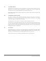
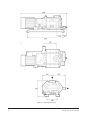
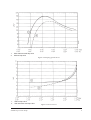
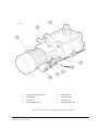
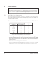
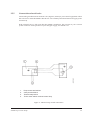
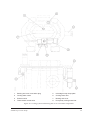
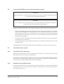
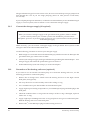
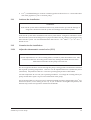
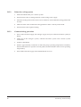
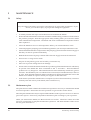
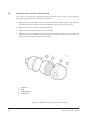
A500-03-880
Issue D
Instruction Manual
DP180 Dry Vacuum Pump
Description
Item Number
DP180 pump, 200 V, 3-phase, 50 Hz
DP180 pump, 200 V, 3-phase, 60 Hz
DP180 pump, 220-240/380-415 V, 3-phase, 50 Hz
DP180 pump, 208-230/380/460 V, 3-phase, 60 Hz
A403-02-934
A403-12-934
A403-02-935
A403-12-995
Manor Royal, Crawley, West Sussex, RH10 9LW, UK
Telephone: +44 (0) 1293 528844 Fax: +44 (0) 1293 533453
http://www.bocedwards.com
CONTENTS
Section
Title
Page
1
1.1
1.2
1.3
1.4
1.5
INTRODUCTION
Scope and definitions
The DP180 pump
Gas-ballast boost
Temperature control system
Accessories
1
1
1
2
2
2
2
2.1
2.2
2.3
2.4
2.5
2.7
TECHNICAL DATA
General
Performance data
Service
Temperature control system
Lubrication system
Noise data
3
3
3
6
6
6
6
3
3.1
3.2
3.3
3.4
3.5
3.5.1
3.5.2
3.5.3
3.5.4
3.5.5
3.6
3.6.1
3.6.2
3.7
3.8
3.9
3.9.1
3.9.2
3.9.3
3.10
3.11
3.12
3.12.1
3.12.2
3.12.3
INSTALLATION
Safety
Unpack and inspect
Fill the pump with oil
Locate the pump
Electrical installation
Select high or low voltage operation
Connect the pump-motor electrical supply
Check the direction of pump rotation
Connect the thermal snap-switch
Connect the solenoid-valve
Connect the cooling-water supply
Supply quality requirements
Connect the supply to the DP180
Connect the DP180 to your vacuum system
Connect the DP180 to your exhaust-extraction system
Gas-ballast boost system
Gas-ballast boost not in use
Standard air gas-ballast boost
Connect the nitrogen supply (if required)
Evacuation of the bearing end-cover (optional)
Leak-test the installation
Commission the installation
Adjust the thermostatic control-valve (TCV)
Prime the cooling system
Commissioning procedure
Ipsitech 8091-03
7
7
7
8
8
10
10
12
12
12
13
14
14
14
16
17
17
17
17
18
18
19
19
19
20
20
DP180 Dry Vacuum Pump
i
Section
4
4.1
Title
Page
OPERATION
Start-up
21
4.2
21
Shut-down
21
5
5.1
5.2
5.3
5.4
5.5
5.6
5.7
5.8
5.9
5.10
MAINTENANCE
Safety
Maintenance plan
Check the gearbox oil-level
Inspect the pipelines and connections
Change the gearbox oil
Relubricate the rotor bearings
Change the head-plate felt filter
Change the gas-ballast air filter element
Clean the inlet-stage sump
Clean the cooling-jacket
22
22
22
23
23
24
24
25
26
27
27
6
6.1
6.2
STORAGE AND DISPOSAL
Storage
Disposal
28
28
28
7
7.1
7.2
7.3
7.4
SERVICE, SPARES AND ACCESSORIES
Introduction
Service
Spares
Accessories
29
29
29
29
30
RETURN OF BOC EDWARDS EQUIPMENT
Illustrations
Figure
1
2
3
4
5
6
7
8
9
10
11
12
ii
Title
Page
Dimensions (mm)
Pumping speed curves
Power curves
Lubrication and gas-ballast boost components
Motor low voltage configuration (200 V, 50/60 Hz; 220-240 V, 50 Hz)
Motor high voltage configuration (380/415 V, 50 Hz; 380 V, 60 Hz)
Motor low voltage configuration (208-230 V, 60 Hz)
Motor high voltage configuration (460 V, 60 Hz)
Thermal snap-switch connections
Cooling system and bearing end-cover evacuation components
Rotor bearing re-lubrication
Exploded view of the gas-ballast air filter
4
5
5
9
11
11
11
11
13
15
25
26
DP180 Dry Vacuum Pump
Tables
Table
1
2
3
4
Title
Full load current ratings
Checklist of components
Pump-motor terminal-box wiring configurations
Maintenance plan
Page
3
8
10
23
Associated publications
Publication title
Vacuum pump and vacuum system safety
DP180 Dry Vacuum Pump
Publication Number
P300-20-000
iii
(This page deliberately left blank)
iv
DP180 Dry Vacuum Pump
1
INTRODUCTION
1.1
Scope and definitions
This manual provides installation, operation and maintenance instructions for the BOC
Edwards DP180 Dry Vacuum Pump (abbreviated to DP180 in the remainder of this manual).
You must use the DP180 as specified in this manual.
Read this manual before you install and operate your DP180. Important safety information is
highlighted as WARNING and CAUTION instructions; you must obey these instructions. The
use of WARNINGS and CAUTIONS is defined below.
WARNING
Warnings are given where failure to observe the instruction could result in injury or death
to people.
CAUTION
Cautions are given where failure to observe the instruction could result in damage to the
equipment, associated equipment or process.
The units used throughout this manual conform to the SI international system of units of
measurement.
1.2
The DP180 pump
The DP180 dry pump operates at pressures between atmospheric and ultimate vacuum without
any lubricating or sealing fluid in the pumping chamber. This ensures a clean pumping system
without back-migration of oil into the system being evacuated. The pump is mounted on steel
runners.
The DP180 is a three-stage, positive-displacement rotary pump in which pairs of intermeshing
rotors (of different profiles mounted on common shafts) are held in correct phase relation by a
pair of timing-gears. The timing-gears and the adjacent double-row angular contact
ball-bearings are oil lubricated.
The pump casing material is cast-iron, the shafts and rotors are made from SG iron. The internal
and external shaft-seals on the pump shafts and the motor drive-shaft are made from
polytetrafluoroethylene (PTFE).
Bearings are located on the high vacuum end of the shaft, near to the pump-inlet. These bearings
are packed with perfluoropolyether (PFPE) grease. As supplied, the bearing end-cover is
connected internally to the pump-inlet and is evacuated when the DP180 pump is operating. If
required, you can use your own external evacuation pump to evacuate the bearing end-cover.
DP180 Dry Vacuum Pump
1
1.3
Gas-ballast boost
The DP180 has a gas-ballast boost system which delivers air to the pump gas-ballast boost inlet.
The flow of air is filtered and is controlled by a solenoid-valve. You can connect the
solenoid-valve to your control equipment to operate the solenoid-valve.
If you wish, you can connect a nitrogen supply to the system in order to deliver nitrogen to the
pump instead of air.
1.4
Temperature control system
The pump is cooled by water which flows through an integral cooling-jacket. The pump is
maintained at a constant operating temperature by a thermostatic control-valve (TCV) which
controls the supply of cooling-water to the pump.
The pump-motor is air-cooled by a cooling-fan which is integral to the motor.
A thermal snap-switch is fitted to the pump-body. This switch shuts down the pump if the pump
is too hot. The switch (which is normally-closed) is connected to the overload control loop of the
pump-motor starter. When the temperature of the pump-body rises to 71 oC, the switch opens
and the pump-motor is switched off.
1.5
Accessories
If the DP180 pump is to be used on clean applications, the pump-outlet can be fitted with a
stainless steel flap-valve accessory. On dirty applications, if the use of an outlet-valve is
necessary, we recommend that you fit a fluoroelastomer flap-valve accessory.
A full list of the accessories available for the DP180 pump is given in Section 7.
2
DP180 Dry Vacuum Pump
2
TECHNICAL DATA
2.1
General
Overall dimensions
Mass
Nominal motor rating
Rotational speed
Warm-up time
Vacuum connections
Inlet
Outlet
Vacuum system maximum leak-rate
Ambient operating temperature range
Maximum ambient operating humidity
Maximum exhaust pressure
2.2
See Figure 1
230 kg
7.5 kW
2000 r min-1
15 min
ISO63
NW40
1 x 10⁻³ mbar l s-1, 1 x 10⁻¹ Pa l s-1
5 to 40 oC
90% RH
2 psig, 1150 mbar absolute,
1.15 x 10⁵ Pa
Performance data
Pumping speed range
Power curves
Peak pumping speed
Displacement (swept volume)
Ultimate vacuum (without outlet flap-valve)
without gas-ballast boost
with full gas-ballast boost
Water vapour pumping speed at 80 mbar (8 x 10³ Pa)
Full load current ratings
Electrical supply
See Figure 2
See Figure 3
180 m3 h-1
200 m3 h-1
1 x 10⁻¹ mbar, 10 Pa
2.5 x 10⁻¹ mbar, 25 Pa
5 kg h-1
See Table 1
Rating (kW)
Full load (A)
50/60
7.5
31.0
208
60
7.0
25.2
220-240
50
7.5
26.8
380-415
50
7.5
15.5
230
60
8.5
25.4
380
60
7.5
19.5
460
60
8.5
14.2
Voltage (V)
Frequency (Hz)
200
Table 1 - Full load current ratings
DP180 Dry Vacuum Pump
3
Figure 1 - Dimensions (mm)
4
DP180 Dry Vacuum Pump
1.
2.
With stainless steel flap-valve
Without flap-valve
Figure 2- Pumping speed curves
1.
2.
Without flap-valve
With stainless steel flap-valve
Figure 3- Power curves
DP180 Dry Vacuum Pump
5
2.3
Services
Electrical supply
Number of phases
Supply voltage
Voltage tolerance
Cooling-water supply
Ryznar Stability Index (RSI)
Water consumption at 20 oC (TCV setting: 3 to 3.5)
Maximum supply pressure
Minimum required pressure differential
across supply and return
Nitrogen supply (if fitted)
Supply pressure
Maximum flow rate
2.4
30 psi
5 to 10 psig
100 l min-1
Danfoss AVTA
130 oC
90 oC
Microtherm
71 ± 3 oC
240 V/2.9 A
Lubrication system
Note:
BOC Edwards Material Safety Data Sheets for the oils and greases referenced below are available
on request.
Gearbox
Fluid capacity (timing gearbox)
Grade of oil
ISO viscosity grade
Recommended perfluoropolyether oils
High vacuum bearings
Grease type
Recommended grease
2.6
6.5 to 7.0
100 l h-1
100 psi
Temperature control system
Thermostatic control-valve
Type
Maximum operating temperature
Maximum sensor temperature
Thermal snap-switch
Manufacturer
Opening temperature
Contact rating
Maximum voltage/current
2.5
3
200/220-240/380-415 V at 50 Hz,
200/208-230/380/460 V at 60 Hz
±6% except for 200 V at 50/60 Hz
and 380 V at 60 Hz which are ±10%
1.2 litres
SAE 40
150
Fomblin Y25 or Krytox 1525
Perfluoropolyether
Fomblin RT15, Krytox 240AD
Noise data
If the DP180 is not fitted inside an acoustic enclosure, under certain pumping conditions the
continuous A-weighted sound pressure level can reach 90 dB(A).
6
DP180 Dry Vacuum Pump
3
INSTALLATION
3.1
Safety
WARNING
Obey the safety instructions given below and take note of appropriate precautions. If you
do not, you can cause injury to people and damage to equipment.
3.2
•
A suitably trained and supervised technician must install the DP180.
•
Ensure that the installation technician is familiar with the safety precautions which relate to
the products pumped. Wear the appropriate safety-clothing when you come into contact
with contaminated components. Dismantle and clean contaminated components inside a
fume-cupboard.
•
If the DP180 is to replace an existing pump, vent and purge the pumping system before you
start any installation work.
•
Disconnect the other components in the pumping system from the electrical supply so that
they cannot be operated accidentally.
•
Do not re-use 'O' rings and Co-Seals and do not allow debris to get into the DP180 during
installation.
•
Before you use the DP180 to pump dangerous substances, refer to the associated publication
referred to at the end of the contents list. You must take all necessary precautions to dilute
flammable gases with nitrogen to a safe level.
•
Leak-test the system after installation and seal any leaks found.
Unpack and inspect
WARNING
Use suitable lifting equipment to move the DP180. Refer to Section 2 for the mass of the
pump.
Use the following procedure to unpack and inspect the pump:
1.
Use a fork-lift truck or a pallet truck to move the DP180 on the pallet into a convenient
position .
2.
Open the cardboard box and remove the packing material from around the pump.
3.
Use suitable lifting-gear attached to the lifting-eyes provided to remove the pump from its
pallet.
DP180 Dry Vacuum Pump
7
4.
Inspect the pump. If the pump or any other item is damaged, notify your supplier and the
carrier in writing within three days; state the Item Number of the pump together with your
order number and your suppliers invoice number. Retain all packing materials for
inspection. Do not use the pump if it is damaged.
5.
Check that the pallet contains the items listed in Table 2. If any of these items is missing,
notify your supplier in writing within three days.
6.
If the pump is not to be used immediately, replace the packing materials and store the pump
in suitable conditions as described in Section 6.
Qty
Description
Check (✓)
1
DP180 pump
❏
1
General fitting-kit
❏
Table 2 - Checklist of components
3.3
Fill the pump with oil
Use the following procedure to fill the pump with oil.
3.4
1.
Refer to Figure 4. Ensure that the oil drain-plug (5) is tight.
2.
Unscrew and remove the oil filler-plug (2).
3.
Fill the gearbox with oil until the oil-level is at the MAX level mark on the oil-level sight-glass
(4).
4.
Check that the rubber bonded seal on the oil filler-plug is in place, then refit the oil filler-plug
(2) and tighten to finger tight. Use a spanner to tighten the plug an additional 1/16 th of a
turn.
Locate the pump
WARNING
Use suitable lifting equipment to move the DP180. Refer to Section 2 for the mass of the
pump.
Use the following procedure to locate the DP180; the DP180 must be located on a firm, level
surface.
8
1.
Use suitable lifting-gear attached to the lifting bolts (see Figure 1) to locate the DP180 in its
final operating position.
2.
If required, fit four bolts through the 12 mm fixing-holes in the runners to secure the DP180
in place. If you do not fit bolts and leave the pump free-standing, we recommend that you fit
vibration isolators; these are available as optional accessories (see Section 7).
DP180 Dry Vacuum Pump
1.
2.
3.
4.
Pump-motor terminal-box
Oil filler-plug
Inlet-flange
Oil-level sight-glass
5.
6.
7.
8.
Oil drain-plug
Solenoid-valve
Clamping-ring
Gas-ballast air filter
Figure 4 - Lubrication and gas-ballast boost components
DP180 Dry Vacuum Pump
9
3.5
Electrical installation
WARNING
Ensure that the electrical installation of the DP180 conforms with your local and national
safety requirements. It must be connected to a suitably fused and protected electrical
supply and a suitable earth (ground) point.
3.5.1
Select high or low voltage operation
The universal voltage and frequency motor can be configured for low voltage operation
(200/220-240 V at 50 Hz or 208-230 V at 60 Hz) or for high voltage operation (415 V at 50 Hz, 380 V
at 50/60 Hz, or 460 V at 60 Hz).
Figures 5 to 8 show the required wiring configurations for the electrical supply voltages and
frequencies as shown in Table 3.
Electrical supply
Voltage (V)
Frequency (Hz)
Refer to
Figure
200
50
5
200
60
5
220-240
50
5
380/415
50
6
208-230
60
7
380
60
6
460
60
8
Table 3 - Pump-motor terminal-box wiring configurations
Use the following procedure to configure the pump for use with your electrical supply:
10
1.
Check the information on the pump-motor data plate to make sure that the pump is suitable
for use with your electrical supply voltage and frequency. If the pump is not suitable, do not
continue to install it.
2.
Remove the cover from the pump-motor terminal-box.
3.
Check the configuration of the links in the motor terminal-box. If necessary, change the
configuration to suit your electrical supply voltage and frequency (see Figures 5 to 8).
DP180 Dry Vacuum Pump
1.
2.
Links
Electrical supply
1.
2.
Figure 5 - Motor low voltage configuration
(200 V, 50/60 Hz; 220-240 V, 50 Hz)
1.
Electrical supply
Figure 7 - Motor low voltage configuration
(208-230 V, 60 Hz)
DP180 Dry Vacuum Pump
Links
Electrical supply
Figure 6 - Motor high voltage configuration
(380/415 V, 50 Hz; 380 V, 60 Hz)
1.
Electrical supply
Figure 8 - Motor high voltage configuration
(460 V, 60 Hz)
11
3.5.2
Connect the pump-motor electrical supply
Notes: Wiring instructions for the pump-motor are also shown on a label inside the terminal-box cover.
The following procedure will ensure that the pump will rotate in the correct direction if phase 1 of
your electrical supply corresponds to line L1 in Figures 5 to 8, phase 2 corresponds to line L2 and
phase 3 corresponds to line L3. However, we recommend that you check the direction of rotation of
the pump as described in Section 3.5.3. You must use the procedure in Section 3.5.3 to check the
direction of rotation if you do not know the phase order of your electrical supply.
Use the following procedure to connect the electrical supply to the pump motor. Connect your
electrical supply to the pump-motor through a suitable contactor which has an overload
protection facility. Use appropriately rated 4-core cable and a suitable cable-gland.
3.5.3
3.5.4
1.
Connect the phase-wires of your electrical supply cable to the appropriate terminals inside
the terminal-box (refer to Section 3.5.1 and to Figures 5 to 8).
2.
Connect the earth (ground) wire to the earth (ground) terminal inside the terminal-box.
3.
Refit the cover to the pump-motor terminal-box.
Check the direction of pump rotation
1.
Look at the pump-motor cooling-fan, switch on the DP180 for one or two seconds, then
switch the DP180 off again.
2.
If the fan rotated anticlockwise when viewed from the motor end of the pump, the direction
of rotation is incorrect. If the direction of rotation is incorrect:
•
Isolate the DP180 from the electrical supply.
•
Remove the cover from the pump-motor terminal-box, reverse any two of the
phase-wires in the terminal-box, then refit the cover to the terminal-box.
•
Repeat the check from Step 1 to ensure that the direction of rotation is correct.
Connect the thermal snap-switch
The thermal snap-switch is fitted to the pump cooling-water jacket and is connected to the 2-way
terminal-block in the motor terminal-box.
You must use a suitable cable to connect the 2-way terminal-block to the motor-starter
overload-control loop, as shown in Figure 9.
You must connect the thermal snap-switch to the motor-starter overload-control loop so that, if
the DP180 overheats and the switch operates (that is, the switch contacts open), it will trip the
contactor and the DP180 will be switched off. When the pump cools and the switch contacts close
again, the DP180 will not then automatically restart; you must manually reset the contactor
before you can start the DP180 again.
12
DP180 Dry Vacuum Pump
3.5.5
Connect the solenoid-valve
Connect the gas-ballast boost solenoid-valve (Figure 4, item 6) to your control equipment so that
the valve closes when the DP180 is shut down. Use a suitably rated fused electrical supply (refer
to Section 2).
If the solenoid-valve is left open after the DP180 is shutdown, the pressure in your vacuum
system could rise to the pressure of your nitrogen supply; see Section 3.9.3.
1.
2.
3.
4.
Pump-motor terminal-box
2-way terminal-block
Thermal snap-switch
To the motor starter overload-control loop
Figure 9 - Thermal snap-switch connections
DP180 Dry Vacuum Pump
13
3.6
Connect the cooling-water supply
CAUTION
If your pump is installed in an area where the ambient temperature falls close to or below
freezing point, ensure that the cooling-water cannot freeze inside the pump cooling-jacket
or TCV. If the cooling-water freezes, the pump or TCV can be damaged.
3.6.1
Supply quality requirements
Your cooling-water must meet the requirements of Section 2.3. If it does not, you may get a
build-up of deposits inside the pump cooling-jacket. If you have any doubt about the quality of
your supply, contact your local water authority who can tell you its RSI and advise on treatments
which you can carry out to make your supply suitable for use with the DP180.
If you use a treated closed-circuit cooling system, we recommend that you fill it (and refill it) with
de-ionised or reverse-osmosis treated water.
3.6.2
Connect the supply to the DP180
CAUTION
Make sure you connect the cooling-water supply and return hoses to the correct
connectors on the DP180. If the hoses are incorrectly fitted, the DP180 may overheat and
may be damaged.
The cooling-water connections on the DP180 are suitable for use with hoses with an outside
diameter of 12 mm (1/2 inch). If you need to connect more than one DP180 to the cooling-water
supply, you must connect the pumps in parallel and not in series.
14
1.
Connect the cooling-water supply hose to the cooling-water inlet (Figure 10, item 6).
2.
Connect the return hose to the pump cooling-water outlet (Figure 10, item 2).
DP180 Dry Vacuum Pump
1.
2.
3.
4.
Bearing end-cover evacuation plug
Cooling-water outlet
Exhaust outlet
Thermostatic control-valve
5.
6.
7.
8.
Inlet-stage sump clamp-plate
Cooling-water inlet
Bearing end-cover
Pump body cooling-water inlet
Figure 10 - Cooling system and bearing end-cover evacuation components
DP180 Dry Vacuum Pump
15
3.7
Connect the DP180 to your vacuum system
WARNING
Do not operate the DP180 with the exhaust-pipeline blocked. If the exhaust-pipeline is
blocked, the DP180 can generate exhaust-pipeline pressures up to 7 bar.
When you connect the DP180 to your vacuum system, take note of the following:
•
To get the best pumping speed, ensure that the pipeline which connects the vacuum system
to the DP180 inlet is as short as possible and has an internal diameter not less than that of the
DP180 inlet port.
•
Incorporate a flexible connection in the pipeline to reduce vibration and stress in the system
pipelines.
•
On very dusty applications, use an inlet-filter to minimise damage to the DP180.
•
You must be able to isolate the pump-inlet from the atmosphere and from your vacuum
system if you have pumped or produced corrosive chemicals.
•
Adequately support vacuum pipelines to stop the transmission of stress to the
coupling-joints.
Use the following procedure to connect the DP180 inlet-flange to your vacuum system.
16
1.
Remove the four cap-head bolts, nuts and washers, then remove the blanking-plate from the
pump-inlet.
2.
Retain the nuts, bolts and washers for future use.
3.
Use the Co-Seal supplied in the fitting-kit to connect the pump inlet-flange to your vacuum
system. Use the bolts provided in the general fitting-kit or the bolts removed in Step 1 to
secure the connection.
DP180 Dry Vacuum Pump
3.8
Connect the DP180 to your exhaust-extraction system
WARNING
Pipe the exhaust to a suitable treatment plant to prevent the discharge of dangerous gases
or vapours to the surrounding atmosphere.
WARNING
Use a catchpot to prevent the drainage of condensate back into the DP180. Condensate
which drains back into the DP180 could damage it.
When you connect the DP180 to your exhaust-extraction system, take note of the following:
•
Incorporate flexible pipelines in the exhaust pipeline to reduce the transmission of vibration
and to prevent loading of the coupling-joints. If you use flexible pipelines, you must use
flexible pipelines which have a maximum pressure rating which is greater than the highest
pressure that can be generated in your system. We recommend that you use BOC Edwards
braided flexible pipelines.
•
You must be able to isolate the pump exhaust from the atmosphere if you have pumped or
produced corrosive chemicals.
•
You must adequately support exhaust pipelines to prevent the transmission of stress to the
coupling-joints.
Use NW40 fittings to connect the outlet-flange of the DP180 to your exhaust-extraction system.
3.9
Gas-ballast boost system
3.9.1
Gas-ballast boost not in use
When the gas-ballast boost is not in use (that is, the solenoid-valve is closed), some process gas
may leak in the reverse direction to atmosphere.
We therefore recommend that you either remove the air-filter and fit an NW10 blanking-plate or
use a positive-pressure nitrogen supply when you pump toxic, pyrophoric or flammable gases,
in order to prevent the leakage of gases into the atmosphere.
3.9.2
Standard air gas-ballast boost
As supplied, the DP180 has a gas-ballast boost system which delivers air to the gas-ballast boost
inlet of the pump. To use this system, connect the solenoid-valve to the electrical supply as
described in Section 3.5.5.
DP180 Dry Vacuum Pump
17
The gas-ballast boost pipe has a non-return valve, however some of the process gas pumped can
leak through the valve if you are rough pumping (above an inlet pressure of 650 mbar,
6.5 x 10⁴ Pa).
If you will pump dangerous substances, we therefore recommend that you use a bottled nitrogen
supply or a closed system; refer to Section 3.9.3 to connect the nitrogen supply.
3.9.3
Connect the nitrogen supply (if required)
WARNING
When you connect a nitrogen supply to the gas-ballast boost pipeline, install a suitable
pressure relief system if your vacuum system is not suitable for pressures above
atmospheric pressure. If you do not, the pressure in your system could rise to the pressure
of the nitrogen supply.
When necessary, you can connect a nitrogen supply to the gas-ballast boost system so that
nitrogen is delivered to the DP180 instead of air.
Use the following procedure to connect your nitrogen supply.
3.10
1.
Refer to Figure 3. Undo and remove the NW10 clamp (7) which secures the air-filter (8) to the
gas-ballast boost pipe. Remove the air-filter.
2.
Connect your nitrogen supply to the gas-ballast boost pipe through an NW10 adaptor. Your
nitrogen supply must meet the specification given in Section 2.
3.
Fit the NW10 clamp (removed in Step 1) to secure the adaptor.
Evacuation of the bearing end-cover (optional)
If you want to use an external evacuation pump to evacuate the bearing end-cover, use the
following procedure to connect the pump:
18
1.
Remove the six fixing-screws which secure the bearing end-cover to the high vacuum
head-plate (see Figure 10).
2.
Lift away the end-cover and carefully remove the sealing 'O' ring.
3.
Use a suitable tool to prise the felt filter out from the head-plate.
4.
Apply a light wipe of sealing compound to a 1/4 inch BSP tapered plug and fit the plug to the
head-plate.
5.
Check the condition of the 'O' ring removed in Step 2. If the 'O' ring is damaged, replace it
with a new 'O' ring.
6.
Apply a light wipe of PFPE grease to the 'O' ring and place it in its groove on the head-plate.
Refit the bearing end-cover to the head-plate.
7.
Remove the 3/8 inch BSP taper-plug from the bearing end-cover.
DP180 Dry Vacuum Pump
8.
3.11
Use 3/8 inch BSP fittings to connect a suitable pipeline to the end-cover. Connect the other
end of the pipeline to your evacuation pump.
Leak-test the installation
WARNING
Leak-test the system after installation and seal any leaks found to prevent the leakage of
dangerous substances from the system and leakage of air into the system.
Leak-test the system after installation and seal any leaks found. Dangerous substances which
leak from the system will be dangerous to people and there may be a danger of explosion if air
leaks into the system. We recommend that the leak rate is 1 x 10⁻³ mbar l s-1 (1 x 10⁻¹ Pa l s-1)
helium or less.
3.12
Commission the installation
3.12.1
Adjust the thermostatic control-valve (TCV)
CAUTION
Do not adjust the TCV to a lower setting (that is, towards 0) when the DP180 is hot. This
will increase the flow of cooling-water which may damage the DP180 because of the
differential contraction of the pump rotor and case.
The TCV regulates the flow of water through the pump cooling-jacket to maintain the DP180 at
the required operating temperature. The TCV can be adjusted between 0 (minimum) and 5
(maximum). Adjustment of the TCV varies the operating temperature of the DP180.
You must adjust the TCV to suit your operating conditions. Use a high TCV setting when you
pump condensable vapours to prevent condensation in the pump.
We recommend that you do not exceed a maximum DP180 operating temperature of 65 oC in
normal use (that is, a TCV setting of 3 to 3.5). If you set the TCV at a higher temperature, the
thermal snap-switch will operate to shut down the DP180.
DP180 Dry Vacuum Pump
19
3.12.2
3.12.3
20
Prime the cooling system
1.
Isolate the DP180 from your vacuum system.
2.
Turn the TCV to the '0' setting and turn on the cooling-water supply.
3.
Allow the cooling-water to flow for five to six minutes to ensure that the cooling-jacket is full
of water.
4.
Check all of the water connections and pipelines for leaks. Seal any leaks found.
5.
Turn the TCV to the required setting.
Commissioning procedure
1.
Turn on the electrical supply, the nitrogen supply and your exhaust-extraction system (if
fitted).
2.
Check all of the nitrogen system, exhaust-extraction system and vacuum system
connections.
3.
Switch on the DP180.
4.
Wait for approximately 15 minutes to allow the pump operating temperature to stabilise,
then check that the TCV operates correctly (that is, that the DP180 is at the correct operating
temperature).
5.
Turn off the electrical supply to the DP180 and the services.
DP180 Dry Vacuum Pump
4
OPERATION
WARNING
Take all appropriate safety precautions when you pump oxidants or pyrophoric or
flammable gases.
4.1
Start-up
Use the following procedure below to start up the pump.
4.2
1.
Check the gearbox oil-level in the sight-glass on the side of the pump (Figure 4, item 4). The
oil-level must be between the MIN and MAX marks when the pump is cold and at rest. If
necessary, pour more oil into the pump (refer to Section 3.3) or drain oil from the pump (refer
to Section 5.5).
2.
Switch on the electrical supply, the cooling-water supply, the nitrogen supply and the
exhaust-extraction system (if fitted).
3.
Check all of the water, nitrogen system, exhaust-extraction system (if any) and vacuum
system connections.
4.
Switch on the DP180.
5.
If required, use your control equipment to open the gas-ballast boost solenoid-valve. Set
your nitrogen supply pressure and flows to suit your process conditions.
Shut-down
Use the following procedure to shut down the DP180.
1.
Isolate the pump-inlet from your vacuum system and operate the DP180 for 15 minutes with
the gas-ballast boost solenoid-valve open.
2.
Close the gas-ballast boost solenoid-valve and switch off your nitrogen supply (if fitted).
3.
Switch off the DP180.
4.
Turn off the cooling-water supply and your exhaust-extraction system (if fitted).
DP180 Dry Vacuum Pump
21
5
MAINTENANCE
5.1
Safety
WARNING
Obey the safety instructions given below and take note of appropriate precautions. If you
do not, you can cause injury to people and damage to equipment.
5.2
•
A suitably trained and supervised technician must maintain the DP180.
•
Ensure that the maintenance technician is familiar with the safety procedures which relate to
the products pumped. Wear the appropriate safety-clothing when you come into contact
with contaminated components. Dismantle and clean contaminated components inside a
fume-cupboard.
•
Allow the DP180 to cool to a safe temperature before you start maintenance work.
•
Vent and purge the pumping system with nitrogen before you start any maintenance work.
•
Isolate the DP180 and other components in the pumping system from the electrical supply so
that they can not be operated accidentally.
•
Recheck the direction of pump rotation if the electrical supply has been disconnected.
•
Do not reuse 'O' rings and Co-Seals.
•
Dispose of components, grease and oil safely (see Section 6.2).
•
Take care to protect sealing-faces from damage.
•
Do not touch or inhale the thermal breakdown products of fluorinated materials which may
be present if the DP180 has been overheated to 260 oC and above. These breakdown
products are very dangerous. Fluorinated materials in the DP180 may include oils, greases
and seals. The DP180 may have overheated if it was misused, if it malfunctioned, or if it was
in a fire. BOC Edwards Materials Safety Data Sheets for fluorinated materials used in the
DP180 are available on request: contact your supplier or BOC Edwards.
•
Leak-test the system after maintenance is complete if you have disconnected any vacuum or
exhaust joints and seal any leaks found (refer to Section 3.11).
Maintenance plan
The plan shown in Table 4 details the maintenance operations necessary to maintain the DP180
in normal operation. Instructions for each operation are given in the section shown.
More frequent maintenance may be required if the DP180 is used to process corrosive or abrasive
gases and vapours. If necessary, adjust the maintenance plan according to your experience.
When you maintain the DP180, use BOC Edwards service kits. These kits contain all of the
necessary components to complete maintenance operations. The Item Numbers of the service
kits are given in Section 7.3.
22
DP180 Dry Vacuum Pump
Operation
Frequency
Refer to Section
Monthly
5.3
Inspect the pipelines and connections
6 Monthly
5.4
Change the gearbox oil
6 Monthly
5.5
Relubricate the rotor bearings
6 Monthly
5.6
Change the head-plate felt filter
Yearly
5.7
Change the gas-ballast air filter element
Yearly
5.8
Clean the inlet-stage sump
As required
5.9
Clean the cooling-jacket
As required
5.10
Check the gearbox oil-level
Table 4 - Maintenance plan
5.3
Check the gearbox oil-level
Refer to Figure 4. Check the pump gearbox oil-level on the sight-glass (4). The level of oil must be
between the MIN and MAX marks when the pump is off and is cold:
5.4
•
If the oil-level is below the MIN mark, pour more oil into the DP180 until the oil-level is
correct: refer to Section 3.3.
•
If the oil-level is above the MAX mark, drain oil from the gearbox until the oil-level is correct:
refer to Section 5.5.
Inspect the pipelines and connections
1.
Inspect all of the cooling-water connections and check that they are secure; tighten any loose
connections. Inspect all of the cooling-water pipelines and connections and check for leaks;
seal any leaks found. Inspect all of the cooling-water pipelines and connections and check
for corrosion and damage; repair or replace any corroded or damaged component.
2.
Inspect all of the gas-ballast boost connections and check that they are secure; tighten any
loose connections. Inspect all of the gas-ballast boost pipelines and connections and check
for leaks; seal any leaks found. Inspect all of the gas-ballast boost pipelines and connections
and check for corrosion and damage; repair or replace any corroded or damaged
component.
3.
Inspect all of the electrical connections and check that they are secure; tighten any loose
connections. Inspect all of the electrical cables and check that they are not damaged and have
not overheated; replace any damaged or overheated cable.
4.
Inspect all of the vacuum connections and check that they are secure; tighten any loose
connection. Inspect all of the vacuum pipelines and connections for corrosion and damage;
replace any corroded or damaged components.
DP180 Dry Vacuum Pump
23
5.5
5.6
Change the gearbox oil
1.
Refer to Figure 4. Remove the oil filler-plug (4).
2.
Place a suitable container under the oil drain-plug (5).
3.
Remove the oil drain-plug (5) and allow the oil to drain out of the gearbox.
4.
Refit the oil drain-plug (5).
5.
Dispose of the old rubber bonded seal on the oil filler-plug (4) and replace it with a new one
from the pump maintenance kit.
6.
Fill the gearbox through the filler-hole, with the correct grade and quantity of oil. Allow the
oil to drain into the gearbox and then check the level on the oil-level sight-glass: refer to
Section 5.3.
7.
Ensure that the new rubber bonded seal is positioned correctly on the oil filler-plug (4), then
refit the plug to the gearbox.
Relubricate the rotor bearings
Relubricate the rotor bearings as described below.
24
1.
Refer to Figure 11. Remove the six fixing-screws (2) which secure the bearing end-cover (1)
to the high vacuum head-plate.
2.
Lift away the end-cover (1) and remove the sealing 'O' ring (3). Dispose of the 'O' ring (see
Section 6.2).
3.
Use a plastic or wooden spatula to remove as much old grease as possible from the end-cover
and bearings (5). Do not use your fingers for this operation.
4.
Inspect the bearings for obvious signs of wear or the presence of debris. If the bearings are
worn, return the pump to a BOC Edwards Service Centre for repair.
5.
If the bearings are in a satisfactory condition, force new PFPE grease (supplied in the
maintenance kit) into the bearings so that a smooth layer of grease covers the case and
bearings. Do not over-pack the bearings or the DP180 will run hot.
6.
If you have not fitted a pump to evacuate the bearing end-cover (see Section 3.10) and you
have reached the planned time to replace the head-plate felt filter (this is carried out
annually), replace the filter as described in Section 5.7. Otherwise, continue at Step 7 below.
7.
Apply a light wipe of PFPE grease to the new 'O' ring seal (3) and position it in its groove in
the head-plate.
8.
Refit the end-cover (1) to the high vacuum head-plate and secure with the six screws (2).
DP180 Dry Vacuum Pump
1.
2.
3.
Bearing end-cover
Screw
'O' ring
4.
5.
6.
Felt filter
Bearing
End-cover cavity
Figure 11 - Rotor bearing relubrication
5.7
Change the head-plate felt filter
If you have not connected an external pump to evacuate the bearing end-cover (see Section 3.10),
you must change the felt filter in the head-plate annually. As you must remove the bearing
end-cover to replace the felt filter, it is convenient to carry out this maintenance when you
relubricate the rotor bearings (see Section 5.6). Use the following procedure to change the filter;
this procedure assumes that you have already carried out Steps 1 to 5 in Section 5.6.
1.
Refer to Figure 4. Use a suitable tool to prise out the felt filter (4) from the high vacuum
head-plate. Dispose of the filter (see Section 6).
2.
Place the new felt filter (supplied in the maintenance kit) into the head-plate.
3.
Refit the end-cover (1) to the pump as described in Step 7 of Section 5.6.
DP180 Dry Vacuum Pump
25
5.8
Change the gas-ballast air filter element
If you have not connected a nitrogen gas-ballast supply to the pump, use the following
procedure to replace the gas-ballast air filter element:
1.
Refer to Figure 12. Turn the top-cap (1) clockwise (when viewed from the top-cap end of the
gas-ballast air filter) to release it from the filter body (4), then remove the top-cap.
2.
Remove and dispose of the used filter element (3).
3.
Fit the new filter element (3) into the filter body (4).
4.
Refit the top-cap (1) to the filter body (4) and turn it anticlockwise until it clicks, to secure it to
the filter body: ensure that the inlet (2) on the top-cap does not point upwards, otherwise
debris, dust or liquids may enter the filter body.
1.
2.
3.
4.
Top-cap
Inlet
Filter element
Filter body
Figure 12 - Exploded view of the gas-ballast air filter
26
DP180 Dry Vacuum Pump
5.9
Clean the inlet-stage sump
Clean the inlet-stage sump regularly if you use the DP180 to pump dusty or tarry vapours. Use
the following procedure:
5.10
1.
Remove the two screws on the clamp which secures the inlet-stage sump blanking-plate to
the pump (see Figure 10).
2.
Remove the clamp, the blanking-plate and the sealing 'O' ring. Dispose of the 'O' ring.
3.
Use a suitable tool (for example, a flexible handled, large diameter bottle-brush) to clean the
sump. Do not use your fingers for this operation.
4.
Use a suitable cleaning solution to clean the blanking-plate. Make sure that all traces of the
cleaning solution are removed before you refit the plate.
5.
Apply a light wipe of high vacuum grease to the new 'O' ring. Refit the 'O' ring and
blanking-plate to the pump, then use the clamp and the two fixing-screws to secure the
blanking plate in place.
Clean the cooling-jacket
Flush the cooling-jacket to clean it; that is allow water to flow rapidly through the cooling-jacket
in the reverse direction of normal flow. Use the following procedure.
1.
Turn off the cooling-water supply.
2.
Refer to Figure 10. Place a suitable container under the pump-body cooling-water inlet
connection (8) and undo the connection. Allow the water to drain out of the pump.
3.
Disconnect the water return hose from the cooling-water outlet (2).
4.
Connect the cleaning water supply to the pump cooling-water outlet (2).
5.
Place a suitable container under the pump-body cooling-water inlet or connect a return hose
to the pump-body tapping.
6.
Turn on the cleaning water supply. The pressure and flow rate of the supply should be equal
to or higher than the normal cooling-water pressure and flow rate. Do not exceed the figures
stated in Section 2.
7.
Allow the water to flow for a few minutes, then turn off the cleaning water supply.
8.
Disconnect the cleaning water supply hose (and the return hose, if fitted). Allow the water to
drain out of the pump.
9.
Use a suitable tool to probe the pump-body cooling-water outlet and the cooling-water inlet
and remove any remaining sediment.
10. Refit the pump-body cooling-water inlet connection to the pump-body.
11. Connect the normal cooling-water supply and return hoses to the cooling-water inlet and
outlet connections (refer to Section 3.6.2).
12. Prime the pump as described in Section 3.12.2.
DP180 Dry Vacuum Pump
27
6
STORAGE AND DISPOSAL
6.1
Storage
Store the DP180 as follows :
6.2
1.
If applicable, ensure that the DP180 has been shut down as described in Section 4.2 and
disconnect all services, process and exhaust connections.
2.
Drain the water from the cooling-jacket as described in Section 5.10.
3.
Fit blanking-plates to all vacuum inlets and outlets. Place protective covers over the pump
services connection points.
4.
Store the pump in clean dry conditions until required.
5.
When required for use, prepare and install the pump as described in Section 3.
Disposal
Dispose of the DP180, use oil and grease and any components safely in accordance with all local
and national safety and environmental requirements.
Take particular care with the following:
28
•
Fluoroelastomers which may have decomposed as the result of being subjected to high
temperatures.
•
Components which have been contaminated with dangerous process substances.
DP180 Dry Vacuum Pump
7
SERVICE, SPARES AND ACCESSORIES
7.1
Introduction
BOC Edwards products, spares and accessories are available from BOC Edwards companies in
Belgium, Brazil, China, France, Germany, Israel, Italy, Japan, Korea, Singapore, United
Kingdom, U.S.A and a world-wide network of distributors. The majority of these centres
employ Service Engineers who have undergone comprehensive BOC Edwards training courses.
Order spare parts and accessories from your nearest BOC Edwards company or distributor.
When you order, please state for each part required:
7.2
•
Model and Item Number of your equipment.
•
Serial number (if any).
•
Item Number and description of the part.
Service
BOC Edwards products are supported by a world-wide network of BOC Edwards Service
Centres. Each Service Centre offers a wide range of options including: equipment
decontamination; service exchange; repair; rebuild and testing to factory specifications.
Equipment which has been serviced, repaired or rebuilt is returned with a full warranty.
Your local Service Centre can also provide BOC Edwards engineers to support on-site
maintenance, service or repair of your equipment.
For more information about service options, contact your nearest Service Centre or other BOC
Edwards company.
7.3
Spares
The following spares are available for the DP180:
Product
DP180 spares kit
DP180 seals kit
DP180 tools kit
Thermostatic control-valve
Gas-ballast boost solenoid-valve
Krytox 1525 oil (1 kg)
Fomblin RT15 grease (100 g)
DP180 Dry Vacuum Pump
Item Number
A403-02-934
A403-02-820
A403-02-027
A500-64-000
A287-03-012
H113-09-018
H113-50-003
29
7.4
Accessories
The accessories listed below are available for the DP180. Each accessory contains all the
necessary components for assembly and installation of the accessory. Full functional
descriptions and fitting details are included in the instruction manual supplied with the
accessory.
Accessory
Acoustic enclosure with vibration isolators
Vibration isolators (set of 4)
Exhaust-silencer
Exhaust-silencer with enclosure
Gas-ballast boost assembly : manual
Gas-ballast boost assembly : solenoid-valve
Inlet isolation-valve
Inlet dust-filter
Outlet flap-valve pack*
Item Number
A500-65-000
A248-01-414
A500-71-000
A500-83-000
A500-66-000
A500-67-000
B424-03-000
A443-03-000
A500-72-000
*The outlet flap-valve pack contains a stainless steel flap-valve and a fluoroelastomer flap-valve.
30
DP180 Dry Vacuum Pump
Form HS1
Return of BOC Edwards Equipment - Procedure
INTRODUCTION
Before returning your equipment, you must warn BOC Edwards if substances you used (and produced)
in the equipment can be hazardous. This information is fundamental to the safety of our Service Centre
employees and will determine the procedures employed to service your equipment.
Complete the Declaration (HS2) and send it to BOC Edwards before you dispatch the
equipment. It is important to note that this declaration is for BOC Edwards internal use only, and
has no relationship to local, national or international transportation safety or environmental
requirements. As the person offering the equipment for shipment, it is your responsibility to ensure
compliance with applicable laws.
P900-70-000 Issue K
GUIDELINES
• Equipment is 'uncontaminated' if it has not been used, or if it has only been used with substances
that are not hazardous. Your equipment is 'contaminated' if it has been used with any substances
classified as hazardous under EU Directive 67/548/EEC (as amended) or OSHA Occupational Safety
(29 CFR 1910).
• If your equipment has been used with radioactive substances, biological or infectious agents,
mercury, polychlorinated biphenyls (PCB’s), dioxins or sodium azide, you must decontaminate it
before you return it to BOC Edwards. You must send independent proof of decontamination (for
example a certificate of analysis) to BOC Edwards with the Declaration (HS2). Phone BOC
Edwards for advice.
• If your equipment is contaminated, you must either:
• Remove all traces of contamination (to the satisfaction of laws governing the transportation of
dangerous/hazardous substances).
• Or, properly classify the hazard, mark, manifest and ship the equipment in accordance with
applicable laws governing the shipment of hazardous materials.
Note: Some contaminated equipment may not be suitable for airfreight.
PROCEDURE
1. Contact BOC Edwards and obtain a Return Authorisation Number for your equipment.
2. Complete the Return of BOC Edwards Equipment - Declaration (HS2).
3. If the equipment is contaminated, you must contact your transporter to ensure that you properly
classify the hazard, mark, manifest and ship the equipment, in accordance with applicable laws
governing the shipment of contaminated/hazardous materials. As the person offering the equipment
for shipment, it is your responsibility to ensure compliance with applicable law. Note: Equipment
contaminated with some hazardous materials, such as semiconductor by-products,
may not be suitable for airfreight - contact your transporter for advice.
4. Remove all traces of hazardous gases: pass an inert gas through the equipment and any accessories
that will be returned to BOC Edwards. Where possible, drain all fluids and lubricants from the
equipment and its accessories.
5. Seal up all of the equipment's inlets and outlets (including those where accessories were attached)
with blanking flanges or, for uncontaminated product, with heavy gauge tape.
6. Seal equipment in a thick polythene/polyethylene bag or sheet.
7. If the equipment is large, strap the equipment and its accessories to a wooden pallet. If the
equipment is too small to be strapped to a pallet, pack it in a suitable strong box.
8. Fax or post a copy of the Declaration (HS2) to BOC Edwards. The Declaration must arrive before
the equipment.
9. Give a copy of the Declaration (HS2) to the transporter. You must tell your transporter if the
equipment is contaminated.
10. Seal the original Declaration in a suitable envelope: attach the envelope securely to the outside of
the equipment package, in a clear weatherproof bag.
WRITE YOUR RETURN AUTHORISATION NUMBER CLEARLY ON THE
OUTSIDE OF THE ENVELOPE OR ON THE OUTSIDE OF THE EQUIPMENT
PACKAGE.
Form HS2
Return of BOC Edwards Equipment - Declaration
Return Authorisation Number:
You must:
•
Know about all of the substances which have been used and produced in the equipment before you complete this Declaration
•
Read the Return of BOC Edwards Equipment - Procedure (HS1) before you complete this Declaration
•
Contact BOC Edwards to obtain a Return Authorisation Number and to obtain advice if you have any questions
•
Send this form to BOC Edwards before you return your equipment
SECTION 1: EQUIPMENT
Equipment/System Name_________________________
IF APPLICABLE:
Part Number _________________________________
Tool Reference Number_________________
Serial Number_________________________________
Process ______________________________
Has the equipment been used, tested or operated ?
Failure Date___________________________
YES
Serial Number of
Replacement Equipment_________________
R Go to Section 2
NO
R Go to Section 4
SECTION 2: SUBSTANCES IN CONTACT WITH THE EQUIPMENT
Are any substances used or produced in the equipment:
•
•
Radioactive, biological or infectious agents, mercury,
poly chlorinated biphenyls (PCBs), dioxins
or sodium azide? (if YES, see Note 1) YES
NO
R
YES R
Hazardous to human
health and safety?
R
NO R
Note 1 : BOC Edwards will not accept delivery of any
equipment that is contaminated with radioactive substances,
biological/infectious agents, mercury, PCB’s, dioxins or
sodium azide, unless you:
•
•
Decontaminate the equipment
Provide proof of decontamination
YOU MUST CONTACT BOC EDWARDS FOR ADVICE
BEFORE YOU RETURN SUCH EQUIPMENT
SECTION 3: LIST OF SUBSTANCES IN CONTACT WITH THE EQUIPMENT
Chemical
Symbol
Substance name
Precautions required (for example,
use protective gloves, etc.)
Action required after a spill,
leak or exposure
SECTION 4: RETURN INFORMATION
Reason for return and symptoms of malfunction _________________________________________________
_________________________________________________________________________________
If you have a warranty claim:
•
who did you buy the equipment from ? _____________________________
•
give the supplier’s invoice number_________________________________
SECTION 5: DECLARATION
Print your name:_________________________________Print your job title:_________________________
Print your organisation:____________________________________________________________________
Print your address:_______________________________________________________________________
Telephone number: ___________________________Date of equipment delivery: ______________
I have made reasonable enquiry and I have supplied accurate information in this
Declaration. I have not withheld any information, and I have followed the Return of
BOC Edwards Equipment - Procedure (HS1).
Signed: _____________________________________Date______________
Note: Please print out this
form, sign it and return the
signed form as hard copy.
P900-71-000 Issue K
_______________________________________________________________________
This page intentionally blank.
UNITED KINGDOM
CANADA
ISRAEL
CORPORATE HEADQUARTERS
BOC EDWARDS
Manor Royal
Crawley
West Sussex
RH10 9LW
Tel +(44) 1293 528844
Fax +(44) 1293 533453
BOC EDWARDS
5975 Falbourne Street
Mississauga, Ontario L5R3W6
Canada
Tel +(1) 905 501 2558
Fax +(1) 905 501 1632
EDWARDS ISRAEL VACUUM LTD.
5 Habarzel Blvd
Gat 2000 Industrial Zone
Qiryat Gat 82000
Tel +(972) 8 681 0633
Fax +(972) 8 681 0640
12055 Cote de Liesse
Dorval, Quebec H9P1B4
Canada
Tel +(1) 514 631 3501
Fax +(1) 514 631 3502
ITALY
BOC EDWARDS
Wingates Industrial Estate
Great Bank Road
Westhoughton, Bolton
Lancashire
BL5 3SL
Tel +(44) 1942 652652
Fax +(44) 1942 652651
AMERICA (USA)
USA HEADQUARTERS
BOC EDWARDS
One Edwards Park
301 Ballardvale Street
Wilmington, MA 01887
Tel +(1) 978 658 5410
Toll free (USA only) 1 800 848 9800
Fax +(1) 978 658 7969
3901 Burton Drive
Santa Clara, CA 95054
Tel +(1) 408 496 1177
Fax +(1) 408 496 1188
1810 West Drake Drive
Suite 101
Tempe, AZ 85283
Tel +(1) 602 777 7007
Fax +(1) 602 777 2244
P800-80-000 Issue J 01A09-010
11701 Stonehollow Drive
Suite 100
Austin, TX 78758
Tel +(1) 512 491 6622
Fax +(1) 512 491 0629
CHINA
BOC TRADING
(SHANGHAI) CO. LTD.
23 Fu Te Road (N)
Wai Gao Qiao Free Trade Zone
Pudong
Shanghai, 200131
PRC China
Tel +(86 21) 5866 9618
Fax +(86 21) 5866 9993
HEADQUARTERS
BOC EDWARDS
Shuwa Shiba Park Building A-3F
2-4-1 Shibakoen Minato-ku
Tokyo, 105-0011
Tel +(81) (0) 3 5470 6530
Fax +(81) (0) 3 5470 6521
KOREA
BOC EDWARDS
125 Avenue Louis Roche
92238 Gennevilliers, Cedex
Paris
Tel +(33) 1 47 98 24 01
Fax +(33) 1 47 98 44 54
HEADQUARTERS
SONGWON EDWARDS LTD.
5th FL. Daewoo Engineering Bldg.
Soonae-dong
Bundang-gu, Sungnam City
Kyungki-do, Korea
Tel +(82) 31 716 7070
Fax +(82) 31 738 1001-3
GERMANY
BOC EDWARDS
Ammerthalstraße 36
85551 Kirchheim
Munich
Tel +(49) 89 99 19 18 0
Fax +(49) 89 99 19 18 99
HONG KONG S.A.R.
3501 Island Avenue
Philadelphia, PA 19153
Tel +(1) 215 365 8653
Fax +(1) 978 753 6846
BELGIUM
INDIA
BOC EDWARDS
Bergensesteenweg 709
B1600 Sint-Pieters-Leeuw
Brussels
Tel +(32) 2 363 0030
Fax +(32) 2 363 0064
BOC EDWARDS
DIVIN. OF BOC INDIA LIMITED
203 Surya Kiran Building
19 Kasturba Gandhi Marg
New Delhi - 110 001
India
Tel +(91) 11 851 0065
Fax +(91) 11 851 0245
BOC DO BRASIL LTDA
DIVISÃO EDWARDS ALTO VACO
Rua Bernado Wrona 222
02710 São Paulo-SP
Tel +(55) 11 3952 5000
Fax +(55) 11 3965 2766
JAPAN
FRANCE
BOC EDWARDS (ASIA)
12 Chun Yat Street
Tseung Kwan O Industrial Estate
Tseung Kwan O, Kowloon
Hong Kong S.A.R.
Tel +(852) 2372 2640
Fax +(852) 2796 9095
BRAZIL
BOC EDWARDS
Via Carpaccio 35
20090 Trezzano sul Naviglio
Milan
Tel +(39) 02 48 4471
Fax +(39) 02 48 401638
FACTORY & GV
SONGWON EDWARDS LTD.
625-7 Upsong-dong
Chunan City
Chungchong Nam-do
Korea
Tel +(82) 41 621 7070
Fax +(82) 41 621 7700
SINGAPORE
BOC EDWARDS (ASIA)
42 Loyang Drive
Loyang Industrial Estate
Singapore 508962
Tel +(65) 6546 8408
Fax +(65) 6546 8407
TAIWAN, R.O.C.
EDWARDS TECHNOLOGIES
LIMITED
No. 434 Chung hua Road
Toufen Town, Miaoli County
Taiwan ROC
Tel +(886) 37 611422
Fax +(886) 37 611401
PLEASE CONTACT ANY OF THESE COMPANIES FOR DETAILS OF OTHER SALES AND
SERVICE CENTRES IN YOUR AREA.
BOC Edwards is part of BOC Limited. BOC Edwards and the stripe symbol are trade marks of The BOC Group.
© BOC Edwards 2003
Produced by Technical Publicity [email protected]
http://www.bocedwards.com
[email protected]