Transcript
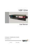
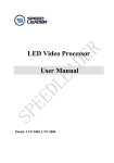
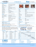
Quick setup sheet for the TL-358/2
Mounting
1
K5940069-00
Connecting the power
The TL-358/2 can be mounted on
a rack with 4 (M6) capitve
hexagon slotted head bolts
(key width 8, screwing torque =
max. 9 Nm)
Connecting the signals
1
3
1
2
3
2
1
2
Screws are not included in the standard Barco offering.
DVI1 input connector
DVI2 input connector
Analog input connector
1
DC power: Connect the power cable to the DC power
connector of the unit and tighten the locking screws.
See user manual for connector pinning or
use the ordered power cord.
,
2
Digital input: Connect (a) digital device(s)
to the DVI connector(s) (DVI1, DVI2).
3
Analog input: Connect an analog device
to the analog input connector.
AC power: Connect the power cable to the Ac power
connector of the unit.
See user manual for connector pinning or use the ordered
power cord.
See user manual for connector pinnings.
Power on the power supply
VESA mounting will limit the environmental performance!
Control panel
Using the OSD
menu structure
Brightness
1
2
To adjust the brightness, push the up or down button. When no
OSD menus are visible, the brightness bar appears on the screen.
1
Press the Select button.
As a result, the OSD main menu comes up:
Brightness can be adjusted from 0 (black screen) to 100.
Input
Input selection
1
2
3
2
Up button
Down button
Select button
1
2
The TL-358/2 has the following
possible IAW VESA standard
mounting solution:
200mm x 100mm (M6),
maximum screwdepth in the
unit is 9mm.
1
2
3
4
4
5
5
Exit button
Standby button
About this display
Status
Enable Service
Mode
2
Use the Up/Down buttons to move to the desired submenu.
3
To go into a submenu use the Select button.
Automatic input selection: the first valid signal detected
by the display will automatically be selected and displayed.
4
Use the Up/Down buttons to change values or make selections.
Manual input selection: manual input selection can be done
via the “Input” menu, accesible via the OSD main menu.
5
To confirm adjustments and selections, use the Select button.