1
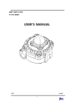
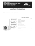
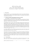
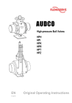
MANUAL
FOR
INSTALLATION
AND
OPERATING
for the gearbox model ILG/S
ILG/S gearbox
1.
1.1
1.2
3.
4.
5.
manual
Preface ......................................................................................................................................................................... 3
Technical data ............................................................................................................................................................ 3
Handling and safety precautions............................................................................................................................. 3
Adjustment of the stopscrews.................................................................................................................................. 6
Operating..................................................................................................................................................................... 7
Maintenance............................................................................................................................................................... 8
2
J+J Deutschland GmbH, Auf der Hackelmasch 1, 31061Alfeld,
fon +4951816017, Fax.+4951816032
mail: [email protected]
homepage: www.juj-deutschland.de
ILG/S gearbox
manual
1. Preface
Rotork Gears bv produces gearboxes of different types and sizes. The ILG/S gearbox of Rotork Gears is a
sandwich manual override quarter turn gearbox for single acting actuators. It is intended to be used for the
manual operation of valves in pipelines, in case of failure of the of the automatic actuator system.
NB. This manual is valid only for the standard ILG/S gearboxes of Rotork Gears bv. For special versions, the
specifications and model can differ.
Rotork Gears bv is not responsible for any damage caused by incorrect use of the gearbox.
1.1
Technical data
Specifications
The maximum allowable input- and outputtorque are listed in table 1.
Gearbox
size
ILG/S 210
ILG/S 550
ILG/S 880
ILG/S 1250
ILG/S 1950
ILG/S 1950 SP4
ILG/S 6800
ILG/S 6800 SP4
ILG/S 250 SP4
connection to
actuator
ISO 5211
F05-F07
F07-F10-F12
F10-F12-F14
F12-F14-F16
F16-F25
F16-F25
F25-F30
F25-F30
F25-F30
connection to
valve
ISO 5211/1
F05-F07-F10
F07-F10-F12-F14
F10-F12-F14-F16
F10-F12-F14-F16
F12-F14-F16-F25
F12-F14-F16-F25
F16-F25-F30
F16-F25-F30
F25-F30-F35-F40
Max. Torque [Nm]
Inputshaft Output
28.5
330
78
934
123
1620
139
2640
160
3050
125
6800
160
4400
134
12500
142
32000
table 1 : Connectiondata of the gearboxes
The Rotork Gears gearboxes can be used at ambient temperatures from –20 to +110°C.
For more specified information, you can contact our sales departement.
1.2
Handling and safety precautions
Be sure to read and understand this manual before installation and use of our ILG/S-gearbox.
Storage
The gearboxes need to be stored in a safe way to avoid accidents. Also avoid storage in areas subjected to high
temperature extremes and /or areas subjected to large amounts of humidity and dust.
Handling
Never drop the gearbox or otherwise subject it to strong impact.
3
J+J Deutschland GmbH, Auf der Hackelmasch 1, 31061Alfeld,
fon +4951816017, Fax.+4951816032
mail: [email protected]
homepage: www.juj-deutschland.de
ILG/S gearbox
manual
Correct use
Prior to installation, be sure the gearbox will NOT be overloaded during normal use. For this, convince yourself
the valvesize and needed opening and closing torque do not exceed the values given for the gearbox. For the
maximum allowable torque of the gearbox, see table 1.
Rotork Gears bv is not responsible for any damage caused by incorrect use of the gearbox.
Installation en operating
Not observing and following the rules as stated in this manual can lead to damage and / or personal injuries. The
qualified personel must be fully aware of the instructions as descibed in this manual.
Only when the instructions are observed, correct operation of the gearboxes can be garanteed.
Disposal
Never refuse a gearbox at a general disposal unit. The gearbox has to be offered to a disposal depot for recycling.
The iron parts can be used for recycling . The seals are of nitrile and can be used for plastic recycling.
The grease may not be discharged to sewer- or surface water. It has to be disposed according to local regulations
for incineration.
2.
Installation : mounting to the valve
The ILG/S is a sandwich manual override quarter turn gearbox for single acting, quarter turn, pneumatic or
electric actuators.
For maximum allowable input- and outputtorque, refer to table 1 or the (not included) datasheet.
This manual describes the installation of the gearbox and its parts. The intention is to open a valve with the
gearbox in case of a failing actuator system. If the power supply fails the spring returns the actuator (and valve)
to the “secure” (closed) position.
1.
2.
3.
4.
5.
6.
7.
The gearbox is standard delivered in closed position.
It is recommended to mount a handwheel on the inputshaft prior to assemble the gearbox to the valve.
Check if the boltcircle of the flanges (of gearbox and valve) coincide. Also check if the valvestem and
the bore of the driveshaft match.
Make sure the valve is in the fully closed position. If not, close the valve before continuing.
For fail-close actuators (90° clockwise close), the gearbox has to be positioned fully closed. This is
achieved by turning the handwheel clockwise.
In case of use of studbolts for fixing the gearbox to the valve, it is recommended to screw them into
the bottomflange of the gearbox prior to mounting the gearbox on top of the valve.
The use of a gasket between the flange of the valve and gearbox is recommended.
4
J+J Deutschland GmbH, Auf der Hackelmasch 1, 31061Alfeld,
fon +4951816017, Fax.+4951816032
mail: [email protected]
homepage: www.juj-deutschland.de
ILG/S gearbox
8.
manual
Put the driveshaft from the bottomside into the gearbox (see figure 1). The size and shape of the
connections of the driveshaft and the gearbox can differ from figure 1.
figure 1 : assembly of driveshaft into gearbox ILG/S
9.
For fail-close actuators -clockwise close- be sure the driveshaft can make a free quarter turn clockwise
(seen from the bottomside) from its endposition; refer to figure 2 (the position of the 'free-run' can
differ from the figure). By this the gearbox can open the valve in case of actuator or power supply
failure.
figure 2 : Position of driveshaft.
10. Put the gearbox on top of the valve.
11. The gearbox is mounted perpendicular to the valve (see figure 3).
5
J+J Deutschland GmbH, Auf der Hackelmasch 1, 31061Alfeld,
fon +4951816017, Fax.+4951816032
mail: [email protected]
homepage: www.juj-deutschland.de
ILG/S gearbox
manual
figure 3 : Gearbox perpendicular to the valve
12. Fix the gearbox to the valve with nut and ring. In case of use of bolts, for the maximum screwdepth,
see table 1. For tightening, refer to standard VDI 2230.
\ pcd F05
max. screw depth
8
F07
11
F10
13
F12
16
F14
18
F16
18
F25
18
F30
18
F35
30
F40
36
table 1 : maximum screwdepth per pitch center diameter
13. The (fail-close = spring-return) actuator can be mounted on top (see chapter 3).
14. The assembly is ready for adjustment (see chapter 3).
15. For another kind of actuator(operation), above mentioned points may not apply to the situation. When
the valve has to opened with the gearbox in case of malfunction of the actuator-system, position the
gearbox in opened position and the driveshaftkey at '12 o'clock'. Be sure the driveshaft can be freely
turned by the actuator, from close to open v.v., without interfering with the wormwheel.
3.
Adjustment of the stopscrews
The gearbox is already mounted on top of the valve (see installation).
This manual only applies to fail-close (clockwise) actuators.
1.
2.
3.
4.
5.
6.
Be sure gearbox and valve are in fully closed position. If not, turn the gearbox in opened position by
turning the handwheel clockwise.
Turn the valve in the fully closed position.
Mount the (spring-clockwise-return) actuator. Do not pressurize the actuator!! Be sure the actuator is
ready for use (stopscrews are adjusted)
Check if the valve is in fully closed position. If not, then adjust the setscrews either of the gearbox or
the actuator.
Turn the handwheel counterclockwise to put the gearbox (and valve) in fully opened position. When the
full open position can not be achieved, loosen the stopscrew-open of the gearbox (see figure 4) and
check the travel stop adjustment of the actuator. Continue turning the handwheel until the valve is fully
opened.
Turn the screw back into the gearbox until blocked (handtight). Secure the stopscrew–open with the
counternut.
6
J+J Deutschland GmbH, Auf der Hackelmasch 1, 31061Alfeld,
fon +4951816017, Fax.+4951816032
mail: [email protected]
homepage: www.juj-deutschland.de
ILG/S gearbox
manual
ILG /
S
figure 4 : ILG/S gearbox stopscrew adjustment
7.
8.
Put the gearbox into the fully closed position by turning the handwheel clockwise.
The actuator must also return (the valve) to its fully closed position. When the fully closed position can
not be achieved, loosen the stopscrew-close of the gearbox (see figure 4) and check the travel stop
adjustment of the actuator.
9. Turn the stop-screw back into the gearbox until blocked (handtight). Secure the stopscrew–open with
the counternut.
10. If still no return to closed position is achieved, check if any obstacles prevent the valve from returning
back into its closed position.
11. Be sure the gearbox and valve are in fully closed position.
12. Adjustment completed. The assembly is ready for automatic operation.
4.
Operating
Under normal circumstances the valve is operated by an automatic actuator. The ILG/S gearbox allows manual
operation (closing or opening) of the valve in case of malfunction in the automatic actuator-system.
1.
2.
3.
4.
5.
6.
7.
8.
9.
1
The gearbox is operated by handwheel.
The valve is closed by turning the handwheel clockwise.
Stop turning when the required valveposition is achieved. The number of rotations of the handwheel
needed to turn the valve from fully opened to fully closed position is listed in table 2.
When the valve can not be totally closed, first detect and solve the cause of failure.
In case of malfunction of the gearbox, this has to be replaced (see chapter 2 for dismounting). Return
the gearbox to your supplier for repair.
When you do the repair in house, all replacement parts must be obtained from the manufacturer to
assure proper operation of the gearbox.
The gearbox is self-braking. Therefore no fixation is needed to retain the valveposition1 .
When the cause of the malfunction is solved, turn the handwheel until blocked (for correct stand of the
gearbox, see chapter 2: installation).
The system is ready for use.
Option is a fixation of the the inputshaft to prevent (not allowed) turning.
7
J+J Deutschland GmbH, Auf der Hackelmasch 1, 31061Alfeld,
fon +4951816017, Fax.+4951816032
mail: [email protected]
homepage: www.juj-deutschland.de
ILG/S gearbox
manual
ILG /
S
Figure 5 : ILG/S gearbox
ILG/S 210
number of turns
to close
9,25
ILG/S 1950
number of
turns to close
13
ILG/S550
8,5
ILG/S1950/SP4
52
ILG/S 880
9,5
ILG/S 6800/SP4
79,25
ILG/S 1250
13,75
ILG/S 250/SP9
176
type gearbox
type gearbox
table 2 : number of turned for totally opening / closing.
5.
Maintenance
Under normal conditions, the gearbox is maintenance free.
The Rotork Gears gearboxes can be used at ambient temperatures from –20 to +110°C.
The standard gearbox reaches IP65 (dust- and waterspray proof). Cleaning can be done with a waterhose, not a
high pressure waterjet.
8
J+J Deutschland GmbH, Auf der Hackelmasch 1, 31061Alfeld,
fon +4951816017, Fax.+4951816032
mail: [email protected]
homepage: www.juj-deutschland.de