1
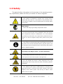
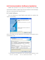
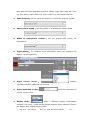
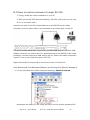
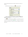
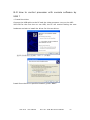
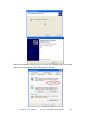
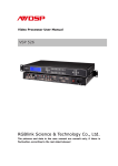
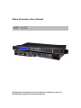
Video Processor User Manual
VSP 1121
The pictures and data in the user manual are reference only, any
modification please check with real device!
Revision
Format
1.0
Time
ECO#
Description
2012-01-31
0000
Release
Principal
CONTENT
1.0 Safety .......................................................................................................................................... 1 2.0 Specification ............................................................................................................................... 2 3.0 Parameters ................................................................................................................................... 3 4.0 Connection .................................................................................................................................. 5 4.1 VSP 1121 Back Panel.......................................................................................................... 5 4.2 VSP 1121 Size and installation ........................................................................................... 7 5.0 Front Panel Keyboard Operation ................................................................................................ 8 5.1 VSP 1121 Series Operator Guideline .................................................................................. 8 5.2 VSP 1121 Video Processor Menu ..................................................................................... 11 6.0 Communication Software Guideline ......................................................................................... 21 6.1 Install Software ................................................................................................................. 21 6.2 Run control software ......................................................................................................... 25 6.3 How to control processor through RS 232? .................................................................... 35 6.4 How to control processor with console software by USB ? .............................................. 37 7.0 Appendix ................................................................................................................................... 40 7.1 Appendix VSP 1121How to update the firmware ............................................................. 40 7.2 Appendix II Download the IP software ............................................................................. 42 8.0 Quick Start ................................................................................................................................ 44 8.1 Connection ........................................................................................................................ 44 8.2 Program buttons ................................................................................................................ 44 8.3 Adjust Image Size and Position......................................................................................... 45 8.4 Saving configs ................................................................................................................... 46 8.5 Recalling parameters ......................................................................................................... 46 1.0 Safety
The general safety information in this summary is for operating person.
Any requirement, please feel freely to contact our service engineer.
Power Source
This product is intended to operate from a power source
between 85~265 volts rms . This product is only workable under
correct power condition, which is already mark on the back panel
of the power.
High Voltage
There are many high voltage components inside.
Do not Remove Covers and Panels
Do not remove Covers in any conditions. There are not any
spare components inside for maintenance, so do not maintain
this product by userrselves, any requirement, please feel free to
contact our service engineer. Keep heavy device from power
cord.
Grounding the Product and Use the Proper Fuse
This product is grounded through the grounding conductor of
the power cord. To Avoid electrical shock, plug the power cord
into a properly wired receptacle before connecting to the product
input or output terminals.
Keep away from Magnet, Motor, TV and Transformer.
Guard Against Damp
Keep using inside clean and dryness environment, once the
device get wet, must remove power cord right now.
Keep away Exploder
Do not operate the device inside dangerous and easy
explosive gas, which it may make fire, blast or something without
expectation.
Keep away Pour Liquid and Fragment
It is forbid to pour liquid, metal fragment or anything else
inside this device to avoid fire and other accident. Once that
happens, must remove power cord and try to make it clean
before power on again.
VSP 1121
User Manual
Doc. No.:RGB-RD-UM-V1121E001
1
2.0 Specification
VSP 1121 is designed as a middle-end seamless video processor, which accepts a wide variety
of computer and HDTV video signals, including 4 Composite (CVBS ), 2 VGA( YPbPr
Compatible) input, 2 DVI(HDMI1.3 Compatible ), 1 DVI3(Only for background input ). It
combines truly seamless, glitch-free switching with advanced scaling technologies to meet
the requirements of high quality, high resolution video presentations. It has been designed
for presentation-enhancing features such as fade-in fade-out and wipe transition effect,
multiple output formats,
adjustable size and position of picture,multiple preset modes, PIP
modes, multiple control methods, image over background effect, which make VSP 1121 the
ideal seamless switcher to deliver
advanced
capabilities to high-end presentation
environments.
Features:
Processing:
• True Seamless switching
• High quality scaling technology
• 10-bit sampling and internal processing/scaling
• Short video delay
Multiple inputs
• VSP 1121 provides 4x Composite(CVBS) ,2XVGA( Compatible with YPbPr),
and 2xDVI (compatible with HDMI 1.3)
Multiple outputs:
• 1 x VGA output is provided for connectiong to a VGA-based monitor, using for preview.
• 2 X DVI outputs are provided for spliting into two different pictures or distributing the same
two pictures, the two DVI outputs can be connected with LED display or other display.
Programmable Operation
• VSP 112 includes of two channel inputs, the first channel can be selected from Mix CV1, CV2,
VGA1, DVI 1; the second channel can be selected from Mix CV3, CV4, VGA2, DVI2; That’s to
say, the channel are programmable, while users can also preview the output via VGA monitor.
Multiple Control Methods
Front Panel, RS232、USB, Etherent
VSP 1121
User Manual
Doc. No.:RGB-RD-UM-V1121E001
2
3.0 Parameters
CVBS Input
Number of Inputs
4
Connector
Standard BNC Socket
Supported Standards
PAL/NTSC
Signal Level
1Vpp±3db (0.7V Video+0.3v Sync ) 75 ohm
Multiplex
480i,576i
VGA Input
Number of Inputs
2
Connector
Standard DB9 Socket
Standards
VGA-UXGA
Signal Level
R、G、B、Hsync、Vsync:0 to1Vpp±3dB
(0.7V Video+0.3v
Sync ) 75 ohm
black level:300mV Sync-tip:0V
Supported Resolution
VGA-UXGA
(800*600@60,
1024*768@60,
1280*1024@60,
1440*900@60,1600*1200@60)
YPbPr Input
Number of Inputs
2
Connector
Standard DB9 Socket
Standards
Analog HD Input
Signal Level
Y:1Vpp±3dB
(0.7V
Video+0.3v
Sync
)
75
ohm
Pb/Pr:0.7Vpp±3dB 75 ohm
Supported Resolution
480i,576i,480p,576p,720p50,720p60,1080i50,1080p50
1080i60,1080p60
DVI Input
Number of Inputs
2
Connector
Standard DVI-I socket
SMPTE:625/25/50 PAL, 525/29.97/59.94 NTSC,
Standards
1080P50,1080P59.94/60,1080i50,1080i59.94/60,
720p50,720p59.94/60
VESA:800×600×60Hz,1024×768×60Hz,1280×768
×60Hz,
1280×1024×60Hz,1600×1200×60Hz,1920×1080×
60Hz
Signal Level
TMDS pwl,single pixel input,165MHz bandwidth
Standards
HDMI 1.3
Background Input
Number of Inputs
1
Connector
Standard DVI-I socket
VESA:800×600×60Hz,1024×768×60Hz,1280×768
Supported
VSP 1121
Input
User Manual
Doc. No.:RGB-RD-UM-V1121E001
3
Resolution
×60Hz,
1280×1024×60Hz,1600×1200×60Hz,1920×1080×
60Hz
Signal Level
TMDS pwl, single pixel input,165MHz bandwidth
Standard
DVI 1.0
USB Input
Number of Inputs
2
Connector
Standard USB connector
Format Supported
Picture:JPGE,BMP,PGN
Video:MPEG2,MPEG3, MPEG4,H264, RM,RMVB,MOV,
MJPEG, VC1,DivX,FLV
VGA Output
Number of Inputs
1
Connector
Standard DVI-I socket
VESA :
800×600×60Hz , 1024×768×60Hz ,
1024×768×75Hz ,1280×768×60Hz,1280×1024×60Hz,
1440×900×60Hz,1400×1200×60Hz,1600×1200×60Hz,
Supported
Output
Resolution
1920×1080×60Hz
R、G、B、Hsync、Vsync:0 to1Vpp±3dB
Signal Level
(0.7V Video+0.3v
Sync ) 75 ohm
black level:300mV Sync-tip:0V
DVI Output
Number of Output
2
Connector
Standard DVI-I socket
Signal Level
TMDS pwl, single pixel input,165MHz bandwidth
VESA:
800×600×60Hz
,
1024×768×60Hz
,
1024×768×75Hz ,1280×768×60Hz,1280×1024×60Hz,
1440×900×60Hz,1400×1200×60Hz,1600×1200×60Hz,
Supported
Output
Resolution
1920×1080×60Hz
Function
Input
channel
configuration
PIP
support each
input
channel signal programming
configuration
Support PIP、PBP for any two inputs
Transition effects
Fade in and fade out switching between any two inputs
Extras
Communication
RS232 USB TCP/IP
Power Supply
85-264V 2.1A IEC-3
Working Environment
0°C~45°C
Stored Environment
10% to 90%
Product Warranty
1year
VSP 1121
User Manual
Doc. No.:RGB-RD-UM-V1121E001
4
4.0 Connection
4.1 VSP 1121 Back Panel
1~4、Composite Video inputs, support audio signals from DVD player , Set-top
box , HD player sources via the BNC connector of 75 ohm;
5/6、VGA input interface, DB-15, used to support Analog RGB input;
7、Dial switch;
8、10/100M interface (copper RJ45).
9、USB interface to control processor by AVDSP PC software
10、RS232 interface to control processor by AVDSP PC software,
11/12/22/23、Gigabit copper port, connect to LED screen;
13/24、Gigabit Transmitter card power interface, not use inside case;
14/25、USB interface to control the sending card by LED studio or control
software;
15/26、Gigabit Transmitter card DVI input,connect to DVI output of VSP 112.
(This Connection does not support hot-plugging);
17/18、DVI input interface (HDMI 1.3 Compatible). Input the video signal from
computer, DVI signal generator, HD Player. Connect to the DVI 1 interface on
VSP 112(This Connection does not support hot-plugging;
VSP 1121
User Manual
Doc. No.:RGB-RD-UM-V1121E001
5
16、USB input interface, used to player media files from disk with USB connect
or. Such as USB disk, Portable Hard Disk; Note:Can be also used for online
update.
19、Back ground signal input(DVI), can be connected with Laptop,computer
video signal through DVI connector; ( Only accept standard computer
graphic DVI signal)
20、DVI output interface. Connect to the monitor or LED screen which has DVI
interface. (This Connection does not support hot-plugging)
21、DVI output from DVI +VGA connector, can be connected with DVI-based
Monitor or control system card for LED display. (This Connection does not
support hot-plugging).
VGA output of DVI+VGA, used to connect to connect to the monitor, projector
and so on;
20. Through adapter
and VGA output
, user can output both DVI
simultaneously.
Or through DVI-VGA
adapter to output VGA format
individually.
27、Power switch button.
28、Switch and power. It must use IEC-3 power line. Always ground to avoid
electric shock.
VSP 1121
User Manual
Doc. No.:RGB-RD-UM-V1121E001
6
4.2 VSP 1121 Size and installation
VSP 1121
User Manual
Doc. No.:RGB-RD-UM-V1121E001
7
5.0 Front Panel Keyboard Operation
Insert power cord and push power button to ON position. LCD module
on the front panel will show Video Processor and go into self verification before
it load the last setting config and send the processed image to the target display
or device. For the first running, CV1 input is the default input source. With the
front panel operation, users can operate the equipment with buttons and menu
displayed on LCD module.
5.1 VSP 1121 Series Operator Guideline
VSP 1121 front panel as following:
1 、 LCD panel,used to show button menu and menus for interactive
communication.
2、Menus:
SELECT: Press SELECT to confirm the current choice item or value;
UP: push to select up items or increase current setting value;
DOWN: push to select down items or decrease current setting value;;
3、Signals:
Program
1:Program Button 1,Press the button, its LED light turns on,Program output
will be swithced to this channel 1;
2:Program Button 2,Press the button, its LED light turns on,Program output
will be swithced to this channel 2;
3:Background Button 3,Press the button, its LED light turns on,Program output
will be swithced to this channel 3;
Button 1,Button 2,Button 3 are designed from left to right order.
Preview
VSP 1121
User Manual
Doc. No.:RGB-RD-UM-V1121E001
8
1:Preview Button 1,Press the button, its LED light turns on,Preview utput will
be swithced to the Programe Channel 1;
2:Preview Button 2,Press the button, its LED light turns on,Preview utput will
be swithced to the Programe Channel 2;
3:Preview Button 3,Press the button, its LED light turns on,Preview utput will
be swithced to the Programe Channel 2;
Button 1,Button 2,Button 3 are designed from left to right order;
Program guideline for Button 1, Button 2: Firstly: Press Preview
Button 1or Button 2;Secondly,Press
buttoon; Thirdly, LCD
panel will give message and ask users to select input source by
buttons. Press
pressing
to confirm; Fourthly, Press
to quit from program and finish.
Program out goes through the connector
, Preview
output goes through the connector DVI2
, DVI+VGA
output goes through cable
or use
,to output DVI and VGA video,
adapter to output VGA video.
4、Function
TAKE: seamless dissolving, press the button to to switch preview out to
Program Output with dissovlving transition effect;
PRG: Program Button, press the button to program for Button 1 and Button2
and Button 3.
Program guideline for Button 1, Button 2, Button 3: Firstly: Press
Preview Button 1or Button 2 or Button 3; Press
buttoon;
Thirdly, LCD panel will give message and ask users to select input
VSP 1121
User Manual
Doc. No.:RGB-RD-UM-V1121E001
9
source by pressing
Fourthly, Press
buttons. Press
to confirm;
to quit from program and finish.
Button 1 can program for any input of CV1,CV2,DVI1,VGA1
Button 2 can Program for any input of CV3, CV4, DVI2, VGA2,
Button 3 can program for DV3, TP.
SCALE: SCALE SIZE AND POSITION SETTING,Press the button and goes from
HsizeÆVsizeÆHPOSÆVPOS to set Size value and position value;
Push LEFT/RIGHT,and push UP/DOWN and SEL to confirm the relevant items;;
Scale Width:
*1920
Scale Height:
*1080
Scale Pos X:
*0
Scale Pos Y:
*0
MENU: Advanced menu , Press the MENU to enter the main menu, the
submenus: Device information, Factory Reset, Languageand Alpha setting are
all included. Push the LEFT/RIGHT to select the relevant submenu.
SAVE: Saving Button, press the button, its light turns on, push the lighting
button to save config to(SAVE1)or
VSP 1121
User Manual
to(SAVE2).
Doc. No.:RGB-RD-UM-V1121E001
10
5.2 VSP 1121 Video Processor Menu
While VSP 1121 is initializing, the following messages will be displayed on the
LCD panel.
亮彩系列
AVDSP Series VSP1121
Wait Init Network…
VSP 1121 can be connected via network cable to the LAN, but when the device
is not connected to the network, there will be a prompt: DHCP Failed;
The device does not show DHCP Failed when you access the network: as
following:
DHCP Failed
When connected with network successfully, it will get a IP automatically. Like
menu as following
IP Address
192.168.1.100
Press【MENU】button go to main menu,as followings:
VSP 1121
*DEV INFO
RESET
The first line shown on LCD is VSP 1121. Select DEV Info (i.e.: Device
Information and serial number) to show relevant information about current
input. As following:
Program 1 : DVI1
1920x1080X60
Preview 2 : DVI 2
1920x1080X60
Output Format:
1920x1080X60
Software version:
0.2
VSP 1121
User Manual
Doc. No.:RGB-RD-UM-V1121E001
11
Video Processor
SN:*****
Push【MENU】to escape from the current menu and go back to the main
menu,as following; Press 【DOWN】 and select Reset submenu. Press SEL.
>VSP 1121
Dev Info
*Reset
After successful reset you will see the menu as follows:
Reset Finished
Push【MENU】to go back to the main menu, and Press【DOWN】 to find
LANGUAGE.
Submenu:
>VSP 1121
*Language
OUT
Press 【SEL】 select the relevant submenu. LANGUAGE submenu as follows:
* Language select
> English
中文
Press 【DOWN】 to select the LCD language.
Press 【MENU】to go back the main menu,Press 【DOWN】,select
>VSP 1121
Language
OUT menu;
* OUT
Press【SEL】and enter the corresponding sub-menu settings;
OUT
>Format
DE
Press【SEL】,go to Out Format as following:
Out Format
>1024 x 768 x60
VSP 1121
User Manual
Doc. No.:RGB-RD-UM-V1121E001
12
VSP 1121 support 5 resolutions:1024 x 768 x60;1280 x 768 x60;
1280 x 1024 x60;1600 x 1200 x60;1920 x 1080 x60;
Press【SEL】,select the output resolution you need;
Push 【MENU】to go back to the main menu,push 【DOWN】,select OUT
(output connector setting);
OUT
Format
>DE
OUT DE
>Program
Preview
Push 【SEL】,and enter the corresponding sub-menu to set DE switch ; go
to program sub-menu as shown:
Program
>DE Setup
HDMI/DVI
Program DE
>ON
ON/OFF
Press【ON】
,and Press【SEL】to go to DE setting menu,Press【UP】 or【DOWN】
to change the value.
> Program DE H Start
*35
Or Press 【DOWN】,scroll down the menus,as following:
> Program DE H Start
> 35
> Program DE V Start
> 35
> Program DE Width
> 1920
> Program DE Height
> 1080
DE H Start: horizontal axis setting; DE V Start: vertical axis setting;
VSP 1121
User Manual
Doc. No.:RGB-RD-UM-V1121E001
13
DE Width: width setting; DE Height: height setting;
Likewise, above operation can also be applied for setting Preview DE ;
Push【MENU】button to go back to previous menu,push 【DOWN】,select
HDMI/DVI output settings;
Program
DE Setup
>HDMI/DVI
Press 【 SEL 】 , enter the HDMI/DVI settings for output signal; go
to sub-menu HDMI/DVI as shown:
Program HDMI/DVI
>HDMI
DVI
Likewise, above operation can also be applied for setting Preview output。
Press 【MENU】to return to the previous menu,Press 【UP】 or 【DOWN】,
scroll the menus;
And find the menu (Time) and(Calendar);
>VSP 1121
*Time
Calendar
Press【SEL】to enter Time setting;
Time
> 00:00:20
Press【SEL】 to activate the Time setting, if there is a * sign, means the menu
item has been selected; press 【UP】and 【DOWN】 to revise the time.
Time
*00:00:20
Press 【MENU】to return to the previous menu,Press 【UP】 and 【DOWN】,
find the Calendar as following;
>VSP 1121
Time
* Calendar
Press 【SEL】to enter Calendar setting;Date shows on the left side,Day shows
on the right side.
VSP 1121
User Manual
Doc. No.:RGB-RD-UM-V1121E001
14
Calendar
>2010/01/01
Sun
Press 【SEL】 to activate the Calendar setting, if there is a * sign, means the
menu item has been selected,Press【UP】 or【DOWN】 to change the value;
Calendar
*2010/01/01
Sun
Press 【MENU】to return to the previous menu,scrolling the menu,find the
Scale menu:
>VSP 1121
* Scale
Advance
Press 【SEL】 to enter the Scale setting, Scale menu means the zoom menu,
including the following settings:
Scale Width: Scale in horizontal.
Scale Width CH2:
>1024
Scale
Height:Scale in vertical
Scale Height CH2:
>768
Scale Pos X: Scale X position
Scale Pos X CH2:
>0
Scale Pos Y: Scale Y position
Scale Pos Y CH2:
>0
Scaling setting only effects for program ouput channel,while
preview is always shown in fullscreen. Users can modify the
scaling parameters so as to resize the image and position shown
in LED display.
Press 【MENU】, return to the main menu , scrolling to find Advance submenu;
VSP 1121
User Manual
Doc. No.:RGB-RD-UM-V1121E001
15
>VSP 1121
Scale
* Advance
Set values for screen parameter and aspect ratio.
Advance setting
>Screen
Press 【SEL】,enter the advance menu, push 【DOWN】, to find Screen:
Screen width:set the horizontal size of the screen;
Screen height:set the vertical size of the screen;
Screen pos X:set the horizontal position of the screen;
Screen pos Y:set the vertical position of the screen;
User can set size and position of the screen simply, Mainly applies to LED
screens users. After setting screen parameter, display picture can directly
shows on corresponding screen.
Screen width :
>1024
Screen height :
>1024
Screen pos X :
>1024
Screen pos Y :
>1024
Advance includes the ratio setting menu:
Advance setting
>other
Normal ratios are 4:3 and 16:9, Press 【UP】and 【DOWN】to realize the
convertion between the two types.
Preview -program swap is to switch between the main picture and subpicture.
Press 【MENU】, return to the main menu , press 【DOWN】 and find Picture
submenu.
VSP 1121
User Manual
Doc. No.:RGB-RD-UM-V1121E001
16
>VSP 1121
*Picture
BG
Press 【SEL】,enter the Picture submenu, Picture quality can be revised by the
following options:
Set Brightness:To change the brightness value of picture
Set Contrast:to change the contrast value of picture,
Set Saturation:To change the Saturation value of picture
Set Color Red :To change the Red color value of picture;
Set Color Green:To change the Green color value of picture;
Set Color Blue:To change the Blue color value of picture;
Users can adjust the settings according to the actual situation, this function is
mainly applied to the technician who is very professional at the image quality.
However, if there is any improper operation and image quality errors or
distortion occur, reset the device from main menu Recall.
Press 【MENU】,return to the main menu, press DOWN to set BG (Background).
>VSP 1121
Picture
* BG
Push SEL key,to configure BG, as following:
Background
>TP
Background
>DVI3
Background channel comes with TP test pattern picture and background
input DVI3.
Press 【MENU】,return to the main menu, press UP/ DOWN to set 【AB Mode】
transition effects;
>VSP 1121
*AB Mode
PIP
【AB Mode】:full screen cut,full screen transparent switch,wipe,transparent
VSP 1121
User Manual
Doc. No.:RGB-RD-UM-V1121E001
17
wipe.
Wipe and transparent wipe both offer six ways of seamless switch
transparent wipe along with soft effect.
Push 【 DOWN 】 ,
make
(AB
Mode)
menu
selected:
CUT
Switch,
non-transparent mode, wipe right,wipe down, wipe up, wipe square in/out,wipe
center out,
transparent DISSOVLE Switch mode.
Setup AB Mode
> CUT Switch
Setup AB Mode
> DISSOVLE Switch
Press 【SEL】to enter the fade switch to confirm the time setting;Press【UP】
or【DOWN】to adjust the duration of dissolve effect, which ranges “0.5 s-30.0 s”.
Dissolve Duration:
>3.0 s
Press 【SEL】to enter(WIPE HARD Switch) setting;
Setup AB Mode
> WIPE HARD Switch
Setup AB Mode
> WIPE SOFT Switch
Press 【UP】 or【DOWN】,can check the multiple seamless transition effects:
WIPE Mode
> WIPE RIGHT
WIPE Mode
*WIPE LEFT
WIPE Mode
*WIPE DOWN
WIPE Mode
*WIPE UP
VSP 1121
User Manual
Doc. No.:RGB-RD-UM-V1121E001
18
WIPE Mode
*WIPE PLUS OUT
WIPE Mode
*WIPE CURTAIN OUT
WIPE Mode
*WIPE CENTER OUT
Press 【MENU】,return to the main menu,Press【UP】 or【DOWN】
,find PIP
setting option;
VSP 1121
AB Mode
*PIP
Go into the PIP setting as following:
PIP
OFF
*ON
Press 【MENU】,return to the main menu, Press【DOWN】and set【Matrix】
VSP 1121
*Matrix
TP
Matrix is only for output signal. The DVI1 OUT can be set to be previewed or
to be programed. The same operation can be applied for DVI2 OUT ,VGA OUT
setting.
DVI1 OUT
>Program
DVI1 OUT
>Preview
DVI2 OUT
>Program
DVI2 OUT
>Preview
VGA OUT
>Program
VSP 1121
User Manual
Doc. No.:RGB-RD-UM-V1121E001
19
VGA OUT
>Preview
Push【MENU】,return to the main menu, Press【DOWN】and set【TP】for picture.
TP MODE
>Auto color
Push 【SEL】,the device will do the color change testing automatically, push
to set time duration for change.
TP MODE
Manual color
Push 【SEL】,test the color change manually, and set the RGB value.
Six rolling test bars, 2 striped test pattern and 2 gray-scale images test pattern
are offered to satisfy the test for gray and color of LED screen.
VSP 1121
User Manual
Doc. No.:RGB-RD-UM-V1121E001
20
6.0 Communication Software Guideline
AVDSP video processor is very easy to be configured with user friendly
communication software, support drag and drop operation for edit and display.
Also can be customized with schedule function.
6.1 Install Software
Dual click AVDSP.exe to install, English version default for use,after click
“select ”to next dialog.
And in next dialog is the user agreement of the software, click Agree to go on
and Disagree to exit.
If users agree to the agreement, user can select install directory in next
VSP 1121
User Manual
Doc. No.:RGB-RD-UM-V1121E001
21
dialog, else, click next to install software to default directory “C:\Program Files”
Click “next”to go on.
Click “next” to go on.
VSP 1121
User Manual
Doc. No.:RGB-RD-UM-V1121E001
22
VSP 1121
User Manual
Doc. No.:RGB-RD-UM-V1121E001
23
Click “finish” and ready to run AVDSP console.
VSP 1121
User Manual
Doc. No.:RGB-RD-UM-V1121E001
24
6.2 Run control software
Install communication software which comes with packages of VSP 1121
device. Double click AVDSP.EXE icon from home screen to run the software VSP
1121 communication software interface as shown:
z
Set up communication
Serial is the default COM,For the first running ,user must click the
to refresh
COM Port, select the right COM port,
Serial: user can make choice between existent com ports and baud rates;
default Baudrate is 115200.After setting Baudrate, click the
start communication, the button
communicated, the prompt
VSP 1121
User Manual
will turn into
button to
if sucessfully
will show on the left bottom.
Doc. No.:RGB-RD-UM-V1121E001
25
Ethernet: user can fill any number less than 1023 in Local Port. The Remote Port
must be 192.168.0.100 and the Remote Port must be 1000. After setting
Baudrate, click the
turn into
button to start communication, the button
will
if successfully communicated, the prompt
will
show on the left bottom.
Mode Control:
Operator Interfaces as following:
VSP 1121
User Manual
Doc. No.:RGB-RD-UM-V1121E001
26
Left part is preview window ,input signal information will be shown on the top
left corner
,showing signal types and its resolution,
corresponds with preview channels,
the button part’s button
Green-colored button indicates the button is selected. Preview image can be
switched by button, in order to preview the 3 channels.
Right part is program window, input signal information will be shown on the top
, showing signal types and its resolution
left corner
the
button
part
buttons
correspond
with
program
channel ,program output image can be switched by button ,also can drag and
drop the image to adjust the size and position of the program output signal
z
Output resolution toolbar:
User can choose three output resolution by selecting from scrolling down list;
z
Switch mode:press switch,after take button is effected ,program output
image will switch with preview image , Press remain, after take button is
effected, program out will follow the image of preview.
z
Recall saving configs:click the buttons as followings to load the configs.
VSP 1121
User Manual
Doc. No.:RGB-RD-UM-V1121E001
27
z
PIP Switch:
switch between main image and
sub-image.
z
FS:
switch between full screen and scaled screen, scaling can be
realized through screen parameters setting.
z
CUT:
seamless CUT effect button, will switch preview image to
program output;
z
Take:
eamless transition effects button,will switch preview image
to program output with special effects;
z
Effects Toolbar:
z
The device not only provides the most common fade effects(in default),but
VSP 1121
User Manual
Doc. No.:RGB-RD-UM-V1121E001
28
also other fourteen seamless transition effects: wipe right ,wipe left ,wipe
up, wipe down, wipe center out, wipe curtain out ,wipe square out etc.
z
Fade duration:Set the value for duration(1-30s)from progress toolbar.
z
Switch effect speed :set the grades(1-16 grades)for switch speed
z
Width of transparent toolbar: : set the pixels(0-255 pixels) for
transparent;
z
Input setting :To configure input information, Users can configure for
input1, input2 separately:
z
Input
source
support
choice :
CV,YPbPr,VGA,DVI,USB total five sources.
z
Input resolution toolbar:
shows the resolution of
current input source.
z
Display mode :
offers 2 different display modes,when
selected “live video “,video will be played normally when selected “freeze”
the display only shows the last frame.
VSP 1121
User Manual
Doc. No.:RGB-RD-UM-V1121E001
29
z
Ratio:
choose 4:3 or16:9 from scrolling down list.
z
Mode configuration:
Single picture mode
PBP mode:
z
PIP mode:
PDP up and down:
Image input toolbar:VSP 1121 is a three-layer processor; the data of
each layer can be set from this toolbar. Data can be input at any combination,
i.e., the three different channels. That is what we call “matrix functions”. Scale,
zoom, crop can be realized by entering the value or rolling down the list, or drag
VSP 1121
User Manual
Doc. No.:RGB-RD-UM-V1121E001
30
and drop the picture.
z
Set:
z
Save :
click 【set】button each time to confirm the setting.
click【save】to save all the revised parameters,the
scrolling list indicates the location to be saved to, if successfully saved, user
can call it anytime in the future。
z
Update reset :
z
Output matrix
VSP 1121
User Manual
click this button to recall the factory setting。
Doc. No.:RGB-RD-UM-V1121E001
31
output connector can be set as program output or preview output at will.
z
Control:
z
Device update
is used to update 100M communication program online.
z
Layout:
VSP 1121
User Manual
Doc. No.:RGB-RD-UM-V1121E001
32
Layout setting is for Program output picture, ”Single” to show single
picture,”PIP”-picture in picture,PBP-Picture by Picture,
z
DVI DE delay :
Set the DE of DVI 1 and DVI 2 output, Nonprofessional technician is
recommended not to do this.
z
VGA input adjust :
To solve the problem that the VGA picture can be shown to the full screen or
problem of excursion. Nonprofessional technician is recommended not to do
this.
z IP set
Users can set equipment IP, Usually used under the condition of one
Computer control or remote control several computers. It takes effect after
VSP 1121
User Manual
Doc. No.:RGB-RD-UM-V1121E001
33
users change the IP by serial port, But if by the Ethernet to change IP, users
need to shut down communication software, and rerun the software.
z
Factory reset :click “factory reset”, previously saved user-mode will be
cleared。
z
Information toolbar:the button line of the interface of control software
shows the software version ,main chip version,hardware version and SN
z
Option :Language choices: English and Chinese.
z
Administration:Advance , for administrator control.
”Advance“ is for professional engineer specially, please contact
with our customer service engineer to get the code if it is
necessary;
z
Help: Display helps dialogue.
z
Version notice: Display the software version and
z
About:Display the software version and company information;
VSP 1121
User Manual
what is new;
Doc. No.:RGB-RD-UM-V1121E001
34
6.3 How to control processor through RS 232?
1. Firstly, install the control software in your PC;
2. Take out the RS 232 cable as following(RS-232, with 9-pin on one end,
RJ 11 on the other side.)
Connect one side of the RJ11 download line to the RS232 on the video
processor, and the other side to be connected to the serial port on the PC.
If there is no any Serial port on your PC, you will need another Serial to USB
adapter. Connect one end of the RJ11 download line to the RS232 on the video
processor. Connect the end of USB-side to the PC, Ensure the cable connection
is good. Turn on the Video Processor VSP 729.
Right click the【My Computer】on the home screen of control PC.
Enter【Attribute】,Find【Hardware】Option,as following,Click【Device Manager】
“+” on the left,check the COM number,as following, COM1 is offered.
Remember the COM you are using and then run the control software,find
VSP 1121
User Manual
Doc. No.:RGB-RD-UM-V1121E001
35
【Communication】 option,Click Com button, buttons will turn green. As
following:
In defaut,first time user have to click
button,as following:
Check and tap【Serial】,【Serial Port , for example,is COM1 which is
checked from device manager. Set VSP 628 Boud Rate to be :115200,Click
【Confirm】after setting.
Click
【 open serial】,check if【COM】icon on the bottom right corner
when there is the promt green
showing on the sofwware, it
means the communication is ok ,and you can use the software to control the
device now ;
VSP 1121
User Manual
Doc. No.:RGB-RD-UM-V1121E001
36
6.4 How to control processor with console software by
USB ?
1. Install the driver
Connect the USB cable to the PC and the video processor .turn on the VSP
VSP 628 for the first time to use USB, the PC will remind finding the new
hardware and ask to install the driver for this new driver.
选择从列表或指定位置安装,单击“下一步”继续:
Install from the list or specified location, press “NEXT”
VSP 1121
User Manual
Doc. No.:RGB-RD-UM-V1121E001
37
When the installation finish,can go to check the installed COM port inside
the device mangement ,as following picture shows:
VSP 1121
User Manual
Doc. No.:RGB-RD-UM-V1121E001
38
2. Install the console software, and run after install, show the interface of the
console as following: Select the COM as installed just now, and set the VSP 1121
Boud Rate to be :115200
Press
to start communication,when there is green point in
the right down corner showing on the sofwware, it means the communication
is ok ,and you can use the software to control the device now;the software
operation is the same as VSP1121.
If power off during communication, should close the port
by first , and plug in out of the USB and do communication
again
VSP 1121
User Manual
Doc. No.:RGB-RD-UM-V1121E001
39
7.0 Appendix
7.1 Appendix VSP 1121How to update the firmware
1. Firstly, connect the device with PC by network cable (Cat 5 cable).
2. Input VSP 1121 network address in address bar: 192.168.0.100, enter the
user name admin and password rgblink123 in the dialog box
3. Thirdly, click on FPGA Upgrade:
VSP 1121
User Manual
Doc. No.:RGB-RD-UM-V1121E001
40
4. Fourthly, click on【browse】to select upgrade, file name must be
Preamp_FPGA.bin or Bakamp_FPGA.bin.
5. Click 【Send】to send and wait for upgrade
6. Upgrade Bakamp FPGA Successfully.
VSP 1121
User Manual
Doc. No.:RGB-RD-UM-V1121E001
41
7.2 Appendix II Download the IP software
Turn off the power, take the two coding switch to “ON” sate. As below:
Connect one side of the RJ11 download line to the RS232 on the video processor,
and the other side to be connected to the serial port on the PC.
Double click
to run Flash Magic ,setting as below:
First, users can choose the right serial port, set the baud rate to 115200, choose
LPC2368,and to load the aim document (hex.document) of IP board upgrading.
Secondly, confirm the two option box by tick.
Finally, click the “Start” button.
VSP 1121
User Manual
Doc. No.:RGB-RD-UM-V1121E001
42
After download, exit the program, turn off the power, tack the two coding switch
back, as below, restart the equipment power, check if the equipment work
normally.
Flash Magic download website:
http://www.flashmagictool.com/download.html&d=FlashMagic.exe
VSP 1121
User Manual
Doc. No.:RGB-RD-UM-V1121E001
43
8.0 Quick Start
8.1 Connection
a. Power Connection. Connect an AC power @ 90-264V 50/60Hz to the ACE Power
connector on the rear of VSP 1121, and then to an AC outlet.
b. Input Connection. Connect the input sources to the corresponding connector.
8.2 Program buttons
How to program the inputs
For example, If suppose to define Button 1 to be DVI1 and Button 2 to be DVI2,
please push Button1 or Button 2 in preview button area,then press Program
(PROG)
Button,the LCD panel will show INPUT 1 as below:
INPUT 1
>DVI1
Press 【UP】and 【DOWN】,select the input source,after pushing 【SEL】,the
blinking button indicate that you have successfully programmed.
Or push Program(PROG)
Button, all the programmable channel buttons
turn on. Follow the silk print instructional characters, select the signal you want
and push the button to confirm,the blinking button indicate that you have
successfully programmed.
VSP 1121
User Manual
Doc. No.:RGB-RD-UM-V1121E001
44
8.3 Adjust Image Size and Position
To adjust the image size, Press Button SCALE,LCD panel asks you to
activate ,as following:
Scale Width:CH1
*1920
Press 【SEL】 to confirm the submenu, then press 【UP】 and 【down】to modify
the HSIZE value, press 【SCALE】to finish modifying. Press 【UP】 and 【down】
to find the submenu Scale Height modify the Height value.
Scale Height:CH1
*1080
Press 【SEL】 to confirm the submenu, then press 【UP】 and 【down】to modify
the Height value, press 【SCALE】to finish modifying. Press 【UP】 and 【down】
to apply the same operation to Pos X, Y modifying.
Scale Pos X:CH1
*0
Scale Pos Y:CH1
*0
VSP 1121
User Manual
Doc. No.:RGB-RD-UM-V1121E001
45
8.4 Saving configs
After configuration, press 【SAVE】to finish saving configs. A related message
will be shown on the LCD panel asking you to Press Menu To Exit.
SAVE Setting To:
Press Menu To Exit
VSP 1121 offers 2 lighting Save buttons,users can select the saving destination
by pressing【SAVE1】or【SAVE2】button.
SAVE Setting To:
SAVE1 finished
Preset inputs, image size and position can be programmed and
saved, so users can recall configs in the future.
8.5 Recalling parameters
VSP 1121 offers 2 saving modes,i.e.: SAVE1 and SAVE2. Press the Saving
Button which has stored the parameters configured, the LCD panel will show the
message as following:
Load Setting From:
SAVE1
Finished
VSP 1121
User Manual
!
Doc. No.:RGB-RD-UM-V1121E001
46