
1
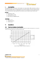
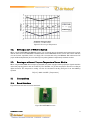
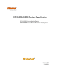
DAT5280 Ambient Temperature Sensor Module
User Manual
Version: 1.0.2
Feb. 2004
Table of Contents
I.
Introduction
2
II.
Operations
2
II.1.
Typical performance characteristics
2
II.2.
Running as part of WiRobot System
3
II.3.
Running as a General Purpose Temperature Sensor Module
3
III.
Connections
3
III.1.
Board Structure
3
III.2.
Connector Description
4
IV.
Specifications
4
Related Document:
WiRobot PMS5005 Sensing and Motion Controller User Manual
Copyright © Dr Robot Inc. 2003.
1
I.
Introduction
The DAT5280 Ambient Temperature Sensor Module uses high-precision CMOS temperature sensor to
generate linear voltage signal according to the ambient air temperature. With a temperature coefficient of 25.5
mV/˚C and nonlinearity of ±0.5 %, the DAT5280 is superior in the functionality over conventional temperature
sensors like thermometers. Typical applications include robotic system and high-precision thermal control.
Features
• High linearity: ± 0.5%
• Standard output: 0 – 3.3V
• High temperature accuracy
• Plug-and-play in the WiRobot system
Applications
• Robotic system
• Temperature sensing
• Thermal control
II.
Operations
II.1.
Typical performance characteristics
The performance characteristics are shown in the figures II.1 and II.2. If needed, the temperature accuracy error
could be removed by calibration on the individual module basis.
Figure II.1 Output Voltage vs Ambient Temperature
Copyright © Dr Robot Inc. 2003.
2
Figure II.2 Accuracy vs Temperature
II.2.
Running as part of WiRobot System
When using the DAT5280 with WiRobot system, user can simply connect the module to the temperature sensor
module connector on the PMS5005 controller board and the PMS5005 built-in sensor device driver will take
care of the data acquisition. Users can simply call a function offered by the WiRobot SDK software on PC
(requires Microsoft platform) or send a data request packet (platform independent) to obtain the data.
II.3.
Running as a General Purpose Temperature Sensor Module
When using the DAT5280 with a third party controller, the power supply and the input/output signals should be
connected properly (please refer to Section III). The controller can get the temperature data via an analog to
digital converter. The temperature reading can then be calculated according to Figure II.1 or the following
equation
TV (in V) = 0.92 + 0.0255 * (Temperature)
III.
Connections
III.1.
Board Structure
Figure III.1 illustrates the structure of the board.
Figure III.1 DAT5280 Structure
Copyright © Dr Robot Inc. 2003.
3
III.2.
Connector Description
The DAT5280 can be connected to the controller system via a 3-pin 2.54 mm-pitch single row connector.
Table III.1 Temperature Sensor Connectors
IV.
Pin
1
2
Name
VCC
TV
3
GND
Function
Positive power source, 5 V DC
Temperature voltage, analog signal
output
Power ground
Specifications
Table IV.1 DAT5280 Specification
Parameter
Power Supply Voltage
Current Consumption
Nonlinearity
Temperature Sensitivity
Board Size
Copyright © Dr Robot Inc. 2003.
Conditions
Vcc = 5 V
-20˚C ~ +80˚C
-20˚C ~ +100˚C
MIN
4.9
4.66
TYP
5.0
MAX
5.1
5.0
±0.5
25.5 26.34
30 x 24
Unit
V
mA
%
mV/˚C
mm x mm
4


![[P/N: MCB3101] Class I Serial Bluetooth Wireless](http://vs1.manualzilla.com/store/data/005819698_1-328d04723caa8571829b907b8cc9e0c6-150x150.png)