1
WiRobot SDK Application Programming
Interface (API) Reference Manual
- (For MS Windows)
Version: 1.3.0
January 2010
Table of Contents
Convention ...................................................................................................................................... 3
WiRobot SDK Overview ................................................................................................................ 4
WiRobot SDK API Reference for PMS5005.......................................................................... 6
III.1.
Sensor Peripherals ................................................................................................................................ 6
III.1.1.
Batch Sensor Data Updating API ............................................................................................ 6
III.1.2.
Range and Distance Sensors .................................................................................................... 9
III.1.3.
Human Sensors .......................................................................................................................... 10
III.1.4.
Tilt and Acceleration Sensor.................................................................................................... 11
III.1.5.
Temperature Sensors ................................................................................................................ 12
III.1.6.
Infrared Remote Control Handling ......................................................................................... 13
III.1.7.
Battery Voltage Monitors........................................................................................................ 14
III.1.8.
Potentiometer Position Sensors ............................................................................................ 15
III.1.9.
Motor Current Sensors..............................................................................................................16
III.1.10.
Encoder ......................................................................................................................................... 17
III.1.11.
Custom Analog and Digital Inputs and Outputs ..................................................................18
III.2.
Motion Control ......................................................................................................................................20
III.2.1.
DC Motor Control.......................................................................................................................20
III.2.2.
RC Servo Motor Control ........................................................................................................... 31
III.3.
Multimedia Control............................................................................................................................... 34
III.3.1.
LCD Display ................................................................................................................................ 34
III.4. Events ..................................................................................................................................................... 34
IV.
WiRobot SDK API Reference for PMB5010 ........................................................................ 36
IV.1.
Multimedia Control............................................................................................................................... 36
IV.1.1.
Audio Input and Output............................................................................................................ 36
IV.1.2.
Image Capturing ......................................................................................................................... 38
IV.1.3.
LCD Display ................................................................................................................................ 39
IV.2. Events ..................................................................................................................................................... 39
V. Power Controller API ................................................................................................................. 40
V.1.
short GetVolRef( ) .............................................................................................................................. 40
V.2.
short GetBat1Vol( ) ............................................................................................................................ 40
V.3.
short GetBat1Temp( ) ........................................................................................................................ 40
V.4.
short GetBat2Vol( )............................................................................................................................ 40
V.5.
short GetBat2Temp( ) ........................................................................................................................ 41
V.6.
short GetDCINVol() ............................................................................................................................. 41
V.7.
byte GetCHGPath( ) ............................................................................................................................ 41
V.8.
byte GetPowerPath( ) ........................................................................................................................ 41
V.9.
byte GetCHGStatus( )......................................................................................................................... 42
V.10. void SendCmdCHG( ) .......................................................................................................................... 42
VI.
Constellation system API ....................................................................................................... 44
I.
II.
III.
Copyright © Dr Robot Inc. 2008
1
VI.1.
VI.2.
VI.3.
VI.4.
VI.5.
VI.6.
VI.7.
VI.8.
VI.9.
VI.10.
VI.11.
VI.12.
VI.13.
VI.14.
short GetGPS01( ) .............................................................................................................................. 44
short GetGPS02 ( ) ............................................................................................................................ 44
short GetGPS03 ( ) ............................................................................................................................ 44
short GetGPS04 ( ) ............................................................................................................................ 44
short GetGPS05 ( ) ............................................................................................................................. 45
short GetGPS06 ( ) ............................................................................................................................. 45
short GetGPS07 ( ) ............................................................................................................................. 45
short GetGPS08 ( ) ............................................................................................................................. 45
void setGPSID(Byte id1, Byte id2, Byte id3, Byte id4) ..............................................................46
byte getSenID1 ( ) ..........................................................................................................................46
byte getSenID2 ( ) ..............................................................................................................................46
byte getSenID3 ( ) .........................................................................................................................46
byte getSenID4 ( ) ......................................................................................................................... 47
Example of using the Constellation system .............................................................................. 47
Copyright © Dr Robot Inc. 2008
2
I.
Convention
Data Type
int:
UWord16:
short:
16 bit signed interger
16 bit unsigned interger
16 bit signed interger
Syntax
Syntax under each API reference is based on the C/C++ calling convention. Corresponding Visual
Basic calling convention can be found in relevant VB reference book, or from the WiRobot VB code
examples.
Copyright © Dr Robot Inc. 2008
3
II.
WiRobot SDK Overview
WiRobot Software Development Kit (SDK) is a part of the WiRobot development system. Being a PCbased software framework for robotic system development, the SDK contains the facilities for
memory management, system communication and user interface, and the utilities for audio, video
input/output, sensor data acquisition and motion control. Please refer to the WiRobot PMS5005,
PMB5010, or DRK6000/8000 User Manuals for the detailed information on the SDK architecture,
organization and system programming.
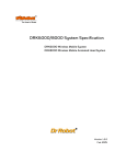
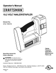
Under the WiRobot system architecture, all the controllers are connected in a chain. Programs
developed using WiRobot SDK runs on the Host as the central controller of each chain. All the
embedded controllers have at least two SCI ports for the system communications: upper-reach port
and lower-reach port, with the direction respect to the central controller. The WiRobot system
controller-level connection architecture is shown as Figure II.1.
Figure II.1 WiRobot System Architecture
The APIs described in this manual are the interface between the application-level software and the
WiRobot hardware system. Programs developed using WiRobot SDK runs on the PC sending and
receiving data to and from the WiRobot hardware via wire or wireless connection. The firmware on
the embedded controllers take care of all the low level operations of the system functional modules,
such as data acquisition, fast-loop low level motion control, image and audio capture and compression,
audio playback and wireless communication. They are transparent to the high level software system
running on the central PC controller. All the system software development can be carried on solely
under user-friendly PC system. WiRobot SDK for Windows is available for MS Visual C++ and MS
Visual Basic environment.
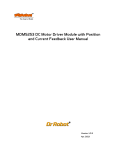
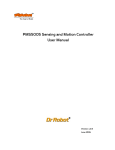
API exists as a MS ActiveX component, called “WiRobot SDK ActiveX Module”. User program uses
this component in VB or VC++ program to communicate with the WIRobot PMS5005 or/and
PMB5010 controllers. Data in between WiRobot hardware and the “WiRobot SDK ActiveX Module”
Copyright © Dr Robot Inc. 2008
4
is managed and transferred by the supplied WiRobot Gateway Program (WiRobotGateway.exe) with
the shared memory as shown in Figure II.2.
Figure II.2 WiRobot Software Architecture
Copyright © Dr Robot Inc. 2008
5
III.
WiRobot SDK API Reference for PMS5005
WiRobot SDK APIs for PMS5005 are grouped under the categories of Sensor Peripherals, Motion
Control, Multimedia Control and Events.
III.1.
Sensor Peripherals
This section contains the APIs for the operations of different sensor peripherals.
III.1.1. Batch Sensor Data Updating API
Standard Sensors: Sonar, human, infrared range, tilt/acceleration, temperature, battery voltage and
infrared remote control receiver
Motor Sensors:
Potentiometers, current feedback sensors and encoders.
Custom Sensors:
Custom expansion A/D inputs and digital inputs.
1
2
3
4
void SystemMotorSensorRequest(int PacketNumber);
void SystemStandardSensorRequest(int PacketNumber);
void SystemCustomSensorRequest(int PacketNumber);
void SystemAllSensorRequest(int PacketNumber);
Description:
SystemMotorSensorRequest sends a request command to the WiRobot Sensing and
Motion Controller (PMS5005) in order to get the sensor data related to motor control.
SystemStandardSensorRequest sends a request command to the WiRobot Sensing and
Motion Controller (PMS5005) in order to get all the WiRobot standard sensor data.
SystemCustomSensorRequest sends a request command to the WiRobot Sensing and
Motion Controller (PMS5005) in order to get all custom-sensor data,
SystemAllSensorRequest sends a request command to the WiRobot Sensing and Motion
Controller (PMS5005) in order to get all the sensor data.
Syntax:
SystemMotorSensorRequest (PacketNumber); // motor related sensors
SystemStandardSensorRequest (PacketNumber); // standard sensors
SystemCustomSensorRequest (PacketNumber); // custom sensors
SystemAllSensorRequest (PacketNumber);
// all the sensors
Parameter:
short PacketNumber;
The meanings of PacketNumber as follows:
Parameter
Action Requested
PacketNumber = 0
Stop sending the sensor data packets
PacketNumber = -1
Send sensor data packet continuously until being asked to
stop
PacketNumber > 0
Send n = PacketNumber packet(s) of sensor data and then
stop sending
Return value: void
Copyright © Dr Robot Inc. 2008
6
Remarks:
1. The default update rate is 20Hz. User can set up the data refresh rate according
to real system requirements.
2. System is default to continuously sending all data when bootup.
See Also: SetSysMotorSensorPeriod, SetSysStandardSensorPeriod,
SetSysCustomSensorPeriod, SetSysAllSensorPeriod.
5
6
7
8
void EnableMotorSensorSending ();
void EnableStandardSensorSending ();
void EnableCustomSensorSending ();
void EnableAllSensorSending ();
Description:
EnableMotorSensorSending enables batch updating motor-related sensor packets.
EnableStandardSensorSending enables batch updating standard sensor packets.
EnableCustomSensorSending enables batch updating custom sensor packets.
EnableAllSensorSending enables batch updating all the sensor packets.
Syntax:
EnableMotorSensorSending();
EnableStandardSensorSending ();
EnableCustomSensorSending ();
EnableAllSensorSending ();
// motor related sensors
// standard sensors
// custom sensors
// all the sensors
Parameter:
void
Return value: void
Remarks:
1. The latest request setting of the packet number and the update rate are used.
2. By default, “all sensor data sending” is enabled.
3. Please refer to the remarks under SystemMotorSensorRequest,
SystemSatndardSensorRequest, SystemCustomSensorRequest,
SystemAllSensorRequest
9
10
11
12
void DisableMotorSensorSending ();
void DisableStandardSensorSending ();
void DisableCustomSensorSending ();
void DisableAllSensorSending ();
Description:
DisableMotorSensorSending disables batch updating motor-related sensor packets.
DisableStandardSensorSending disables batch updating standard sensor packets.
DisableCustomSensorSending disables batch updating custom sensor packets.
Copyright © Dr Robot Inc. 2008
7
DisableAllSensorSending disables batch updating all the sensor packets.
Syntax:
DisableMotorSensorSending();
DisableStandardSensorSending ();
DisableCustomSensorSending ();
DisableAllSensorSending ();
// motor related sensors
// standard sensors
// custom sensors
// all the sensors
Parameter:
void
Return value: void
See Alao: SystemMotorSensorRequest, SystemStandardSensorRequest,
SystemCustomSensorRequest, SystemAllSensorRequest.
13
14
15
16
void SetSysMotorSensorPeriod(short PeriodTime) ;
void SetSysStandardSensorPeriod(short PeriodTime);
void SetSysCustomSensorPeriod(short PeriodTime) ;
void SetSysAllSensorPeriod(short PeriodTime) ;
Description:
SetSysMotorSensorPeriod sets refresh rate of batch updating motor-related sensor
packets.
SetSysStandardSensorPeriod sets refresh rate of batch updating standard sensor
packets.
SetSysCustomSensorPeriod sets refresh rate of batch updating custom sensor packets.
SetSysAllSensorPeriod sets refresh rate of batch updating all the sensor packets.
Syntax:
SetSysMotorSensorPeriod ();
SetSysStandardSensorPeriod ();
SetSysCustomSensorPeriod ();
SetSysAllSensorPeriod ();
Parameter:
short PeriodTime;
// motor related sensors
// standard sensors
// custom sensors
// all the sensors
/* Update period (in ms) for batch sensing
packets to PC central controller */
Return value: void
Remarks:
The default PeriodTime = 50 (ms), i.e. update rate is 20Hz. PeriodTime should be bigger
than 50 (ms), i.e. the system data fastest refresh rate is 20Hz.
See Also: SystemMotorSensorRequest, SystemStandardSensorRequest,
SystemCustomSensorRequest, SystemAllSensorRequest.
Copyright © Dr Robot Inc. 2008
8
III.1.2. Range and Distance Sensors
17
18
19
20
21
22
23
short GetSensorSonar1 ();
short GetSensorSonar2 ();
short GetSensorSonar3 ();
short GetSensorSonar4 ();
short GetSensorSonar5 ();
short GetSensorSonar6 ();
short GetSensorSonar (short channel);
Description:
GetSonarSensorX returns the current distance value between the relevant ultrasonic
range sensor module (DUR5200) and the object in front of it. The unit is cm.
Syntax:
ival = GetSensorSonar1 ();
// Sonar #1
ival = GetSensorSonar2 ();
// Sonar #2
ival = GetSensorSonar3 ();
// Sonar #3
ival = GetSensorSonar4 ();
// Sonar #4
ival = GetSensorSonar5 ();
// Sonar #5
ival = GetSensorSonar6 ();
// Sonar #6
ival = GetSensorSonar (short channel); // Sonar #1, 2, 3, 4, 5, or 6
Parameter:
void
short channel;
// 0, 1, 2, 3, 4, or 5 for Sonar #1, 2, 3, 4, 5, 6
Return value: short ival;
Return data interpretation:
Return Value
4
4 to 254
255
24
Distance to Object
0 to 4 cm
4 to 254 cm
255 cm or longer
short GetSensorIRRange ();
Description:
GetSensorIRRange returns the current distance measurement value between the infrared
range sensor and the object in front of it.
Syntax:
ival = GetSensorIRRange ();
Parameter:
Return value:
void
short
ival;
Return data interpretation when using Sharp GP2Y0A21YK:
Copyright © Dr Robot Inc. 2008
9
Return Value
<=585
585 to 3446
>=3446
Distance to Object
80 cm or longer
80 to 8 cm
0 to 8 cm
Remarks:
The relationship between the return data and the distance is not linear. Please refer to the
sensor’s datasheet for distance-voltage curve. The data returned is the raw data of the
analog to digital converter. The output voltage of the sensor can be calculated from the
following equation:
Sensor output voltage = (ival) * 3.0 / 4095 (V)
(e.g. Sharp GP2Y0A21YK
“http://sharp-world.com/products/device/lineup/data/pdf/datasheet/gp2y0a_d_e.pdf”)
III.1.3. Human Sensors
25
26
short GetSensorHumanAlarm1 ();
short GetSensorHumanAlarm2 ();
Description:
GetSensorHumanAlarm returns the current human alarm data from DHM5150 Human
Motion Sensor Module. Please refer to the DHM5150 hardware manual for detailed
information.
Syntax:
Parameter:
Return value:
ival = GetSensorHumanAlarm1();
ival = GetSensorHumanAlarm2 ();
void
short
st
//1 human alarm
nd
// 2 human alarm
ival;
Return data interpretation:
The return data is the raw value of the analog to digital converter indicating the amplified (x
5 times) output voltage of the sensor device. The data range is between 0 and 4095. When
there is no human present, the module output voltage is about 1.5 V and return value is
about 2047.
Remarks:
To detect human presence, the application should compare the difference of two samples
(to detect the change from “absence” to “presence”), and also compare the sample data to a
user defined threshold (to determine whether to report an alarm or not). The threshold
determines the sensitivity of sensor. The higher the threshold is the lower the sensitivity
will be.
Copyright © Dr Robot Inc. 2008
10
27
28
short GetSensorHumanMotion1 ();
short GetSensorHumanMotion2 ();
Description:
GetSensorHumanMotion returns the current human motion value from DHM5150 Human
Motion Sensor Module. Please refer to the DHM5150 hardware manual for detailed
information.
Syntax:
ival = GetSensorHumanMotion1 ();
ival = GetSensorHumanMotion2 ();
Parameter:
void
Return value: short
// Human direction data #1
// Human direction data #2
ival;
Return data interpretation:
The return data is the un-amplified raw value of the analog to digital converter indicating
the output voltage of the sensor device. The data range is between 0 and 4095.
Remarks:
To detect human motion direction, the application should compare the difference of two
samples of each sensor module’s output (to detect the change from “absence” to
“presence”), and then compare the sample data of the two sensor modules. For a single
source of human motion, the different patterns of the two sensor modules manifest the
directions of the motion. The relationship can be obtained from the experiments.
III.1.4. Tilt and Acceleration Sensor
29
30
short GetSensorTiltingX ();
short GetSensorTiltingY ();
Description:
GetSensorTiltingX, GetSensorTiltingY, return the current tilt angle values in the relevant
directions from DTA5102 Tilting and Acceleration Sensor Module.
Syntax:
ival = GetSensorTiltingX ();
ival = GetSensorTiltingY ();
Parameter:
void
Return value: short
// X direction
// Y direction
ival;
Return data interpretation:
Tilting Angle = ArcSin ((ival- ZeroGValue) / abs(90DegreeGValue-ZeroGValue));
Remarks:
Copyright © Dr Robot Inc. 2008
11
Where 90DegreeGValue and ZeroGValue are module-specific values that can be measured
by experiment:
1. Place the sensor level, so that the gravity vector is perpendicular to the measured
sensor axis
2. Take the measurement and this value would be the ZeroGValue
3. Rotate the sensor so that the gravity vector is parallel with the measured axis
4. Take the measurement and this value would be the 90DegreeGValue
5. Repeat this step for the other direction
Typical value of ZeroGValue is about 2048 and abs(90DegreeGValue-ZeroGValue) is
about 1250.
III.1.5. Temperature Sensors
31
32
short GetSensorOverheatAD1 ();
short GetSensorOverheatAD2 ();
Description:
GetSensorOverheatADX returns the current air temperature values near the relevant DC
motor drive modules (MDM5253), which could be used for monitoring whether the motor
drivers are overheating or not. This situation usually occurs if the motor currents are kept
high (but still lower than the current limit of the motor driver module) for significant amount
of time, which may result from some unfavorable inner or external system conditions and is
not recommended for regular system operations.
Syntax:
ival = GetSensorOverheatAD1();
ival = GetSensorOverheatAD2();
Parameter:
void
Return value: short
st
//1 overheating sensor
nd
//2 overheating sensor
ival;
Return data interpretation:
The return data is the raw value of the analog to digital converter indicating the output
voltage of the sensor. The data range of the return value is between 0 and 4095. The
output voltage of the sensor can be calculated from the following equation:
Temperature (˚C) = 100- (ival – 980) / 11.6
33
short GetSensorTemperature ();
Description:
GetSensorTemperature returns the current temperature value from DAT5280 Ambient
Temperature Sensor Module.
Syntax:
Copyright © Dr Robot Inc. 2008
ival = GetSensorTemperature ();
12
Parameter:
void
Return value: short
ival;
Return data interpretation:
Temperature (˚C) = (ival – 1256) / 34.8
III.1.6. Infrared Remote Control Handling
34
35
36
37
short GetSensorIRCode1();
short GetSensorIRCode2();
short GetSensorIRCode3();
short GetSensorIRCode4();
Description:
GetSensorIRCodeX returns the four parts of a two-16-bit-code infrared remote control
command captured by the Sensing and Motion Controller (PMS5005) through the Infrared
Remote Controller Module (MIR5500).
Syntax:
ival = GetSensorIRCode1 ();
ival = GetSensorIRCode2 ();
ival = GetSensorIRCode3 ();
ival = GetSensorIRCode4 ();
Parameter:
Return value:
void
short
// the first code
// the second code
// the third code
// the fourth code
ival
Return data interpretation:
The recovered infrared remote control command (4 bytes code) is as follows:
Key Code:
[the third byte] [the second byte] [the first byte]
Repeat Code: [the fourth byte]
where the repeat code would be 255 if button is pressed continuously.
38
void SetInfraredControlOutput (UWord16 LowWord, UWord16 HighWord);
Description:
SetInfraredControlOutput sends two 16-bit words infrared communication output data to
the Sensing and Motion Controller (PMS5005). The PMS5005 will then send the data out
through the infrared Remote Controller Module (MIR5500). In the case of being used for
infrared remote control, the output data serves as the remote control command.
Syntax:
SetInfraredControlOutput (LowWord, HighWord);
Parameter:
UWord16 LowWord;
Copyright © Dr Robot Inc. 2008
st
// 1 word
13
UWord16 HighWord;
void
Return value:
nd
// 2 word
Remarks:
1. In infrared communication application, the data format and the interpretation can
be defined by the user at the application level.
2. In infrared remote control application, the control command should be compatible
to the device to which the command is sent.
3. This API function is under development and will be available shortly.
III.1.7. Battery Voltage Monitors
39
40
41
short GetSensorBatteryAD1 ();
short GetSensorBatteryAD2 ();
short GetSensorBatteryAD3 ();
Description:
GetSensorBatteryADX returns the current value of the relevant power supply voltage if
the battery voltage monitor is enabled (default), or returns the relevant custom A/D inputs,
if the custom A/D input is enabled which is configured by the jumpers on PMS5005. Please
refer to PMS5005 Robot Sensing and Motion Controller User Manual for detailed
information on hardware setting.
Syntax:
ival = GetSensorBatteryAD1();
ival = GetSensorBatteryAD2();
ival = GetSensorBatteryAD3();
Parameter:
void
Return value: short
/* for battery of DSP circuits,
or custom A/D channel #1 */
/* for battery of DC motors,
or custom A/D channel #2 */
/* battery for servo motors,
or custom A/D channel #3 */
ival;
Return data interpretation:
The return data is the raw value of the analog to digital converter indicating the output
voltage of the monitor. The data range is between 0 and 4095.
When monitoring the voltage of the power supply, following equations can be used to
calculate the real voltage values.
(1) Power supply voltage of DSP circuits = (ival / 4095) * 9 (V)
(2) Power supply voltage of DC motors = (ival / 4095) * 24 (V)
(3) Power supply voltage of servo motors = (ival / 4095) * 9 (V)
Copyright © Dr Robot Inc. 2008
14
42
43
short GetSensorRefVoltage ();
short GetSensorPotVoltage ();
Description:
GetSensorRefVoltage returns the current value of the reference voltage of the A/D
converter of the controller DSP.
GetSensorPotVoltage returns the current value of the power supply voltage of the
potentiometer position sensors.
Syntax:
ival = GetSensorRefVoltage ();
ival = GetSensorPotVoltage ();
Parameter:
void
Return value: short
ival;
Return data interpretation:
The return data is the raw value of the analog to digital converter indicating the output
voltage of the monitor. The data range is between 0 and 4095. The following equation can
be used to calculate the real voltage values.
Voltage = (ival / 4095) * 6 (V)
III.1.8. Potentiometer Position Sensors
44
45
46
47
48
49
50
short GetSensorPot1 ();
short GetSensorPot2 ();
short GetSensorPot3 ();
short GetSensorPot4 ();
short GetSensorPot5 ();
short GetSensorPot6 ();
short GetSensorPot (short channel);
Description:
GetSensorPotX returns the current value of the relevant potentiometer position sensors.
GetSensorPot (short channel) returns the current value of the specified potentiometer
position sensor.
Syntax:
Copyright © Dr Robot Inc. 2008
ival = GetSensorPot1 ();
ival = GetSensorPot2 ();
ival = GetSensorPot3 ();
ival = GetSensorPot4 ();
ival = GetSensorPot5 ();
ival = GetSensorPot6 ();
ival = GetSensorPot (channel);
// Potentiometer sensor #1
// Potentiometer sensor #2
// Potentiometer sensor #3
// Potentiometer sensor #4
// Potentiometer sensor #5
// Potentiometer sensor #6
/* Potentiometer sensor
#1, 2, 3, 4, 5, or 6 */
15
Parameter:
void
short
Return value: short
channel;
// for GetSensorPotX
/* 0, 1, 2, 3, 4, or 5 for Potentiometer #
1, 2, 3, 4, 5, 6 */
ival;
Return data interpretation & Remark:
1. The return data is the raw value of the analog to digital converter indicating the output
voltage of the sensor. The data range is between 0 and 4095. The angular position can
be calculated as follows, with the 180˚ position defined at sensor’s physical middle
position. Single sensor or dual sensor can be used for rotation measurement.
2. Single sensor is mainly used for the control of robot joint with limited rotation range.
The effective mechanical rotation range is 14˚ to 346˚, corresponding to the effective
electrical rotation range 0˚ to 332˚.
Angle position (˚) = (ival - 2048)/4095*333 + 180
3.
Dual-sensor configuration is mainly used for continuous rotating joint control (such as
wheels). The effective rotation range is 0˚ to 360˚. Dual sensor configuration is only
available for channel 0 and 1. By connecting two potentiometers to potentiometer
channel 0 and channel 5, and specify the sensor type with command
SetDCMotorSensorUsage() to “Dual potentiometer sensor”, the channel 0 reading
will combine these two sensor readings into 0˚ to 360˚ range. For channel 1, you
should connect the two potentiometers to channel 1 and 4.
Angle position (˚) = (ival - 2214)/2214*180 + 180
See also: SetDcMotorSensorUsage().
III.1.9. Motor Current Sensors
51
52
53
54
55
56
57
short GetMotorCurrent1 ();
short GetMotorCurrent2 ();
short GetMotorCurrent3 ();
short GetMotorCurrent4 ();
short GetMotorCurrent5 ();
short GetMotorCurrent6 ();
short GetMotorCurrent (short channel);
Description:
GetMotorCurrentX returns the sampling value of motor current sensor.
Syntax:
Copyright © Dr Robot Inc. 2008
ival = GetMotorCurrent1 ();
ival = GetMotorCurrent2 ();
ival = GetMotorCurrent3 ();
// Current sensor #1
// Current sensor #2
// Current sensor #3
16
ival = GetMotorCurrent4 ();
ival = GetMotorCurrent5 ();
ival = GetMotorCurrent6 ();
ival = GetMotorCurrent (short channel);
Parameter:
void
short
Return value: short
// Current sensor #4
// Current sensor #5
// Current sensor #6
// Current sensor #1,2,3,4,5,or 6
// for GetMotorCurrentX
// 0,1,2,3,4,5 for current sensor #1,2,3,4,5,or 6
channel;
ival;
Return data interpretation:
The return data is the raw value of the analog to digital converter indicating the motor
current. The data range is between 0 and 4095. The real current can be calculated with the
following formula:
Motor Current (A) = (ival * 3 *375 / 200 /4095) = ival / 728
III.1.10. Encoder
58
59
60
61
62
63
short GetEncoderDir1();
short GetEncoderDir2();
short GetEncoderPulse1();
short GetEncoderPulse2();
short GetEncoderSpeed1();
short GetEncoderSpeed2();
Description:
GetEncoderDirX returns +1, 0 or -1 to indicate the direction of rotation.
GetEncoderPulseX returns the current pulse counter to indicate the position of rotation.
GetEncoderSpeedX returns the current speed of rotation.
Syntax:
ival = GetEncoderDir1();
ival = GetEncoderDir2();
ival = GetEncoderPulse1();
ival = GetEncoderPulse2();
ival = GetEncoderSpeed1();
ival = GetEncoderSpeed2();
Parameter:
void
Return value: short
// direction of channel #1
// direction of channel #2
// pulse counter of channel #1
// pulse counter of channel #2
// speed of channel #1
// speed of channel #2
ival;
Return data interpretation:
(1) GetEncoderDirX returns -1, 0 or 1. 1 stands for positive direction, -1 stands for negative
direction, and 0 stands for no movement.
(2) GetEncoderPulseX returns pulse counter. It is an integral value to rotation with range
of 0 ~ 32767 in cycles.
Copyright © Dr Robot Inc. 2008
17
(3) GetEncoderSpeedX returns the rotation speed. The unit is defined as pulse change
within 1 second. And it is the absolute value.
See also: SetDcMotorSensorUsage().
III.1.11. Custom Analog and Digital Inputs and Outputs
64
65
66
67
68
69
70
71
72
short GetCustomAD1();
short GetCustomAD2();
short GetCustomAD3();
short GetCustomAD4();
short GetCustomAD5();
short GetCustomAD6();
short GetCustomAD7();
short GetCustomAD8();
short GetCustomAD (short channel);
Description:
GetCustomADX returns the sampling value of the custom analog to digital input signals. By
default, custom AD1 - AD3 are used as the inputs of power supply voltage monitors for DSP
circuits, DC motors and servo motors. User can change this setting by configuring the
jumpers on PMS5005. Please refer to PMS5005 Robot Sensing and Motion Controller
hardware user’s manual for detailed information on hardware jumper setting.
Syntax:
ival = GetCustomAD1();
ival = GetCustomAD2 ();
ival = GetCustomAD3();
ival = GetCustomAD4();
ival = GetCustomAD5();
ival = GetCustomAD6();
ival = GetCustomAD7();
ival = GetCustomAD8();
ival = GetCustomAD(short channel);
Parameter:
void
short
Return value: short
channel;
/* for battery of DSP circuits,
or custom A/D channel #1 */
/* for battery of DC motors,
or custom A/D channel #2 */
/* battery for servo motors,
or custom A/D channel #3 */
// custom A/D channel #4
// custom A/D channel #5
// custom A/D channel #6
// custom A/D channel #7
// custom A/D channel #8
/* custom A/D channel #1, 2, 3, 4,
5, 6, 7 or 8 */
/* 0, 1, 2, 3, 4, 5, 6 or 7 for
channel #1, 2, 3, 4, 5, 6, 7, 8 */
ival;
Return data interpretation:
Copyright © Dr Robot Inc. 2008
18
The return data is the raw value of the analog to digital converter indicating the input
voltage levels. The data range is between 0 and 4095. The voltage levels can be calculated
from the following equation:
Sensor output voltage = (ival) * 3.0 / 4095 (V)
See also: GetSensorBatteryAD1~3
73
short GetCustomDIN();
Description:
GetCustomDIN returns a value with lower 8-bits corresponding to the 8-channel custom
digital inputs.
Syntax:
ival = GetCustomDIN ();
Parameter:
void
Return value: short
ival;
Remarks:
Only lower 8-bit is valid and reflects the 8 input channel states. The MSB of the lower byte
represents channel #8 and LSB of the lower byte represents channel #1.
74
void SetCustomDOUT(short ival);
Description:
SetCustomDOUT sets the 8-channel custom digital outputs.
Syntax:
SetCustomDOUT (ival);
Parameter:
short ival;
Return value: void
Remarks:
Only the lower 8-bit is valid and can change the corresponding outputs of the 8 channels.
The MSB of the lower byte represents channel #8 and LSB of the lower byte represents
channel #1.
Copyright © Dr Robot Inc. 2008
19
III.2.
Motion Control
This section contains the APIs for the operations of DC motors and standard RC servo motors.
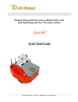
The digital controlled DC motor system is depicted as the following diagram.
G
E
+
Controller
U
DC Motor
F
Potentiometer
In the case of PID control, the transfer function of the PID controller looks like as:
U (s) / E (s) K P K D S K I / S
When using potentiometers (optical encoder and etc.) as the rotational position feedback, you have to
set the motor polarity properly using “WiRobotSDK” ActiveX control API “SetMotorPolarityX“ so
that the negative feedback is achieved. See “SetMotorPolarityX“ for detail.
The control of the standard RC servo motors is carried out by the built-in analog PID controller.
III.2.1. DC Motor Control
75
76
77
78
79
80
81
void SetMotorPolarity1 (short polarity);
void SetMotorPolarity2 (short polarity);
void SetMotorPolarity3 (short polarity);
void SetMotorPolarity4 (short polarity);
void SetMotorPolarity5 (short polarity);
void SetMotorPolarity6 (short polarity);
void SetMotorPolarity (short channel, short polarity);
Description:
SetMotorPolarityX set the motor polarity to 1 or -1 for each motor channel.
1. When the motor is running in positive direction, the potentiometer value is also
increasing; motor polarity should be set to 1 which is default.
2. When the motor is running in positive direction, the potentiometer value is decreasing,
motor polarity should be set to -1 or change the sensor mounting so that the
potentiometer value increases.
Syntax:
Copyright © Dr Robot Inc. 2008
ival = SetMotorPolarity1 (short polarity);
ival = SetMotorPolarity2 (short polarity);
ival = SetMotorPolarity3 (short polarity);
ival = SetMotorPolarity4 (short polarity);
// Motor #1
// Motor #2
// Motor #3
// Motor #4
20
ival = SetMotorPolarity5 (short polarity); // Motor #5
ival = SetMotorPolarity6 (short polarity); // Motor #6
ival = SetMotorPolarity (short channel, short polarity);
// motor#1, 2, 3, 4, 5, or 6
Parameter:
short polarity;
//1 or -1
short channel;
// 0, 1, 2, 3, 4, or 5 for Sonar #1, 2, 3, 4, 5, 6
Return value: void
ival;
82
83
void EnableDcMotor (short channel);
void DisableDcMotor ( short channel);
Description:
These functions are obsolete. Please see function ResumeDcMotor(short channel) and
SuspendDcMotor(short channel).
84
85
void ResumeDcMotor (short channel);
void SuspendDcMotor (short channel);
Description:
ResumeDcMotor resumes the specified DC motor control channel.
SuspendDcMotor suspends the specified DC motor control channel. PWM output is all low.
Syntax:
ResumeDcMotor (channel);
SuspendDcMotor (channel);
Parameter:
short channel;
Return value: void
// 0, 1, 2, 3, 4, or 5
Remarks:
1. All motor control channels are initially suspended when the system boot-up.
86
87
void SetDcMotorPositionControlPID (short channel, short Kp, short Kd, short Ki_x100);
void SetDcMotorVelocityControlPID (short channel, short Kp, short Kd, short Ki_x100);
Description:
SetDcMotorPositionControlPID sets up the PID control parameters of the specified DC
motor channel for position control.
SetDcMotorVelocityControlPID sets up the PID control parameters of the specified DC
motor control channel for velocity.
Syntax:
Copyright © Dr Robot Inc. 2008
SetDcMotorPositionControlPID (channel, KP, KD, KI _x100);
SetDcMotorVelocityControlPID (channel, KP, KD, KI _x100);
21
Parameter:
short channel;
short KP;
short KD;
short KI_x100;
// 0, 1, 2, 3, 4, or 5
// Proportional gain
// Derivative gain
// 100 times KI (the desired Integral gain), when
KI_x100 = 100, the actual integral control term is KI
= 1, KI _x100 with range of 0 ~ 25599
Return value: void
Remarks:
1. When setting KI = 0, that means NO integral control
2. System default value for position control: KP = 50; KD = 5; KI _x100 = 0.
3. System default value for velocity control: KP = 50; KD = 5; KI _x100 = 0.
See Also: SetDcMotorControlMode
88
void SetDcMotorTrajectoryPlan (short channel, short TrajPlanMthod);
Description:
This function is obsolete.
89
void SetDcMotorSensorFilter (short channel, short FilterMethod);
Description:
This filtering feature is still under development. All data will be treated as raw data.
90
void SetDcMotorSensorUsage (short channel, short SensorType);
Description:
SetDcMotorSensorUsage sets the sensor type for the specified DC motor control channel
on the Sensing and Motion Controller (PMS5005). The available sensor types are single
potentiometer, dual potentiometers, and quadrature encoder. The single potentiometer
sensor is for the control of robot joint with limited rotation range (0˚ to 332˚). The dual
potentiometers and the quadrature sensor are for continuous rotating joint (like wheels)
control.
Syntax:
SetDcMotorSensorUsage (channel, SensorType)
Parameter:
short channel;
short SensorType;
Copyright © Dr Robot Inc. 2008
// 0, 1, 2, 3, 4, or 5 for single potentiometer sensor
// 0, 1, or 2 for dual potentiometer sensor
// 0 or 1 for quadrature encoder
// 0 -- Single potentiometer sensor
// 1 -- Dual potentiometer sensor
22
// 2 – Quadrature encoder
Return value: void
Remarks:
1. The electrical angular range of the potentiometer position sensor is 0˚ to 332˚ and
the corresponding mechanical rotation range is 14˚ to 346˚, when the 180
position is defined at sensor’s physical middle position.
2. Each DC motor channel for dual potentiometer sensor utilizes two potentiometer
channels. DC motor channel 0 will use potentiometer channel 0 and 5; DC motor
channel 1 will use potentiometer channel 1 and 4; DC motor channel 2 will use
potentiometer channel 2 and 3. Please refer to the relevant application note for
the use of dual potentiometers.
3. Quadrature encoder will only use DC motor channel 0 and 1.
4. System’s default setting for sensor usage is single potentiometer.
See also: GetSensorPot
91
void SetDcMotorControlMode (short channel, short controlMode);
Description:
SetDcMotorControlMode sets the control mode of the specified DC motor control channel
on the Sensing and Motion Controller (PMS5005). The available control modes are openloop PWM control, closed-loop position control, closed-loop velocity control.
Syntax:
SetDcMotorControlMode (channel, controlMode)
Parameter:
short channel;
short controlMode;
// 0, 1, 2, 3, 4, or 5
// 0 – Open-loop PWM Control
// 1 – Closed-loop Position Control
// 2 – Closed-loop Velocity Control
Return value: void
Remarks:
System’s default setting for control mode is Open-loop PWM Control.
See also: SetDcMotorPositionControlPID, SetDcMotorVelocityControlPID
92
void DcMotorPositionTimeCtr (short channel, short cmdValue, short timePeriod);
Description:
DcMotorPositionTimeCtr sends the position control command to the specified motion
control channel on the Sensing and Motion Controller (PMS5005). The command includes
the target position and the target time period to execute the command. The current
trajectory planning method with time control is linear.
Copyright © Dr Robot Inc. 2008
23
Syntax:
DcMotorPositionTimeCtr (channel, cmdValue, timePeriod);
Parameter:
short channel;
short cmdValue;
short timePeriod;
Return value: void
// 0, 1, 2, 3, 4, or 5
// Target position value
// Executing time in milliseconds
Remarks:
1. Motor will be enabled automatically by the system when this command is received.
2. Target position value is in the A/D sampling data range 0 to 4095 when using
single potentiometer, 0-4428 when using dual potentiometers.
3. Please refer to the description of GetSensorPot for data converting between
angular values and the A/D sampling data values.
4. When using encoder as sensor input, the target position value is the pulse count in
the range of 0- 32767.
See also: GetSensorPot
93
void DcMotorPositionNonTimeCtr(short channel, short cmdValue);
Description:
DcMotorPositionNonTimeCtr sends the position control command to the specified motion
control channel on the Sensing and Motion Controller (PMS5005). The command includes
the target position but no time period specified to execute the command. The motion
controller will drive the motor to the target position at the maximum speed.
Syntax:
Parameter:
DcMotorPositionNonTimeCtr (channel, cmdValue);
short channel;
short cmdValue;
Return value: void
// 0, 1, 2, 3, 4, or 5
// Target position value
Remarks:
1. Motor will be enabled automatically by the system when this command is received.
2. Target position value is in the A/D sampling data range 0 to 4095 when using
single potentiometer, 0-4428 when using dual potentiometers.
3. Please refer to the description of GetSensorPot for data converting between
angular values and the A/D sampling data values.
4. When using encoder as sensor input, the target position value is the pulse count in
the range of 0- 32767.
See also: DcMotorPositionTimeCtr, GetSensorPot
Copyright © Dr Robot Inc. 2008
24
94
void DcMotorVelocityTimeCtr(short channel, short cmdValue, short timePeriods);
Description:
DcMotorVelocityTimeCtr sends the velocity control command to the specified motion
control channel on the Sensing and Motion Controller (PMS5005). The command includes
the target velocity and the time period to execute the command. The current trajectory
planning method for time control is linear.
Syntax:
DcMotorVelocityTimeCtr (channel, cmdValue, timePeriod);
Parameter:
short channel;
short cmdValue;
short timePeriod;
Return value: void
// 0, 1, 2, 3, 4, or 5
// Target velocity value
// Executing time in milliseconds
Remarks:
1. Motor will be enabled automatically by the system when this command is received
2. No velocity is available for motor channel using single potentiometer sensor
3. The unit of the velocity is (Position change in A/D sampling data) / second when
using dual potentiometer sensor for rotational position measurement and pulse/
second when using quadrature encoder.
4. Please refer to the description of GetSensorPot for data conversion between
angular values and the A/D sampling data values.
See also: GetSensorPot
95
void DcMotorVelocityNonTimeCtr(short channel, short cmdValue);
Description:
DcMotorVelocityNonTimeCtr sends the velocity control command to the specified motion
control channel on the Sensing and Motion Controller (PMS5005). The command includes
the target velocity but no time period specified to execute the command. The motion
controller will drive the motor to achieve the target velocity with maximum effort.
Syntax:
Parameter:
DcMotorVelocityNonTimeCtr (channel, cmdValue);
short channel;
short cmdValue;
Return value: void
// 0, 1, 2, 3, 4, or 5
// Target velocity value
Remarks:
1. Motor will be enabled automatically by the system when this command is received
2. No velocity is available for motor channel using single potentiometer sensor
Copyright © Dr Robot Inc. 2008
25
3. The unit of the velocity is (Position change in A/D sampling data) / second when
using dual potentiometer sensor for rotational position measurement and pulse/
second when using quadrature encoder.
4. Please refer to the description of GetSensorPot for data conversion between
angular values and the A/D sampling data values.
See also: DcMotorVelocityTimeCtr, GetSensorPot
96
void DcMotorPwmTimeCtr(short channel, short cmdValue, short timePeriod);
Description:
DcMotorPwmTimeCtr sends the PWM control command to the specified motion control
channel on the Sensing and Motion Controller (PMS5005). The command includes the
target pulse width value and the time period to execute the command. The current
trajectory planning method for time control is linear.
Syntax:
DcMotorPwmTimeCtr (channel, cmdValue, timePeriod);
Parameter:
short channel;
short cmdValue;
short timePeriod;
Return value: void
// 0, 1, 2, 3, 4, or 5
// Target pulse width value
// Executing time in milliseconds
Remarks:
1. The specified channel (motor) will be enabled automatically by the system when
this command is received
2. Target pulse width value range is 0 to 32767 (0x7FFF), corresponding to the duty
cycle of 0 to 100% linearly.
3. A pulse width value of 16383 means 50% duty cycle, putting motor in “Stop” stage.
Any value in between 16384 - 32767 will put the motor to turn clockwise (facing
the front side of the motor) and any value in between 0 – 16362 will put the motor
to turn counter-clockwise.
97
void DcMotorPwmNonTimeCtr(short channel, short cmdValue);
Description:
DcMotorPwmNonTimeCtr sends the PWM control command to the specified motion
control channel on the Sensing and Motion Controller (PMS5005). The command includes
the target pulse width value without specific execution time period. The motion controller
will set the PWM output of this channel to the target value immediately.
Syntax:
DcMotorPwmNonTimeCtr (channel, cmdValue);
Parameter:
short channel;
short cmdValue;
Copyright © Dr Robot Inc. 2008
// 0, 1, 2, 3, 4, or 5
// Target pulse width value
26
Return value: void
Remarks:
1. The specified channel (motor) will be enabled automatically by the system when
this command is received
2. Target pulse width value range is 0 to 32767 (0x7FFF), corresponding to the duty
cycle of 0 to 100% linearly.
3. A pulse width value of 16383 means 50% duty cycle, putting motor in “Stop” stage.
Any value in between 16384 - 32767 will put the motor to turn clockwise (facing
the front side of the motor) and any value in between 0 – 16362 will put the motor
to turn counter-clockwise.
See also: DcMotorPwmTimeCtr
98
void DcMotorPositionTimeCtrAll(short cmd1, short cmd2, short cmd3, short cmd4,
short cmd5, short cmd6, short timePeriod);
Description:
DcMotorPositionTimeCtrAll sends the position control command to all 6 DC motor control
channels on the sensing and motion controller (PMS5005) at the same time. The command
includes the target positions and the time period to execute the command. The current
trajectory planning method for time control is linear.
Syntax:
Parameter:
DcMotorPositionTimeCtrAll (cmd1, cmd2, cmd3, cmd4, cmd5, cmd6,
timePeriod);
short cmd1;
short cmd2;
short cmd3;
short cmd4;
short cmd5;
short cmd6;
short timePeriod;
Return value: void
// Target position for channel #1
// Target position for channel #2
// Target position for channel #3
// Target position for channel #4
// Target position for channel #5
// Target position for channel #6
// Executing time in milliseconds
Remarks:
1. All DC Motors will be enabled automatically by the system when this command is
received.
2. Target position value is in the A/D sampling data range 0 to 4095 when using
single potentiometer, 0-4428 when using dual potentiometers.
3. Please refer to the description of GetSensorPot for data converting between
angular values and the A/D sampling data values.
4. When using encoder as sensor input, the target position value is the pulse count in
the range of 0- 32767.
5. When some motors are not under controlled, their command values should be set
as -32768 (0x8000). That means NO_CONTROL.
Copyright © Dr Robot Inc. 2008
27
See also: DcMotorPositionTimeCtr,
99
void DcMotorPositionNonTimeCtrAll(short cmd1, short cmd2, short cmd3,
short cmd4, short cmd5, short cmd6);
Description:
DcMotorPositionNonTimeCtrAll sends the position control command to all 6 DC motor
control channels on the Sensing and Motion Controller (PMS5005) at the same time. The
command includes the target positions without specific execution time period. The motion
controller will drive the motor to reach the target position with maximum effort.
Syntax:
Parameter:
DcMotorPositionNonTimeCtrAll(cmd1, cmd2, cmd3, cmd4, cmd5, cmd6);
short cmd1;
short cmd2;
short cmd3;
short cmd4;
short cmd5;
short cmd6;
Return value: void
// Target position for channel #1
// Target position for channel #2
// Target position for channel #3
// Target position for channel #4
// Target position for channel #5
// Target position for channel #6
Remarks:
1. All DC motors will be enabled automatically by the system when this command is
received.
2. Target position value is in the A/D sampling data range 0 to 4095 when using
single potentiometer, 0-4428 when using dual potentiometers.
3. Please refer to the description of GetSensorPot for data converting between
angular values and the A/D sampling data values.
4. When using encoder as sensor input, the target position value is the pulse count in
the range of 0- 32767.
5. When some motors are not under controlled, their command values should be set
as -32768 (0x8000). That means NO_CONTROL.
See also: DcMotorPositionNonTimeCtr
100 void DcMotorVelocityTimeCtrAll(short cmd1, short cmd2, short cmd3, short cmd4,
short cmd5, short cmd6, short timePeriods);
Description:
DcMotorVelocityTimeCtrAll sends the velocity control command to all 6 DC motor control
channels on the Sensing and Motion Controller (PMS5005) at the same time. The
command includes the target velocities and the time period to execute the command. The
trajectory planning method for time control is linear.
Copyright © Dr Robot Inc. 2008
28
Syntax:
DcMotorVelocityTimeCtrAll (cmd1, cmd2, cmd3, cmd4, cmd5, cmd6,
timePeriods);
Parameter:
short cmd1;
short cmd2;
short cmd3;
short cmd4;
short cmd5;
short cmd6;
short timePeriod;
Return value: void
// Target velocity for channel #1
// Target velocity for channel #2
// Target velocity for channel #3
// Target velocity for channel #4
// Target velocity for channel #5
// Target velocity for channel #6
// Executing time in milliseconds
Remarks:
1. Motor will be enabled automatically by the system when this command is received
2. No velocity is available for motor channel using single potentiometer sensor
3. The unit of the velocity is (Position change in A/D sampling data) / second when
using dual potentiometer sensor for rotational position measurement and pulse/
second when using quadrature encoder.
4. Please refer to the description of GetSensorPot for data conversion between
angular values and the A/D sampling data values.
5. When some motors are not under controlled, their command values should be set
as -32768 (0x8000). That means NO_CONTROL.
See also: DcMotorVelocityTimeCtr
101 void DcMotorVelocityNonTimeCtrAll(short cmd1, short cmd2, short cmd3,
short cmd4, short cmd5, short cmd6);
Description:
DcMotorVelocityNonTimeCtrAll sends the velocity control command to all 6 DC motor
control channels on the Sensing and Motion Controller (PMS5005) at the same time. The
command includes the target velocities without specific execution time period. The motion
controller will drive the motor to achieve the target velocity with maximum effort.
Syntax:
Parameter:
DcMotorVelocityNonTimeCtrAll (cmd1, cmd2, cmd3, cmd4, cmd5, cmd6);
short cmd1;
short cmd2;
short cmd3;
short cmd4;
short cmd5;
short cmd6;
Return value: void
Copyright © Dr Robot Inc. 2008
// Target velocity for channel #1
// Target velocity for channel #2
// Target velocity for channel #3
// Target velocity for channel #4
// Target velocity for channel #5
// Target velocity for channel #6
29
Remarks:
1. Motor will be enabled automatically by the system when this command is received
2. No velocity is available for motor channel using single potentiometer sensor
3. The unit of the velocity is (Position change in A/D sampling data) / second when
using dual potentiometer sensor for rotational position measurement and pulse/
second when using quadrature encoder.
4. Please refer to the description of GetSensorPot for data conversion between
angular values and the A/D sampling data values.
5. When some motors are not under controlled, their command values should be set
as -32768 (0x8000). That means NO_CONTROL.
See also: DcMotorVelocityNonTimeCtr
102 void DcMotorPwmTimeCtrAll(short cmd1, short cmd2, short cmd3, short cmd4,
short cmd5, short cmd6, short timePeriods);
Description:
DcMotorPwmTimeCtrAll sends the PWM control command to all 6 DC motor control
channels on the Sensing and Motion Controller (PMS5005) at the same time. The
command includes the target PWM values and the time period to execute the command.
The current trajectory planning method for time control is linear.
Syntax:
DcMotorPwmTimeCtrAll (cmd1, cmd2, cmd3, cmd4, cmd5, cmd6,
timePeriods);
Parameter:
short cmd1;
short cmd2;
short cmd3;
short cmd4;
short cmd5;
short cmd6;
short timePeriod;
Return value: void
// Target PWM value for channel #1
// Target PWM value for channel #2
// Target PWM value for channel #3
// Target PWM value for channel #4
// Target PWM value for channel #5
// Target PWM value for channel #6
// Executing time in milliseconds
Remarks:
1. All channel (motors) will be enabled automatically by the system when this
command is received
2. Target pulse width value range is 0 to 32767 (0x7FFF), corresponding to the duty
cycle of 0 to 100% linearly.
3. A pulse width value of 16383 means 50% duty cycle, putting motor in “Stop” stage.
Any value in between 16384 - 32767 will put the motor to turn clockwise (facing
the front side of the motor) and any value in between 0 – 16362 will put the motor
to turn counter-clockwise.
4. When some motors are not under controlled, their command values should be set
as -32768 (0x8000). That means NO_CONTROL.
See also: DcMotorPwmTimeCtr
Copyright © Dr Robot Inc. 2008
30
103 void DcMotorPwmNonTimeCtrAll(short cmd1, short cmd2, short cmd3, short cmd4,
short cmd5, short cmd6);
Description:
DcMotorPwmNonTimeCtrAll sends the PWM control command to all 6 DC motor control
channels on the Sensing and Motion Controller (PMS5005) at the same time. The
command includes the target PWM values without specific execution time period. The
motion controller Send the desired PWM pulse width right away.
Syntax:
DcMotorPwmNonTimeCtrAll (cmd1, cmd2, cmd3, cmd4, cmd5, cmd6);
Parameter:
short cmd1;
short cmd2;
short cmd3;
short cmd4;
short cmd5;
short cmd6;
Return value: void
// Target PWM value for channel #1
// Target PWM value for channel #2
// Target PWM value for channel #3
// Target PWM value for channel #4
// Target PWM value for channel #5
// Target PWM value for channel #6
Remarks:
1. All channel (motors) will be enabled automatically by the system when this
command is received
2. Target pulse width value range is 0 to 32767 (0x7FFF), corresponding to the duty
cycle of 0 to 100% linearly.
3. A pulse width value of 16383 means 50% duty cycle, putting motor in “Stop” stage.
Any value in between 16384 - 32767 will put the motor to turn clockwise (facing
the front side of the motor) and any value in between 0 – 16362 will put the motor
to turn counter-clockwise.
4. When some motors are not under controlled, their command values should be set
as -32768 (0x8000). That means NO_CONTROL.
See also: DcMotorPwmNonTimeCtr
III.2.2. RC Servo Motor Control
104 void EnableServo (short channel);
105 void DisableServo (short channel);
Description:
EnableServo enables the specified servo motor control channel.
DisableServo disables the specified servo motor control channel.
Syntax:
Copyright © Dr Robot Inc. 2008
EnableServo (channel);
DisableServo (channel);
31
Parameter:
short channel;
Return value: void
// 0, 1, 2, 3, 4, or 5
Remarks:
All servo motor channels are disabled initially at system startup. They need to be enabled
explicitly before use.
106 void SetServoTrajectoryPlan(short channel, short TrajPlanMthod);
Description:
This function is obsolete.
107 void ServoTimeCtr(short channel, short cmdValue, short timePeriods);
Description:
ServoTimeCtr sends the position control command to the specified servo motor control
channel on the Sensing and Motion Controller (PMS5005). The command includes the
target position command and the time period to execute the command. The current
trajectory planning method for time control is linear.
Syntax:
Parameter;
ServoTimeCtr (channel, cmdValue, timePeriod);
short channel;
short cmdValue;
short timePeriod;
Return value: void
// 0, 1, 2, 3, 4, or 5
// Target Pulse Width (ms) * 2250
// Executing time in milliseconds
Remarks:
1. Target position value for cmdValue = (Pulse width in millisecond) * 2250.
2. Usually, a standard remote control servo motor expects to get the specified pulse
width in every 20 milliseconds in order to hold the corresponding angle position.
The pulse width value in millisecond for 0˚, 90˚ and 180˚ are servo manufacturer
and model dependant, they are around 1ms, 1.5ms and 2.0ms respectively for most
common servos. Experiments are required to obtain the exact value which varies
for different servo motors.
108 void ServoNonTimeCtr(short channel, short cmdValue);
Description:
ServoNonTimeCtr sends the position control command to the specified servo motor
control channel on the Sensing and Motion Controller (PMS5005). The command includes
the target position command without specific execution time period. The motion controller
will send the desired pulse width to the servo motor right away.
Copyright © Dr Robot Inc. 2008
32
Syntax:
ServoNonTimeCtr (channel, cmdValue);
Parameter:
short channel;
short cmdValue;
Return value: void
// 0, 1, 2, 3, 4, or 5
// Target Pulse Width (ms) * 2250
Remarks:
Please refer to the remarks under ServoTimeCtr.
See also: ServoTimeCtr
109 void ServoTimeCtrAll(short cmd1, short cmd2, short cmd3, short cmd4,
short cmd5, short cmd6, short timePeriod);
Description:
ServoTimeCtrAll sends the position control command to all 6 servo motor control channels
on the Sensing and Motion Controller (PMS5005) at the same time. The command includes
the target position commands and the time period to execute the command. The current
trajectory planning method for time control is linear.
Syntax:
ServoTimeCtrAll (cmd1, cmd2, cmd3, cmd4, cmd5, cmd6, timePeriod);
Parameter:
short cmd1;
short cmd2;
short cmd3;
short cmd4;
short cmd5;
short cmd6;
short timePeriod;
Return value: void
// Target position for channel #1
// Target position for channel #2
// Target position for channel #3
// Target position for channel #4
// Target position for channel #5
// Target position for channel #6
// Executing time in milliseconds
Remarks:
1. Please refer to the remarks under ServoTimeCtr.
2. When some servo motors are not under controlled, their command values should be
set as -32768 (0x8000). That means NO_CONTROL.
See also: ServoTimeCtr
110 void ServoNonTimeCtrAll (short cmd1, short cmd2, short cmd3, short cmd4,
short cmd5, short cmd6);
Description:
Copyright © Dr Robot Inc. 2008
33
ServoNonTimeCtrAll sends the position control command to all 6 servo motor control
channels on the Sensing and Motion Controller (PMS5005) at the same time. The command
includes the target position commands without specific execution time period. The motion
controller send the desired pulse width to the servo motor right away.
Syntax:
ServoNonTimeCtrAll(cmd1, cmd2, cmd3, cmd4, cmd5, cmd6);
Parameter:
short cmd1;
short cmd2;
short cmd3;
short cmd4;
short cmd5;
short cmd6;
void
Return value:
// Target position for channel #1
// Target position for channel #2
// Target position for channel #3
// Target position for channel #4
// Target position for channel #5
// Target position for channel #6
Remarks:
1. Please refer to the remarks under ServoTimeCtr
2. When some motors are not under controlled, their command values should be set
as -32768 (0x8000). That means NO_CONTROL.
See Also: ServoTimeCtr
III.3.
Multimedia Control
III.3.1. LCD Display
111
void LcdDisplayPMS(LPCTSTR bmpFileName);
Description:
LcdDisplayPMS displays the image data in the file bmpFileName (BMP format) on the
graphic LCD connected to the Sensing and Motion Controller (PMS5005).
Syntax:
LcdDisplayPMS (bmpFileName);
Parameter:
LPCTSTR bmpFileName;
Return value: void
// Full path of the BMP file for displaying
Remarks:
The graphic LCD display is mono with dimension of 128 pixels by 64 pixels. The bmp image
must be 128x64 pixels in mono.
III.4.
Events
Copyright © Dr Robot Inc. 2008
34
This section documents the four Event mechanisms. When the relevant data arrive from the WiRobot
PMS5005 system, relevant event will be fired, user could write his / her periodic data processing
routine in the relevant event call back function.
112 StandardSensorEvent
Description:
When the standard sensor data arrive, this event will be triggered.
113 CustomSensorEvent
Description:
When the custom expansion sensor (AD and Input) data arrive, this event will be triggered.
114 MotorSensorEvent
Description:
When the motor control related sensor data arrive, this event will be triggered. The motor
control data includes all the motor rotational sensor data such as potentiometer, encoder
and motor current data.
Copyright © Dr Robot Inc. 2008
35
IV.
WiRobot SDK API Reference for PMB5010
WiRobot SDK APIs for PMB5010 supports advanced Multimedia Control features.
IV.1.
Multimedia Control
This section contains the APIs for the operations of audio input and output, image capturing and LCD
display.
IV.1.1.
Audio Input and Output
115 void PlayAudioFile(LPCTSTR fileName);
Description:
PlayAudioFile sends an audio file (.wav format) to the Multimedia Controller (PMB5010).
The file will be played back on the speaker.
Syntax:
PlayAudioFile (FileName);
Parameter:
LPCTSTR FileName;
Return value: void
//the file name with full path
Remarks:
The .wav audio file should contain 16-bit sound wave data sampled at 8 kHz with PCM raw
data format using mono channel. Other supplied wave file format will still be played by the
robot but may have undesired result.
116 void StopAudioPlay ();
Description:
StopAudioPlay stops a playing audio on the Multimedia Controller (PMB5010).
Syntax:
StopAudioPlay ();
Return value: void
Remarks:
There will be no effect if no audio is playing.
117 long GetVoiceSegment();
Description:
GetVoiceSegment returns the pointer to current voice data (recorded from robot
microphone) in memory.
Syntax:
Copyright © Dr Robot Inc. 2008
lpVal = GetVoiceSegment();
36
Parameter:
void
Return value: long lpVal;
// pointer to current voice data.
Remark:
(1) You should use method GetVoiceSegLength() to get the length of the Voice
segment.
(2) Voice data is in PCM raw data format with 16bit, 8KHz sampling rate.
118 long GetVoiceSegLength();
Description:
GetVoiceSegLength returns the length of current voice data in memory.
Syntax:
voiceLength = GetVoiceSegLength ();
Parameter:
void
Return value: long voiceLength;
// Length of current voice data.
See Also: GetVoiceSegment
119 void StartRecord(short voiceSegment);
Description:
StartRecord sends start-recording command to the Multimedia Controller (PMB5010).
The recorded voice data in length specified by voiceSegment will be stored in the shared
memory segment.
Syntax:
StartRecord(voiceSegment);
Parameter:
short voiceSegment;
Return value: void
// segment number for voice data, range 1 -10
Remarks:
The parameter voiceSegment specify the time of voice segment, unit is 256 millisecond
(about 1/4 sec). Value could be 1- 10. For example, if voiceSegment is 4, 1.024 second
voice will be recorded. VoiceSegmentEvent event will fired when the data is ready.
120 void StopRecord();
Description:
Copyright © Dr Robot Inc. 2008
37
StopRecord sends stop-recording command to the Multimedia Controller (PMB5010).
SDK will not send recorded voice data to PC any more.
Syntax:
StopRecord();
Parameter:
void
Return value: void
Remarks:
There will be no effect if the Multimedia Controller is not recording.
IV.1.2. Image Capturing
121 void TakePhoto();
Description:
TakePhoto sends image capturing command to the Multimedia Controller (PMB5010).
The Multimedia Controller will send back the latest frame of the image data to the WiRobot
shared memory after receiving TakePhoto command. Use SavePhotoAsBMP to obtain the
image.
Syntax:
TakePhoto();
Parameter:
void
Return value: void
Remarks:
Each TakePhoto command will get one frame of image.
122 BOOL SavePhotoAsBMP(LPCTSTR FileName);
Description:
SavePhotoAsBMP saves current frame of image data into BMP format file FileName.
Syntax:
bVal = SavePhotoAsBMP (FileName);
Parameter:
LPCTSTR FileName;
Return value: BOOL bVal;
// the file name with full path, for saving image
data in bmp format.
// True: success
// False: failure to save.
Remarks:
1. Before calling SavePhotoAsBMP, the TakePhoto command needs to be called to
request image taken.
Copyright © Dr Robot Inc. 2008
38
2. When the image data arrive, the call back event “ImageEvent” will be fired
3. The cause of “failure to save” could be caused because the TakePhoto command
was not sent or the file name / path is invalid.
IV.1.3. LCD Display
123 void LcdDisplayPMB(LPCTSTR bmpFileName);
Description:
LcdDisplayPMB displays the image data in the file bmpFileName (BMP format) on the
graphic LCD connected to the Multimedia Controller (PMB5010).
Syntax:
LcdDisplayPMB (bmpFileName);
Parameter:
LPCTSTR bmpFileName; // Full path of the BMP file for displaying
Return value: void
Remarks:
The graphic LCD display is mono with dimension of 128 pixels by 64 pixels. The bmp image
must be 128x64 pixels in mono.
IV.2.
Events
This section documents the two Event mechanisms. When the relevant data arrive from the WiRobot
PMB5010 system, relevant event will be fired, user could write his / her periodic data processing
routine in the relevant event call back function.
124 ImageEvent
Description:
When the image data arrive, this event will be triggered.
125 VoiceSegmentEvent
Description:
When the audio data arrive, this event will be triggered.
Copyright © Dr Robot Inc. 2008
39
V.
V.1.
Power Controller API
short GetVolRef( )
Description:
GetVolRef returns the power controller AD reference voltage (AD value)
Syntax:
ival = GetVolRef ();
Parameter:
void
Return value:
short ival
Remarks;
The AD reference Voltage
Vref = ((ival / 4095) * 3.0 ) * 2
V.2.
short GetBat1Vol( )
Description:
GetBat1Vol returns the battery1 voltage (AD value)
Syntax:
ival = GetBat1Vol ();
Parameter:
void
Return value:
short ival
Remarks:
The Battery1 voltage
VBat1 = (ival /4095 *Vref ) * 8
V.3.
short GetBat1Temp( )
Description:
GetBat1Temp returns the battery1 temperature sensor (AD value)
Syntax:
ival = GetBat1Temp ();
Parameter:
void
Return value:
short ival
The value must be in the range of 1100 – 2500, if beyond this range, stop charging the
battery
V.4.
short GetBat2Vol( )
Description:
GetBat2Vol returns the battery2 voltage (AD value)
Syntax:
ival = GetBat2Vol ();
Parameter:
void
Return value:
short ival
Remarks:
The Battery2 voltage
VBat2 = (ival /4095 *Vref ) * 8
Copyright © Dr Robot Inc. 2008
40
V.5.
short GetBat2Temp( )
Description:
GetBat2Temp returns the battery2 temperature sensor (AD value)
Syntax:
ival = GetBat2Temp ();
Parameter:
void
Return value:
short ival
The value must be in the range of 1100 – 2500, if beyond this range, stop charging the
battery
V.6.
short GetDCINVol()
Description:
GetDCINVol returns the DCIN voltage (AD value)
Syntax:
ival = GetDCINVol ();
Parameter:
void
Return value:
short ival
Remarks:
The DCIN voltage
VBat2 = (ival /4095 *Vref ) * 8
V.7.
byte GetCHGPath( )
Description:
GetCHGPath returns the charge path
Syntax:
ival = GetCHGPath ();
Parameter:
void
Return value:
Byte ival
Bit
Description
0
X
1
X
2
X
3
X
4
X
5
X
6
Charge Battery 2
7
Charge Battery 1
V.8.
byte GetPowerPath( )
Description:
GetPowerPath returns the power path of controller
Syntax:
ival = GetPowerPath ();
Copyright © Dr Robot Inc. 2008
41
Parameter:
Return value:
Bit
0
1
2
3
4
5
6
7
V.9.
ival
Description
X
X
X
X
X
Power by DCIN
Power by Battery 2
Power by Battery 1
byte GetCHGStatus( )
Description:
GetCHGStatus
Syntax:
Parameter:
Return value:
Bit
0
1
2 - CH
3 – PF
4 -DC
5 – LP
6—FA
7
V.10.
void
Byte
returns the status of power controller.
ival = GetCHGStatus ();
void
Byte ival
Description
X
X
1 -- Charging 0 – no charge
Power fail
DCDIV comparator output
Lower power
Fault(on reset, short circuit, shut down by DCDIV
X
void SendCmdCHG( )
Description:
SendCmdCHG sends the command to power controller.
Syntax:
void SendCmdCHG (byte ival);
Parameter:
byte ival
Return value:
void
Bit
0
1
2
3
Copyright © Dr Robot Inc. 2008
Description
Reset WIFI1 – power 0 – reset 200ms
Reset TI 1 – power 0 – reset 200ms
Motor805 power 1—power 0 – turn off
Power by DCIN
42
4
5
6
7
Copyright © Dr Robot Inc. 2008
Power by Bat2
Power by Bat1
Charge Bat2 1 – charge 0 – stop charge
Charge Bat1 1—charge 0 – stop charge
43
VI.
VI.1.
Constellation system API
short GetGPS01( )
Description:
Get the distance measurement (unit: mm) from the LEFT Constellation receiver
module on the car to the selected Constellation transponder (ID = ID1).
Syntax:
ival = GetGPS01 ( );
Parameter:
void
Return value:
short ival
Remarks:
If ival = 0x7fff, it means receiver did not get the distance measurement, the
transponder with ID1 is out of range.
If ival = 0x7ff0, it means receiver did not get any new distance data.
VI.2.
short GetGPS02 ( )
Description:
Get the distance measurement (unit: mm) from the LEFT Constellation receiver on
the car to the selected Constellation transponder (ID = ID2).
Syntax:
ival = GetGPS02 ( );
Parameter:
void
Return value:
short ival
Remarks:
If ival = 0x7fff, it means receiver did not get the distance measurement, the
transponder with ID2 is out of range.
If ival = 0x7ff0, it means receiver did not get any new distance data.
VI.3.
short GetGPS03 ( )
Description:
Get the distance measurement (unit: mm) from the LEFT Constellation receiver on
the car to the selected Constellation transponder (ID = ID3).
Syntax:
ival = GetGPS03 ( );
Parameter:
void
Return value:
short ival
Remarks:
If ival = 0x7fff, it means receiver did not get the distance measurement, the
transponder with ID3 is out of range.
If ival = 0x7ff0, it means receiver did not get any new distance data.
VI.4.
short GetGPS04 ( )
Description:
Get the distance measurement (unit: mm) from the LEFT Constellation receiver on
the car to the selected Constellation transponder (ID = ID4).
Syntax:
ival = GetGPS04 ( );
Copyright © Dr Robot Inc. 2008
44
Parameter:
void
Return value:
short ival
Remarks:
If ival = 0x7fff, it means receiver did not get the distance measurement, the
transponder with ID4 is out of range.
If ival = 0x7ff0, it means receiver did not get any new distance data.
VI.5.
short GetGPS05 ( )
Description:
Get the distance measurement (unit: mm) from the RIGHT Constellation receiver on
the car to the selected Constellation transponder (ID = ID1).
Syntax:
ival = GetGPS05 ( );
Parameter:
void
Return value:
short ival
Remarks:
If ival = 0x7fff, it means receiver did not get the distance measurement, the
transponder with ID1 is out of range.
If ival = 0x7ff0, it means receiver did not get any new distance data.
VI.6.
short GetGPS06 ( )
Description:
Get the distance measurement (unit: mm) from the RIGHT Constellation receiver on
the car to the selected Constellation transponder (ID = ID2).
Syntax:
ival = GetGPS06 ( );
Parameter:
void
Return value:
short ival
Remarks:
If ival = 0x7fff, it means receiver did not get the distance measurement, the
transponder with ID2 is out of range.
If ival = 0x7ff0, it means receiver did not get any new distance data.
VI.7.
short GetGPS07 ( )
Description:
Get the distance measurement (unit: mm) from the RIGHT Constellation receiver on
the car to the selected Constellation transponder (ID = ID3).
Syntax:
ival = GetGPS07 ( );
Parameter:
void
Return value:
short ival
Remarks:
If ival = 0x7fff, it means receiver did not get the distance measurement, the
transponder with ID3 is out of range.
If ival = 0x7ff0, it means receiver did not get any new distance data.
VI.8.
short GetGPS08 ( )
Description:
Copyright © Dr Robot Inc. 2008
45
Get the distance measurement (unit: mm) from the RIGHT Constellation receiver on
the car to the selected Constellation transponder (ID = ID4).
Syntax:
ival = GetGPS08 ( );
Parameter:
void
Return value:
short ival
Remarks:
If ival = 0x7fff, it means receiver did not get the distance measurement, the
transponder with ID4 is out of range.
If ival = 0x7ff0, it means receiver did not get any new distance data.
VI.9.
void setGPSID(Byte id1, Byte id2, Byte id3, Byte id4)
Description:
Set the ID of Constellation transponder that the robot will be using.
Syntax:
void setGPSID(Byte id1, Byte id2, Byte id3, Byte id4)
Parameter:
Byte id1, Byte id2, Byte id3, Byte id4
Return value:
void
Remarks:
The sensor with id1, id2 is on the one Constellation transponder, and the sensor
with id3,id4 is on another transponder.
VI.10. byte getSenID1 ( )
Description:
Get the ID of Constellation transponder that the robot is using. The distance
measurement that is obtained with getGPS01( ) function is from the LEFT receiver module,
and distance measurement that is obtained with getGPS05( ) function is from the RIGHT
receiver module.
Syntax:
ival = getSenID1( )
Parameter:
void
Return value:
byte ival
VI.11. byte getSenID2 ( )
Description:
Get the ID of Constellation transponder that the robot is using. The distance
measurement that is obtained with getGPS02( ) function is from the LEFT receiver module,
and distance measurement that is obtained with getGPS06( ) function is from the RIGHT
receiver module.
Syntax:
ival = getSenID2( )
Parameter:
void
Return value:
byte ival
VI.12. byte getSenID3 ( )
Description:
Copyright © Dr Robot Inc. 2008
46
Get the ID of Constellation transponder that the robot is using. The distance
measurement that is obtained with getGPS03( ) function is from the LEFT receiver module,
and distance measurement that is obtained with getGPS07( ) function is from the RIGHT
receiver module.
Syntax:
ival = getSenID3( )
Parameter:
void
Return value:
byte ival
VI.13. byte getSenID4 ( )
Description:
Get the ID of Constellation transponder that the robot is using. The distance
measurement that is obtained with getGPS04( ) function is from the LEFT receiver module,
and distance measurement that is obtained with getGPS08( ) function is from the RIGHT
receiver module.
Syntax:
ival = getSenID4( )
Parameter:
void
Return value:
byte ival
VI.14. Example of using the Constellation system
Here is the example for calculation the robot position based on the distance measurement
from the Constellation system.
Step 1:
Set the transponder ID to 1,2,3,4:
setGPSID(1,2,3,4);
Step 2:
Get the distance in the custom sensor event.
//First the program should confirm the transponder ID is right.
ID1 = getSneID1( );
ID2 = getSneID2( );
ID3 = getSneID3( );
ID4 = getSneID4( );
//then get the distance unit :mm
If ( ID1 = 1 ) and ( ID2 = 2 ) or ( ID3 = 3 ) or ( ID4 = 4 ) {
//get distance here
Dis_ID1_L = getGPS01 ( );
Dis_ID2_L = getGPS02 ( );
Dis_ID3_L = getGPS03 ( );
Dis_ID4_L = getGPS04 ( );
Dis_ID1_R = getGPS05 ( );
Copyright © Dr Robot Inc. 2008
47
Dis_ID2_R = getGPS06 ( );
Dis_ID3_R = getGPS07 ( );
Dis_ID4_R = getGPS08 ( );
}
Step 3:
Calculate the position based on the information of distance measurement.
Here is the example for transponder 1( with sensor ID = 1, sensor ID = 2)
Sensor ID1 position (X1,Y1,Z1);
Sensor ID2 position (X2,Y2,Z2);
CarHeight = 225;
//unit: mm the height of Constellation receiver on the robot
CarSensorDis = 300; // unit: mm the distance between the left receiver and right
// receiver on the robot
DisSensor = sqr( (X1- X2) ^ 2 + (Y1 – Y2 ) ^ 2); //the distance between two
//sensors on the transponder
L1 = Dis_ID1_L , L2 = Dis_ID2_L. L3 = Dis_ID1_R, L4 = Dis_ID2_R.
All the data must meet the following conditions
1.
2.
3.
4.
abs(L1 –L2) < DisSensor
and abs(L1+L2) > DisSensor
abs(L3 –L4) < DisSensor
and abs(L3+L4) > DisSensor
abs(L1 – L3) < CarSensorDis
and abs(L1+ L3) > CarSensorDis
abs(L2- L4) < CarSensorDis
and abs(L2+L4) > CarSensorDis
If all the data are effective, then we should be able to calculate the position of left receiver
(xL,yL,zL) and right receiver (xR,yR,zR) position by simple triangle functions.
Copyright © Dr Robot Inc. 2008
48
(x2,y2,z2)
DisSensor
(x1,y1,z1)
L3
L4
L1
(xR,yR,zR)
L2
CarSensorDis
(xL,yL,zL)
CarHeight
The the robot position X = (xL + xR) /2
Y = (yL + yR) /2
Z = zL = zR = z1- CarHeight = z2 - CarHeight
Copyright © Dr Robot Inc. 2008
49

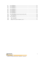


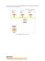


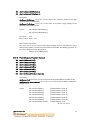
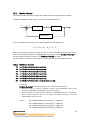


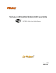

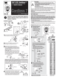
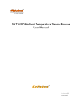
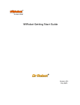
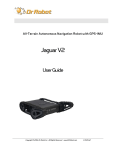
![[P/N: MCB3101] Class I Serial Bluetooth Wireless](http://vs1.manualzilla.com/store/data/005819698_1-328d04723caa8571829b907b8cc9e0c6-150x150.png)