1
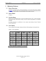
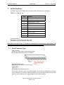
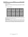
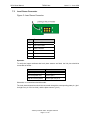
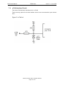
SCH2 User Manual
TSP050.doc
Issue 1.3 – June 2004
This document is the copyright of Money Controls Ltd and may not be reproduced in part or in total by any means,
electronic or otherwise, without the written permission of Money Controls Ltd. Money Controls Ltd does not accept
liability for any errors or omissions contained within this document. Money Controls Ltd shall not incur any penalties
arising out of the adherence to, interpretation of, or reliance on, this standard. Money Controls Ltd will provide full
support for this product when used as described within this document. Use in applications not covered or outside
the scope of this document may not be supported. Money Controls Ltd. reserves the right to amend, improve or
change the product referred to within this document or the document itself at any time.
©Money Controls 2004. All rights reserved.
SCH2 User Manual
TSP050.doc
Issue 1.3 – June 2004
Contents:
1.
2.
3.
Diary of changes............................................................................................................................................ 3
Introduction.................................................................................................................................................... 4
Mechanical Features ..................................................................................................................................... 5
3.1
Hopper Dimensions ................................................................................................................................. 5
3.2
Hopper Weight......................................................................................................................................... 5
3.3
Coin Size Range...................................................................................................................................... 5
3.4
Coin Capacity .......................................................................................................................................... 5
4. Overall Dimensions ....................................................................................................................................... 6
5. Installation and Removal .............................................................................................................................. 7
5.1
Securing the hopper base........................................................................................................................ 7
5.2
Using the 4mm Holes .............................................................................................................................. 7
5.3
Using the keyholes .................................................................................................................................. 7
5.4
Dismantling the hopper............................................................................................................................ 7
5.5
Hopper Assembly .................................................................................................................................... 7
6. Mechanical Description................................................................................................................................. 8
7. ccTalk Interface ............................................................................................................................................. 9
7.1
Serial Connector Type: ............................................................................................................................ 9
7.2
Address Selection:................................................................................................................................. 10
7.3
Level Sense Connector ......................................................................................................................... 11
7.4
ccTalk Interface Circuit: ......................................................................................................................... 12
8. Maintenance................................................................................................................................................. 13
8.1
Clearing a coin jam: ............................................................................................................................... 13
9. Electrical Specification ............................................................................................................................... 14
9.1
External Reset: ...................................................................................................................................... 14
9.2
Coin Payout: .......................................................................................................................................... 14
9.3
Environmental:....................................................................................................................................... 14
10.
Fault Finding and Repair......................................................................................................................... 15
Figures:
Figure 1: Hopper Dimensions .................................................................................................................................. 6
Figure 2: Level Sense Connector .......................................................................................................................... 11
Figure 3: ccTalk cct. .............................................................................................................................................. 12
Tables:
Table 1: Coin Capacities ......................................................................................................................................... 5
Table 2: ccTalk pin out ............................................................................................................................................ 9
Table 3: Address Selection.................................................................................................................................... 10
Table 4: Maintenance Schedule ............................................................................................................................ 13
Table 5: Electrical Specification............................................................................................................................. 14
Table 6: Coin Payout Rate..................................................................................................................................... 14
Table 7: Environmental Ranges ............................................................................................................................ 14
Table 8: Fault Finding and repair........................................................................................................................... 15
©Money Controls 2004. All rights reserved.
Page 2 of 16
SCH2 User Manual
1.
TSP050.doc
Issue 1.3 – June 2004
Diary of changes
Issue 1.0………………………………………………………….………………...26th September 2002
¾
First Issue
Issue 1.1………………………………………………………….……………….…….18th August 2003
¾
Changed ccTalk® to ccTalk throughout the document.
¾
Updated section 7.1 Serial Connector Type:.
¾
Applied TMWP V3.2.
Issue 1.2………………………………………………………….………………...24th September 2003
¾
Added section 7.3 Level Sense Connector.
¾
Ammended coin sizes in section 3.3.
Issue 1.3………………………………………………………….………………...30th June 2004
¾
Changed footer
©Money Controls 2004. All rights reserved.
Page 3 of 16
SCH2 User Manual
2.
TSP050.doc
Issue 1.3 – June 2004
Introduction
The Serial Compact Hopper MK2 (SCH2) is a serially controlled version of the Compact Hopper.
Rather than using the parallel interface of the standard Compact Hopper, the SCH2 uses a serial
interface called “ccTalk”.
The SCH2 has proved security features as well as the ability to “daisy chain” multiple devices to
the same wiring bus. It is also possible with SCH2 to integrate other Money Transaction devices
such as coin, note or card acceptors.
©Money Controls 2004. All rights reserved.
Page 4 of 16
SCH2 User Manual
3.
3.1
TSP050.doc
Issue 1.3 – June 2004
Mechanical Features
Hopper Dimensions
The hopper overall dimensions, mounting arrangement, coin entry and exit points are detailed
in Figure 1. Note that, when used in the side exit mode, the rear of the motor protrudes from
the rear of the casing, within the overall dimensions of the hopper envelope.
3.2
Hopper Weight
570 grams
3.3
Coin Size Range
Hoppers can be configured to pay out coins in the diameter range 16.25 - 31.0mm, and within
the thickness range 1.25-3.20mm. However, each coin needs to be qualified on an individual
coin basis.
For further information on qualification of coins, please contact Money Controls Technical
Services Department.
3.4
Coin Capacity
The coin capacity of the hopper is between 200 and 1000 depending on their physical size.
Table 1: Coin Capacities
Coin
Diameter
(mm)
Thickness
(mm)
SCH2
STD
SCH2
Extended
£2
28.40
2.50
189
252
£1
22.50
3.10
235
314
50p new
27.30
1.80
282
376
20p
21.40
1.80
459
613
10p
24.50
1.83
349
465
5p
18.00
1.73
679
905
2p
25.90
1.80
316
421
1p
20.25
1.43
652
870
Note: these capacities are subject to a +/- 10% error.
©Money Controls 2004. All rights reserved.
Page 5 of 16
SCH2 User Manual
4.
TSP050.doc
Overall Dimensions
Figure 1: Hopper Dimensions
©Money Controls 2004. All rights reserved.
Page 6 of 16
Issue 1.3 – June 2004
SCH2 User Manual
5.
TSP050.doc
Issue 1.3 – June 2004
Installation and Removal
Warning: Ensure that the power has been disconnected from the hopper before removal.
5.1
Securing the hopper base
¾
5.2
Using the 4mm Holes
¾
¾
¾
5.3
Drill 3 holes in the centres shown
Insert 3 holes on the centres shown
Insert 3 x M3.5 screws. DO NOT tighten
Dismantle the hopper
Place base over the back and push far back as possible
Tighten the screws to fit the base in position
Dismantling the hopper
¾
¾
¾
¾
5.5
Drill 4 holes on the centres
Dismantle the hopper
Place base over holes and fix into position using M3 screws
Using the keyholes
¾
¾
¾
¾
¾
¾
5.4
Two sets of fixing holes have been provided in the base to allow the hopper to be
secured in a host machine.
Gently pull out the securing clips on the back of the base.
Tilt the bowl forward until it is clear of the clips.
Slide the bowl forward until the locating lugs are clear of the slots in the base.
Remove the motor assembly from the base and disconnect the cable.
Hopper Assembly
¾
¾
¾
¾
Connect the cable to the motor assembly.
Lower the motor assembly into the base, ensuring the coin exit is in the desired
position.
Locate the lugs at the front of the bowl into the slots at the front of the base.
Gently press down on the top of the bowl until the securing clips (on the base) click
into the slots on the bowl.
©Money Controls 2004. All rights reserved.
Page 7 of 16
SCH2 User Manual
6.
TSP050.doc
Issue 1.3 – June 2004
Mechanical Description
Each disc contains a number of holes in which the coins are held. The disc is driven via a gear
train, by the motor. As the disc rotates, the coin at the bottom of one of the stacks will make
contact with the ejector fingers. The fingers will move back and, at the same time, the coin will
start to move outwards to the exit slot.
Once the coin reaches the exit slot, the spring loaded ejector fingers will be able to return to
their original position and, in doing so, will push the coin out of the hopper.
An optical coin detector is created by infrared transmitters and photo detectors situated on the
PCB. The infrared light beam is routed across the exit slot via a light guide. When a coin passes
through the exit the light beam will be broken and a coin output signal will be generated.
There are a range of discs, ejector fingers and adjuster plates available to provide optimum
performance for coins within the specified range.
©Money Controls 2004. All rights reserved.
Page 8 of 16
SCH2 User Manual
7.
TSP050.doc
Issue 1.3 – June 2004
ccTalk Interface
The SCH2 uses ccTalk interface with a 10 pin connector with the pinouts as follows:-
Table 2: ccTalk pin out
Pin
Function
1
Address Select 3 – MSB
2
Address Select 2
3
Address Select 1 – LSB
4
+Vs
5
+Vs
6
0V
7
0V
8
/DATA (ccTalk)
9
N/C
10
/RESET
ccTalk parameters:
Remember to configure the baud rate to 9600.
The hopper can only operate at 9600 baud.
Note: Refer to issue 4.2 of the ‘ccTalk Serial Communication Protocol/Generic Specification’ for
an explanation of the protocol and it’s implementation on any platform.
7.1
Serial Connector Type:
PCB Connector
2.54mm (0.1-inch) pitch 10 way with locking wall.
Part number: Molex 22-27-2101 or equivalent
Serial Connector Pinout:Operation can be achieved with just 3 wires.
+24 V to pin 4.
GND to pin 6.
Bi-directional serial data line to pin 8.
Pins 4 and 5, and pins 6 and 7 are linked internally. The provision of extra pins is to simplify
the manufacture of a multi-drop cable using thicker wire for the power leads. There can be a
‘power in’ and a ‘power out’ pin, and the hoppers can be ‘daisy chained’.
©Money Controls 2004. All rights reserved.
Page 9 of 16
SCH2 User Manual
7.2
TSP050.doc
Issue 1.3 – June 2004
Address Selection:
The default ccTalk bus address for a ‘payout’ device is 3. This is the address of the Serial
Compact Hopper if no connections are made to the address select pins (pins 1 to 3) on the
connector.
Table 3: Address Selection
Address
Select 3
Address
Select 2
Address
Select 1
Serial
Address
3
X
X
X
4
5
X
X
6
7
X
X
X
X
X
X
8
9
X
10
For applications requiring more than one hopper on the serial bus, one or more of the
address select lines may be connected to +Vs. A total of 8 unique bus address may be
generated in this way, in the range 3 to 10 inclusive.
X = Connect to +Vs
A number of mating connections on a multi drop bus cable may be wired uniquely to allow
operation of multiple hoppers. Since address selection is done externally, any Serial
Compact Hopper may be plugged into any position on the bus and the host machine will
know which one is paying out a particular coin. Address determination from the connector is
only done at power up or reset. Changing the address select lines afterwards has no effect.
©Money Controls 2004. All rights reserved.
Page 10 of 16
SCH2 User Manual
7.3
TSP050.doc
Issue 1.3 – June 2004
Level Sense Connector
Figure 2: Level Sense Connector
Pin
Function
1
High Level Plate
3
Low Level Plate
5
Plate Common
2
High Level Link
4
Low Level Link
6
Link Common
Operation
To notify the hopper software that level plate sensors are fitted, the link pins should be
connected as follows…
Mode
Connections
High level plates only
pin 2 to pin 4
Low level plates only
pin 4 to pin 6
High & low level plates
pin 2 to pin 4 to pin 6
Otherwise, no connections should be made.
The level plates themselves should be connected through the corresponding plate pin ( pin 1
for high level, pin 3 for low level ) and the plate common ( pin 5 ).
©Money Controls 2004. All rights reserved.
Page 11 of 16
SCH2 User Manual
7.4
TSP050.doc
Issue 1.3 – June 2004
ccTalk Interface Circuit:
This is the ccTalk electronic interface circuit on SCH2.
There are many options for the host interface circuit but we recommend an open collector
drive.
Figure 3: ccTalk cct.
©Money Controls 2004. All rights reserved.
Page 12 of 16
SCH2 User Manual
8.
TSP050.doc
Issue 1.3 – June 2004
Maintenance
Warning: Coin dust may accumulate in the hopper during use. Inhalation of the dust should be
avoided during maintenance operation. Ensure that the power has been disconnected before
any maintenance operations are performed.
Table 4: Maintenance Schedule
Maintenance Schedule
8.1
Every 50,000 to 100,000
depending on coin type.
Using a mild detergent on a damp cloth.
No spray solvents should be used.
Every 500,000 coins
Replace ejector fingers and spring
Every 1,000,000 coins
Replace adjuster plate
Expected product lifetime
3 Million coins (with routine maintenance)
Clearing a coin jam:
¾
¾
¾
Remove all coins from bowl.
Remove motor assembly from base as described.
Clear the jammed coin by either:
i.
ii.
¾
¾
¾
¾
Rotating the disk manually, first anti-clockwise then clockwise to free the coin
OR
Push the coin back in using another coin.
Remove any debris from the disk bed assembly.
Clean the exit window opto with a clean dry cloth.
Re-assemble, as described.
Refill and test the hopper.
©Money Controls 2004. All rights reserved.
Page 13 of 16
SCH2 User Manual
9.
TSP050.doc
Issue 1.3 – June 2004
Electrical Specification
MCL recommend a 24V, 4A power supply.
24 volt motor version
Table 5: Electrical Specification
9.1
Electrical Specification
Value
Supply Voltage
+24V
Typical Operating Current/No Load
0.35A
Typical Operating Current/Max Load
0.9A
Surge Current/Start Up and Reverse
3.6A
Typical Payout Rate
8 to 10 coins per second
External Reset:
Signal, active low with 10K pull up to +5V
9.2
Input volts (low)
0.6V max
Input volts (High)
3.5V min (5.0V max)
Coin Payout:
Table 6: Coin Payout Rate
9.3
Mode
Rate
Multi coin payout
8 - 10 coins per second approx
Single coin payout
2 coins per second approx
Environmental:
Table 7: Environmental Ranges
Operating Temperature
0 to 600 C
Storage Temperature
-20 to 700 C
Operating Humidity
10 to 75% RH
Storage Humidity
10 to 95% RH non condensing
Note: For cctalk protocol information, please contact Money Controls Technical Services
Department on +44 161 955 0124.
©Money Controls 2004. All rights reserved.
Page 14 of 16
SCH2 User Manual
TSP050.doc
Issue 1.3 – June 2004
10. Fault Finding and Repair
Table 8: Fault Finding and repair.
Problem:
Coins fail to unjam:
Motor fails to run:
Over payout of coins:
Under Payout Of Coins:
Check:
Cure:
Ensure coin exit is clear.
Remove blockage from coin
exit.
Ensure correct coins in hopper.
Fill hopper with correct coins.
Ensure no badly bent coins in
hopper.
Remove bent coin/s.
Supply fuse.
Replace fuse.
Protection device tripped.
Wait 30 seconds with supply
OFF.
Hopper has detected an opto
fault.
Check EEPROM flags.
Check opto area/coin exit area
for dirt.
Clean opto/coin exit area.
Check opto area/coin exit area
for dirt.
Clean opto/coin exit area.
Ensure
hopper
sufficient coins.
contains
Refill hopper.
©Money Controls 2004. All rights reserved.
Page 15 of 16
SCH2 User Manual
TSP050.doc
Issue 1.3 – June 2004
This manual is intended only to assist the reader in the use of this product and
therefore Money Controls shall not be liable for any loss or damage whatsoever
arising form the use of any information or particulars in, or any incorrect use of the
product. Money Controls reserve the right to change product specifications on any
item without prior notice.
©Money Controls 2004. All rights reserved.
Page 16 of 16


![TSP030 ccEuroTeach User Manual V1[1].4(2)](http://vs1.manualzilla.com/store/data/005682308_1-f9d13610d7f8864488377d3c706bdc7d-150x150.png)